Open HardwareAssembly Instructions
Guides for installation and assembly of the LulzBot line of products made by FAME 3D LLC.
Guides for installation and assembly of the LulzBot line of products made by FAME 3D LLC.
Gather parts
1x- Left frame (PP-FP0055_rD)
1x- Lower strain relief (PP-GP0265_v1.2)
2x- M3x8 BHCS (HD-BT0137)
2x- M3 black oxide washer (HD-WA0038)
Tools needed: 2mm hex driver
Instructions:
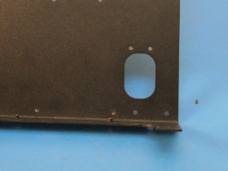
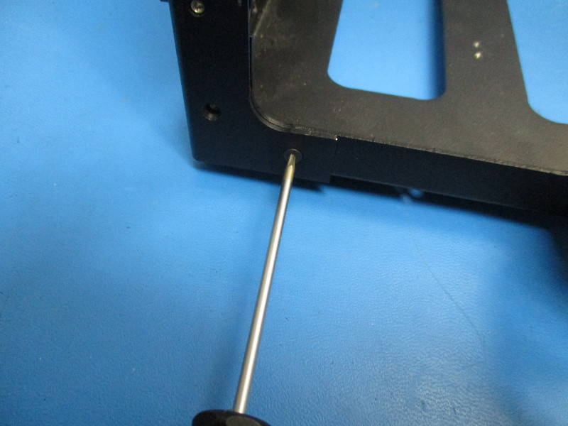
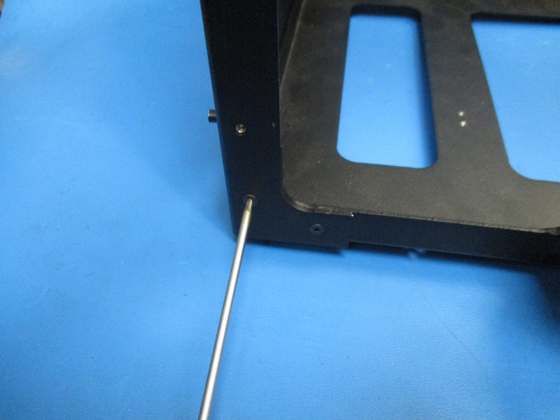
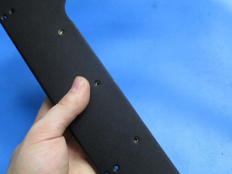
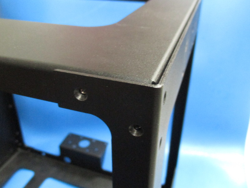
Align the lower strain relief with the holes on the left frame (see image “Securing part” for mounting location and part orientation)
Secure the lower strain relief with two M3x8 BHCS with washers, torquing it to 5in*lbs.
Gather parts
3x- M3x8 BHCS (HD-BT0137)
3x- M3 black oxide washers (HD-WA0038)
1x- upper strain relief (AS-PR0066)
Tools needed: 2mm hex driver
Instructions:
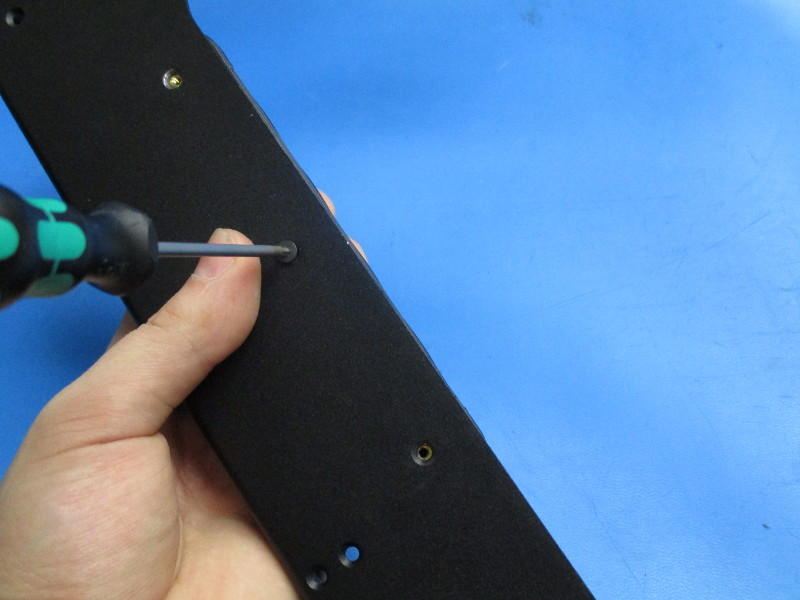
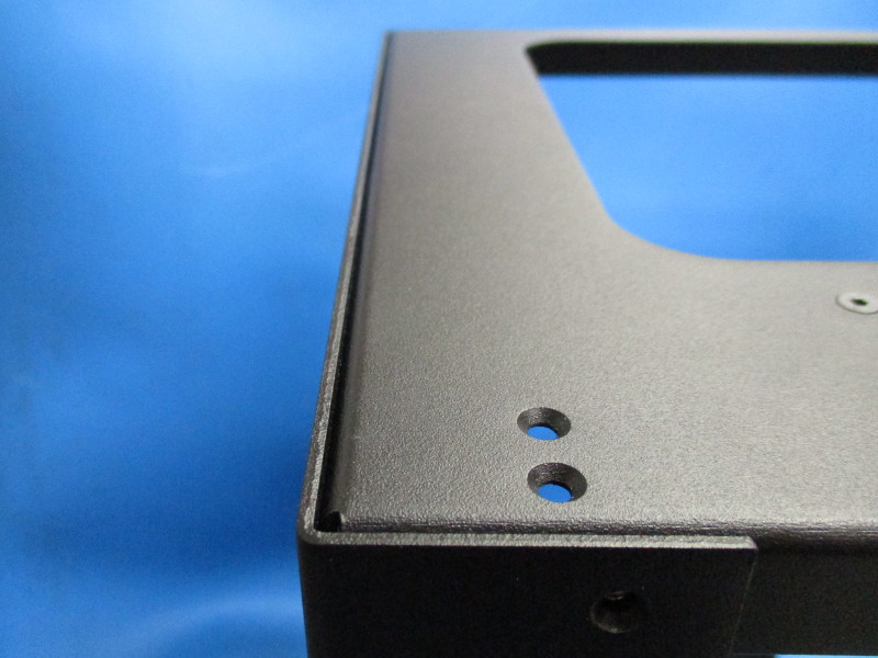
Align the upper strain relief holes with the three holes in the left frame.
Secure the upper strain relief using three M3x8 BHCS with washer. Torque to 5in*lbs.

Gather parts
1x- Female chain mount
2x- M3x6 FHCS (HD-BT0128)
Tools needed: 2mm hex driver
Instructions:
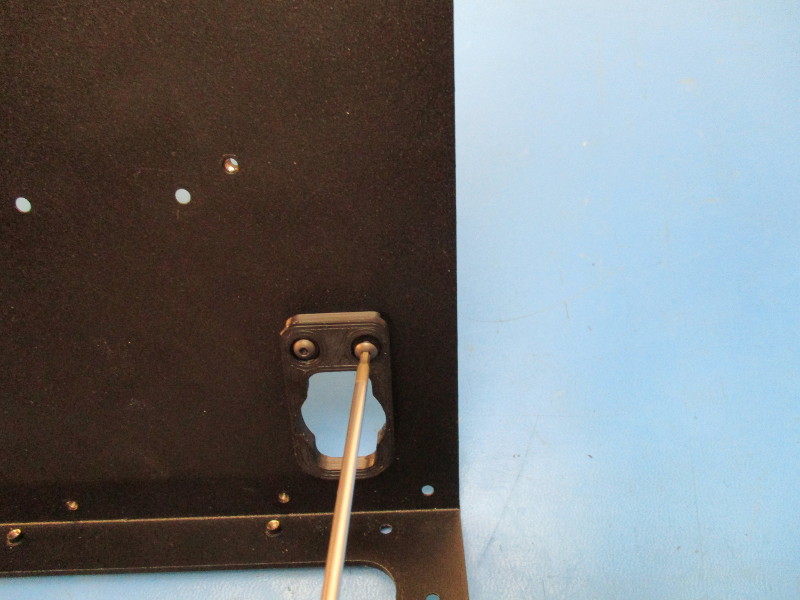
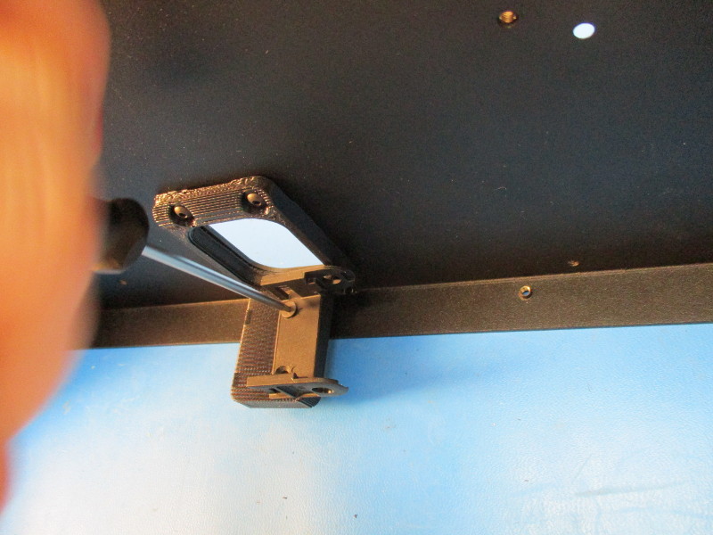
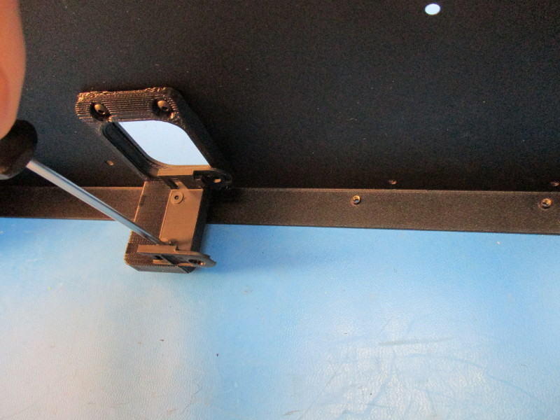
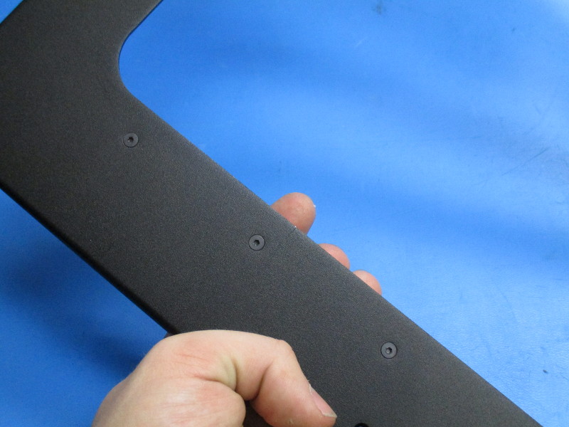
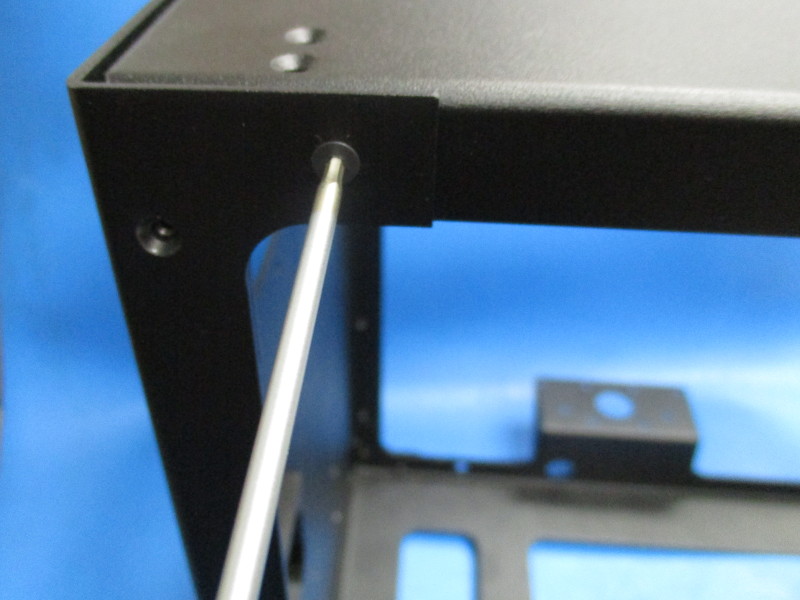
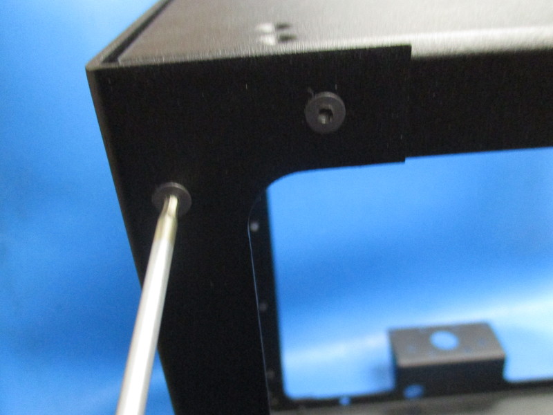
Orient the chain mount on the upper strain relief. (see image “Fastening chain 1”) Align the counter sunk holes in the chain mount with the threaded inserts in the upper strain relief.
Fasten the chain mount to the upper strain relief using the M3x6 FHCS. Torque to 5in*lbs
Gather parts
7x- M3x6 FHCS (HD-BT0128)
Right frame (PP-FP0052_rC)
1x- M3x8 BHCS Stainless steel (HD-BT0104)
External tooth serrated lock washer (HD-WA0035)
Bottom frame (PP-MP0149)
Tools needed: 2mm hex driver
Instructions:
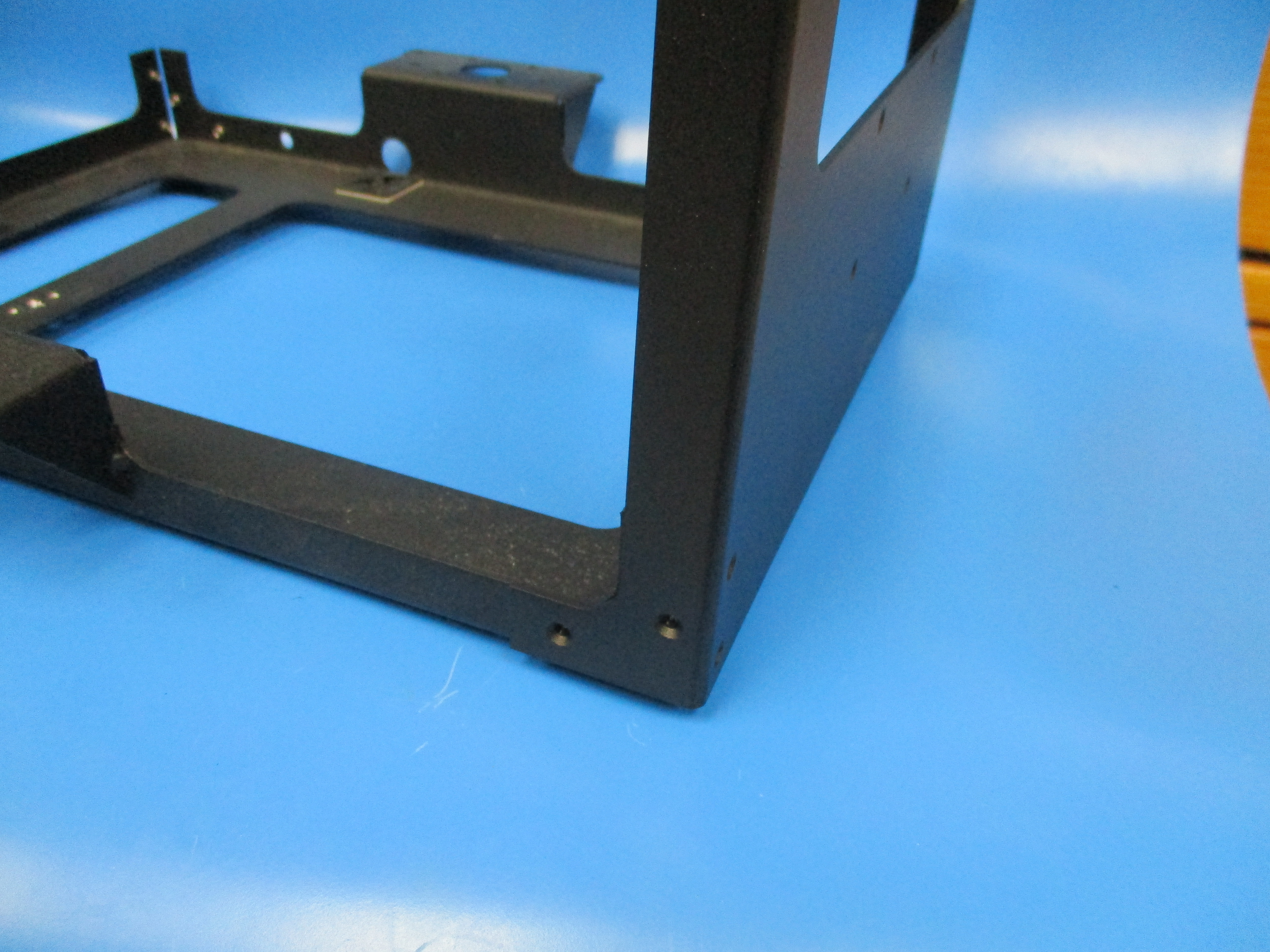
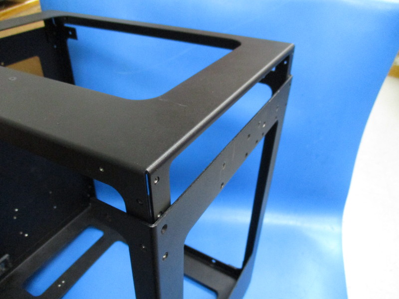
Slide the left frame over the bottom frame.
Align the holes of the two frames
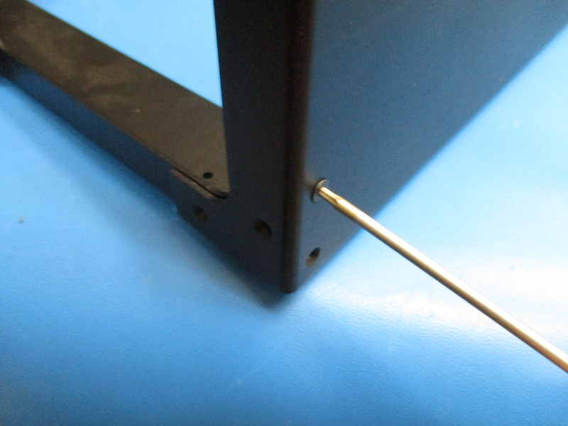
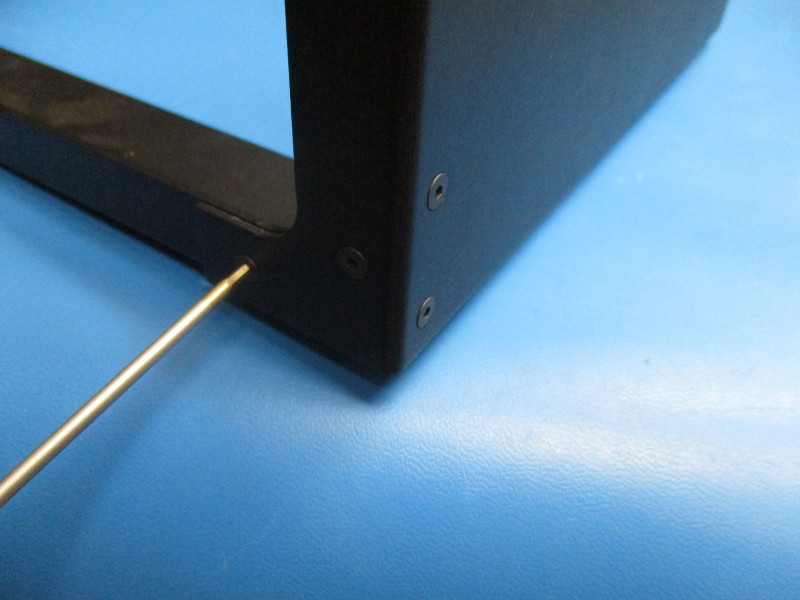
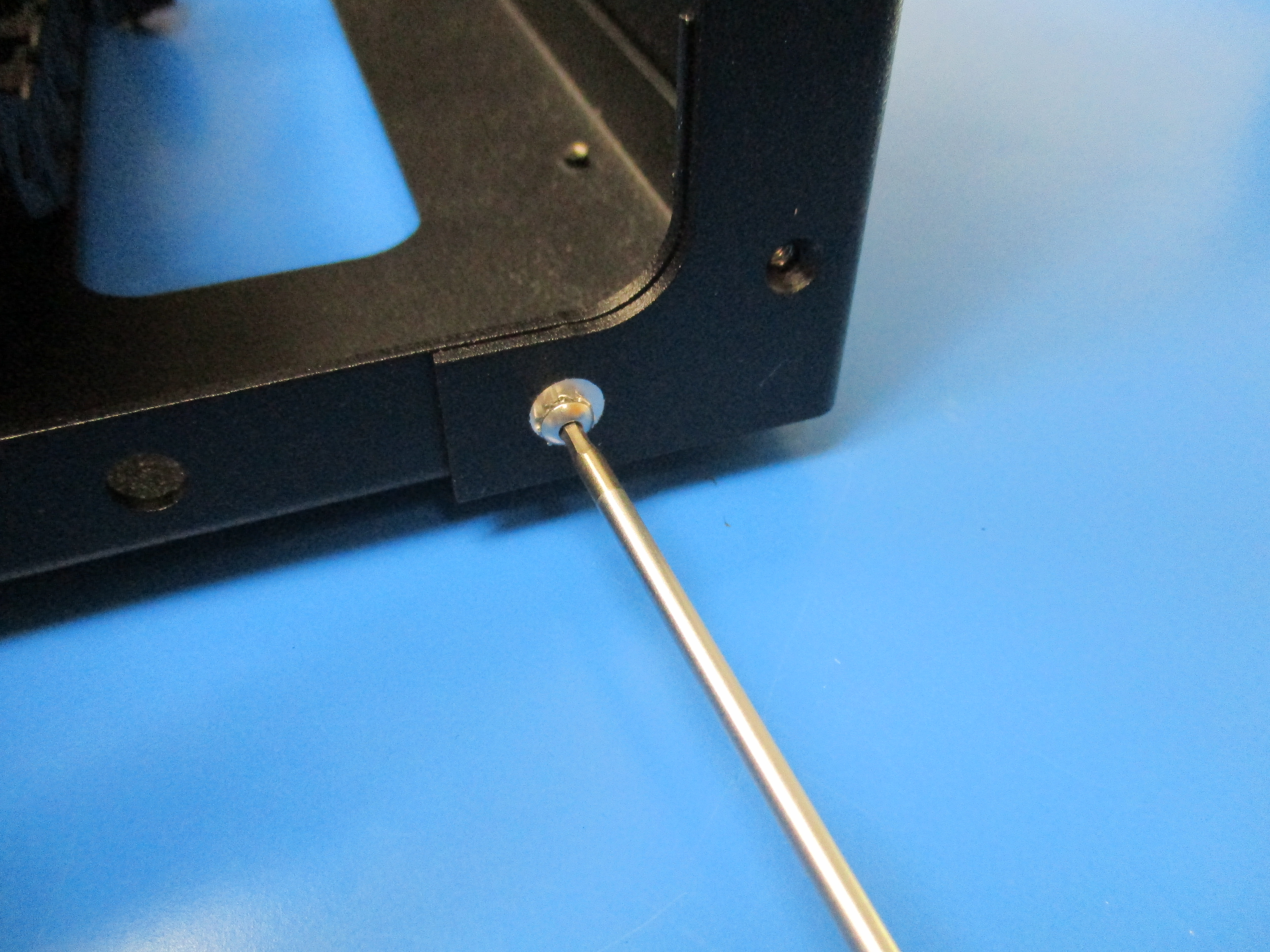
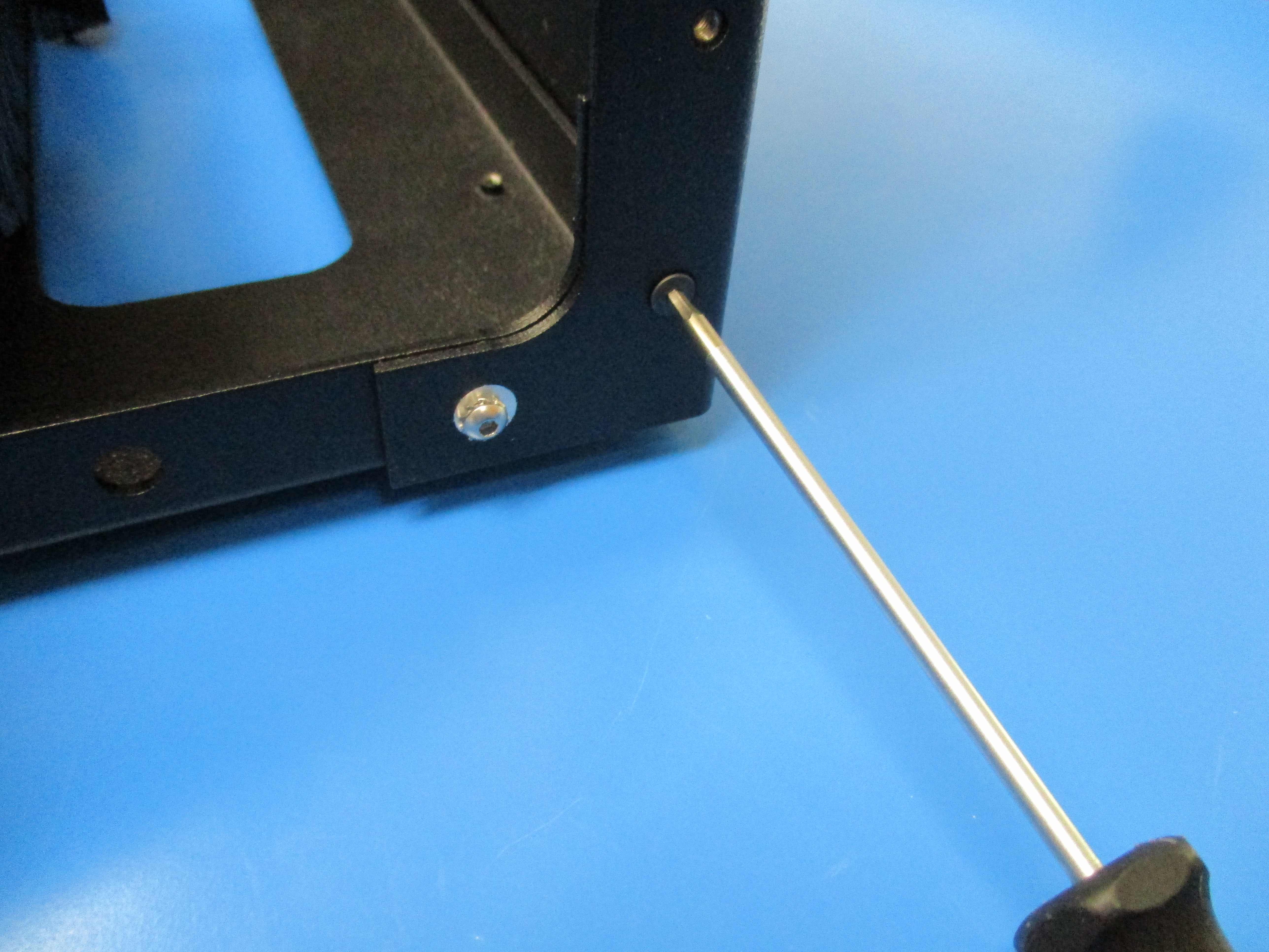
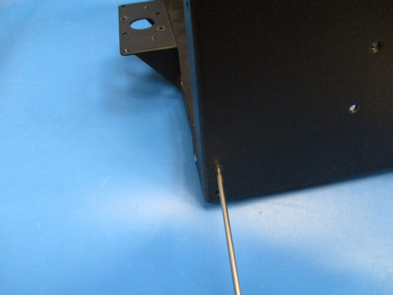
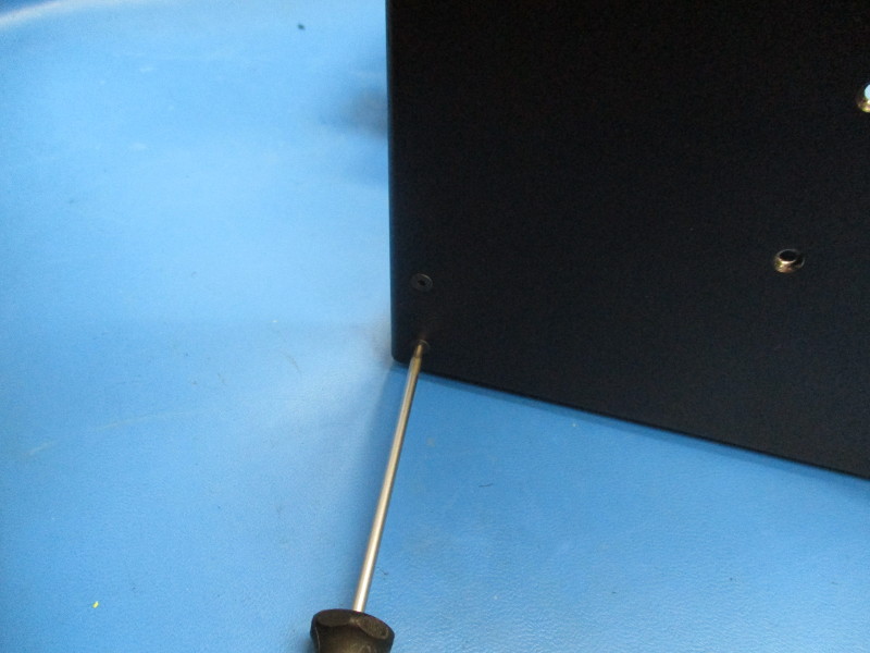
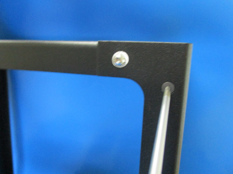
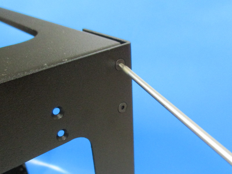
On the back of the printer (Motor side), fasten one M3x8 BHCS stainless steel screw, with washer, into the non countersunk hole on the back of the printer that lines up with the threaded hole in the bottom plate. Torque to 5in*lbs
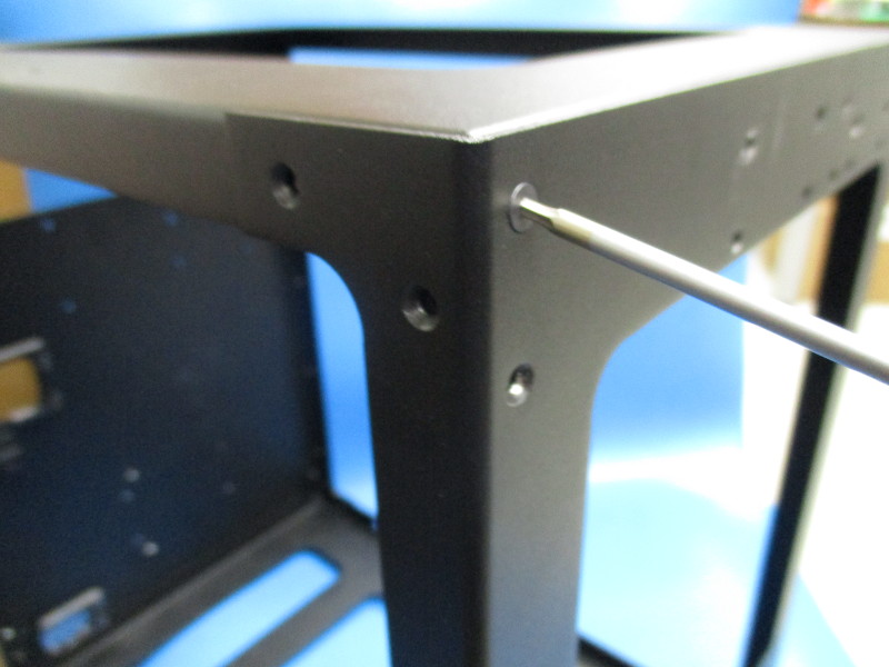
Fasten one M3x6 FHCS into the counter sunk hole on the back of the printer that lines up with the hole in the bottom frame. Torque to 5in*lbs
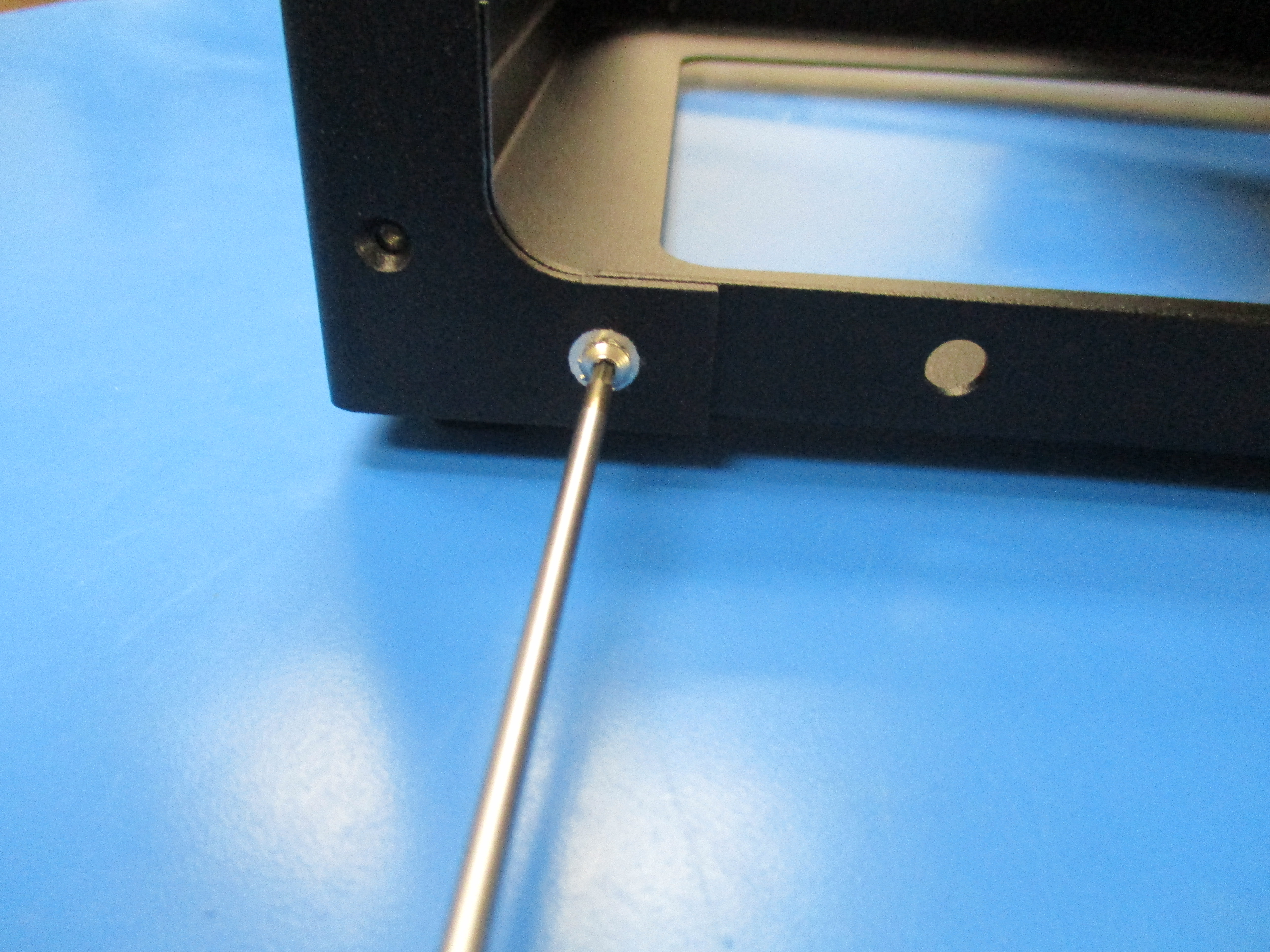
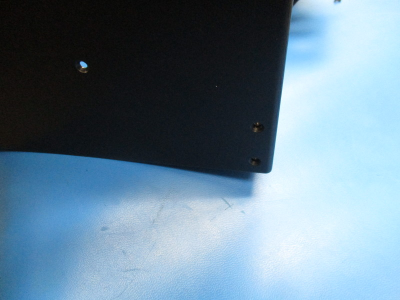
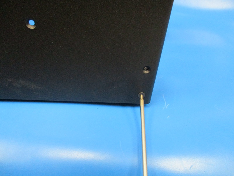
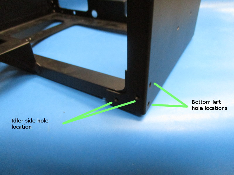
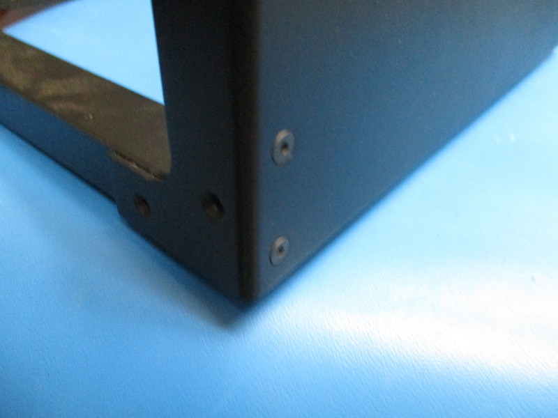
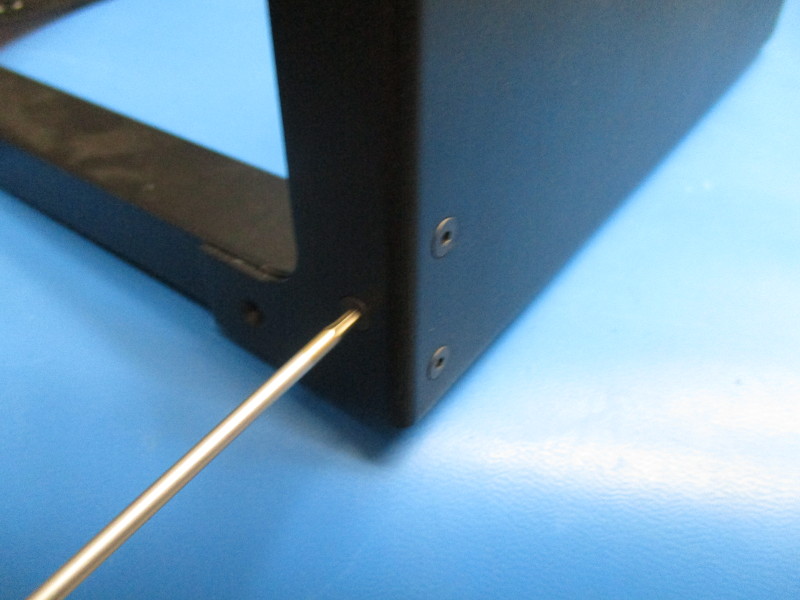
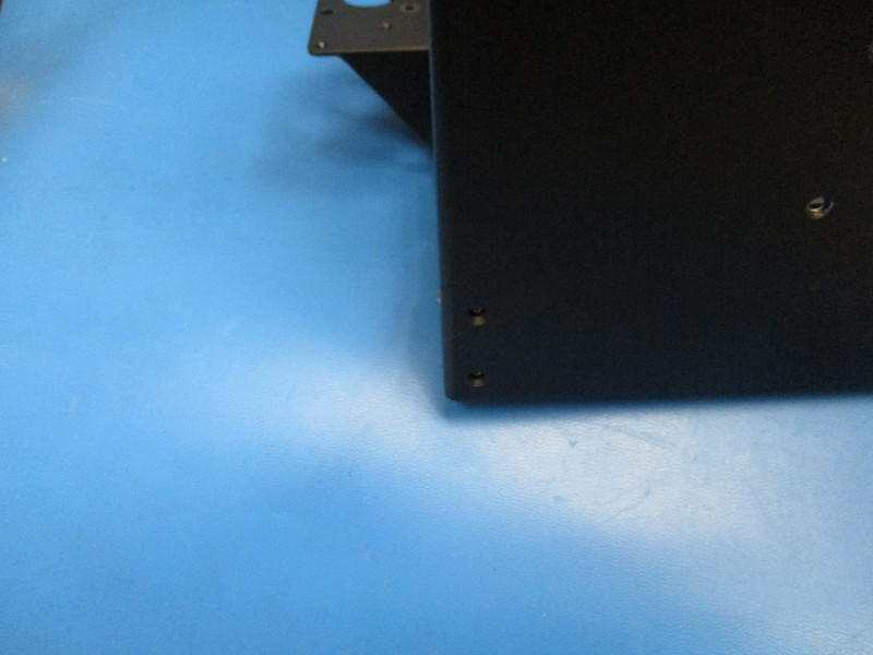
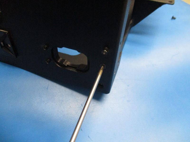
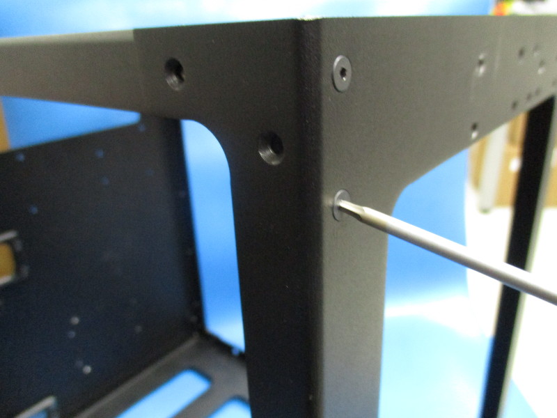
Rotate the bottom frame so the face of the right frame is facing front. Fasten two M3x6 FHCS into the bottom left corner counter sunk holes of the right frame. Fasten two M3x6 FHCS into the bottom right corner counter sunk holes of the right frame. Torque to 5in*lbs
Rotate the frames so that the idler side is facing front. Fasten two M3x6 FHCS into the bottom left countersunk holes. Torque to 5in*lbs


Gather parts
7x- M3x6 FHCS (HD-BT0128)
Left frame (PP-FP0055_rD)
1x- M3x8 BHCS Stainless steel (HD-BT0104)
External Tooth serrated lock washer (HD-WA0035)
Tools needed: 2mm hex driver
Instructions:
Slide the left frame over the bottom frame.
Align the holes of the two frames
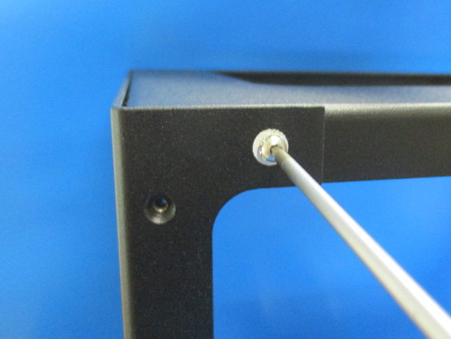
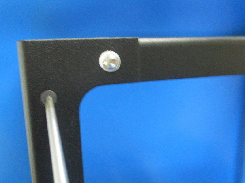
Fasten one M3x8 BHCS stainless steel screw, with star washer, into the non countersunk hole on the back of the printer that lines up with the threaded hole in the bottom plate.
On the back of the printer (motor side), fasten one M3x6 FHCS into the counter sunk hole on the back of the printer that lines up with the hole in the bottom frame. Torque to 5in*lbs
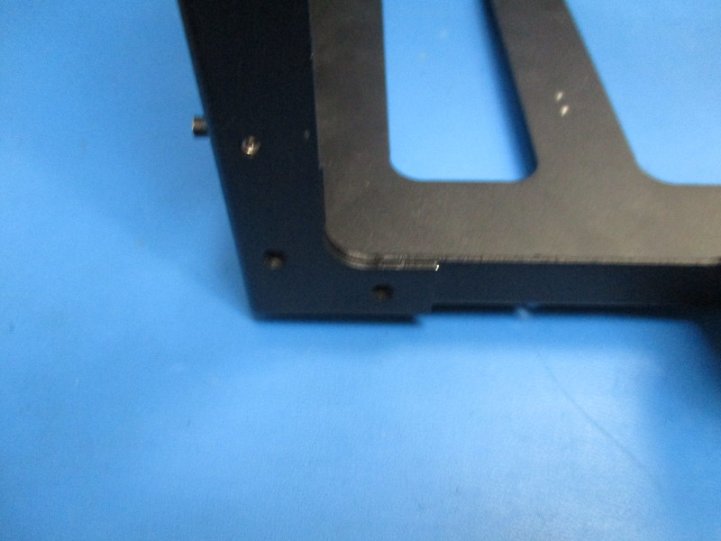
Rotate the bottom frame so the face of the left frame is facing front. Fasten two M3x6 FHCS into the bottom right corner counter sunk holes of the left frame. Fasten two M3x6 FHCS into the bottom left corner counter sunk holes of the left frame. Torque to 5in*lbs
Rotate the frames so that the idler side is facing front. Fasten two M3x6 FHCS into the bottom left countersunk holes. Torque to 5in*lbs


Gather parts
1x- handle, black (AS-PR0065)
3x- M3x6 FHCS (HD-BT0128)
1x- Top frame (PP-FP0051_rC)
Tools needed: 2mm hex driver
Instructions:
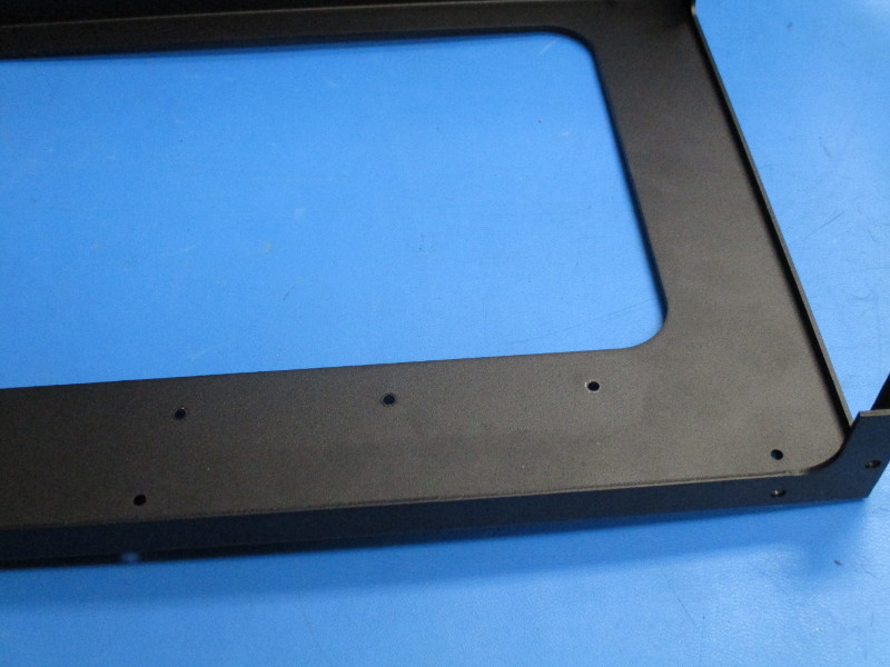
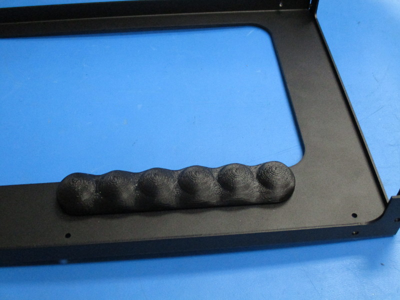
Lay the top frame on the back side.
Line the handlebar with the three holes in the frame towards the front.
Secure the handle by fastening three M3x6 FHCS through the counter sunk holes in the frame into the threaded inserts in the handle. Torque to 5in*lbs

Gather parts
14x- M3x6 FHCS (HD-BT0128)
2x- M3x8 BHCS SST (HD-BT0104)
2x- External Tooth serrated lock washer (HD-WA0035)
Tools needed: 2mm hex driver
Instructions:
Slide the top frame in between the left and right frame. Ensure the handle on the top frame is oriented to the front ( idler side) of the printer.
Align the holes. Torque all screws on the frame to 5in*lbs
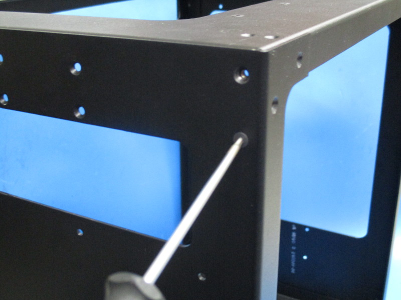
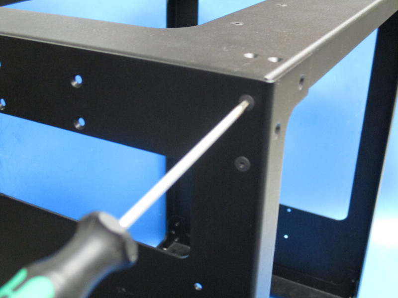
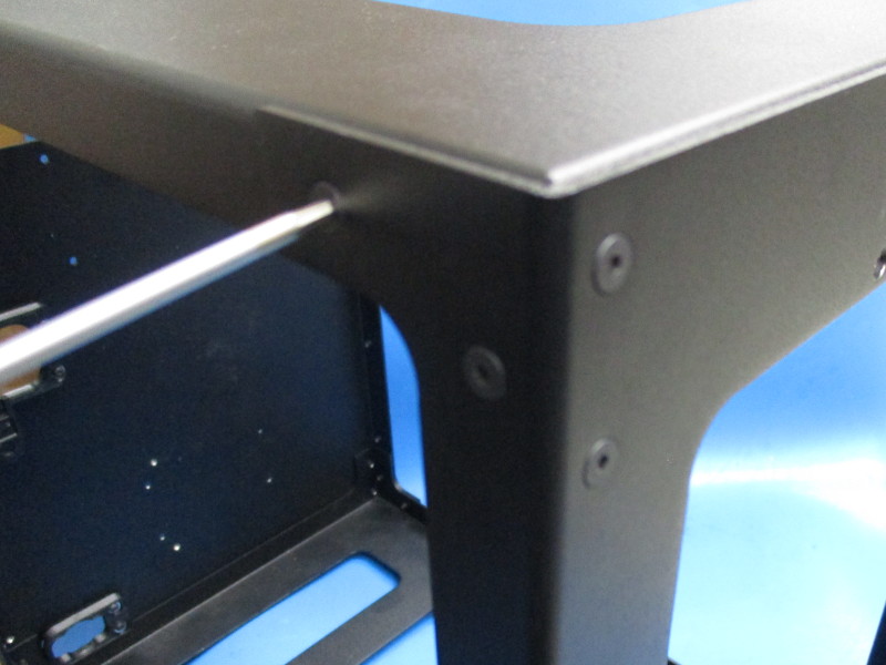
On the front (idler side), fasten two M3x6 FHCS screws into the top left corner
Rotate the frames so the motor side is on the left and the idler side is on the right. Fasten two M3x6 FHCS screws into the top right corner. Fasten two M3x6 FHCS screws into the top left corner.
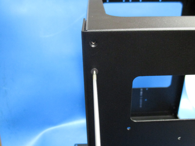
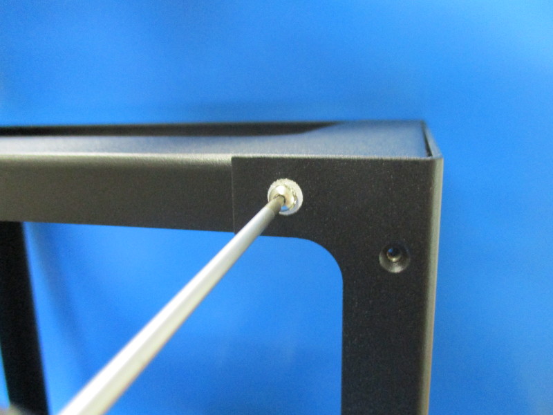
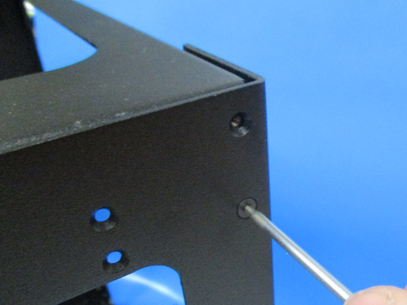
Rotate the frames so the motor side is in facing front. Fasten one M3x8 BHCS stainless steel screw, with star washer, into the non countersunk hole in the top right corner. Fasten one M3x6 FHCS screw into the top right corner. Fasten one M3x6 FHCS screws into the top left corner. Fasten one M3x8 BHCS stainless steel screw, with star washer, into the non countersunk hole in the top left corner.
Rotate the frames so the motor side is on the right and the idler side is on the left. Fasten two M3x6 FHCS screws into the top right corner. Fasten two M3x6 FHCS screws into the top left corner.
Rotate the frames so the idler is in facing front. Fasten two M3x6 FHCS screws into the top right corner.

Gather parts
Instructions:
Flip the printer onto the left frame
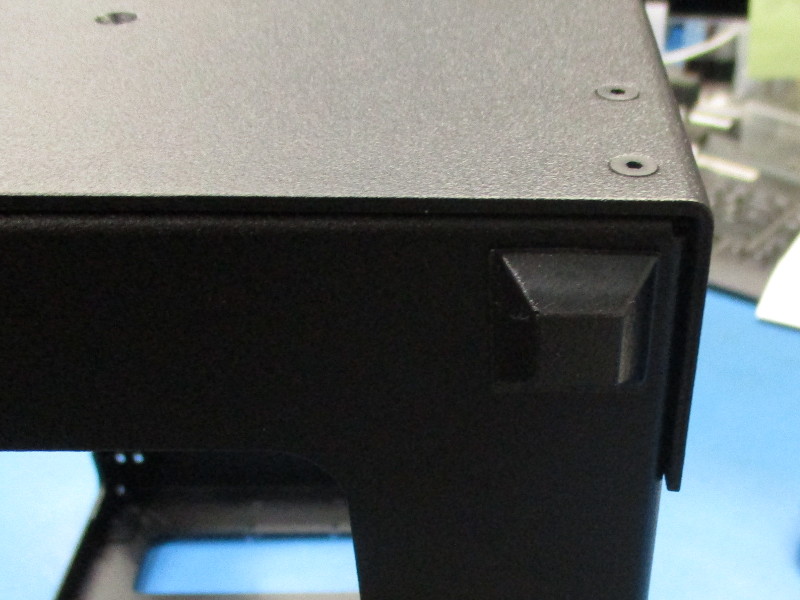
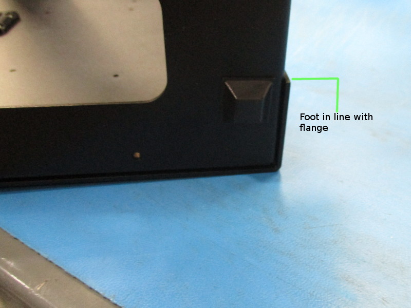
Place two rubber bumper squares in the front corner and back corner on the right frame side.
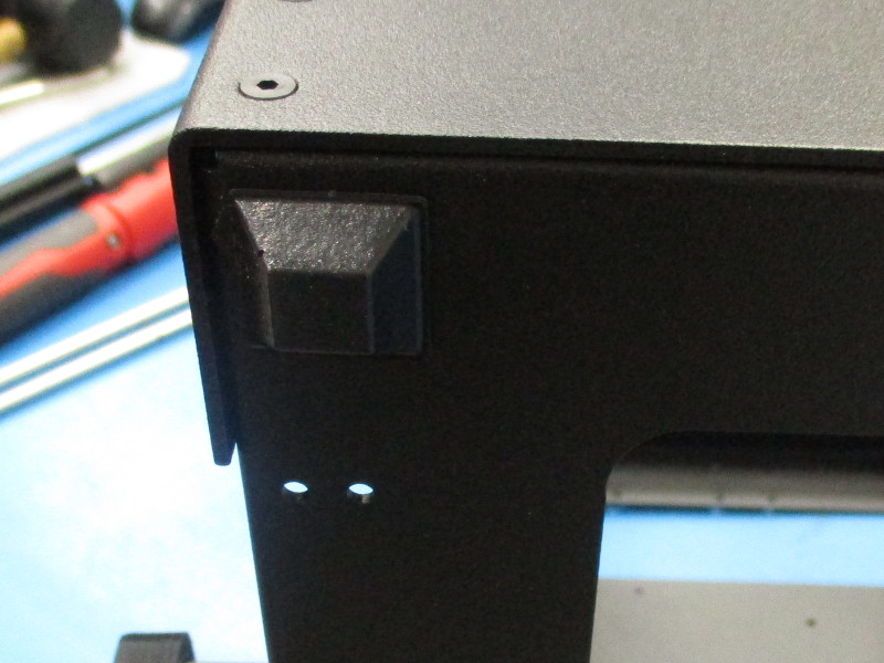
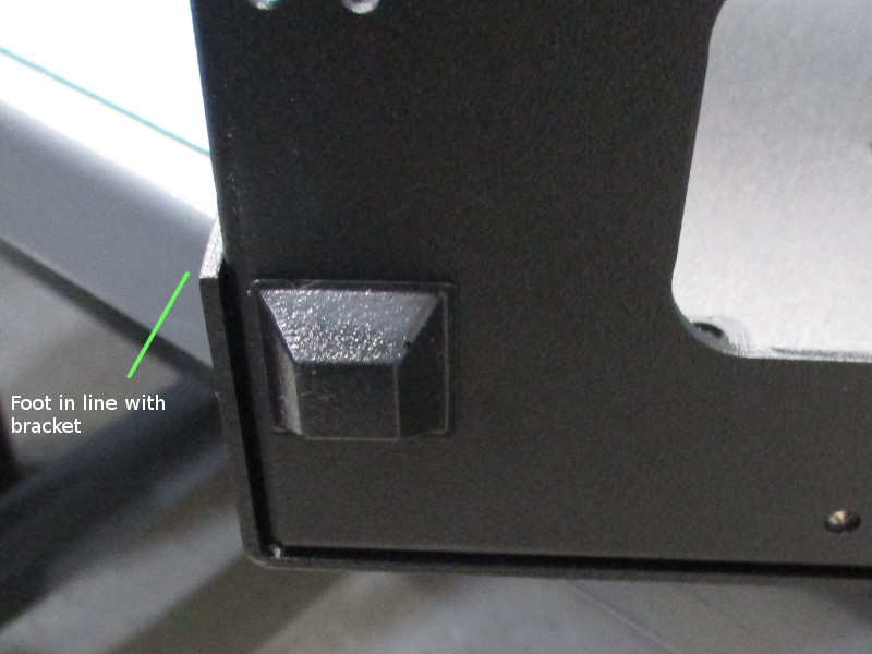
Place two rubber bumper squares in the front corner and back corner of the left frame side. The squares need to be aligned with the left frame brackets. (see image “ left square alignment”)