Open HardwareAssembly Instructions
Guides for installation and assembly of the LulzBot line of products made by FAME 3D LLC.
Guides for installation and assembly of the LulzBot line of products made by FAME 3D LLC.
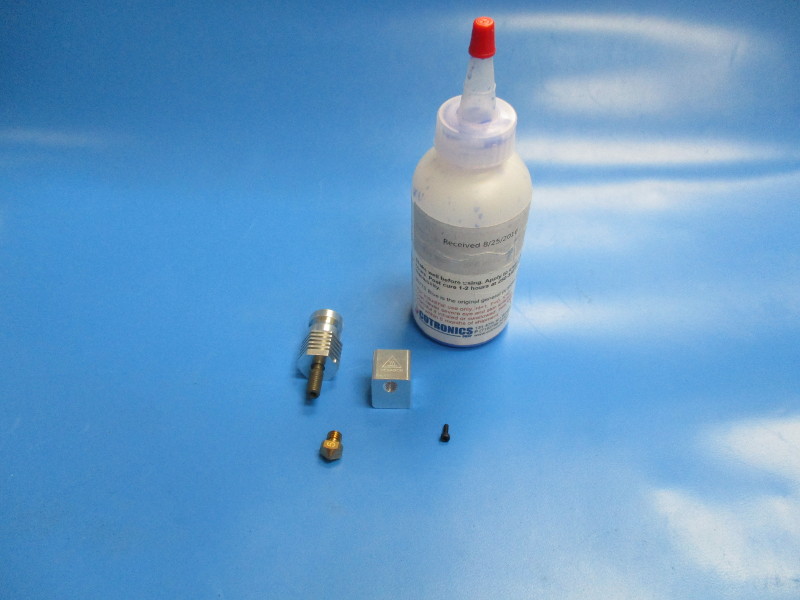
Gather parts
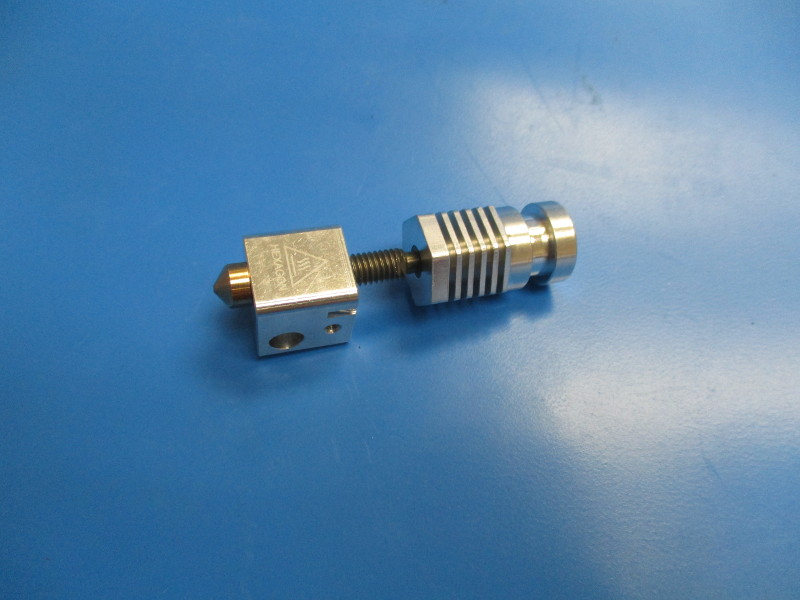
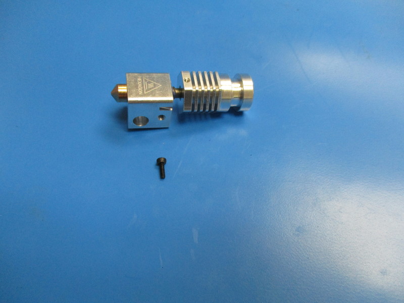
Hexagon hot end with Heat break (PP-MP0133)
Hexagon heater block (PP-MP0134)
0.5mm nozzle for 3mm filament (PP-MP0135)
High temperature thread locker (TL-CS0040)
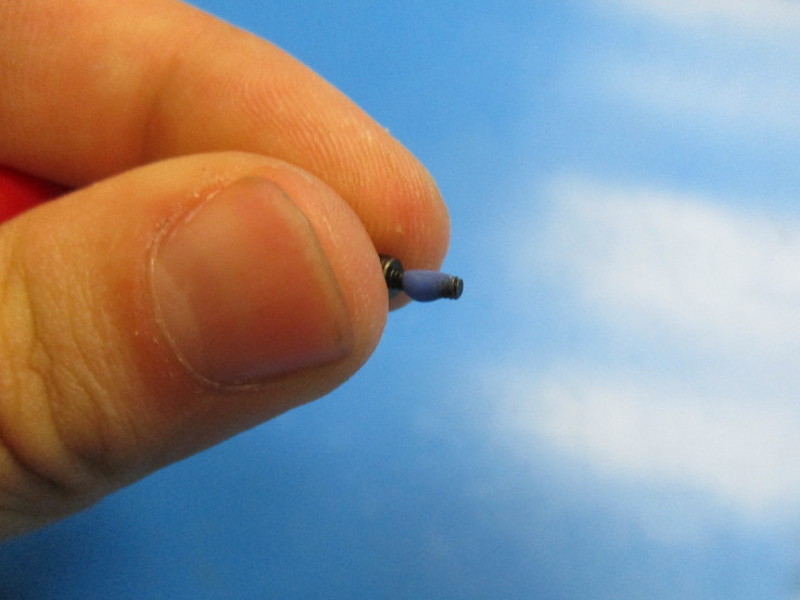
Heat sink set screw (HD-BT0173)
Tools needed: 1.5mm hex driver
                   Torque wrench with 7mm attachment

                   18mm attachment

                   18mm wrench

                   4.5mm wrench

                   Compressed air
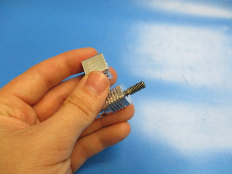
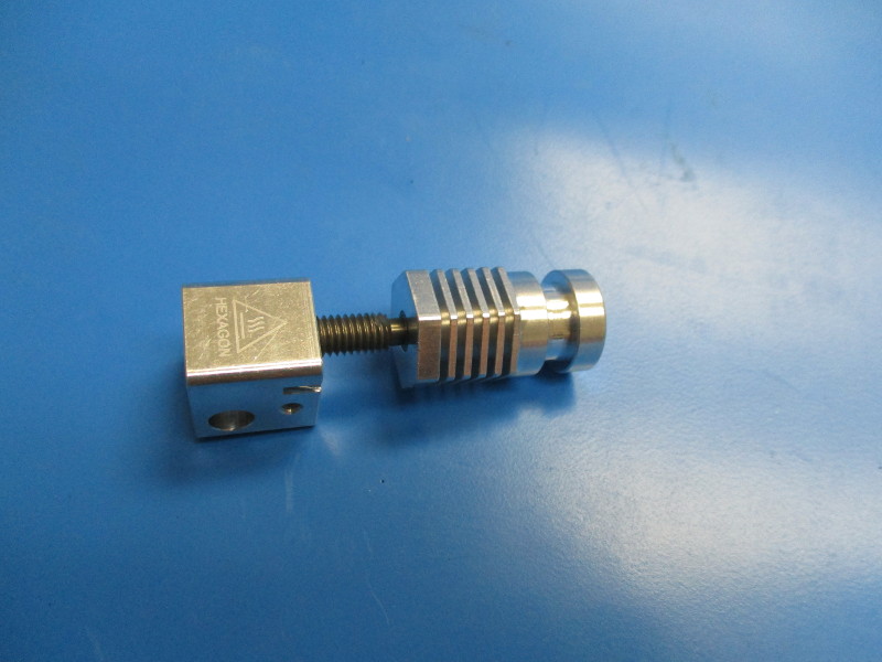
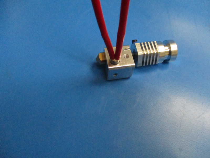
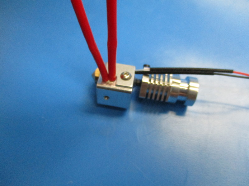
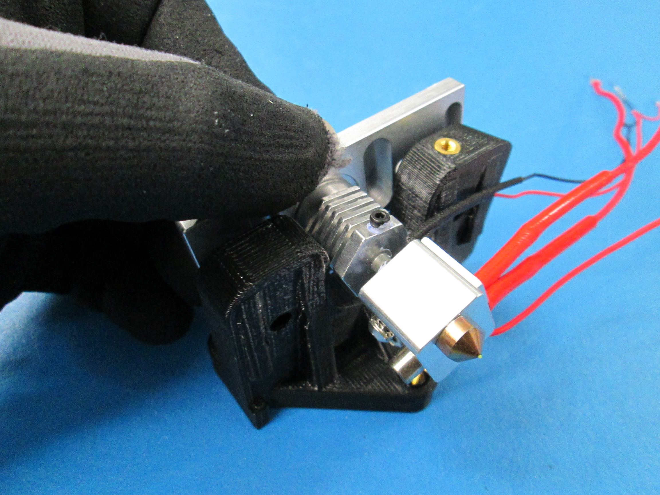
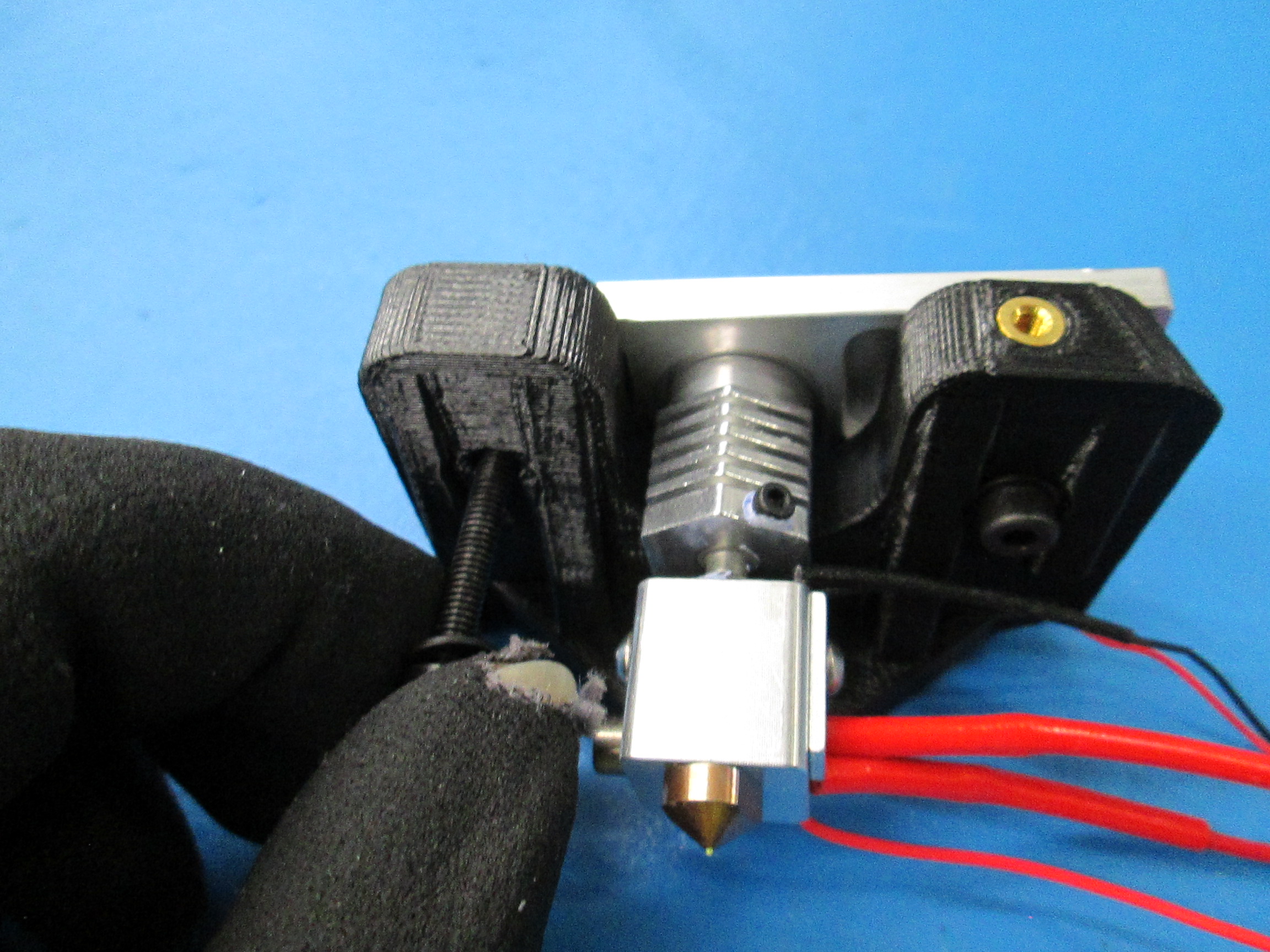
Take the heat sink and thread it into the top hole on the heater block (see image “threading heat sink” for heater block orientation)
Thread the heat sink all the way onto the heater block until the heat sink bottoms out on the heater block.
Unscrew the heat sink from the heater block so that metal burrs can be blown out.
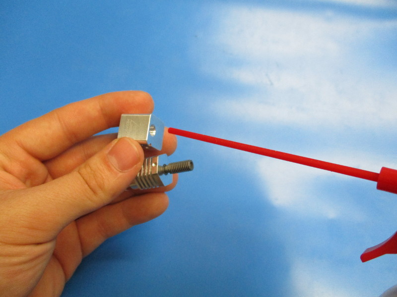
Blow air through the threaded hole for the heat sink in the heater block. Blow air onto the heat break (threaded portion). Ensure metal burrs are non-existent on the heat break and in the heater block.
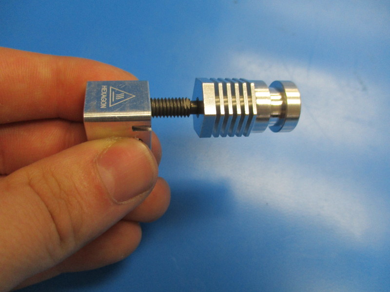
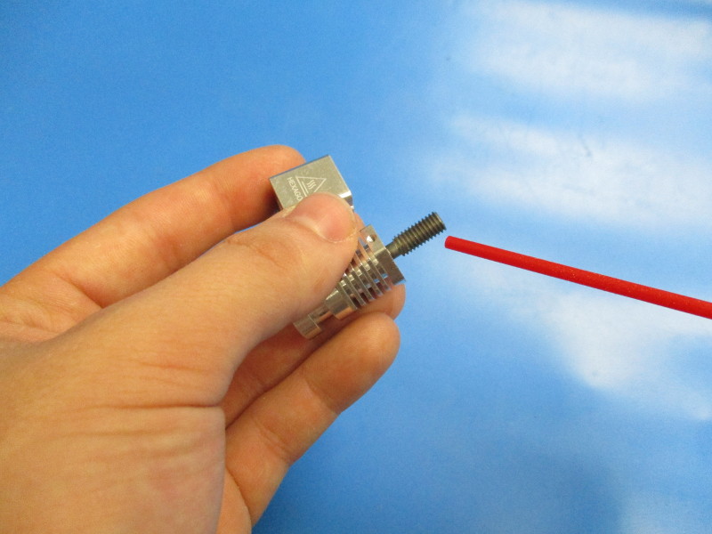
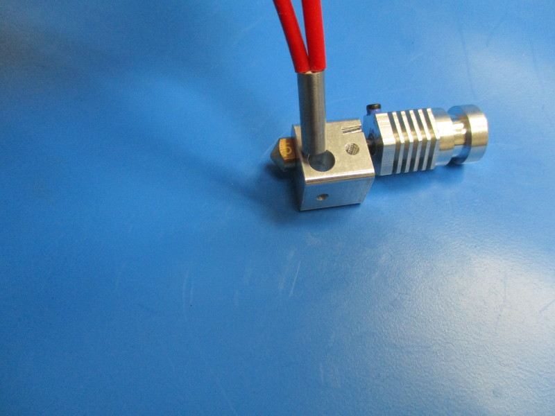
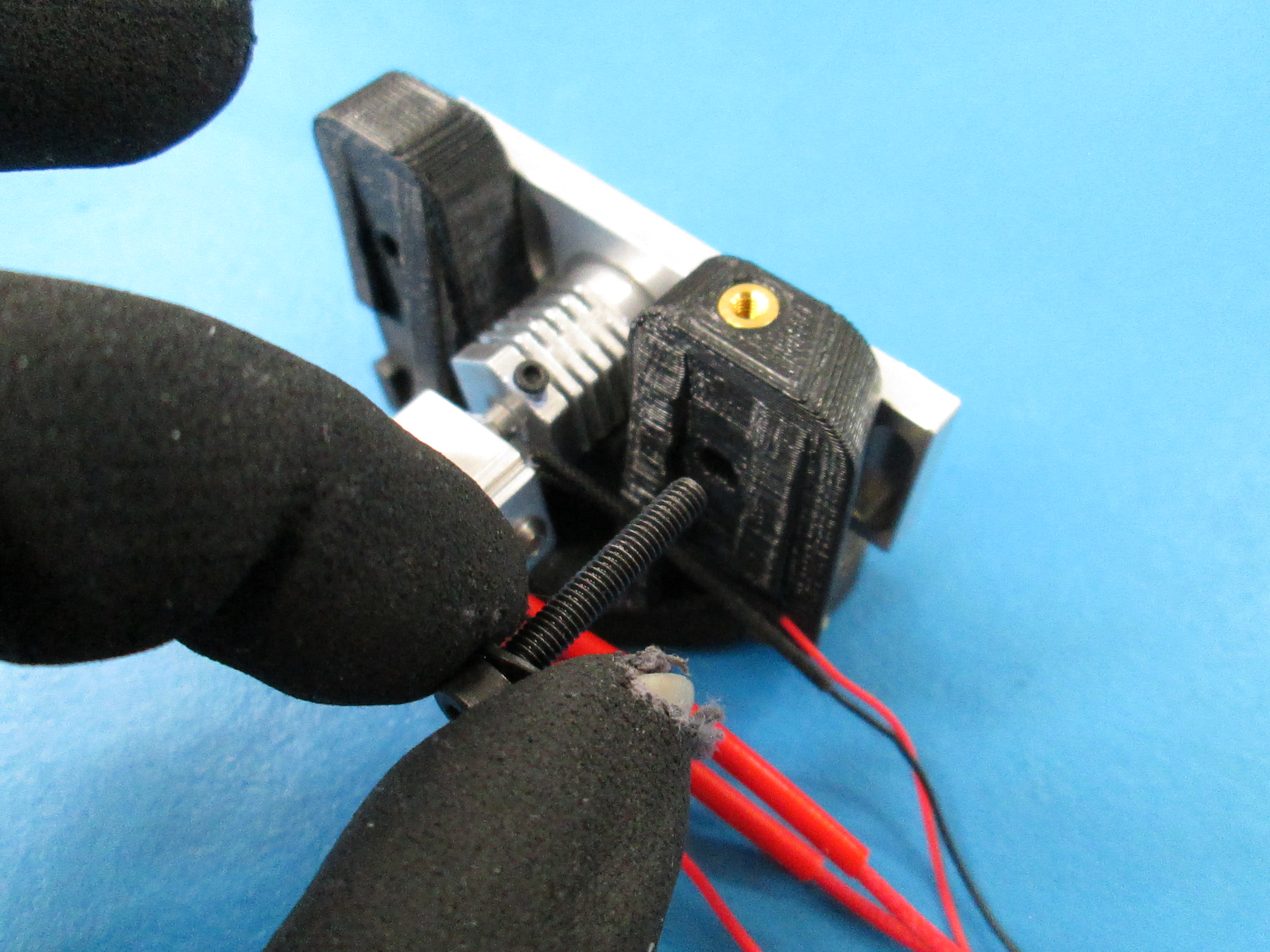
Thread the first two threads of the heat break into the heater block

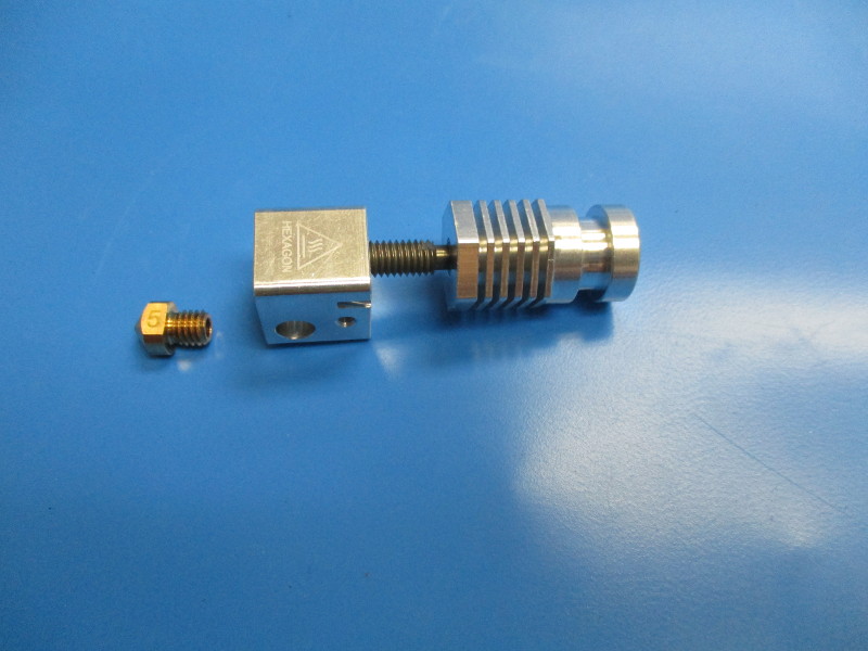
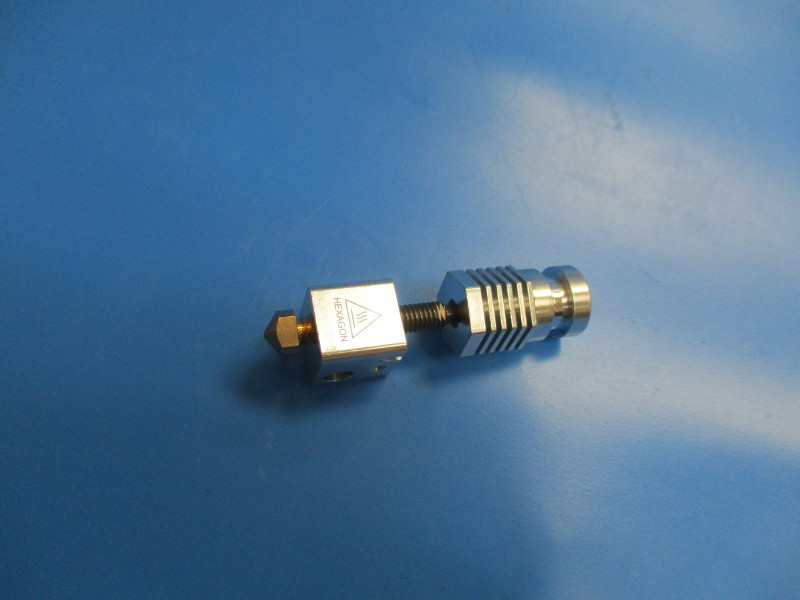
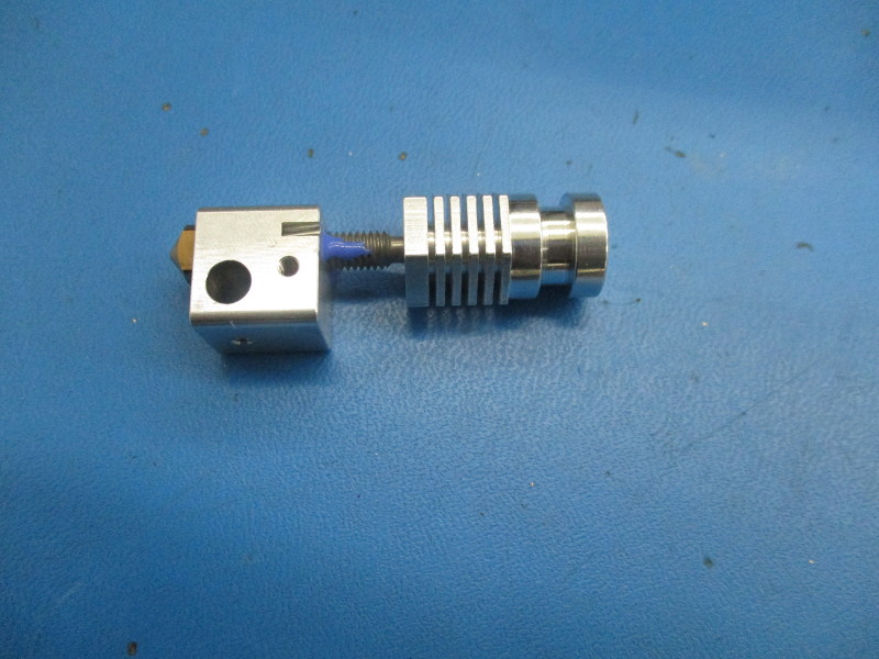
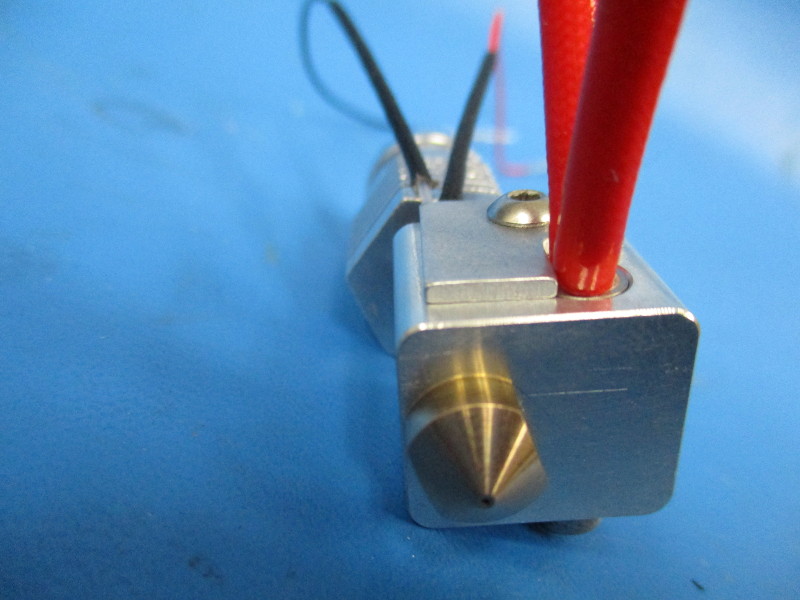
Take the 0.5 nozzle and thread it into the heater block (see image “ nozzle threaded “ for orientation of heater block)
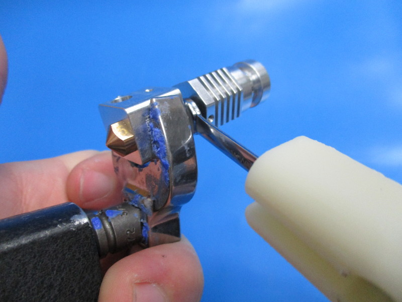
Threat the nozzle in until it is finger tight against the heater block. Torque the nozzle by using the 18mm wrench on the heater block and the 7mm attachment on the torque wrench. Torque to 30in*lbs.
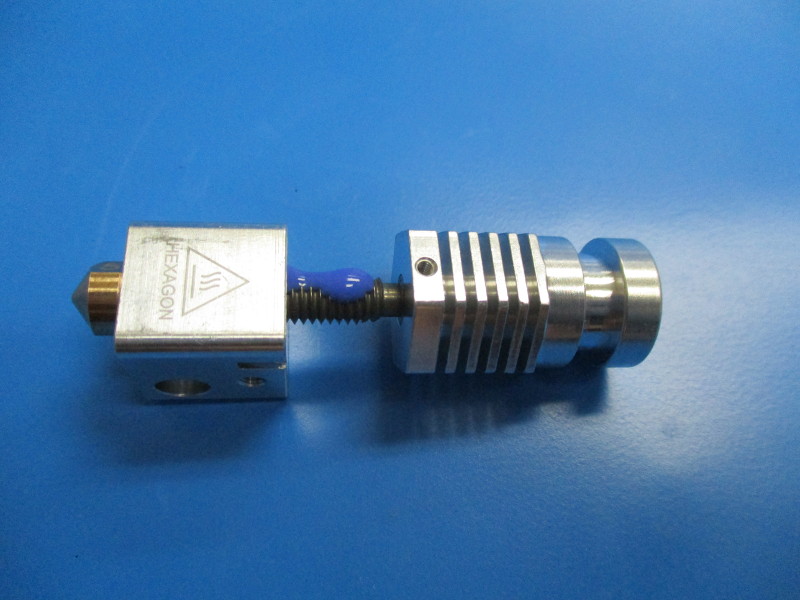
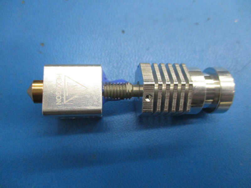
Apply a liberal amount of thread locker from the exposed threads from the heater block up to the top thread on the heat break.
Apply thread locker on the opposite side of the heat break. Cover 4 threads on this side.
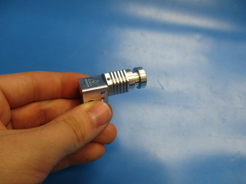
Finger tighten the heat sink down until it bottoms out.
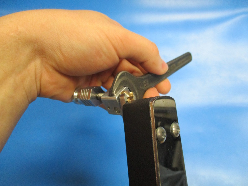
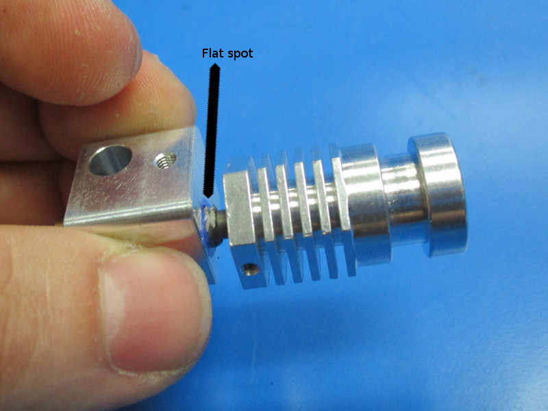
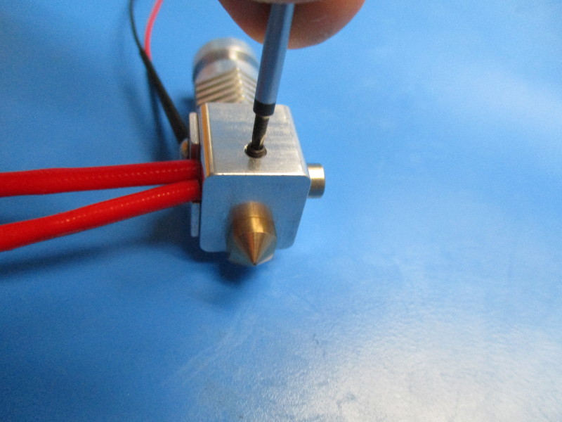
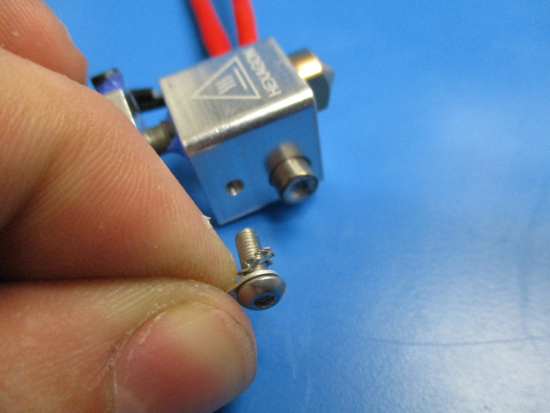
On the heat break, the top two threads have flat spots parallel to each other. (see image “heat break flat spots”) Use the 4.5mm wrench on the heat break and the 18mm attachment, for the torque wrench, on the heater block to torque the heater block to 15in*lbs.
Tools needed: 1.5mm hex driver
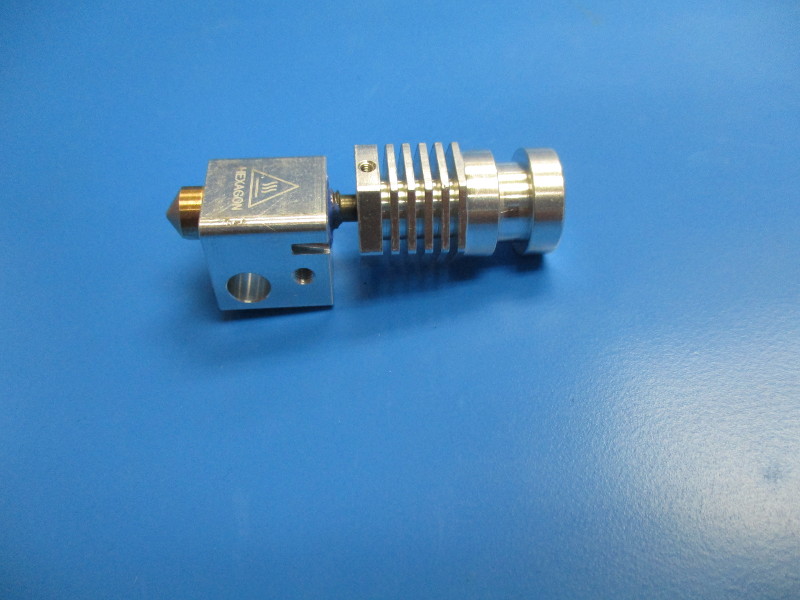
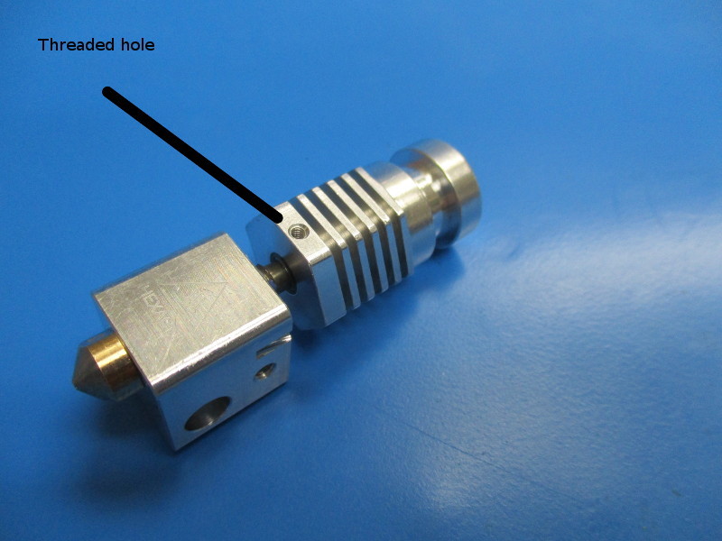
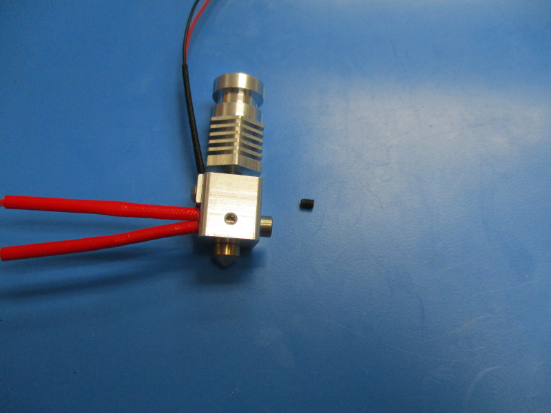
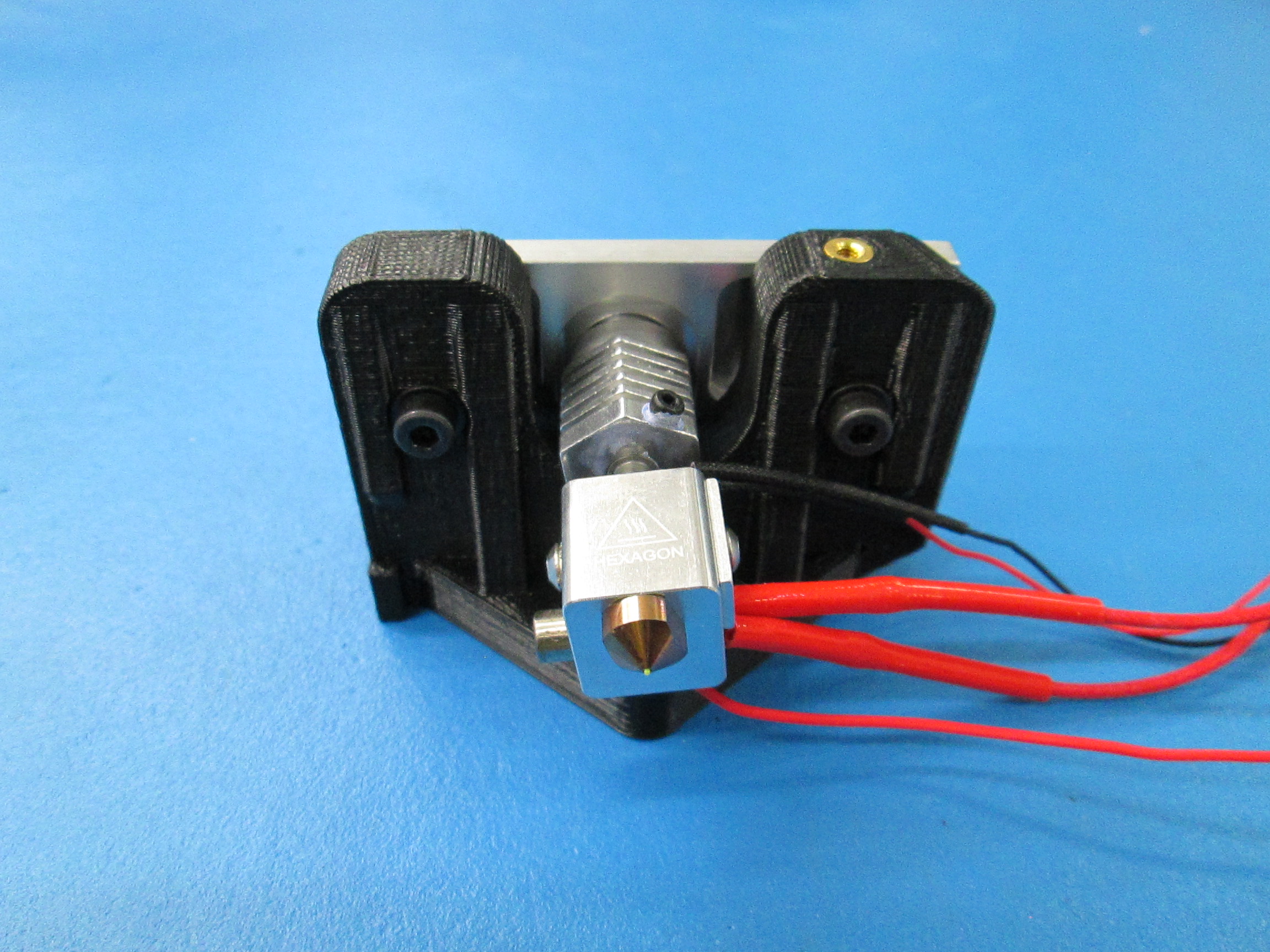
Locate the threaded hole on one of the faces of the heat sink. This hole will need to be on the backside if possible. Rotate the heat sink around until the hole is on the back side. If the heat sink feels like its too tight to rotate, leave it be.
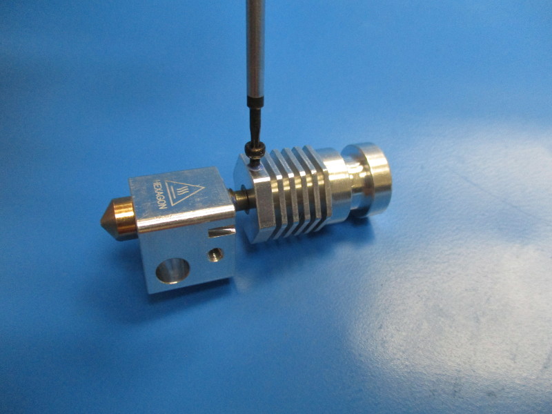
Coat the heat sink set screw with thread locker. Thread the screw into the heat sink hole and torque to 5in/lbs
Wiring harnesses needed for the Mini V 1.04 extruder:
1x- AS-HE0005 - Hexagon Hot End, .5mm Assembly, Mini Single
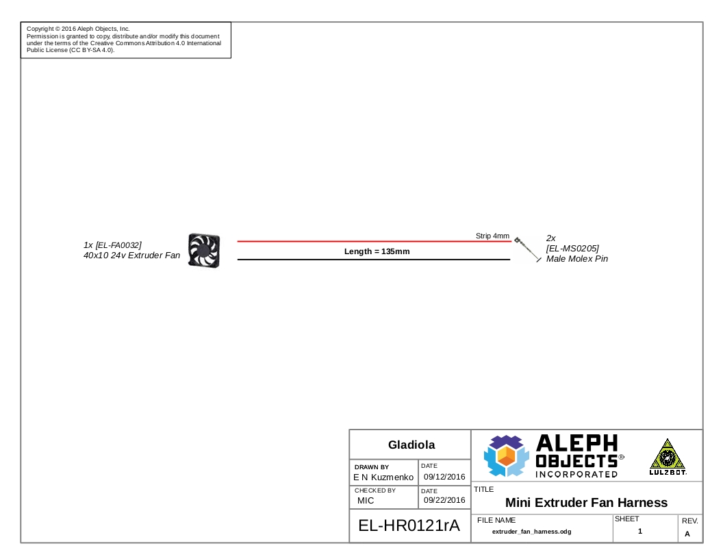
1x- EL-HR0121 - Mini, Nozzle Fan Harness
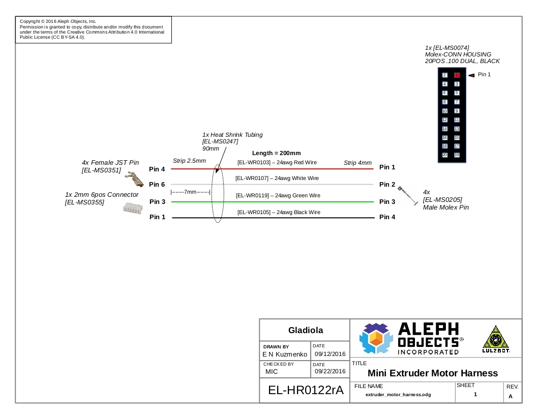
1x- EL-HR0122 - Mini, Extruder Motor Harness
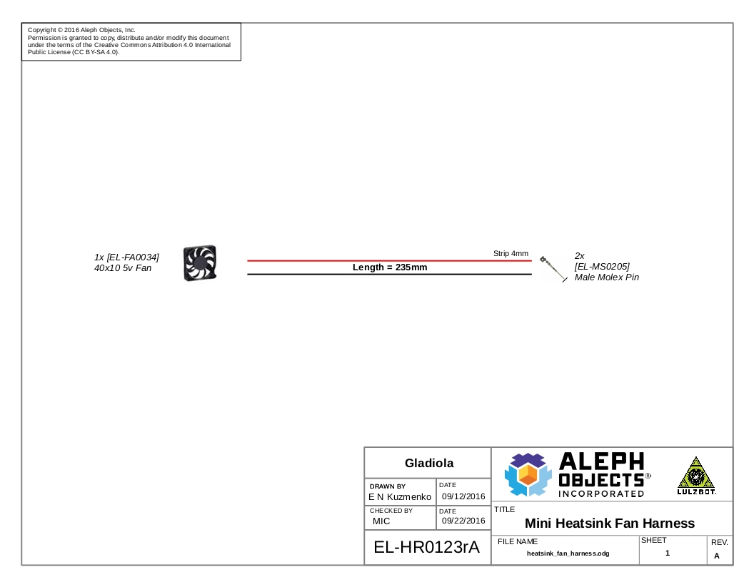
1x- EL-HR0123 - Mini, Heatsink Fan Harness
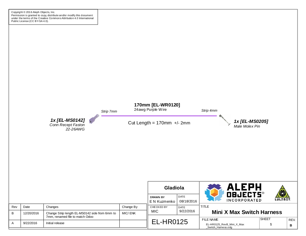
1x- EL-HR0125 - Mini X Max Switch Harness

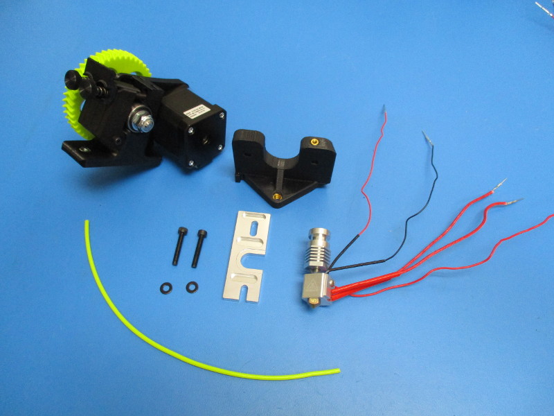
Gather parts
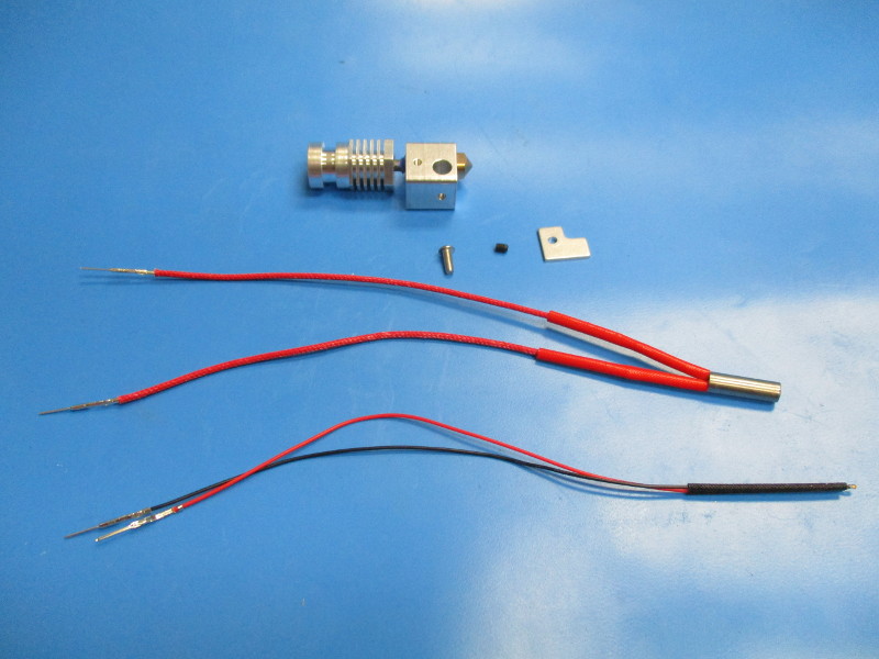
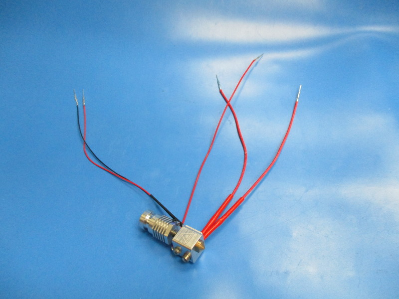
Hot end assembled
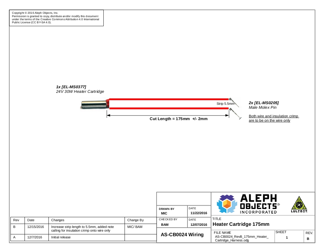
Heater cartridge harness, 175mm [AS-CB0024]
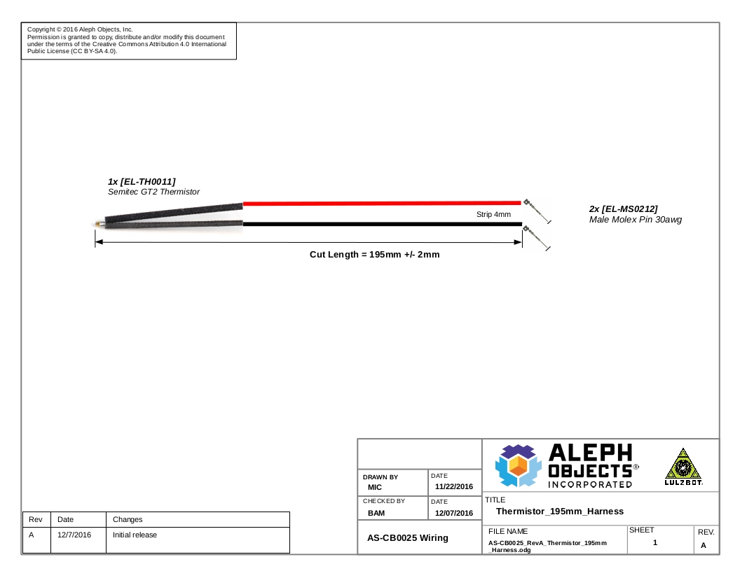
Thermistor harness, 195mm [AS-CB0025]
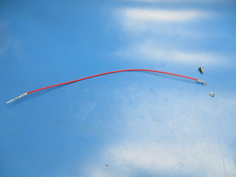
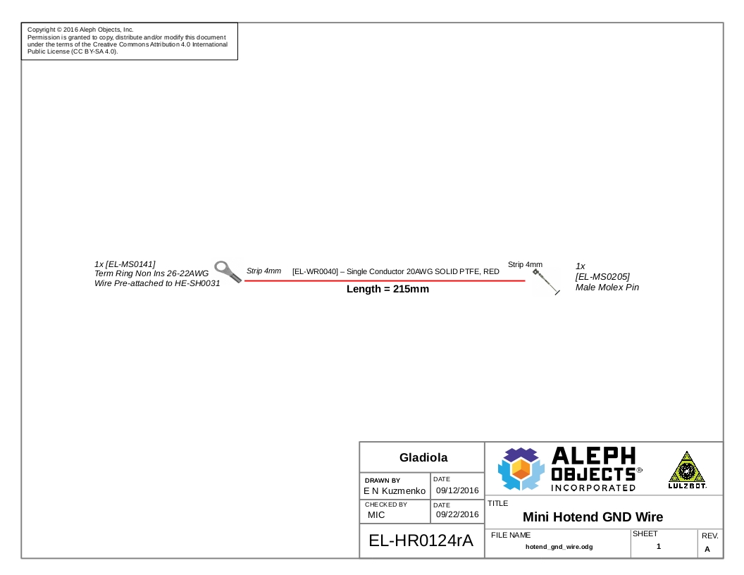
Hot End Ground Wire [EL-HR0124]
Retention plate (PP-MP0136)
Set screw (HD-BT0172)
M3x8 BHCS (HD-BT0104)
Tools needed: 2mm hex driver
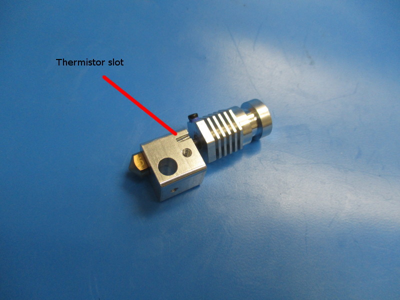
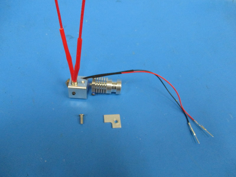
Lay the hot end on its side so the thermistor slot is facing up. (see image “thermistor slot” for orientation)
Insert the heater cartridge into the large hole.
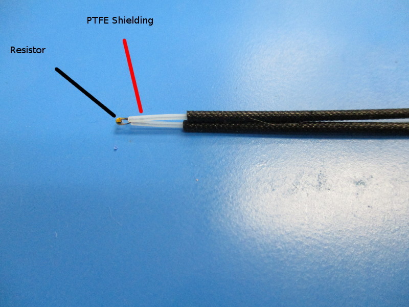
Take the thermistor and slid the black shielding back. Ensure the white PTFE shielding is completely covering the wires running into the resistor or thermistor.
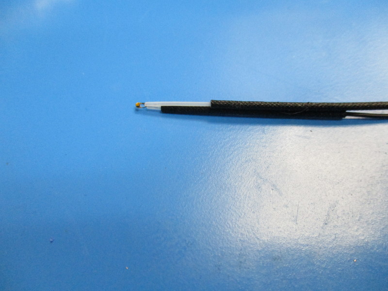
Slide one of the black shieldings back until there is 5mm of white PTFE showing.
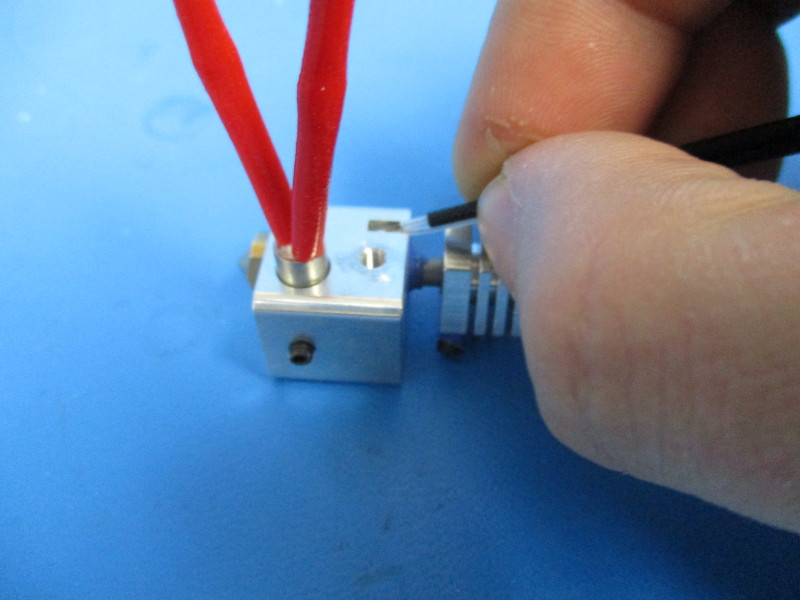
Insert the thermistor into the thermistor slot on the heater block. The side of the thermistor harness with less exposed PTFE shielding will sit up against the heater block (see image “Inserting thermistor” and “Thermistor inserted”)
Install the retention plate onto the side of the heater block that has the harnesses installed.
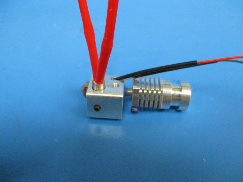
Ensure the retention plate is lined up with the edge of the heater block. (see image “Retention plate aligned”) Torque to 4in*lbs
Rotate the hot end so that the front of the hot end is facing down. (see image “ hot end orientation”)
Install the set screw into the threaded hole on the heater block. Ensure the heater cartridge is up against the retention plate. Use the 1.5mm driver to finger tighten the set screw to secure the heater cartridge.
Flip the hot end so that the set screw is facing down.
Gather parts
Mini Zero Sense 215mm Harness [EL-HR0124]
M3x8 BHCS (HD-BT0104)
External star washer (HD-WA0027)
Tools needed: 2mm hex driver
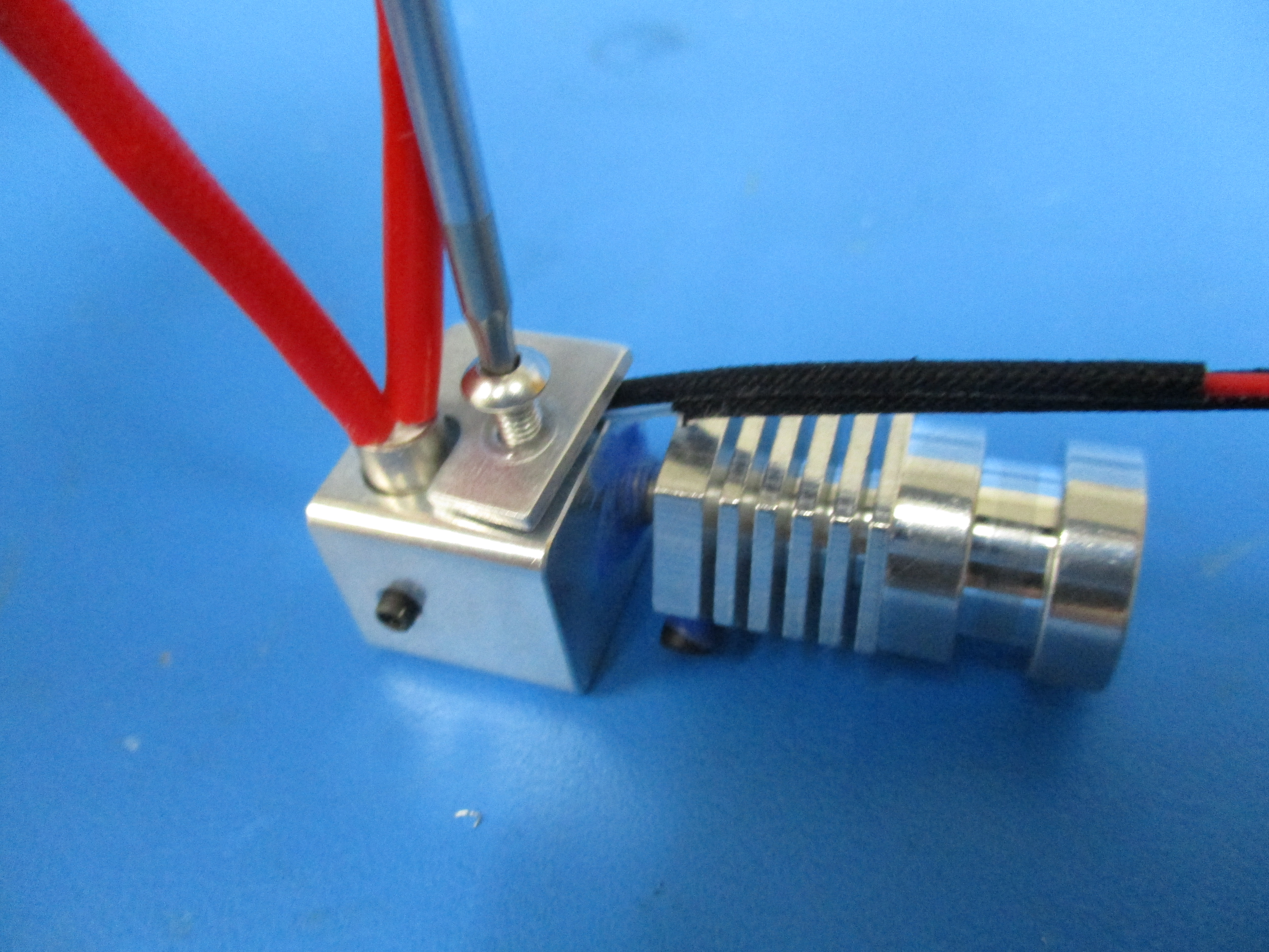
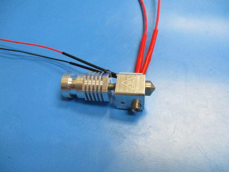
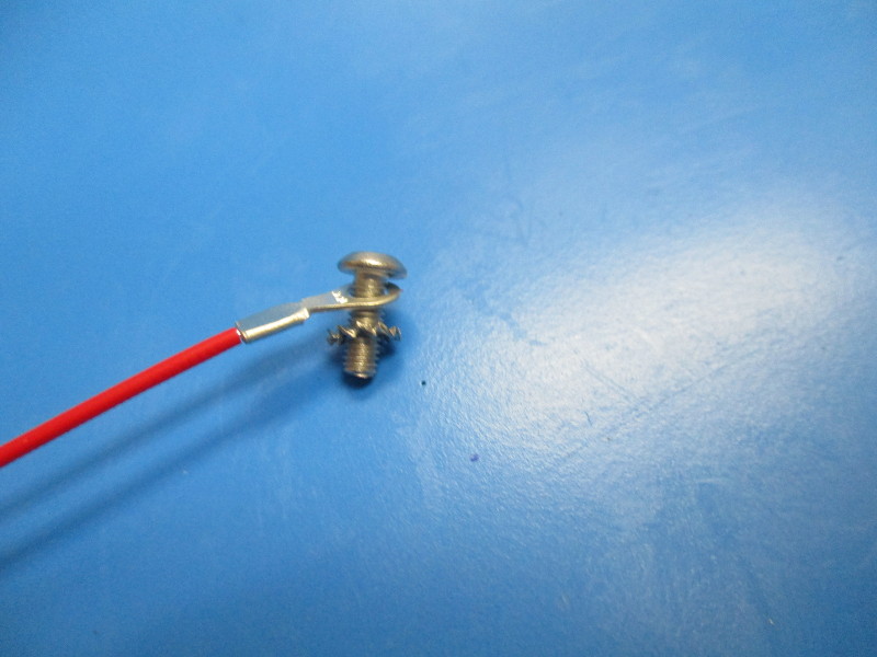
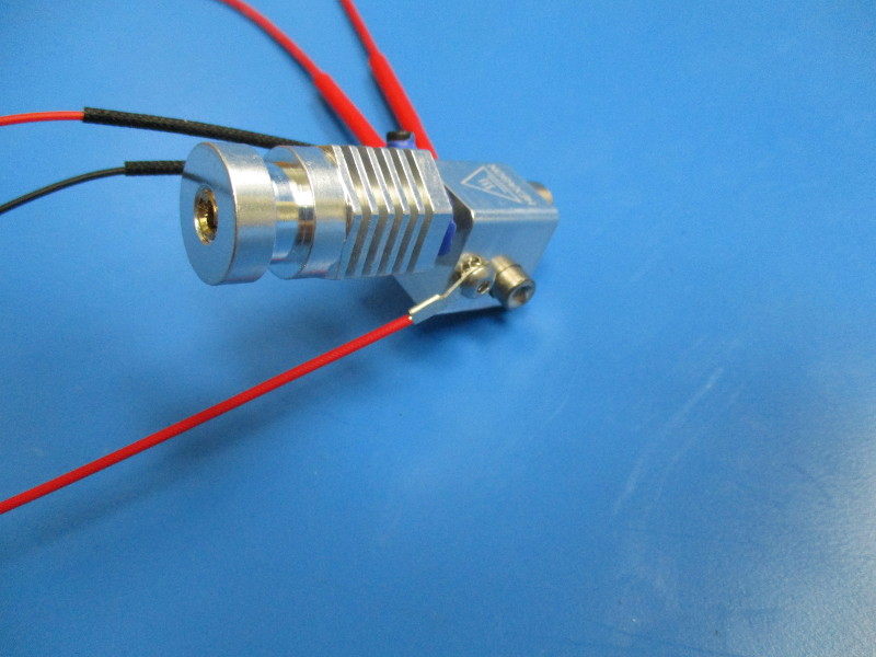
Install the zero volt sense harness onto the M3x8 BHCS followed by the star washer. (see image “Component installation order”)
Install the zero volt sense harness and components onto the heater block. (see image “Zero volt sense harness installation”)
Torque to 4in*lbs
Bend the wire so that it runs behind the heat break. Ensure that the wire is not touching the heater block.
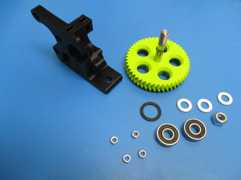
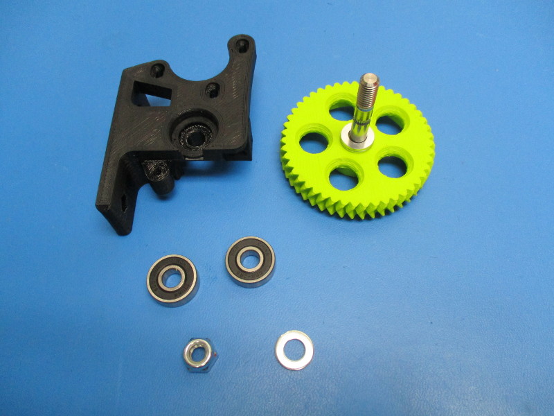
Gather parts
1x Extruder body (PP-GP0186)
1x large herringbone (AS-TH0003)
1x extruder washer (PP-GP0060)
3x- M8 zinc plated washer (HD-WA0006)
2x- 608 bearing (HD-MS0282)
1x- M8 nyloc nut (HD-NT0002)
4x- M4 nut (HD-NT0011)
Tools required: 13mm wrench
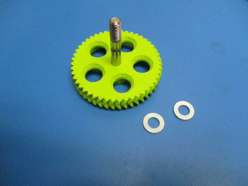
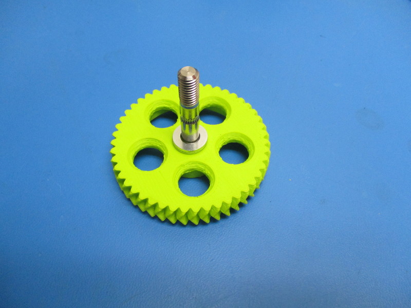
Start with the large herringbone gear
Place two M8 washer onto the hobbed bolt, that has been pressed into the large herringbone gear
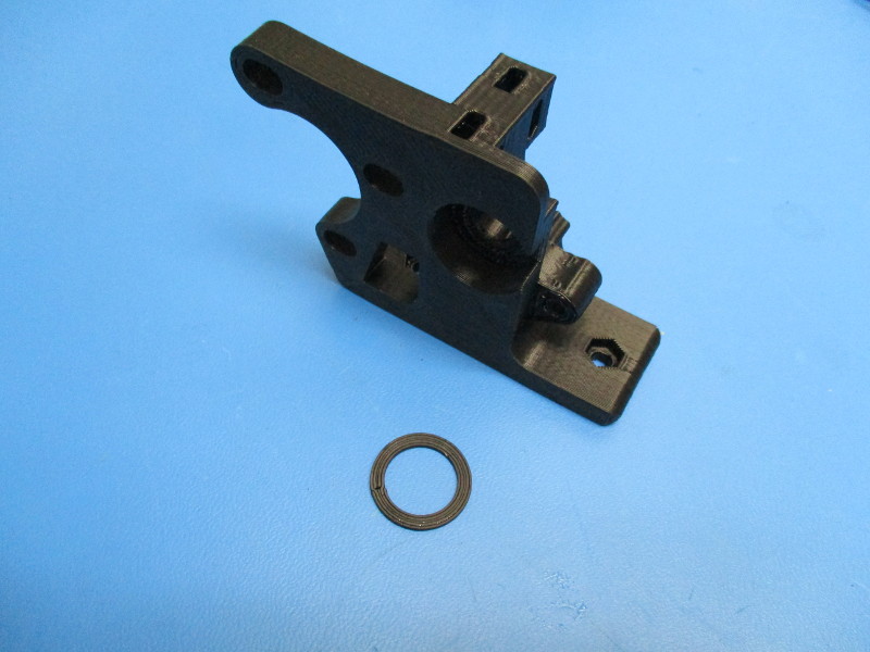
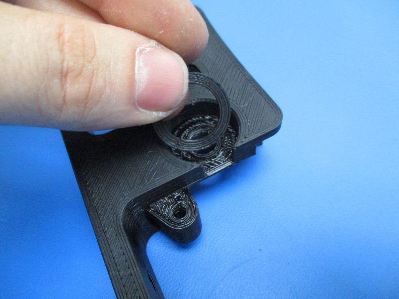
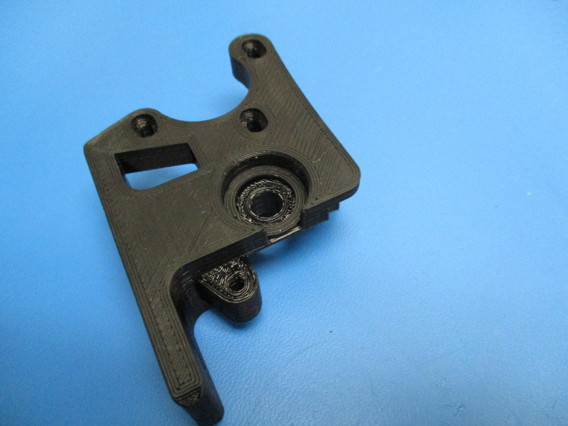
-Placing the extruder washer into the body
Lay the body on its side with the smooth surface facing up. Place the extruder washer into the bearing slot.
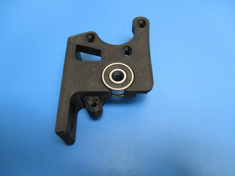
Place 608 bearing into the bearing slot.
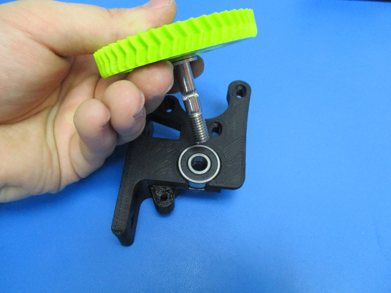
Install the large herringbone gear with washers by inserting the hobbed bolt portion into the 608 bearing and through the body.
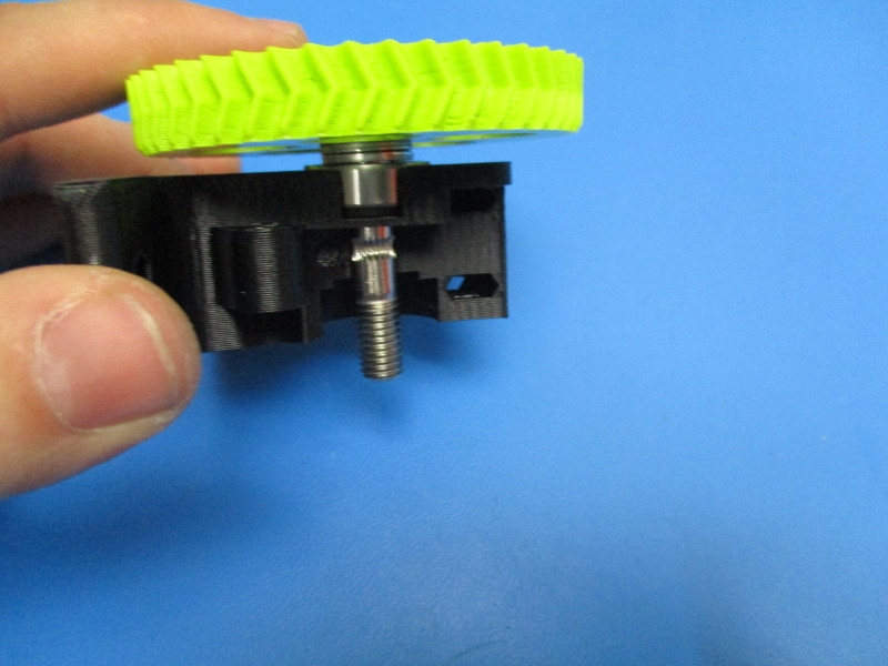
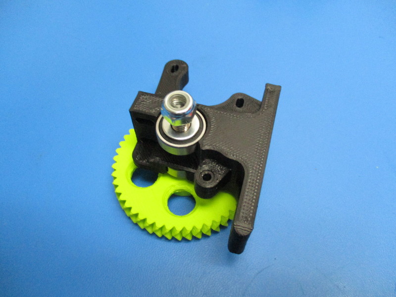
Rotate the body so that it rests on the large herringbone gear. Install the second 608 bearing onto the threaded portion of the hobbed bolt. Slide the bearing down so that it sits against the body.
Slide an M8 washer over the hobbed bolt so that it lays on top of the 608 bearing.
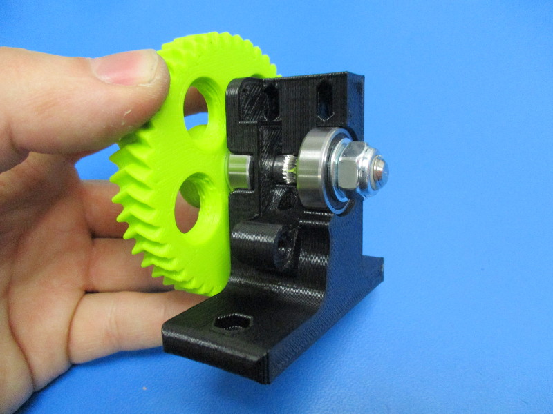
Thread the M8 nyloc nut onto the threaded portion of the hobbed bolt.
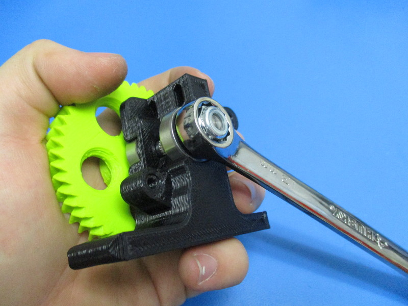
CAUTION: Over-tightening the M8 nyloc nut can cause the extruder body to fracture. Tighten the M8 nyloc nut down using a 13mm wrench
Tighten the M8 nyloc nut to where it is snug against the M8. (A good way to test to see if the nyloc nut is tight enough is to push the M8 washer under it with your thumb nail, if it moves then it needs to be tightened more)
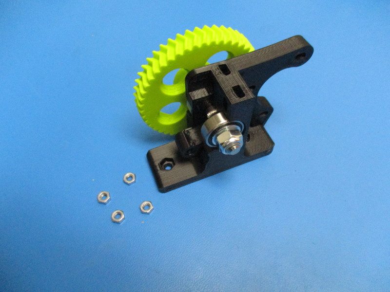
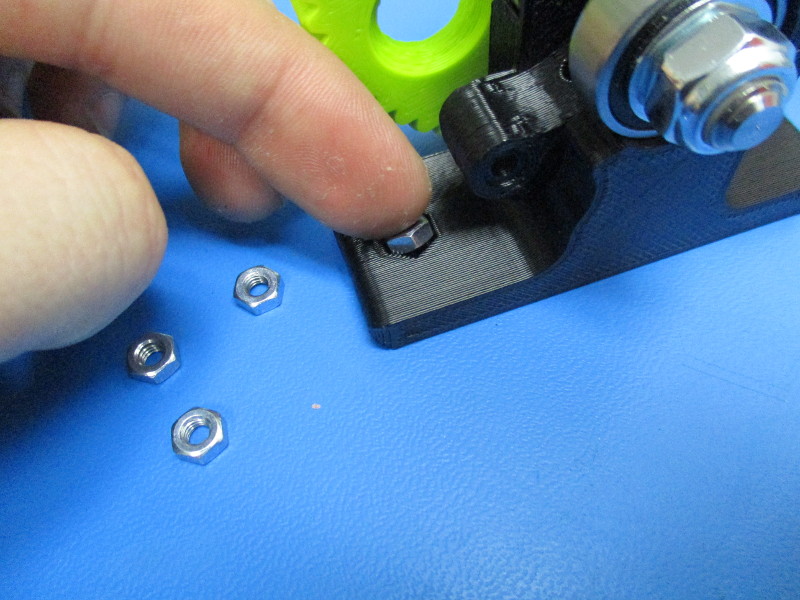
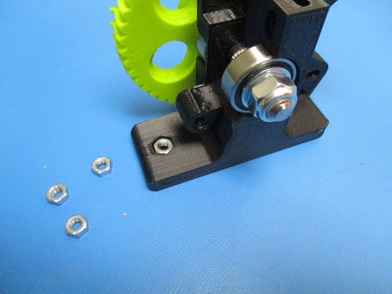
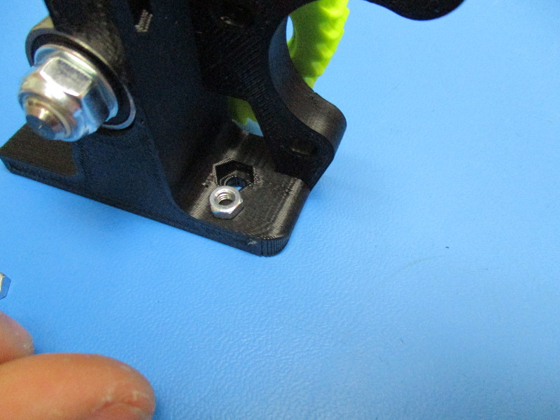
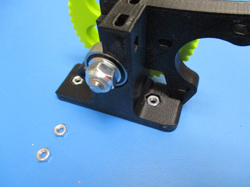
Install the M4 nuts Place on nut into the nut slot on the left of the body
Place nut into the slot on the right side of the body
On the top of the extruder body there are two slots for the M4 nut Place a nut in each slot as shown ( press nut into slot if necessary)
Gather parts
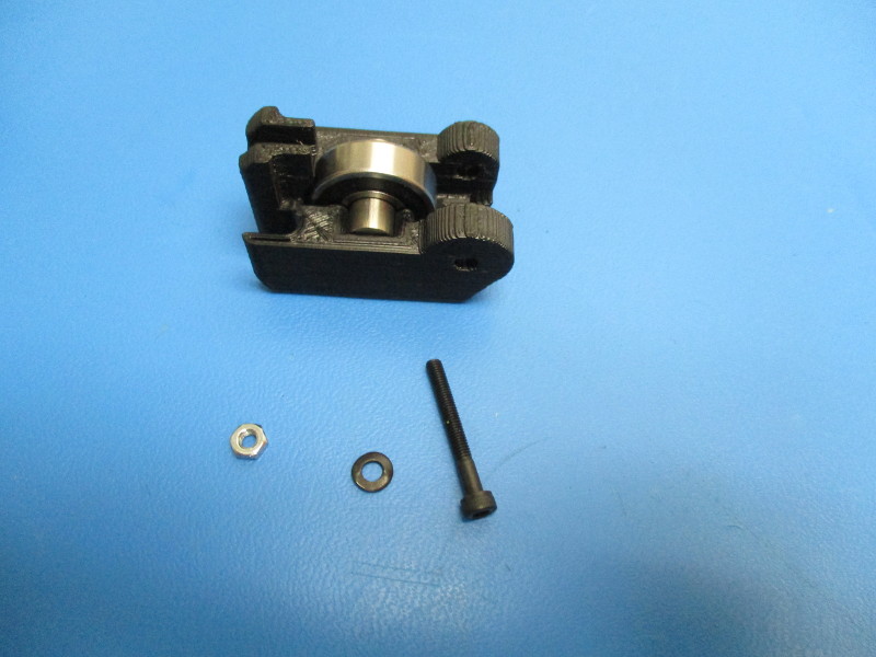
Idler block (AS-TH0028)
M3 nut (HD-NT0004)
M3 black oxide washer (HD-WA0038)
M3x25 SHCS (HD-BT0041)
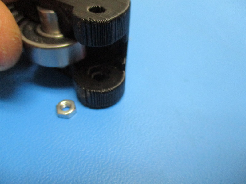
Rotate the idler block so that the hexagon shaped cavity is facing up
Insert the M3 nut into the hexagon cavity
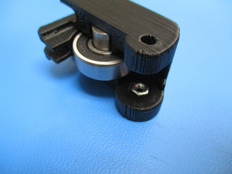
Rotate the idler block upright as shown
Thread M3x25 screw with the black oxide washer through the left side hole in the idler block and into the M3 nut ( thread just enough that the M3x25 screw is flush on the exposed side of the M3 nut)
Installing the idler block
Tools needed: 2.5mm hex driver
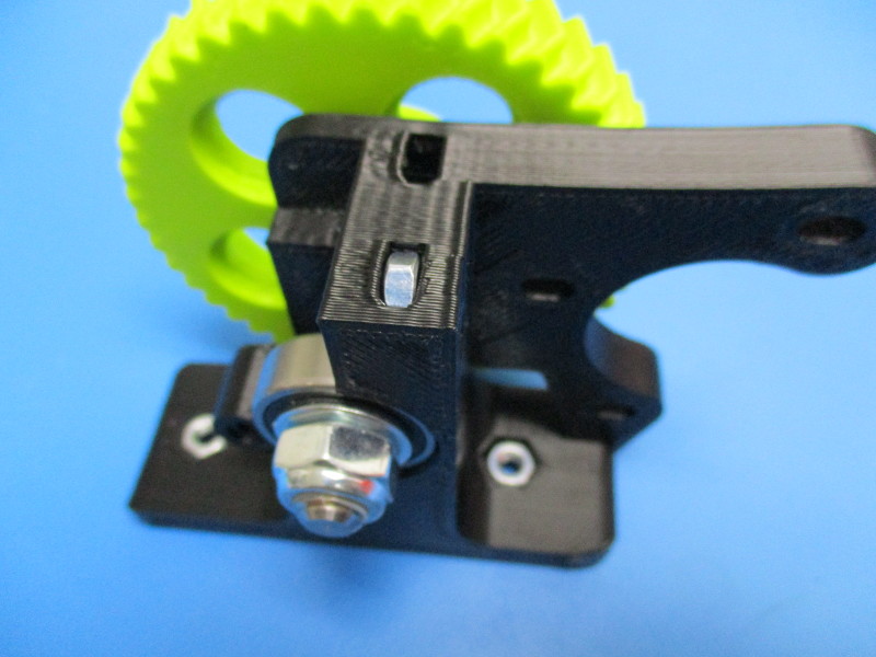
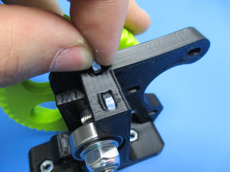
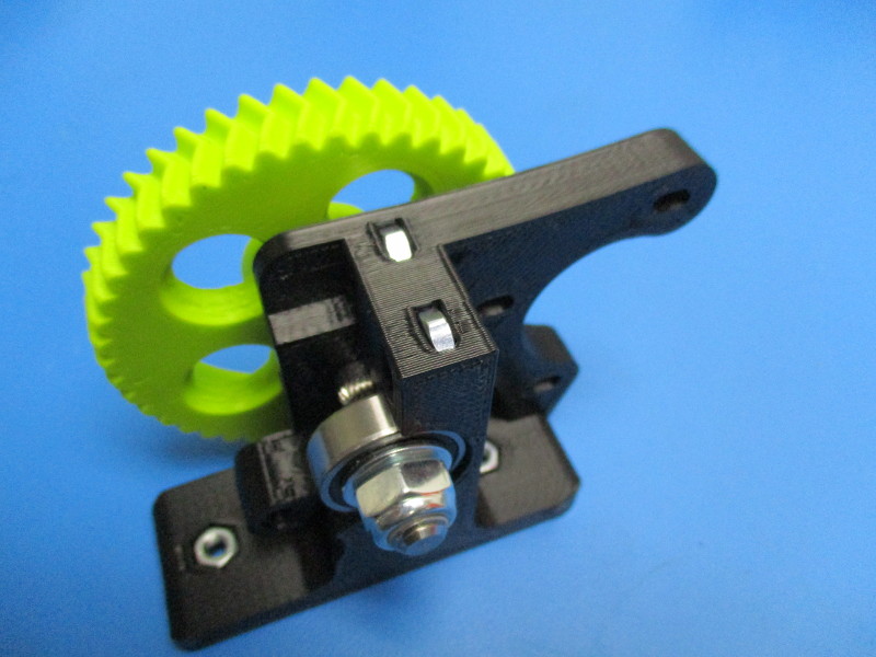
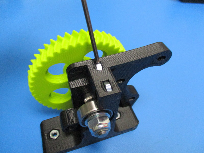
Line the idler block up with the body ( see image for orientation)
Slide the idler block into place
Tighten down using a 2.5mm driver Torque to 3in*lbs
Gather parts
1x- extruder latch (PP-GP0245)
4x- M4 black oxide washers (HD-WA0039)
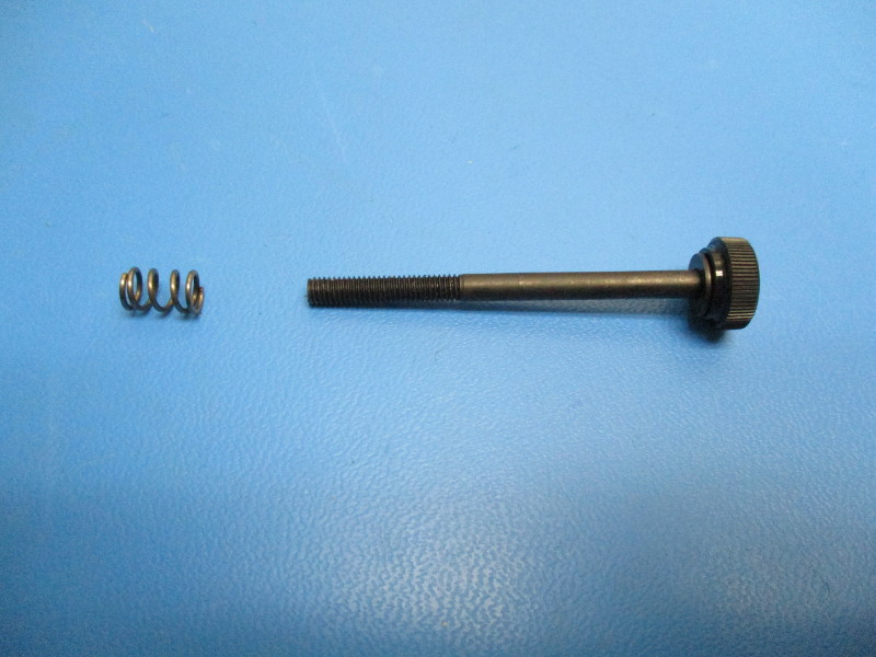
2x- extruder spring (HD-MS0027)
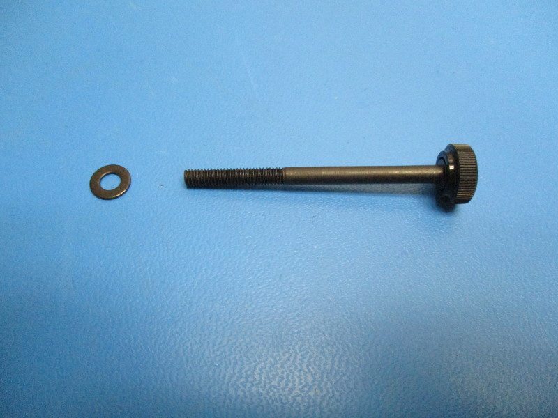
2x- thumb screw (assembly)
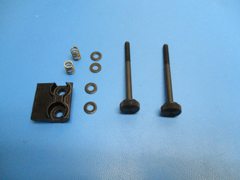
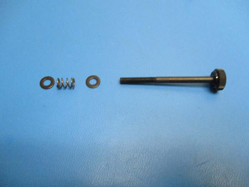
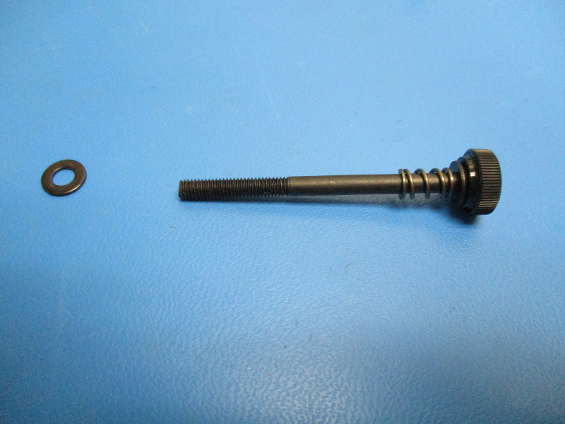
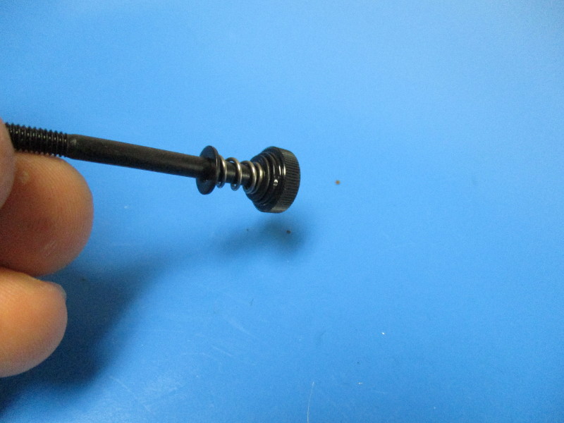
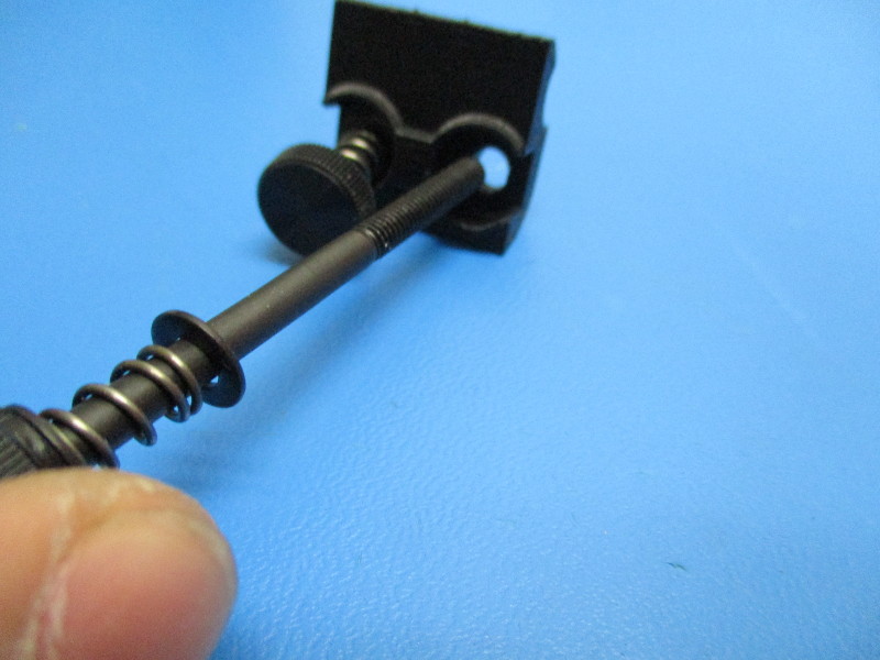
Components will need to be installed onto the thumb screw in this order: M4 washer, spring, M4 washer
Repeat the process for a second thumb screw with components installed
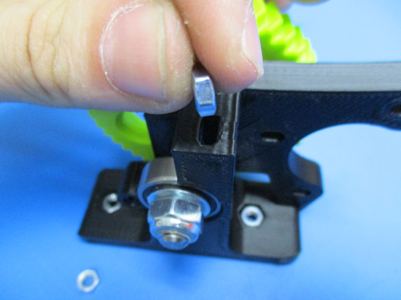
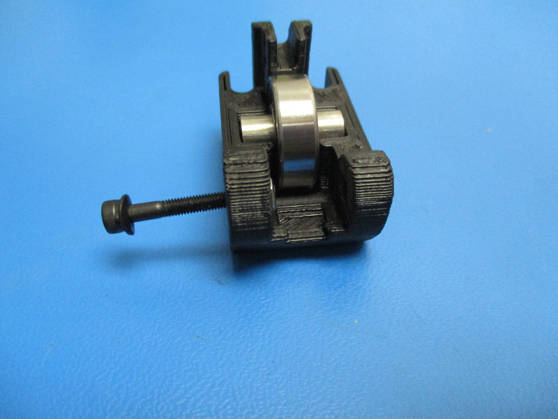
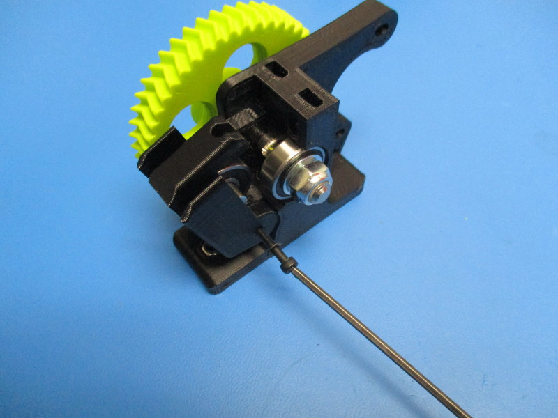
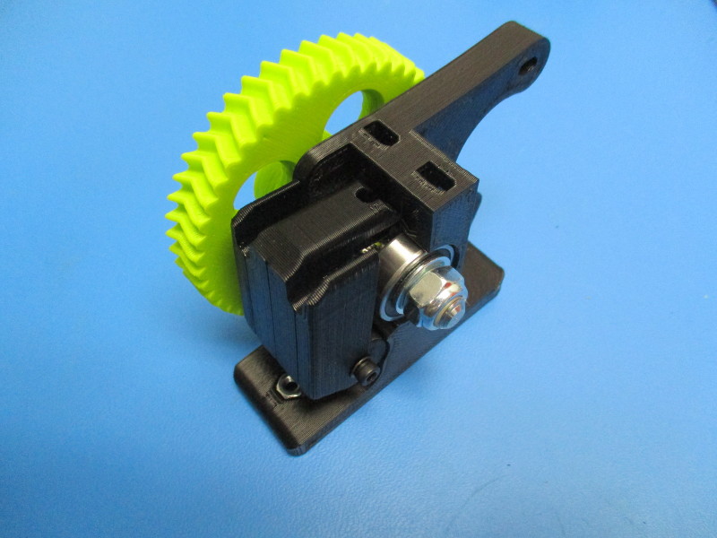
Install the thumb screws into the extruder latch ( see image “Finished extruder latch” for orientation of latch)
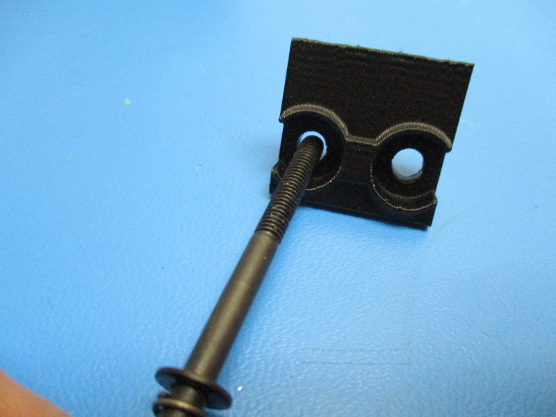
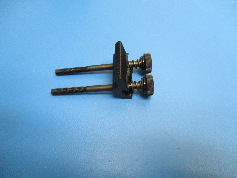
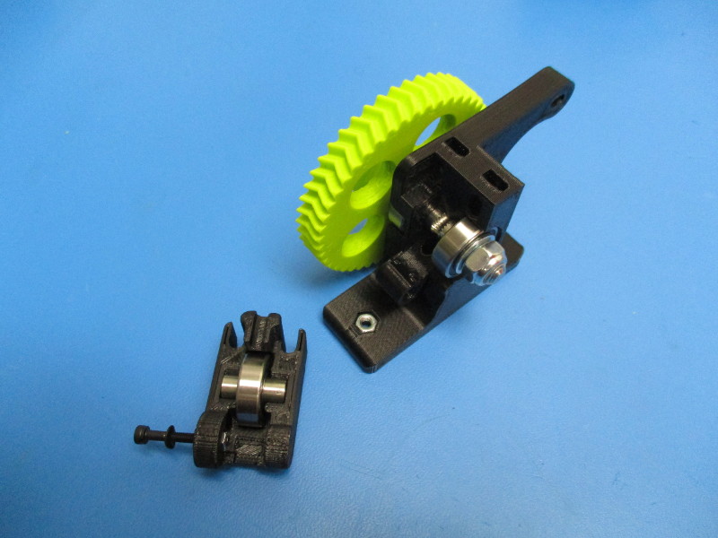
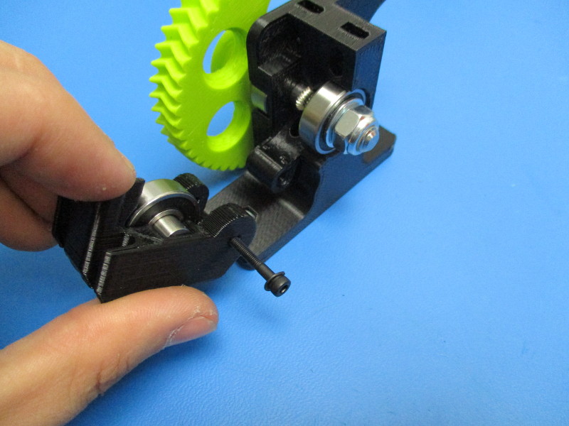
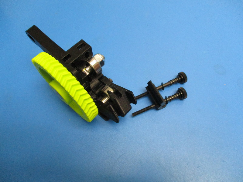
Line the extruder latch up with the slots in the idler block when it is sitting upright in the closed position. (see image “Latch sitting in idler block” for latch orientation)
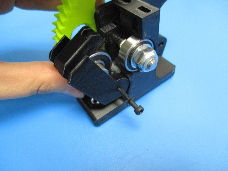
Thread the thumb screws into the holes with the M4 nuts that were previously installed
The thumb screws don't need to be tightened all the way, leave them loose for now.
Small herringbone prep
Gather parts
Small herringbone gear, green (PP-GP0192)
M3 set screw (HD-BT0012)
M3 nut (HD-NT0004)
Tools needed: 1.5mm hex driver
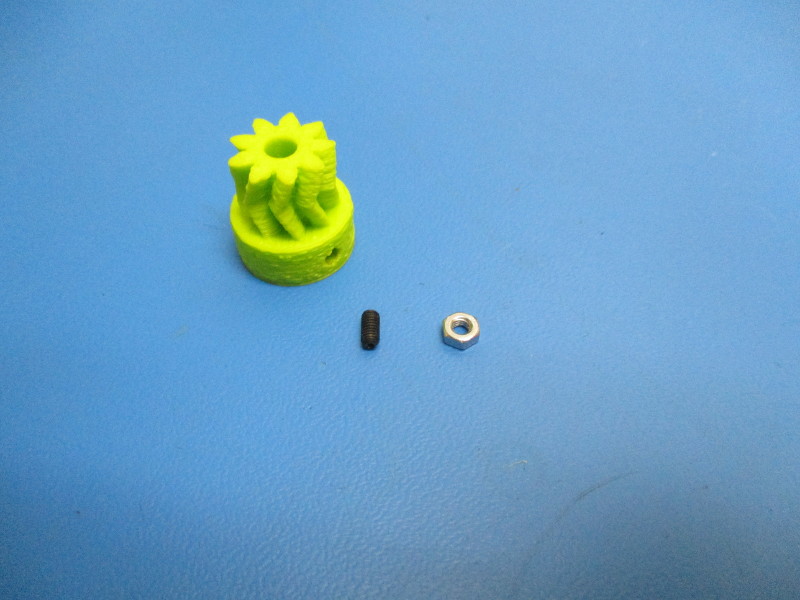
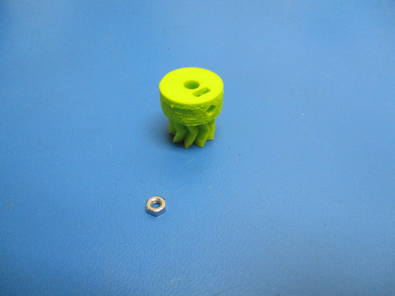
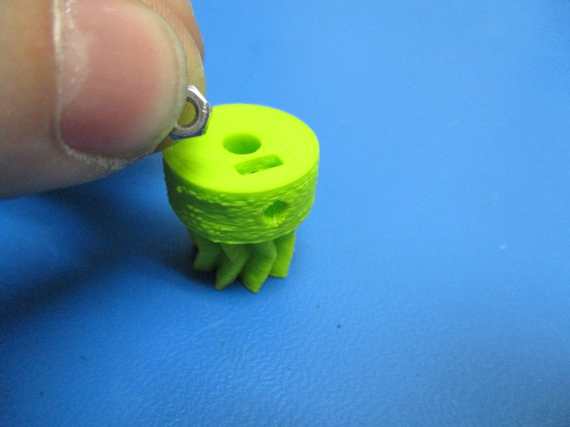
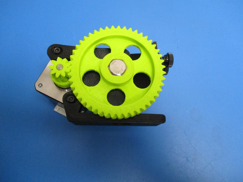
Start by laying the small herringbone gear is sitting with the nut slot facing up (see image for gear orientation)
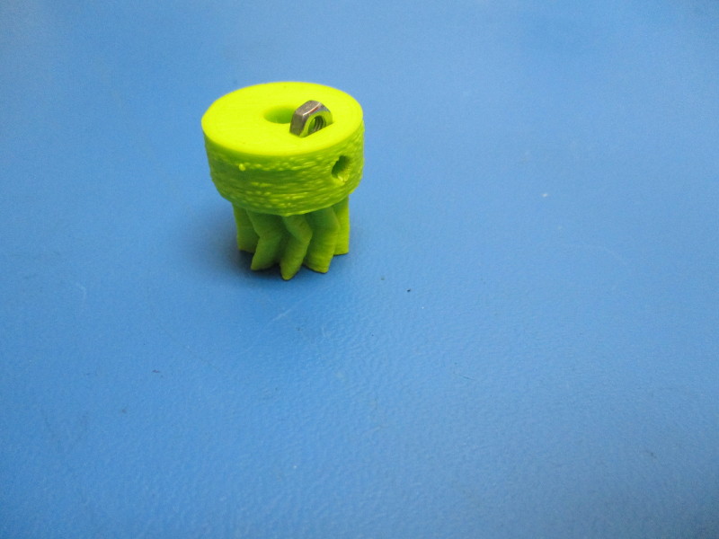
Press nut into slot until holes in the small gear and the nut line up.
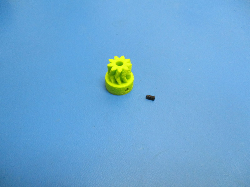
Rotate the gear so that the slot is facing down
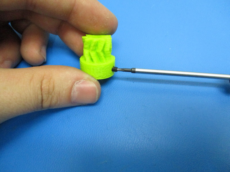
Install the set screw into the hole that is aligned with the nut using a 1.5mm driver Tighten until the head of the set screw is flush with the plastic
Gather parts
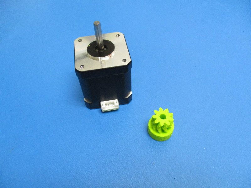
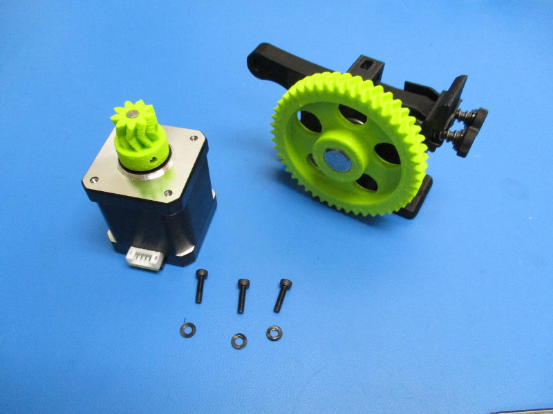
Moons motor (EL-MT0029)
Small herringbone gear (assembled)
Tools needed: 1.5mm hex driver
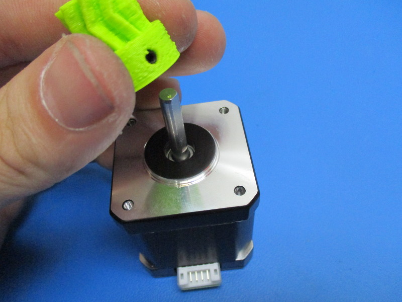
Install the small herringbone gear onto the shaft of the motor. Ensure that the set screw is aligned with the flat section of the shaft.
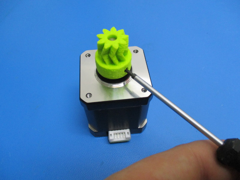
Finger tighten the set screw up to the shaft by using the 1.5mm driver.
Final body assembly
Gather parts
3x- M3x12 SHCS (HD-BT0039)
3x- M3 black oxide washer (HD-WA0038)
1x- Moons motor with small herringbone
1x- Extruder body (partially assembled)
Tools needed: 2.5mm hex driver
1.5mm hex driver
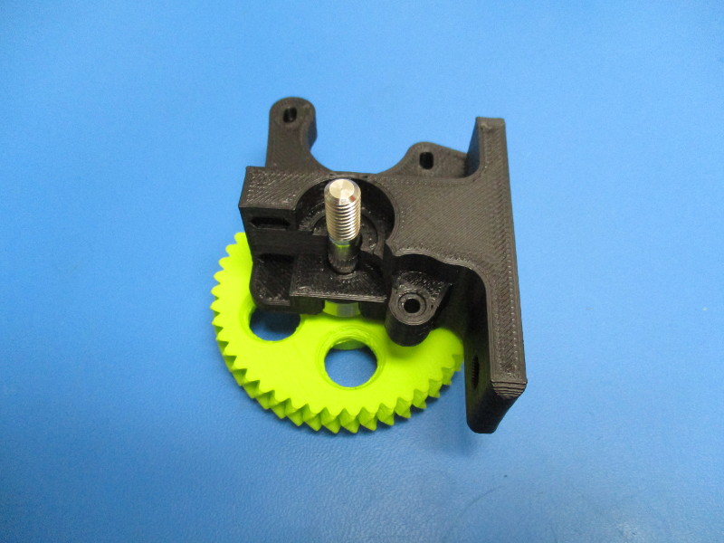
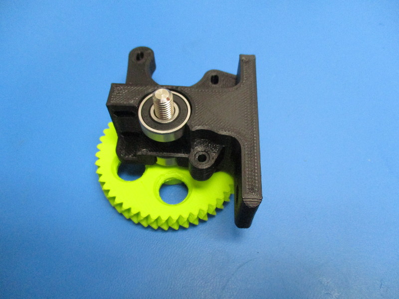
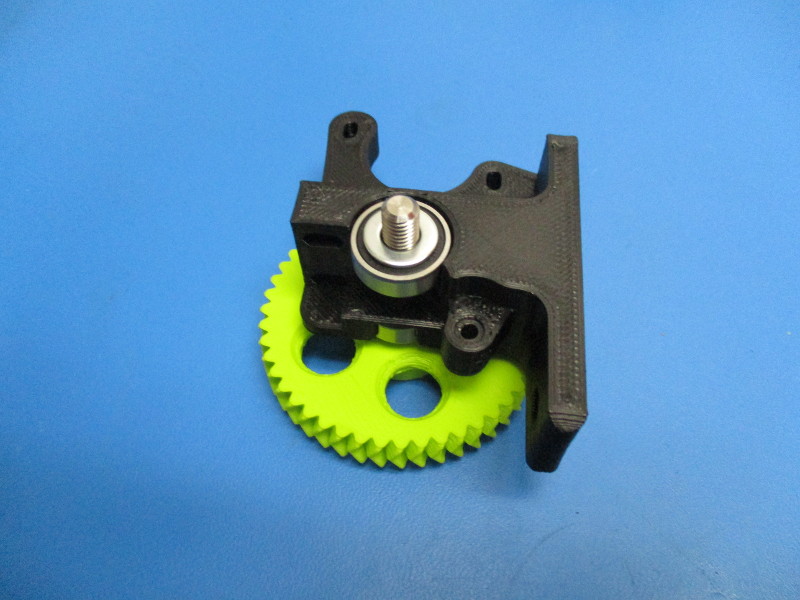
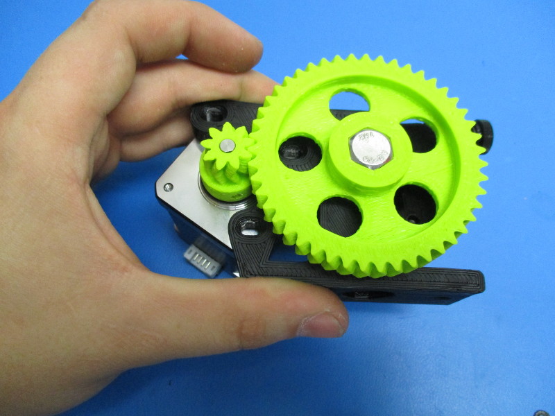
Mount the motor to the body (note the orientation of the motor and harness connection point)
Place the M3x12 SHCS with black oxide washers in the three holes that line up with the tapped holes in the motor
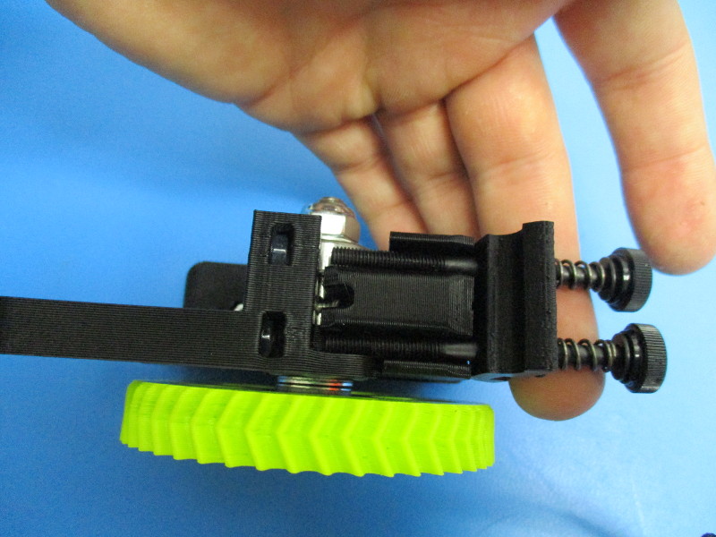
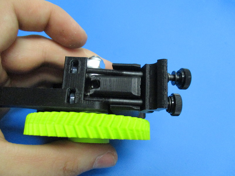
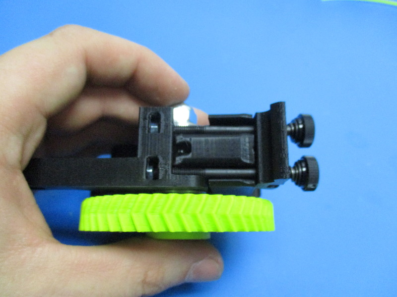
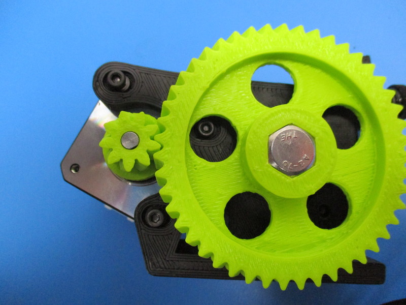
Note: the large gear and the small gear need to be mated together in a way that there is easy rotation but won't have any free movement known as “slap” between the gear teeth. To test for proper alignment of gears - tighten your screws down to 3 in/lbs, Hold the small gear firmly with your finger and thumb, and try to move the large gear back and forth to see if there is any small movement between the teeth of the gears. Rotate the large gear ¼ turn and repeat this process multiple times to ensure alignment. If there is movement the small gear and large gear need to be moved closer to each other. To do this you need loosen the M3 screws ¼ turn counter-clockwise and push the motor closer to the body. Repeat until you have desired the results, tighten screws once the fit is correct.)
Tighten the set screw in the small herringbone gear to 2in*lbs
Gather Parts
1x- Extruder body (assembled)
1x- hot end (assembled)
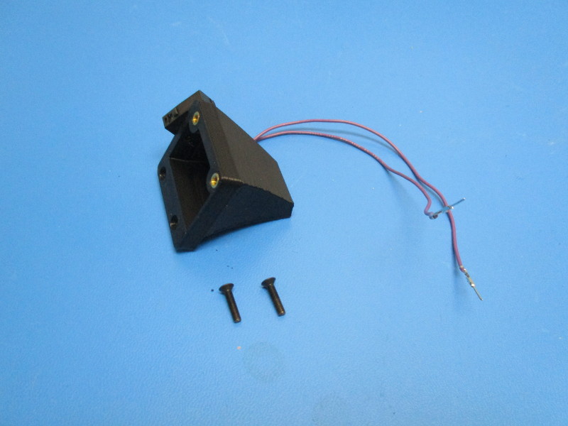
1x- mount plate (PP-MP0156)
1x- Extruder mount (AS-TH0027)
2x- M4x25 SHCS (HD-MS0229)
2x- M4 black oxide washer (HD-WA0039)
Tools needed: 3.5mm hex driver 150mm of 3mm ABS filament
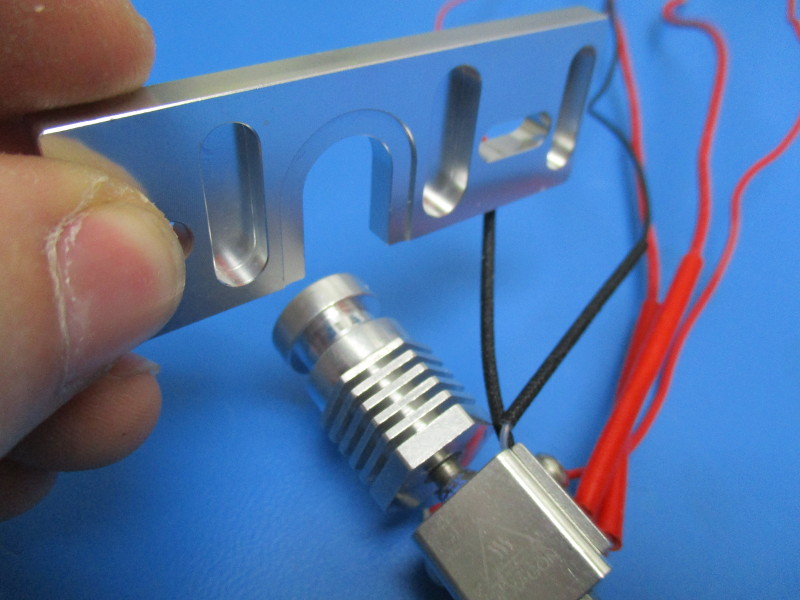
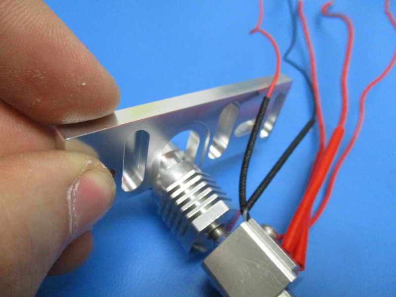
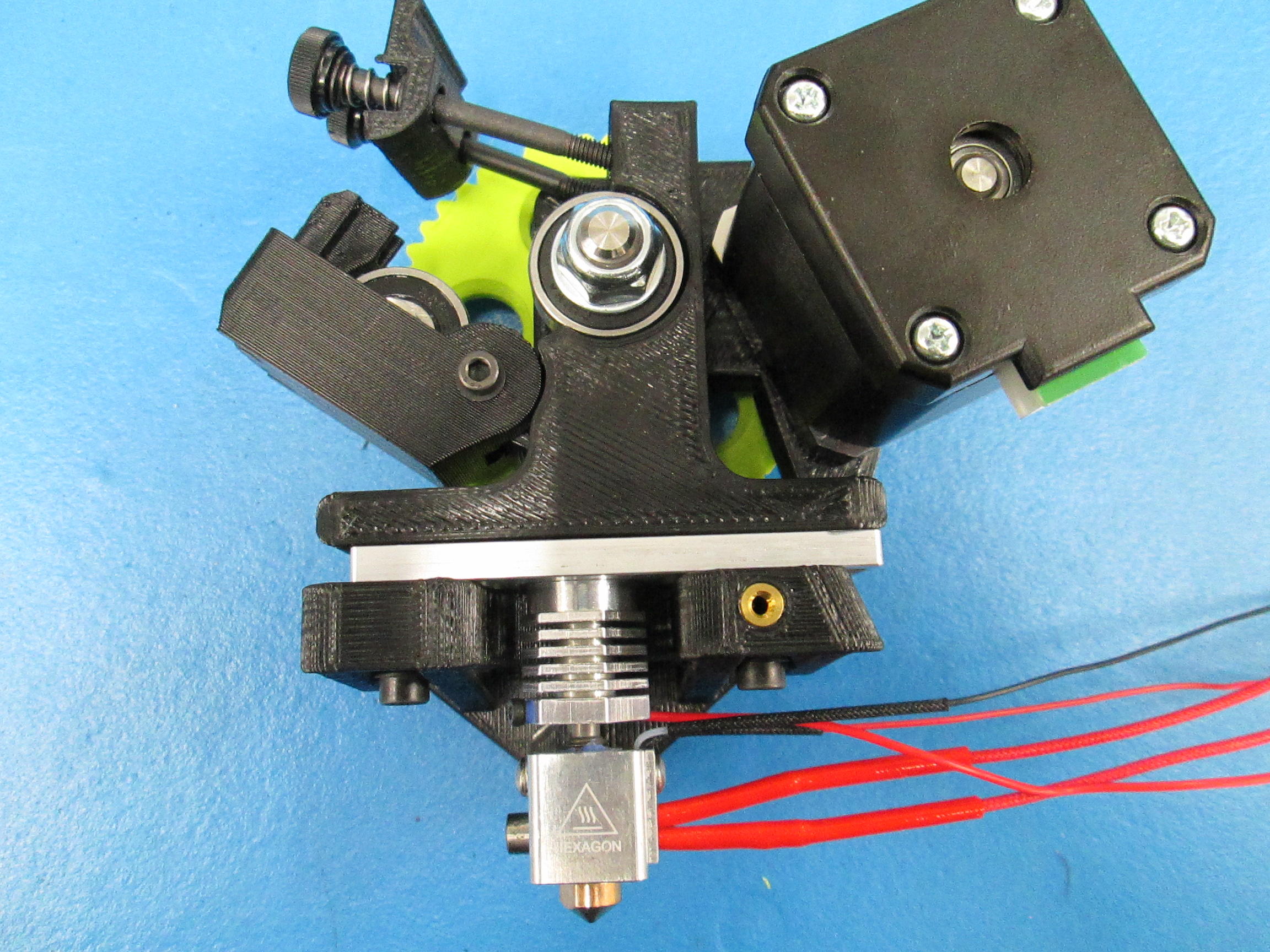
Slide the mount plate over the grooved section of the heat sink on the hot end. ( see image “Installing mount plate onto hot end” for mount plate orientation and heat sink orientation)
Take the hot end with the mount plate attached and slide it onto the extruder mount (see image “Extruder mount orientation” for extruder mount orientation)
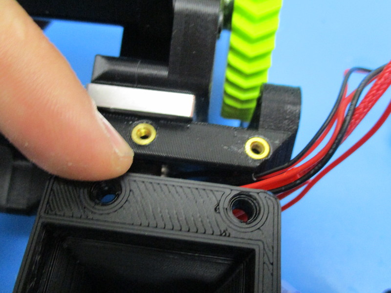
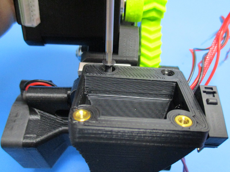
Insert M4x25 screws with M4 washers into the holes in the front of the extruder mount and through the slots in the mount plate.
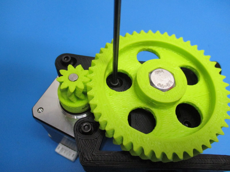
Take the body and run the piece of filament through the filament hole. The filament should be sticking out of both the top and the bottom. Line the body up with the extruder mount. The screws in the extruder mount should align with the M4 nuts in the body assembly and the filament will slide into the hot end. (see image “Body and hot end ready to be mounted” for reference)
Tighten the M4x25 screws to 8in*lbs
Ensure that the hot end is square with the extruder mount and mount plate
Gather parts
1x- 5v 40mm fan (EL-HR0123)
1x- heatsink fan mount (AS-TH0016)
4x- M3x12 SHCS (HD-BT0039)
1x- M3x25 (HD-BT0041)
1x- M3 black oxide washer (HD-WA0038)
Tools needed: 2.5mm hex driver
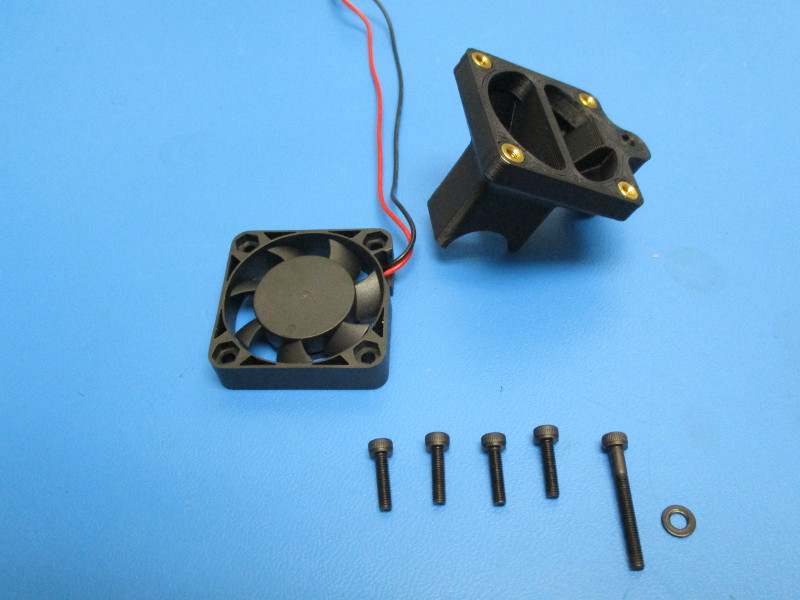
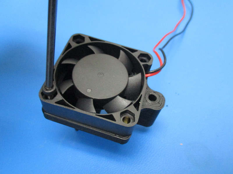
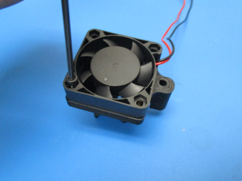
Place the 5v fan onto the heat sink fan mount so that the holes align (see image “Fan and heatsink orientation” for mount and fan orientation)
Insert M3x12 SHCS into the four corners of the fan and torque to the heat sink fan mount at 3in*lbs
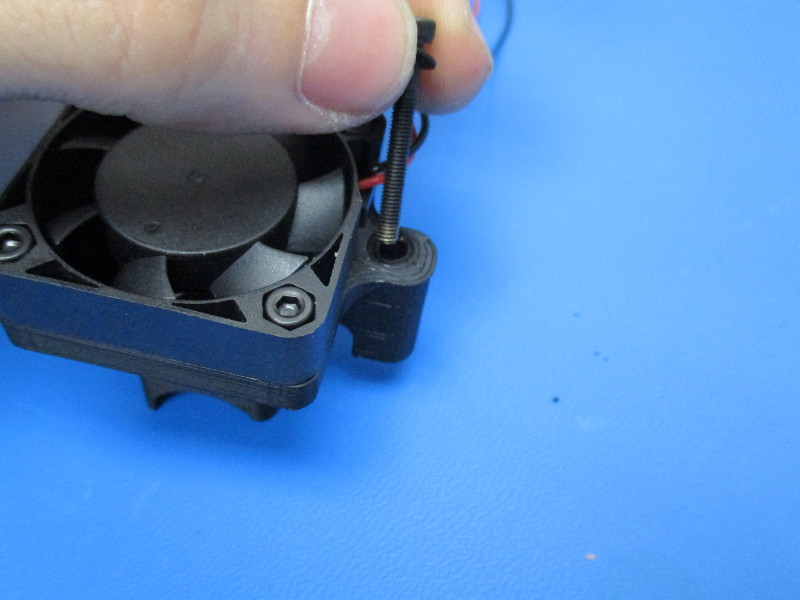
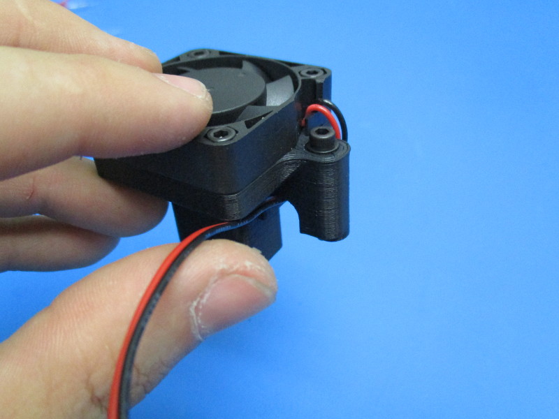
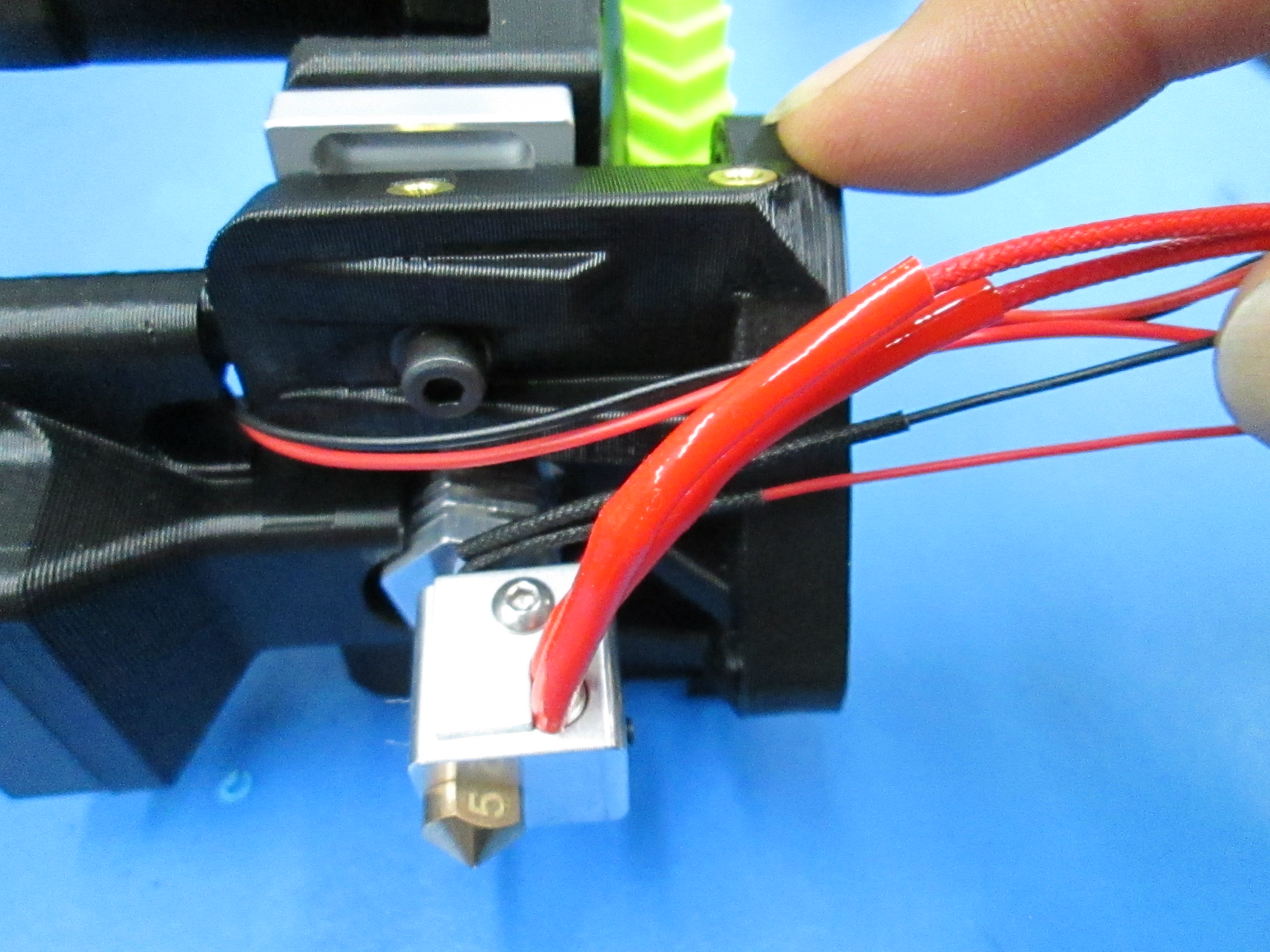
Insert M3x25 SHCS with a black oxide washer into the side hole of the fan duct
Wrap the fan harness down the side of the fan and under the M3x25
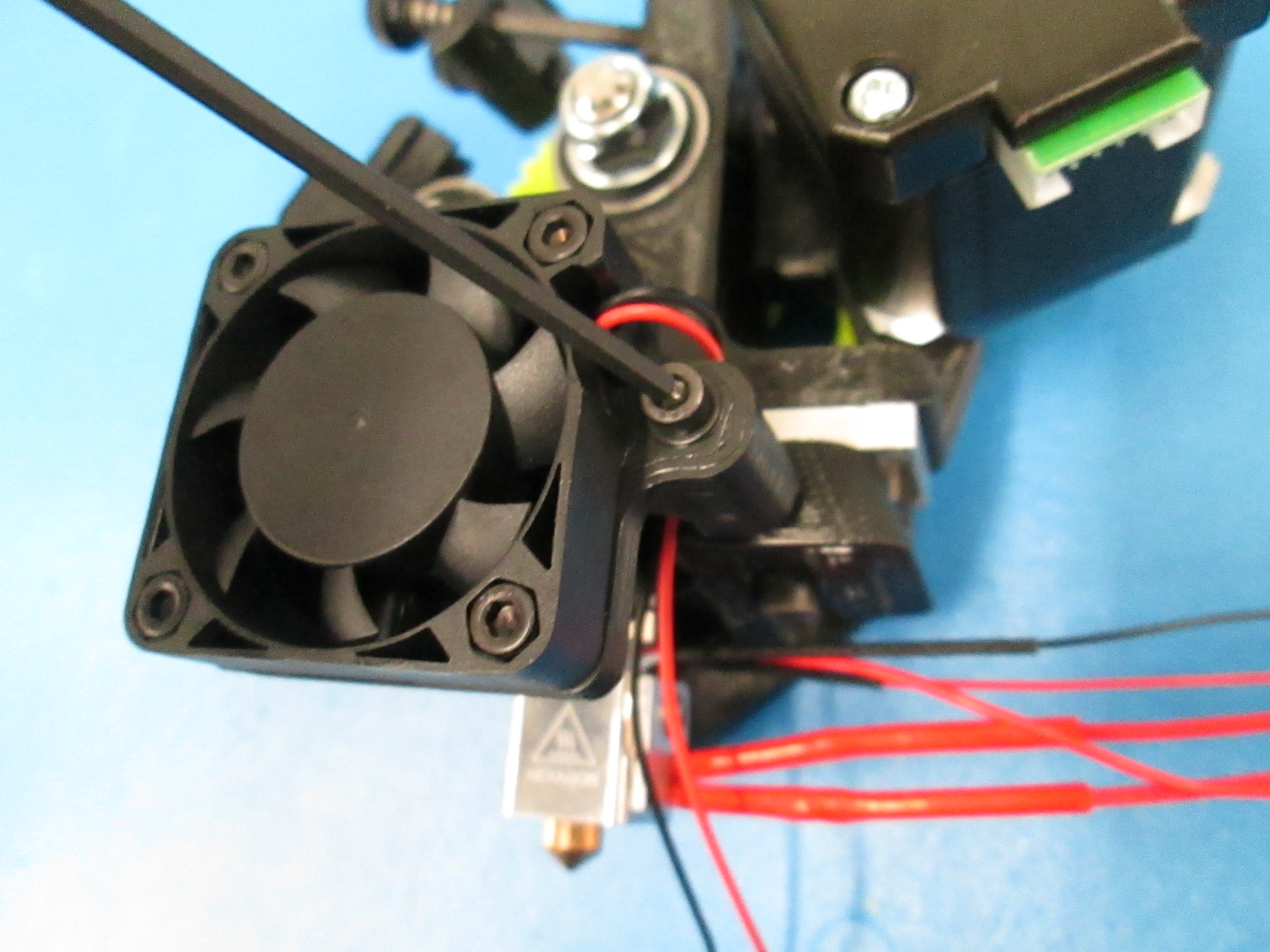
Install the fan mount onto the extruder mount by aligning the M3x25 with the threaded insert on the front of the mount (see image “mounting heatsink to mount) Torque to 2in*lbs
Gather parts
1x- end stop switch (EL-SW0022)
2x- M2x10 SHCS (HD-BT0107)
2x- M2 washer (HD-WA0012)
1x- extruder fan duct (AS-TH0023)
-2x- end stop switch harness
Tools needed: 2mm hex driver
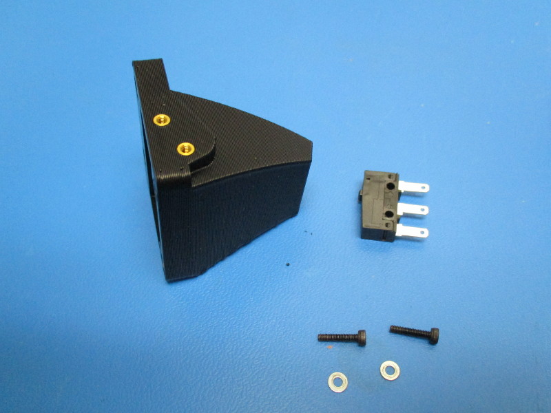
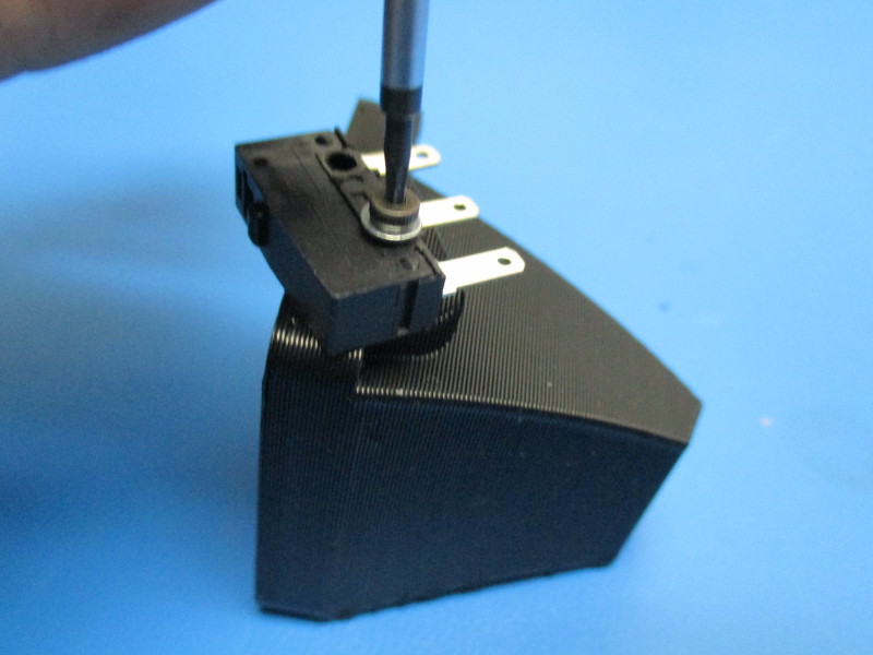
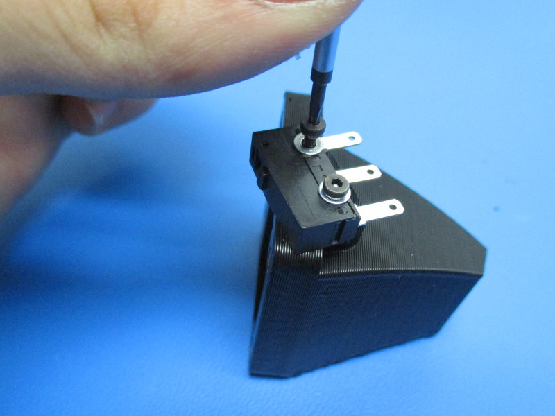
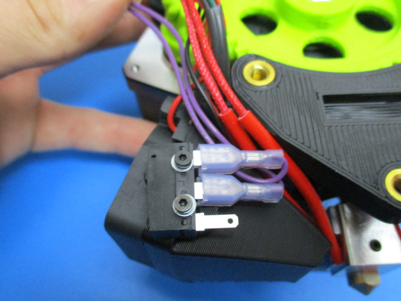
Align the holes in the end stop switch with the small threaded inserts on the side of the fan mount. (see image “attaching switch” for orientation of switch and fan duct) Install the M2x10 screws to attach the switch to the fan mount, torque to 2in*lbs
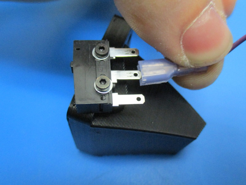
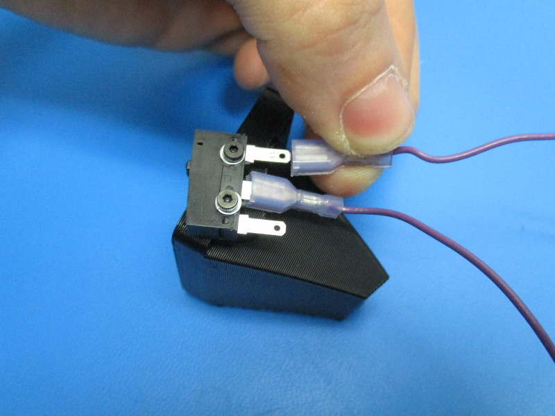
Attach the switch harness wires to the middle prong and top prong (see image “top prong")
Gather parts
1x- extruder fan duct with switch harness
2x- M3x14 FHCS (HD-BT0118)
Tools needed: 2mm hex driver
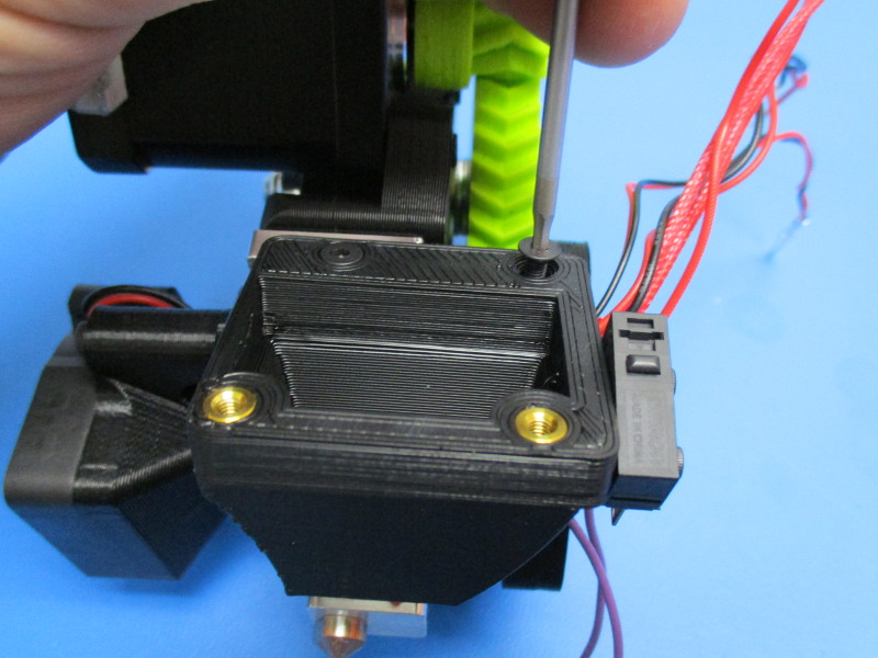
Note: All harnesses on the extruder need to be pulled towards the back before mounting the extruder fan.
Line up the counter sunk holes on the extruder fan mount with the threaded inserts on the extruder mount.
Attach the extruder fan duct to the extruder mount with the M3x14 FHCS using the 2mm hex driver. Torque to 3in*lbs
Gather parts
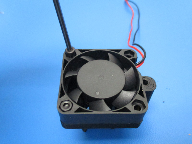
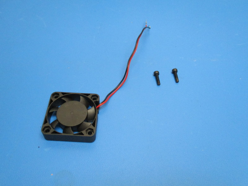
1x- 24v 40mm fan (EL-HR0121)
2x- M3x12 SHCS (HD-BT0039)
Tools needed: 2.5mm hex driver
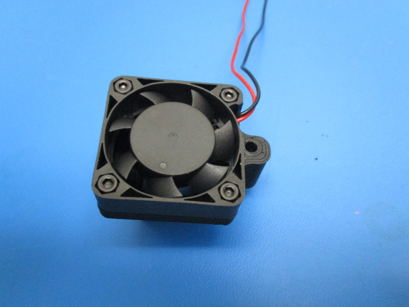
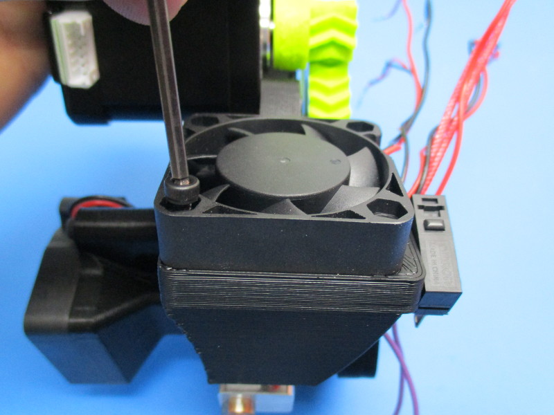
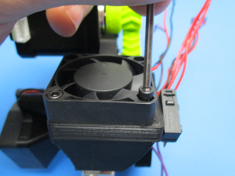
Orient the fan on the extruder fan mount so that the wires come out on the switch side.
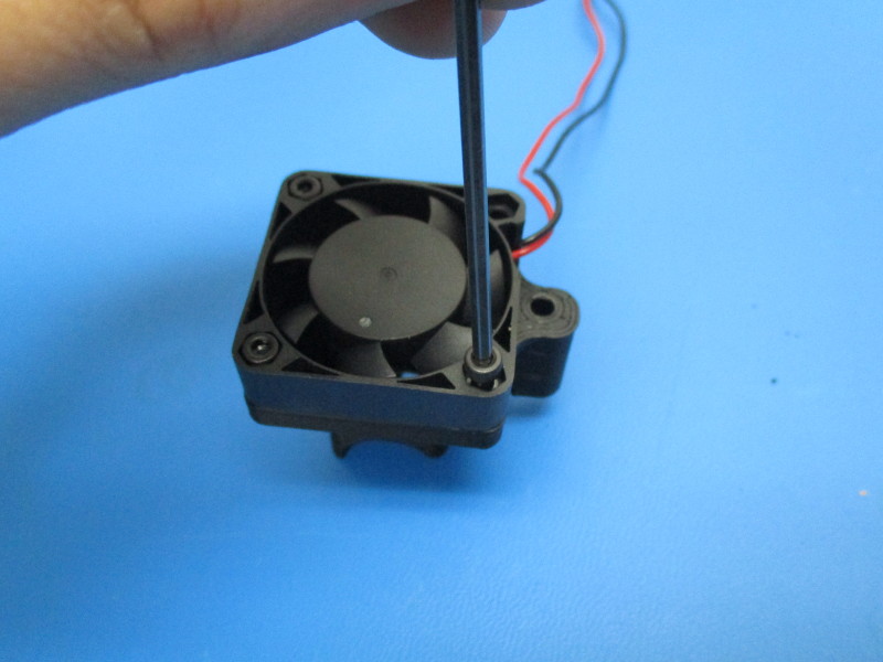
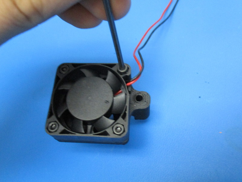
Attach using M3x12 SHCS on the lower two screw mount holes on the fan (see image “Mounting 24v fan screw 1” and “Mounting 24v fan screw 2”) Torque to 3in*lbs
Gather parts
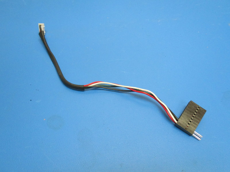
-Motor switch harness
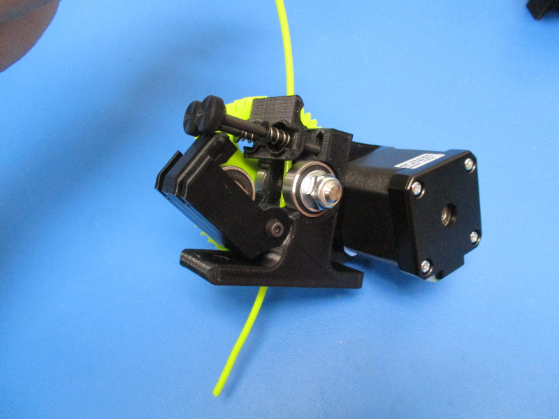
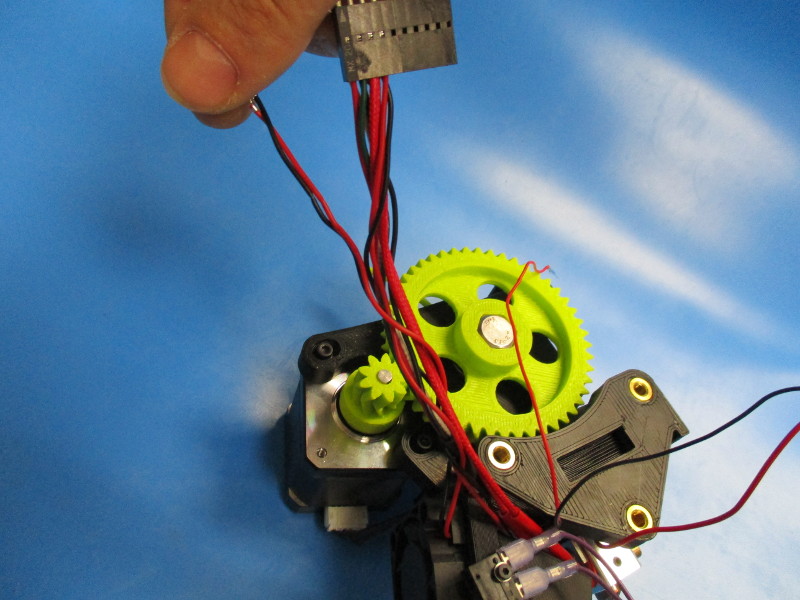
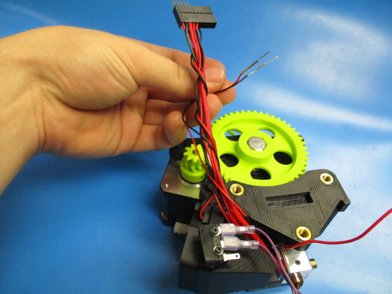
Lay the extruder so that it is resting flat on the large herringbone gear.
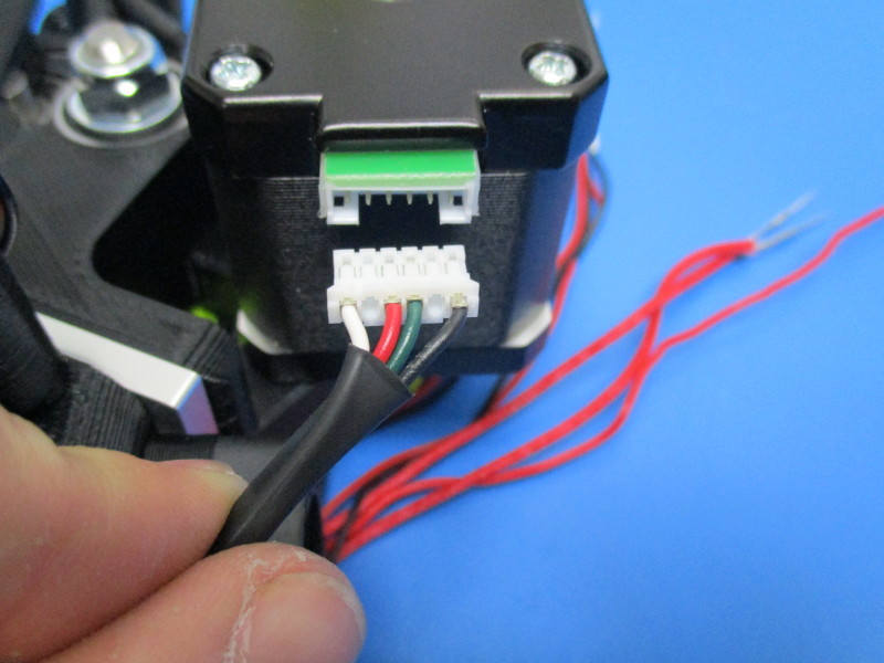
Insert the white JST connector side of the motor switch harness into the connector on the motor. ( see image “Harness insertion orientation”)
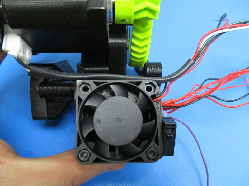
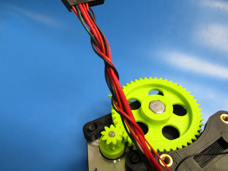
Run the harness on top of the 24v fan ( see image” Motor harness placement”)
Flip the extruder over so that the large herringbone gear is facing up.
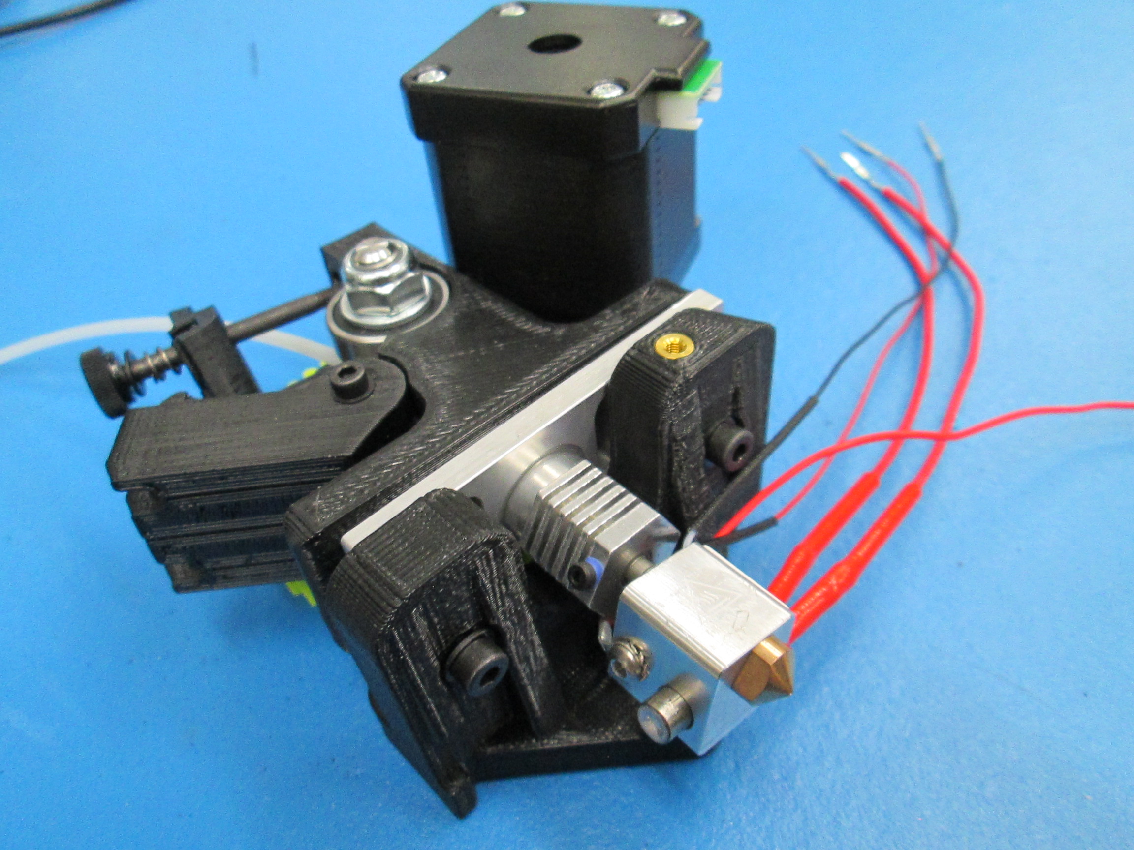
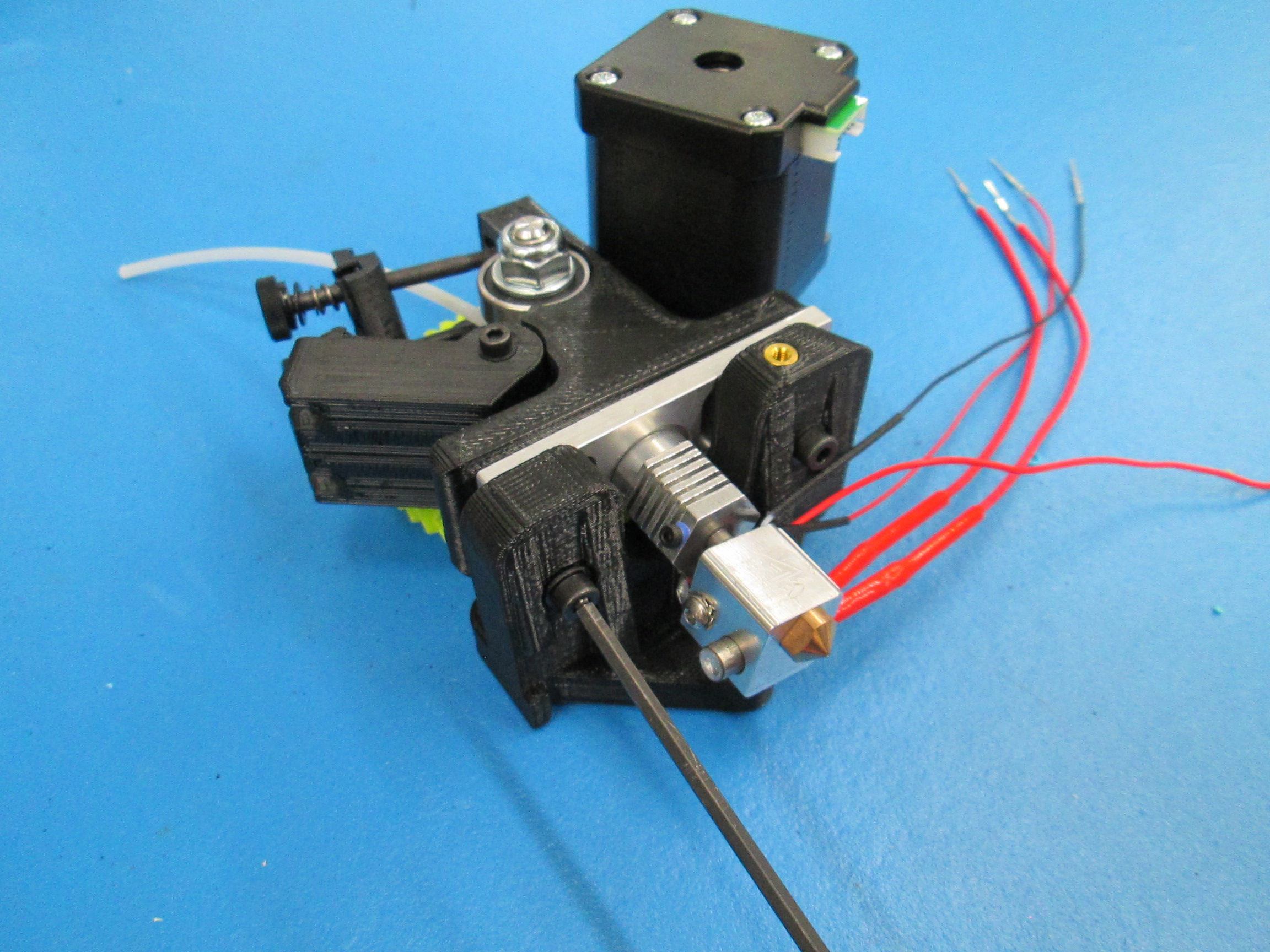
Most of the harnesses going to the 20 pin connector will need to twist around the motor switch harness.
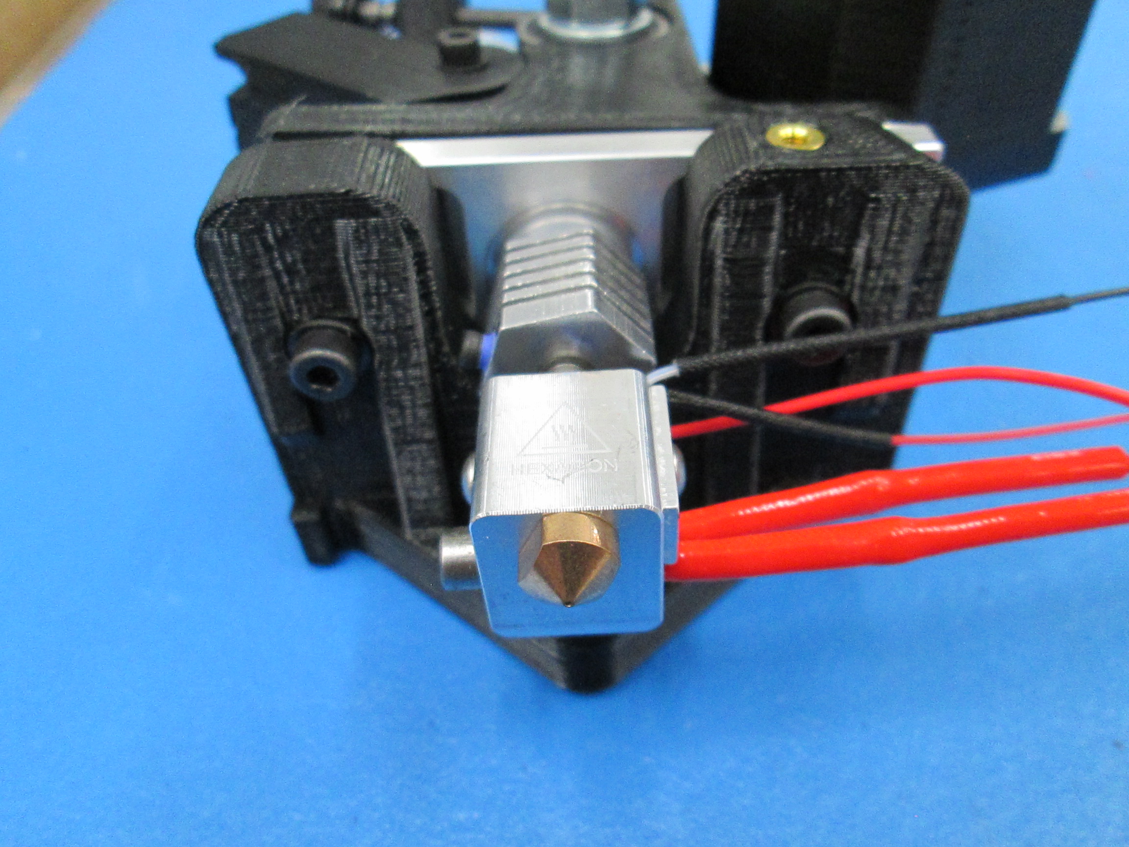
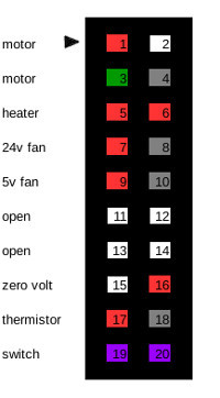
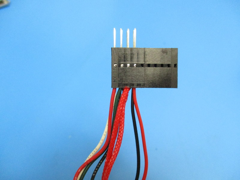
Start with connecting the heater cartridge harness. The heater cartridge harness will sit parallel with the motor switch harness, no twisting required (see image “ Heater cartridge connected”) Plug the heater cartridge pins into pin position 5 and pin position 6 (see image “Pin placement”)
Connecting the 24v fan harness This harness will also run parallel with the motor switch harness (see image “24v fan connected”) Connect the 24v fan harness red wire in pin position 7 and the black wire in pin position 8 (see image “Pin placement”)
Connecting the 5v fan harness This harness needs to be twisted around the motor switch harness, heater cartridge and 24v fan harness 3 times to reduce the length of the harness. (see image “twisting 5v harness” and “connected 5v fan) Connect 5v fan harness red wire in pin position 9 and black wire in pin position 10 (see image “Pin placement”)
Connecting the thermistor harness This harness needs to be twisted 1 time around the previously connected harness. ( see image “twisting thermistor”) Connect the thermistor harness red wire in pin position 17 and black wire in pin position 18 (see image “Pin placement”)
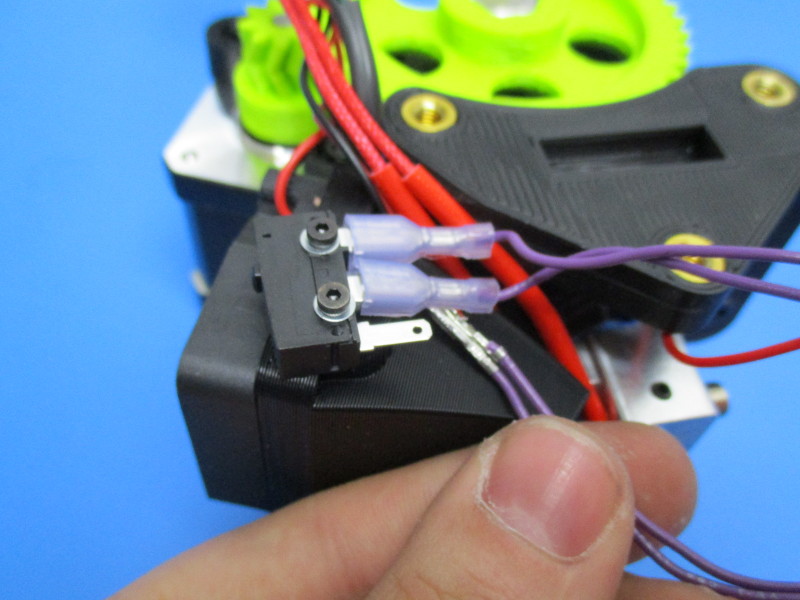
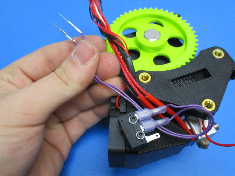
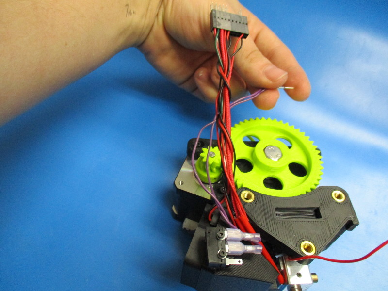
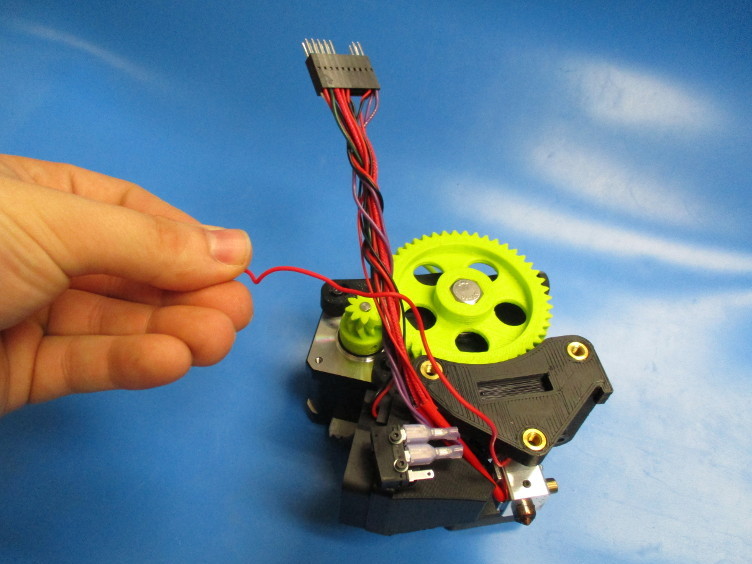
Connect the switch harness. Take the pin side of the harness and run it under the switch (see image “Feeding switch harness” and “switch harness loop”) Pull the harness until the loop closes (see image ”closing loop”) Connect the switch harness into connector position 19 and 20 (see image “Pin placement”)
Connecting the zero volt sense This harness needs to be twisted around the installed wire 4 times. ( see image “twisting zero volt harness”) Connect the zero volt harness into pin position 16 (see image “Pin placement”)
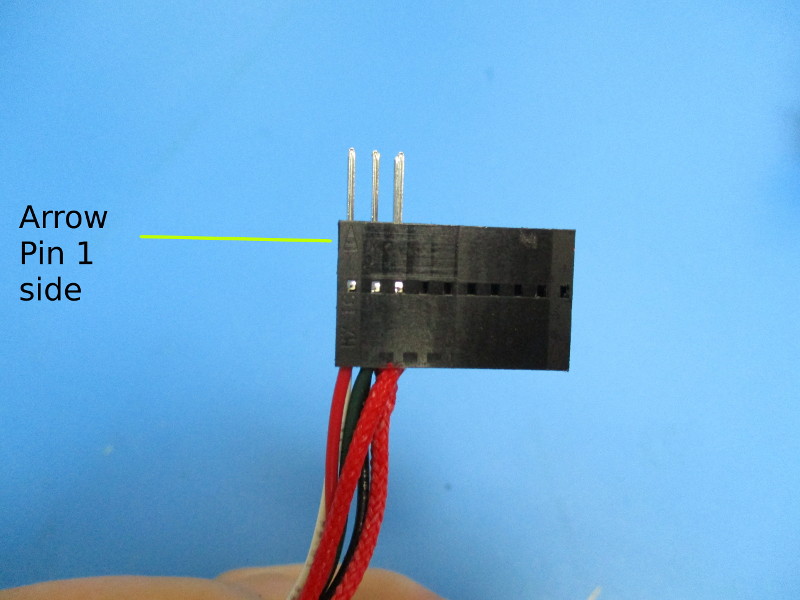
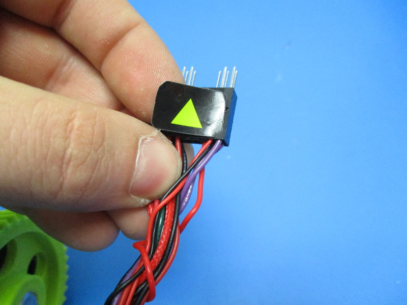
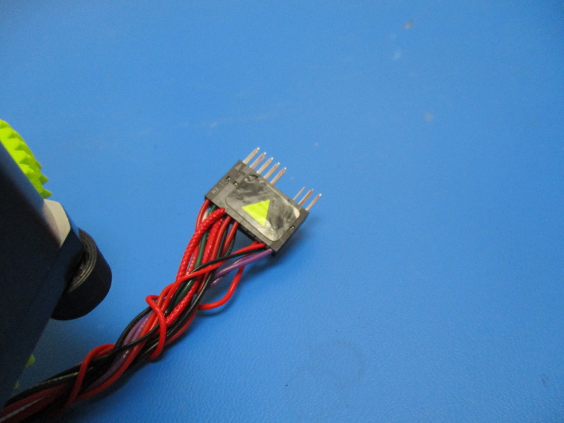
Gather supplies
Apply direction arrow sticker to the pin 1 side of the 20 pin connector