Open HardwareAssembly Instructions
Guides for installation and assembly of the LulzBot line of products made by FAME 3D LLC.
Guides for installation and assembly of the LulzBot line of products made by FAME 3D LLC.
Materials Needed:
1x- USB support (PP-GP0247)
1x-Mini RAMBo 1.3a (PC-AS0032)
4x- Stainless Steel M3x8mm Button Head Cap Screws (HD-BT0104)
2x- Cable Tie Downs (HD-MS0249)
1x- Heat SInk
Tools Needed:
2mm Hex Driver
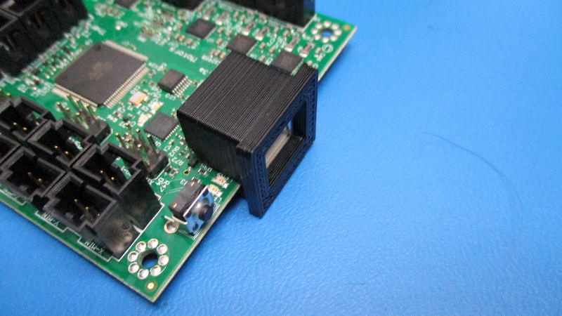
Attach the USB support (PP-GP0247) to the the Mini RAMBo 1.3a (PC-AS0032). Slide the USB support onto the USB housing on the Mini RAMBo as pictured.
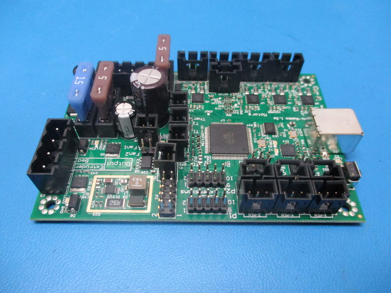
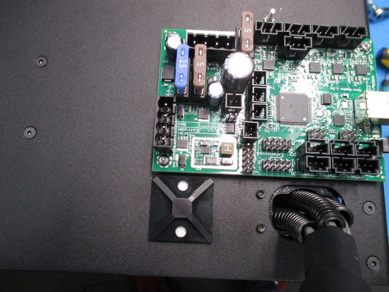
Mount the RAMBo to the Mini left plate. Fasten the RAMBo to the 4 standoffs on the left plate using 4 Stainless Steel M3x8mm Button Head Cap Screws (HD-BT0104). Orient the Rambo such that the USB port faces toward the right side (see pictures). Torque to 5 in*lbs.
Now we will install 2 Cable Tie Downs (HD-MS0249 ) onto the Mini left plate.
Install one cable tie down onto the Mini left plate just below the upper strain relief and centered along the left edge of the strain relief as pictured.
Install the second tie down just under the bottom left RAMBo mounting standoff oriented along the bottom edge of the RAMBo. The tie down should be flush with the left edge of the RAMBo as pictured.


Materials Needed:
2x- 8 inch zip ties (HD-MS0058)
Tools Needed:
Flush Cutters
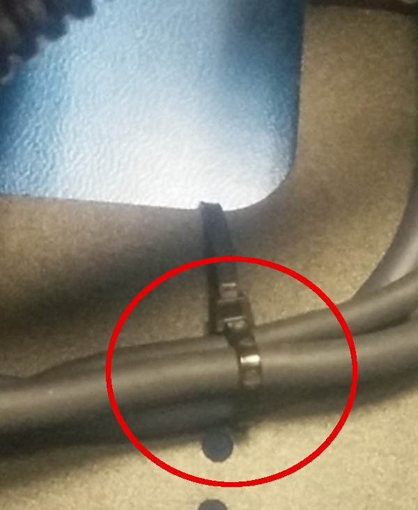
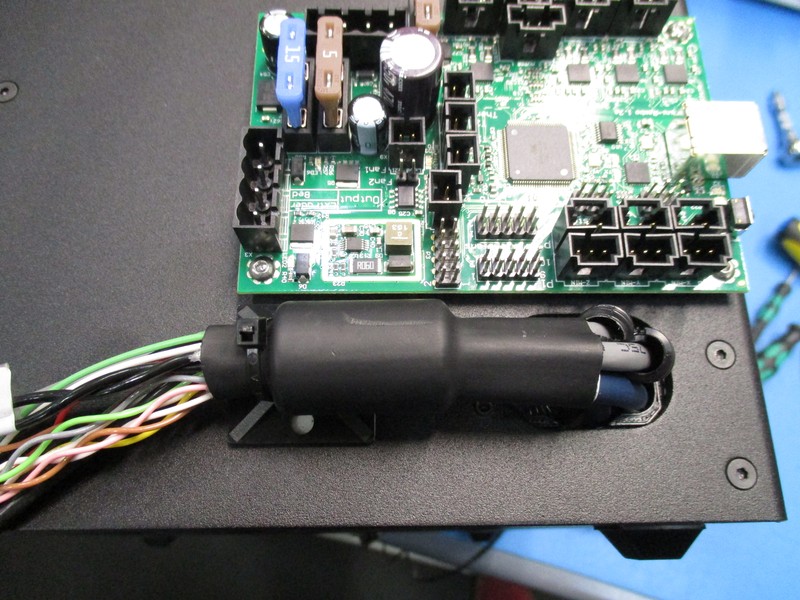
Insert the Molex terminated end of the Extruder Cable Harness (EL-HR0108) through the upper strain relief. Use an 8 inch zip tie (HD-MS0058) to fasten the ferrite to the cable tie down as pictured.
Insert the Molex terminated end of the Bed Cable Harness (EL-HR0114) through the lower strain relief. Use an 8 inch zip tie to fasten the cable to the cable tie down as pictured.

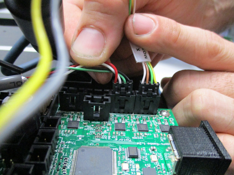
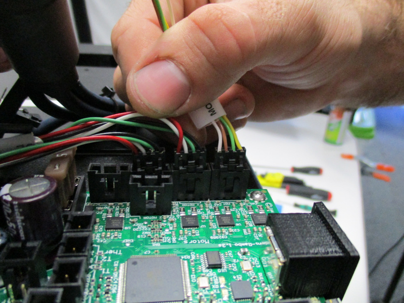
Plug in motors into the RAMBo electronics board.
First locate the 4 pin Molex connector labeled “X Motor” and plug it into the board as pictured.
Locate the 4 pin Molex connector labeled “Y Motor” and plug it into the board as pictured.
Locate the two 4 pin Molex connectors labeled “Z Motor” and plug them into the board as pictured.
Locate the 4 pin Molex connector labeled “E Motor” and plug it into the board as pictured.
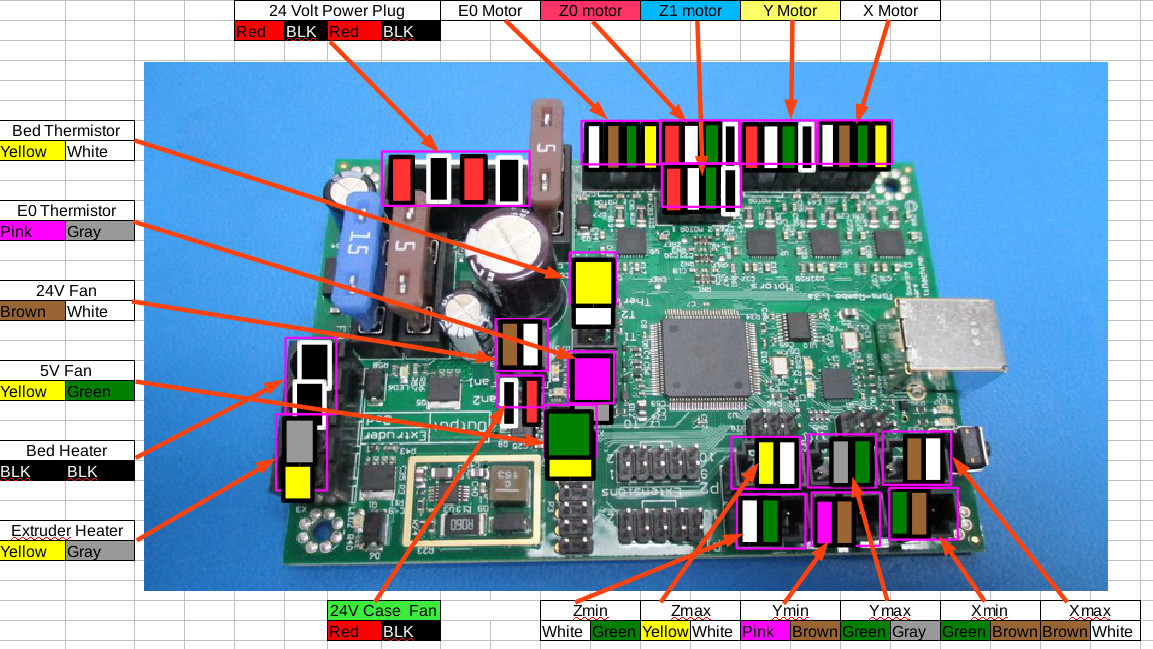


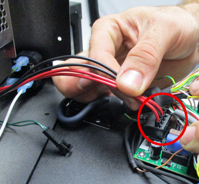
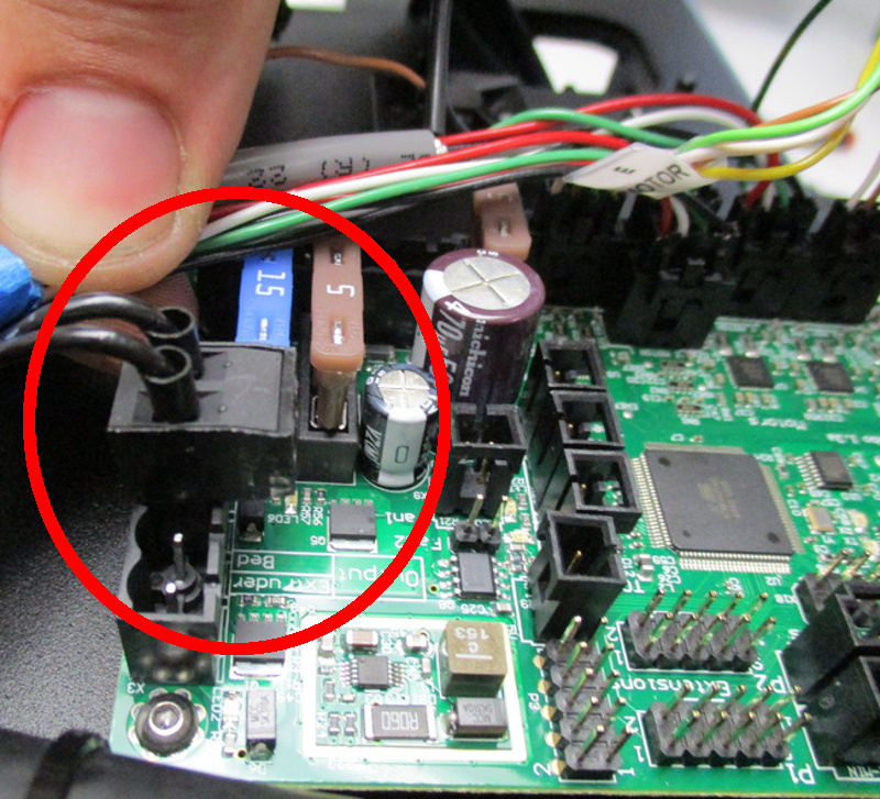
Plug in the two heater cables.
Locate the 2 pin terminal block plug labeled “Bed Heater” and plug in as pictured
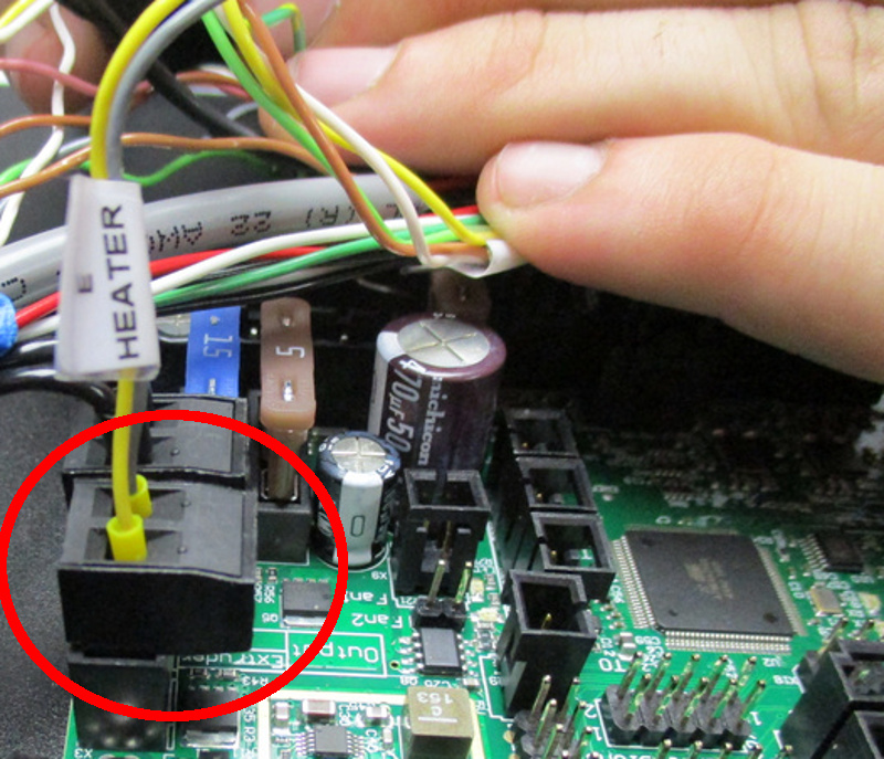
Locate the 2 pin terminal block plug labeled “E Heater” and plug in as pictured.

Materials Needed:
1x- 8 inch Cable Tie (HD-MS0058)
Tools Needed:
Flush Cutters
Instructions:
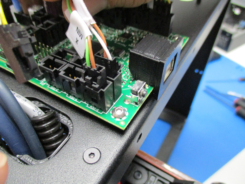
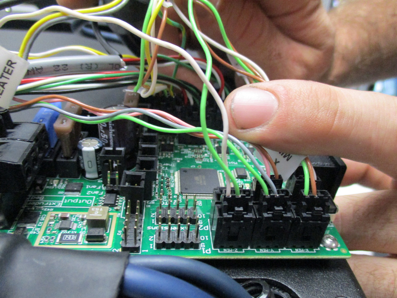
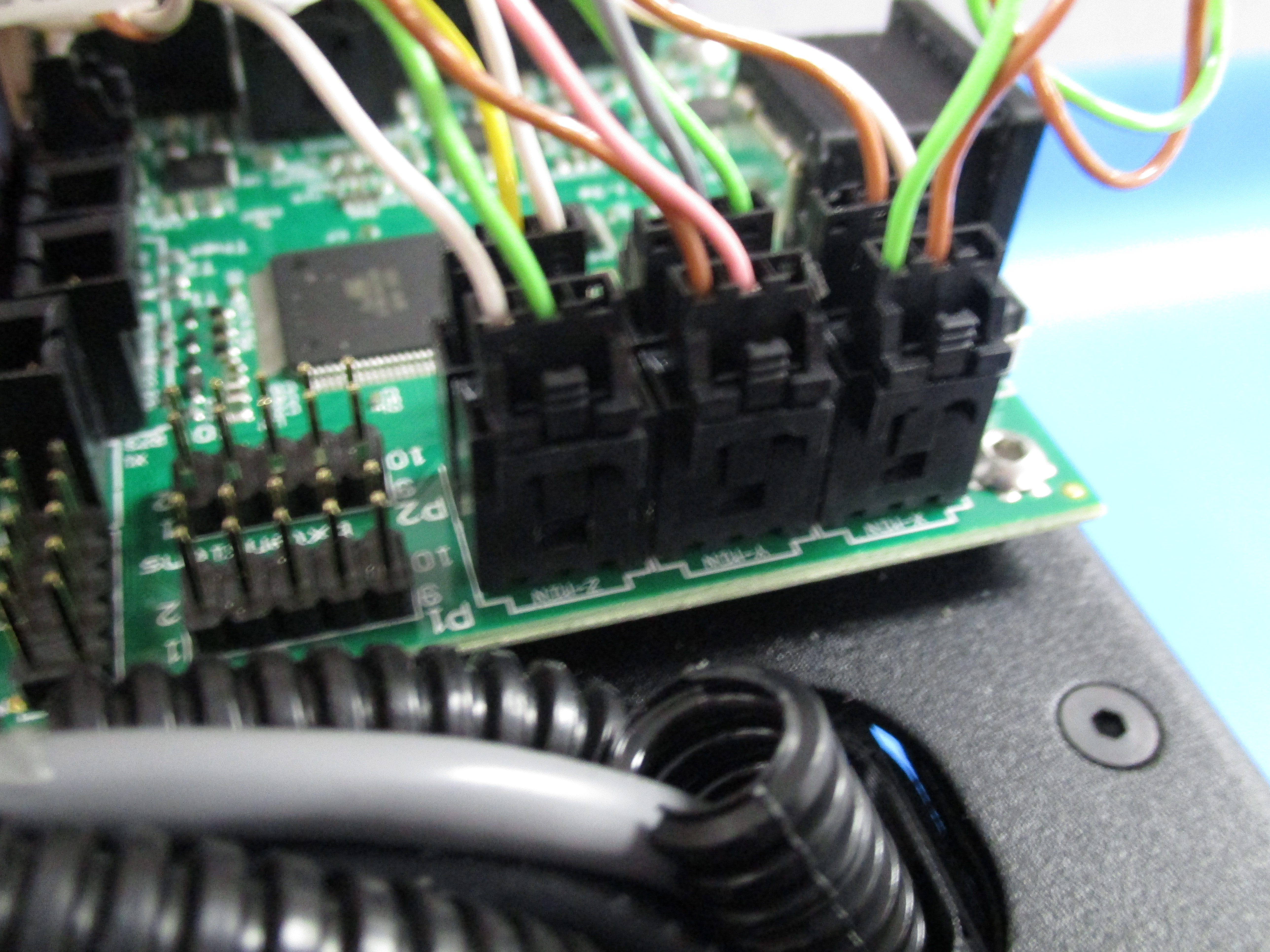
Locate the three pin Molex connector labeled “X min” and plug it into the RAMBo as pictured.
NOTE: The two (very long) X_Min wires are folded on themselves three times and ziptied together and NOT to other wires.
Locate the three pin Molex connector labeled “X max” and plug it into the RAMBo as pictured.
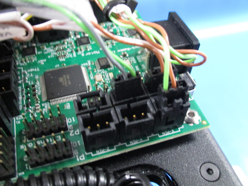
Locate the three pin Molex connector labeled “Y min” and plug it into the RAMBo as pictured.
Locate the three pin Molex connector labeled “Y max” and plug it into the RAMBo as pictured.
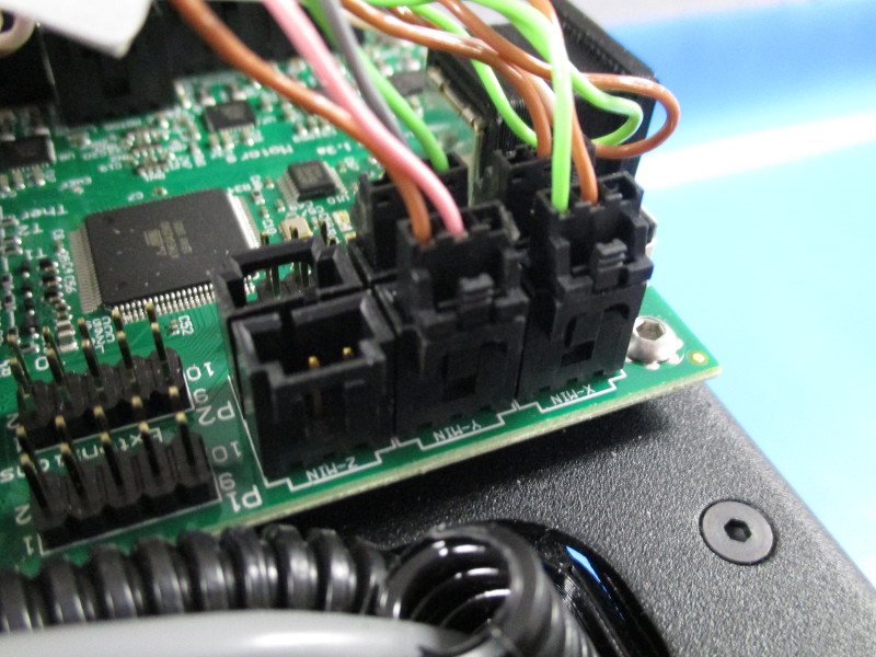
Locate the three pin Molex connector labeled “Z min” and plug it into the RAMBo as pictured.
Locate the three pin Molex connector labeled “Z max” and plug it into the RAMBo as pictured.


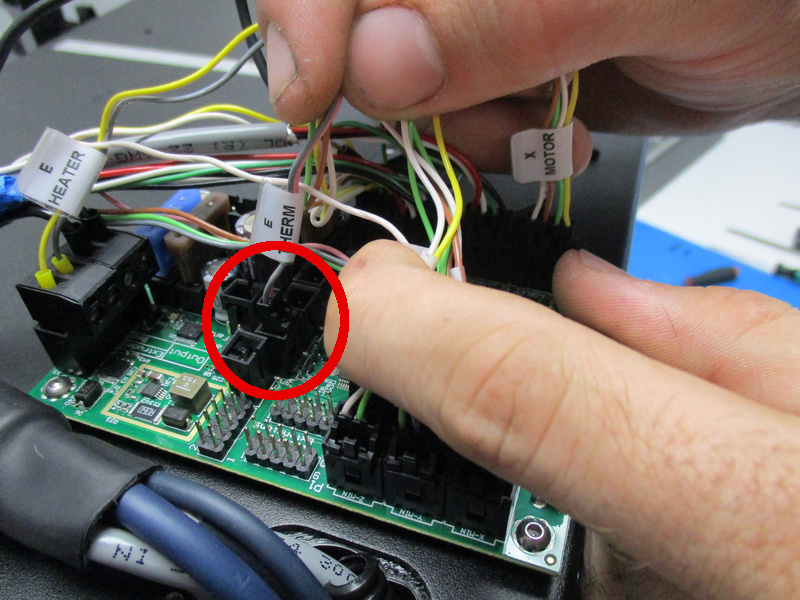
Locate the two pin Molex connector labeled “E Therm” and plug in as pictured.
Locate the two pin Molex connector labeled “Bed Therm” and plug in as pictured.


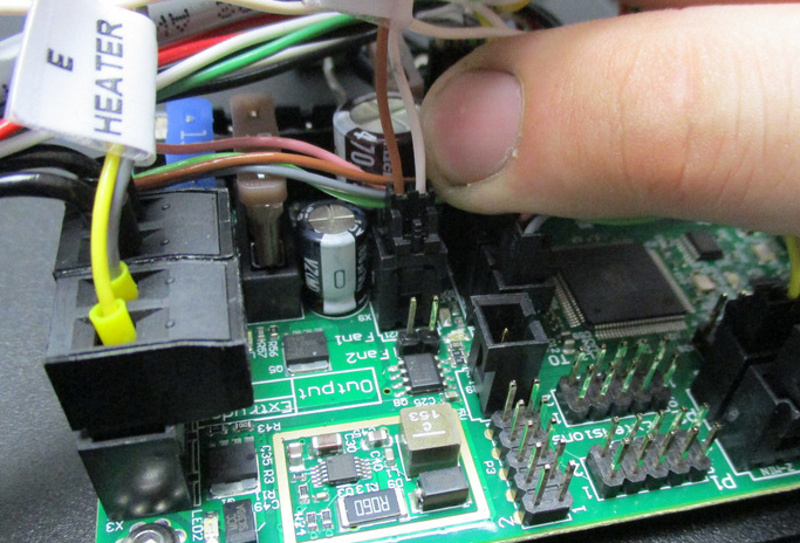
Locate the two pin Molex connector labeled “24V Fan” and plug in as pictured.
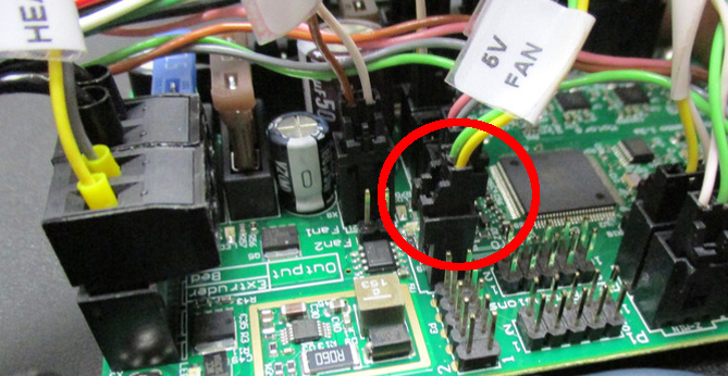
Locate the two pin Molex connector labeled “5V Fan” and plug in as pictured.

Materials Needed:
1x- M3 lock washer (HD-WA0035)
1x- M3 lock nut (HD-NT0001)
1x- Chassis Ground Extension Cable (EL-HR0118)
Tools Needed:
5.5mm nut driver
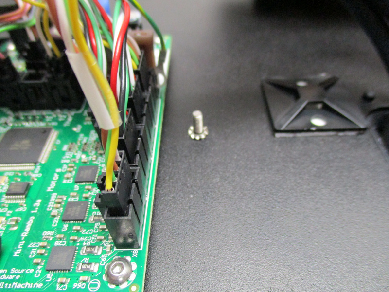
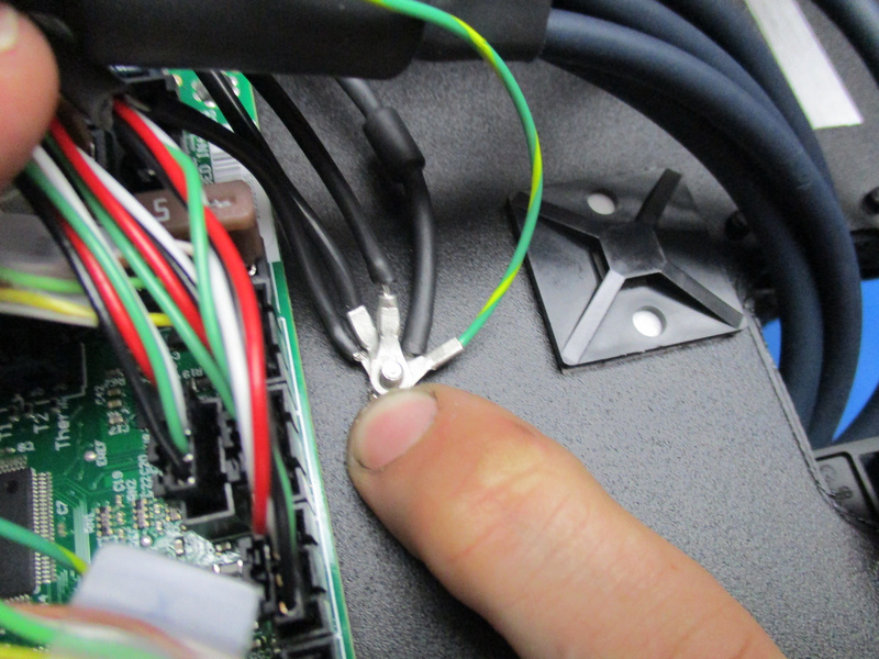
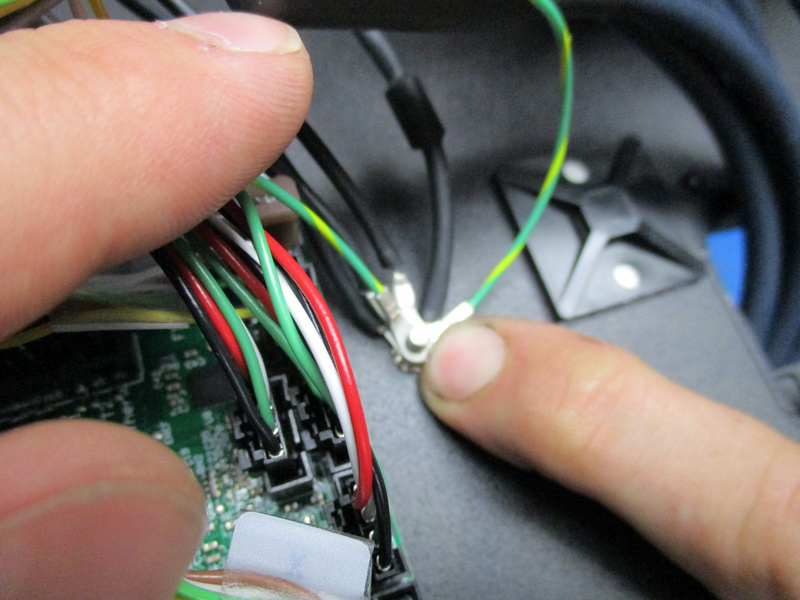
First put an M3 lock washer (HD-WA0035) onto the ground post on the Mini left plate.
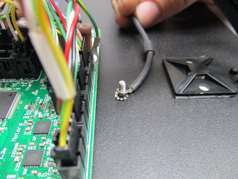
Next install the ring terminal of the TVS Diode wire onto the ground post.
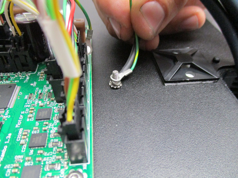
Install the ring terminal of the X motor ground wire onto the ground post.
Install the ring terminal of the Y motor ground wire onto the ground post.
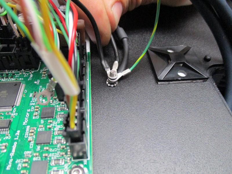
Install the 2 ring terminals of the Z motors ground wires onto the ground post.
Install the ring terminal of the Extruder motor ground wire onto the ground post.
Install the 2 ring terminals of the Chassis Ground Extension (EL-HR0118) cable onto the ground post.
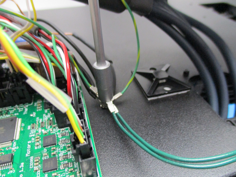
Use a 5.5mm nut driver and an M3 lock nut to fasten all of these wires onto the ground post. Tighten nut until the ring terminals can no longer move.


Materials Needed:
1x- 8in cable tie (HD-MS0058)
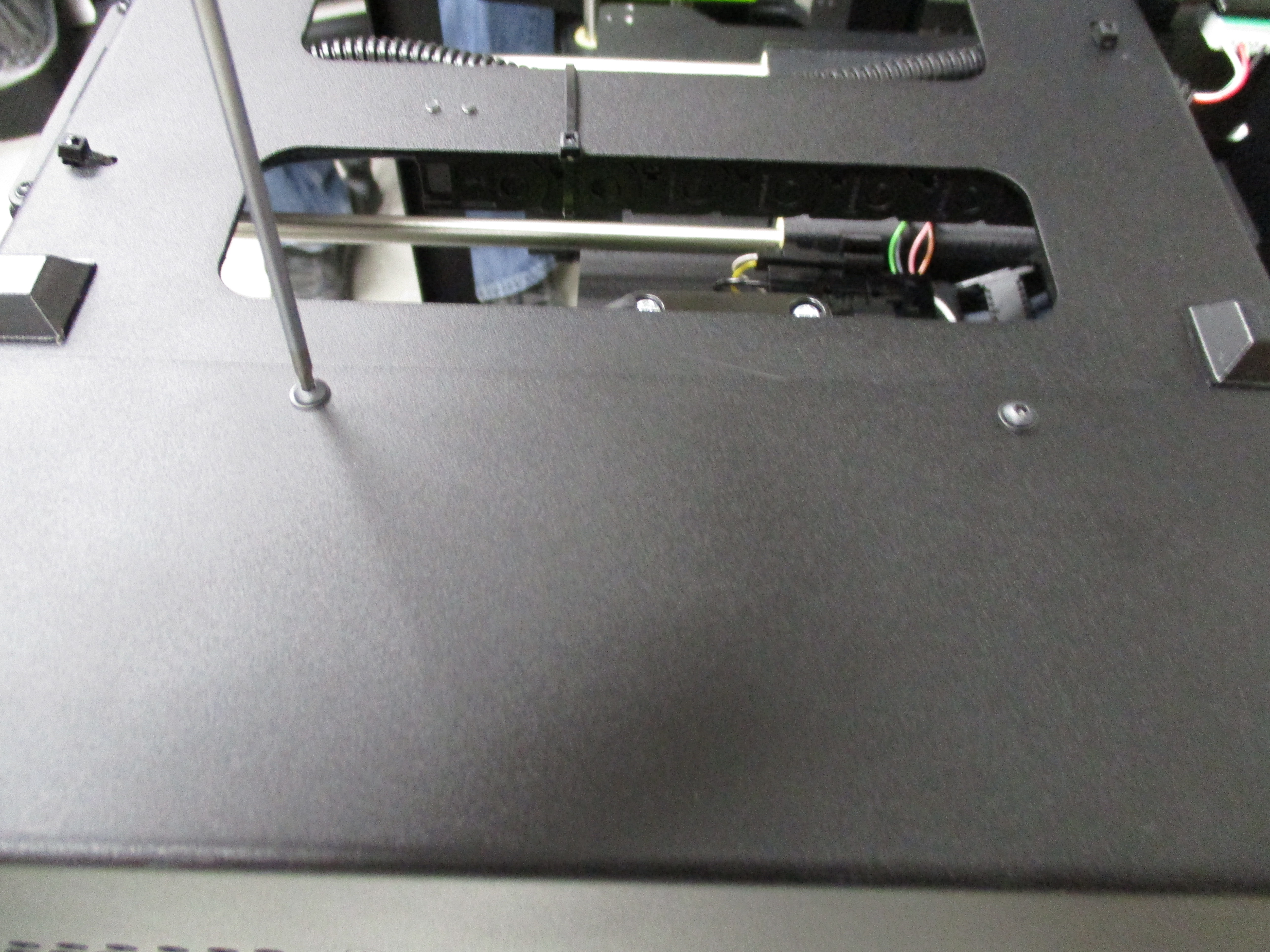
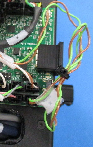
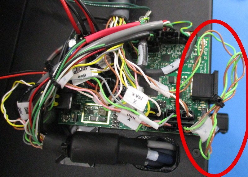
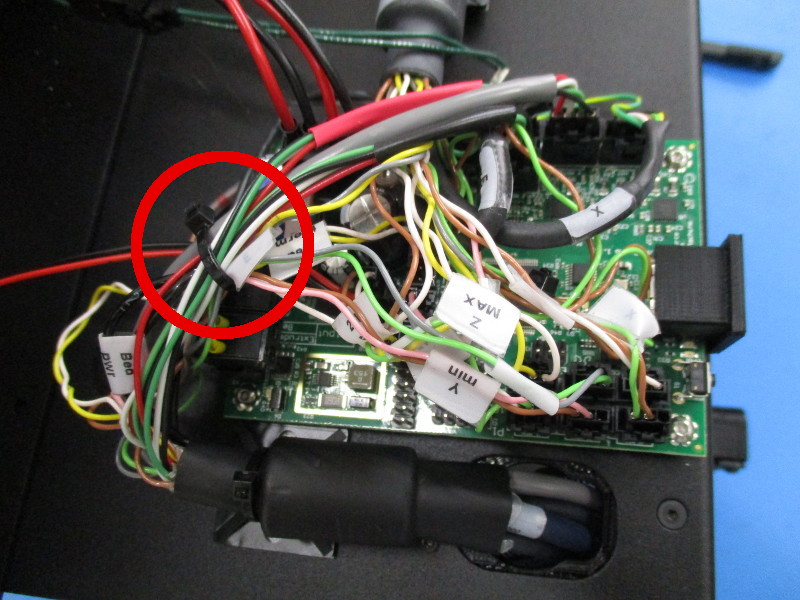
Locate the X-Min wire bundle that was previously pushed aside;
Place the excess X-Min bundle under the stack of wires that pass over the top of the rambo.
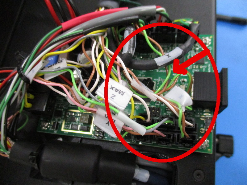
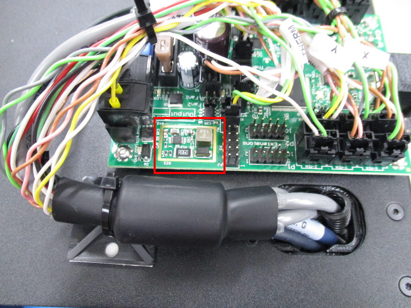
Route cables coming from the YZ harness away from the regulator (red square in picture) and include the Extruder heater in the cable tie.
Exclude the bed heater, the diode and both Z grounds from the cable tie.
Secure the cable tie around the listed wires approximately where shown to keep wires from gathering above the gold rectangle/ voltage regulator area.

Materials Needed:
6x- M3x6mm Black Oxide Flat Head Cap Screws (HD-BT0128)
2x- M3x 8mm Black Oxide BHCS
2x- M3 Washer Black Oxide
4x- 8" Cable tie (HD-MS0058)
Tools Needed:
2mm hex driver
Attach the 24V terminal block to the RAMBo as pictured.
Attach the Chassis to Ground Extension cable to the Earth Ground Extension cable. Click the 2 pin Molex connectors together. See picture.
Attach the Case fan wires (Red and Black wires with a two position connector) to the RAMBo FAN2 header
Attach the Electronics Case to the Mini left plate. Use 6 M3x6mm Black Oxide Flat Head Cap screws to fasten the case to the left plate front and left plate back. Torque to 5 in*lbs.
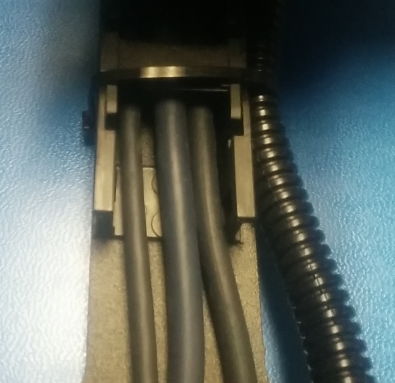
Ensure cables inside the cable chain are not overlapping or twisted
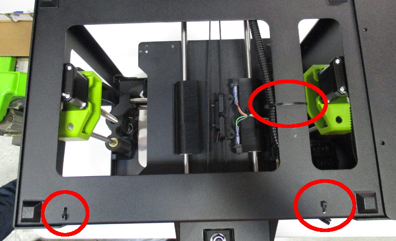
Gather the Y axis cable harness (three blue cables inside the cable chain) and route them near the cable tie down location at the front of the frame
Secure only the Y axis cable harness with a cable tie, the cable tie should be located near the case tie down holes
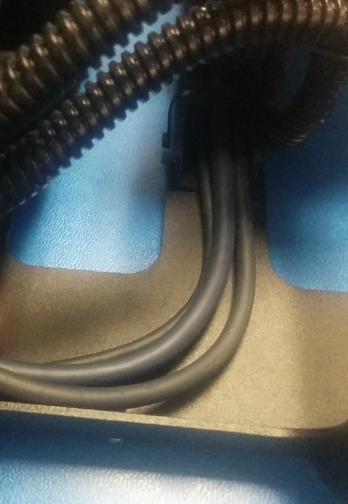
Ensure sufficient slack at the motor connections is given to prevent damage and accidental unplugging.
With a cable tie secure the bundled Y axis harness and , tighten the cable tie to prevent cables from moving
Secure the Z Axis right motor harness, Y axis motor harness, and the Y axis cable harness to the bottom plate with cable ties in the noted locations.
Secure bottom of case to frame with 2x- M3x 8mm Black Oxide BHCS and washers black oxide, Torque to 5 in*lbs.