Open HardwareAssembly Instructions
Guides for installation and assembly of the LulzBot line of products made by FAME 3D LLC.
Guides for installation and assembly of the LulzBot line of products made by FAME 3D LLC.
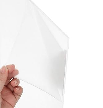
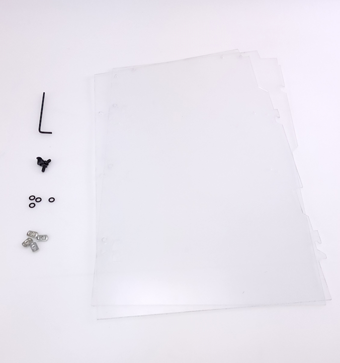
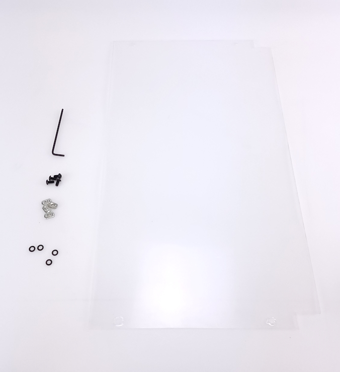
Each of the clear panels will have a protective cover on both sides of the acrylic.
This cover should be removed prior to assembly.
For ease of pictures, it has been left on for these instructions for better visualization.
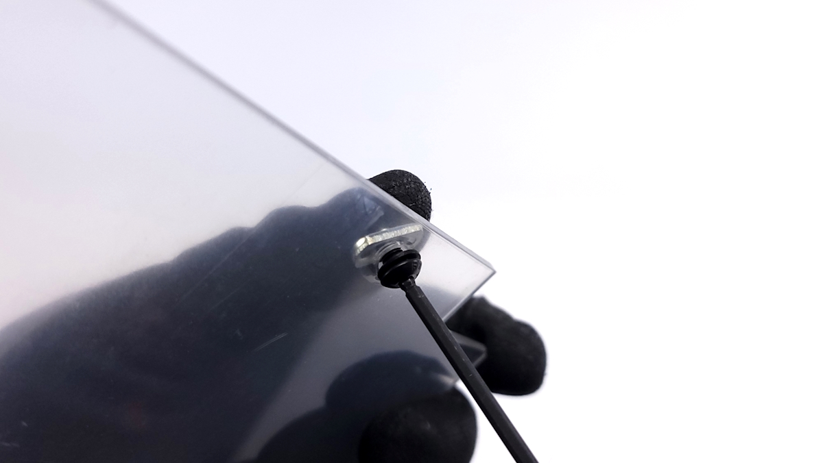
WARNING: Do not overtighten screws that go through the acrylic!
Overtightening screws will result in the panels cracking.
Damage due to overtightening is not covered under warranty.
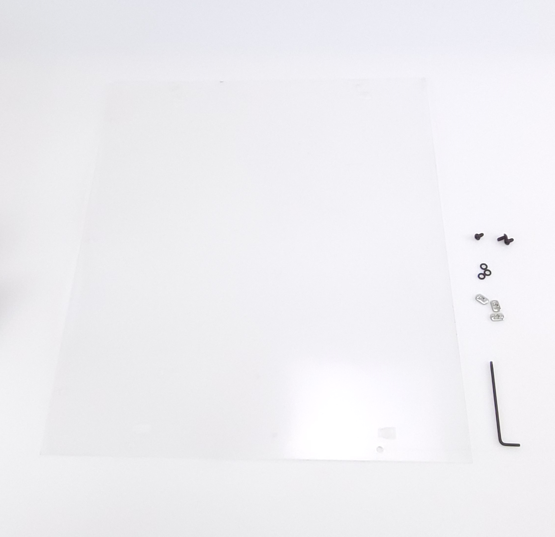
-2.5mm hex wrench
-3mm hex wrench
-4mm hex wrench
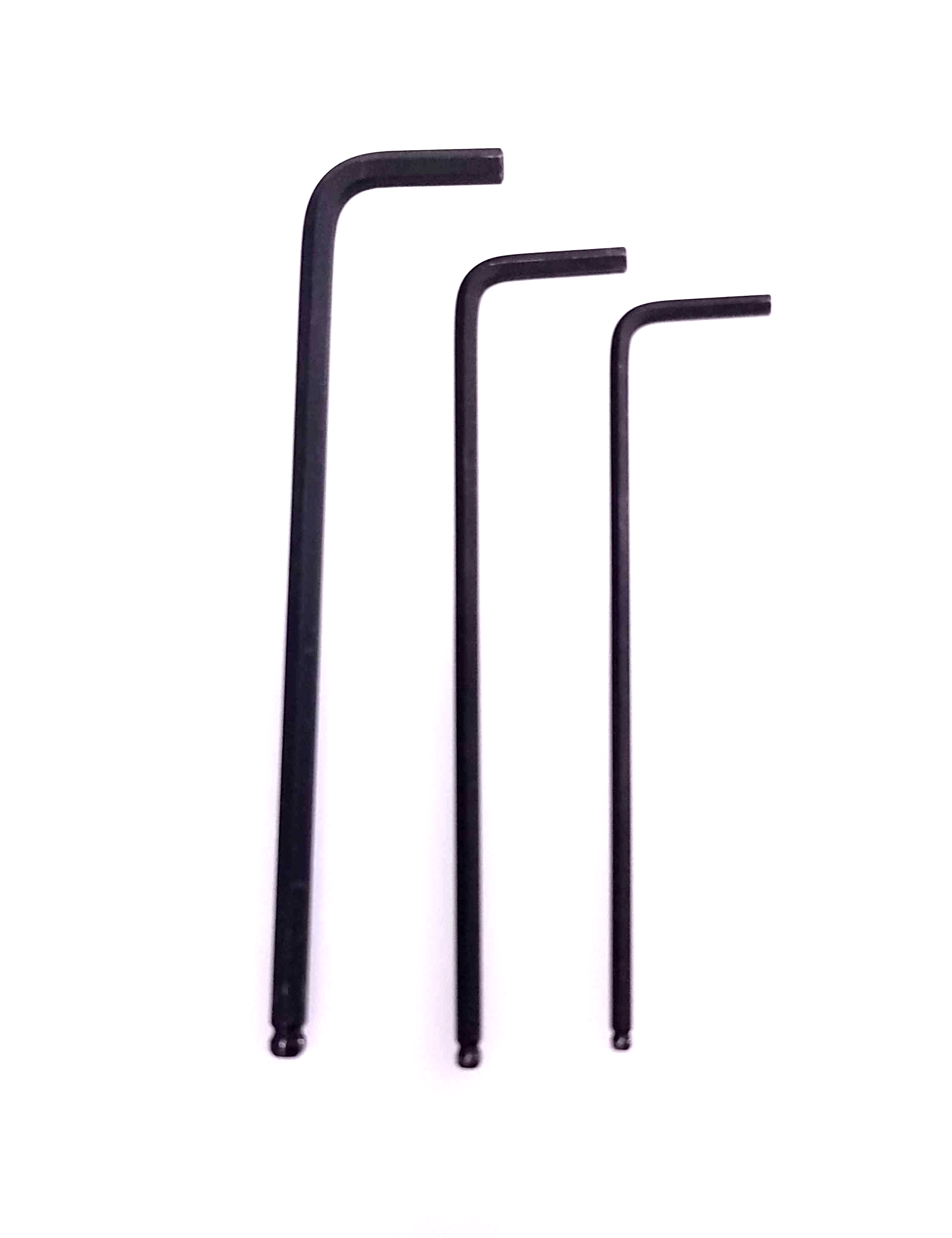
Items required:
- 4x - M5 x 10mm BHCS
- 4x - M5 x 14mm SHCS
- 8x - M5 washers
- 4x - M5 Slide in T-nuts
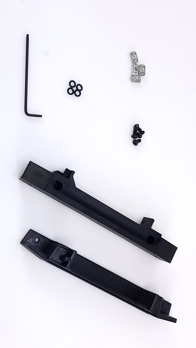
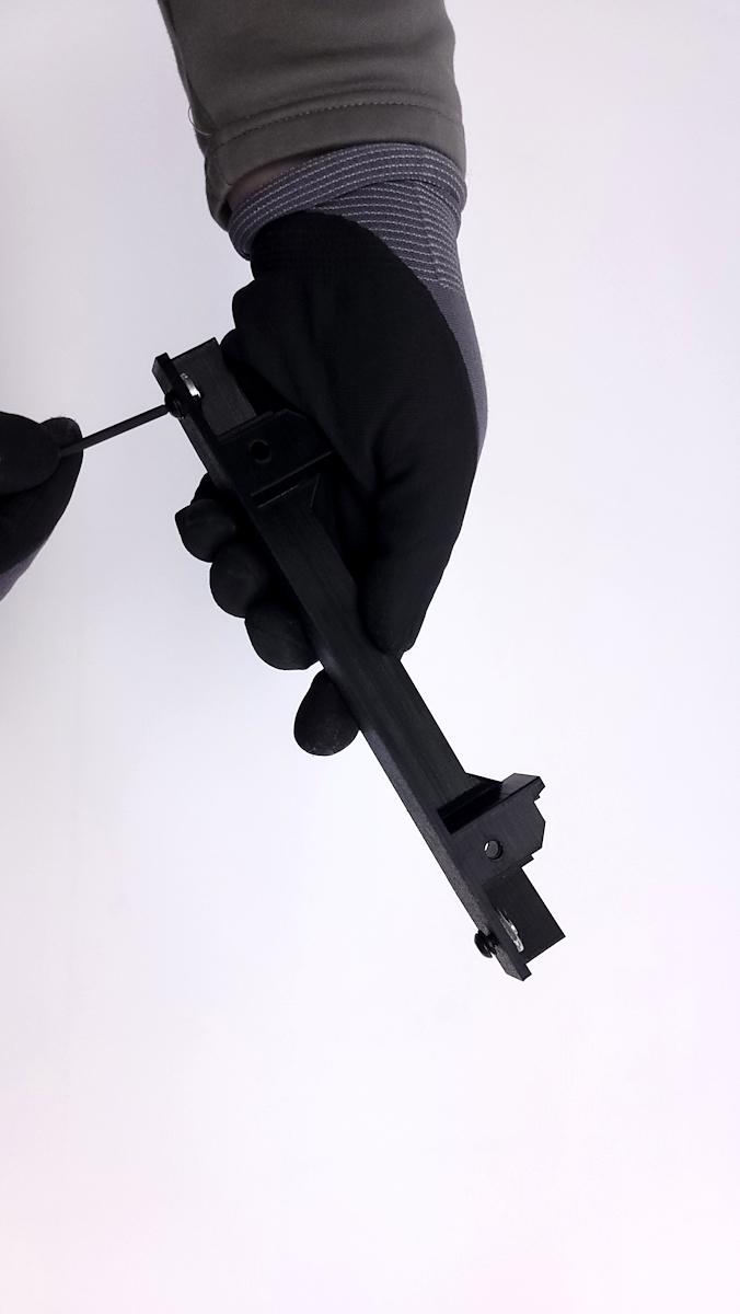
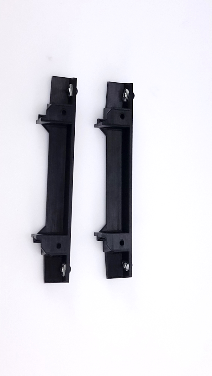
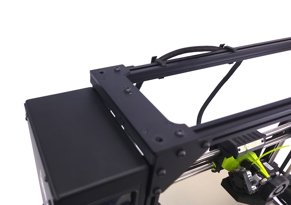
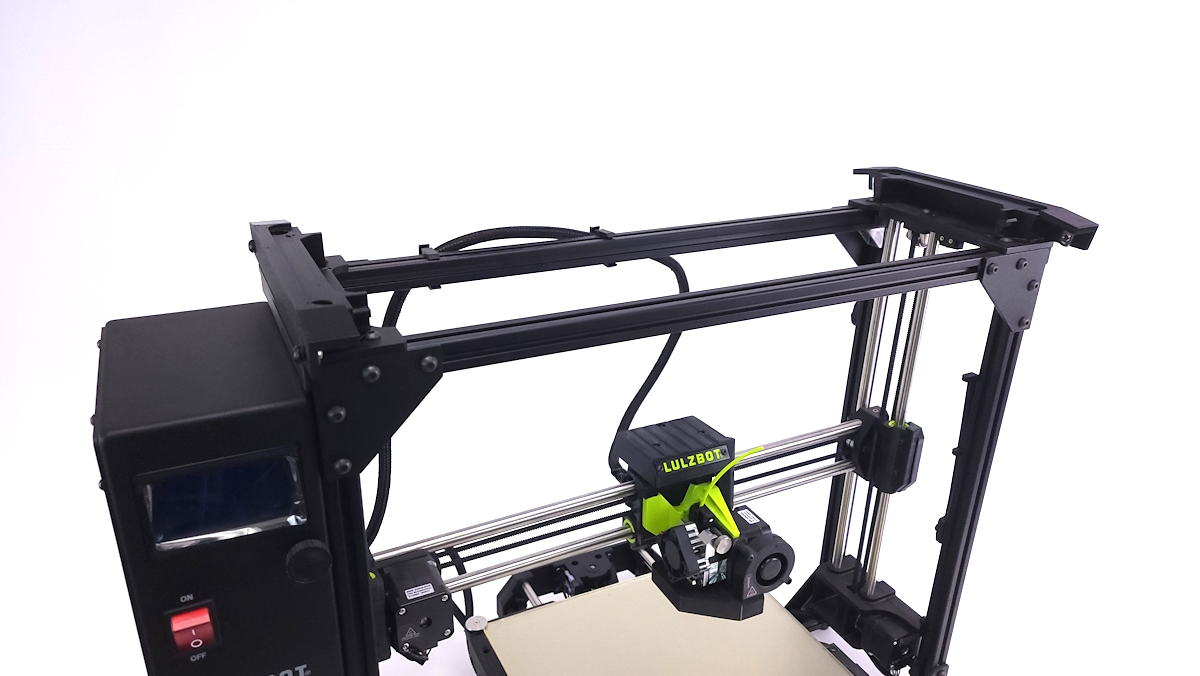
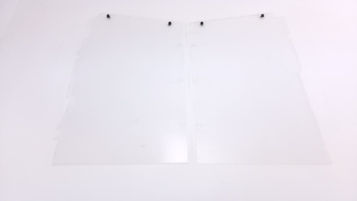
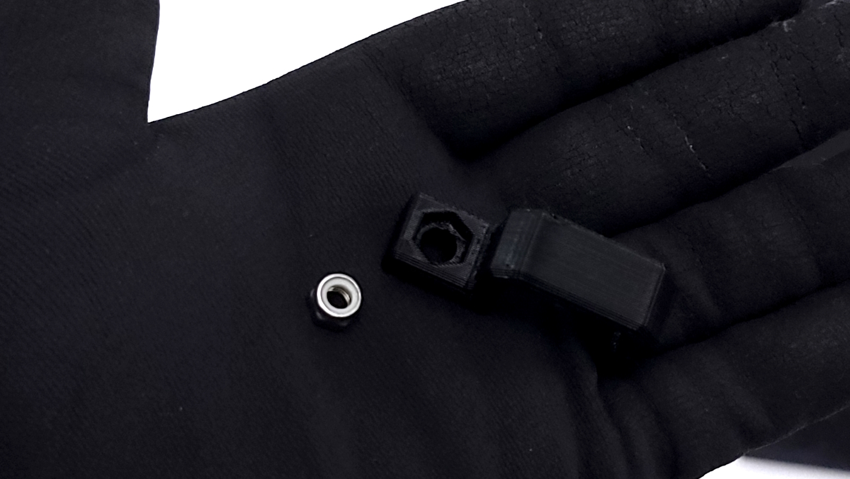
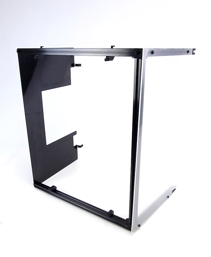
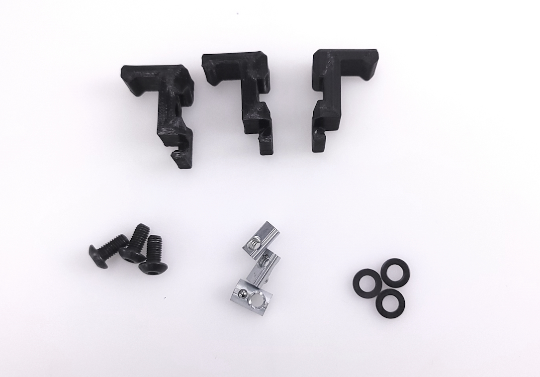
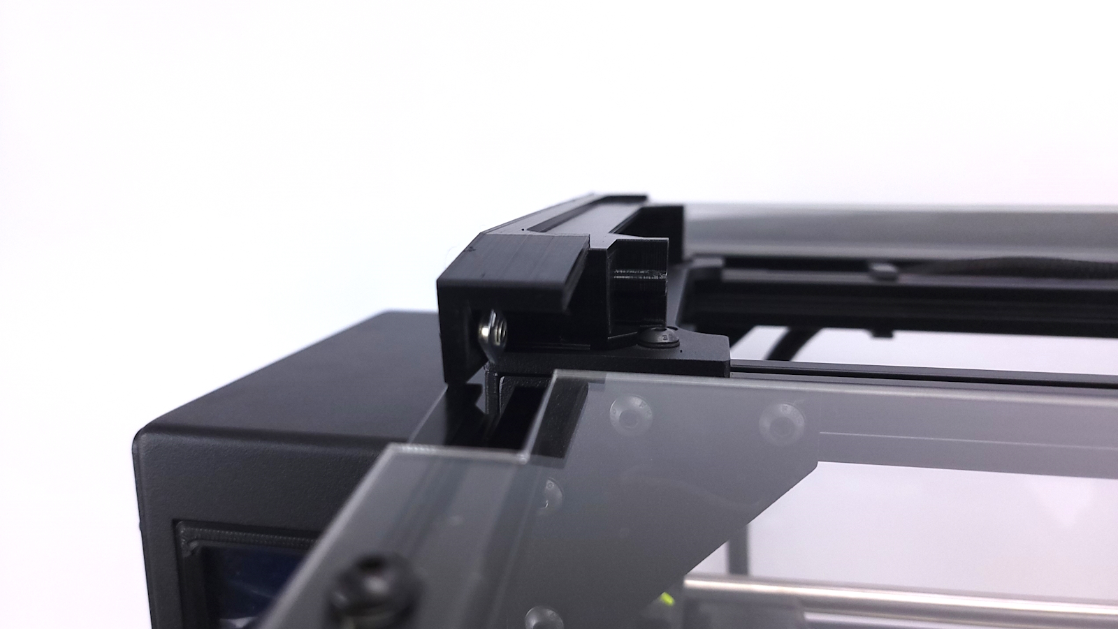
Locate the 2 upper 3D printed brackets.
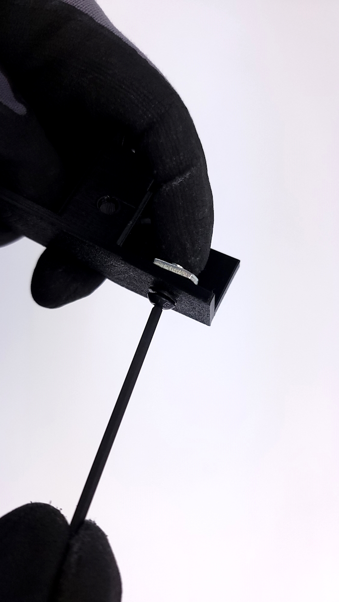
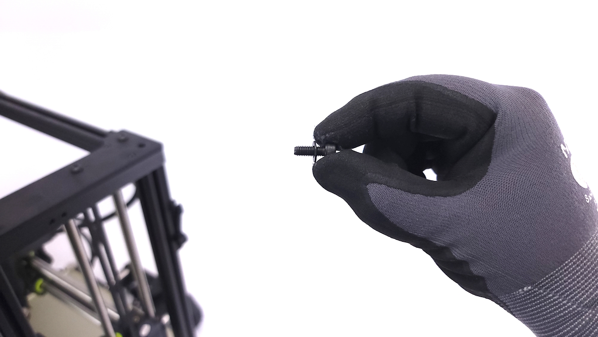
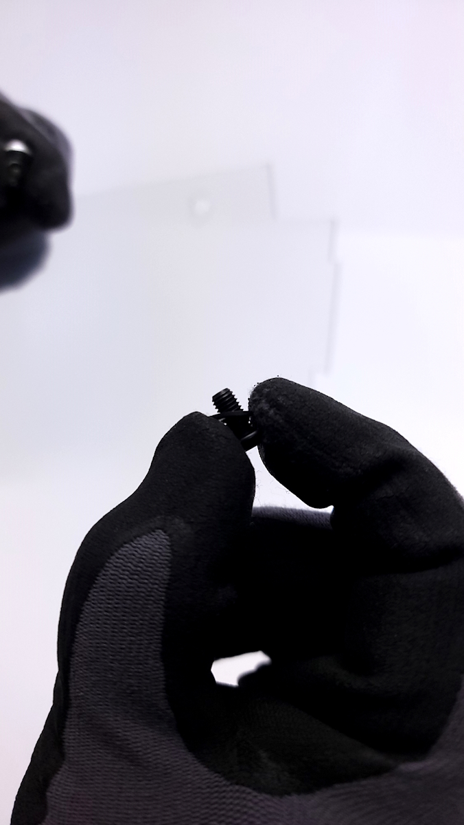
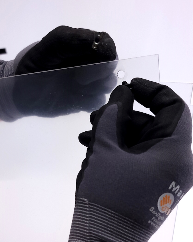
Using the 4 smaller button head cap screws, washers, and slide in t-nuts, start each corner of the bracket.
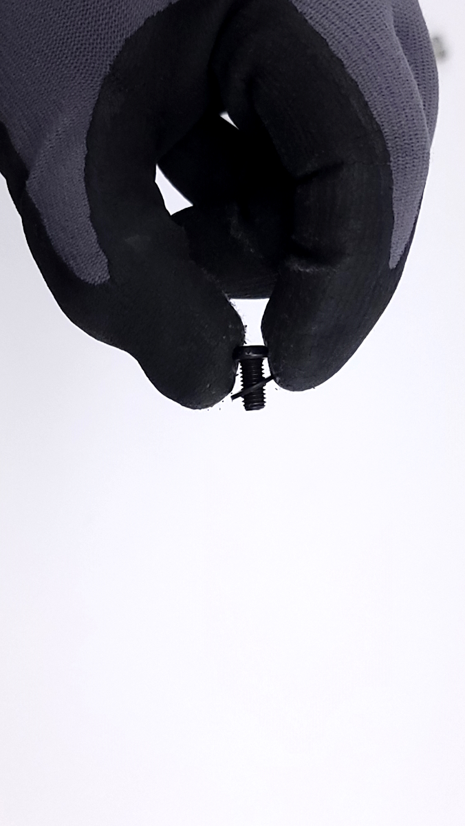
When installing the t-buts, be sure that you are orienting them with the flat surface in towards the top of the screw. If the t-nuts are installed with the flat side facing away from the head of the screw, they will not slide into the extrusion correctly.
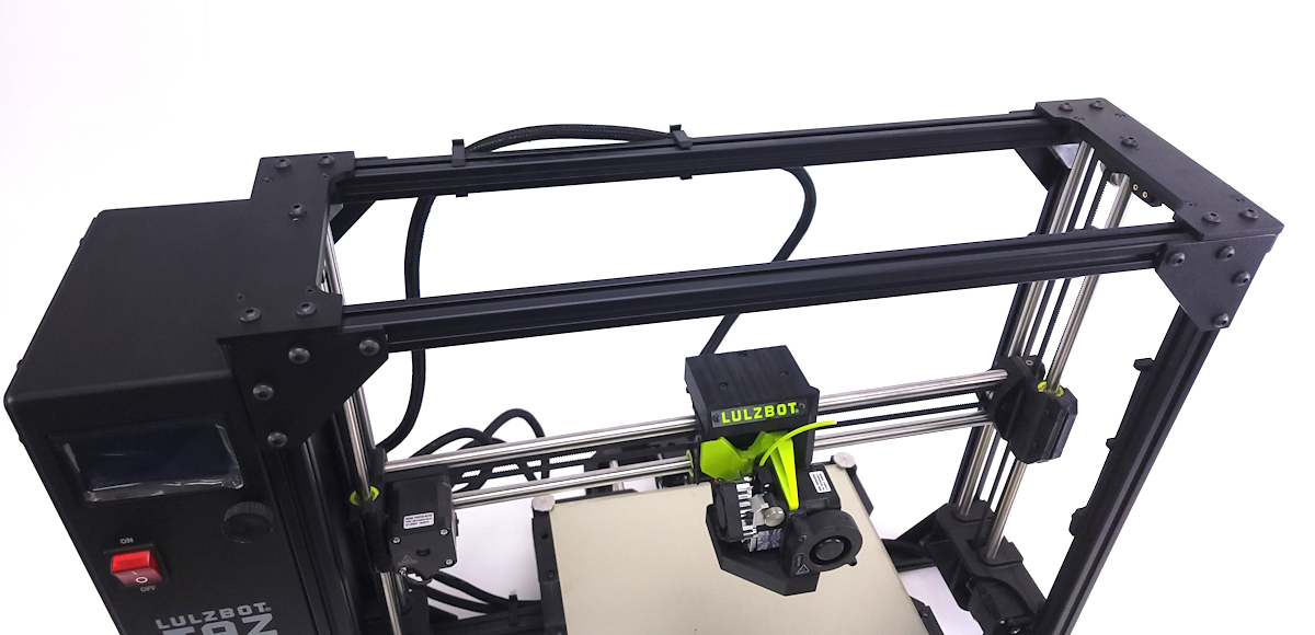
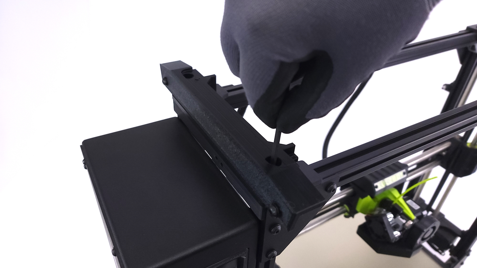
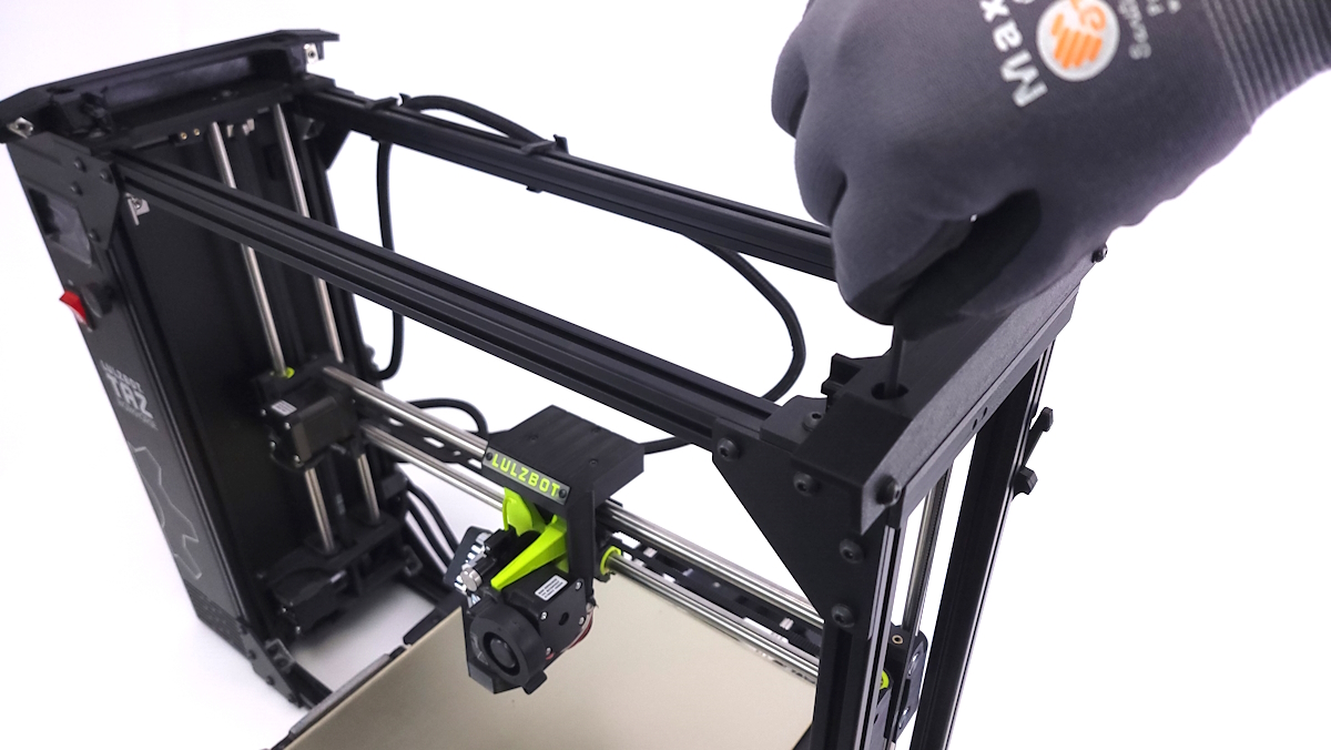
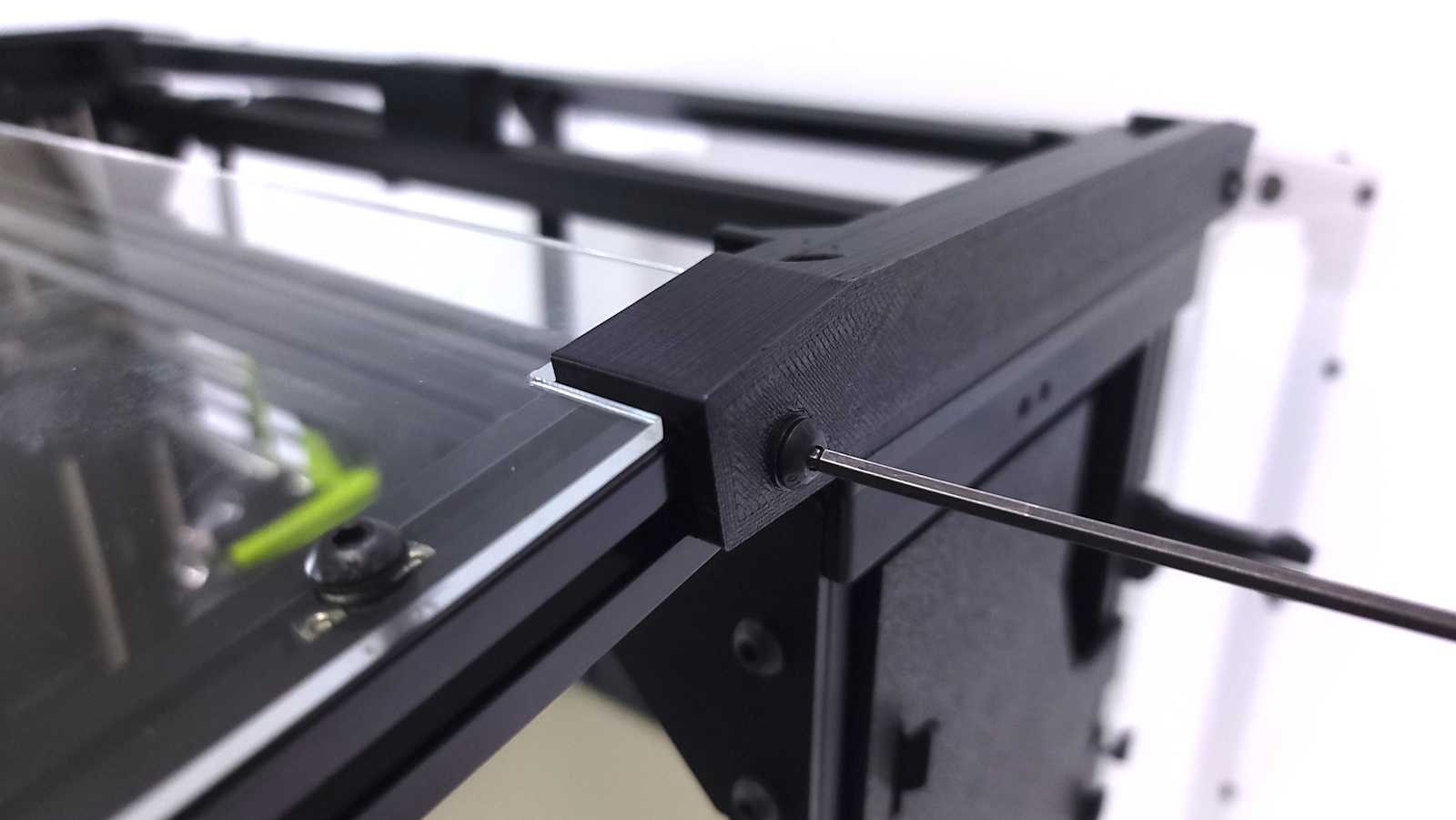
Once the brackets are prepped, begin by removing the 2 outermost screws on each side of the top of the printer using a 3mm hex wrench.
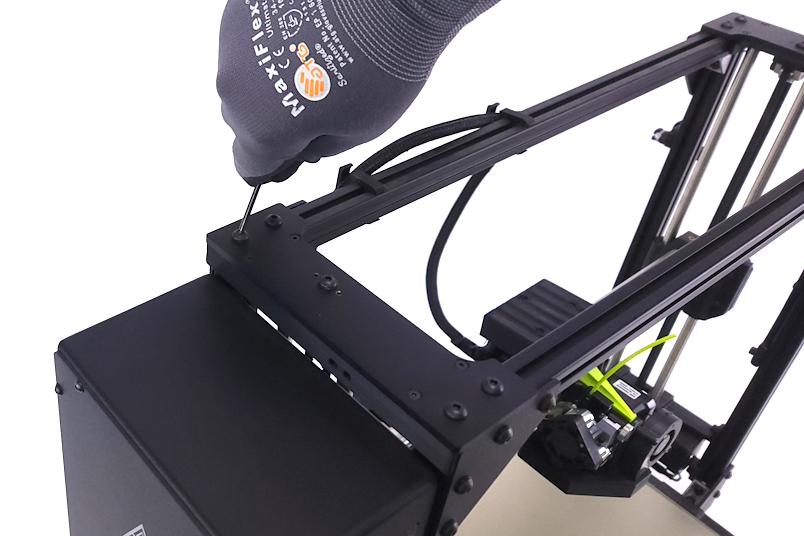
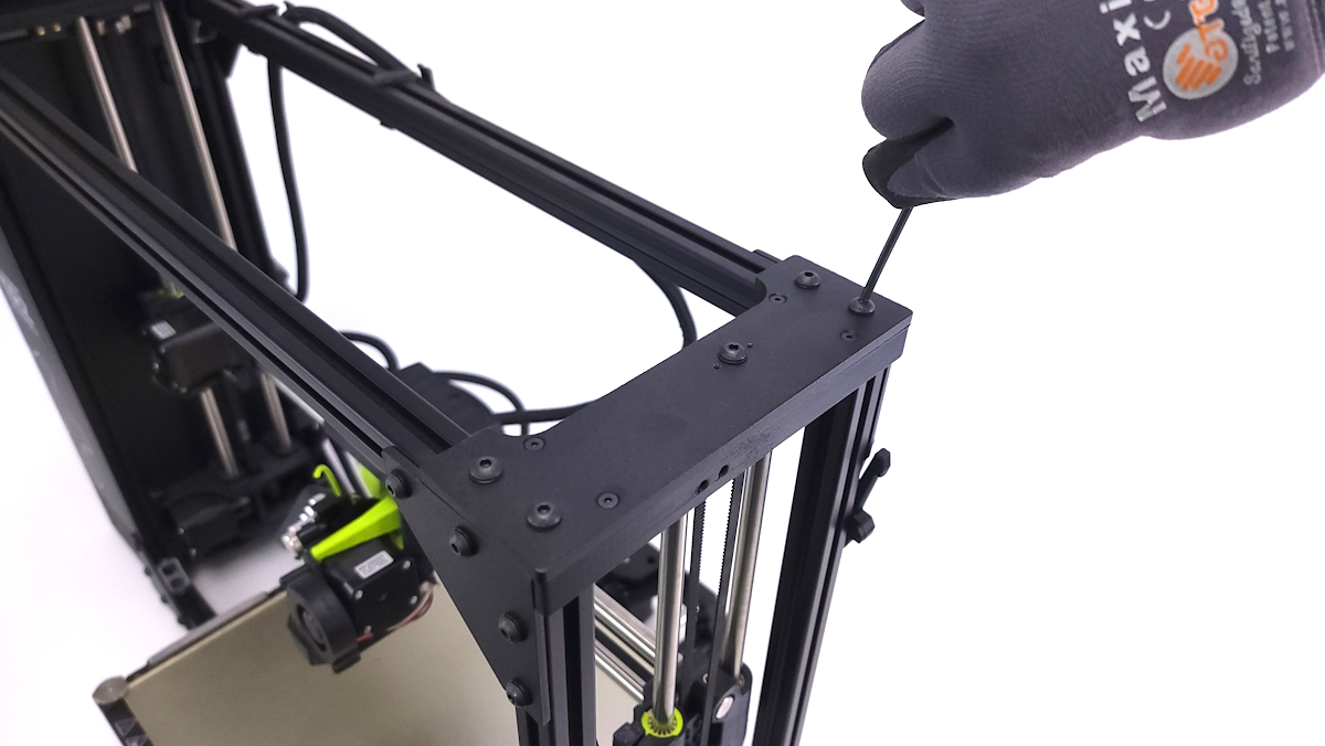
Using the included longer 4x socket head cap screws, washers, and 4mm hex wrench, secure the 3D printed bracket into the top of the printer's frame.
Do not over tighten as you can strip the extrusion threads.
Items required:
- 4x M5 Roll in T-nuts
- 4x M5 x 10mm BHCS
- 4x M5 Washers
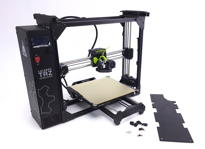
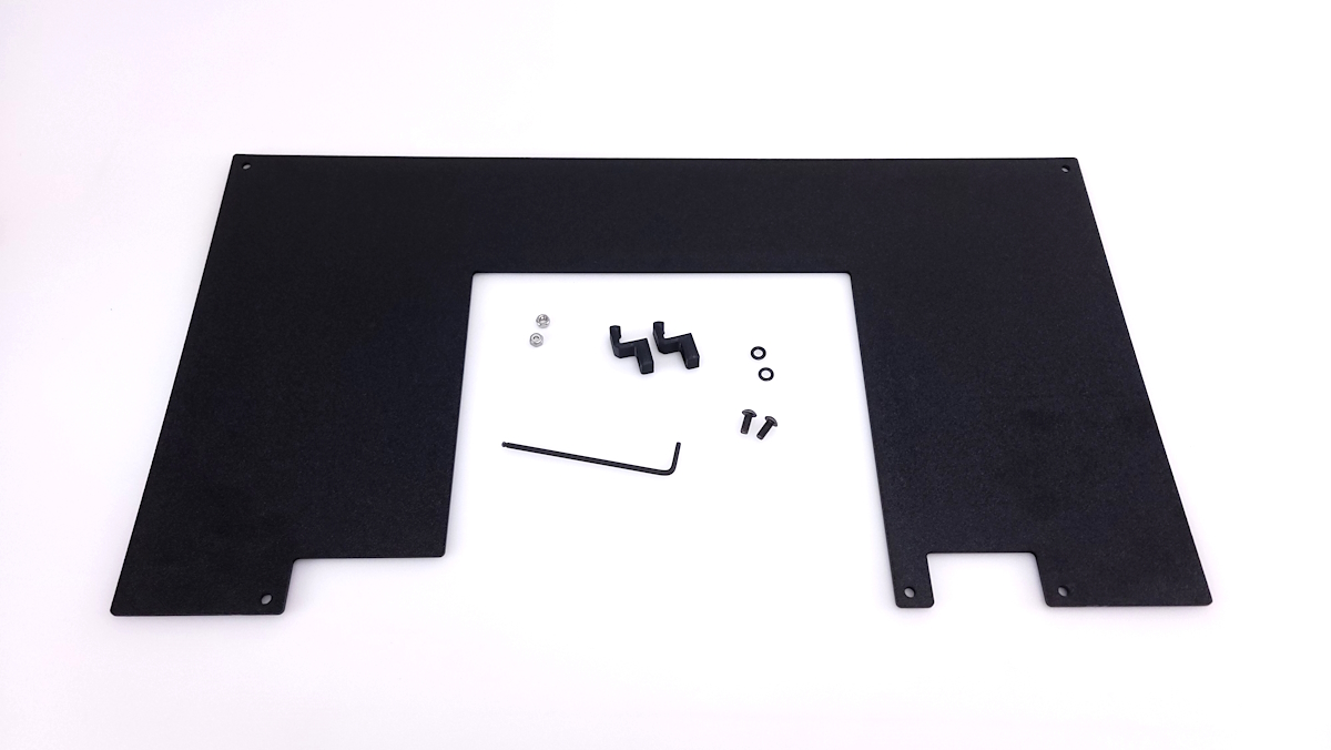
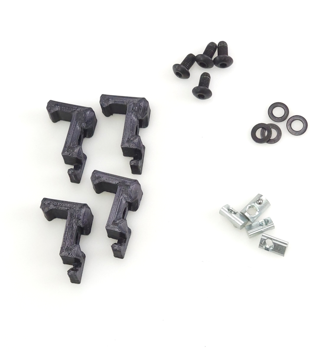
- 4x 3D Printed Side Panel mounts
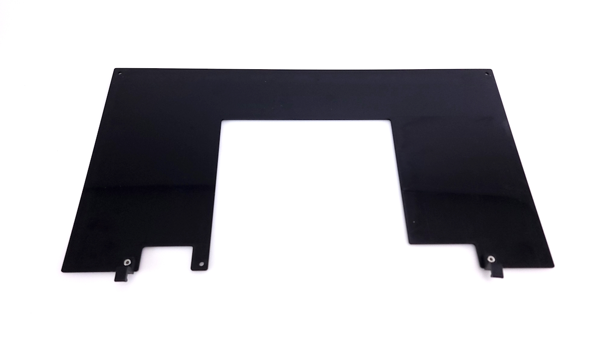
- 1x ABS Side Panel
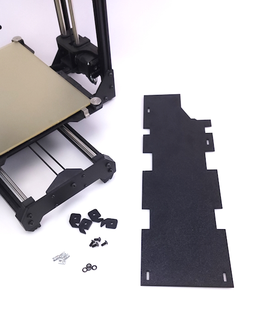
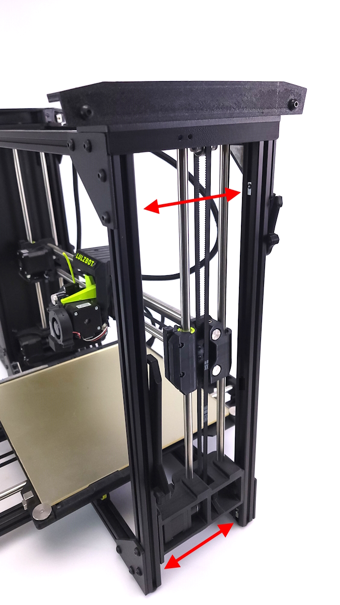
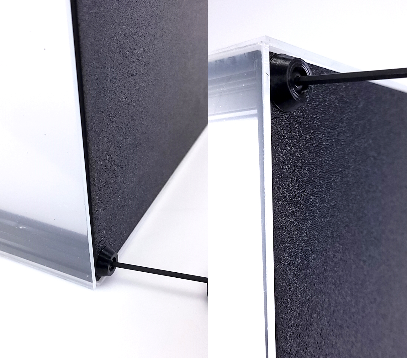
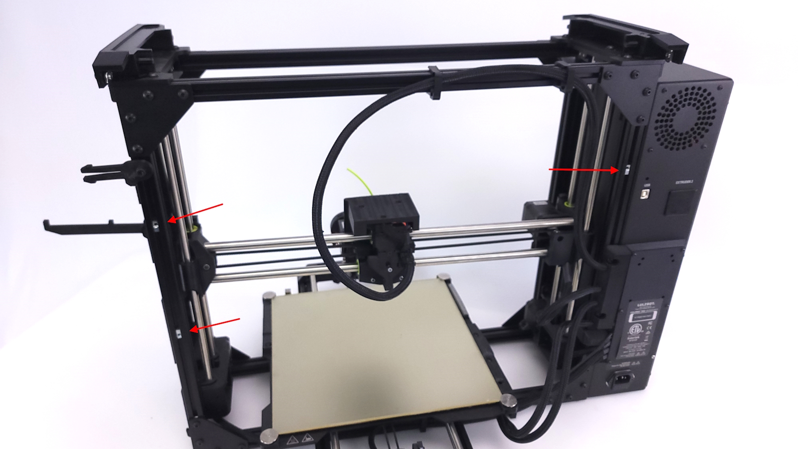
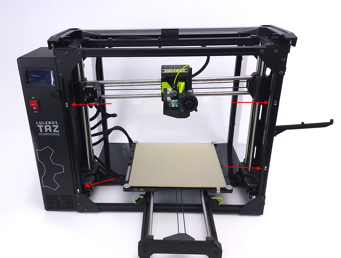
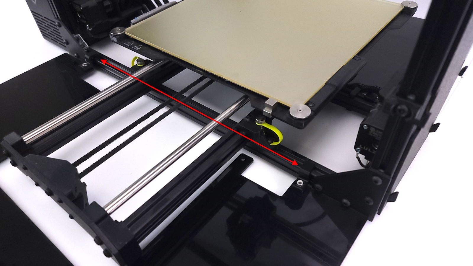
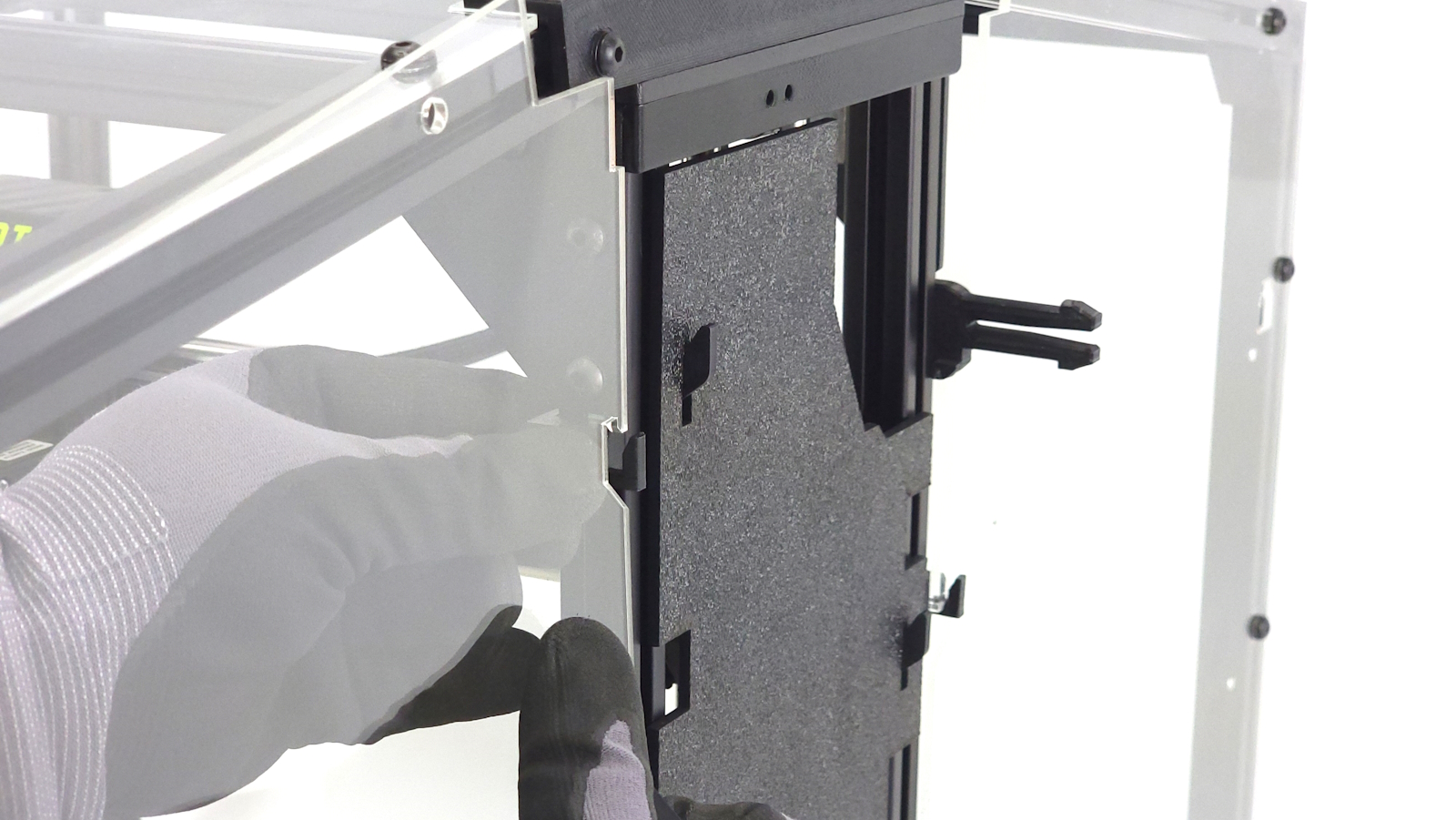
Take 4 of the roll in T-nuts and insert into the inside of the extrusion on the right side of the printer.
2 of the t-nuts will go somewhere near the top of the extrusion, and the other 2 t-nuts will go below the motor mounts.
Take the 4 m5 screws and put a washer onto each of them.
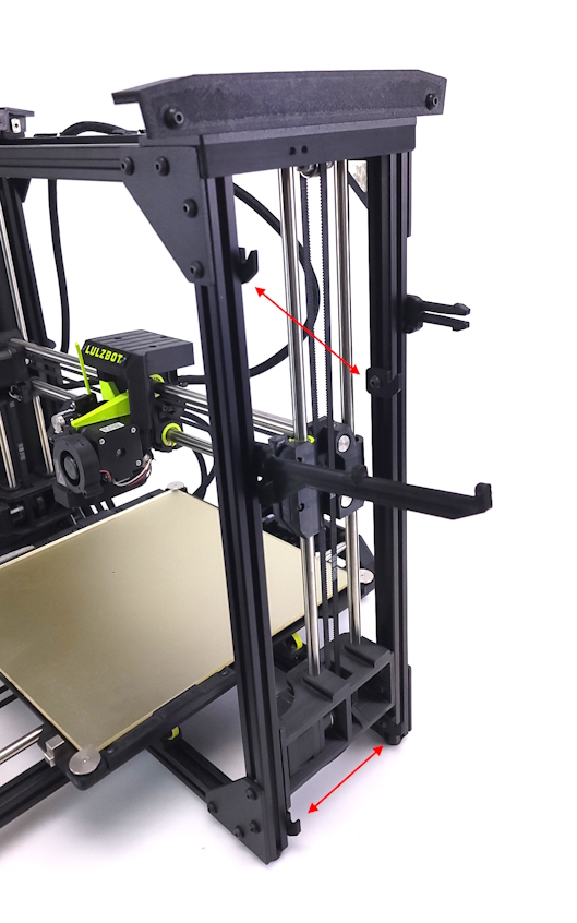
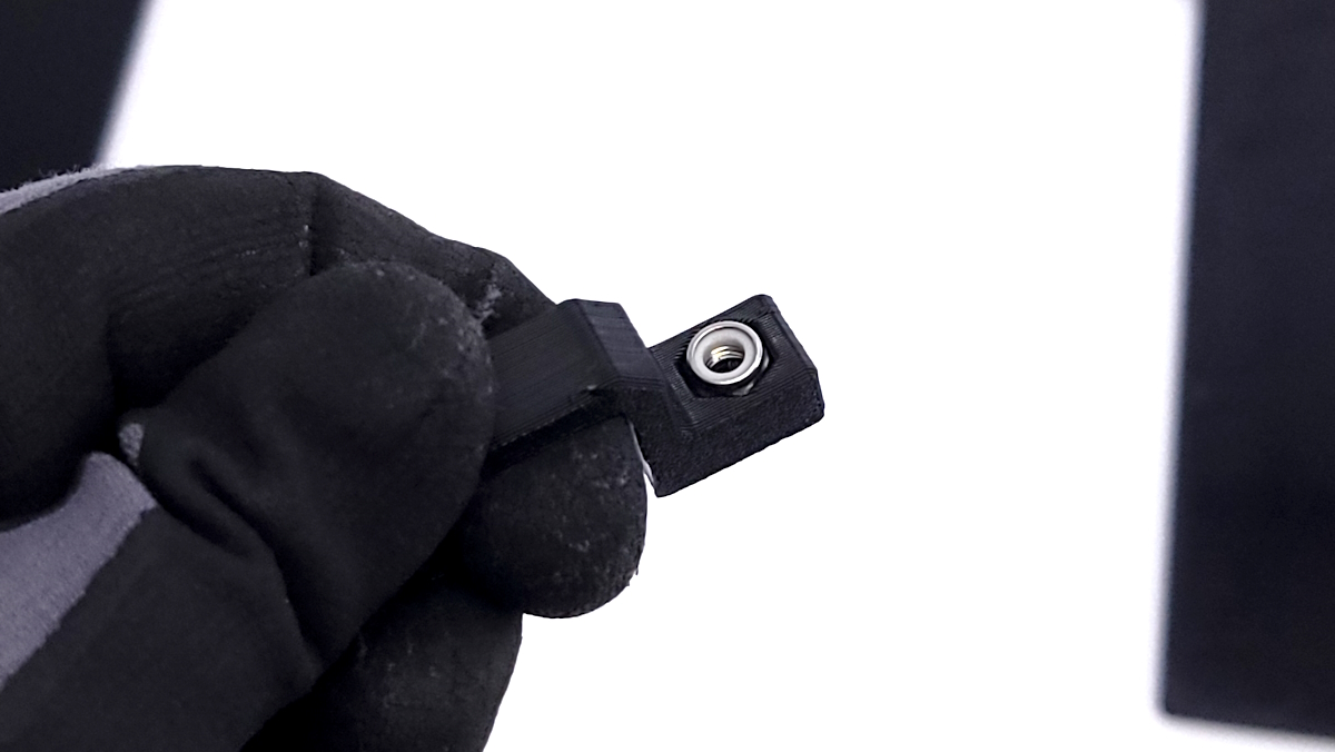
Take the 4 3D printed panel mounts and secure them to the printer using the 4 m5 screws previously prepared.
Orientate the mounts so the hooks face outwards and loosely secure to the frame. You should be able to slide them up and down with a little resistance.
Loosen the spool holder arm as well as the feed tube holder so you are able to move them up and down freely without them falling.
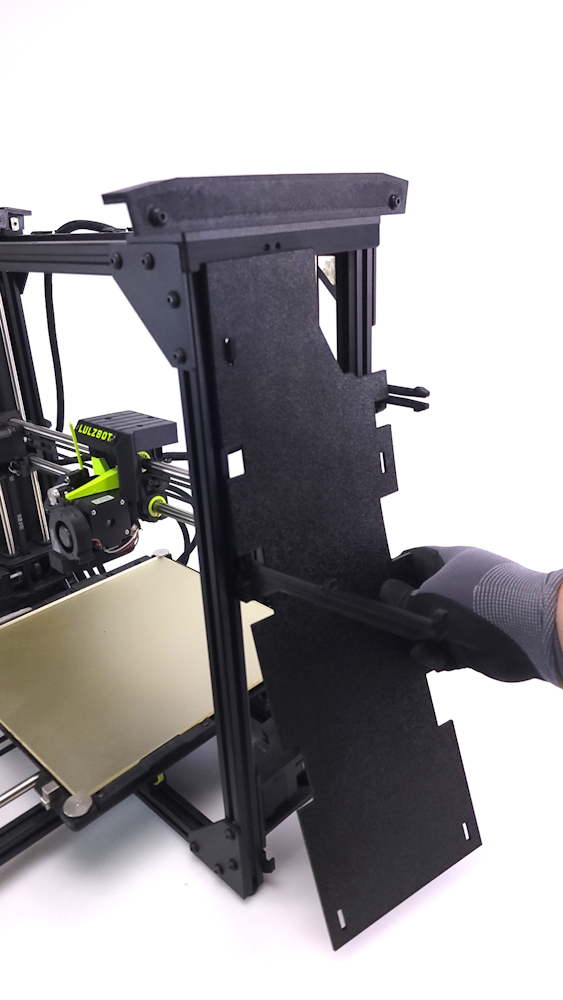
Take the black ABS side panel and set it close to the side of the printer and start aligning the side panel holders, spool arm, and feed tube holder until everything aligns properly and secure all 6 components.
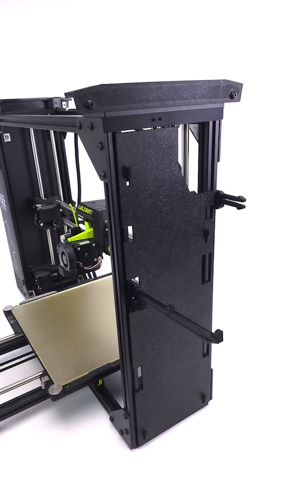
Once secured, install the side panel by aligning the hooks with the side panel and slide down to secure in place.
Note: TAZ Workhorse printers will have the textured side facing out, TAZ Pro users with the Jetpack runout sensor installed will have the smooth side facing out.
Parts needed:
- 1x Door Panel
- 1x Back Left Panel
- 1x Back Right Panel
- 1x Top Panel
- 11x Slide in T-nuts
- 11x M5 x 10mm BHCS
- 11x M5 washers
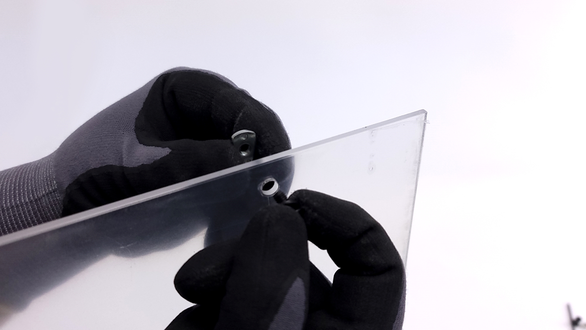
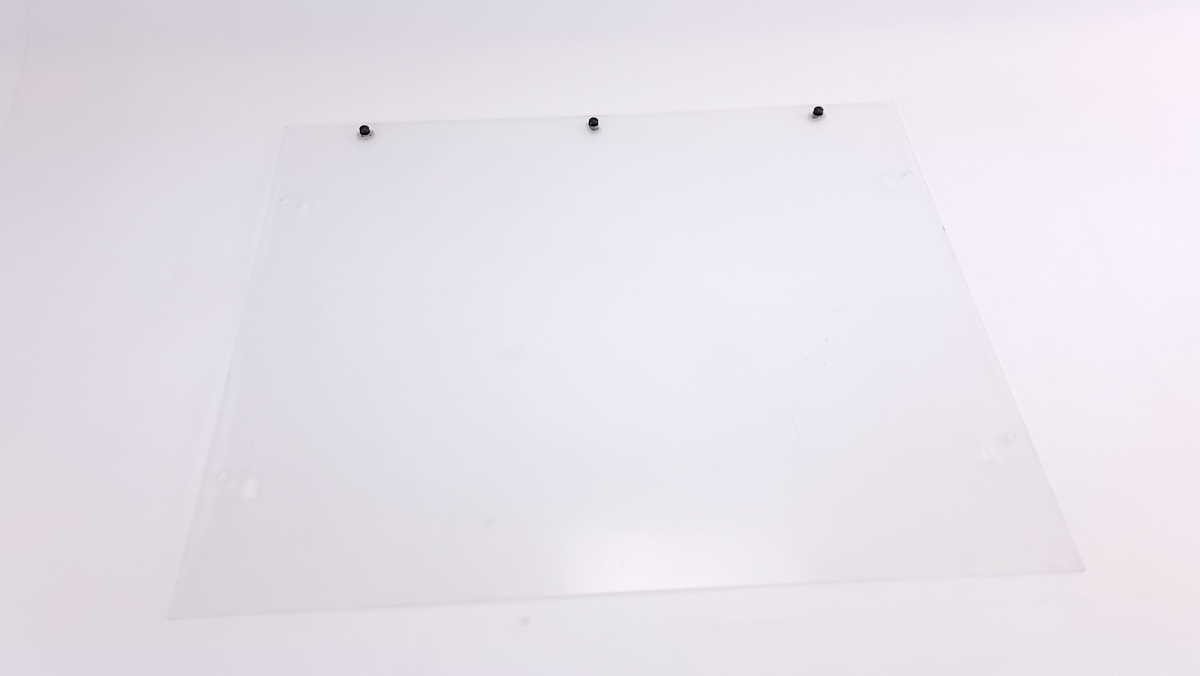
Secure 3 of the slide in t-nuts into the rear panel using 3x M5 screws and washers.
The t-nuts must be installed with the flat side facing the head of the screw to properly slide in the extrusions.
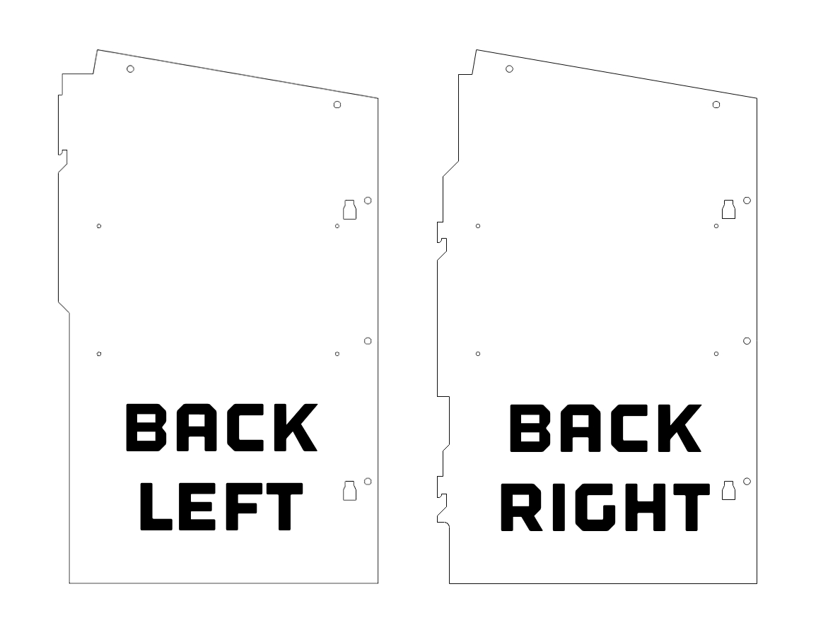
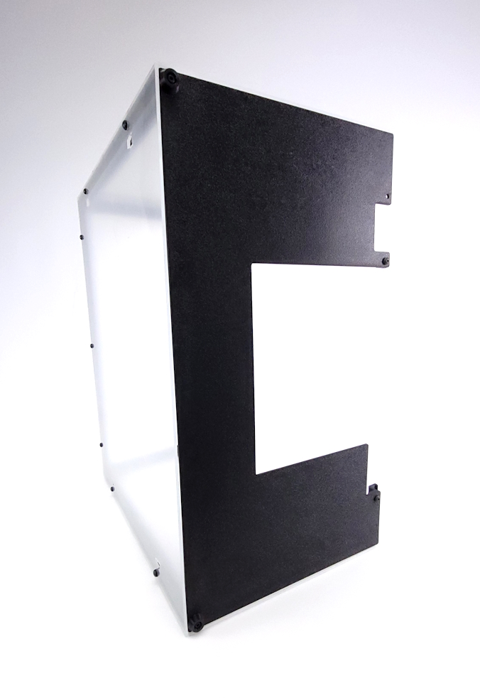
Locate the back left and back right panels. Note that they are different (see image for differences).
Secure 2 of the slide in t-nuts as previously into the top of each side panel.
The side that will have the t-nuts does matter. Refer to picture for correct orientation.
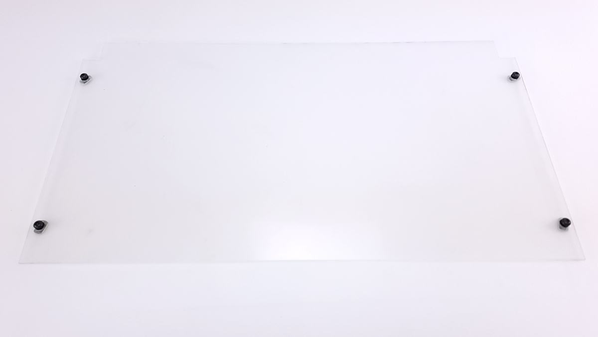
Use 4 screws, washers, and t-nuts to prepare the top clear panel for installation.
All hardware should be in the same orientation.
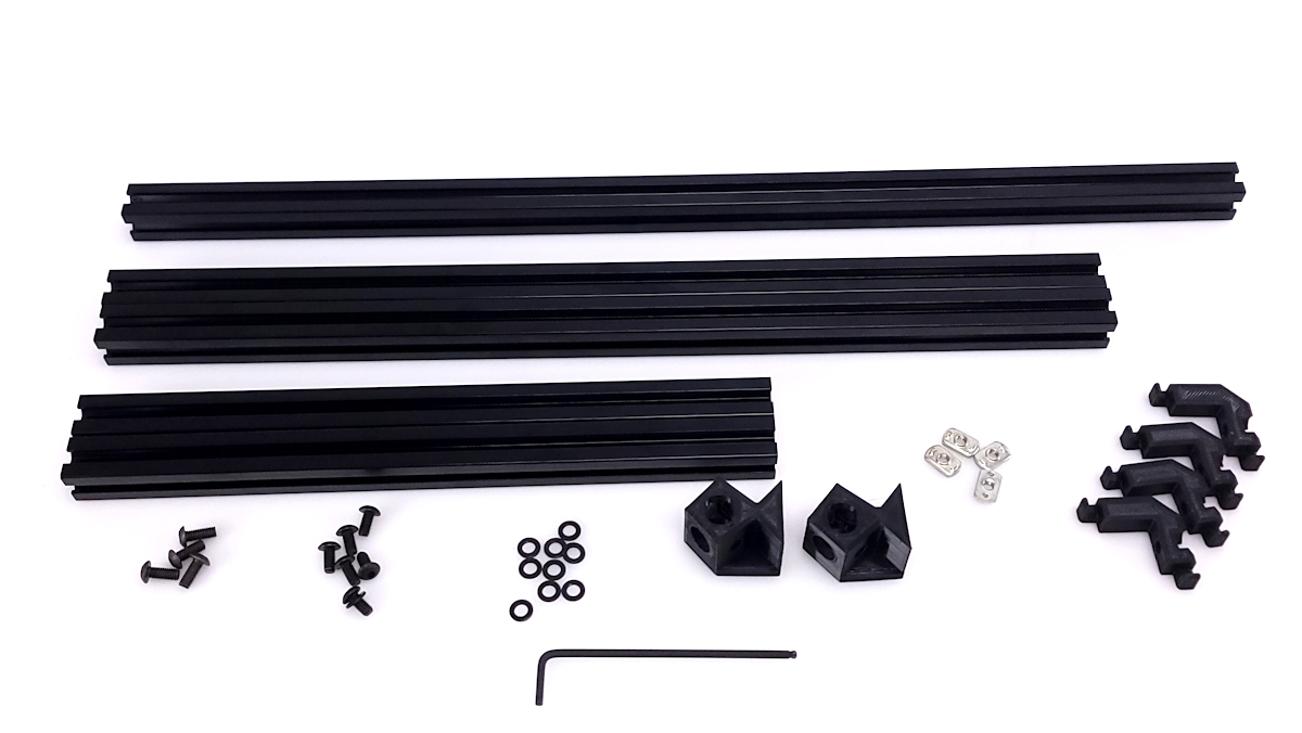
Parts required:
- 1x Bottom Panel
- 1x Door Panel
- 1x Back Left Panel
- 1x Back Right Panel
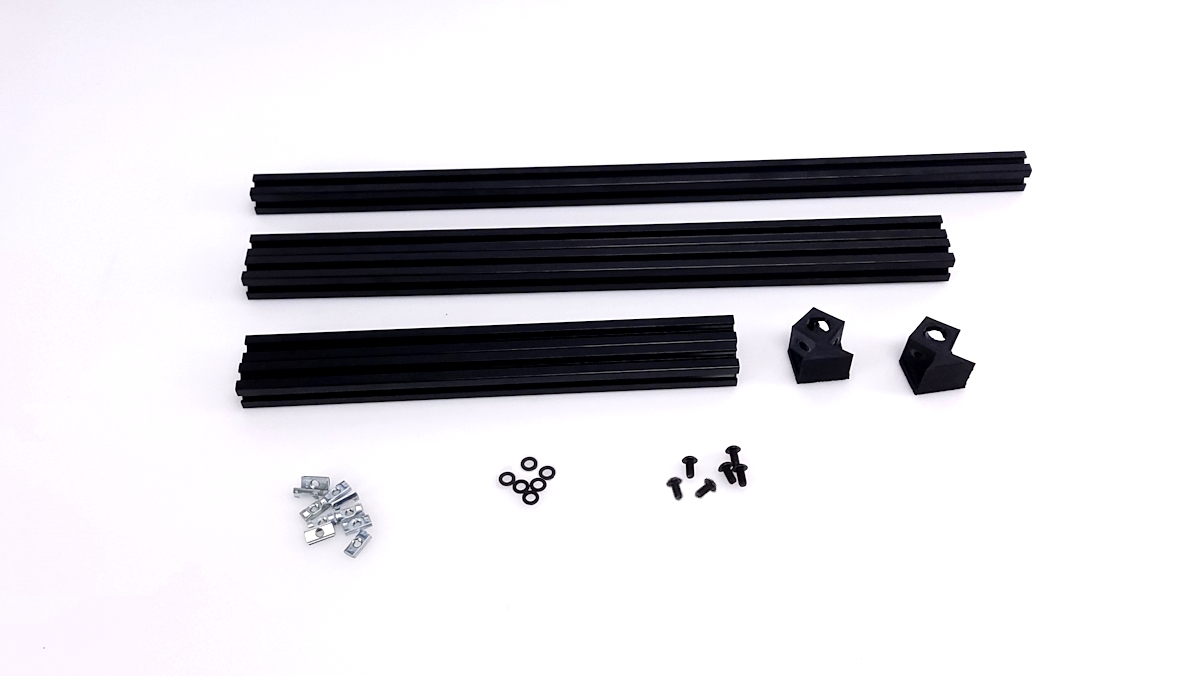
- 2x 294mm Extrusion
- 2x 447mm Extrusion
- 1x 522mm Extrusion
- 2x 3D printed corner tabs
- 2x 3D Printed Feet
- 2x M5 Nyloc nut
- 10x M5 Post assembly T-nuts
- 21x M5x10mm BHCS
- 2x M5x12mm BHCS
- 23x M5 Washers
- 4x M5 Slide in T-nuts
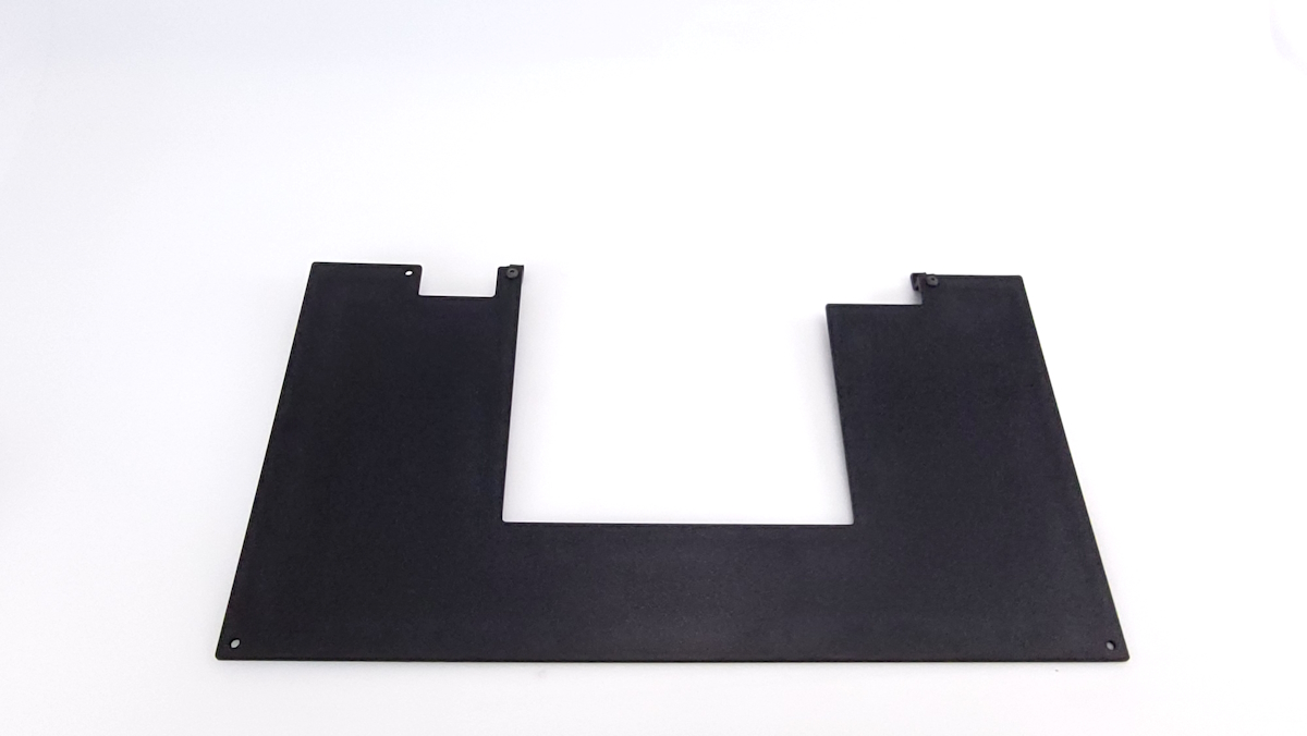
Locate 1 of the black ABS bottom panels.
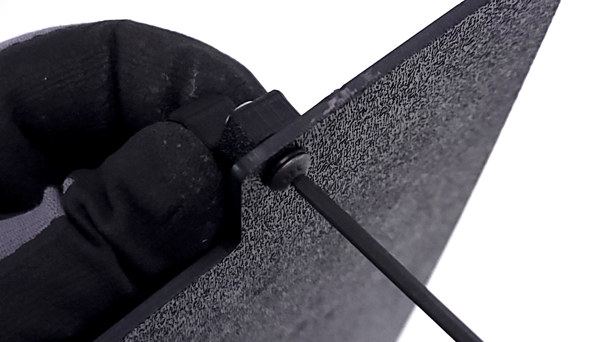
Begin by inserting 2 nyloc nuts into the 3D printed extrusion clips.
Using the longer M3x12mm screws and washers, secure the clips to the bottom abs panel with the textured surface being the side that the washer is contacting.
For the rear bottom panel, the clip will be located on the innermost holes on the side with 2 locations.
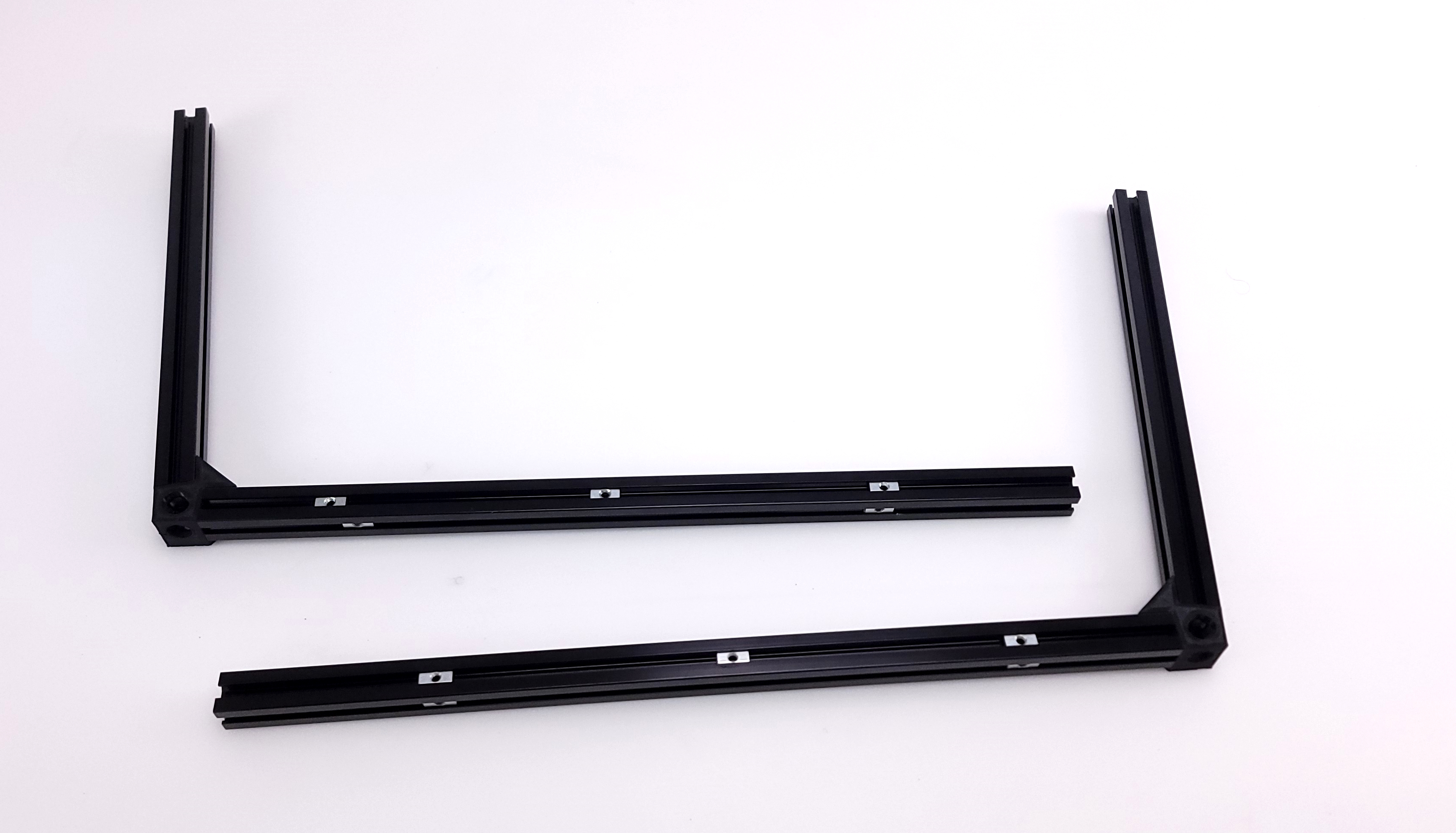
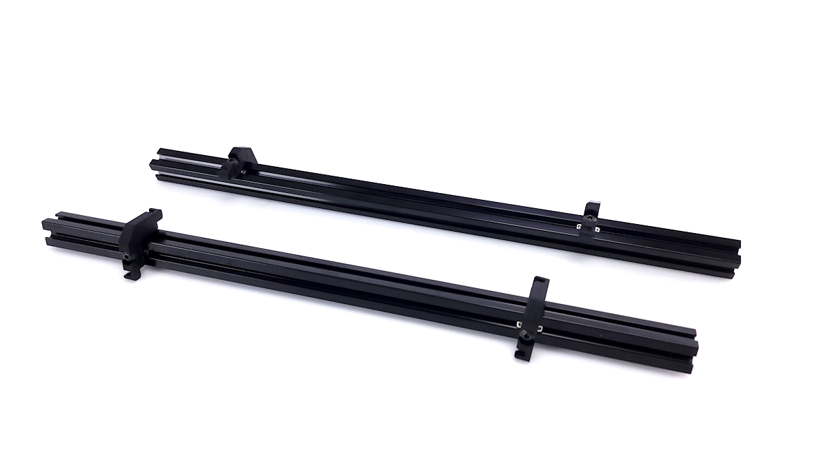
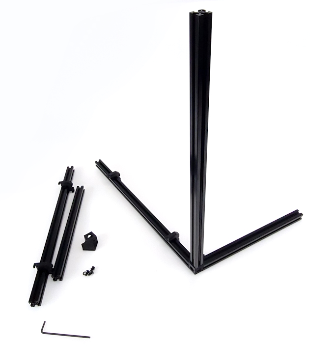
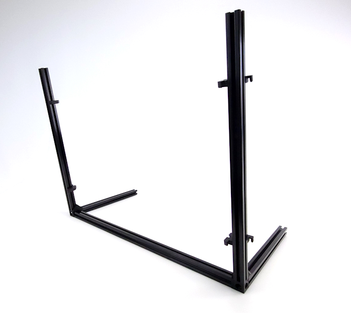
Locate the necessary extrusion, printed parts, and hardware for the frame.
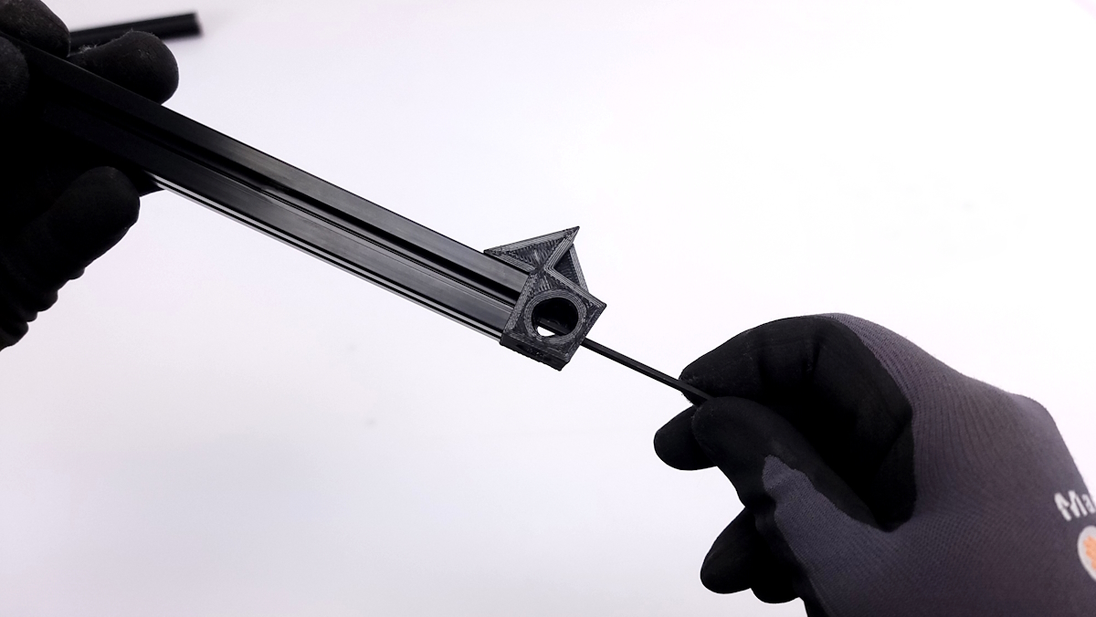
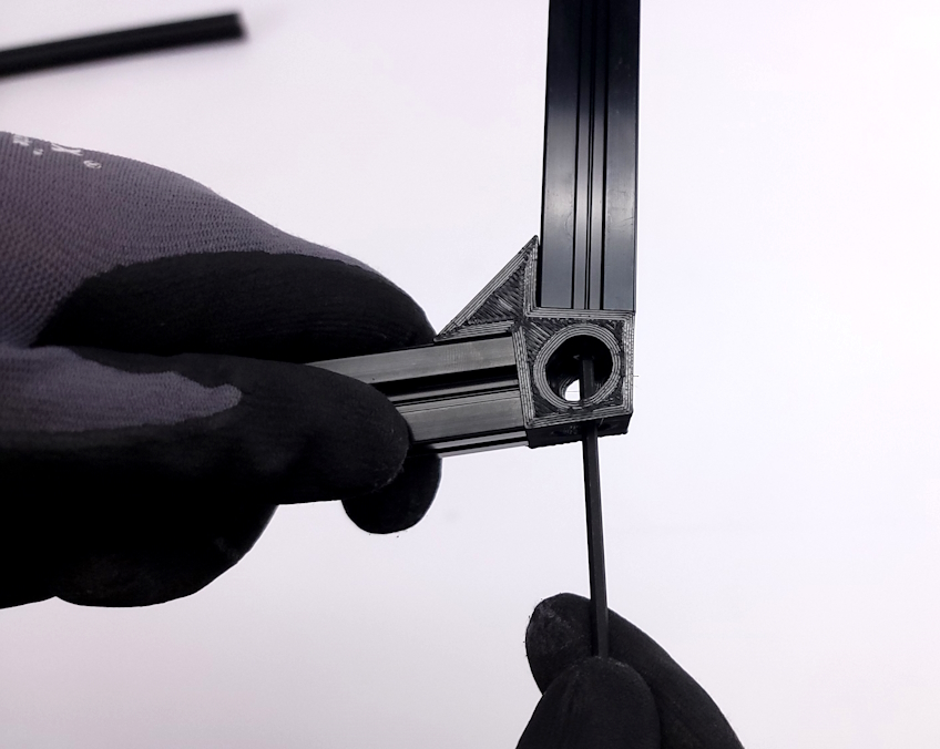
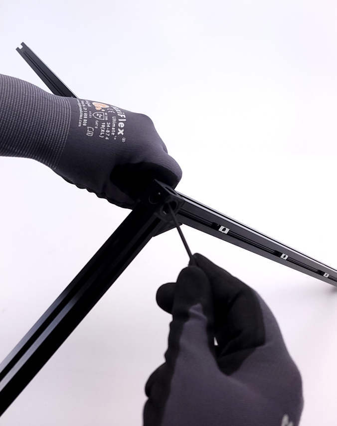
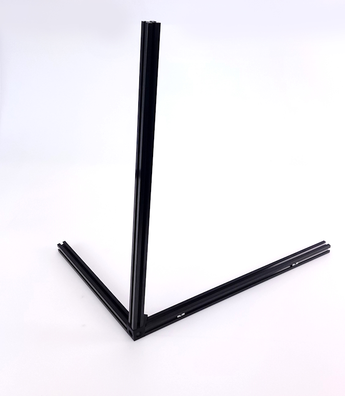
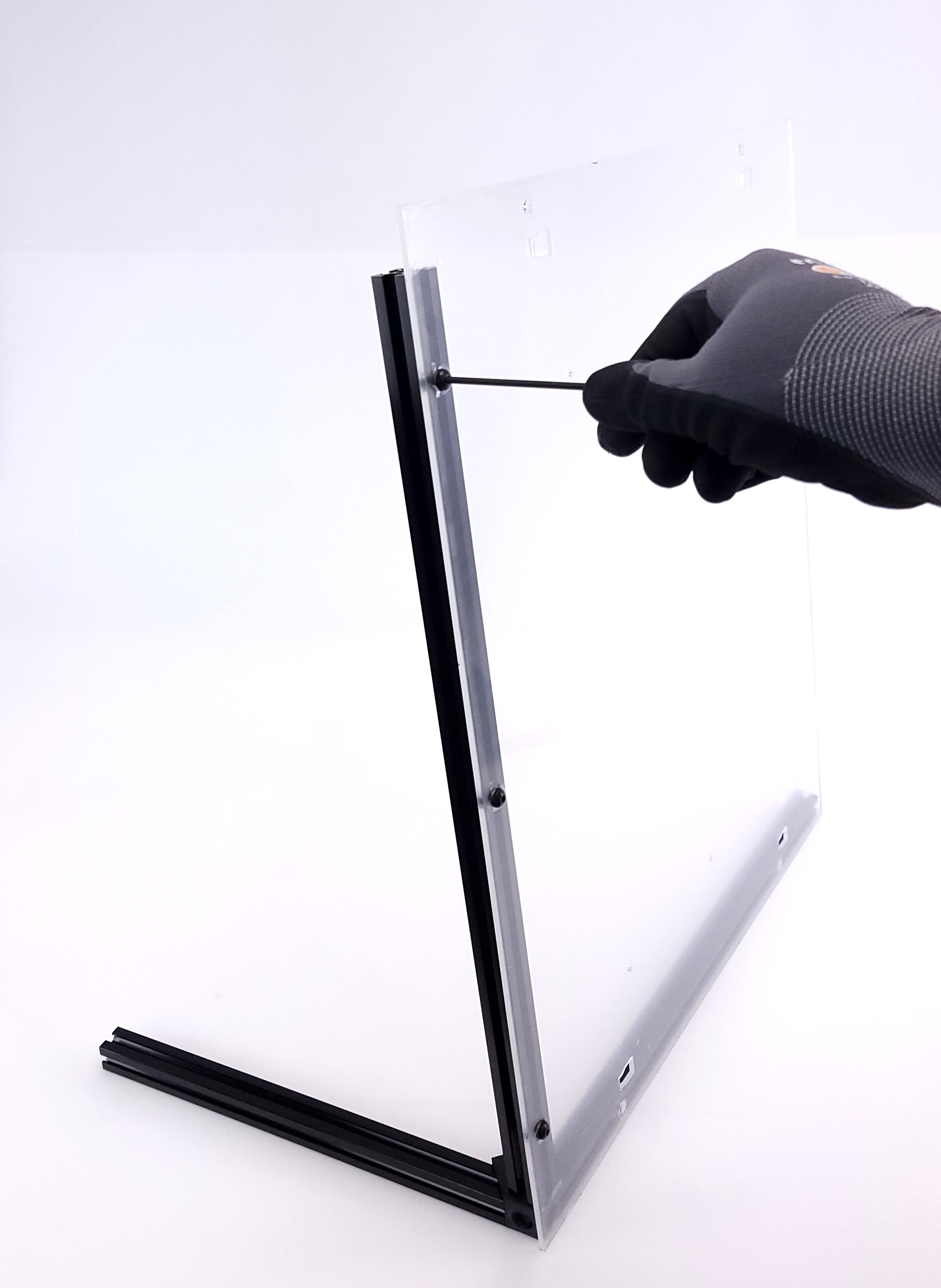
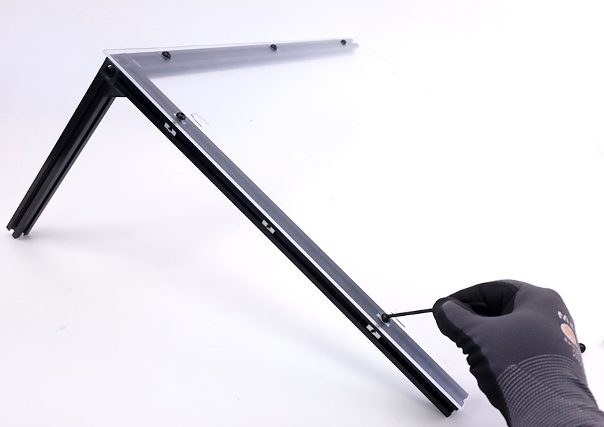
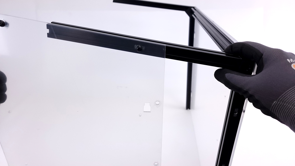
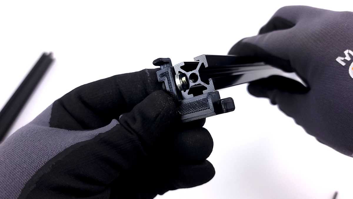
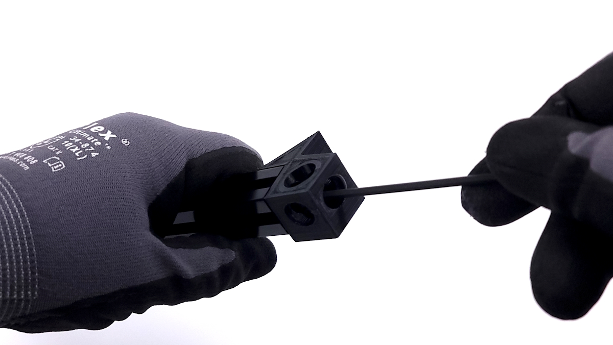
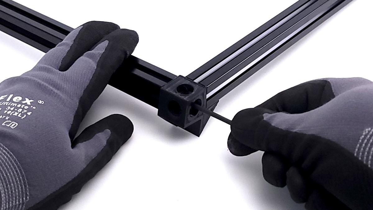
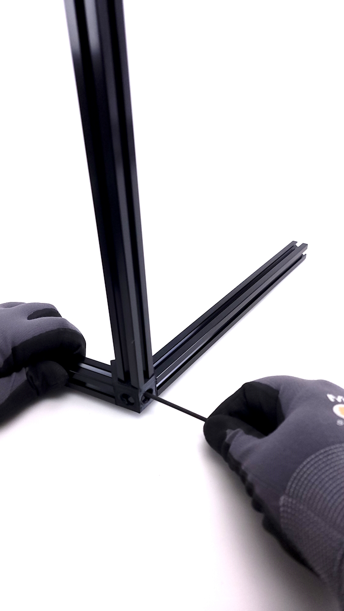
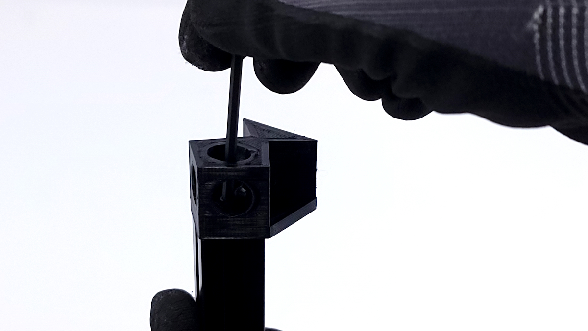
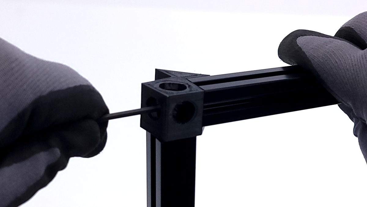
Using the M5x10mm screws and washers, secure the 477mm extrusion to the corner brackets.
Attach the smaller 294mm extrusion to the corner bracket as well at a ~90° angle.
Note: Only 1 side of the short extrusions have threads. Please check before attempting to install a screw into the wrong side of the extrusion.
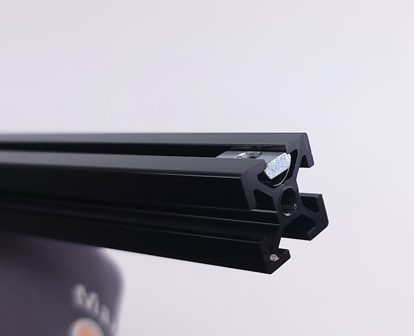
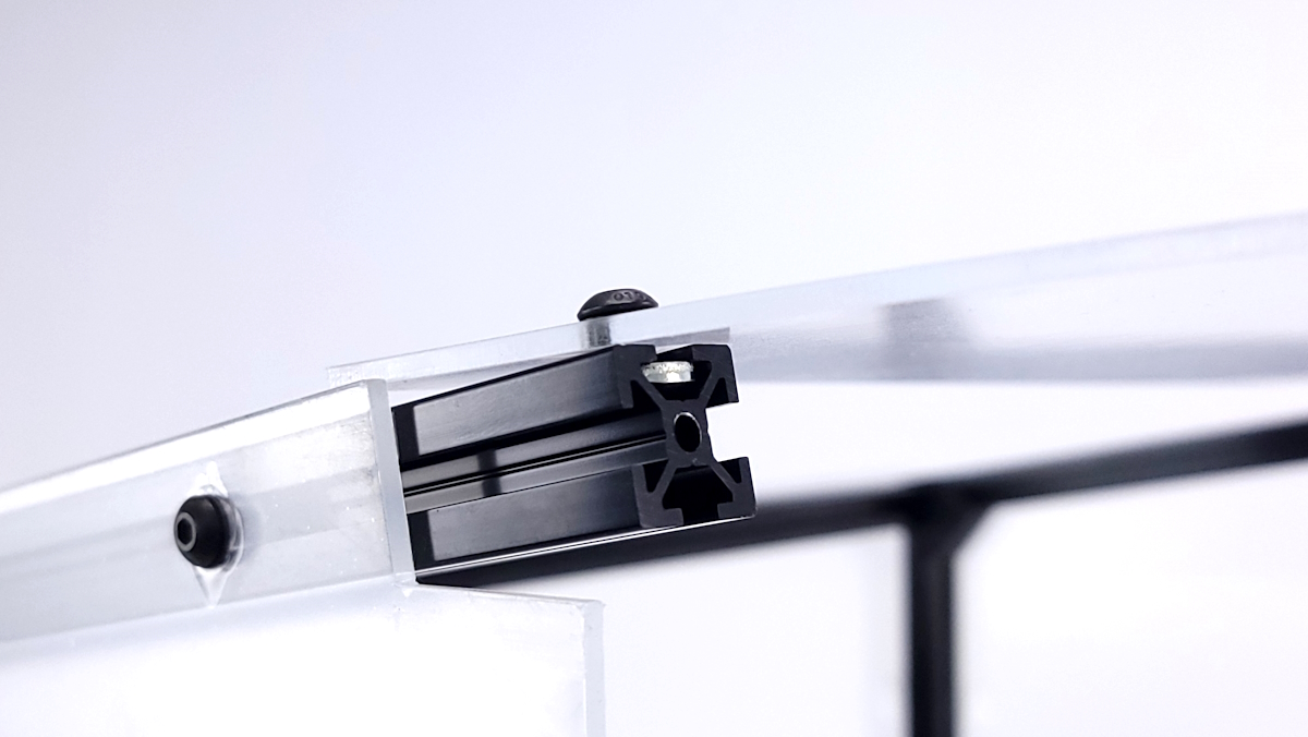
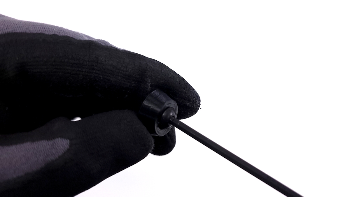
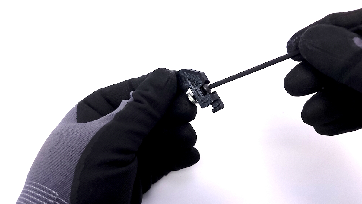
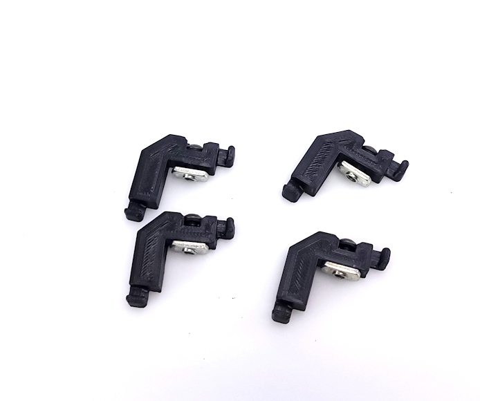
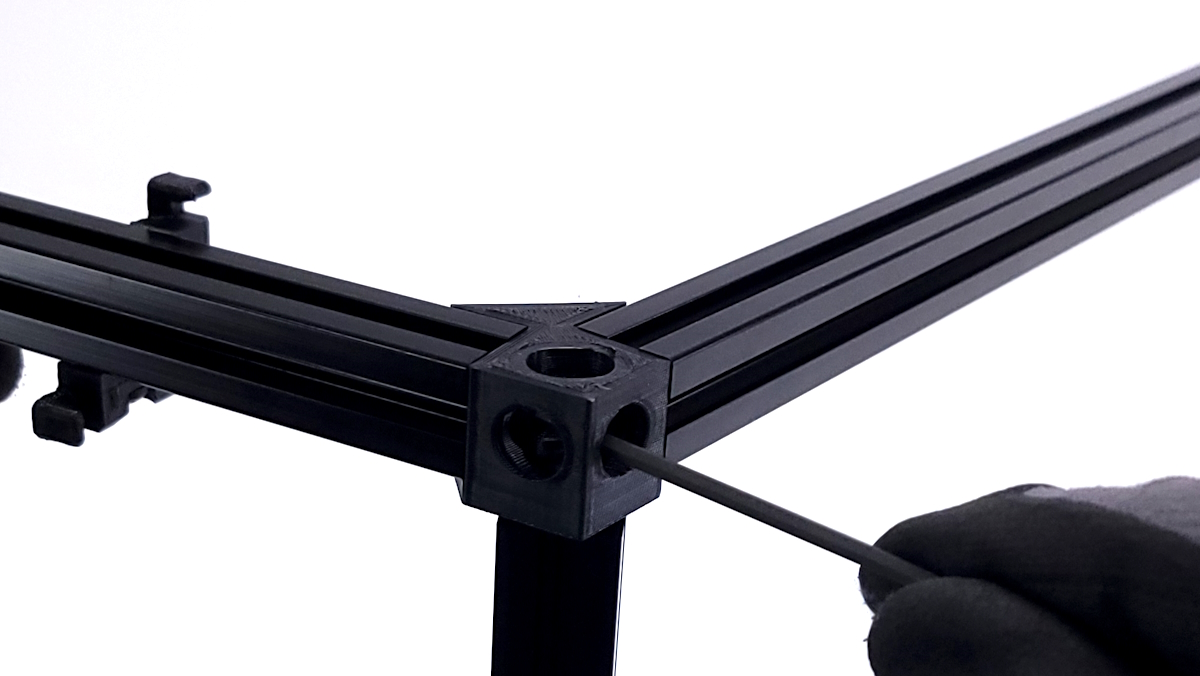
Slide the post assembly t-nuts (ones with a spring on the back them to hold them in position) into the 477mm extrusions.
3 nuts will go into the side of the extrusion, 2 more nuts will go into the front of the extrusion.
See picture for correct orientation
Secure longer extrusion into one of the brackets just assembled.
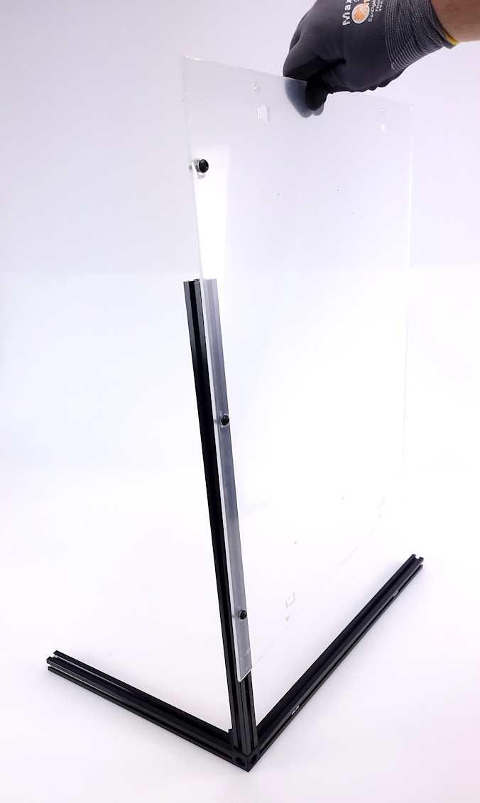
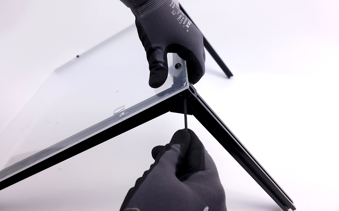
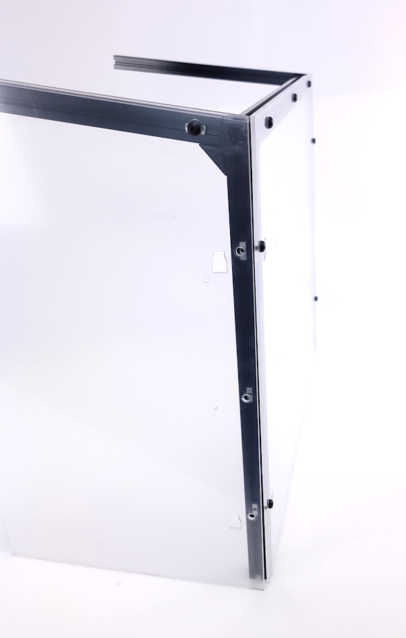
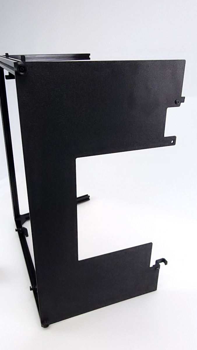
Take the rear panel and slide the panel down into the frame.
The T-nuts should smoothly slide into the extrusion without resistance. If there is resistance, you may need to loosen the nuts a little to allow for more clearance.
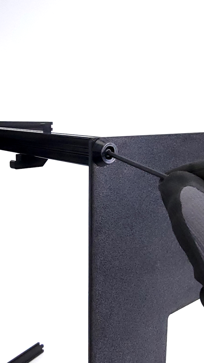
Secure the panel by tightening down the 3 screws. Do not overtighten.
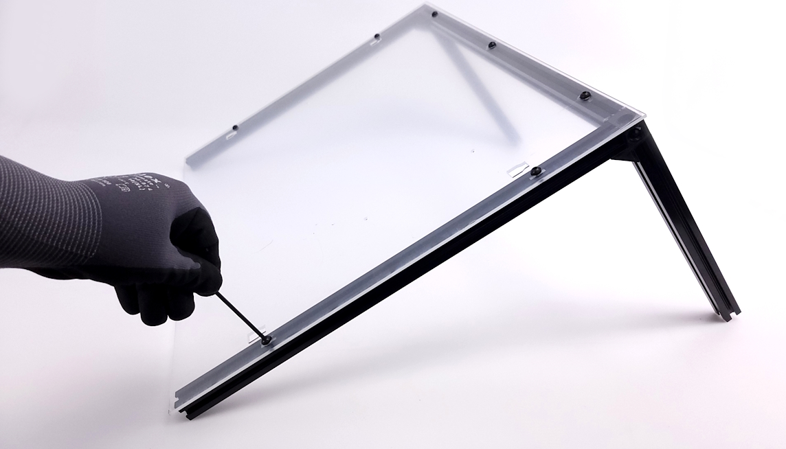
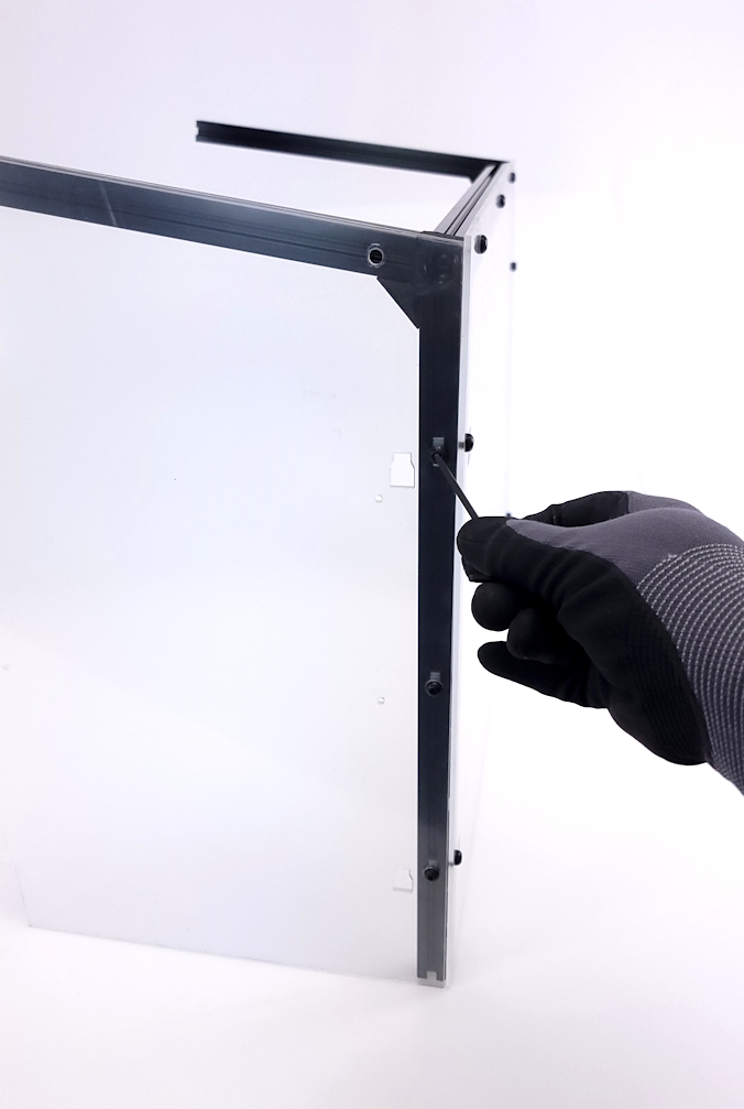
Using additional m5 hardware, secure the side of the panel using 2 screws and washers and securing through the panel and into the t-nuts.
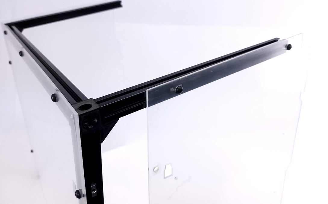
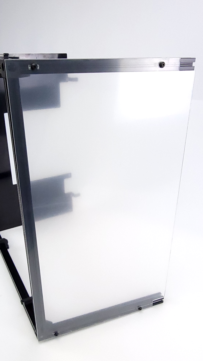
Install the second bracket into the longer extrusion from the opposite side.
Secure clear panel to bracket using 2 screws and washers.
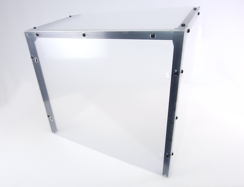
Take the back left and right panels and slide them into the short extrusion on both sides of the frame.
You may need to adjust the location of the previously installed t-nuts before tightening down all screws, so align all t-nuts with the corresponding holes before inserting and tightening down all 5 screws on both the back left and right clear panels.
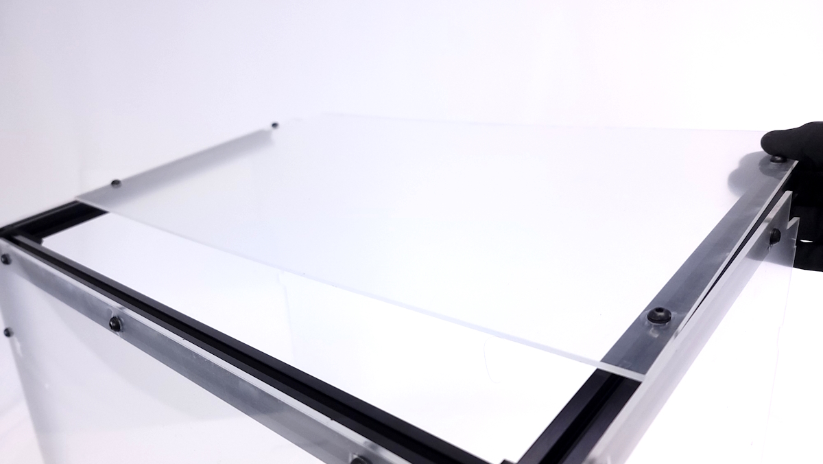
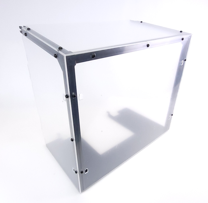
Take the top panel and slide that into position with the t-nuts sliding into the top of the extrusion.
Tighten all 4 screws once in position.
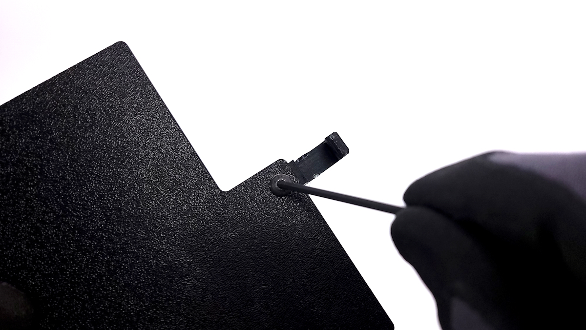
Install a M5 screw and washer through the 3D printed feet and secure lower black panel to the extrusions. The textured side of the panel should be facing down.

Parts required:
- 12x M3x8mm screws
- 12x M3 washers
- 4x M5x10mm screws
- 4x M5 washers
- 4x slide in t-nuts
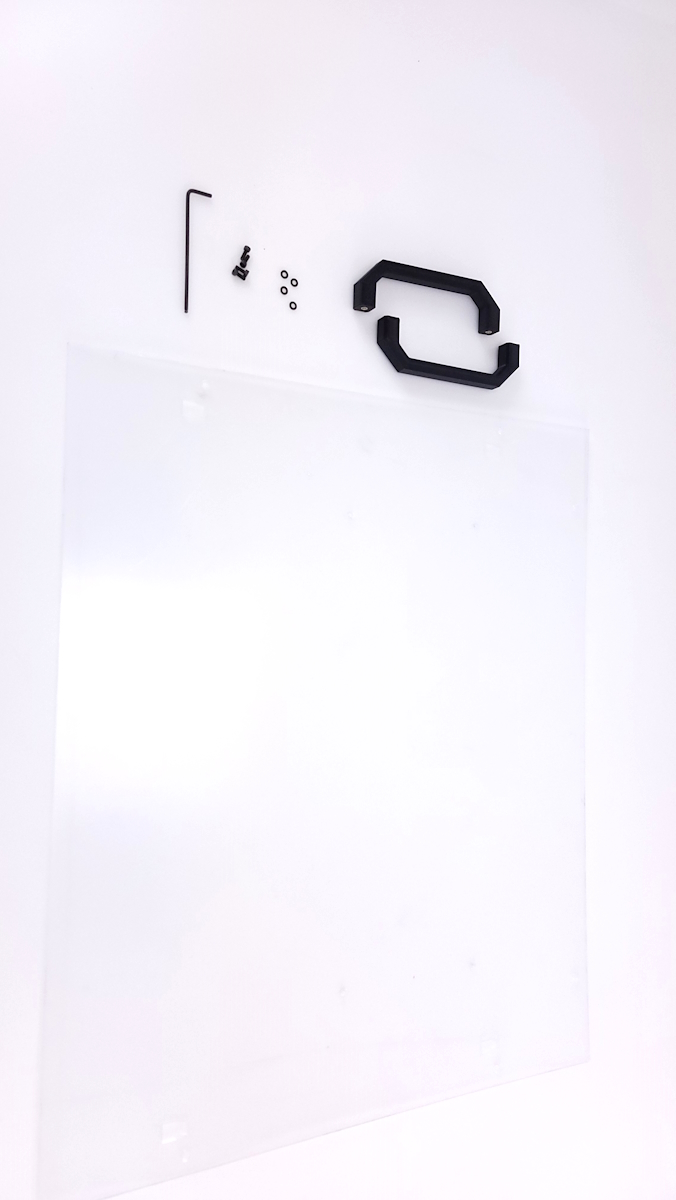
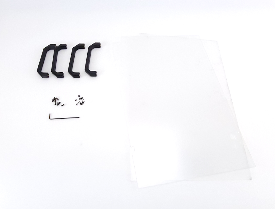
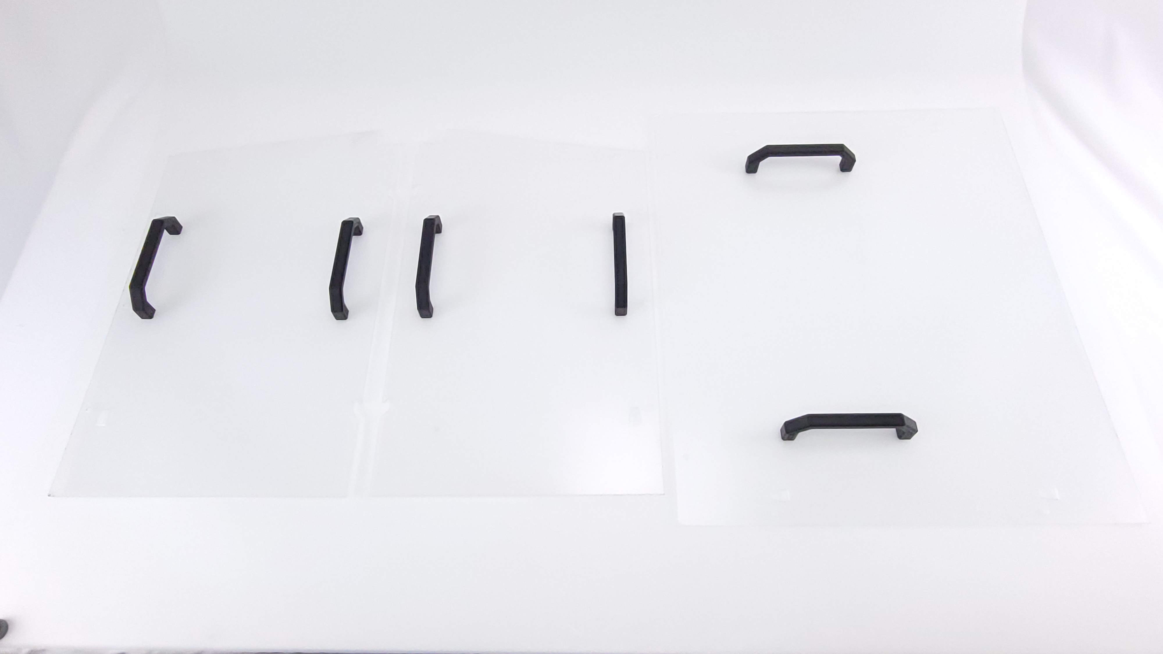
- 6x 3D printed handles
- 2x front side panels
- 1x top panel
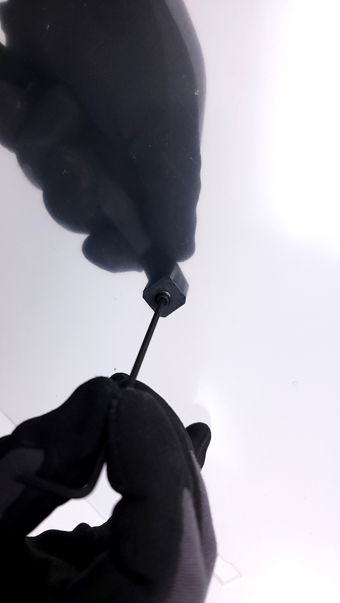
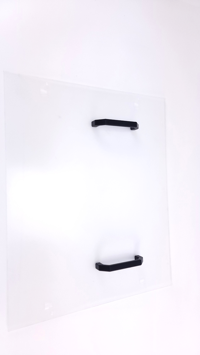
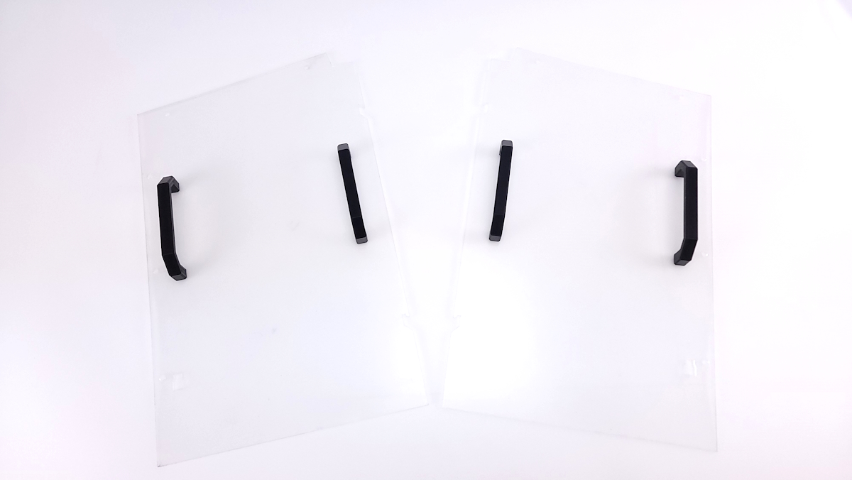
Using an M3x8mm screw, and washer, secure the both handles to the side panels and front clear panel.
The Side panels should mirror each other when sitting flat.
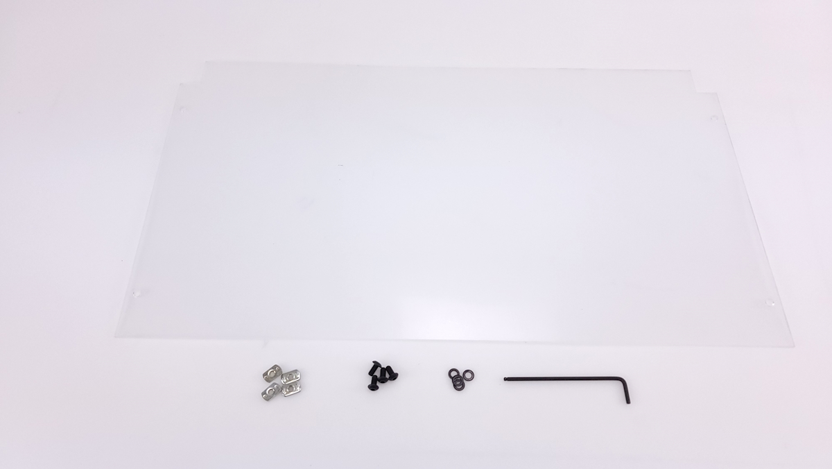
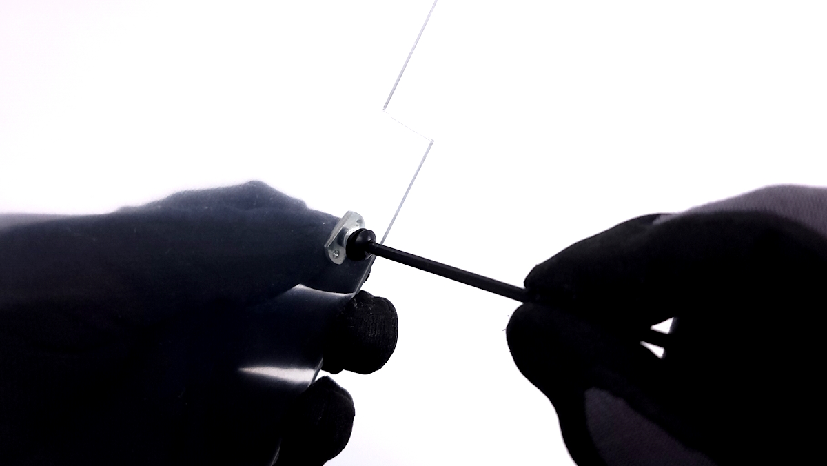
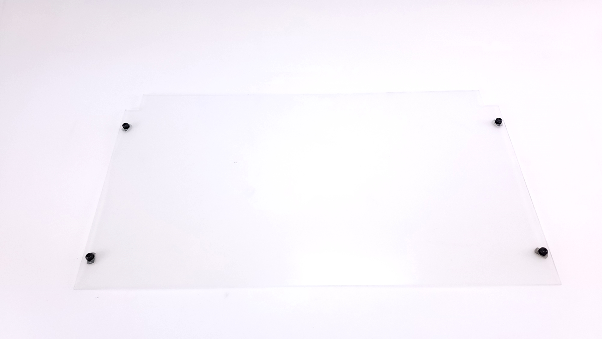
Use the 4x M5x10mm screws and washers, mount the slide in t-nuts through the top panel.
Parts required:
- 1x Bottom Panel
- 1x Door Panel
- 2x Front Side Panel
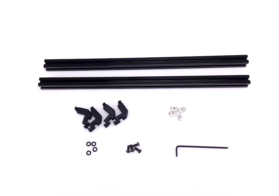
- 2x 294mm Extrusion
- 2x 447mm Extrusion
- 1x 522mm Extrusion
- 2x 3D printed corner tabs
- 2x 3D Printed Feet
- 2x M5 Nyloc nut
- 6x M5x10mm BHCS
- 2x M5x12mm BHCS
- 12x M5 Washers
- 8x M5 Slide in T-nuts
Locate the black ABS bottom panel.
Inserting 2 nyloc nuts into the 3D printed extrusion clips.
Using the longer M5x12mm screws and washers, secure the clips to the bottom abs panel with the textured surface being the side that the washer is contacting.
For the rear bottom panel, the clip will be located on the outermost hole on the side with 2 locations.
Locate the necessary extrusion, printed parts, and hardware for the frame.
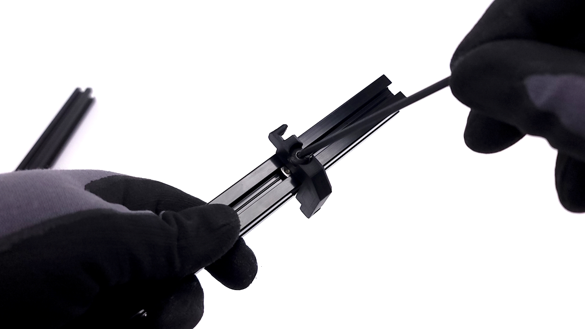
Prepare the 4 clear panel mounts by threading 4 M5x10 screws and washers through them mounts and secure with a slide in t-nut, flat side facing the print.
Locate the 2 447mm extrusions and slide 2 of the panel mounts into the extrusion.
Both mounts need to be in the same slot and in the same orientation.
Tighten them down a little bit to secure them to the extrusion while handling
Using the M5x10mm screws and washers, secure the 477mm extrusion to the corner bracket.
Attach the smaller 294mm extrusion to the corner bracket as well at a ~90° angle.
Note: Only 1 side of the short extrusions have threads. Please check before attempting to install a screw into the wrong side of the extrusion.
Secure longer extrusion into the bracket just assembled.
See picture for correct orientation of the panel mounts, they should be facing inside of the assembled frame.
Install the second bracket into the longer extrusion from the opposite side.
Assemble the extrusions to mirror the opposite side.
Take the top panel and slide that into position with the t-nuts sliding into the top of the extrusion.
Tighten all 4 screws once in position.
Install a M5 screw and washer through the 3D printed feet and secure lower black panel to the extrusions. The textured side of the panel should be facing down.


Parts required:
- 7x M5x10mm screws
- 7x M5 washers
- 7x roll in t-nuts
- 7x 3D printed clear panel mounts
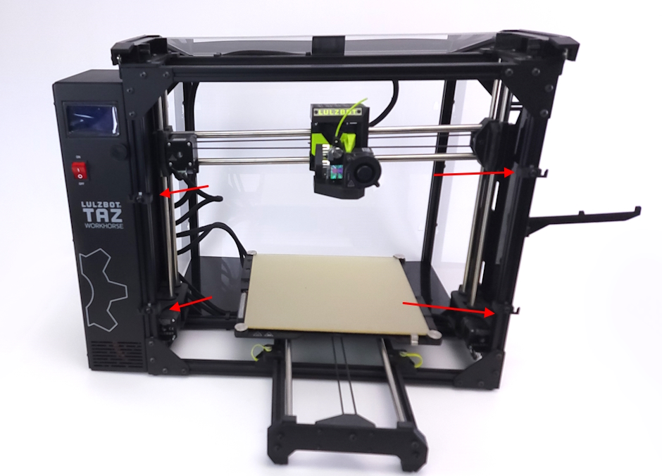
Take 3 of the screws, washers, and t-nuts and roll 2 of the nuts into the left side and 1 of the nuts into the right side of the extrusion.
Find the 3D printed panel mounts and use a screw and washer to position 2 of them so the hook protrudes on the left side of the printer and 1 protrudes to the right on the right side of the printer.
There are two different 3D prints, reference pictures for correct ones.
Repeat this on the front of the printer with 2 mounts on both the left and right sides of the printer.
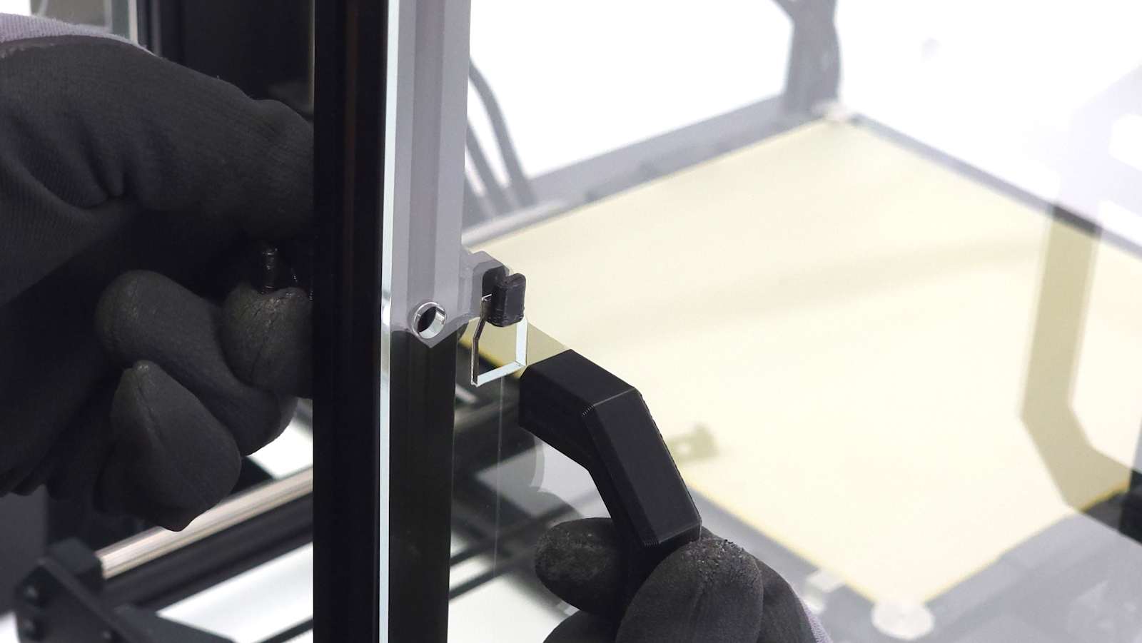
Align the back panel with the printer's frame.
With the t-nut pretty loose, slide the rear enclosure into the printer.
You will want to check the bottom panel as well as the clips will sit inside the frame and grab the printer as well.
Take your time and slowly align the top extrusions, the bottom clips, and the side panel covers.
If necessary, loosen the panel mounts to align them better before securing them.
If you are unable to slide the top extrusion into the t-nuts, you can remove the t-nuts, and slide them a little bit into the extrusion before aligning them with the top 3D printed brackets to secure.
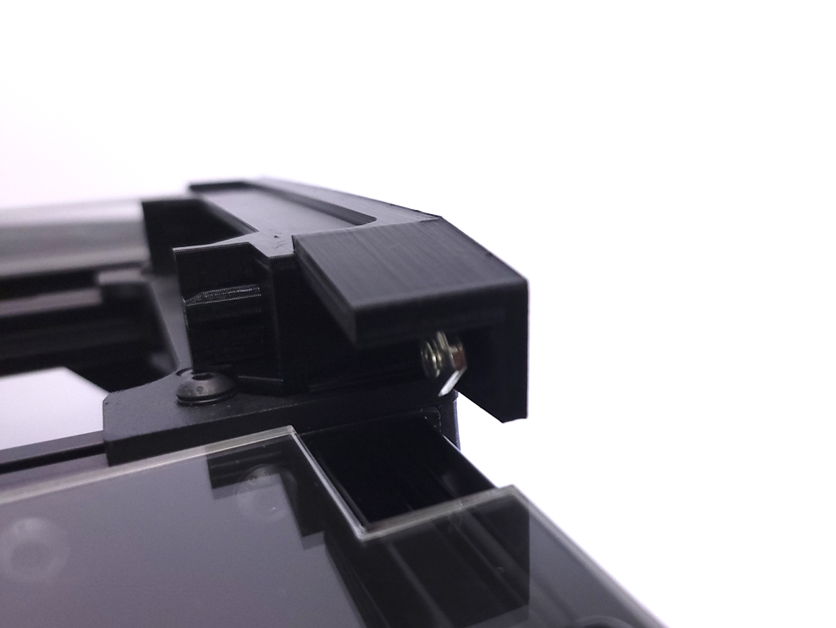
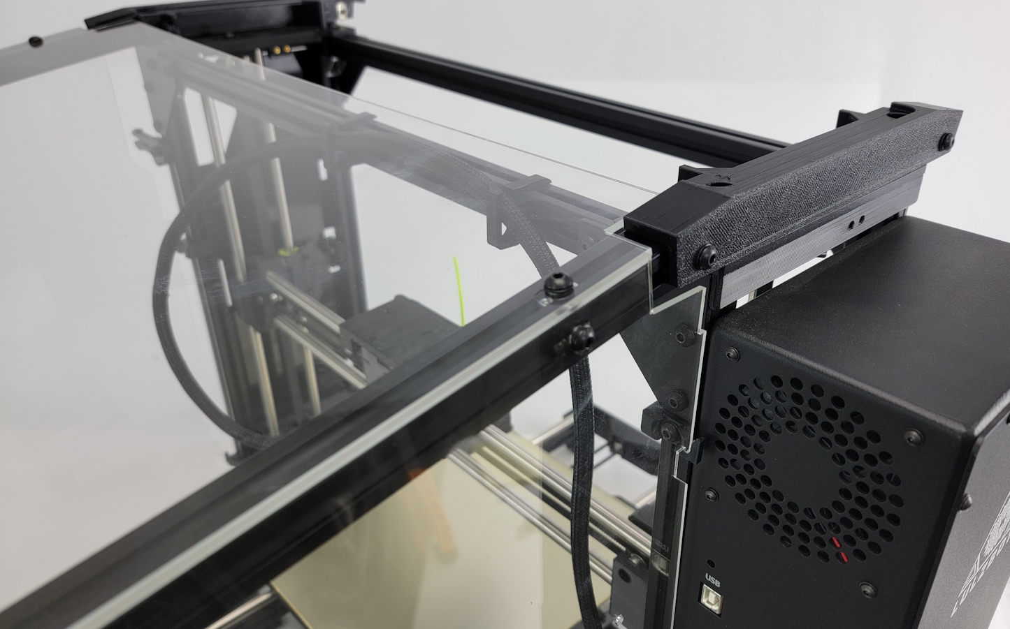
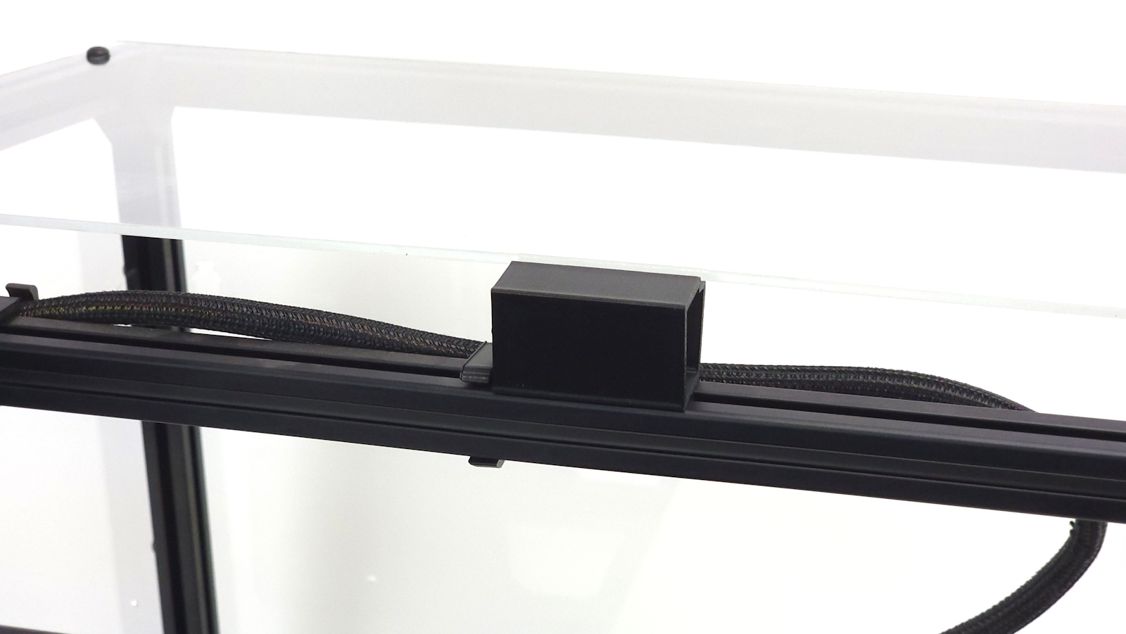
Find the 3D printed top panel brace and push it into the top extrusion to prevent the top panel from sagging.
Align the front enclosure frame with the printer's frame.
Again, with the t-nut pretty loose, slide the rear enclosure into the printer.
You will want to check the bottom panel as well as the clips will sit inside the frame and grab the printer.
Take your time and slowly align the top extrusions, the bottom clips.
If you are unable to slide the top extrusion into the t-nuts, you can remove the t-nuts, and slide them a little bit into the extrusion before aligning them with the top 3D printed brackets to secure.
Find the 3D printed top panel brace and push it into the top extrusion to prevent the top panel from sagging.
Take the side panels with the handles and place them on the side of the printer.
You will need to adjust the panel mounts attached to the printers frame to align them with the side panels.
Once the panel mounts on the printers frame have been aligned, tighten them and loosed the panel mounts on the front of the enclosure.
Align these with the side panels.
Once the side panels have been aligned, the front panel should also be aligned.
Install all 3 panels with handles to ensure fitment, if necessary, adjust the mount positions so each panel attaches securely and will not fall off.
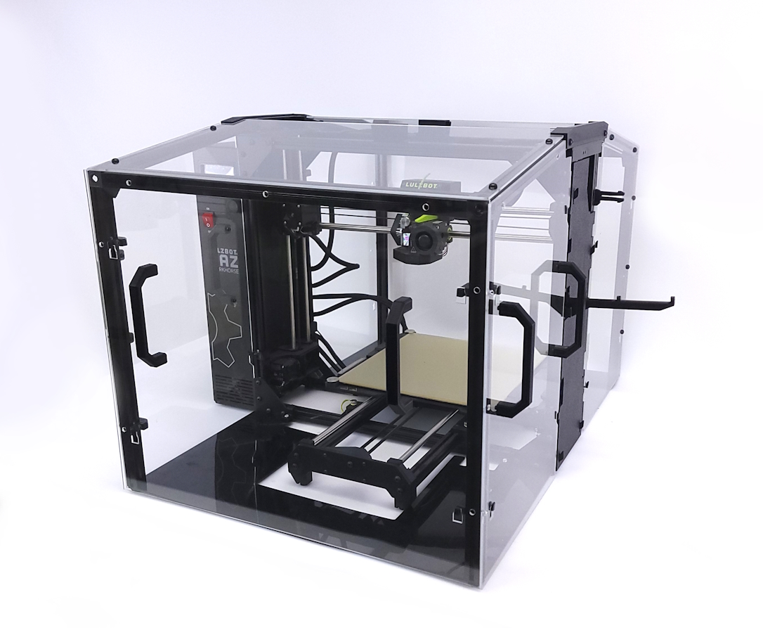
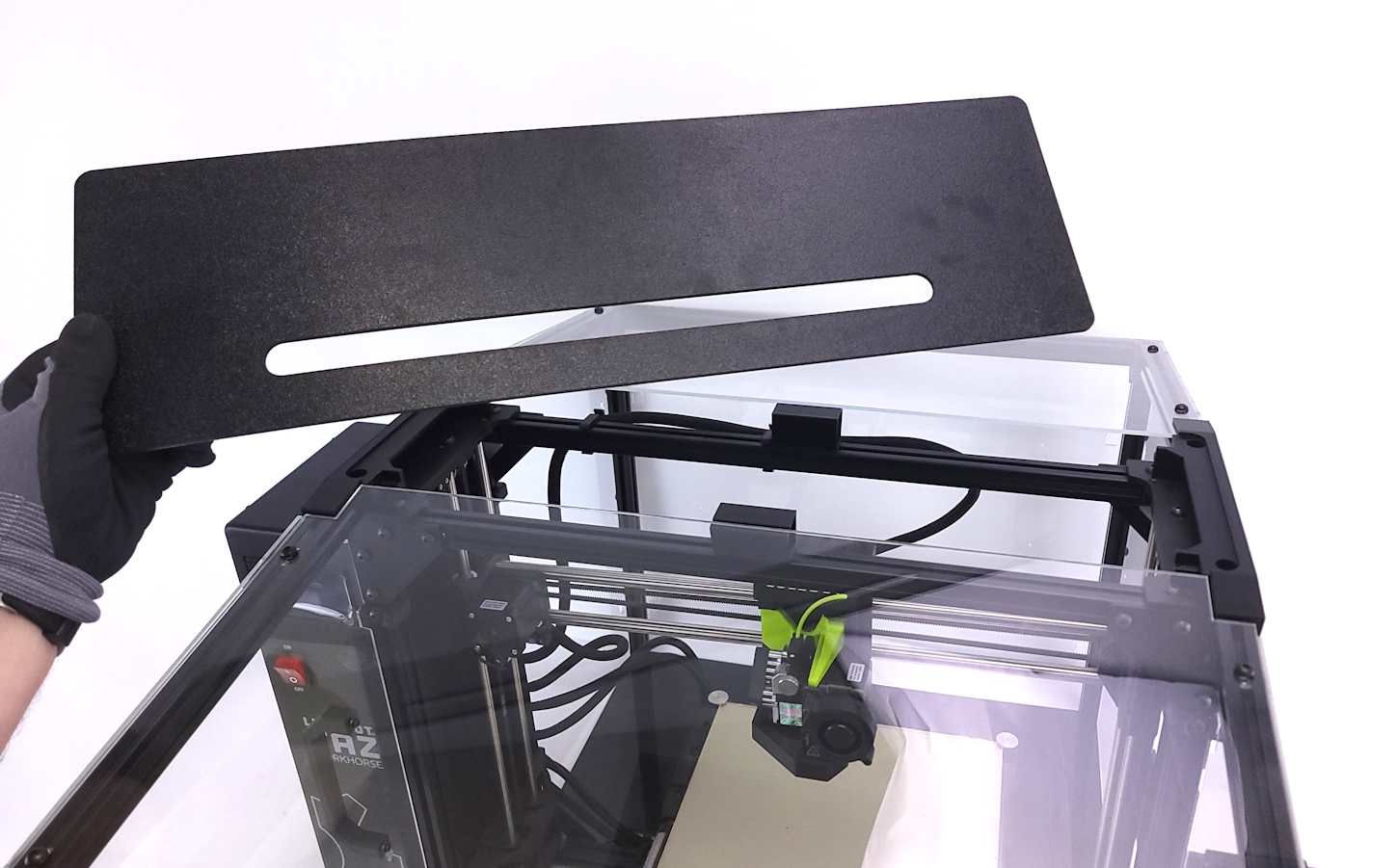
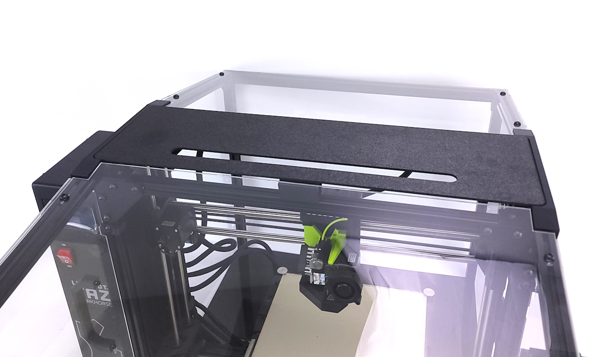
Locate the top black panel and place it on the top of the printer.
It will fit into the printed top brackets and just sit in place.
The slot for the filament should sit closer to the front of the printer.
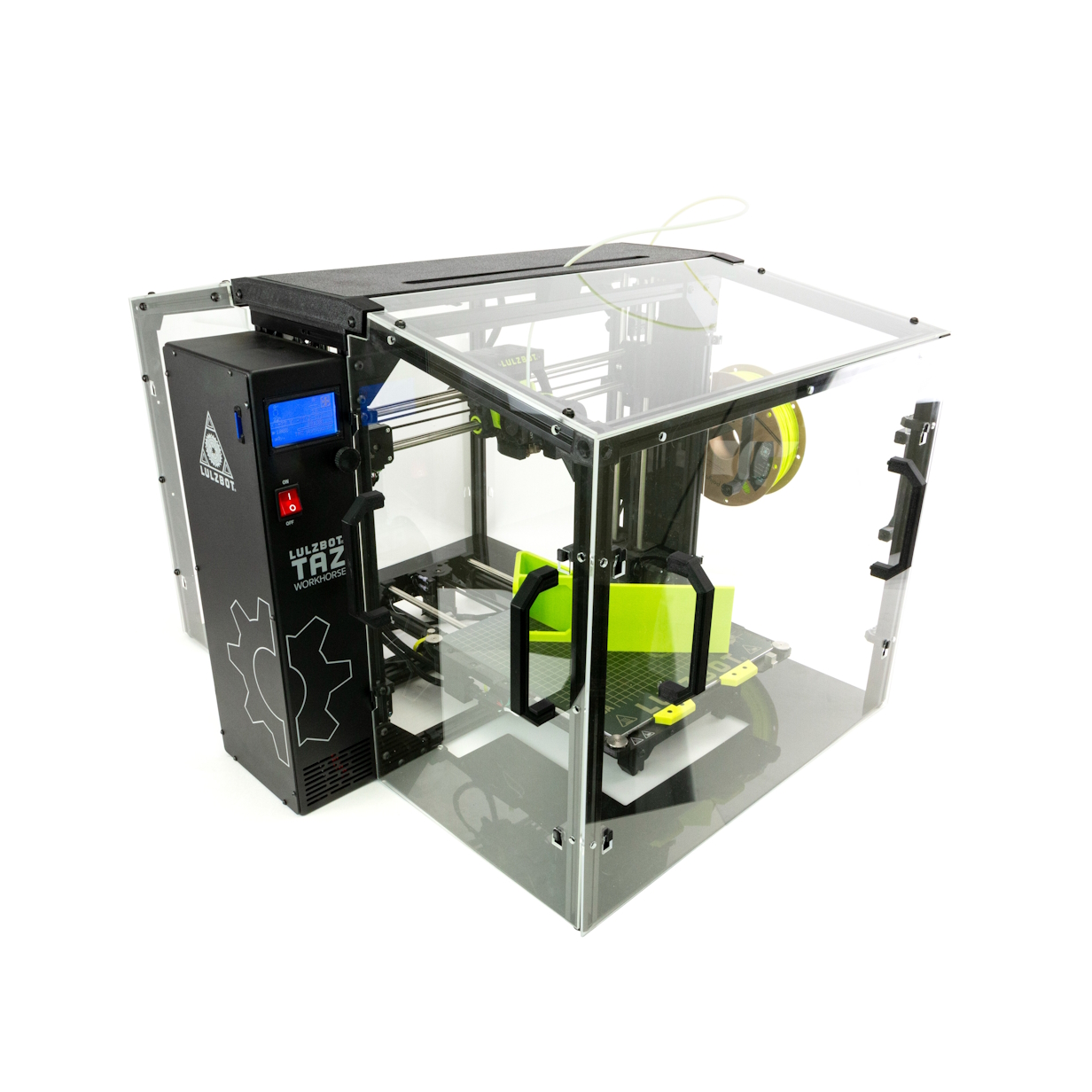
Congratulations! Your enclosure is assembled and ready to use!
If you encounter issues please contact Technical Support by emailing support@LulzBot.com, or by calling +1-701-809-0800.