Open HardwareAssembly Instructions
Guides for installation and assembly of the LulzBot line of products made by FAME 3D LLC.
Guides for installation and assembly of the LulzBot line of products made by FAME 3D LLC.
The LulzBot TAZ SideKick Filament Runout Sensor will catch the moment your print runs out of filament during a 3D print. This option will stop your print automatically until you can return to add more filament.
We recommend removing the Y-Axis to provide better accessibility during the installation, however you are able to install the Filament Runout Sensor with the Y-Axis installed. You may need to move the bed plate around in order to route the sensor wire through the printer.
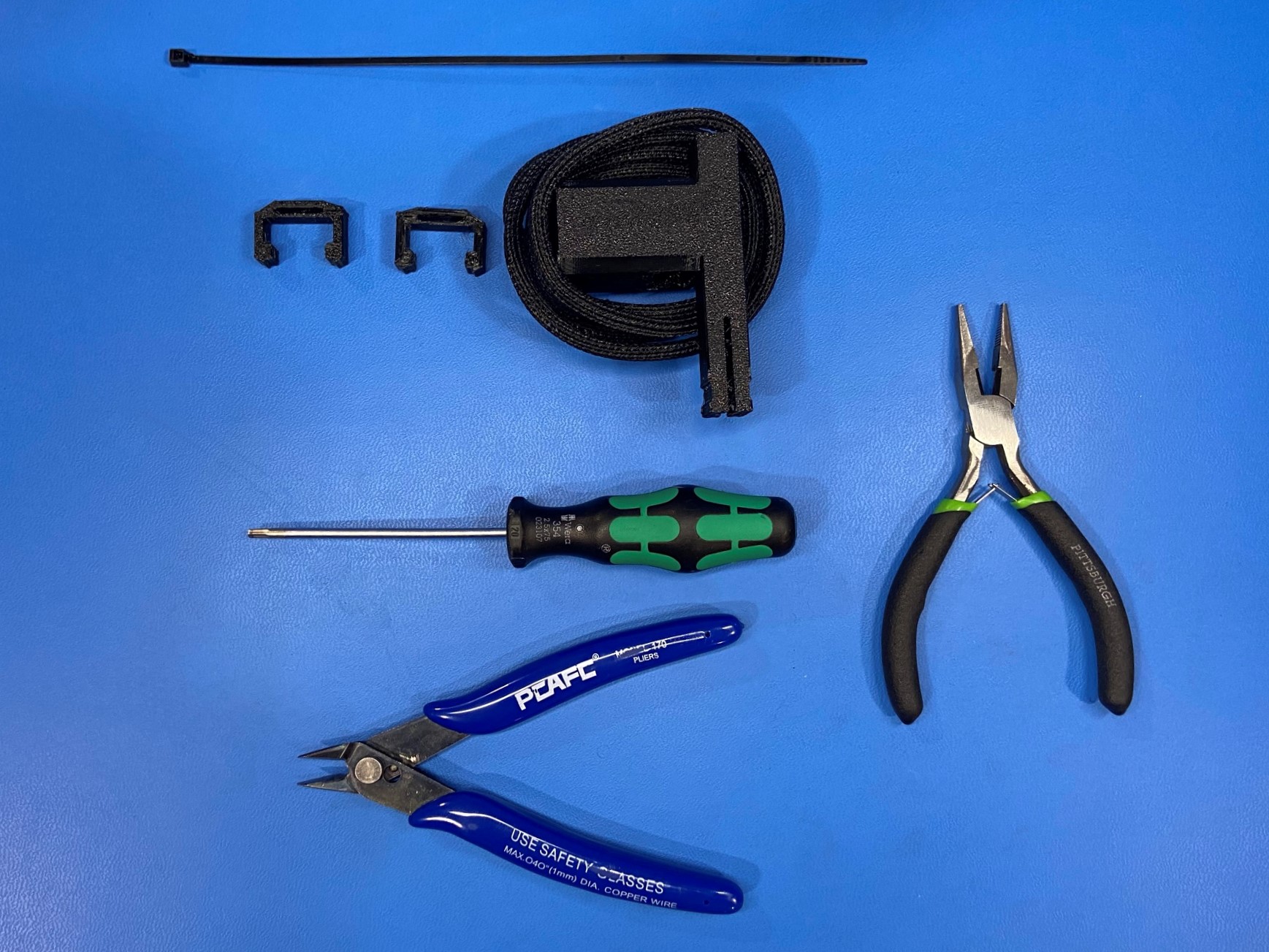
The items required for the installation of the TAZ SideKick Filament Runout Sensor:
Before starting, power off and unplug your TAZ SideKick.
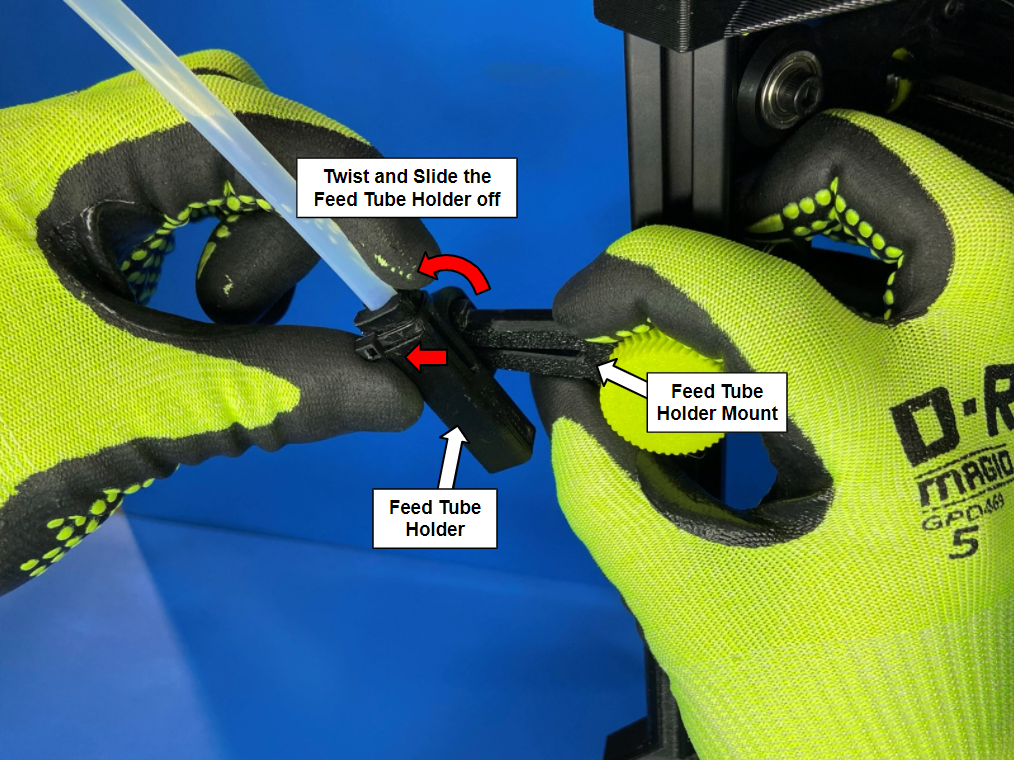
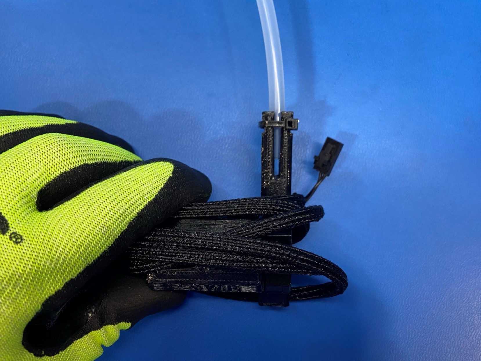
Now start by sliding the feed tube holder to the end of the feed tube holder mount.
Then pinch the middle of the mount so that there is little to no gap at the end of the mount.
Now twist the feed tube holder so that the top side slides over the top tab on the feed tube holder mount, then you are able to completely slide the feed tube holder off of the feed tube holder mount.
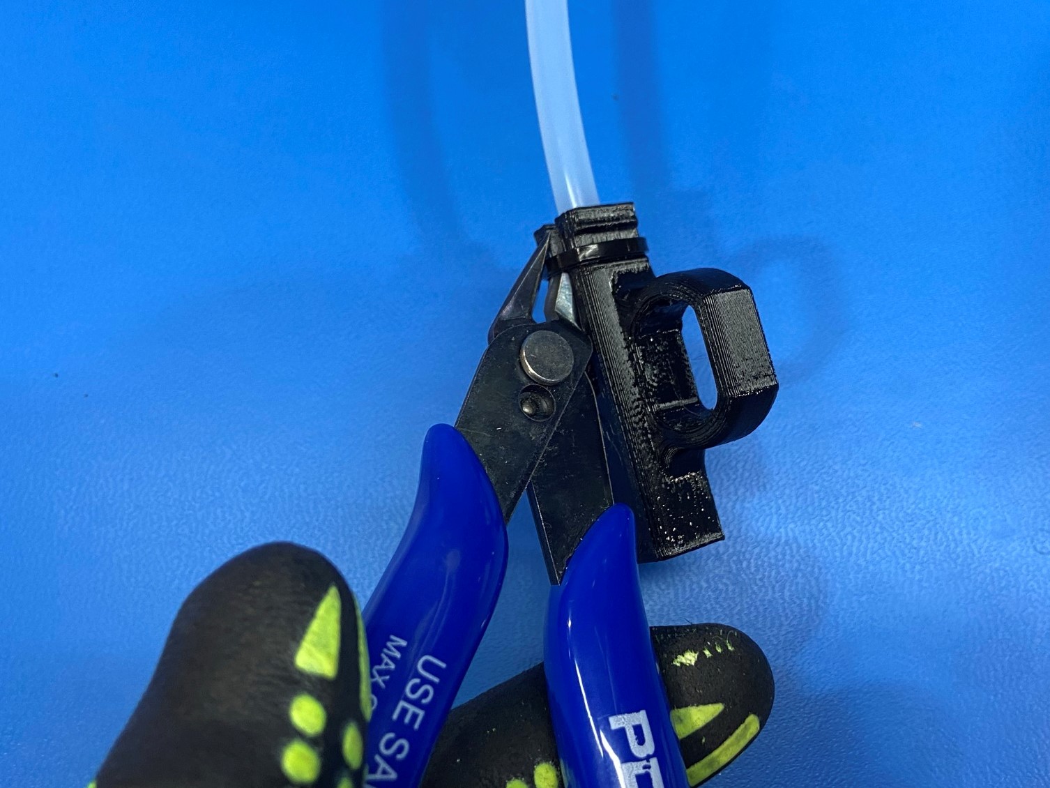
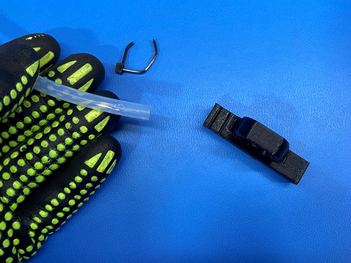
Using the slide cutters or scissors, cut the cable tie that is holding the feed tube in place. We will be using the feed tube for the filament runout sensor.
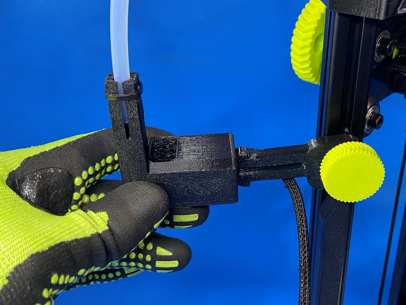
Then slide the feed tube inside the filament sensor and secure using the 8" cable tie provided in the SideKick Filament Runout Sensor kit.
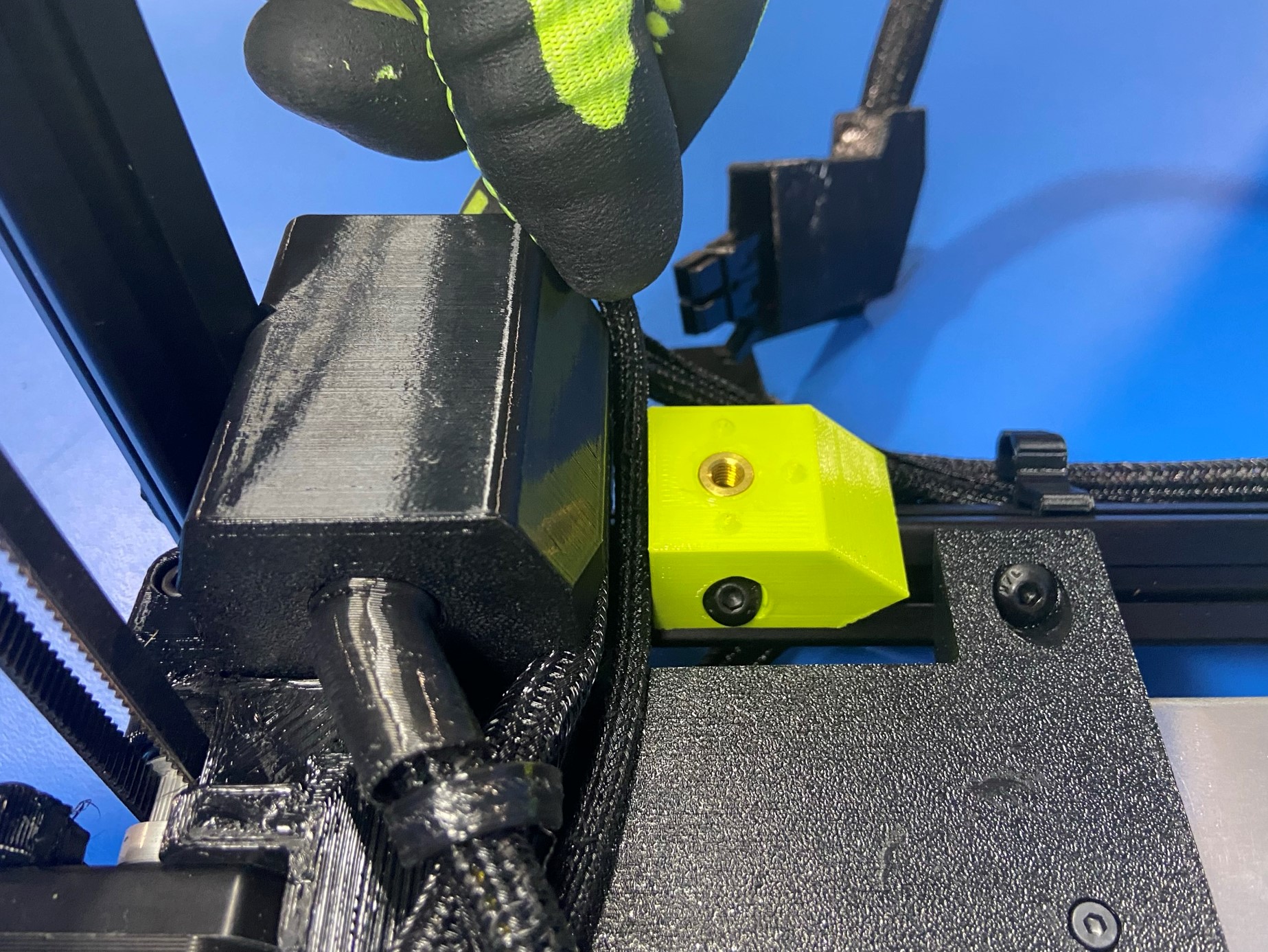
Take the runout sensor and slide it onto the feed tube holder mount making sure the feed tube is on the top side.
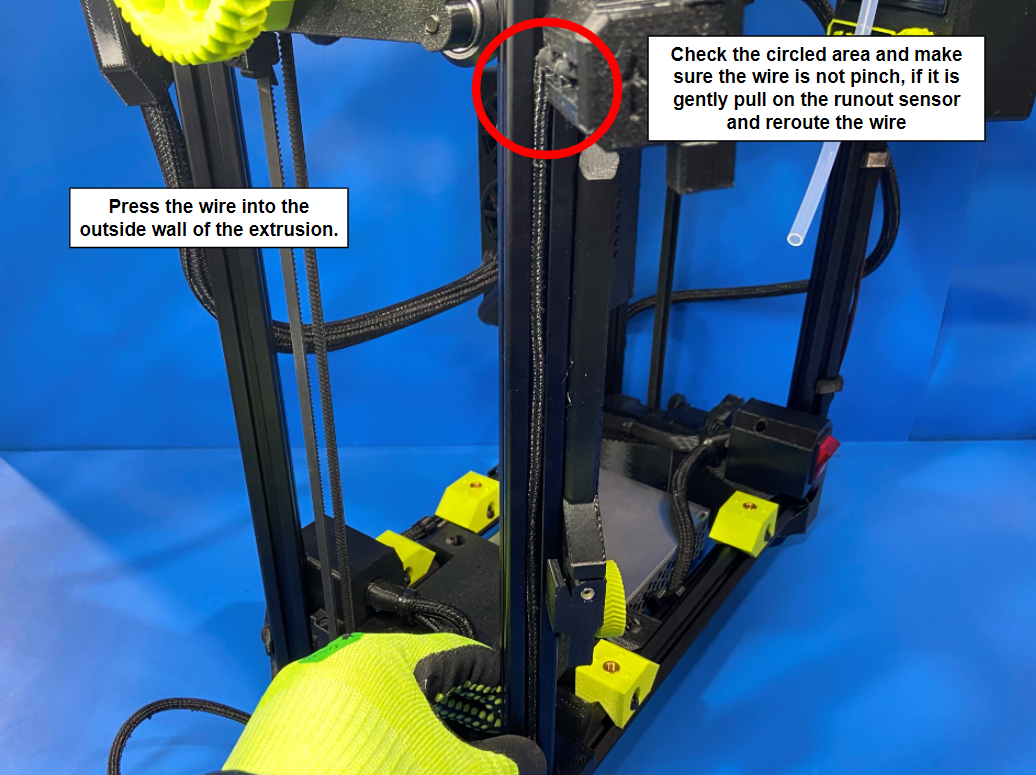
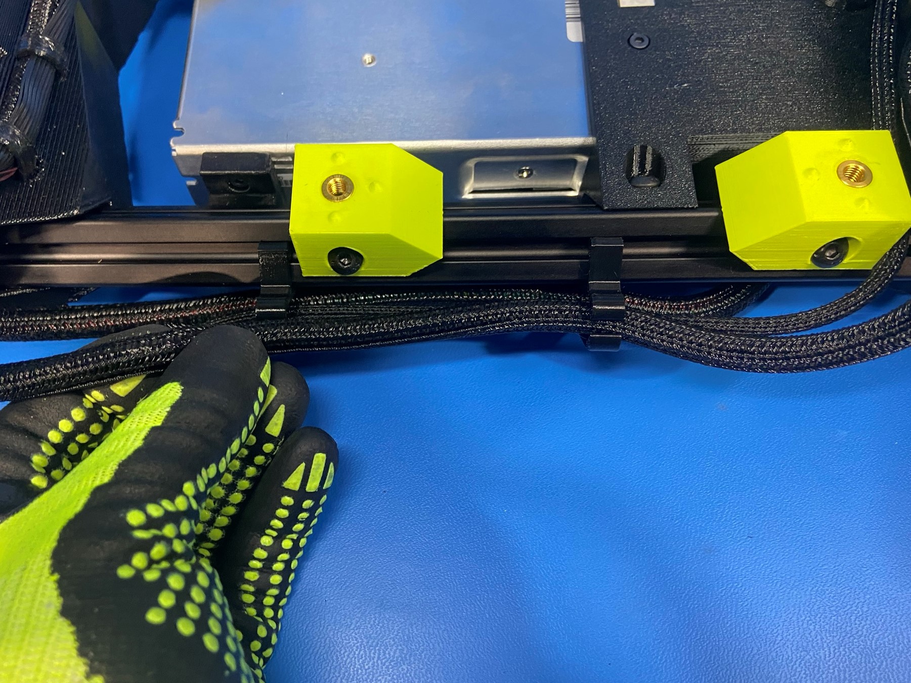
Then press the wire into the extrusion, then check by the runout sensor to make sure the wire is not pinched by the plastic.
Now secure the wire to the extrusion with the provided LCD Cable Clips.
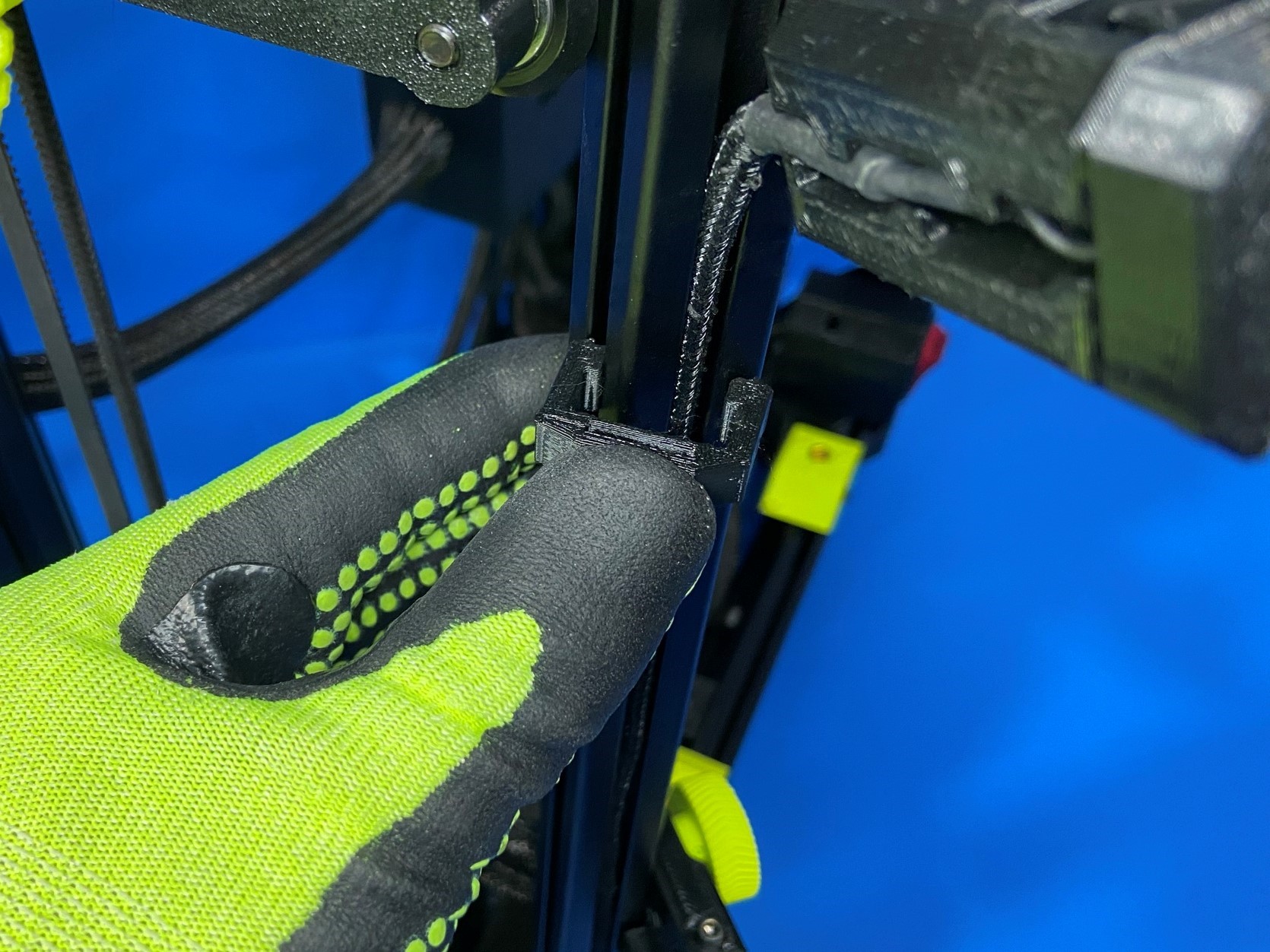
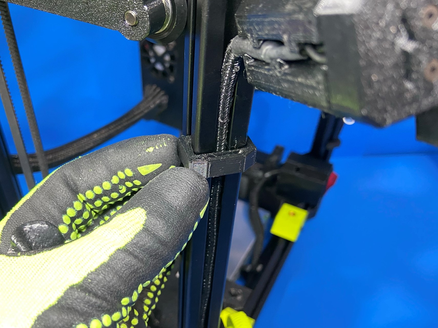
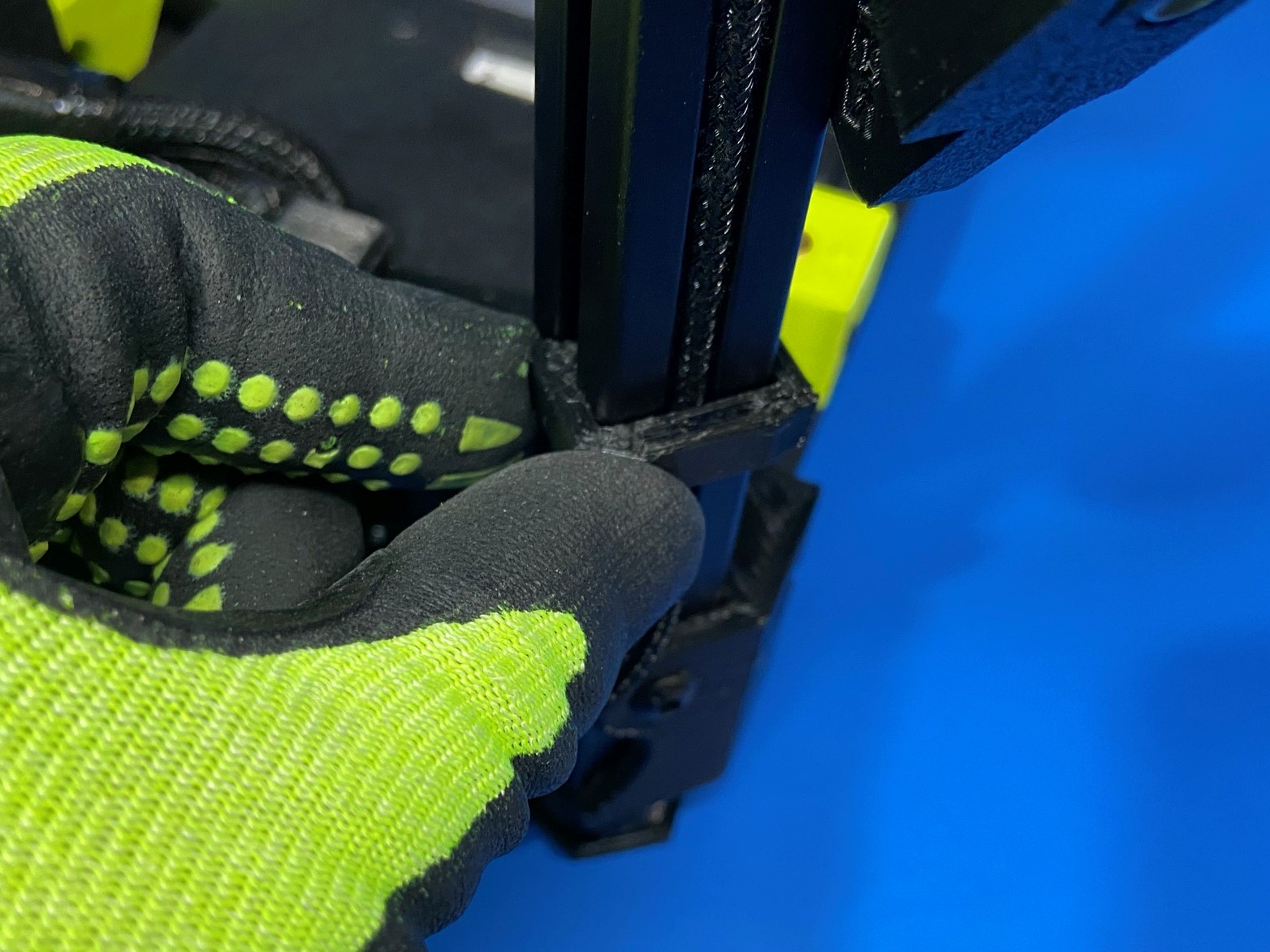
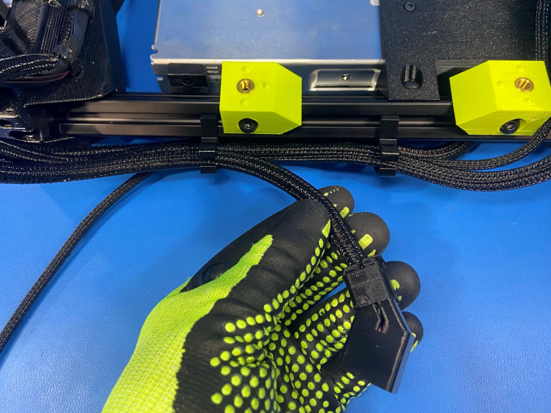
Take the wire connector and feed it in between the extrusion and the left Z axis motor.
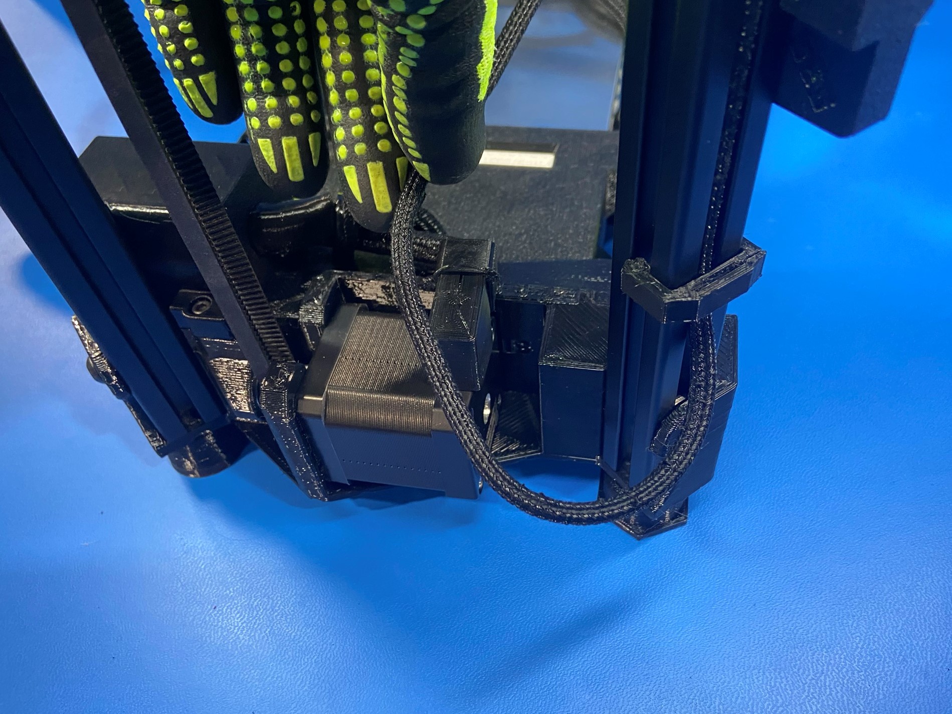
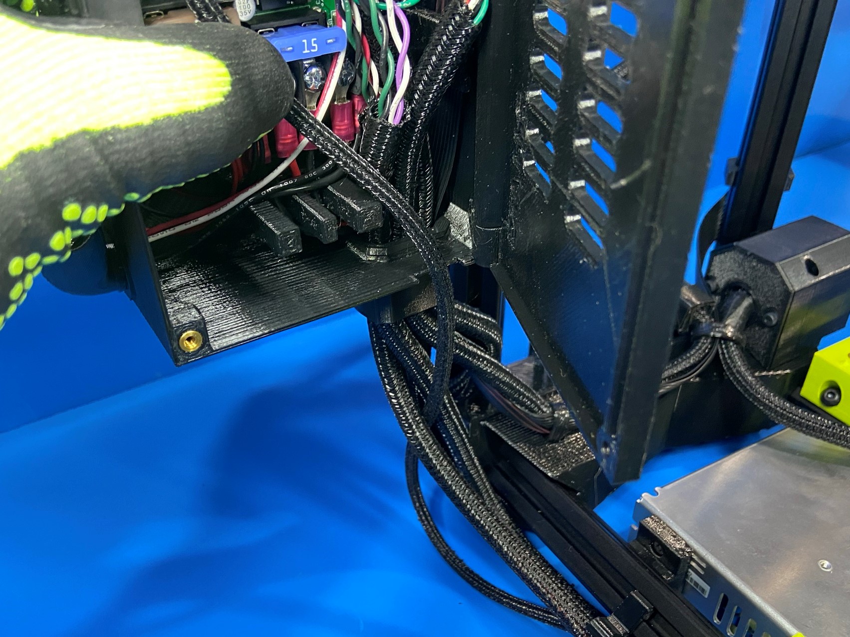
Then route the wire under the wire harness that goes into the power supply as shown in Reference#1, you may need to move the LZ motor harness around in order to route the runout sensor wire under the power supply harness.
The TAZ SideKick 747 printer will have a larger gap then the TAZ SideKick 289 printer.
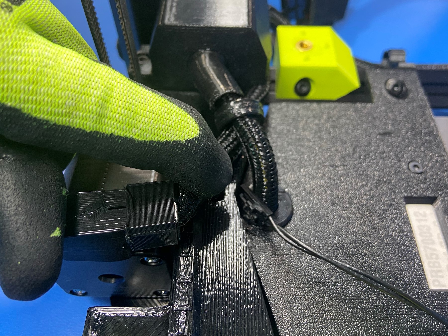
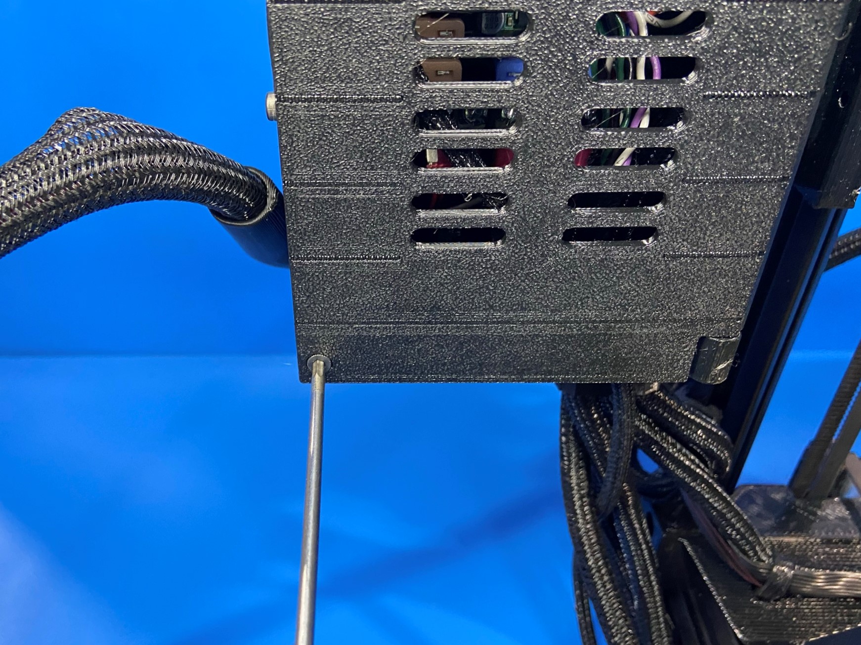
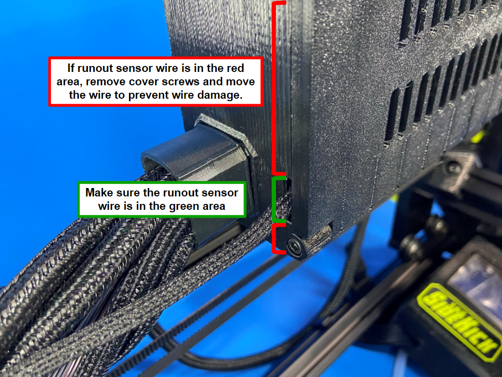
Now take the wire and slide it between the Y-Axis frame mount and the power plug housing, making sure the wire is secured by the power supply harness and is tucked away from any moving component.
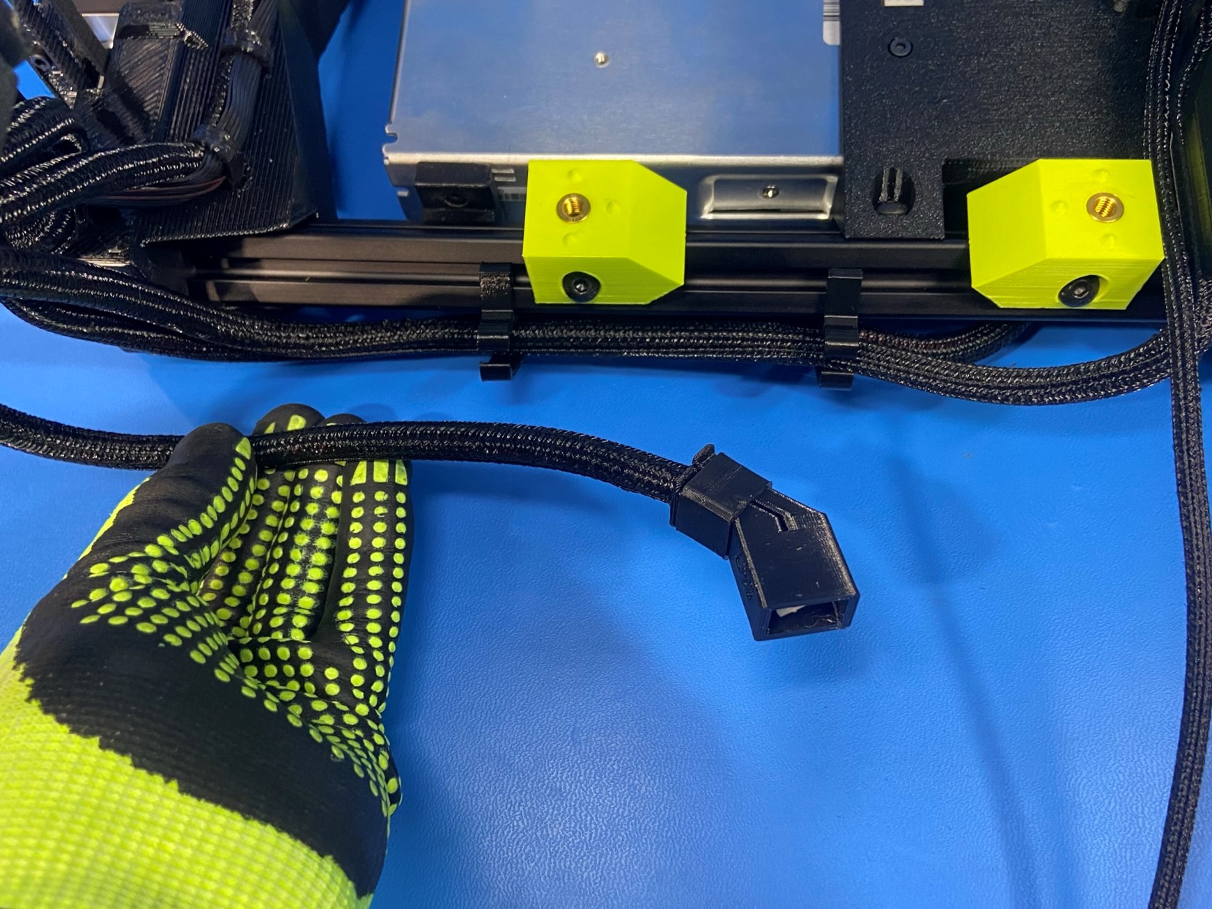
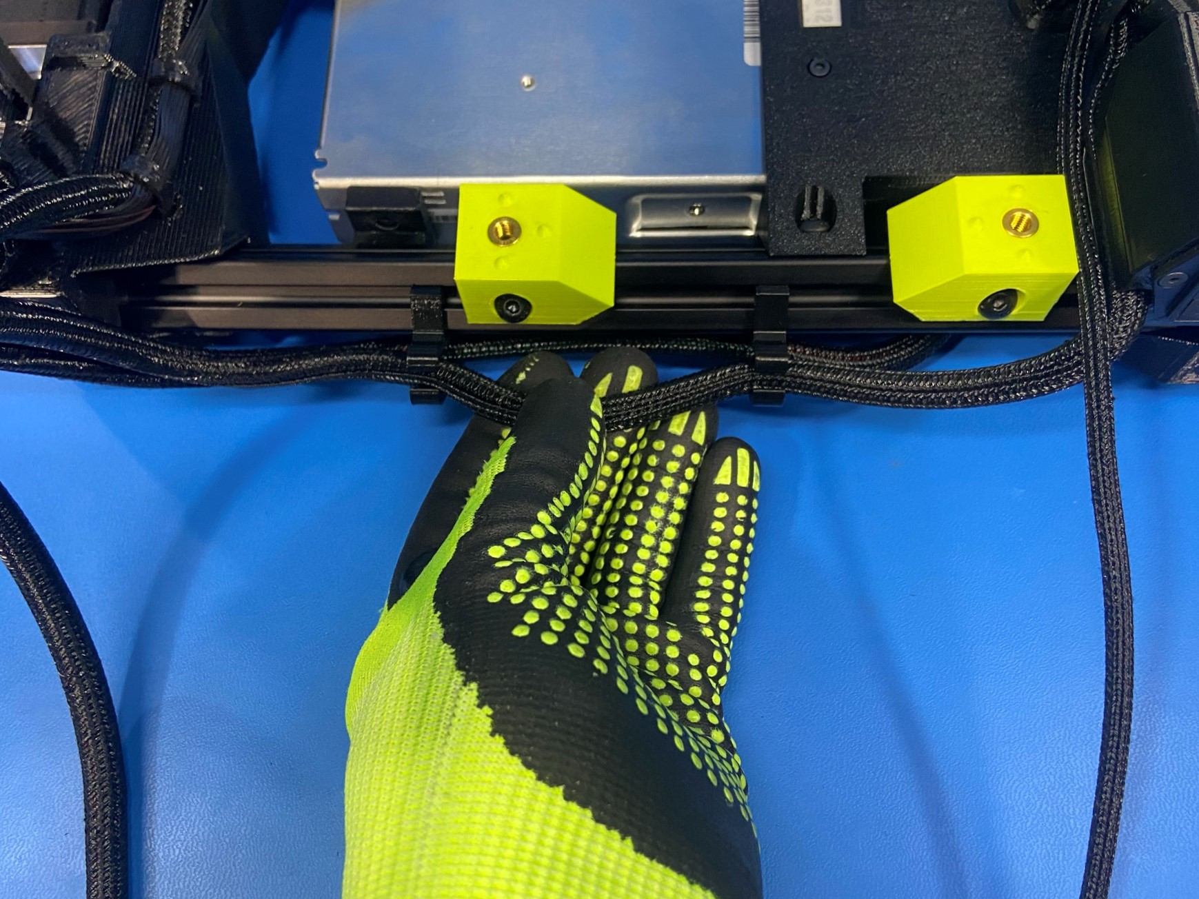
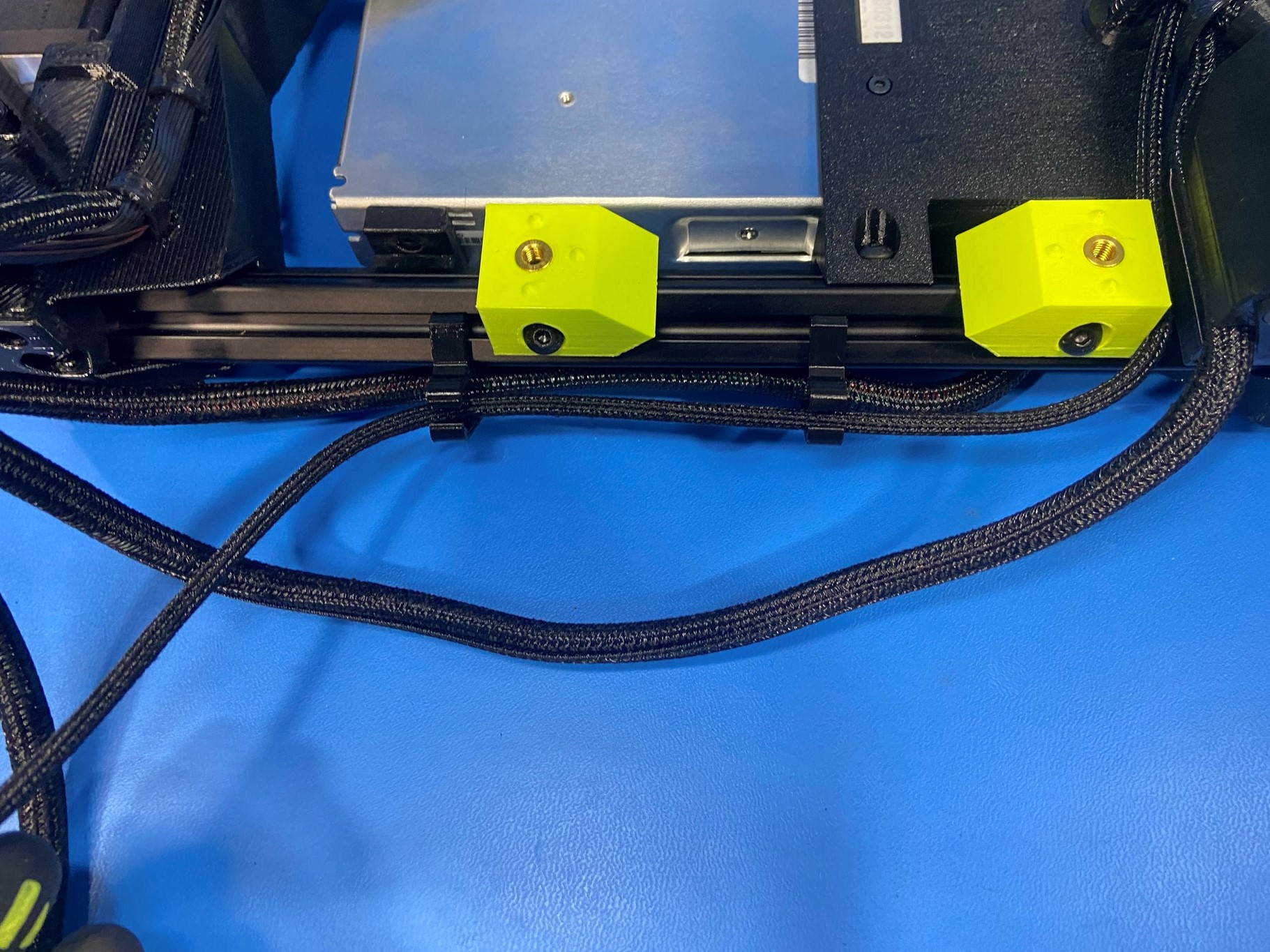
Remove the Y and LZ motor harnesses from the cable clips and then place the runout sensor wire inside the cable clips.
Once the runout sensor wire is secured in the cable clips place the LZ motor harness back in the cable clips, followed by the Y motor harness.
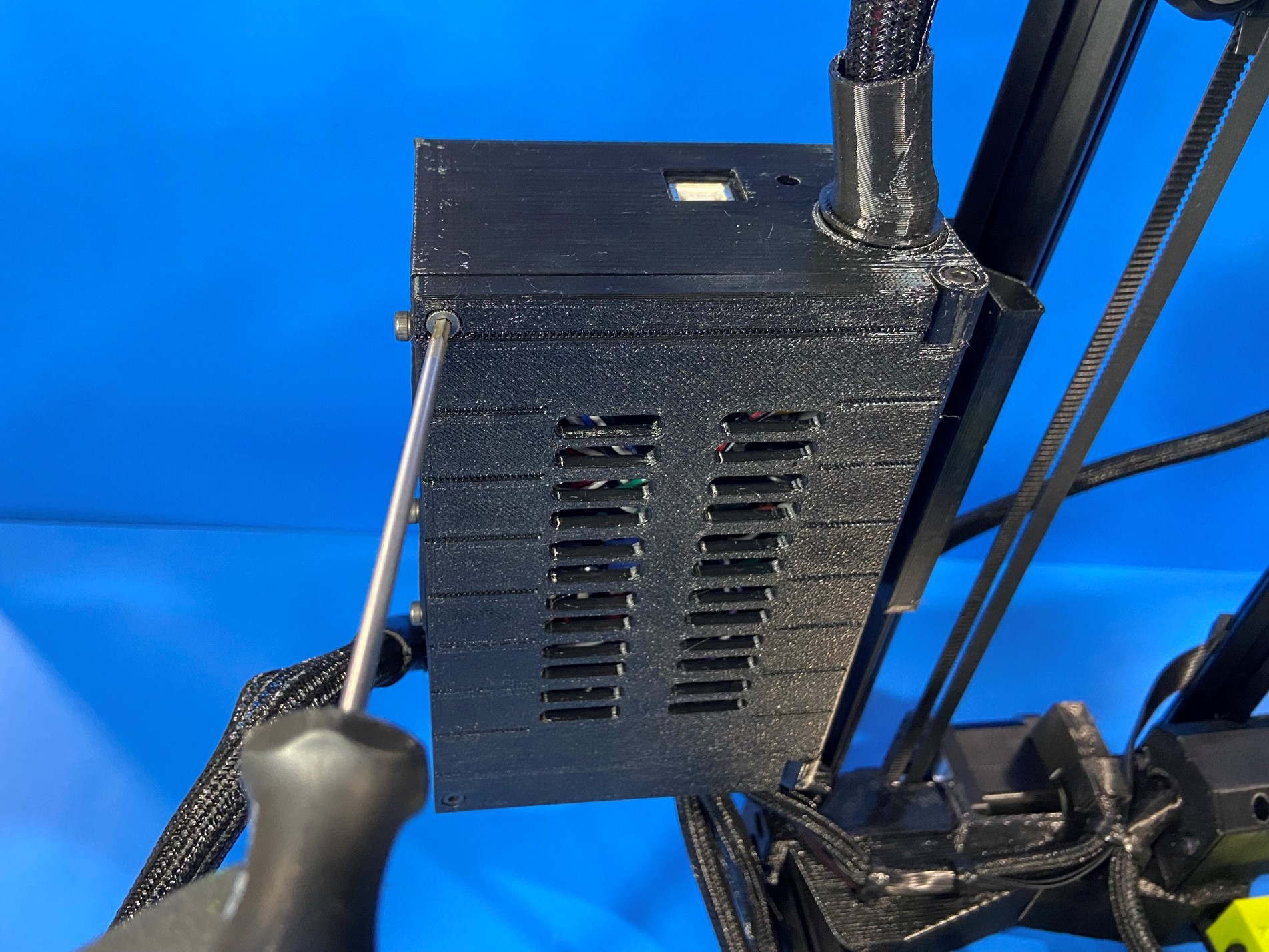
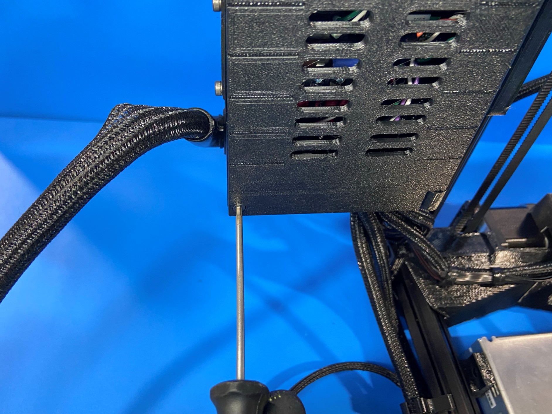
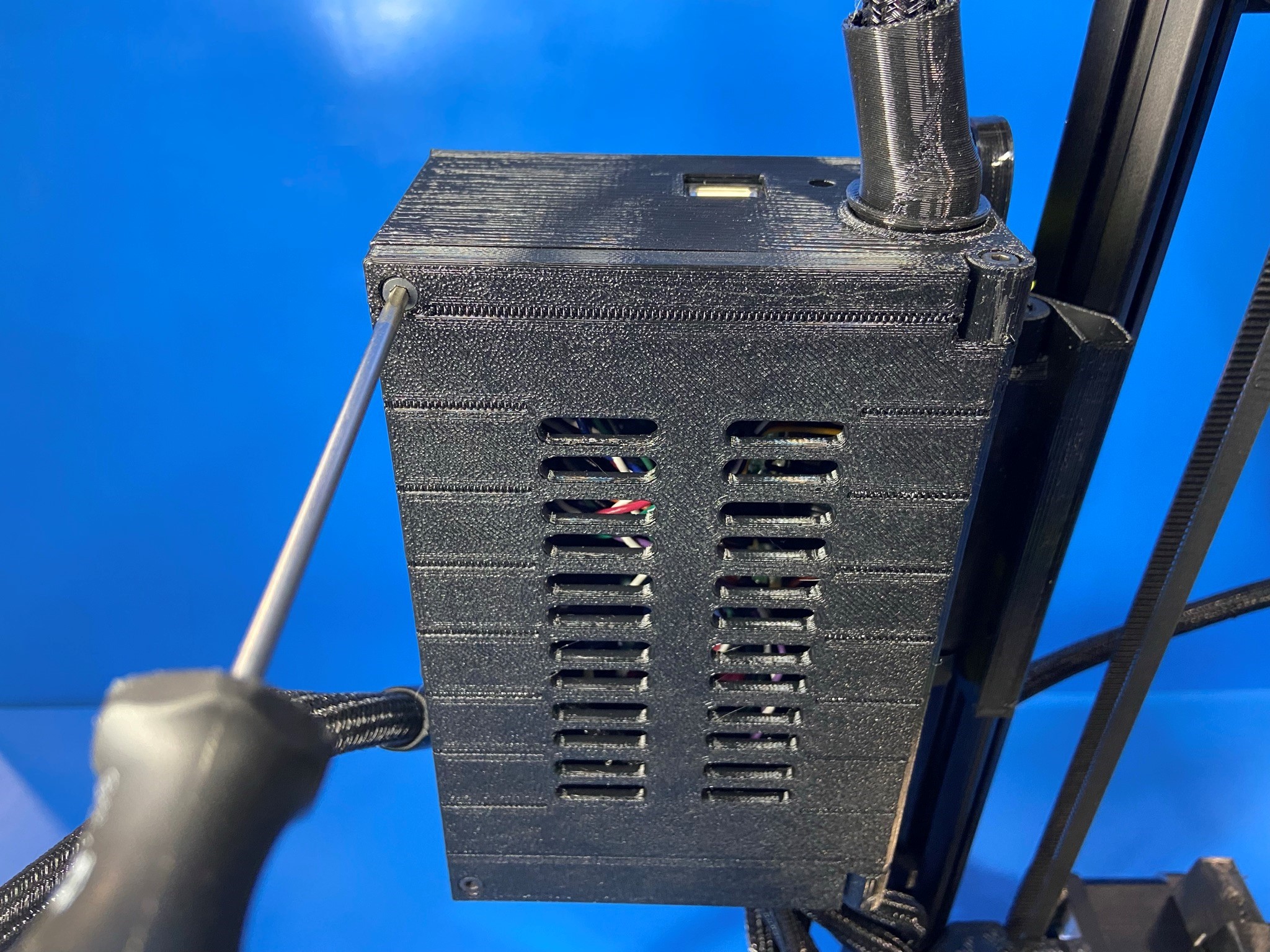
Use the 2.5mm hex driver and remove the two bolts that are holding the control box cover in place, keep track of these two bolts because you will need them to close the box.
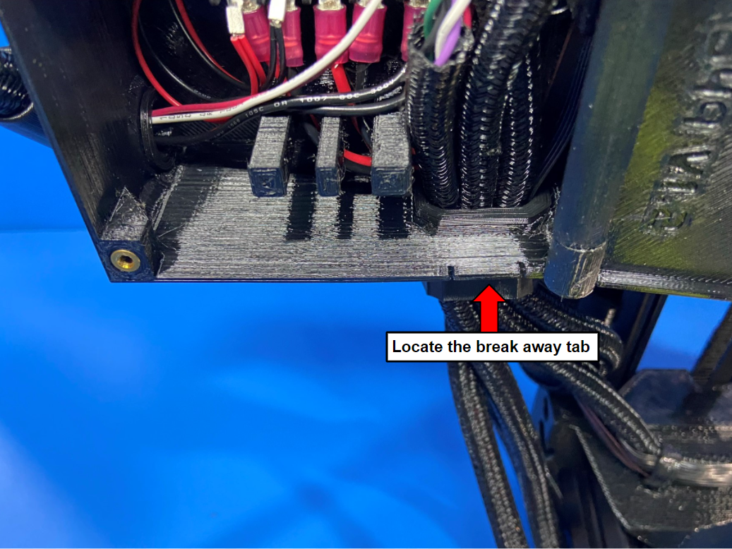
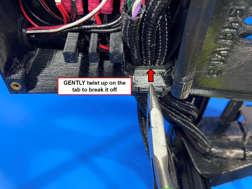
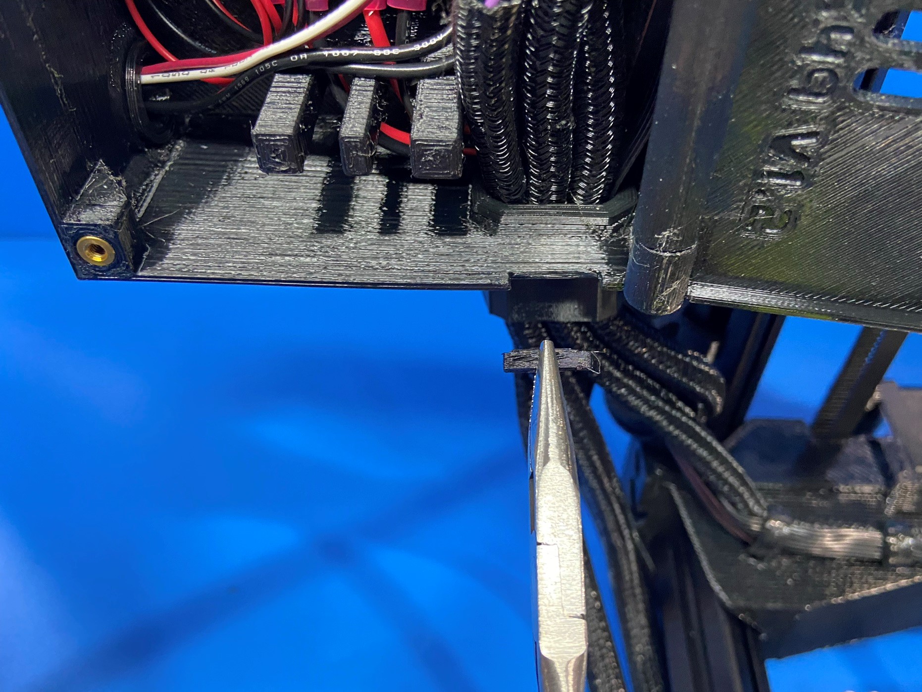
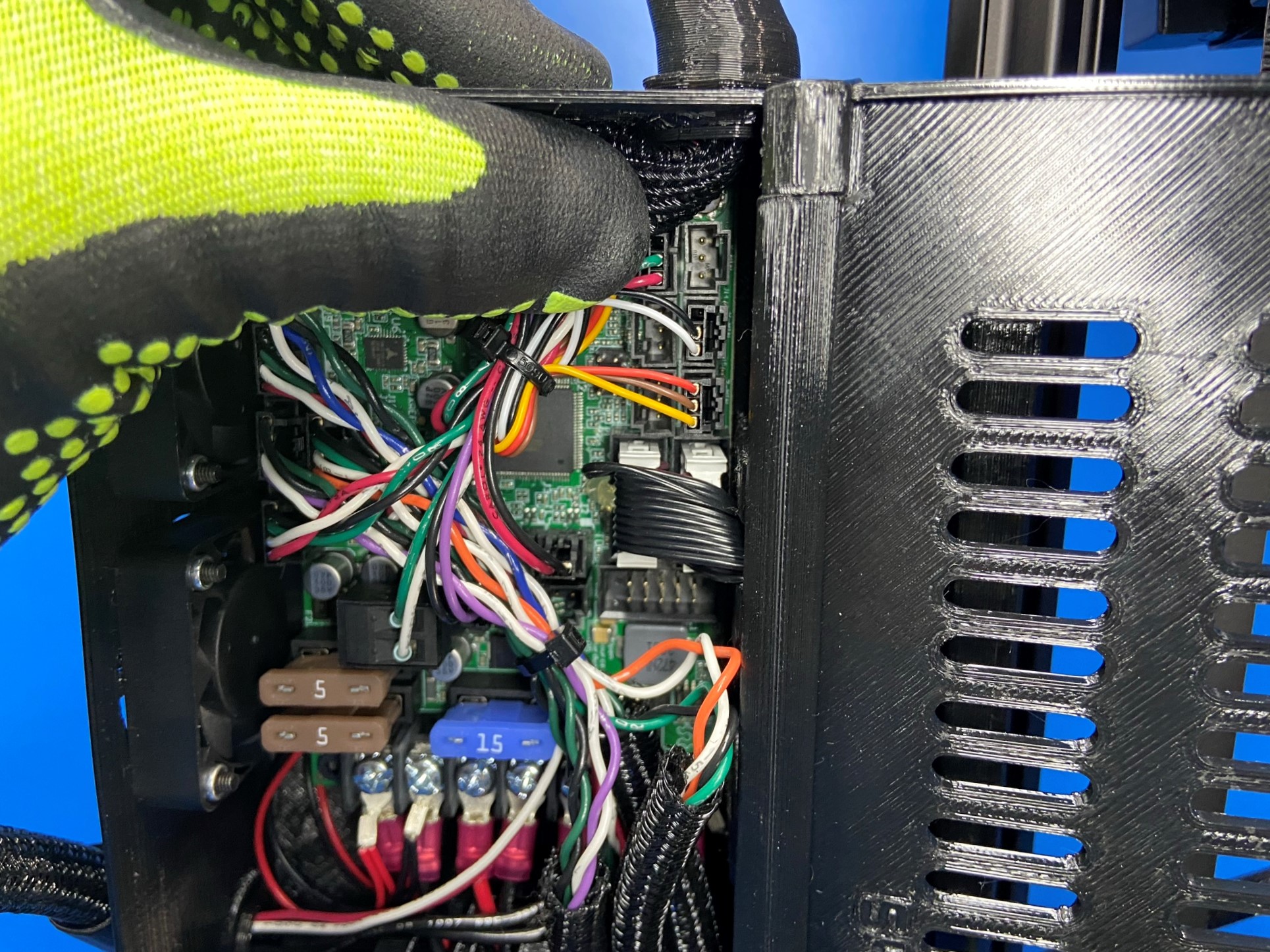
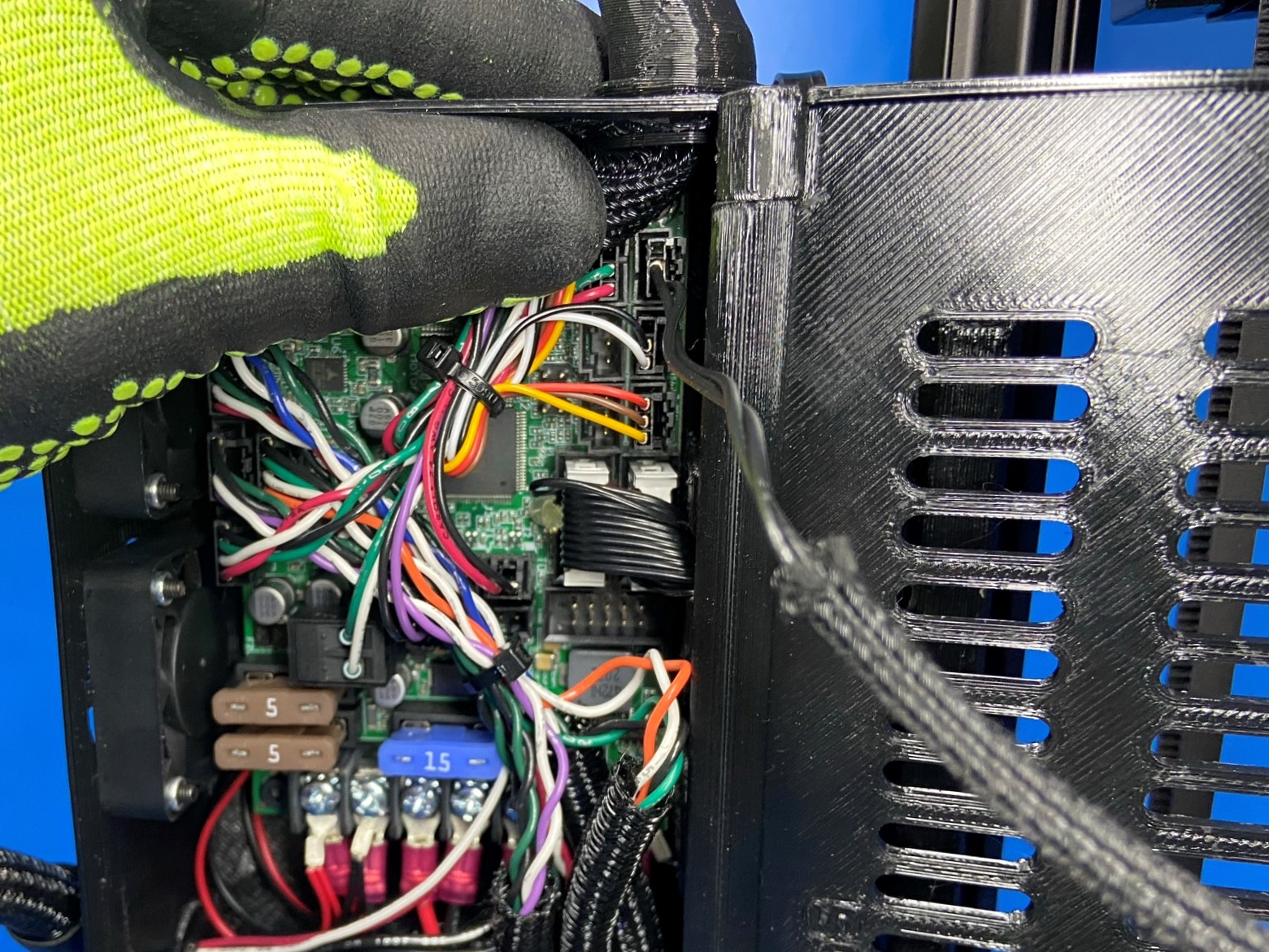
Using a small pliers or tweezers gently twist up on the breakaway tab on the control box. Make sure to GENTLY twist to prevent breaking off more of the wall
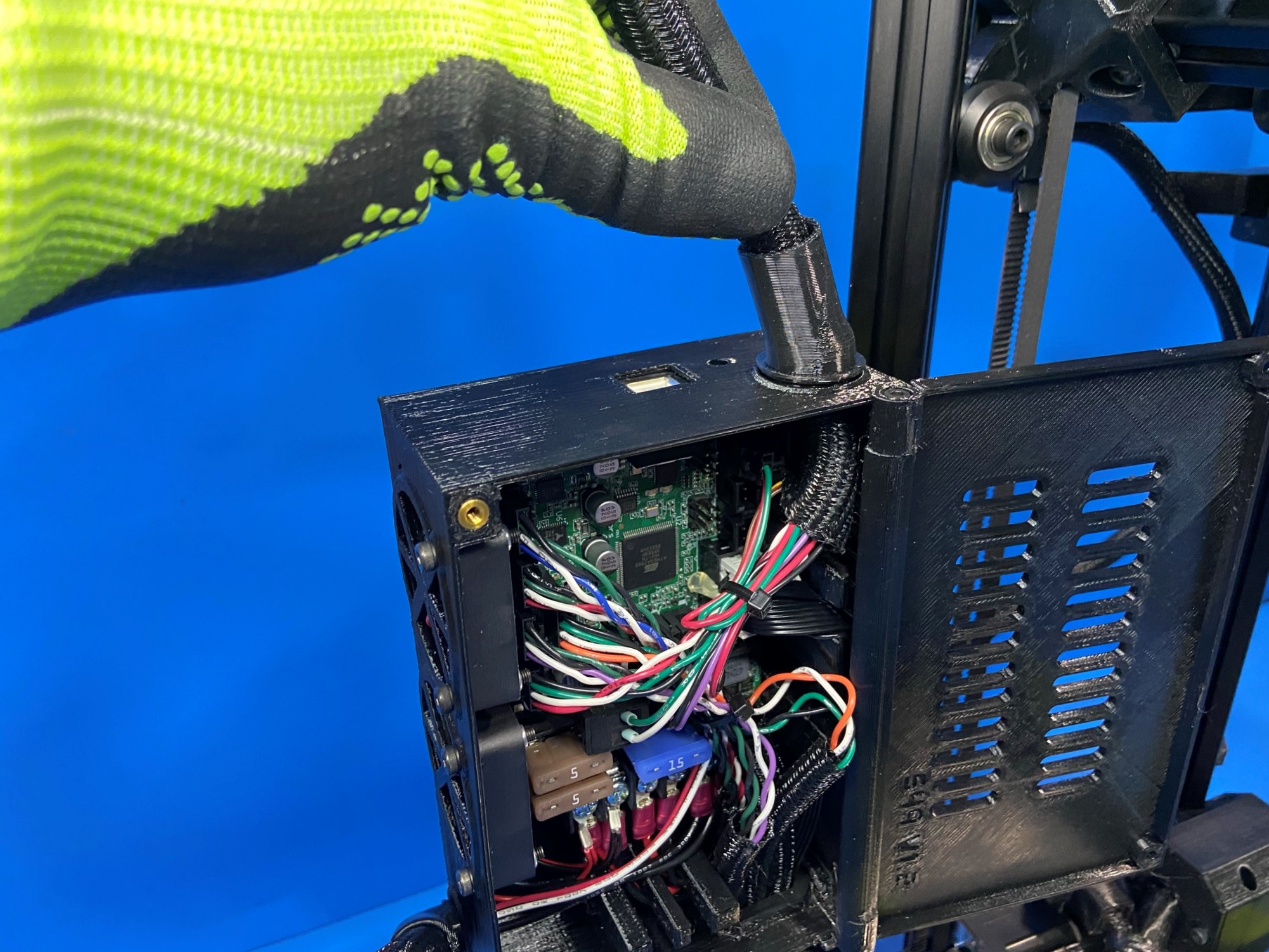
Then push the extruder harness into the board so you are able to connect the runout sensor wire to the board.
Now take the connector at the end of the runout sensor wire and have the mostly flat side face the control box fans then connect the wire to the top right port.
Use the 2.5mm hex driver to replace the two bolts that close the control box.
Once the control box has been screw shut, plug your printer in and turn it on. You are ready to print with your newly installed LulzBot TAZ SideKick Filament Runout Sensor!