Open HardwareAssembly Instructions
Guides for installation and assembly of the LulzBot line of products made by FAME 3D LLC.
Guides for installation and assembly of the LulzBot line of products made by FAME 3D LLC.
Failure to complete each step may result in unwarrantable damage to printer and its accessories.
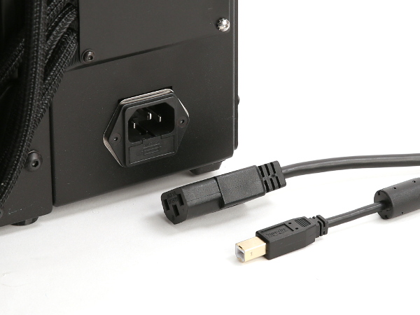
Unplug the AC power cable from the wall outlet, then unplug from the rear of the printer.
Unplug the USB cable (if installed).
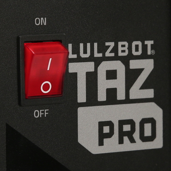
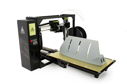
Make sure you LulzBot TAZ Pro S is turned off and unplugged.
Materials Needed


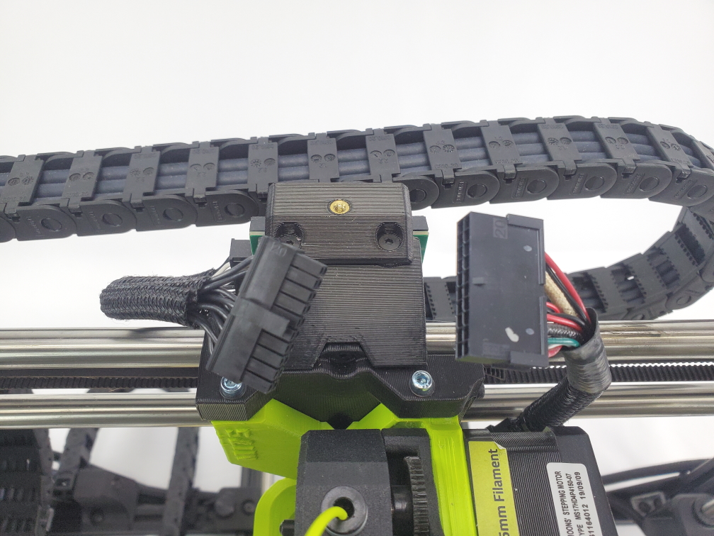
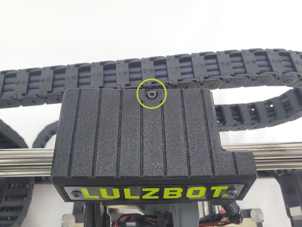
Unscrew the single screw highlighted on the top of the tool head cover.
Lift the toolhead cover up and off of the tool head.

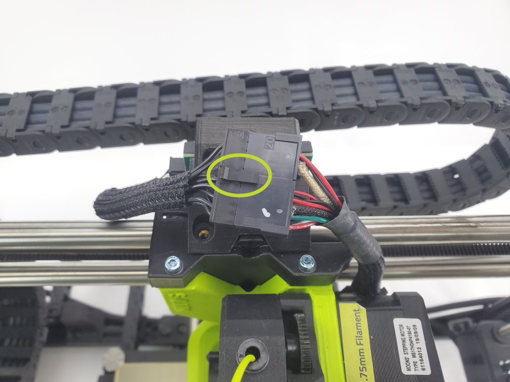
Depress the retaining tab on the connector housing and gently wiggle the connector free.
Do not pull on the wires, only the connector housing.
The tool head is attached with three screws. The print surface can be damaged if the tool head is allowed to fall onto the print surface. With one hand, support the tool head while following removal steps below.
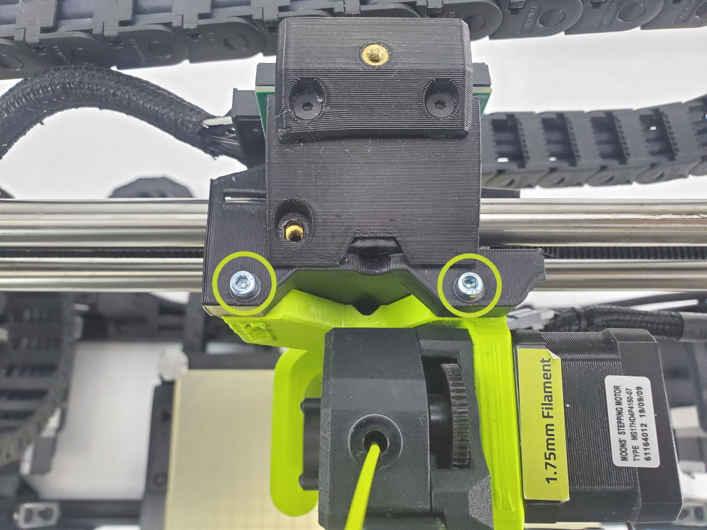
Using the 2.5mm hex key, unscrew the three M3 screws securing the tool head to the X-axis carriage. Remove the rear screw first, followed by the remaining top two screws.
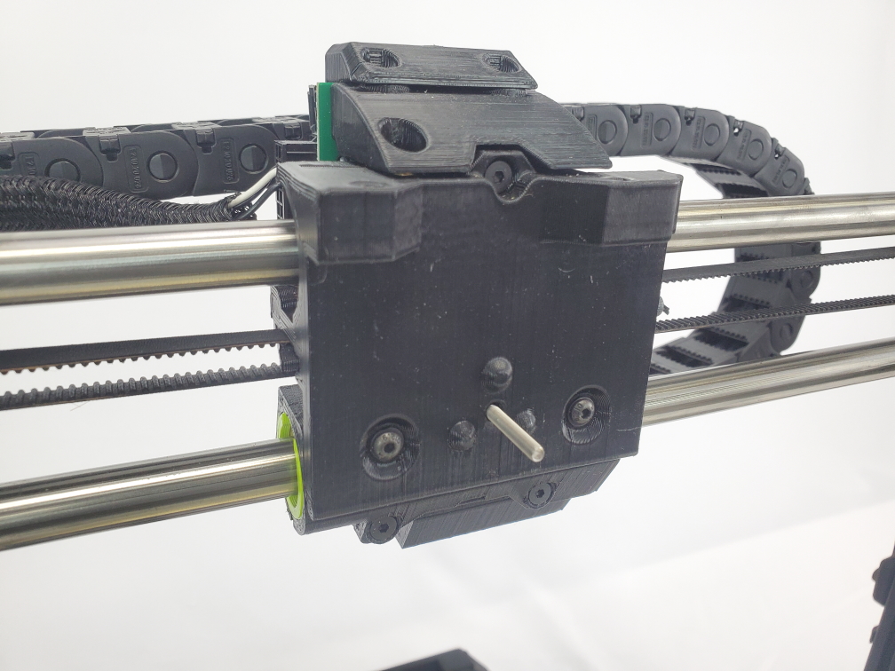
Remove the tool head from the printer by moving the tool head away from the printer.

Locate the bag of hardware that came with the BLTouch and remove the long screw from the bag of hardware. Transfer the washer from the rear screw on the Pro S onto the new, longer screw that you will be installing.
Align the BL Touch adaptor mount with the X carriage making sure the brass inserts align with the holes on the X carriage.
Push the longer screw and washer through the rear hole to secure the BL Touch adaptor mount to the X carriage.
Using the previously removed tool head mounting screws, insert them into the top two holes and secure them through the carriage and into the BLTouch mounting plate.
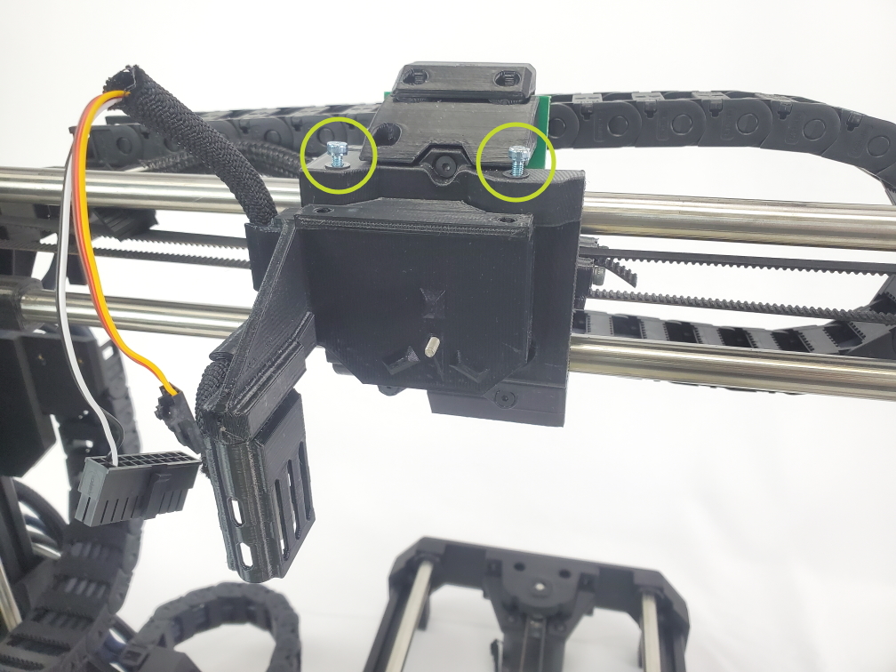
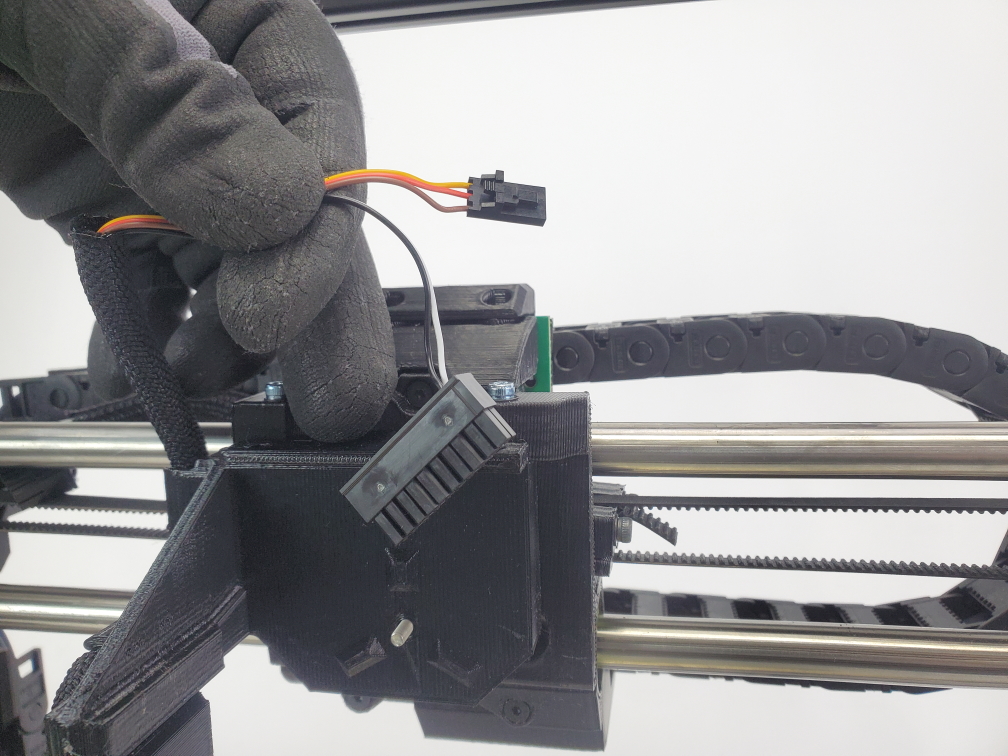
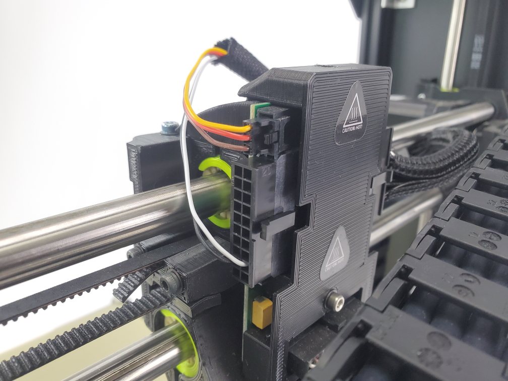
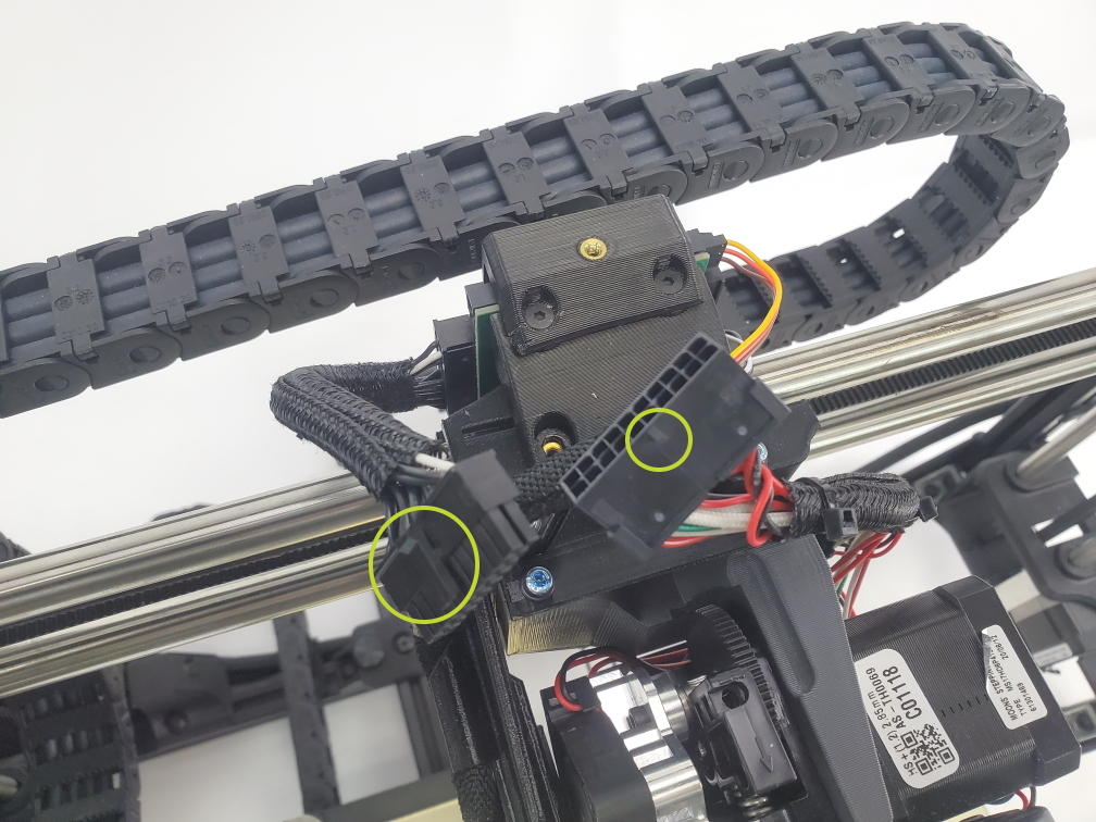
Locate the smaller connector and plug into the top location on x-carriage.
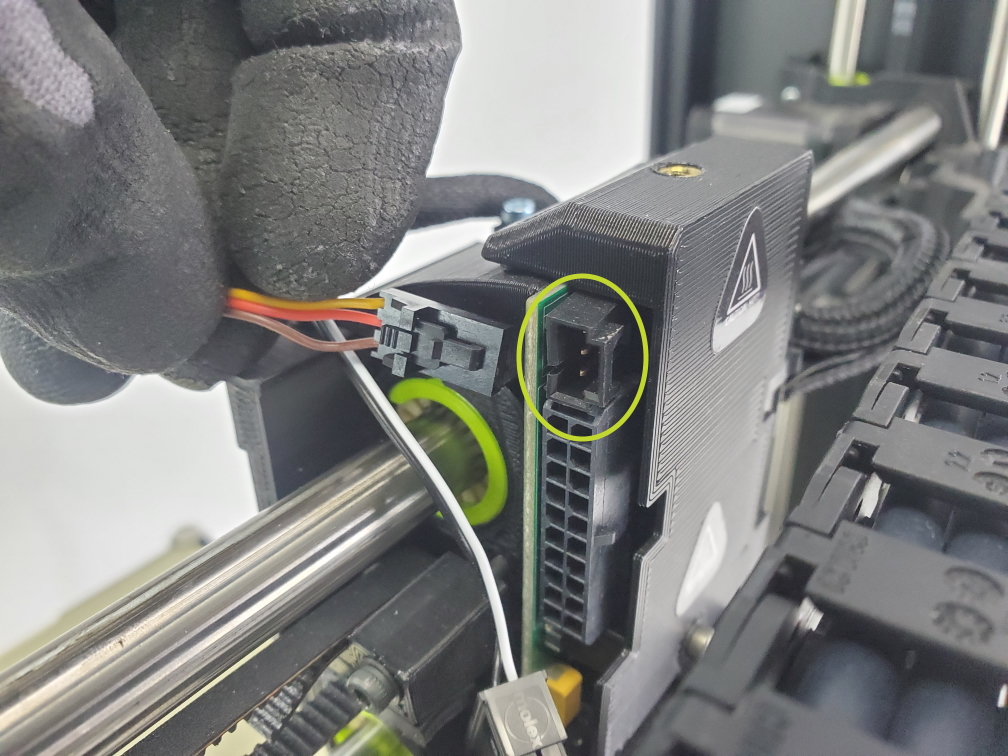
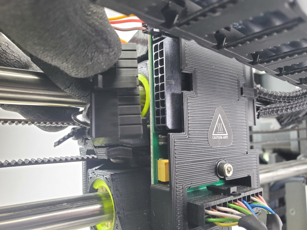
Locate larger black connector and plug into the lower portion of the x-carriage
Make sure both connectors are in the correct ports and are secure.
Note that these will be plugged into the right side of the x-carriage if looking at it from the front.
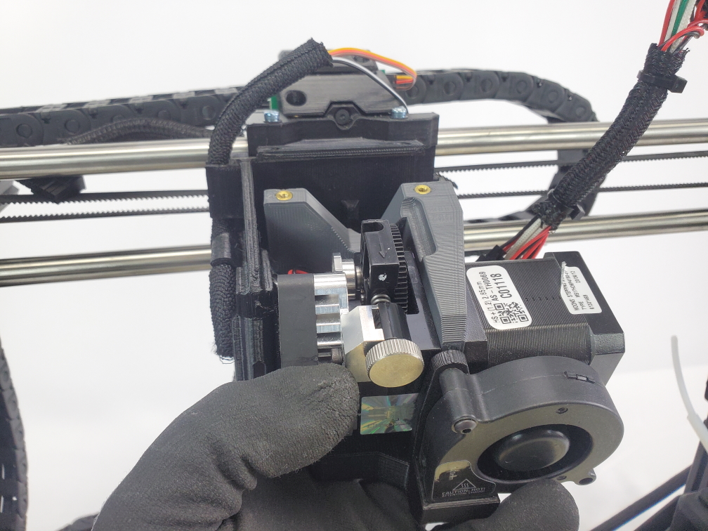
Press the tool head onto the X-axis carriage, aligning the cutouts on the back of the new tool head. Do not pinch any wires between the mount and the carriage.
Secure it to the X-axis carriage by loosely screwing in the top two screws. Leave the top two screws loose.
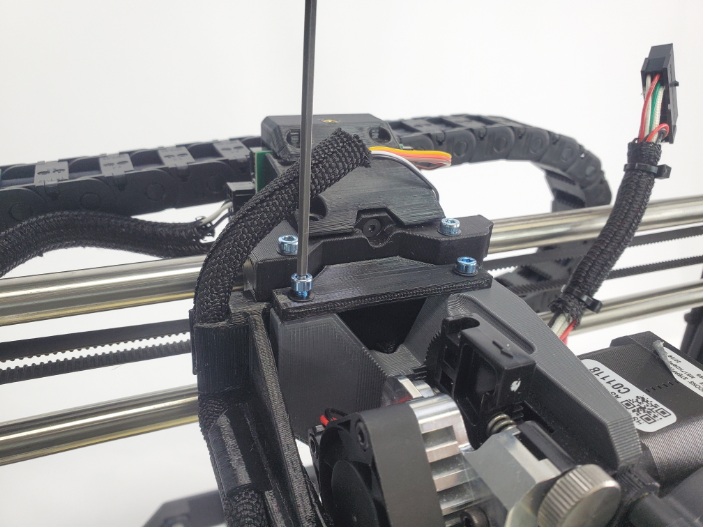
Loosely screw in the last screw through the rear of the X-axis carriage.
Tighten the top two screws.
Tighten the rear screw.
Find the side of the connector on the tool head wiring with a small wedge.
Align it with the clip on the connector from the X-axis carriage and connect them.

Cover the connector with the carriage cap and attach it to the X-axis carriage using the three M3 screws and the 2.5 mm hex key.
Channel the wires together going to down the vertical pathway on the cover mount, and try not to pinch any of the wires when securing the cover. Slide down carefully into place, and hold while screwing in.
Tools
2mm Hex Key
3mm Hex Key
4mm Hex Key
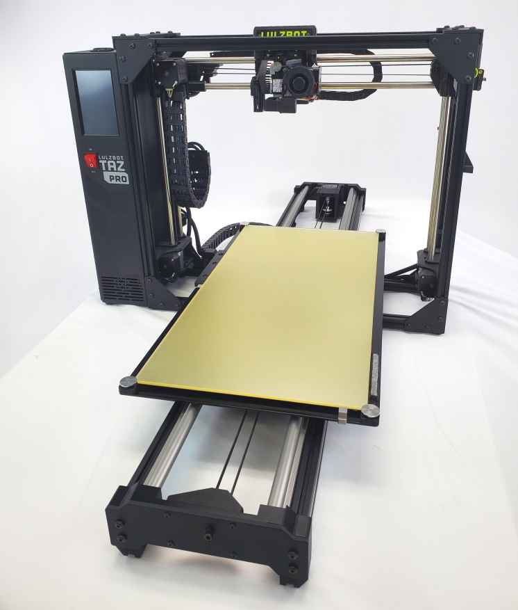
Materials 1x- TAZ Pro S with BL Touch Adaptor installed 1x- Long Bed Assembly with Bed Harness 1x- Hardware Bag
Warning
Make sure the printer is turned off and unplugged since it is required to open a part of the electrical box.
It is recommended use two people when moving the Long Bed to avoid damage.

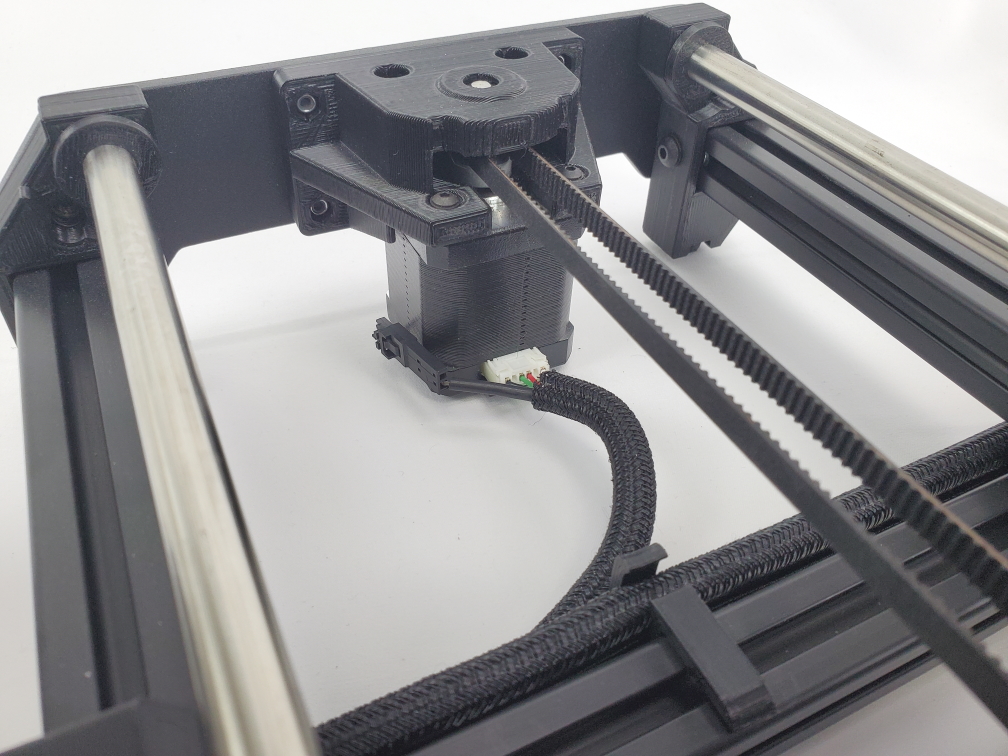
Locate and disconnect the y-axis motor and ground wire
Disconnect the three wires that are connected to the bed heater.
Using the 4mm Hex Key remove the bed harness that is connected to the bed.
Remove the four thumb screws that are securing the Y axis. Once the four thumb screws are removed, pick the Y axis up and set it a side. Watch for any wires that are still connected to the Y axis while moving it!
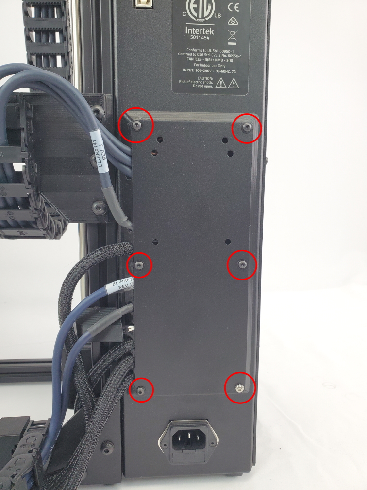
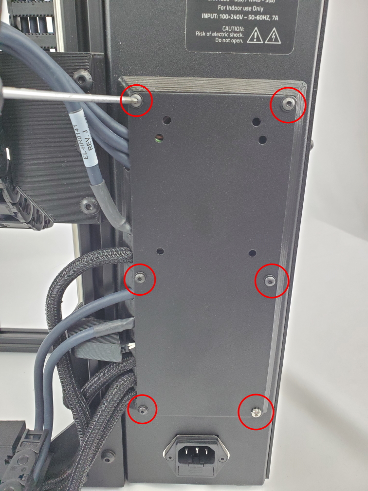
Use a 2mm Hex Key to remove the 6 screws on the rear cover of the electronics case.
Keep track of these screws they will be needed to close the electronics case!
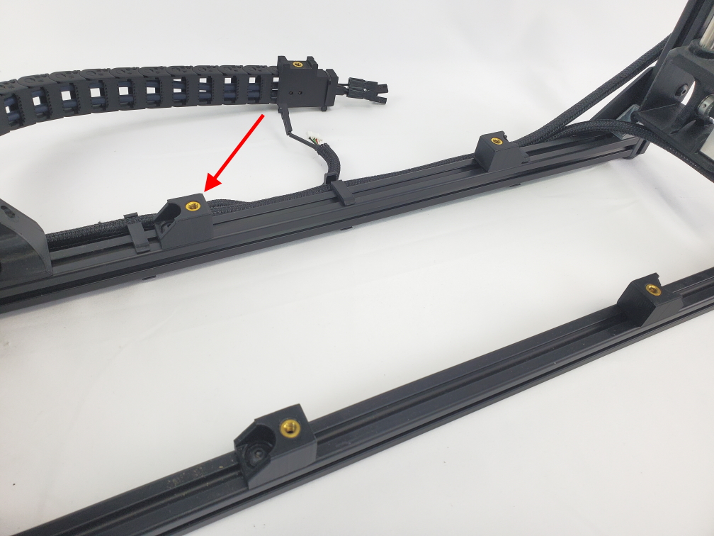
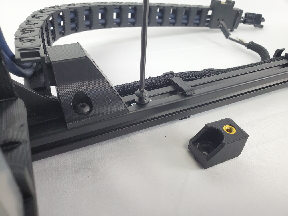
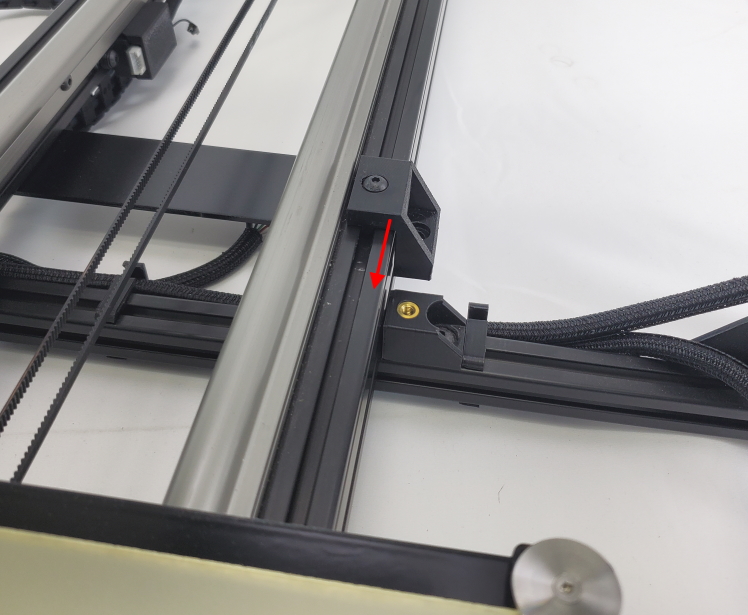
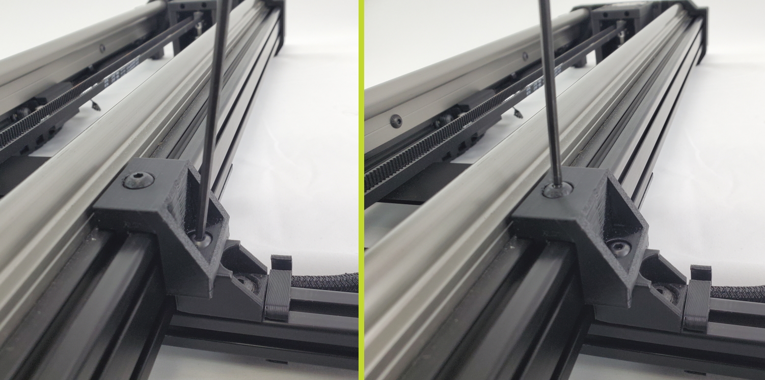
Use the 3mm hex key to remove the rear left bed mount bracket. This is the bracket by the bed harness mount.
Once the bed mount is removed slide the T-slot nut between the wire clip and the bed harness mount.
Fasten the screw and washer from the bed mount bracket back into the T slot nut.
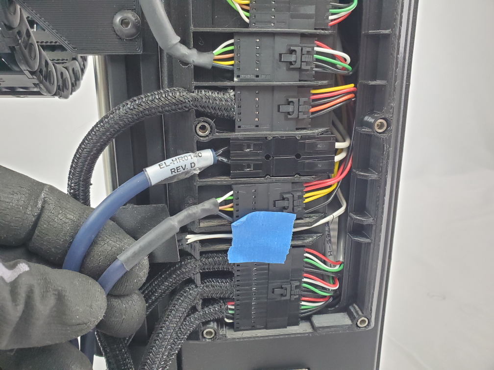
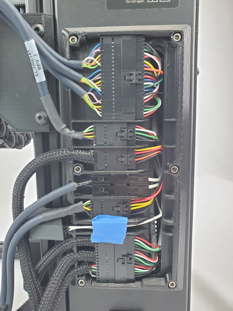
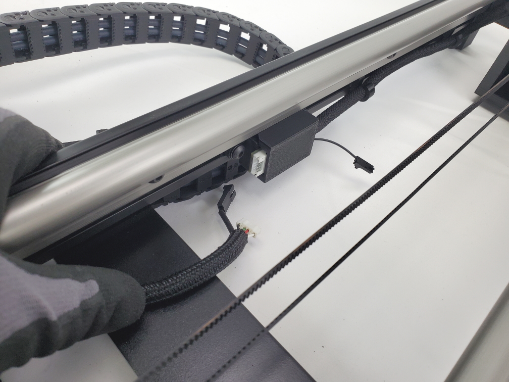
Before disconnecting the bed harness, trace the two blue wires from the bed harness wire chain back to the electronics box.
Disconnect the two wires once you identified where the blue wires are connected to the electronics box.
Use the 2mm hex key to remove the screw that is securing the end of the bed harness chain.
Be care not to lose this screw!
Set the bed harness to the side.
The Standard TAZ Bed is now fully removed you should have the following items:
You can put these parts it storage since they will not be needed for the Long Bed. We recommend you reuse the hardware bag from the long bed for the thumb screws and place all the items inside your TAZ Pro S product box for storage.


Gather materials needed for installing bed harness.
Items needed:
- Long bed cable chain
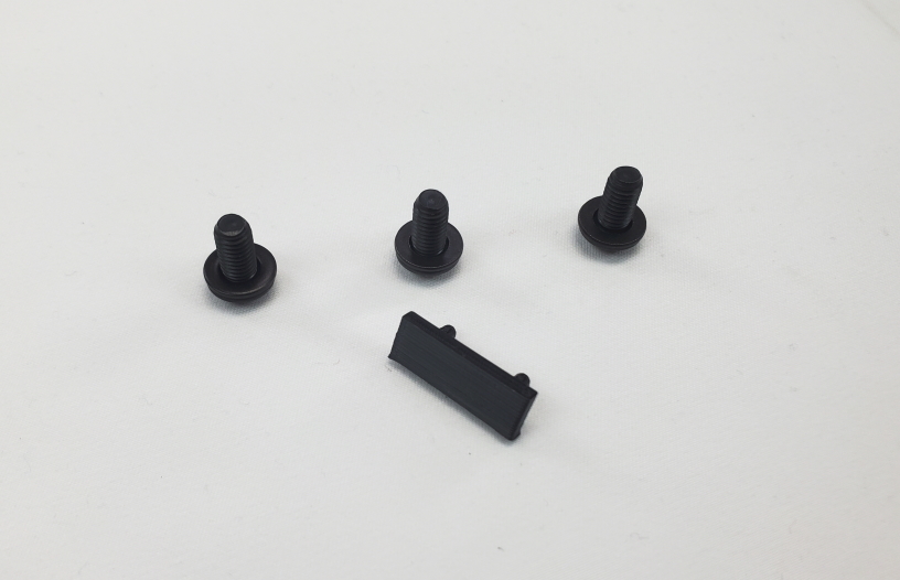
- Rear panel
- 6x Panel screws w/ washers
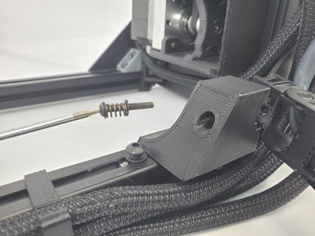
- Cable Chain screw, spring, and washer
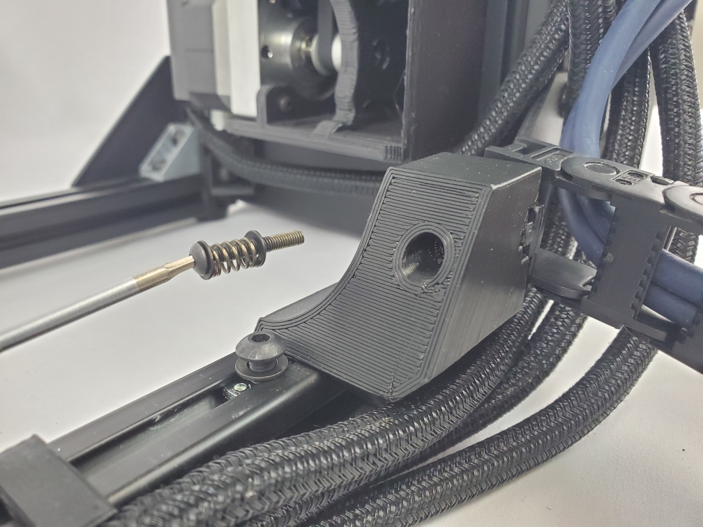
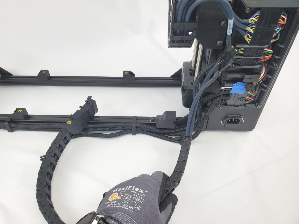
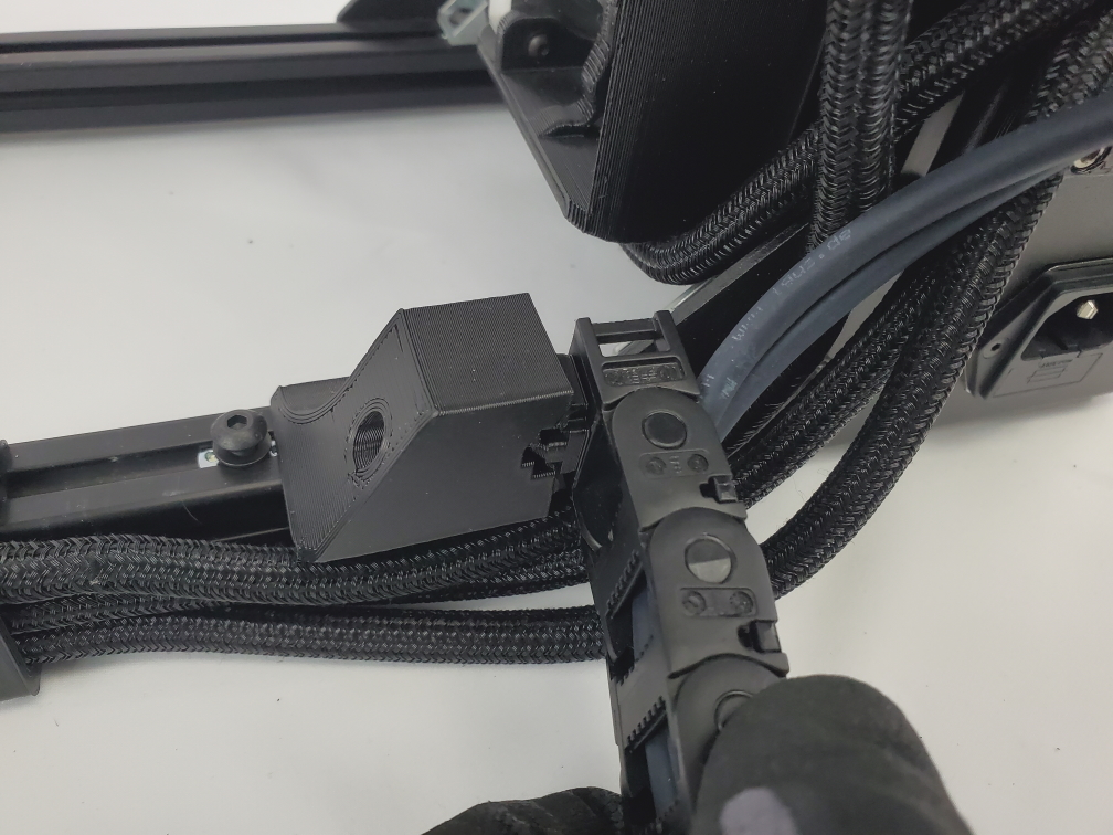
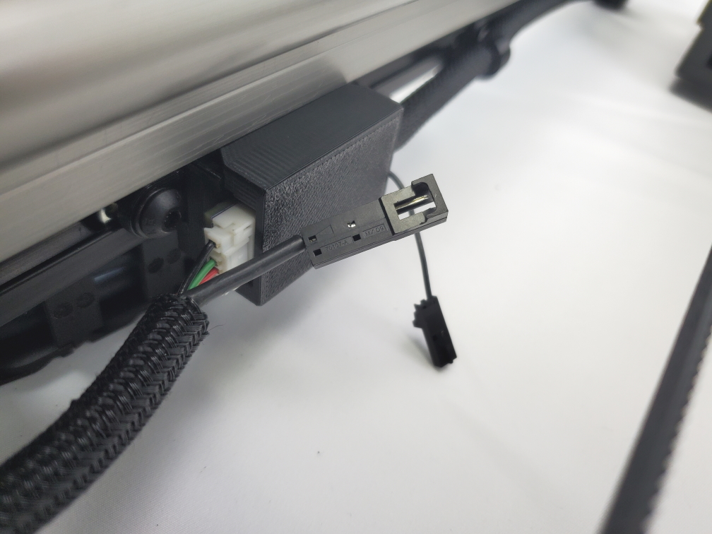
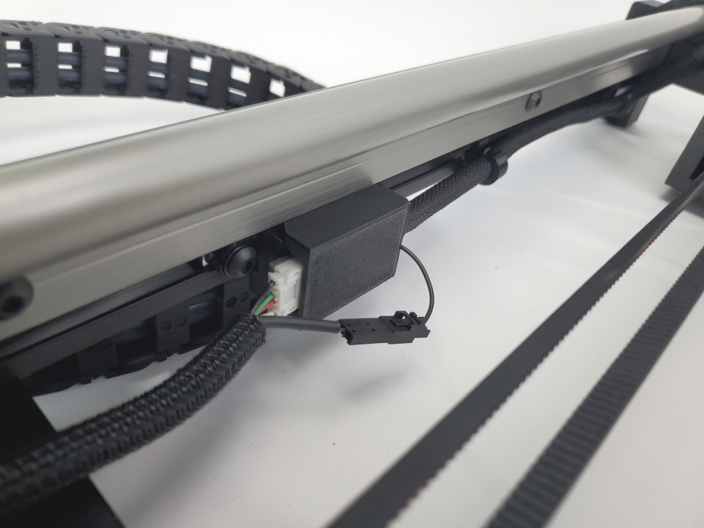
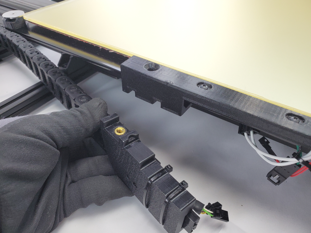
Align the end of the bed harness with the bed harness mount on the frame. Make sure its the small printed part not the larger printed part.
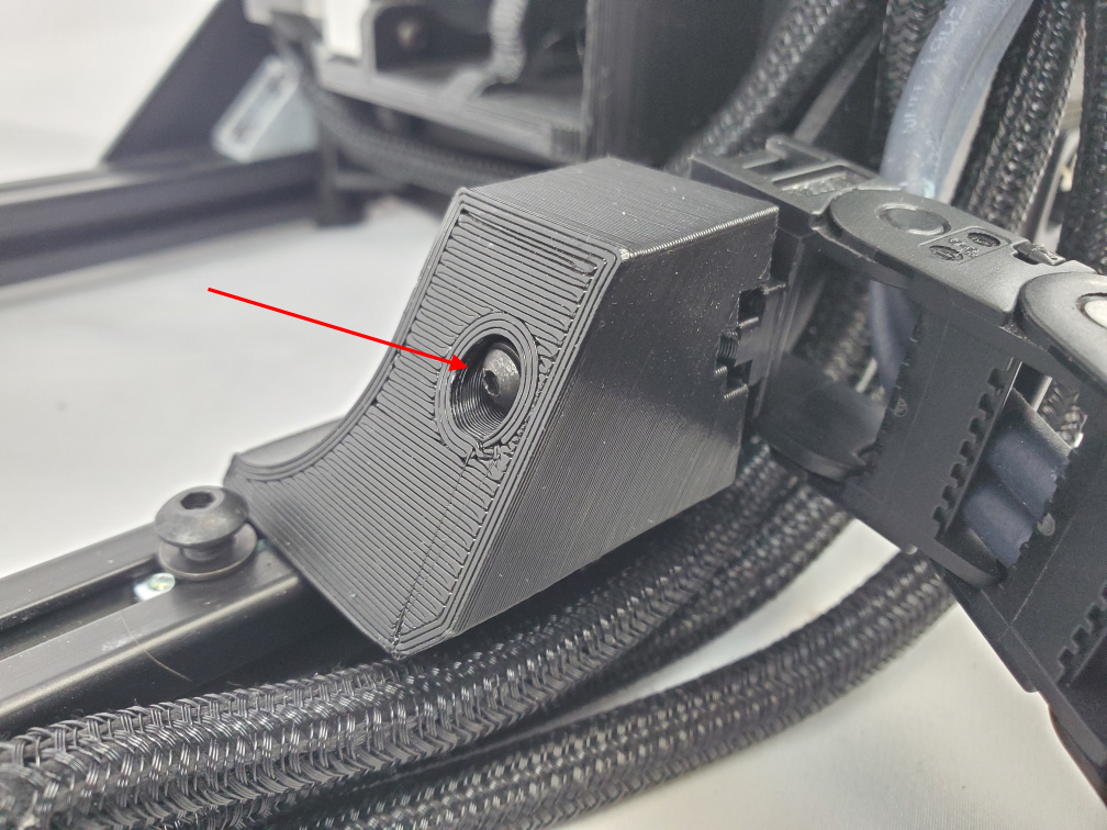
Once the printed part is aligned with the harness mount, use a 2mm screw to secure the bed harness to the frame using the cable chain screw, spring, and washers previously removed from this location.

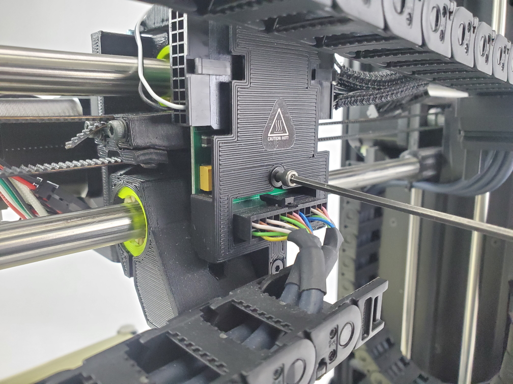
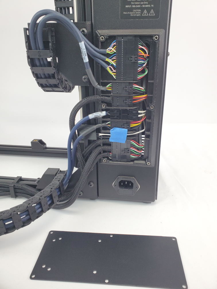
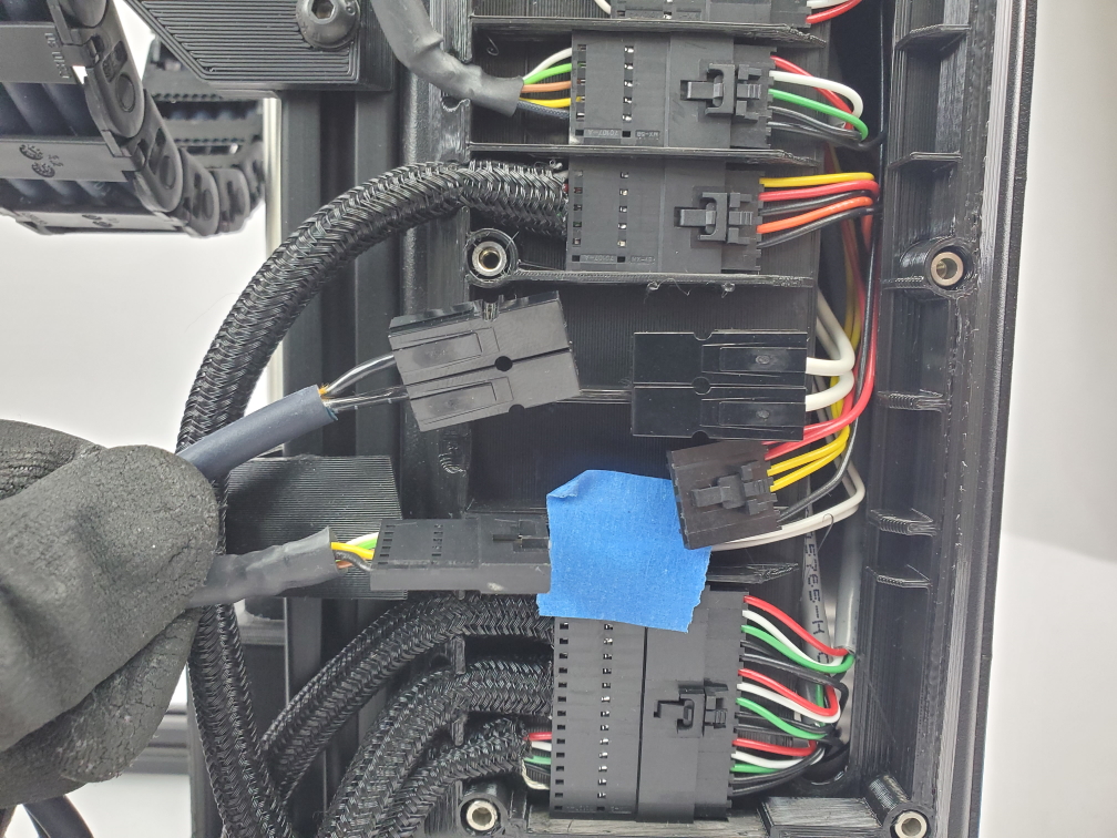
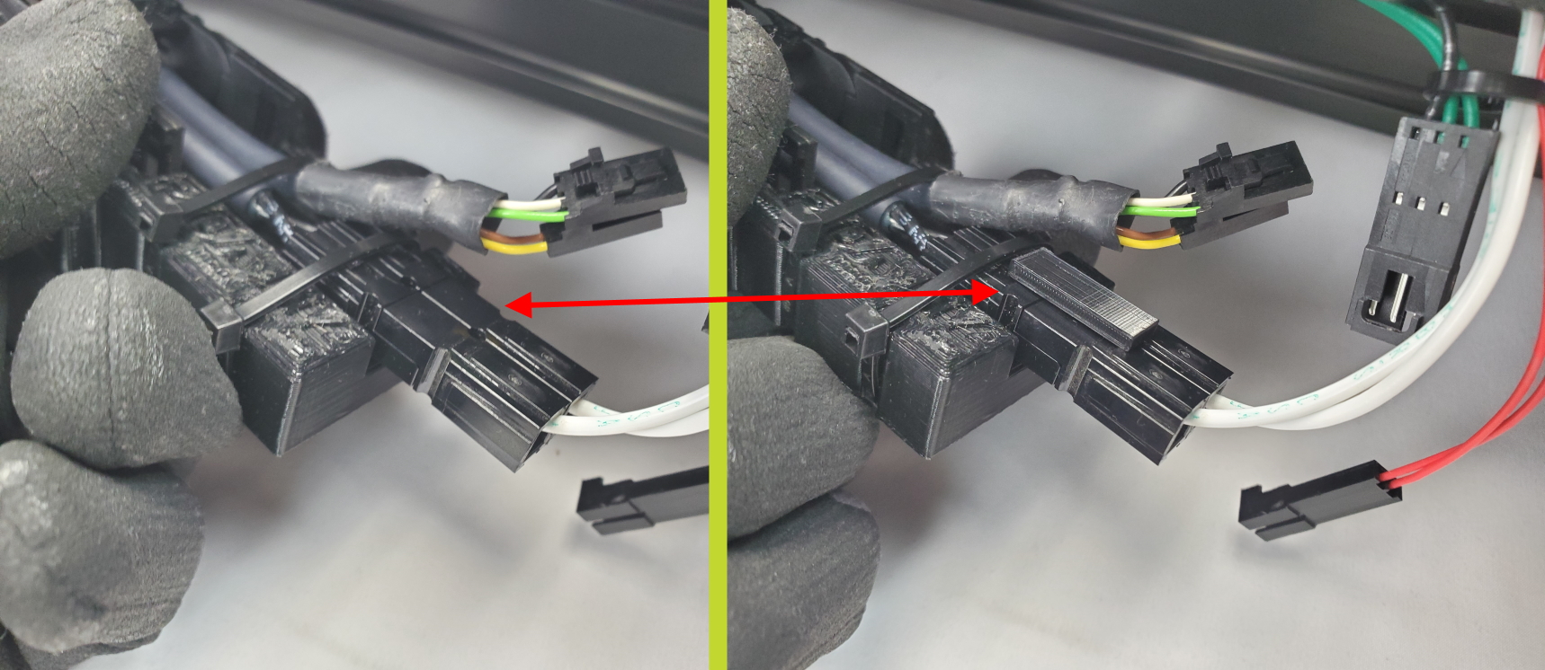
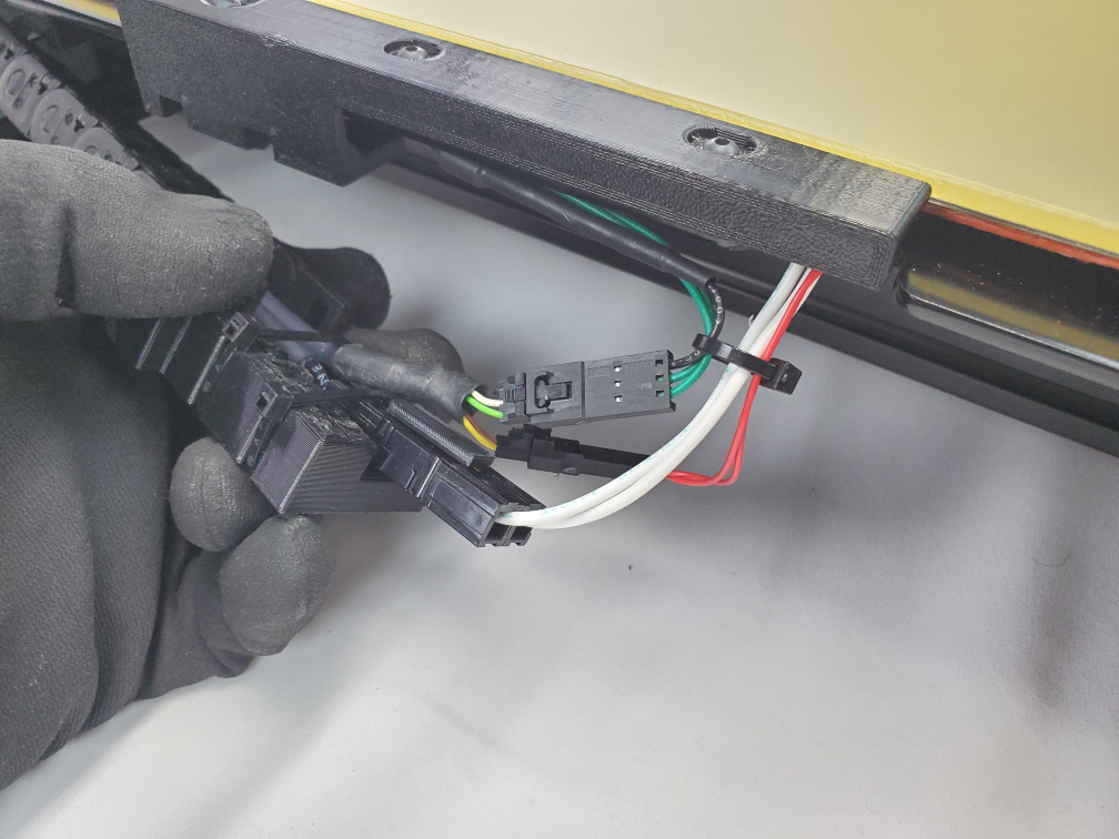
Connect the bed harness to the electronics case by connecting the two wires that are inside the wire chain to the electronics case.
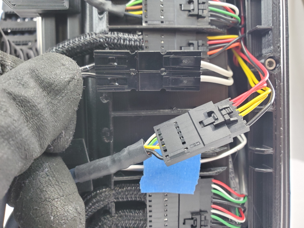
Find the harness that has 5 wires and connect it to the connector inside the electronics case that has black, yellow, and red wires. Once its connected gently pull on both connectors to ensure they have a secure connection. Then push the connectors into the connector divider.
Take the harness that has two black wires and connect it to the two white wires inside the electronics box.
Push the connectors for the black and white wires between the four knobs in the connector divider.
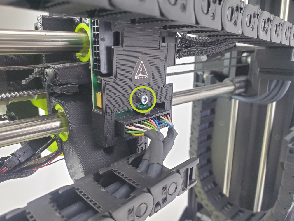
Once the bed harness is connected to the electronics box, you can replace the cover using the same six (6) bolts to attach the cover to the electronics case. Place the sliver bolt with it's lock washer in the bottom right hole.
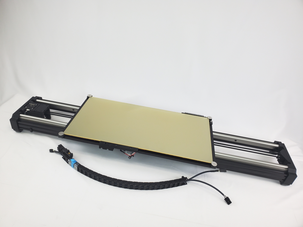
We recommend to use two people for this step since you are required to move the Long Bed. This is recommended to avoid damage.
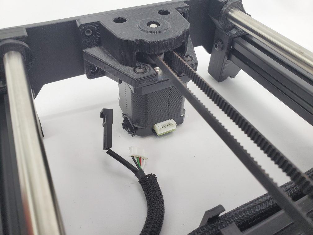
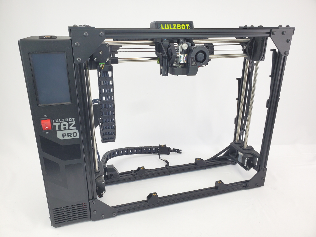
Take the long bed assembly and place it inside the printer's frame. Making sure the motor is on the backside with the wiper pad on the right side.
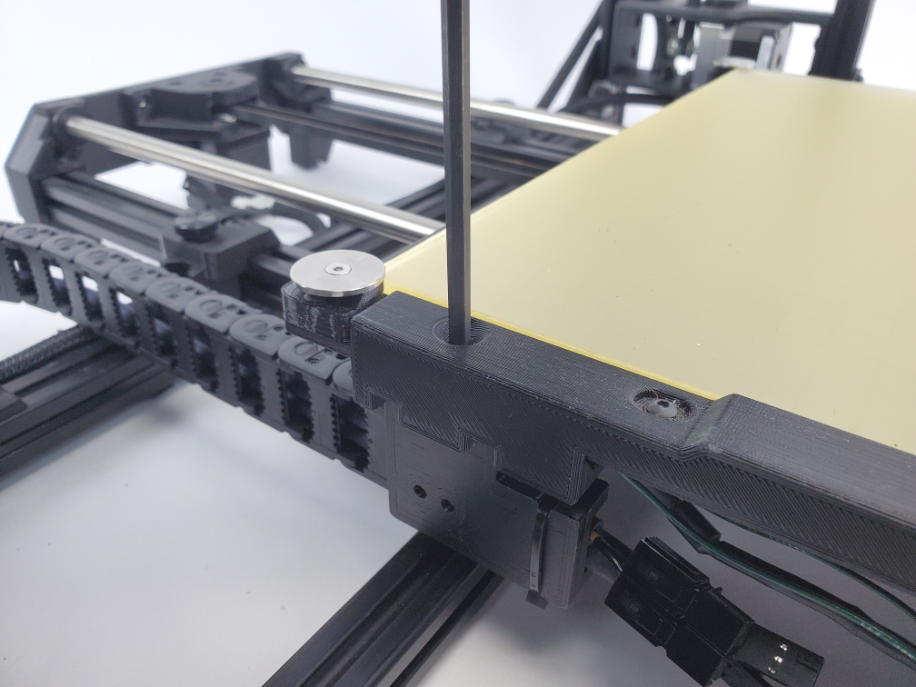
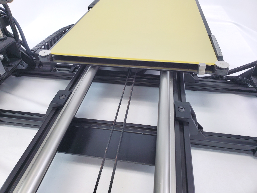
While setting the long bed inside the frame make sure to align the three bed mount brackets.
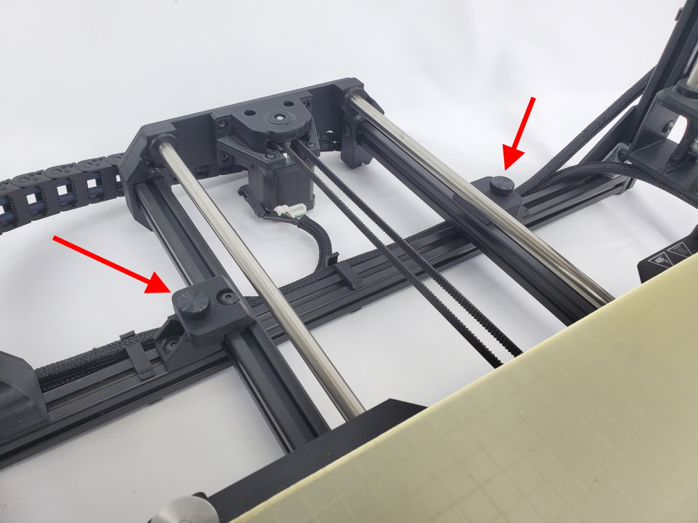
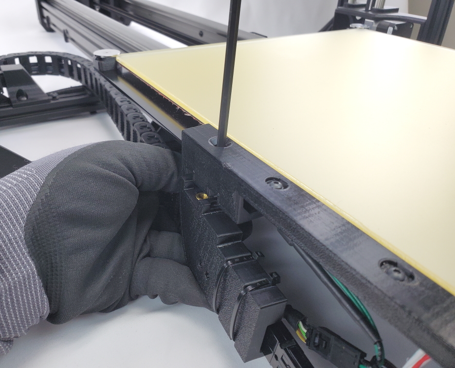
Then using a 3mm hex key along with the three bolts inside the hardware bag attach the Long bed to the frame.
On the rear right corner, you may need to secure both screws in place.
Start with the lower bolt, then secure the upper bolt.
Optional: Use a square to center the long bed before mounting it to the frame. If you don't have a square to your best to center the long bed with the TAZ frame.

On the backside of the TAZ frame find the three wires that are inside the wire clips.
Look for the Y motor harness and remove it from the wire clips.
Route the Y motor harness above the black bottom support on the Long Bed.
Then connect the Y motor harness to the Y harness adaptor mounted on the left extrusion on the Long Bed.
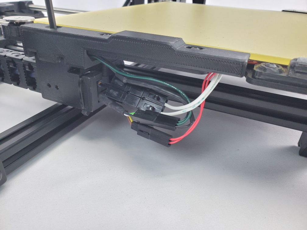
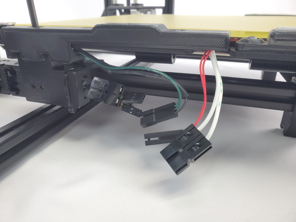
Take the bed harness and connect the three wires to the three wires attached to the Long Bed.
Make sure all the connections are secure by gently pulling on each end.
Then use a 4mm hex key to attach the bed harness the bed plate.

Before attempting to power on the printer, make sure you have done the following:
Once these have been completed you are ready to install/update your Cura LE software and flash firmware!

Install the latest version of Cura LulzBot Edition (Must be Cura 3.6.38 or newer). It is important to have the LulzBot Edition of Cura, as it has preset machine configuration profiles built into it.
Go to LulzBot.com/Cura to install Cura LulzBot Edition.
Plug in your LulzBot TAZ Pro 3D printer to the power supply and power on your 3D printer.
Once powered on, connect your 3D printer to your computer using the USB cable.
Open Cura LulzBot Edition.

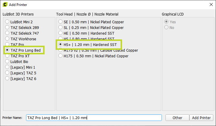
Select Settings dropdown > Printer > Add Printer
Select the LulzBot TAZ Pro Long Bed in the first column, then select the HS+ | 1.20 mm | Hardened SST tool head from the second column, and click Add Printer.
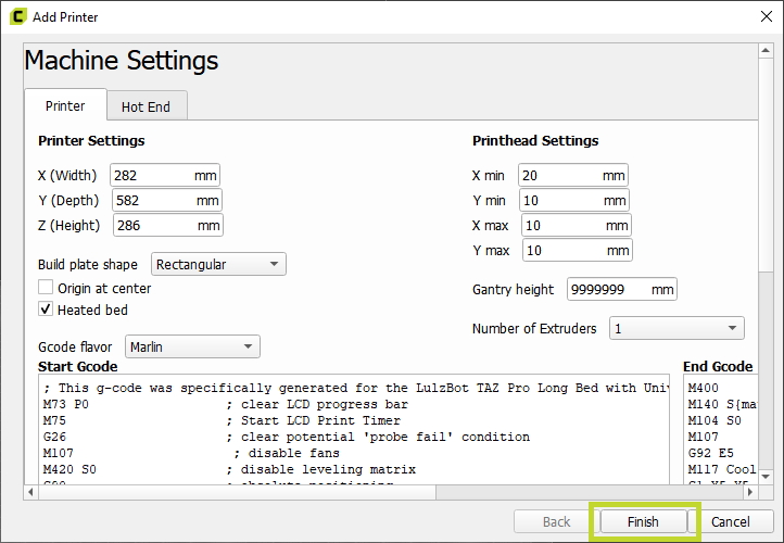
Select Finish.

Note: You do not need to click connect in Cura to flash firmware.
Proceed directly to menu for flashing firmware below.
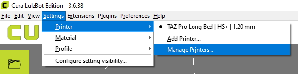
Select Settings dropdown > Printer > Manage Printers.
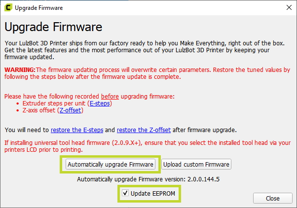
Confirm the LulzBot TAZ Pro Long Bed and HS+ tool head are selected, and click Upgrade Firmware.
Select Automatically Update Firmware.

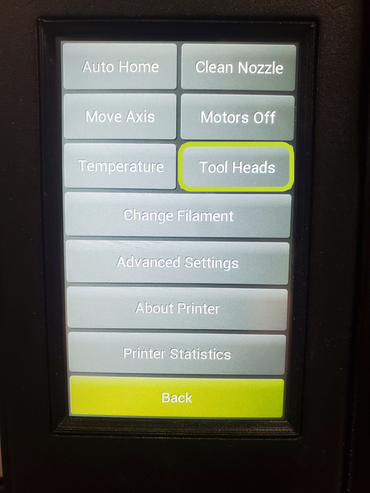
Navigate to the first menu screen on your printers LCD and select the Tool Heads menu.
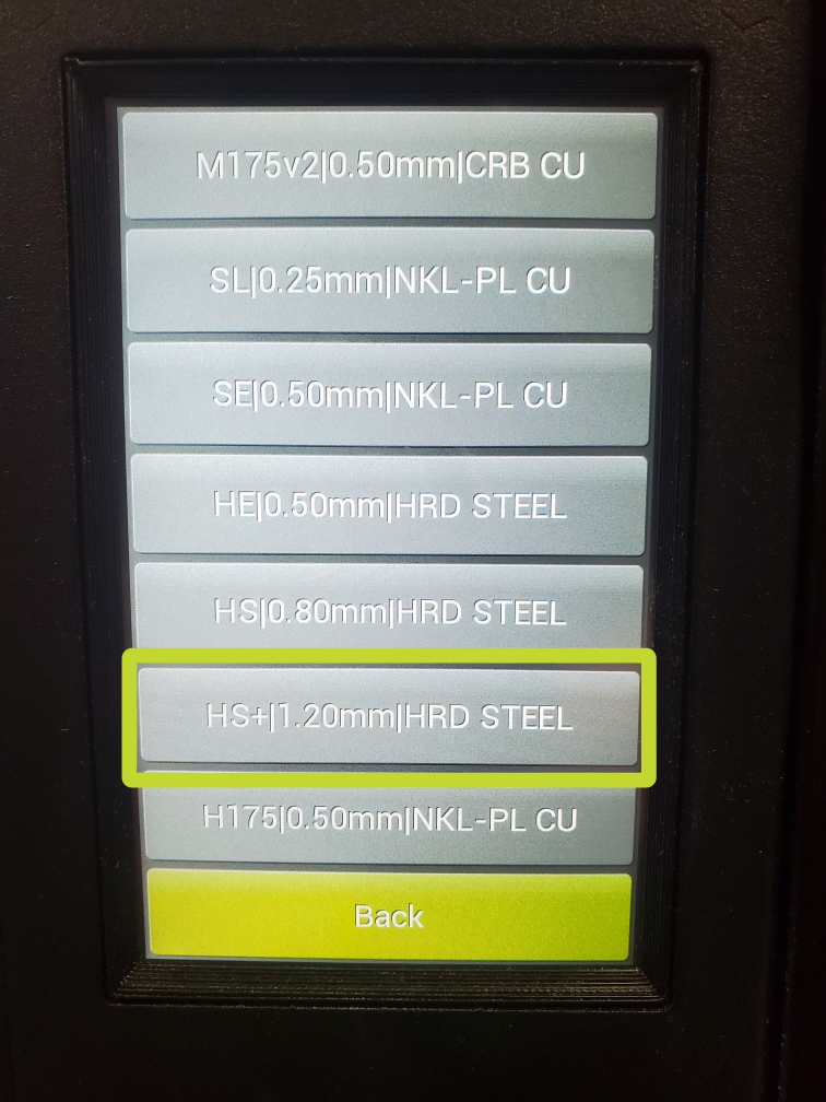
Scroll down until you find the HS+ tool head and select it.
Double check that all previous steps have been completed.
- Installed the BL Touch adaptor
- Installed the HS+ tool head
- Completed the Long Bed Installation
- Updated firmware and selected correct tool head.
Once confirmed, your printer is ready to start printing!
