Open HardwareAssembly Instructions
Guides for installation and assembly of the LulzBot line of products made by FAME 3D LLC.
Guides for installation and assembly of the LulzBot line of products made by FAME 3D LLC.
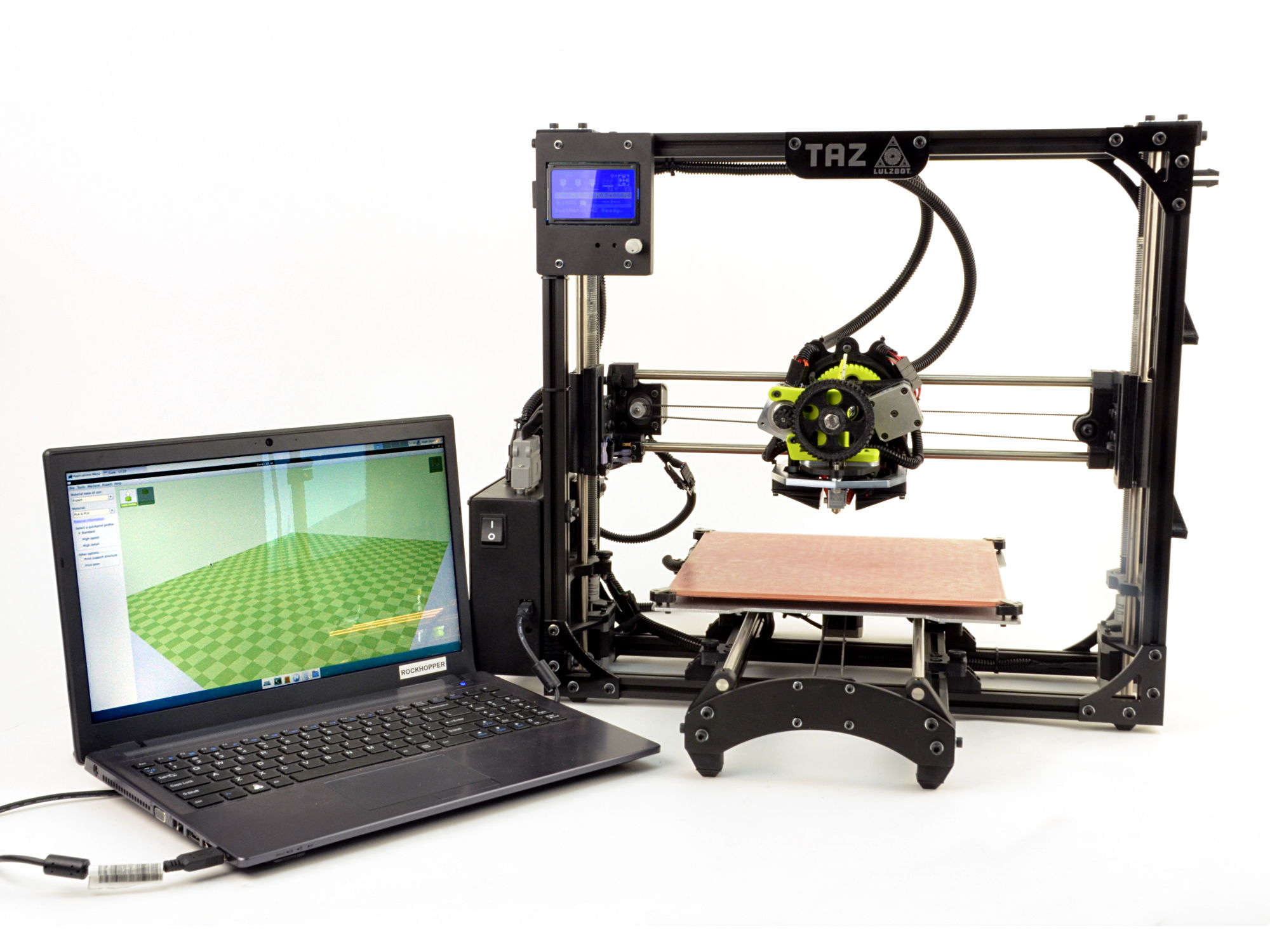
You just upgraded your LulzBot desktop 3D printer with the LulzBot® TAZ FlexyDually Tool Head v2. After following this Quick Start Guide, your LulzBot TAZ 3D printer will be more capable than ever.
Let's get started!
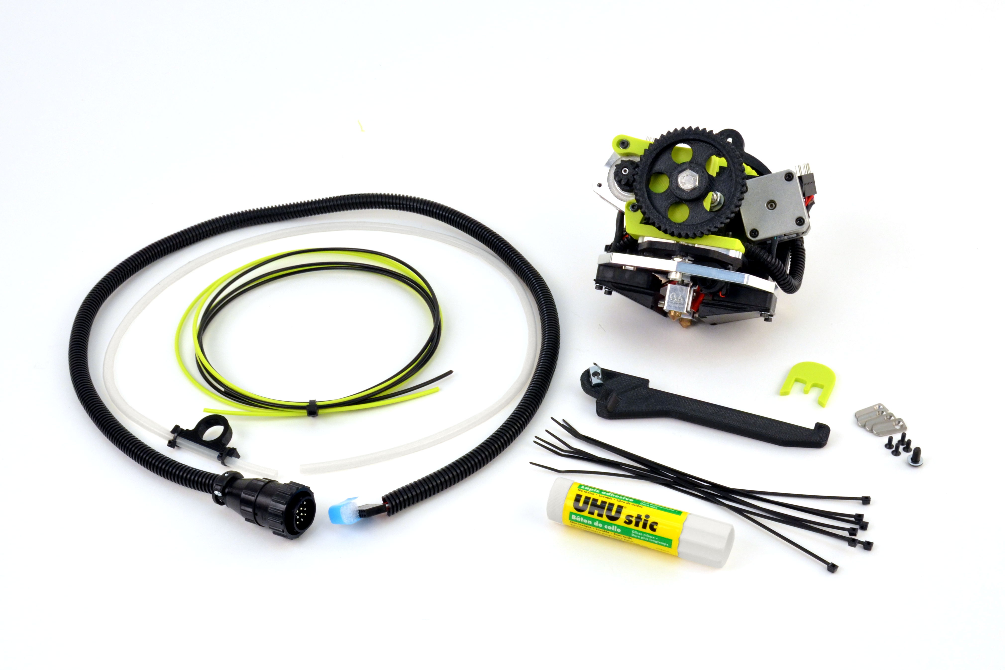
You will also need
Let's get started!
4A
Power on your LulzBot TAZ 3D printer.
4B
Home your 3D printer by using the Graphical LCD controller to home the printer.
4C
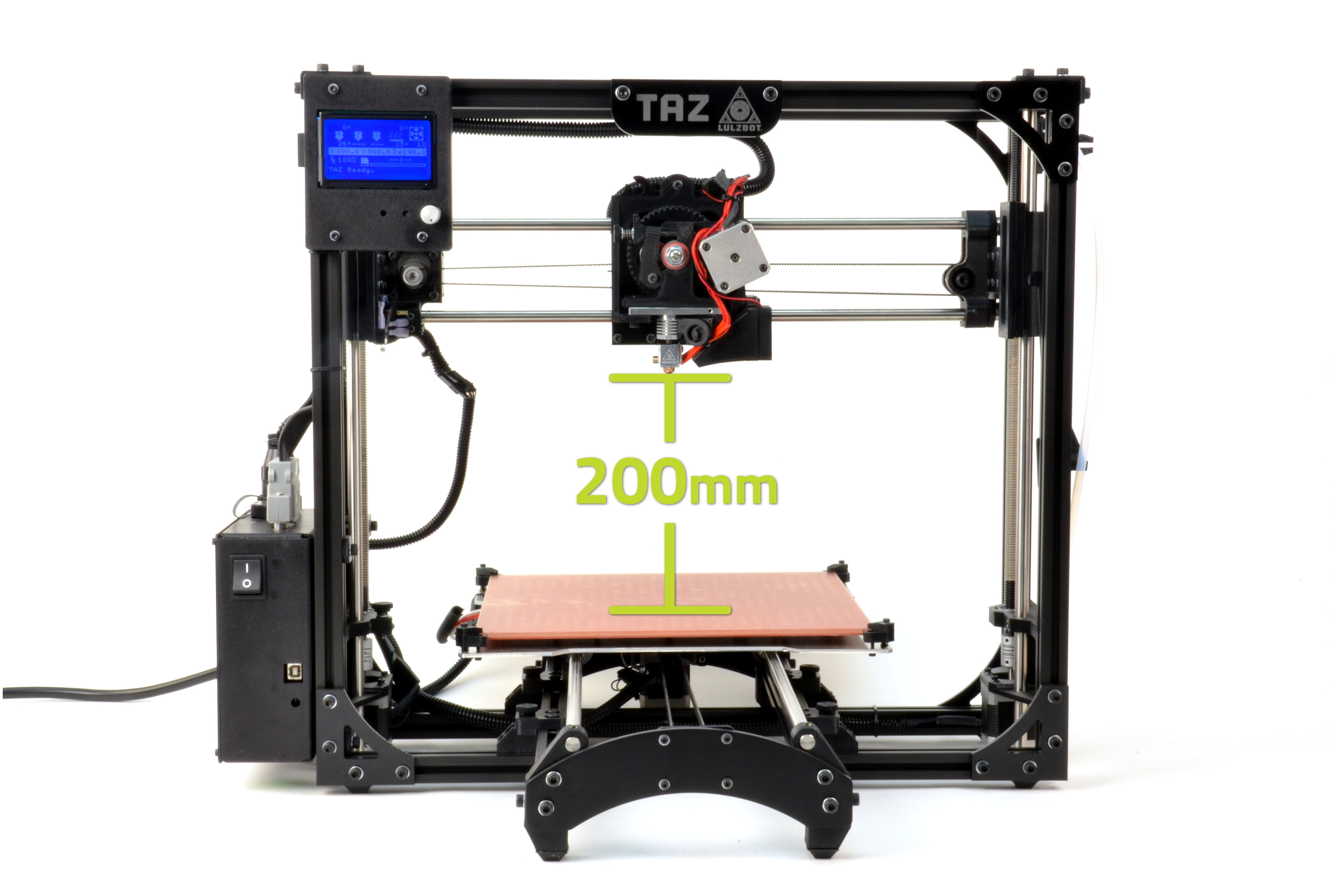
Raise the Z axis through the Graphical LCD controller.
Navigate to:
Prepare > Move Axis > 1.0 > Z axis > Change the value to at least 200.
4D
After the Z axis stops moving, push the X axis carriage over by hand to the middle of the X axis.
Completely power off your LulzBot 3D printer and unplug the power supply before proceeding.
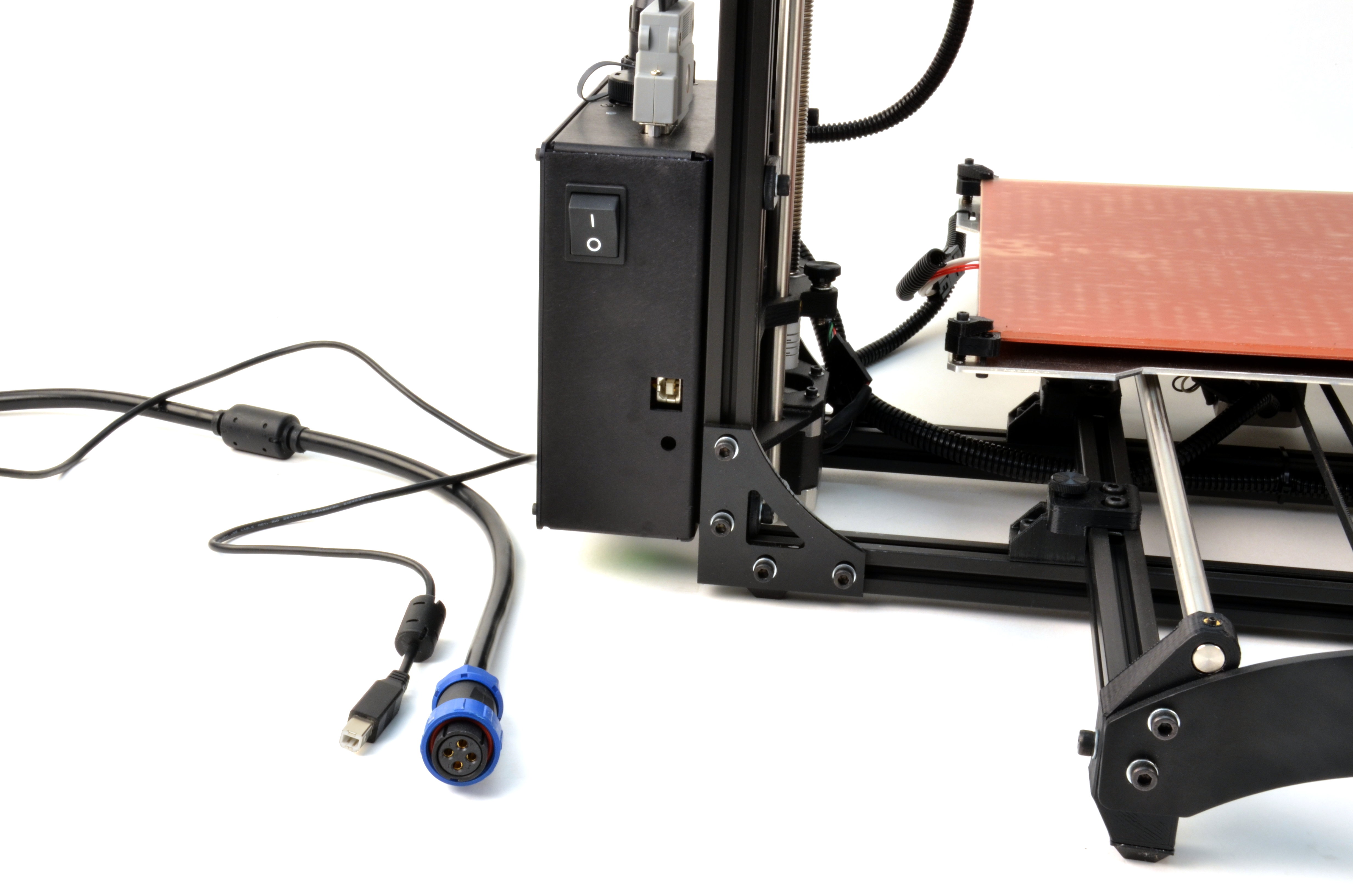
Your new tool head has a different hot end length than the standard tool head on your LulzBot TAZ. A screw used to attach the control box to the LulzBot TAZ 3D printer frame will need to be replaced.
6A
The screw is located on the rear, left-hand side vertical extrusion.
6B
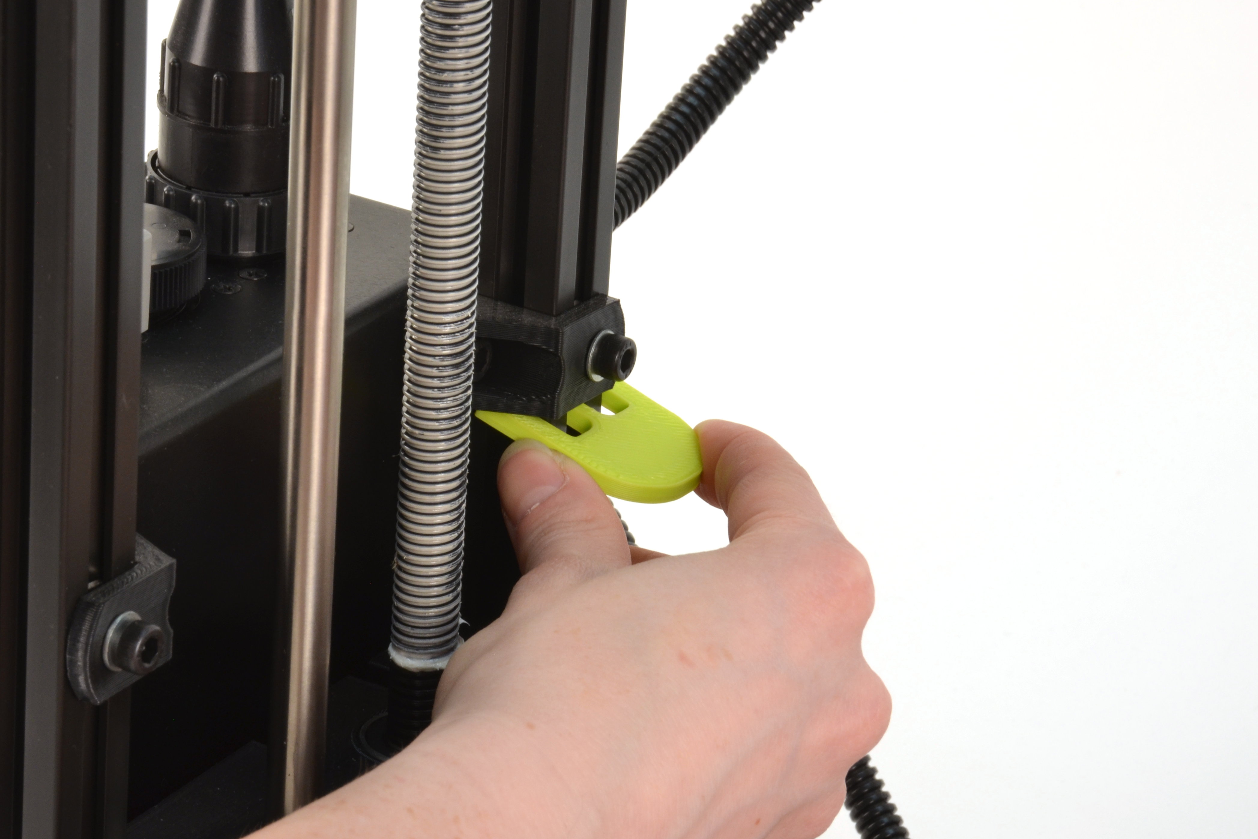
Hold the upper T-nut in place with the T-nut jig.
Insert the jig into the aluminum extrusion channel prior to removing the screw. If it does fall lift it back up.
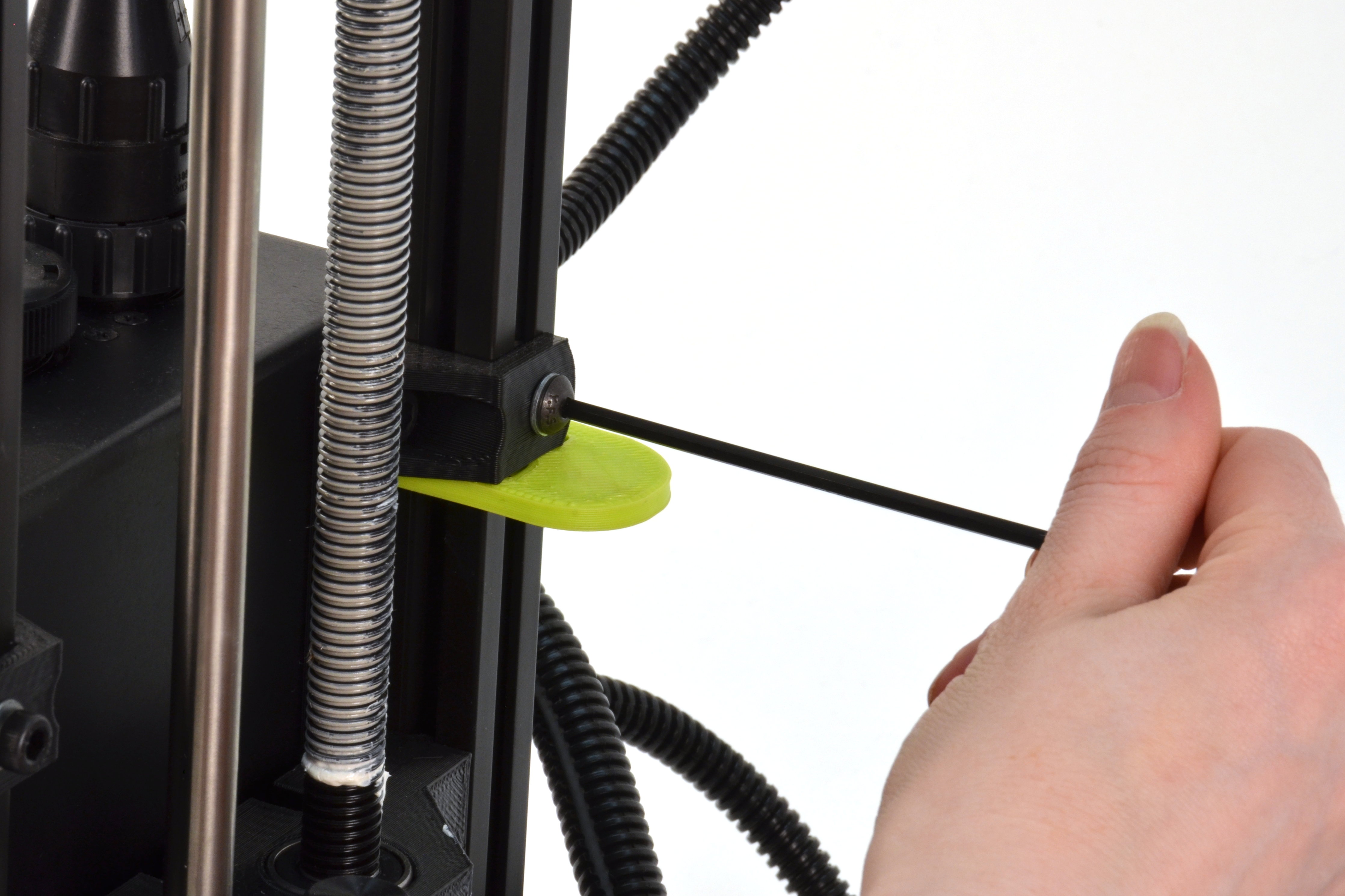
6C
Remove the top rear 10mm M5 bolt and replace it with the lower profile 8mm M5 screw.
6D
Remove the jig once the screw has been replaced.
Additional clearance is necessary for the extrusion fan ducts on your new dual extruder.
7A
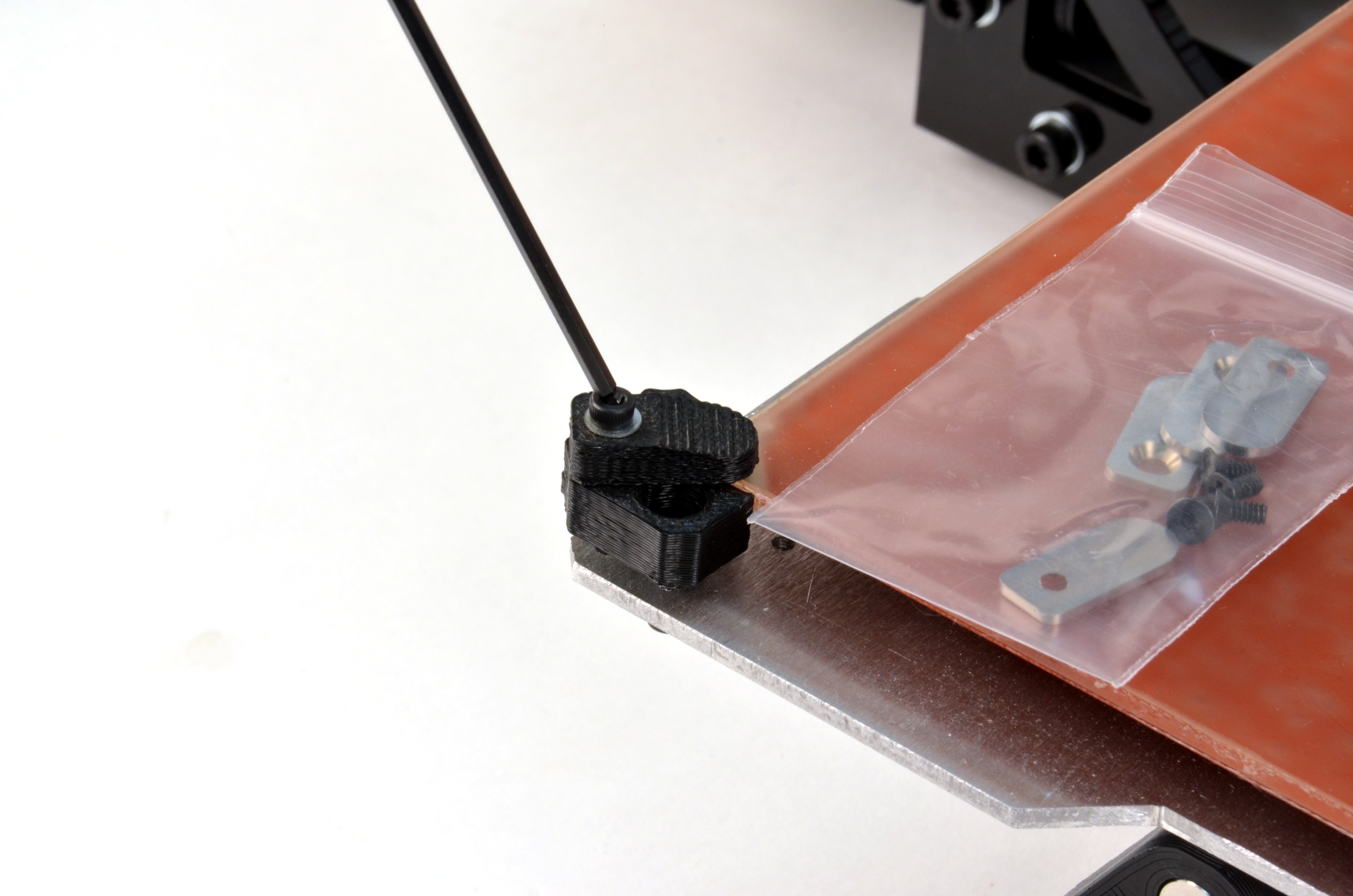
Remove the four original 3D printed bed corner fingers using a 2.5mm hex driver.
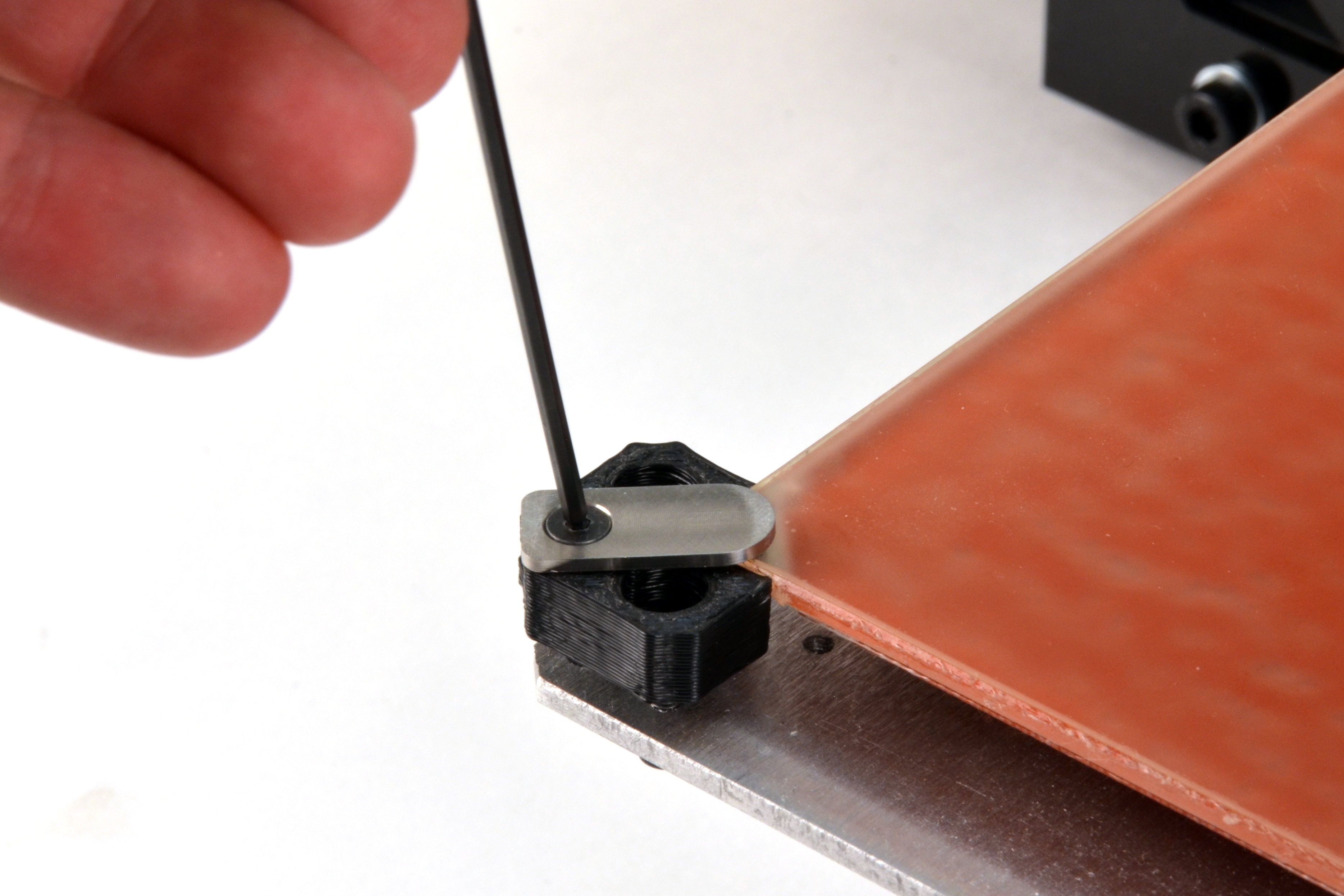
7B
Using a 2mm hex driver and the included 3mm flat head screws replace the bed corner fingers with the new lower profile aluminum bed holster plates.
8A
Loosen the existing spool arm and slide it down about 2 inches (50mm), and tighten it.
8B
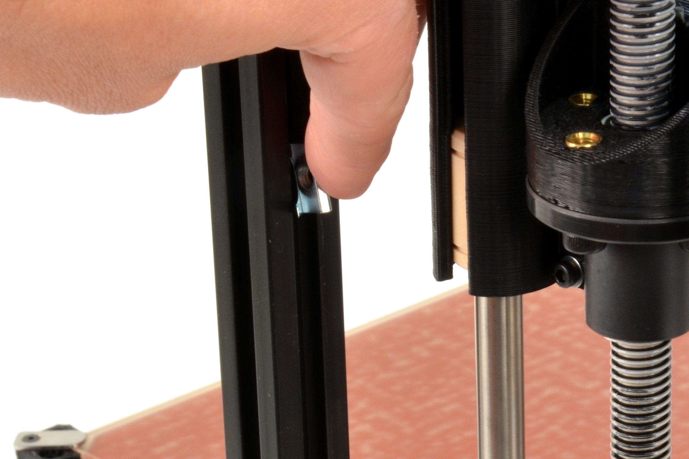
Insert the new T-nut included with your Dual Extruder Tool Head v2 on the same z-axis vertical frame (the front right extrusion), in the same channel.
8C
Use the M5 screw to install the 3D printed secondary filament spool arm.
8D
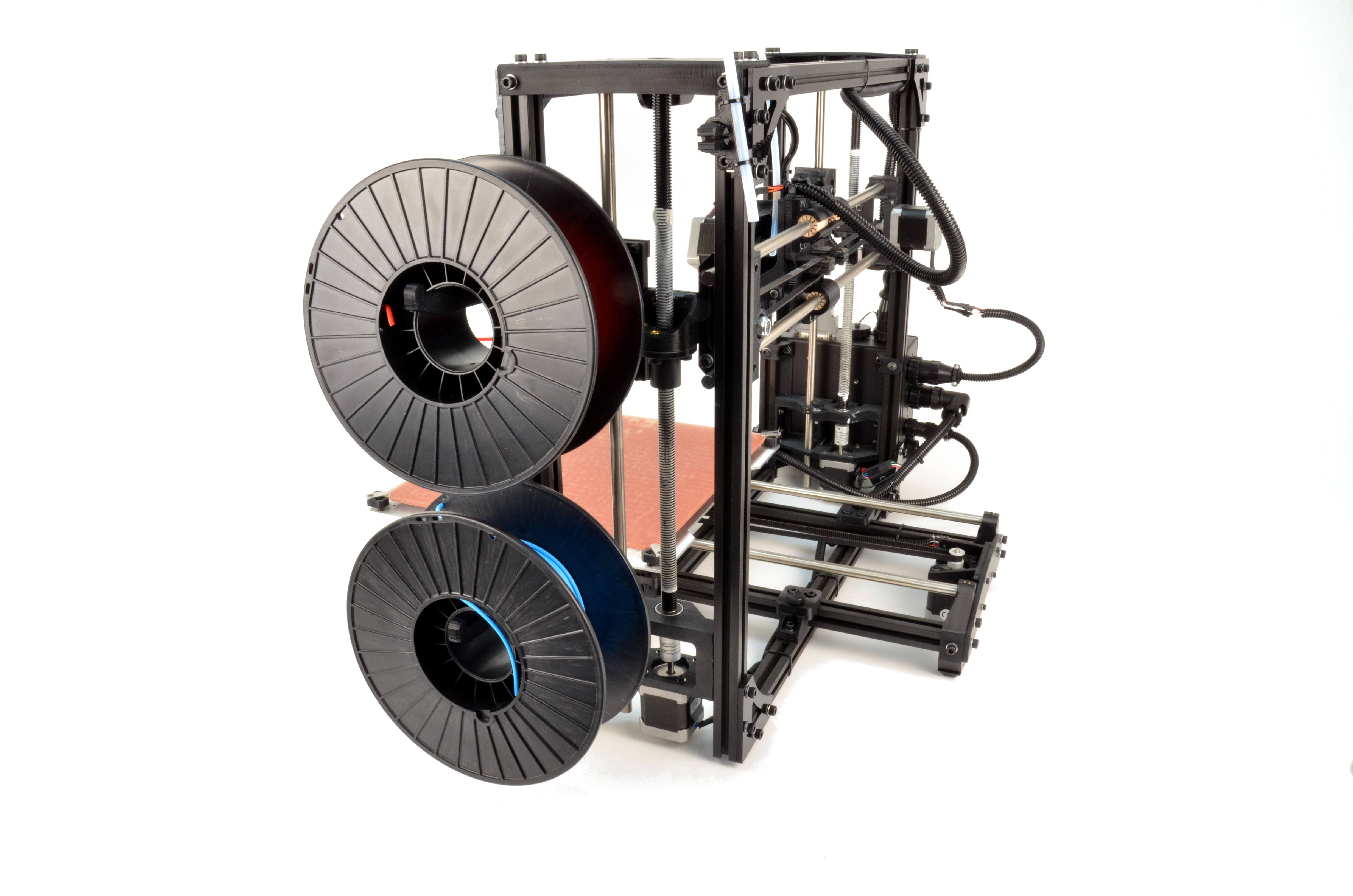
Place two spools of filament on the spool arms to ensure they are mounted with sufficient space to rotate during printing.
8E
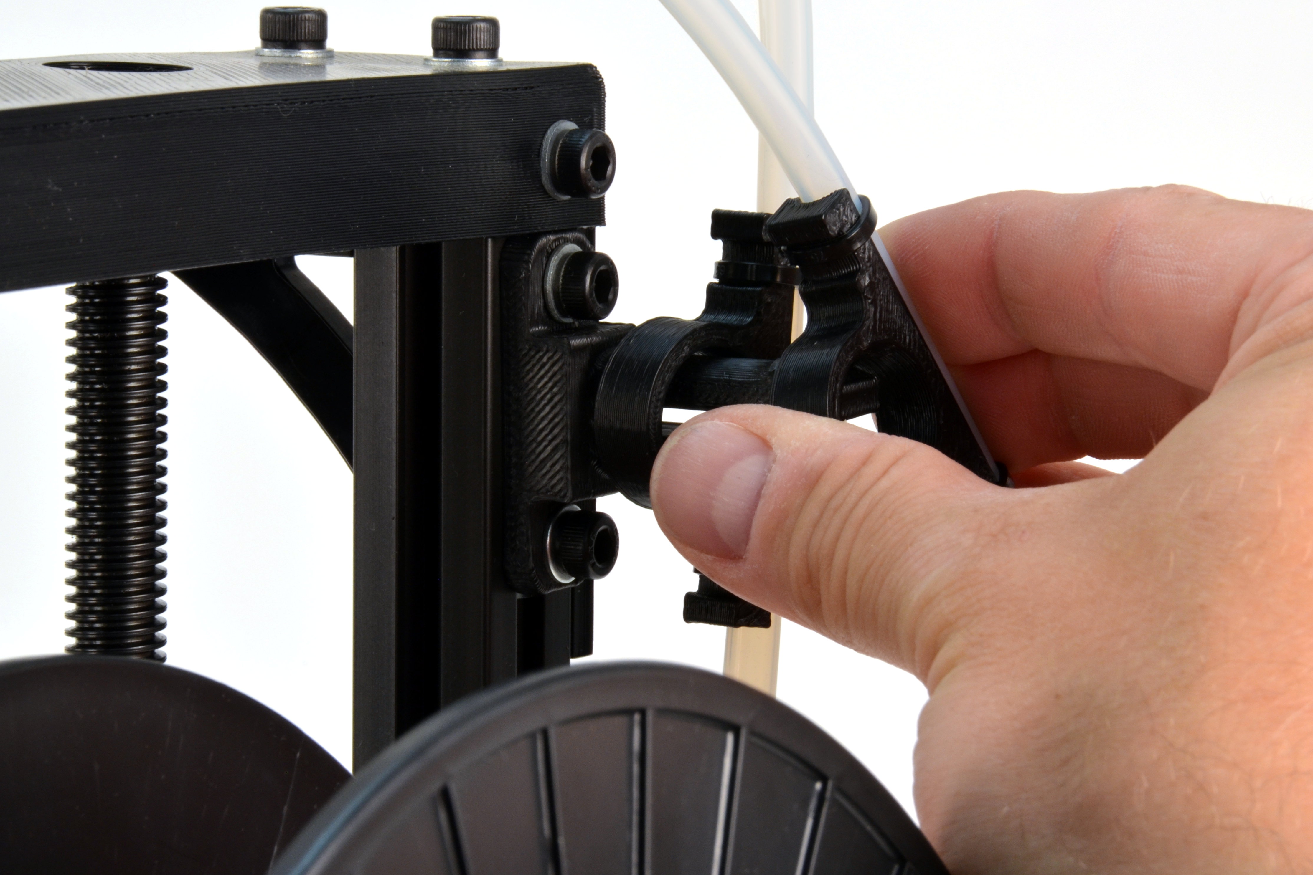
Attach the secondary filament guide tube included with your new dual extruder, matching the existing feed tube orientation.

9A
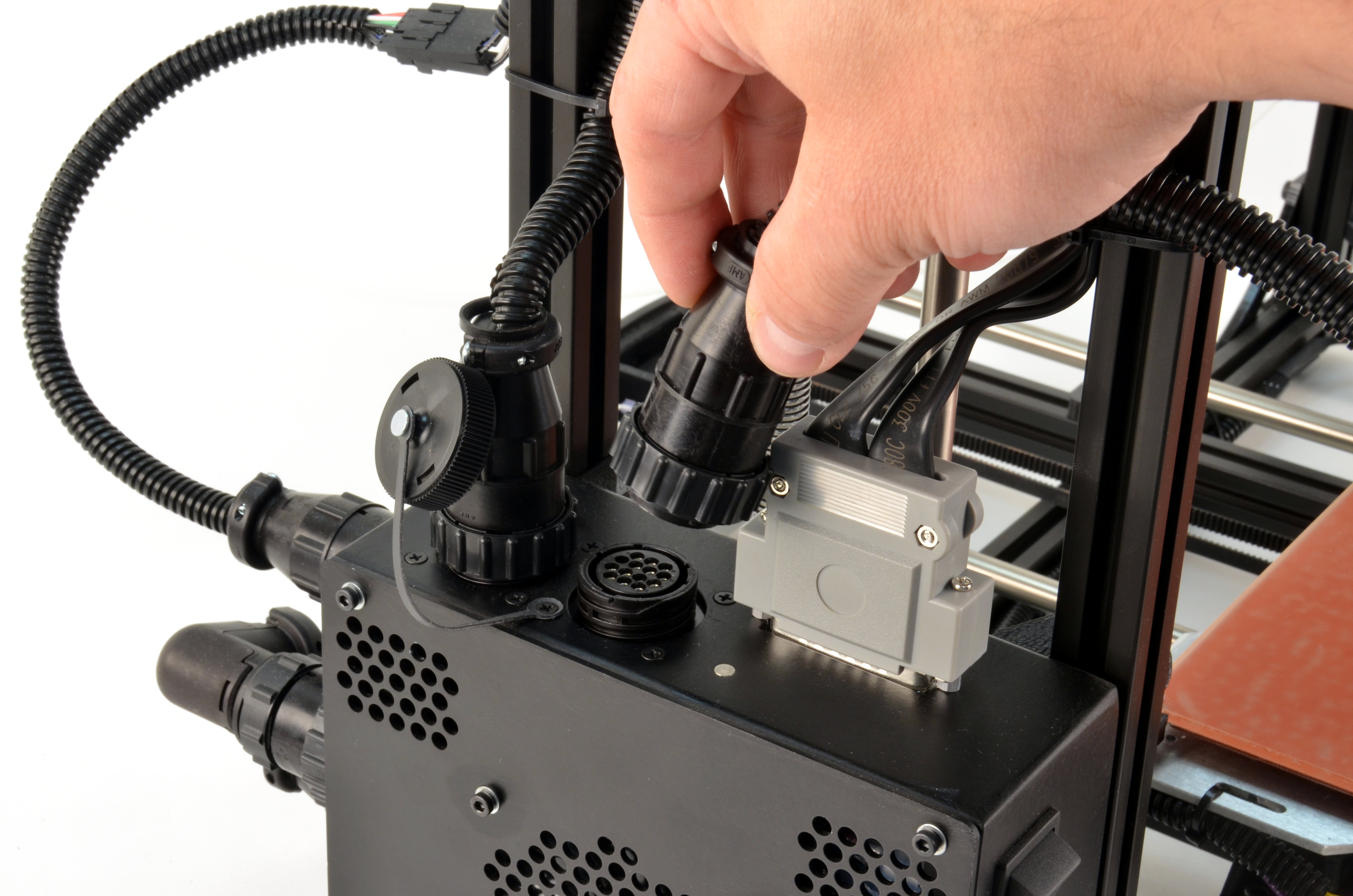
Unscrew the cap on the second port on top of the electronics box on your LulzBot TAZ 3D printer, then plug in the secondary extruder harness into the uncapped port.
9B
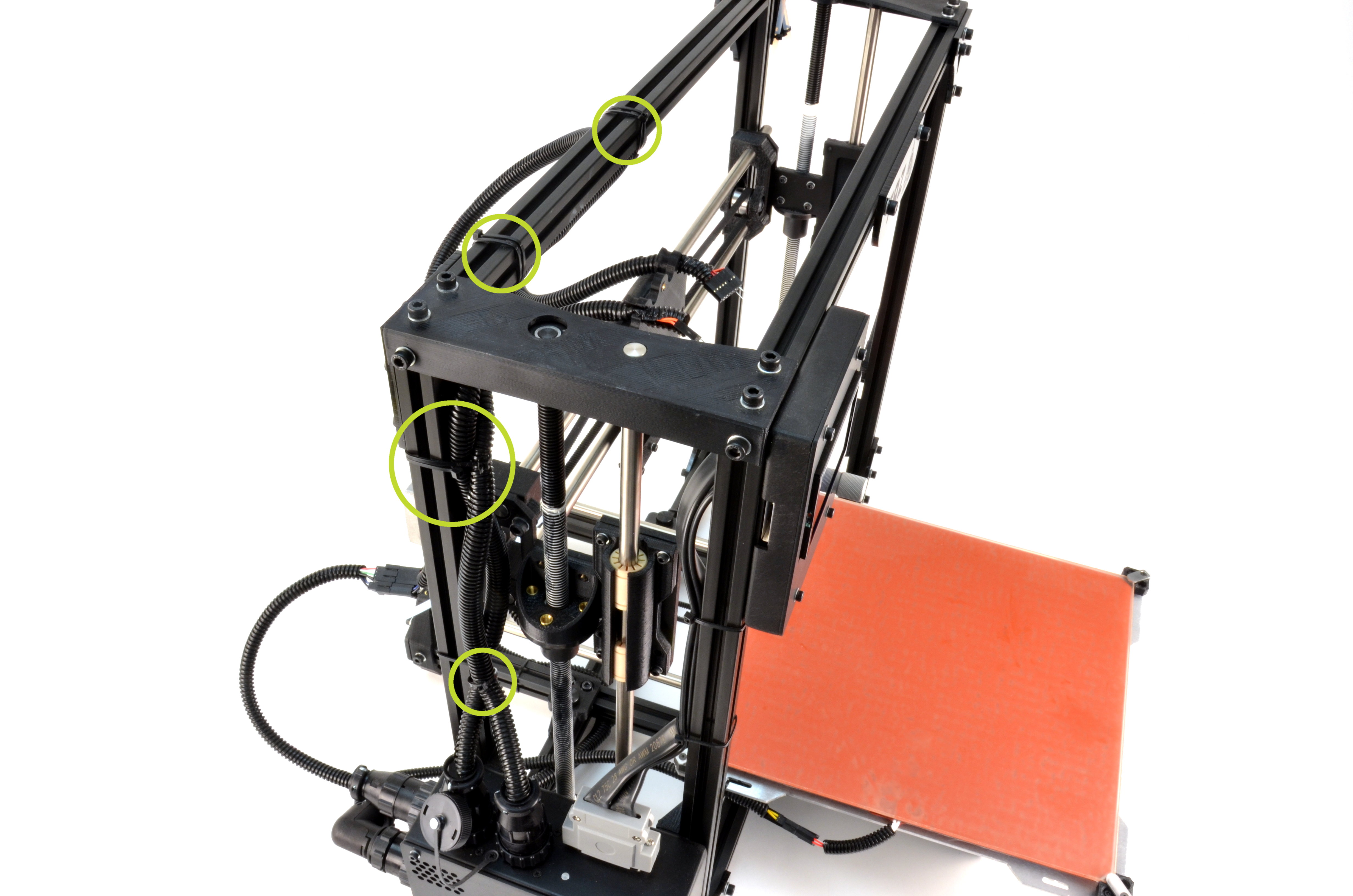
Route the new harness next to existing one on your printer, using zip ties to secure it in the same spots.
9C
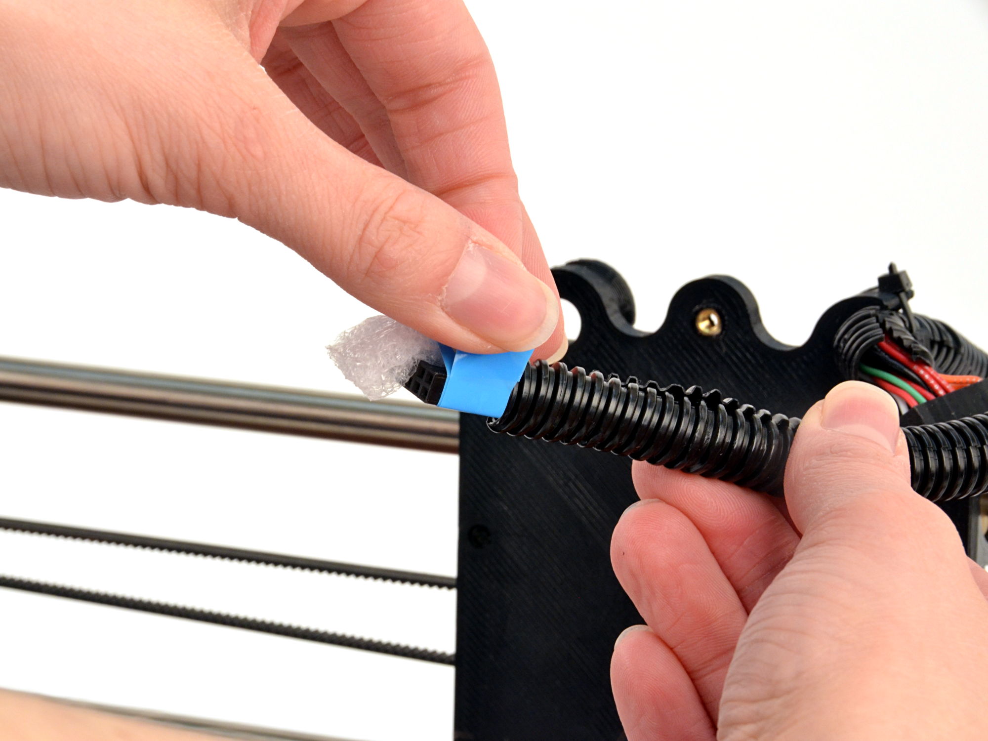
Unwrap the tape holding the protective foam off the end of the second extruder harness connector.
9D
Use a zip tie to secure the new secondary extruder harness into the empty harness holder on the top left side of the x-carriage.
10A
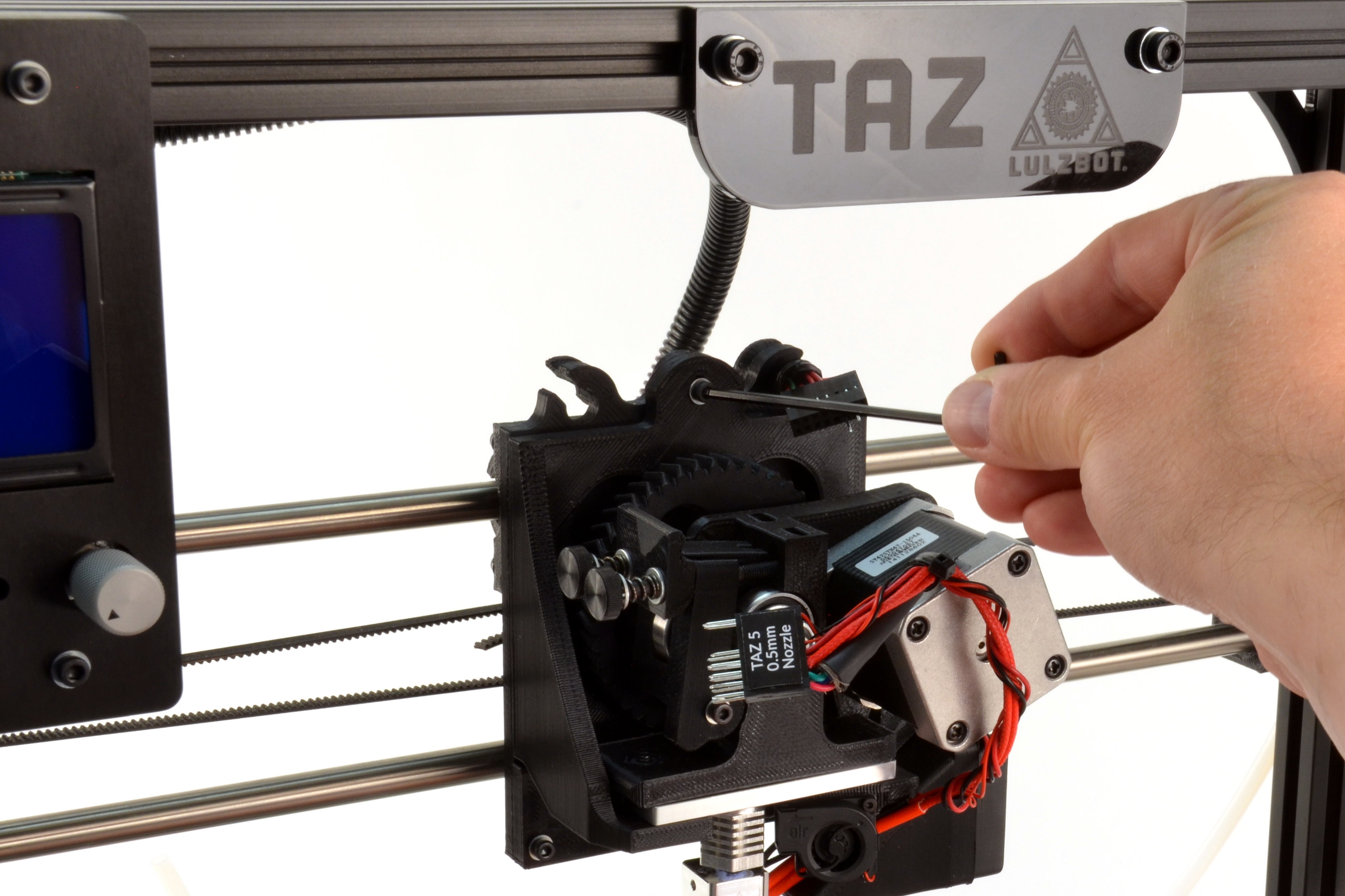
Unplug the connectors for your current tool head.
10B
With one hand support the tool head and unscrew the single M3 screw securing it to the X axis carriage.
10C
Remove the tool head from the 3D printer by lifting the tool head up.
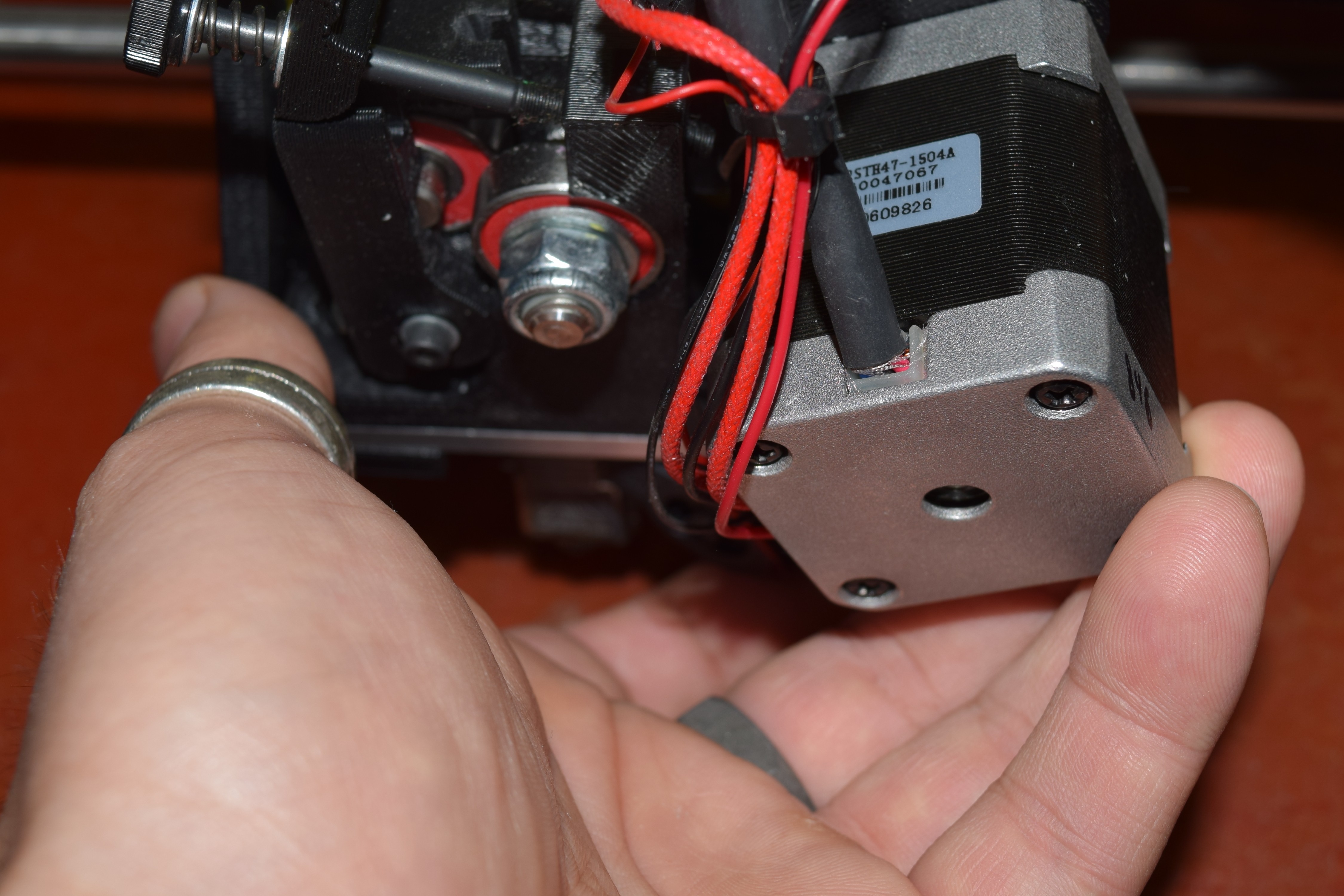
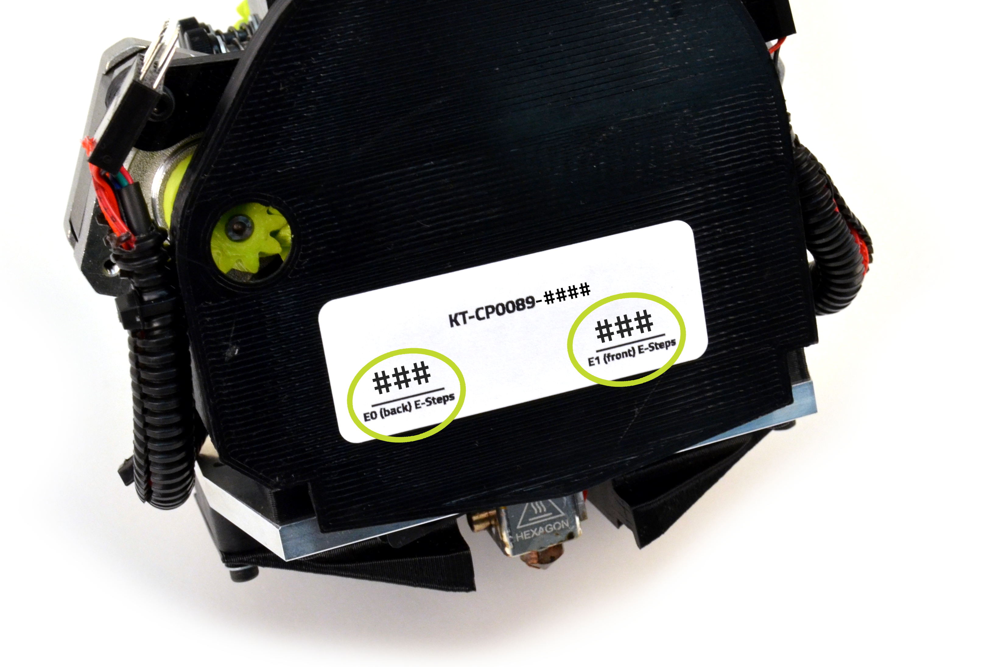
Your new tool head has 2 different Extruder Steps Per Unit (E steps) values. These two important new values can be found on a sticker on the back of the extruder.
11A
Record the first extruder (T0) E steps, and the second extruder (T1) E steps.
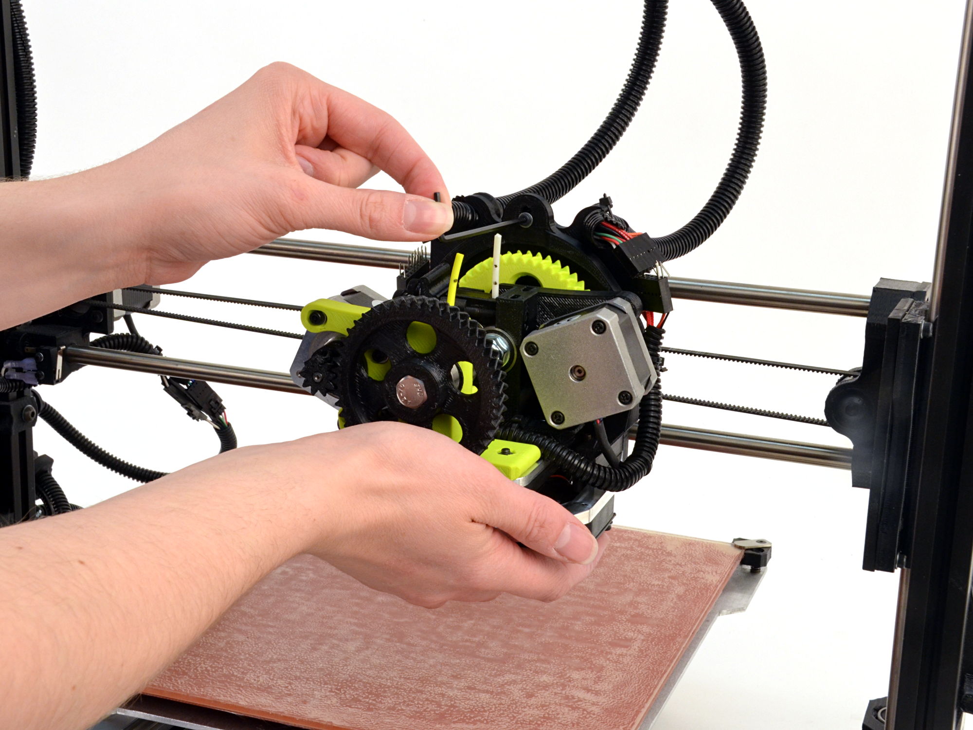
Install the tool head by seating it on the X axis carriage and secure it with the M3 screw that you removed in the previous steps.
13A
Connect the two 16 pin connectors, making sure to match them based on the pins in the connectors. Note: You may have one or two spare fan connectors that will not be used.
13B
Use zip ties to secure the second extruder harness to the 3D printer frame, following the existing wire harness.

14A
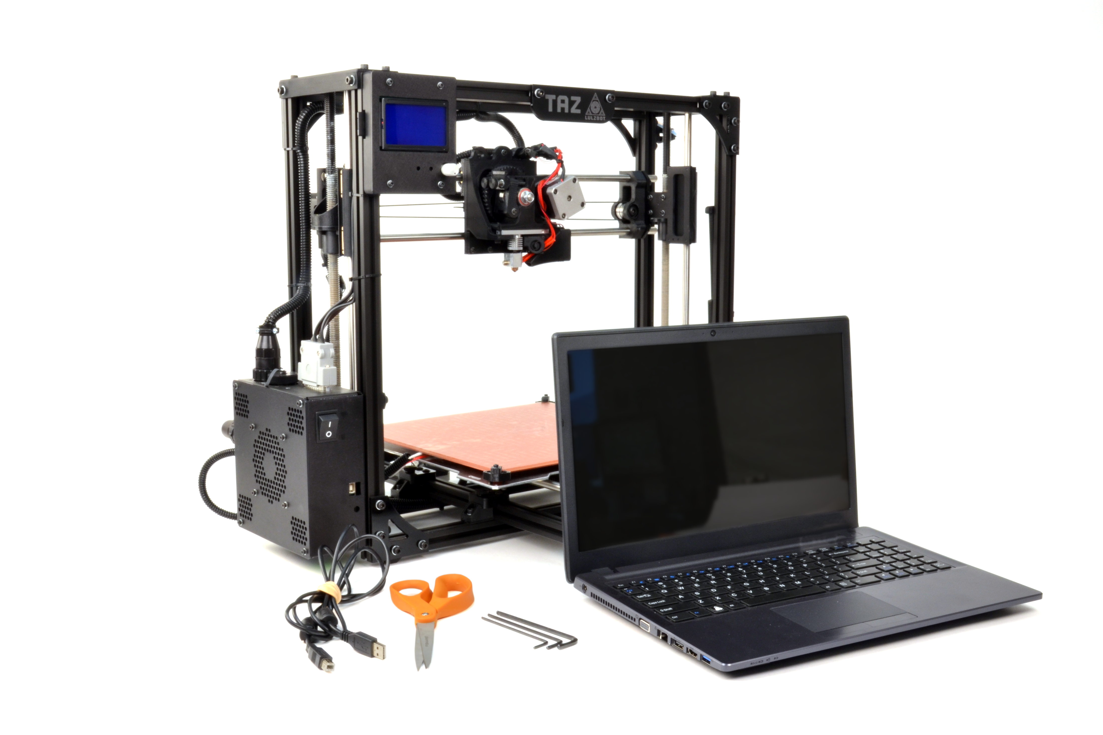
Install the latest version of Cura LulzBot Edition. It is important to have the LulzBot Edition of Cura, as it has preset machine configuration profiles built into it.
14B
Cura LulzBot Edition is available from http://LulzBot.com/Cura.
14C
Plug in your LulzBot TAZ 3D printer to the power supply and power on your 3D printer.
14D
Once powered on connect your 3D printer to your computer using the USB cable.
14E
Open Cura LulzBot Edition.

15A
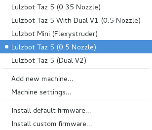
Select Machine > LulzBot TAZ 5
15B
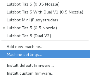
Select Machine > Machine Settings
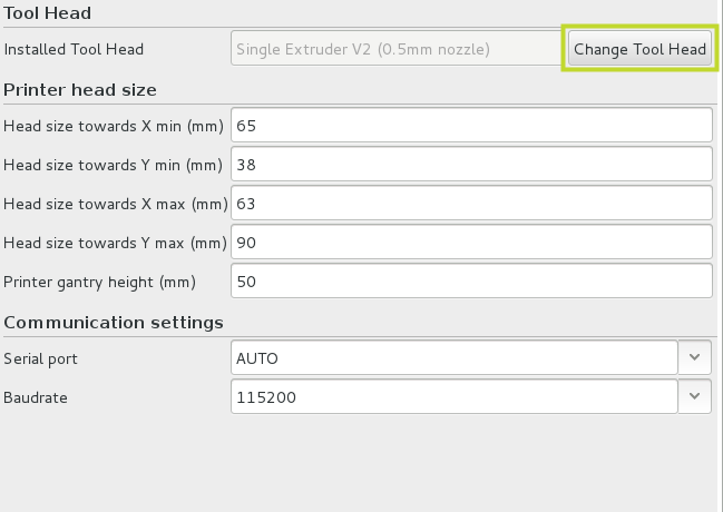
In the Machine settings window:
15C
Select Change Tool Head
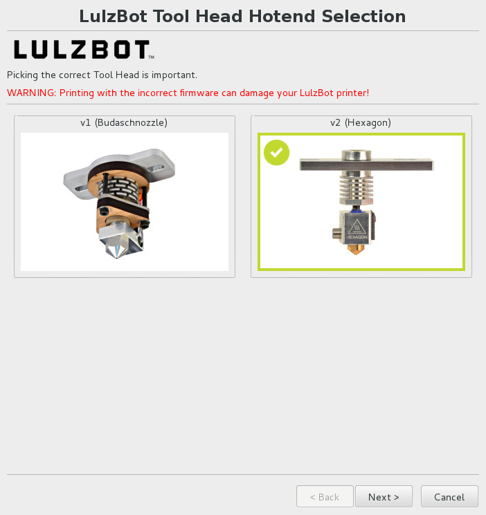
16A
Select v2 (Hexagon).
16B
Select FlexyDually v2.
16C
Select Next to continue.

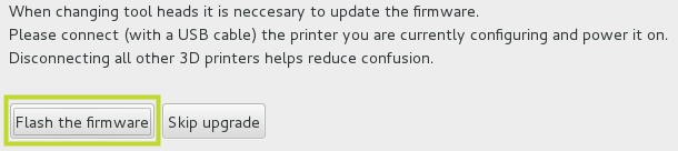
17A
Make sure your 3D printer is plugged into your computer through USB and that your 3D printer is powered on.
17B
Press the Flash the firmware button.
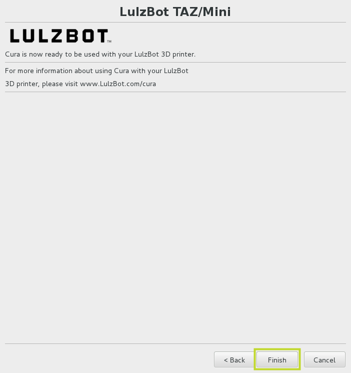
17C
Press the Finish button once the firmware update process has completed to exit the wizard.
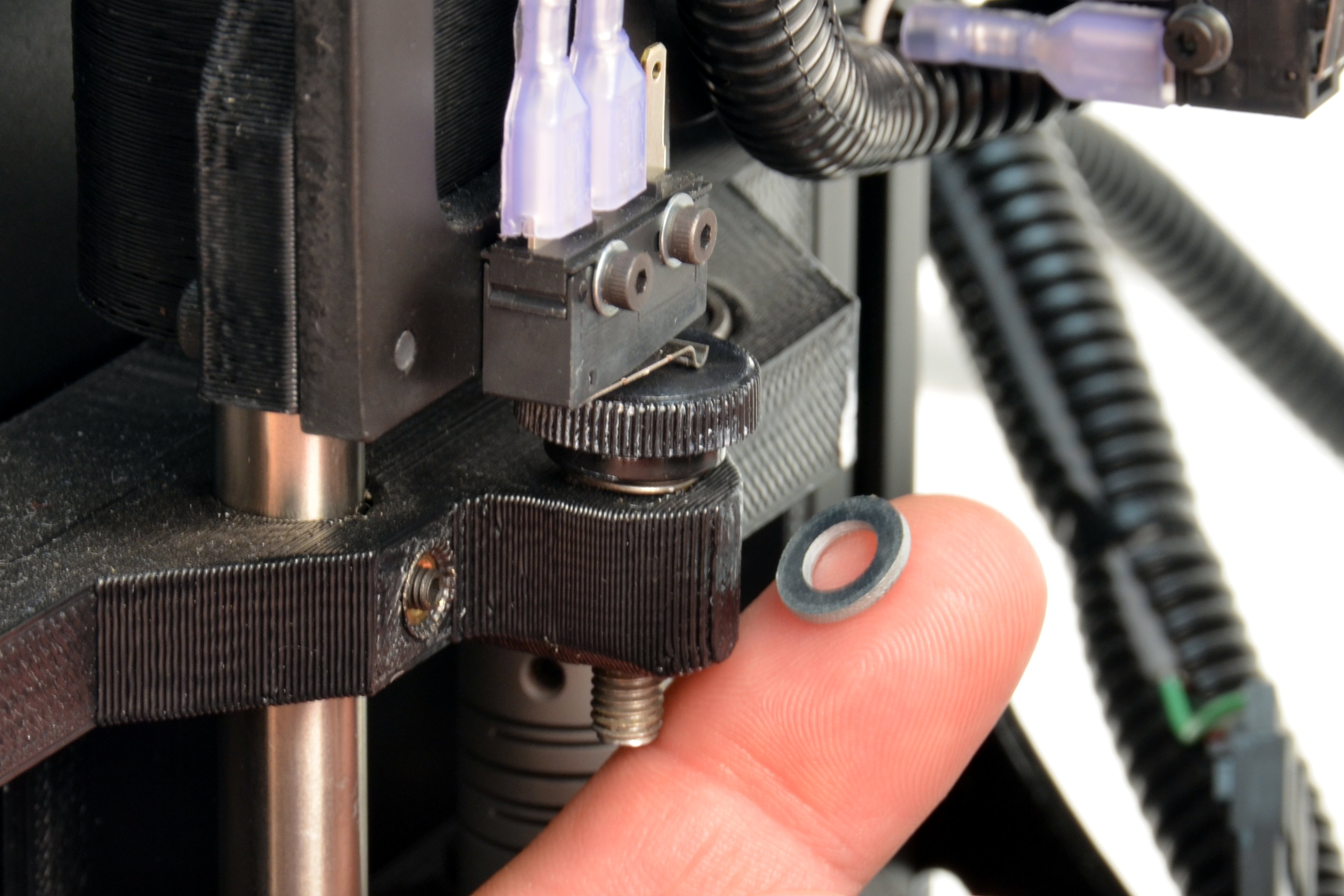
To prevent damage to your 3D printer, power it off immediately if the tool head looks like it is on a course to lower into the print surface before triggering the Z end stop.
If the tool head looks like it will prematurely trigger the Z end stop too high above the print bed, adjust the thumb screw lower and restart this process.
The spring and washer can be removed if needed to achieve the proper Z height.
Load the calibration models in the following order:
Press the Control button to open the Printer Interface window.
21A
Once the Printer Interface window opens, home the printer by pressing Home Z.
21B
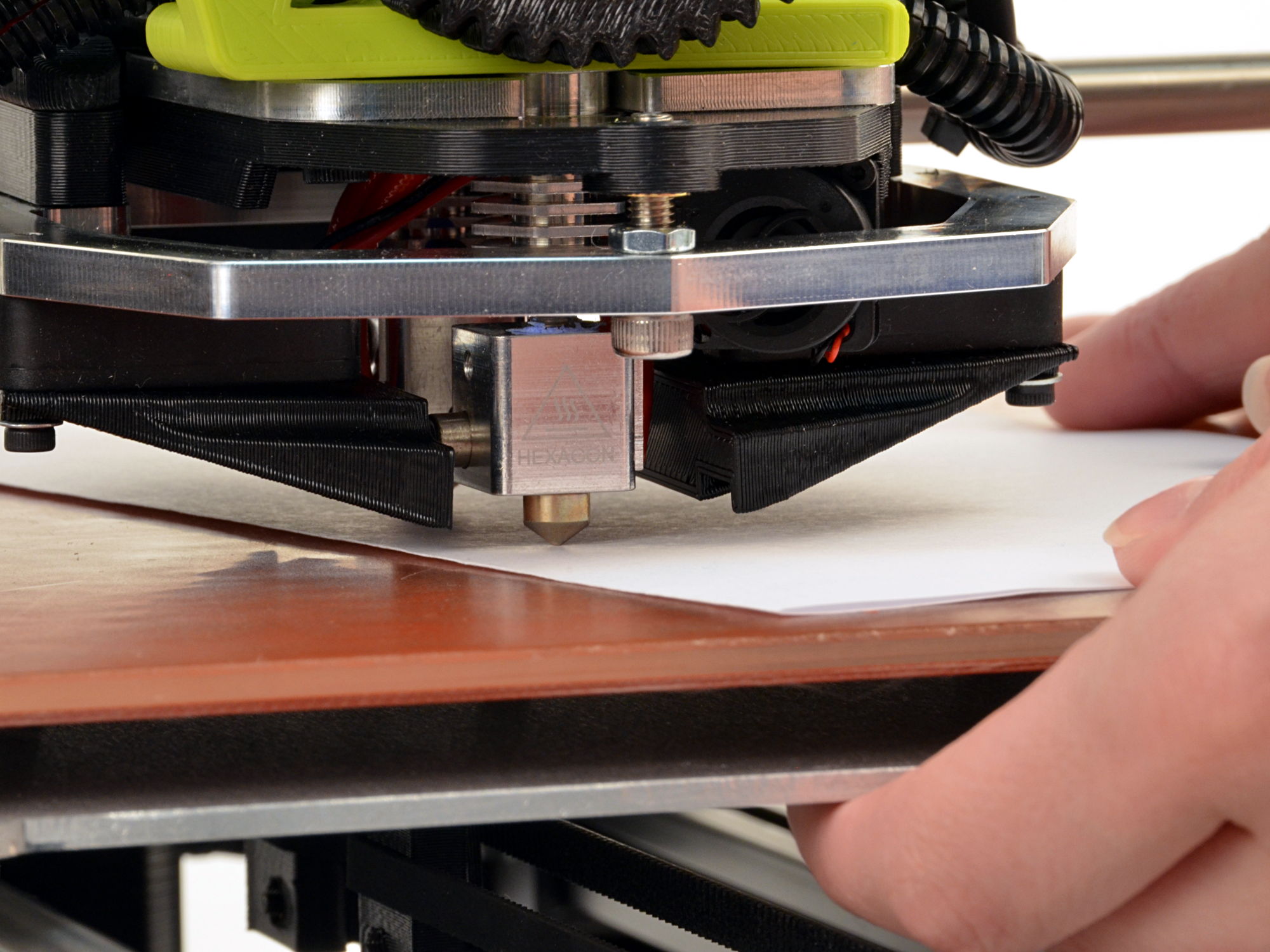
Adjust the homing height by repeatedly homing the Z axis and turning the Z axis end stop trigger until a sheet of paper folded in half just barely slides under the rear nozzle.
21C
To adjust the level of the T1 (front) extruder push the bed away to have access to the leveling screw. The leveling screw is found on the front dual extruder mount.
21D
Adjust it with the 4mm driver until the two nozzles are the same height above the bed. Turning the screw counter-clockwise raises the front nozzle. Turning the screw clockwise lowers the front nozzle.


22A
Home the printer again and check the level of each nozzle with the folded sheet of paper to make sure that the tension felt when moving the paper underneath each nozzle feels the same.
In order to get the best performance from your FlexyDually Tool Head v2 you will want to calibrate the following items:
Recommended Tools:
24A
Use the Graphical LCD controller to clear the EEPROM settings from the previous firmware.
24B
Navigate to: Configuration and select Restore Failsafe.
24C
Scroll up and select Advanced settings > Esteps/mm to update the extruder steps per unit (E-steps or esteps) to get the best performance from your FlexyDually Tool Head.
24D
Use the control knob on the Graphical LCD controller to adjust the value.
24E
Adjust the E2stps/mm value.
24F
Once set, back out of the menu entries until you can select Store Memory.
24G
Select Store Memory to save the adjusted Extruder Esteps/mm.

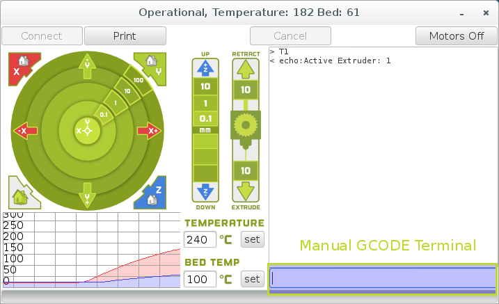
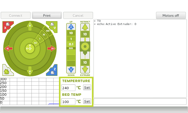
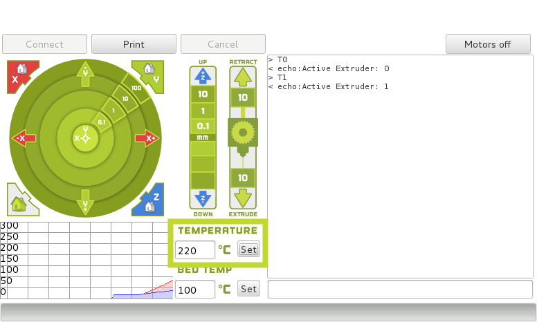
Use the terminal entry box in the lower right hand side of the control window to manually enter the GCODE commands.
25A
Set Extruder 0 (rear) as the active extruder:
T0
Press Enter on your keyboard to send the command.
25B
Set Extruder 0 (rear) hot end temperature to 240°C and the print surface to 100°C by using the Set buttons.
25C
Set extruder 1 (front) hot end as the active extruder:
T1
Press Enter on your keyboard to send the command.
25D
Set Extruder 1 (front) hot end temperature to 220°C by using the Set button.
25E
Set Extruder 0 (rear) as the active extruder:
T0


To determine the X and Y axis positioning adjustments needed, we will print the inner and outer square in the next step.
26A
Make sure that both hot ends are at the proper extrusion temperature and that the print surface is at its ideal temperature as well.
26B
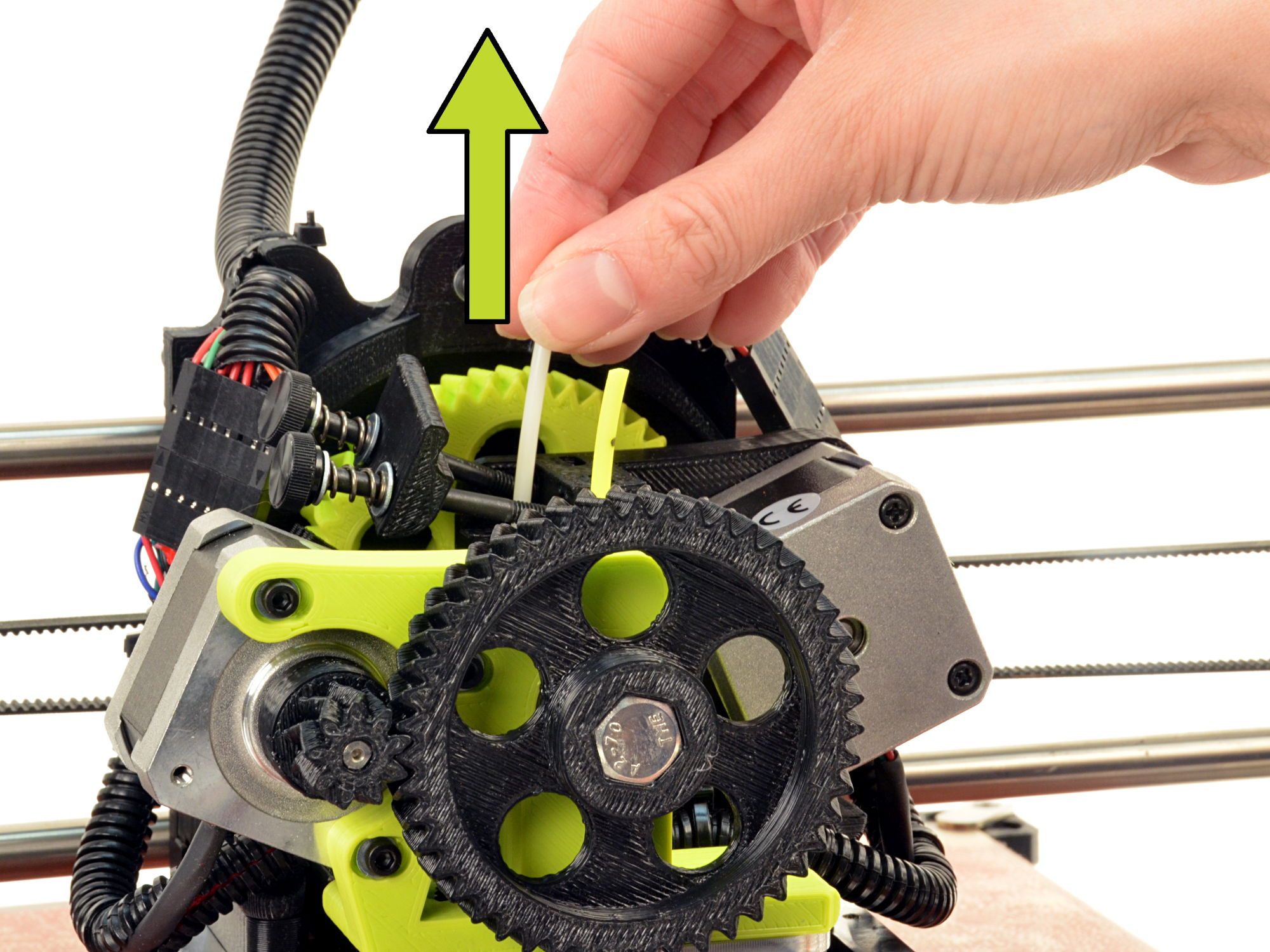
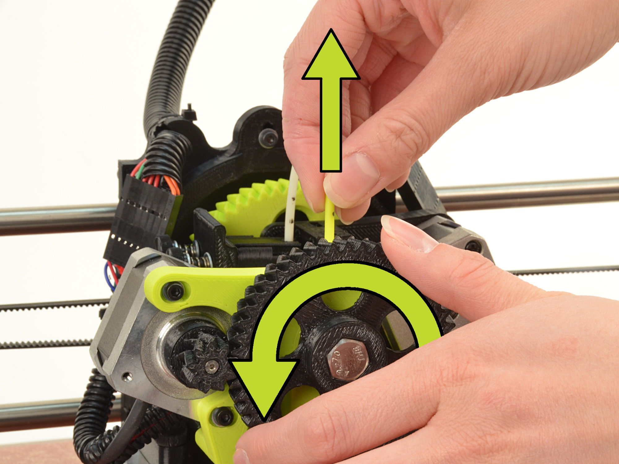
Remove the filament used during the factory calibration process.
26C
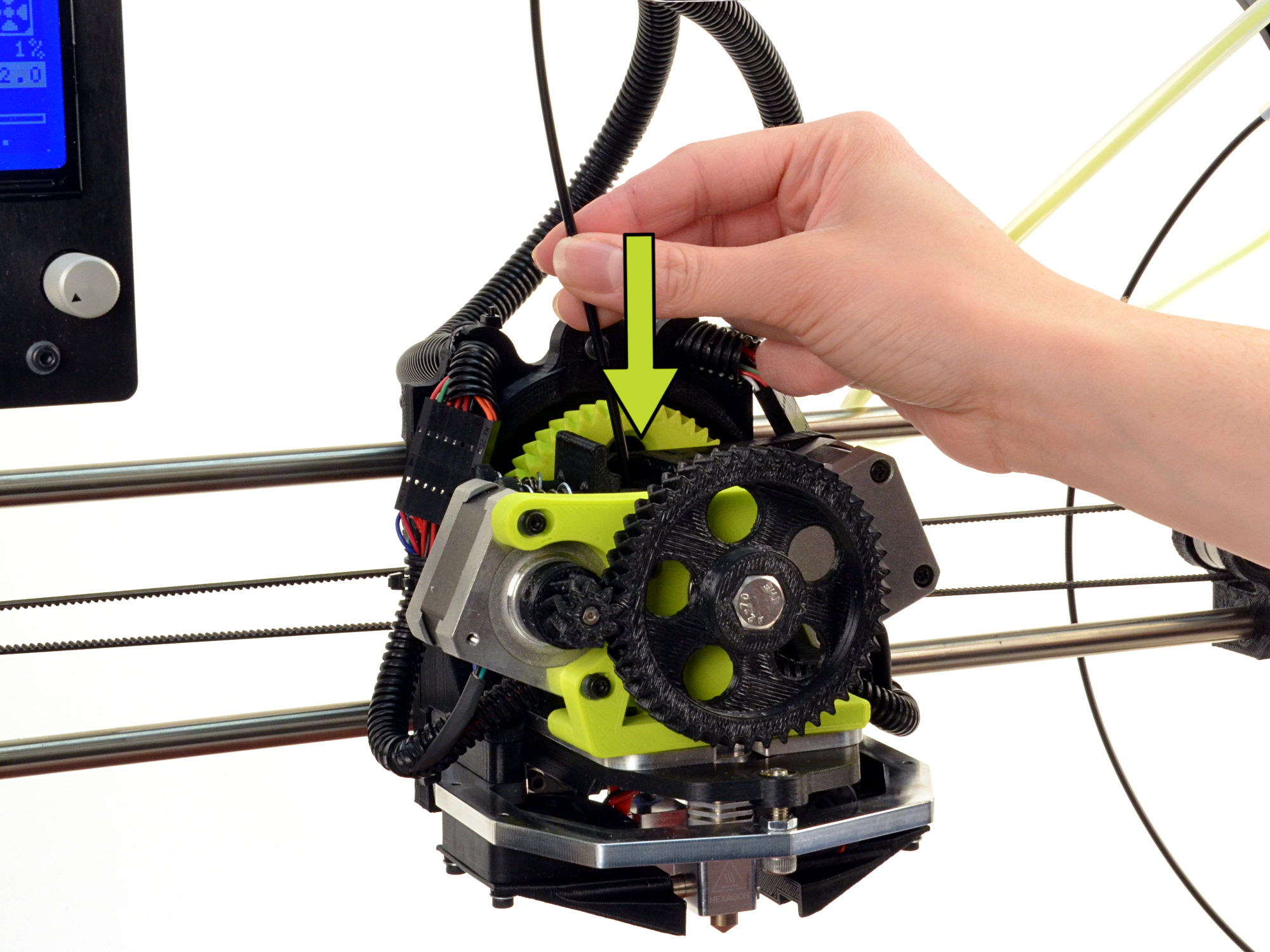
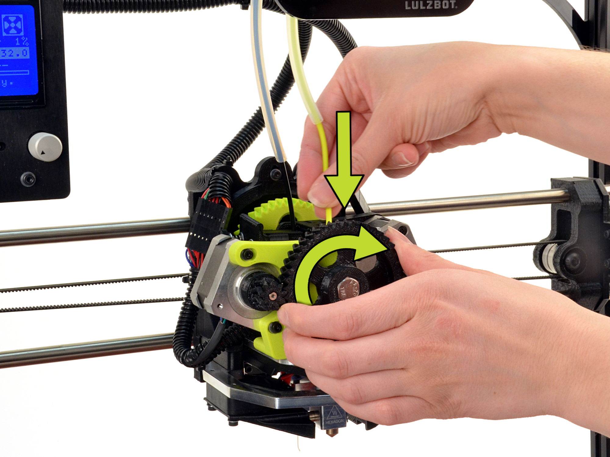
Load the filament samples into both extruders: ABS into the rear extruder and NinjaFlex into the front extruder.
26D
Purge the calibration filament by rotating each large gear by hand until the extruder transitions to the sample filament.
26E
Close the printer interface window.
27A
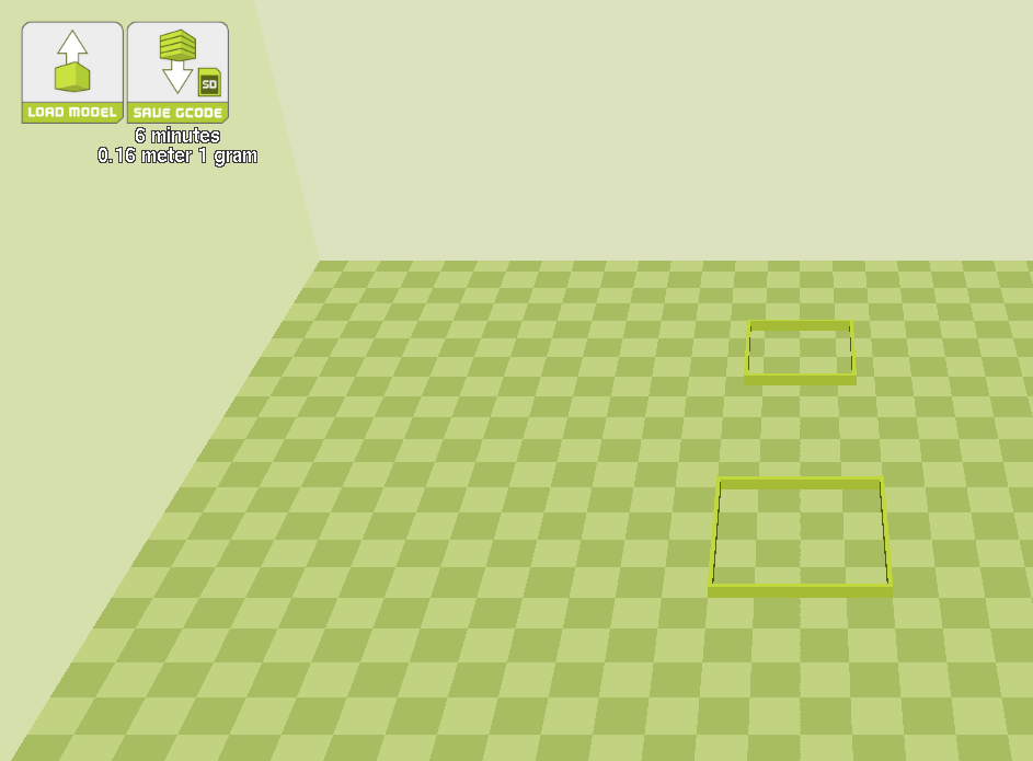
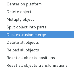
Left click on the smaller, inner square.
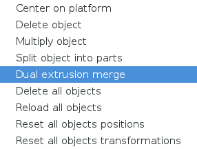
27B
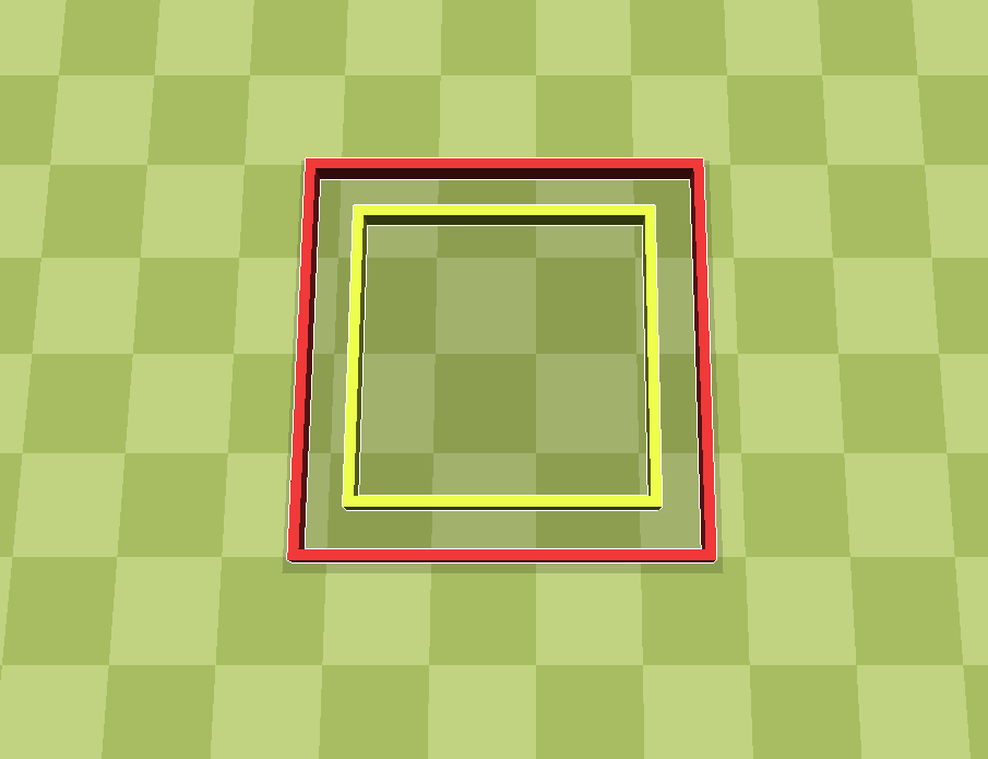
Right click on the smaller, inner square and select dual extrusion merge.
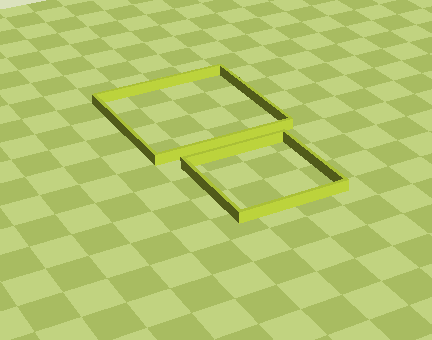
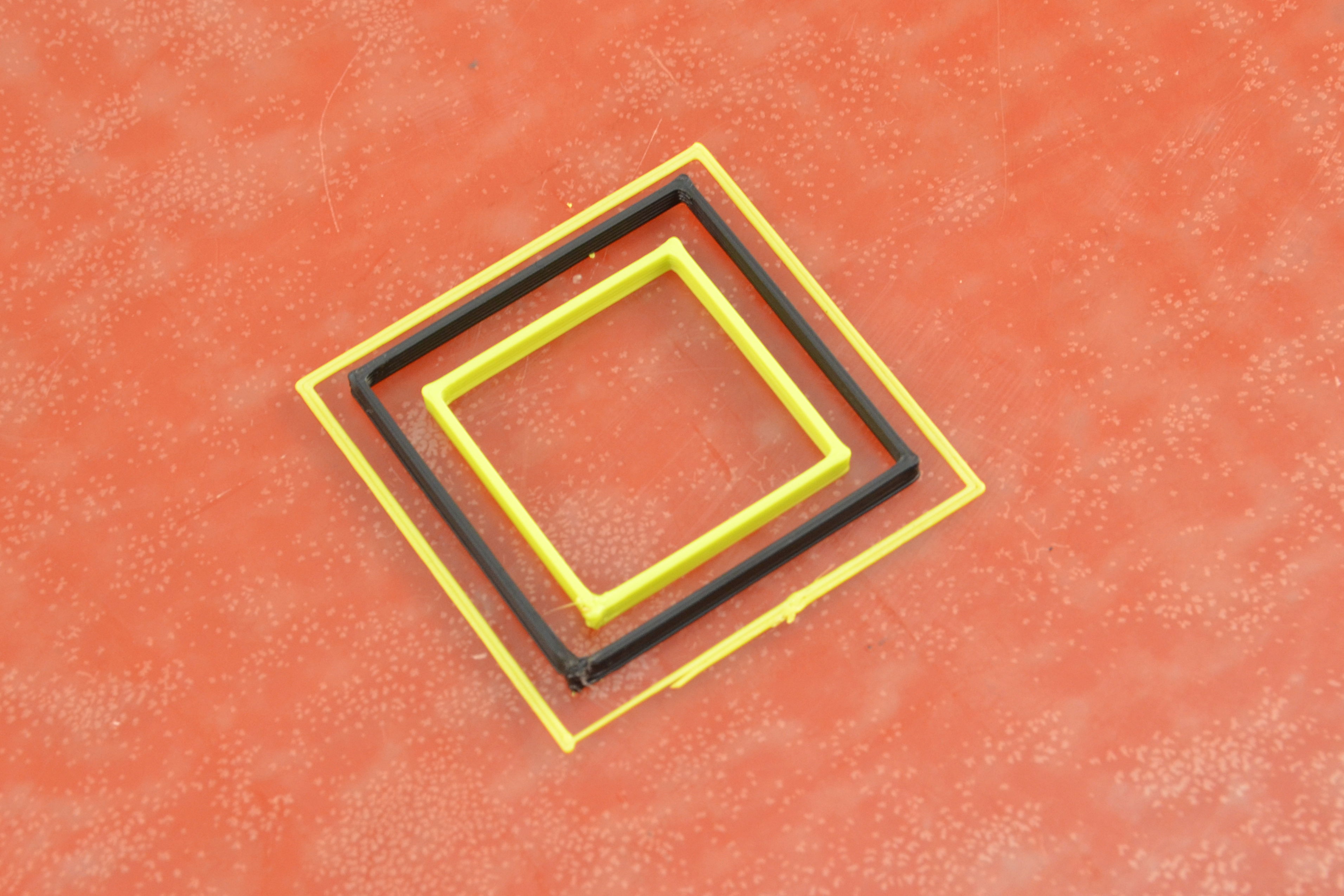
Your merged calibration squares should have the same color and positioning as the sample image

28A
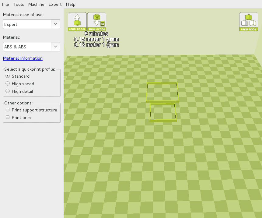
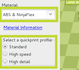
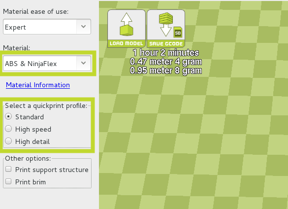
Select your material (ABS & NinjaFlex), and the Standard print profile.
28B
Switch to Full settings mode by selecting Expert > Switch to full settings.
28C
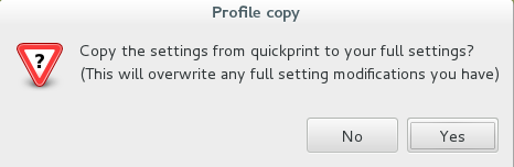
Copy existing settings
28D
Under the Basic tab turn off:
Wipe&prime tower
Ooze shield


29A
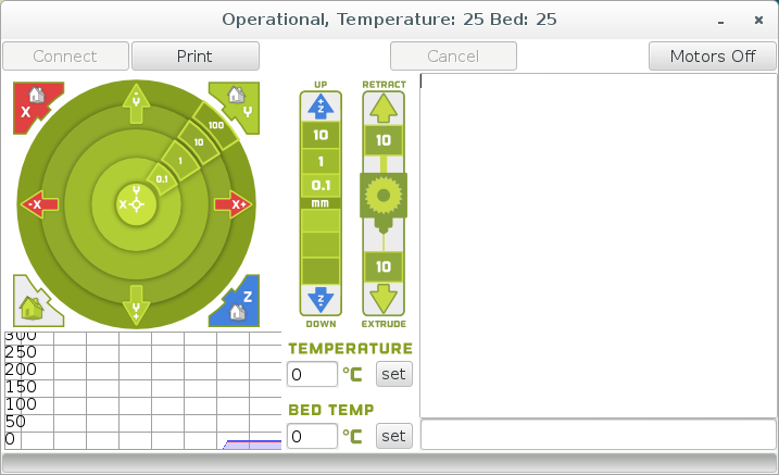
Press the Control button to open the printer interface window.
The top of the Printer Interface window will display the current printer status.
It will display: Opening, followed by: Connecting, and finally: Operational.
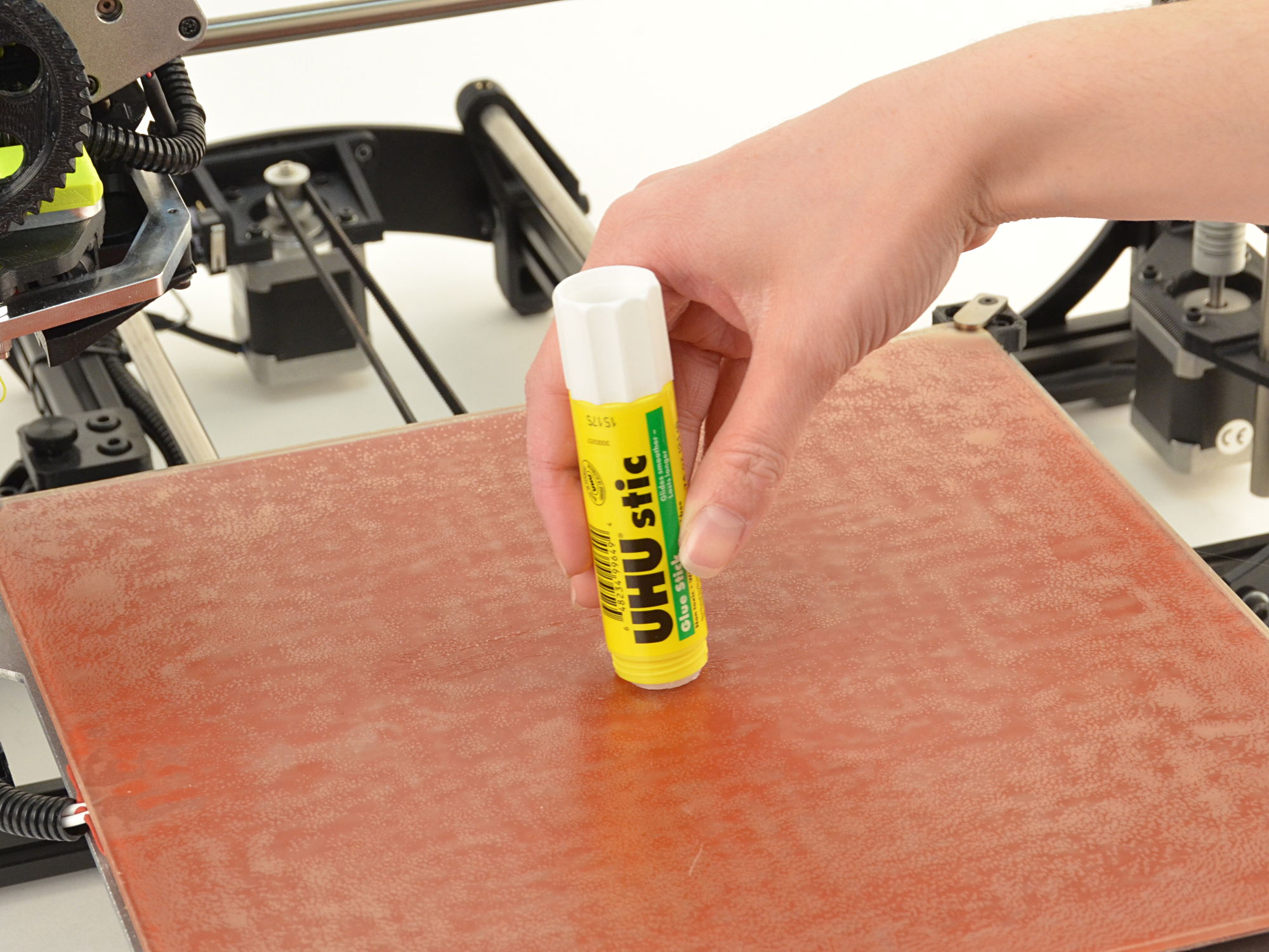
29B
Since NinjaFlex adheres to the PEI print surface exceedingly well, sparingly apply the PVA-based glue stick (included) to the print surface.
Use the terminal entry box in the lower right hand side of the control window to manually enter the GCODE commands.
30A
Set Extruder 0 (rear) as the active extruder:
T0
Press Enter on your keyboard to send the command.
30B Set Extruder 0 (rear) hot end extrusion temperature to 240°C and the print surface to 100°C by using the Set buttons.
Use the terminal entry box in the lower right hand side of the control window to manually enter the GCODE commands.
31A Set extruder 1 (front) hot end as the active extruder:
T1
Press Enter on your keyboard to send the command.
31B Set Extruder 1 (front) hot end extrusion temperature to 220°C by using the Set button.
31C Set Extruder 0 (rear) hot end as active:
T0
Press Enter on your keyboard to send the command.
Press Print to print the calibration squares.
As the print progresses, the prime tower, and the ooze shield will print around the calibration squares, and within the inner calibration square.
After the print completes, remove the prime tower and the ooze shields.
28A
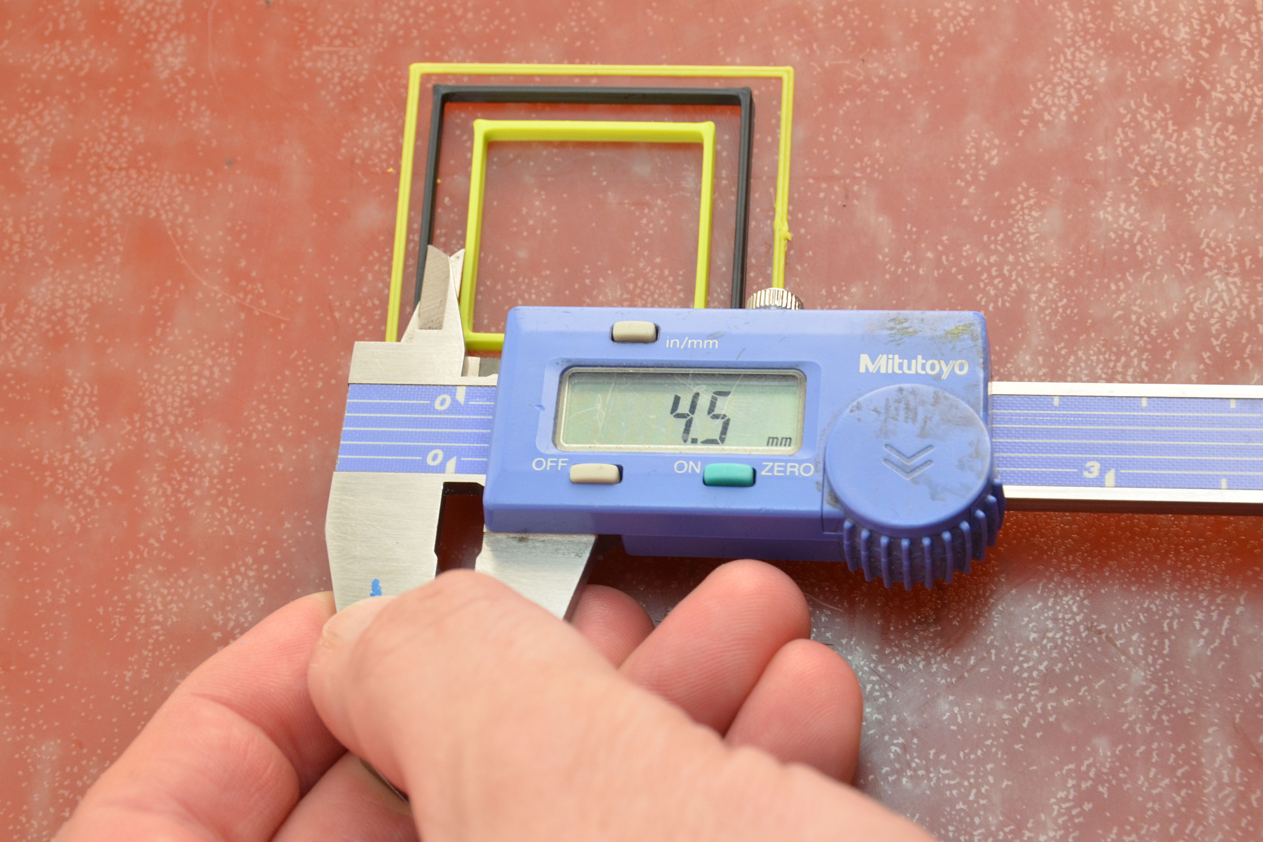
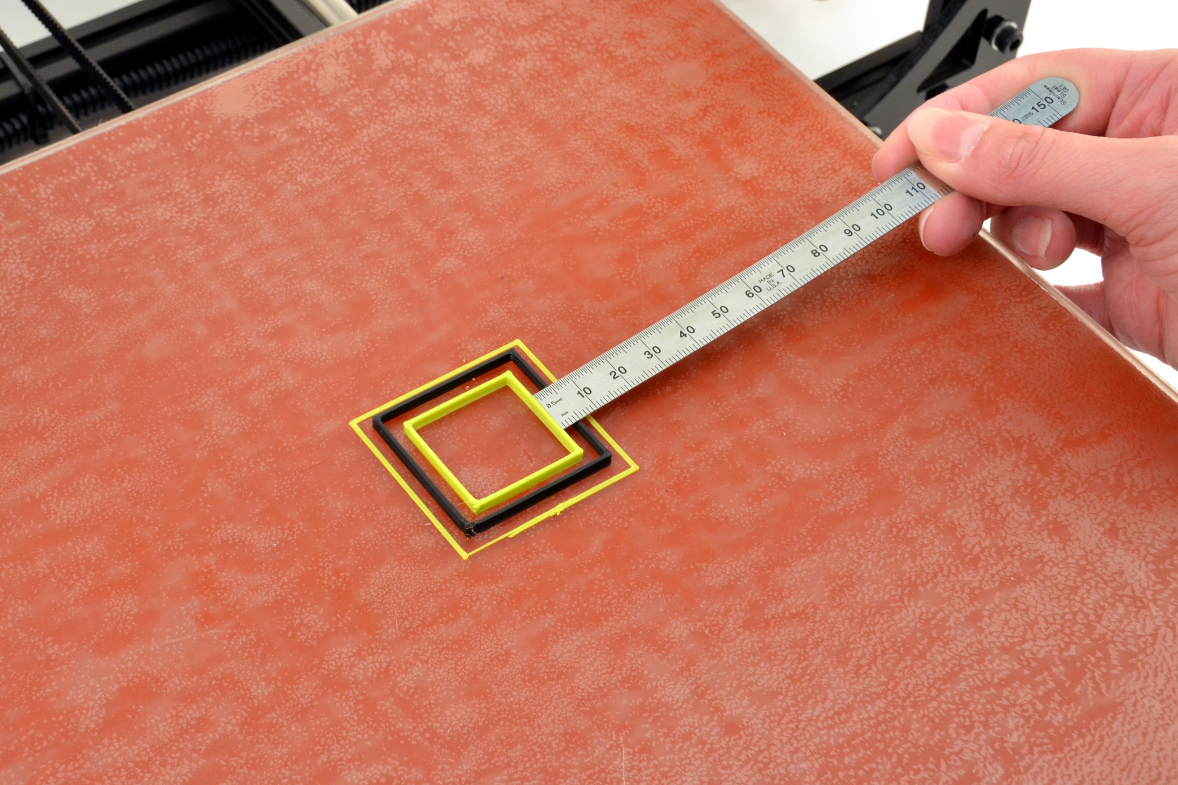
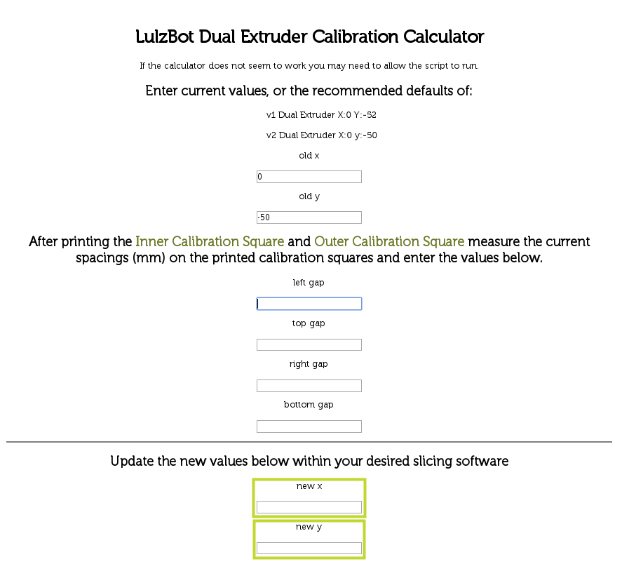
Use your digital calipers or ruler to measure the gap between each model from the top & bottom, and the gap between each side.
28B
Record your current values.
29A
Enter these numbers into our offset calculator found here:
https://www.lulzbot.com/dual-extruder-calibration-calculator
29B
This will produce new offsets, that will need to be updated in the Machine Settings menu. Note the new values.
29C
Close the printer interface window.
30A
Open the Machine settings window by selecting:
30B
Machine > Machine Settings
30C
Update your__X__ and Y offsets and save the changes by pressing OK.

Reprint the inner and outer calibration squares using the previous steps to fine tune the offsets until you are satisfied with the results:


Remember:
The rear extruder is Extruder 0. The front extruder is Extruder 1.
The command T0 switches to the rear Extruder 0.
The command T1 switches to the front Extruder 1.
The order that you import STL files into Cura LulzBot Edition matters. For dual color or multi-material parts, import the part that you want printed with Extruder 0 (rear) first, then the part for Extruder 1 (front) second.

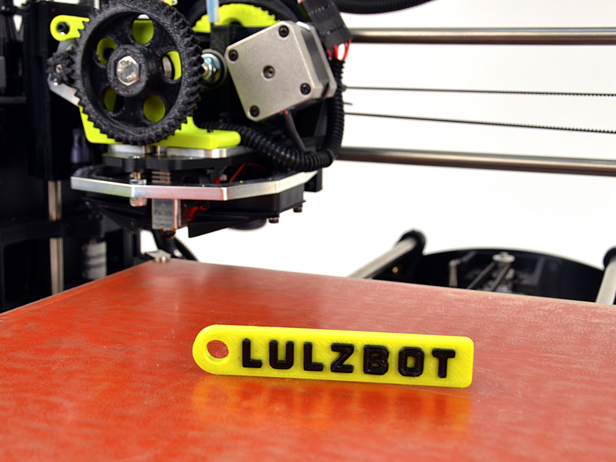
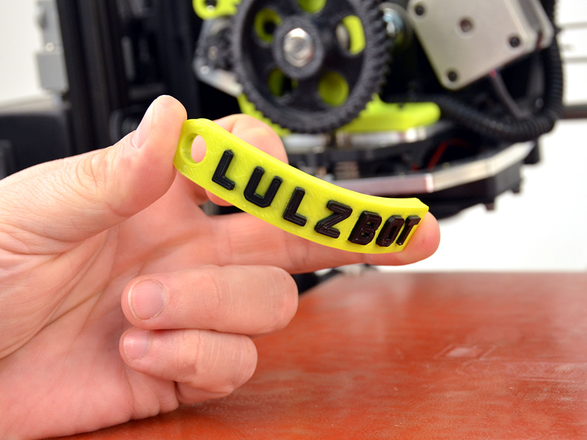
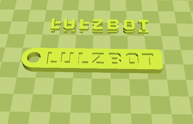
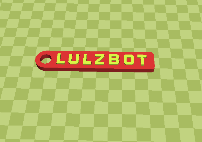
We will be printing a two colored keychain!
33A
Download the following 2 models:
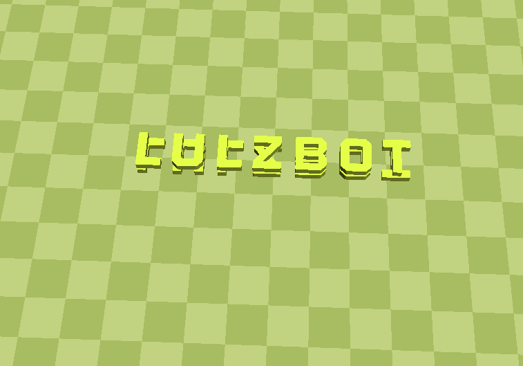
34A
In Cura LulzBot Edition, press Load Model and select lulzbot_taz_flexydually_keychain_text.stl.
The model should now be displayed on the virtual print surface.
34B
Press Load Model again and select lulzbot_taz_flexydually_keychain_body.stl.
The model should now be displayed on the virtual print surface next to the other model.

35A
Left click on the key chain body model. Doing this establishes that this portion of the final merged model will be printed with flexible filament in the front (T1) extruder .
35B
Right click on the keychain text model to be printed with the T0 (rear) extruder and select Dual Extrusion Merge.
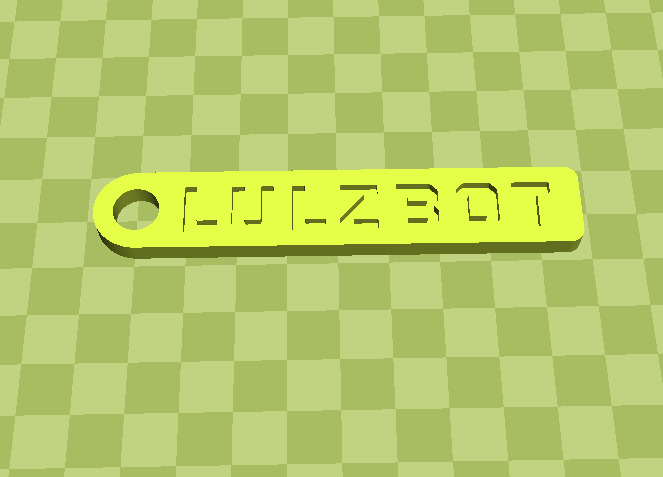
35C
The models will merge together. Your virtual print surface should look similar to the final image.
Remember:
36A
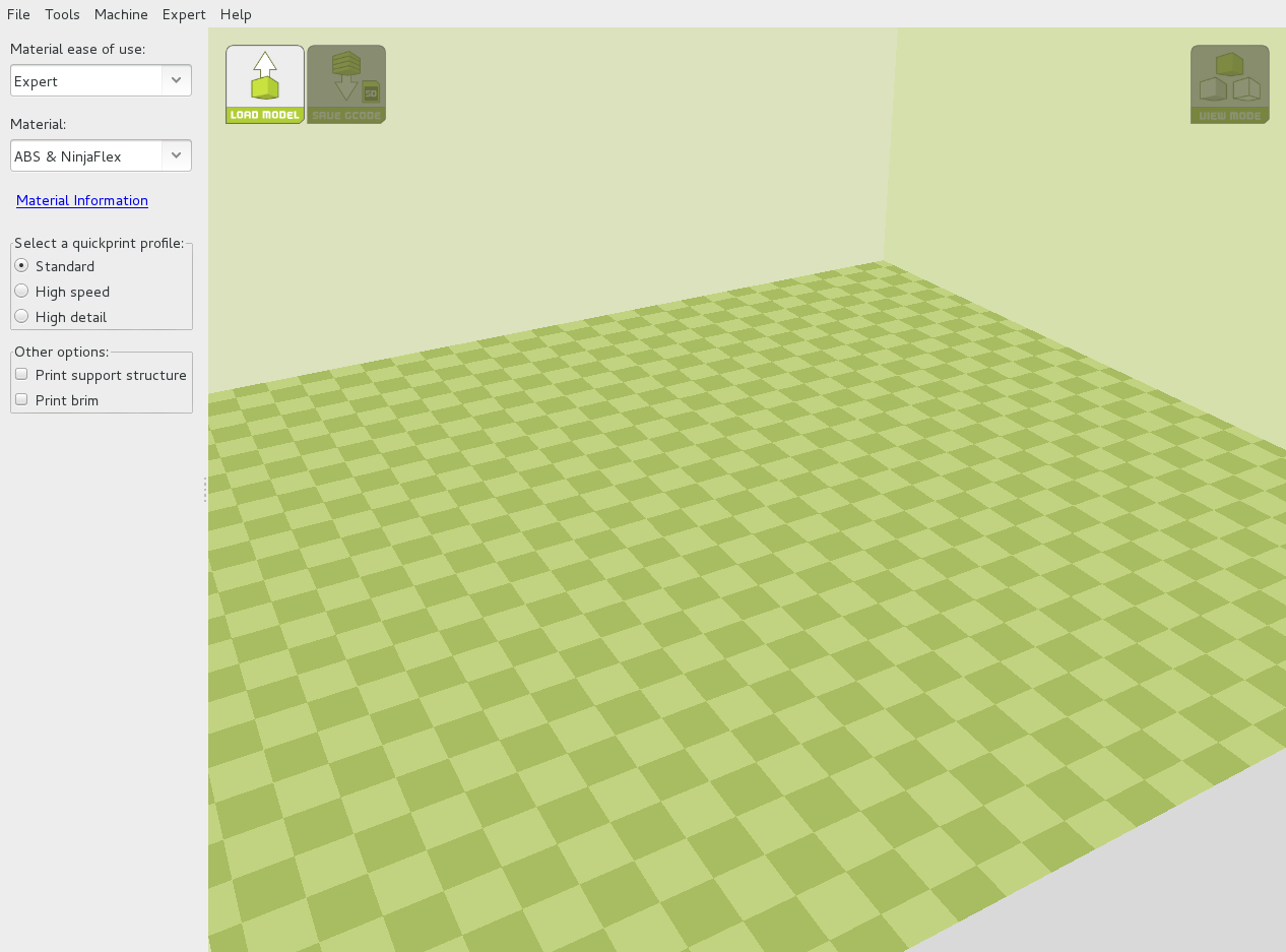
Switch back to quickprint mode by selecting: Expert > Switch to quickprint.
36B
Under Material select ABS & NinjaFlex.
36C
Choose the Standard quickprint profile.

37A
Press the Control button to open the Printer Interface window.
The top of the Printer Interface window will display the current printer status.
It will display: Opening, followed by: Connecting, and finally: Operational.
37B
Since NinjaFlex adheres to the PEI print surface exceedingly well, sparingly apply the PVA-based glue stick (included) to the print surface.


Use the terminal entry box in the lower right hand side of the control window to manually enter the GCODE commands.
38A
Set Extruder 0 (rear) as the active extruder:
T0
Press Enter on your keyboard to send the command.
38B
Set Extruder 0 (rear) hot end extrusion temperature to 240°C and the print surface to 100°C by using the Set buttons.

Use the terminal entry box in the lower right hand side of the control window to manually enter the GCODE commands.
39A
Set extruder 1 (front) hot end as the active extruder:
T1
Press Enter on your keyboard to send the command.
39B
Set Extruder 1 (front) hot end extrusion temperature to 220°C by using the Set button.
39C
Set Extruder 0 (rear) hot end as active:
T0
Press Enter on your keyboard to send the command.

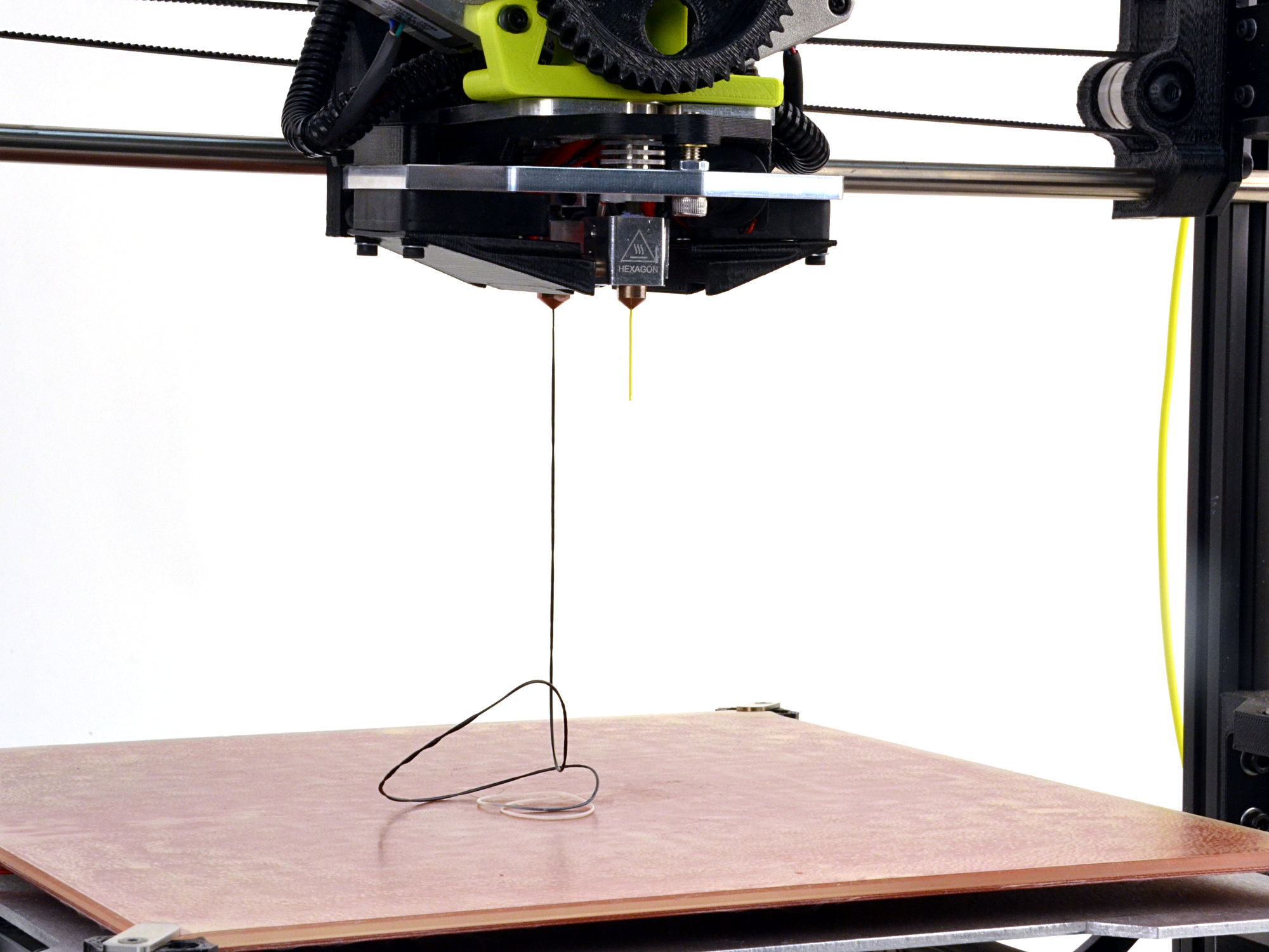
If you notice filament collecting under the hot end nozzles use tweezers to remove the plastic. Be careful as it will be hot.
40A
Once the printer has come up to the proper printing temperature for your filament, press Print!
40B
Your LulzBot TAZ 3D printer will start printing the skirt around your printed object. As the print progresses the extruder will automatically switch between tool heads throughout the printing process.

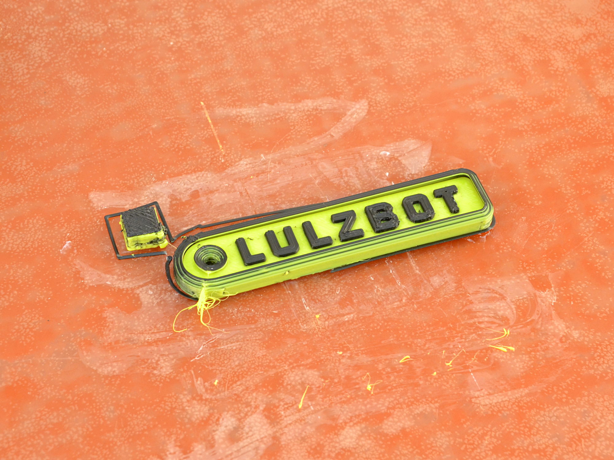
41A
Once the print has finished remove the ooze shield and wiping tower from the print surface.
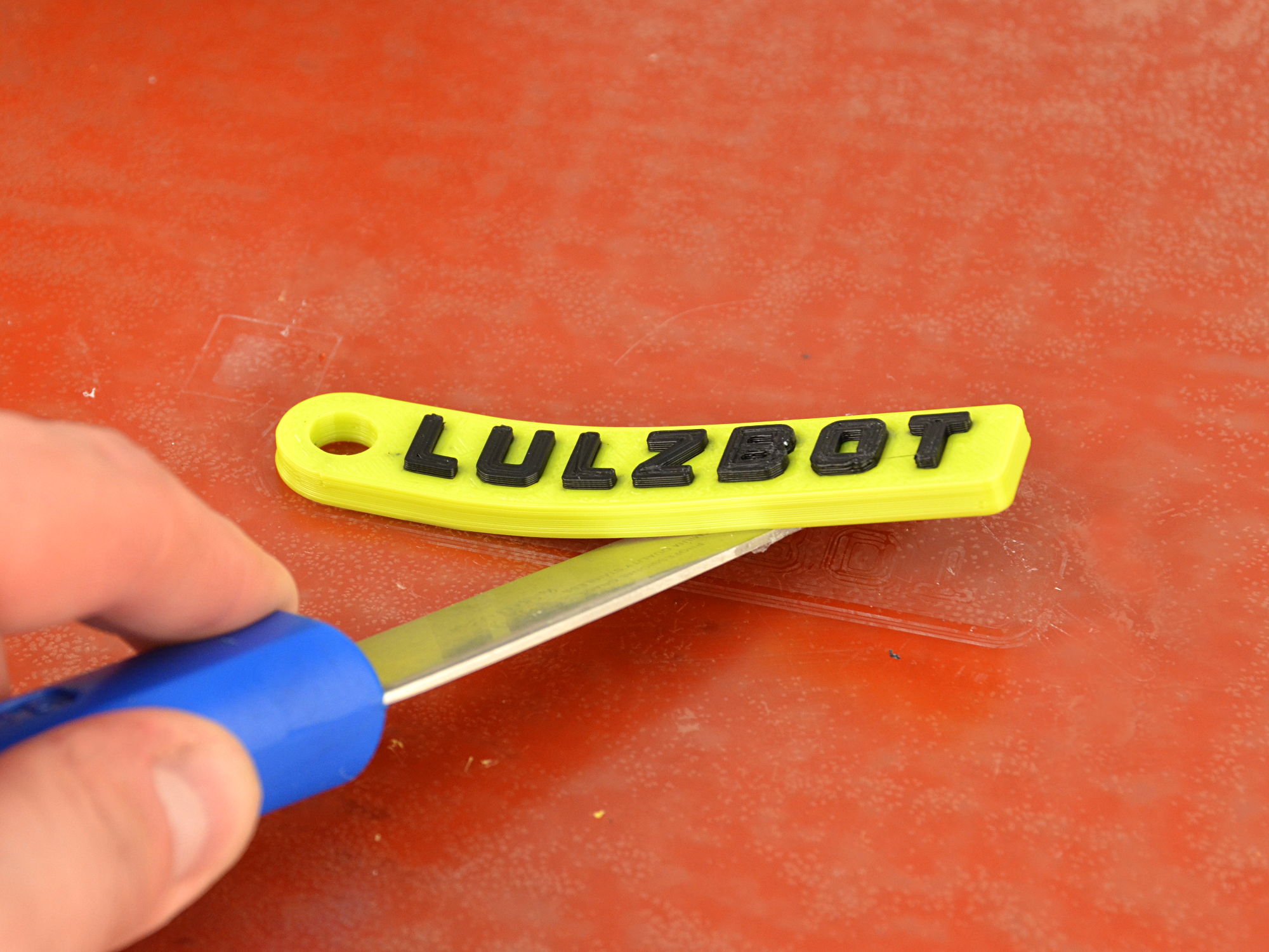
42B
Use the blue handled part removal tool to lift the key chain from the print surface.
42C
Peel off your key chain
Have questions, or ideas? Share them with your fellow LulzBot 3D printer users by joining our user forum at Forum.LulzBot.com