Open HardwareAssembly Instructions
Guides for installation and assembly of the LulzBot line of products made by FAME 3D LLC.
Guides for installation and assembly of the LulzBot line of products made by FAME 3D LLC.
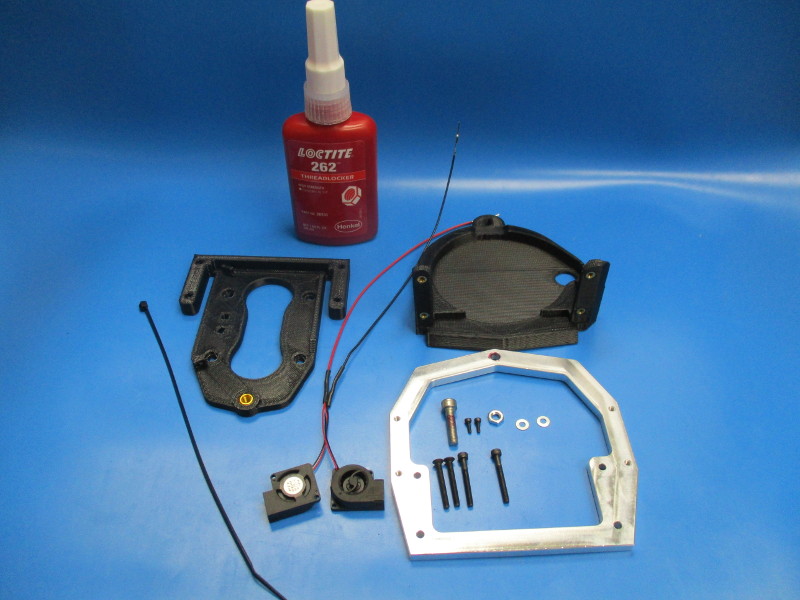
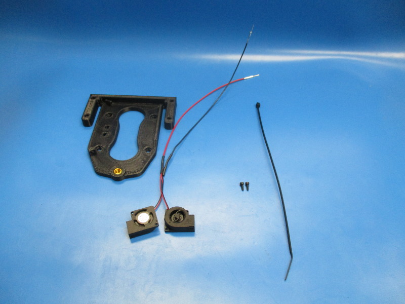
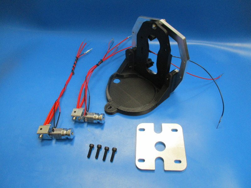
Gather parts
1x- Flex plate
1x- Dual extruder mount
1x- Micro blower harness
1x- cable tie (HD-MS0058)
1x- Lower bracket (PP-MP0086)
2x- M3x25 SHCS (HD-BT0041)
2x- M3x25 FHCS (HD-BT0135)
2x- M2x6 SHCS (HD-MS0230)
2x- M3 washer (HD-WA0001)
1x- M5x20 SS SHCS (HD-BT0153)
1x- M5 jam nut (HD-NT0016)
Locktite 262 (TL-CS0107)
Tools needed:
4.5mm hex driver
1.5mm hex driver
2.5mm hex driver
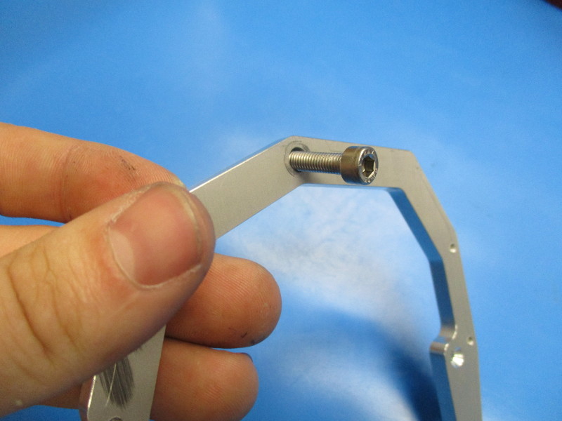
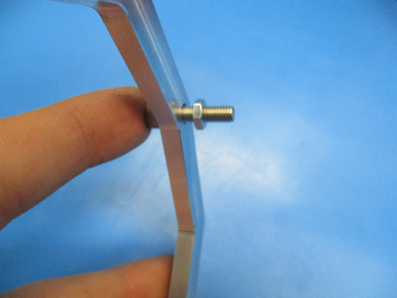
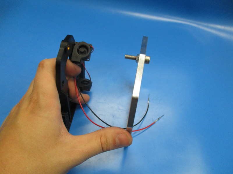
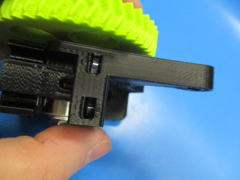
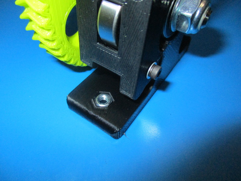
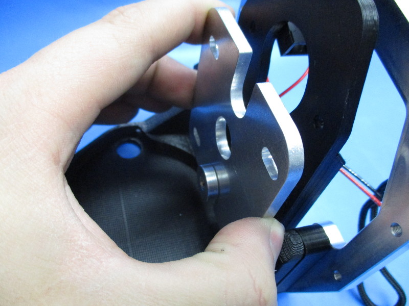
Insert the M5x20 SHCS into the lower bracket. (see image “Counter sunk holes” for part orientation)
Thread the M5 jam nut onto the M5 screw until there is a 5mm gap between the nut and the bracket.
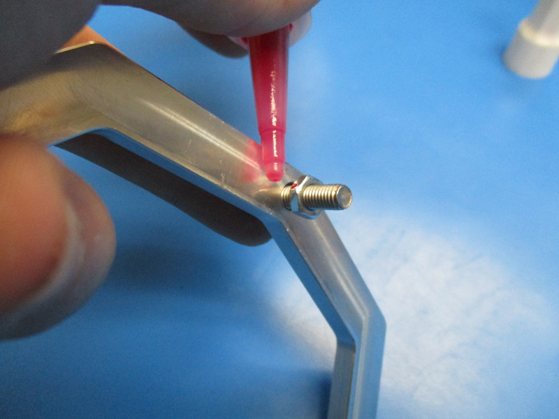
Apply locktite into the 5mm gap on the threads.
Finger tighten the nut up against the mount plate. You should be able to spin the screw with some resistance.


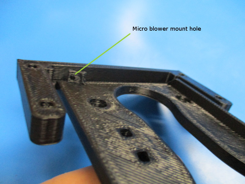
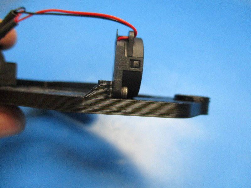
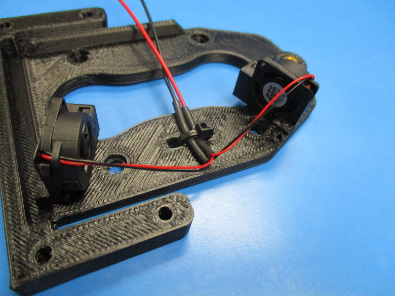
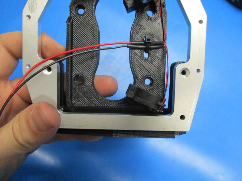
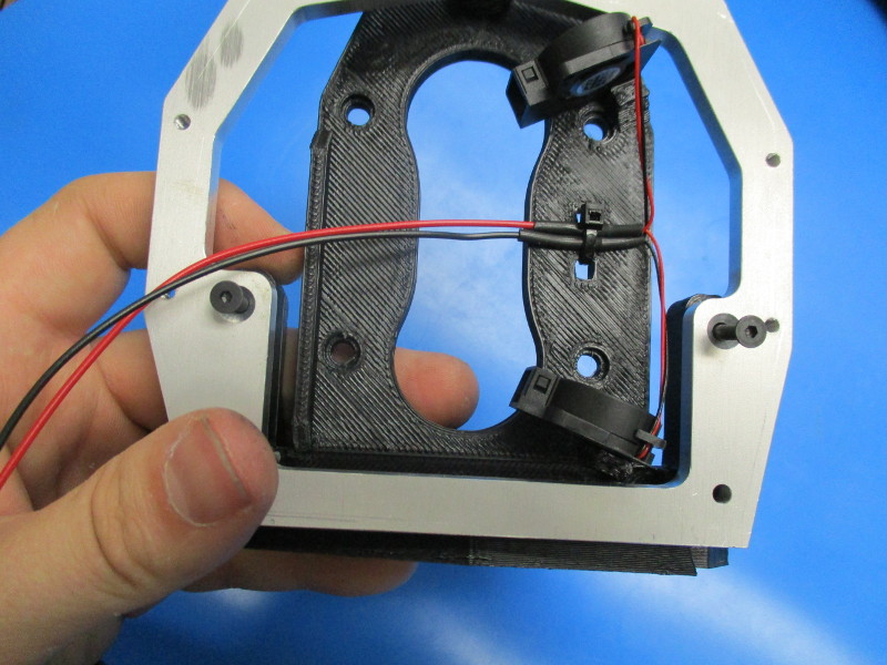
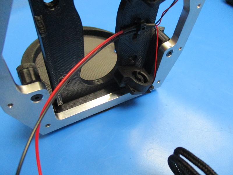
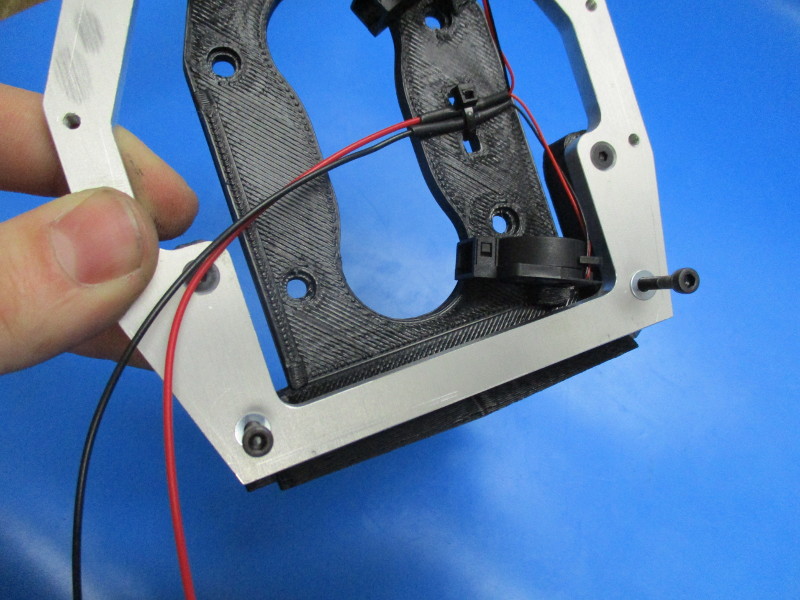
Locate the micro blower mount holes (see image “ Rear micro blower mount” and “forward micro blower mount” for location.
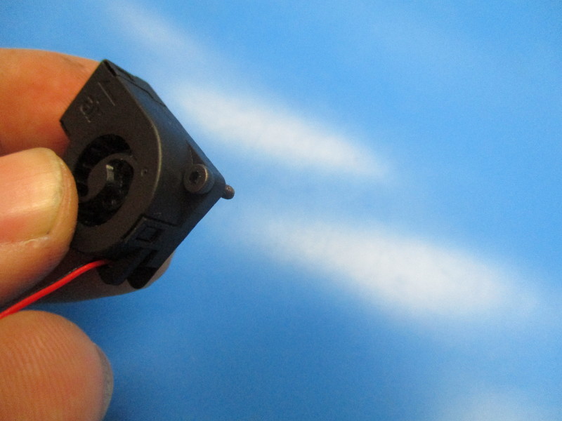
Insert a M2x6 screw into the mount hole on the micro blower (see image “M2 in micro blower” screw location)
Mount the micro blower on the rear micro blower mount. Finger tighten.
Repeat the process with the forward micro blower mount.
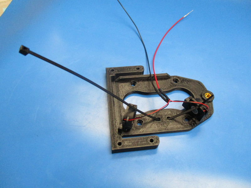
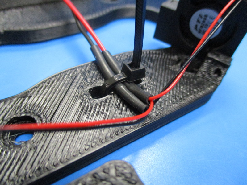
Fasten the harness to the flex plate using a cable tie. Feed the cable tie into the square holes in between the micro blowers. Tighten the cable tie around the ferrule in the heat shrink. Clip the excess cable tie.


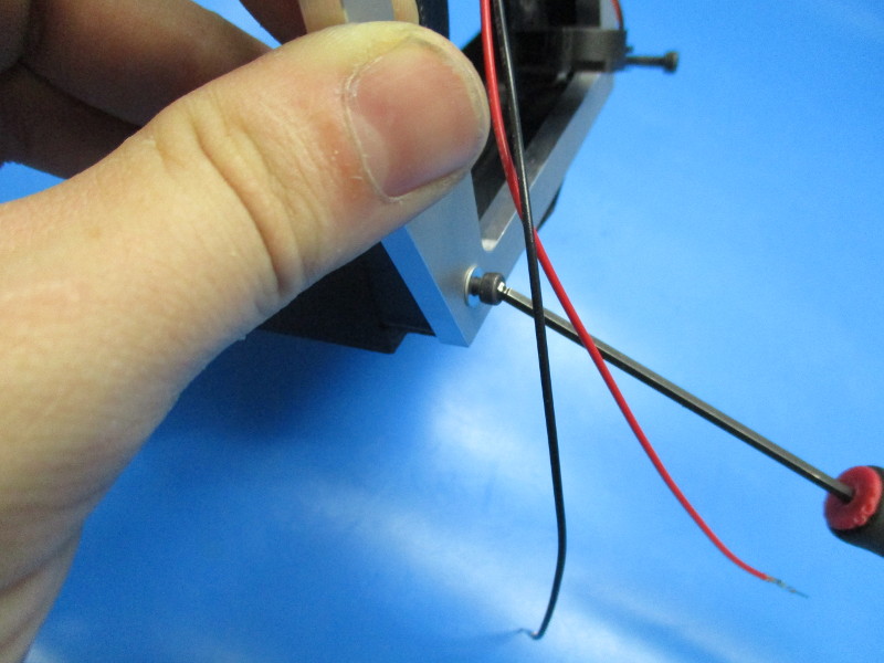
Align the M5 screw with the M5 threaded insert
Thread the screw into the threaded insert. Leave a 5mm gap between the flex plate and the nut on the screw.
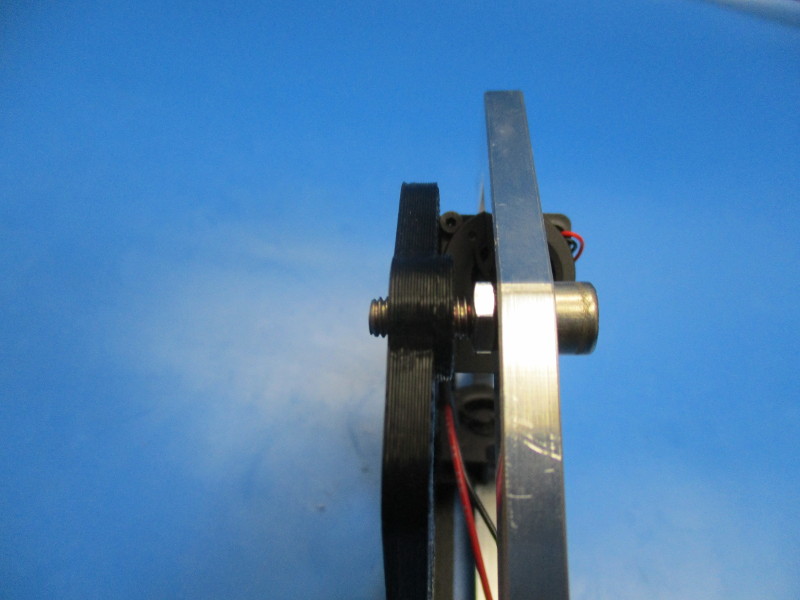
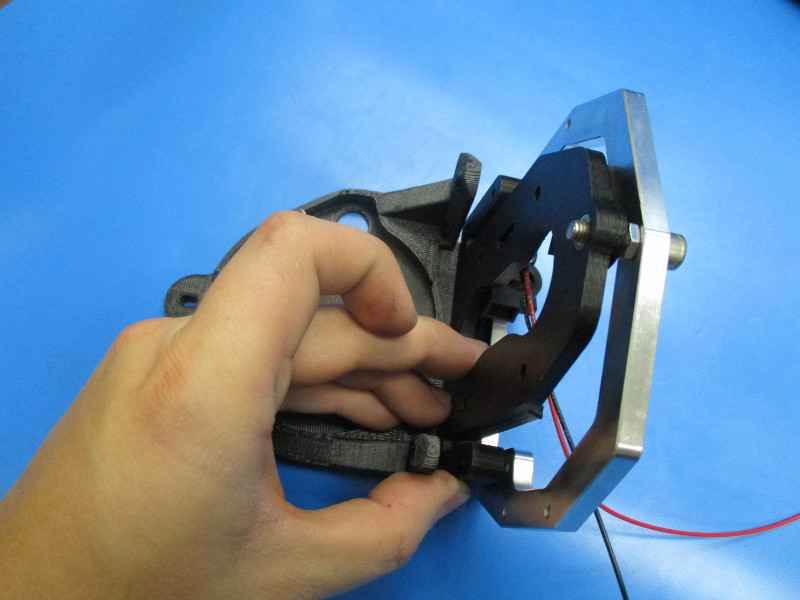
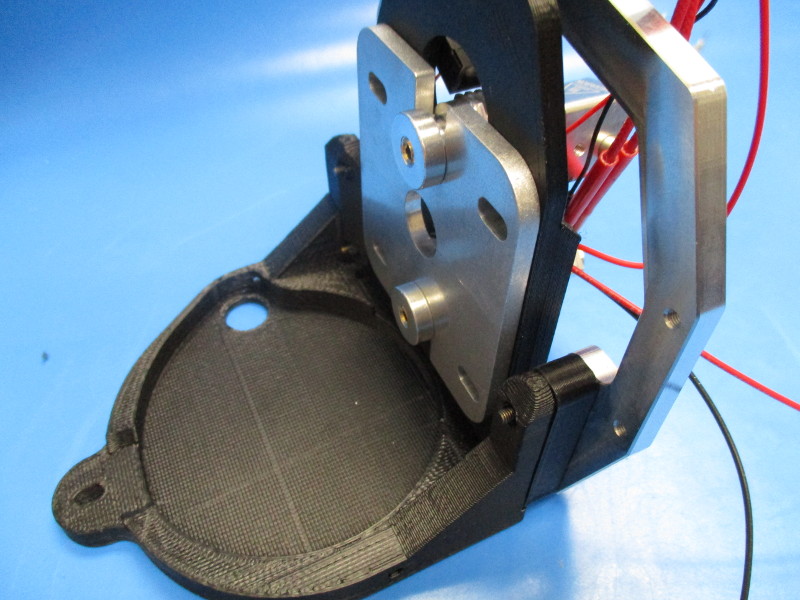
Align the back side of the flex plate with the mount.
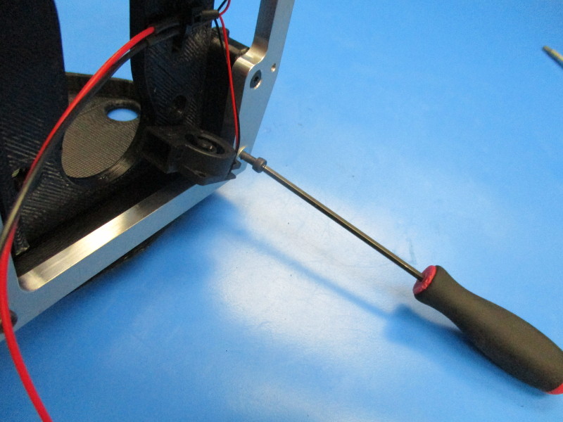
Insert the M3x25 FHCS screws into the counter sunk holes on the lower bracket. The screws should line up with the top threaded inserts. Torque to 3in*lbs.
Insert the M3x25 SHCS screws with washers into the bottom holes (see image “lower holes” for hole locations)
Torque down to 3in*lbs

Gather parts
1x Extruder body (PP-GP0186)
1x large herringbone (assembly)
1x extruder washer (PP-GP0060)
3x- M8 zinc plated washer (HD-WA0006)
2x- 608 bearing (HD-MS0282)
1x- M8 nyloc nut (HD-NT0002)
4x- M4 nut (HD-NT0011)
Tools required:
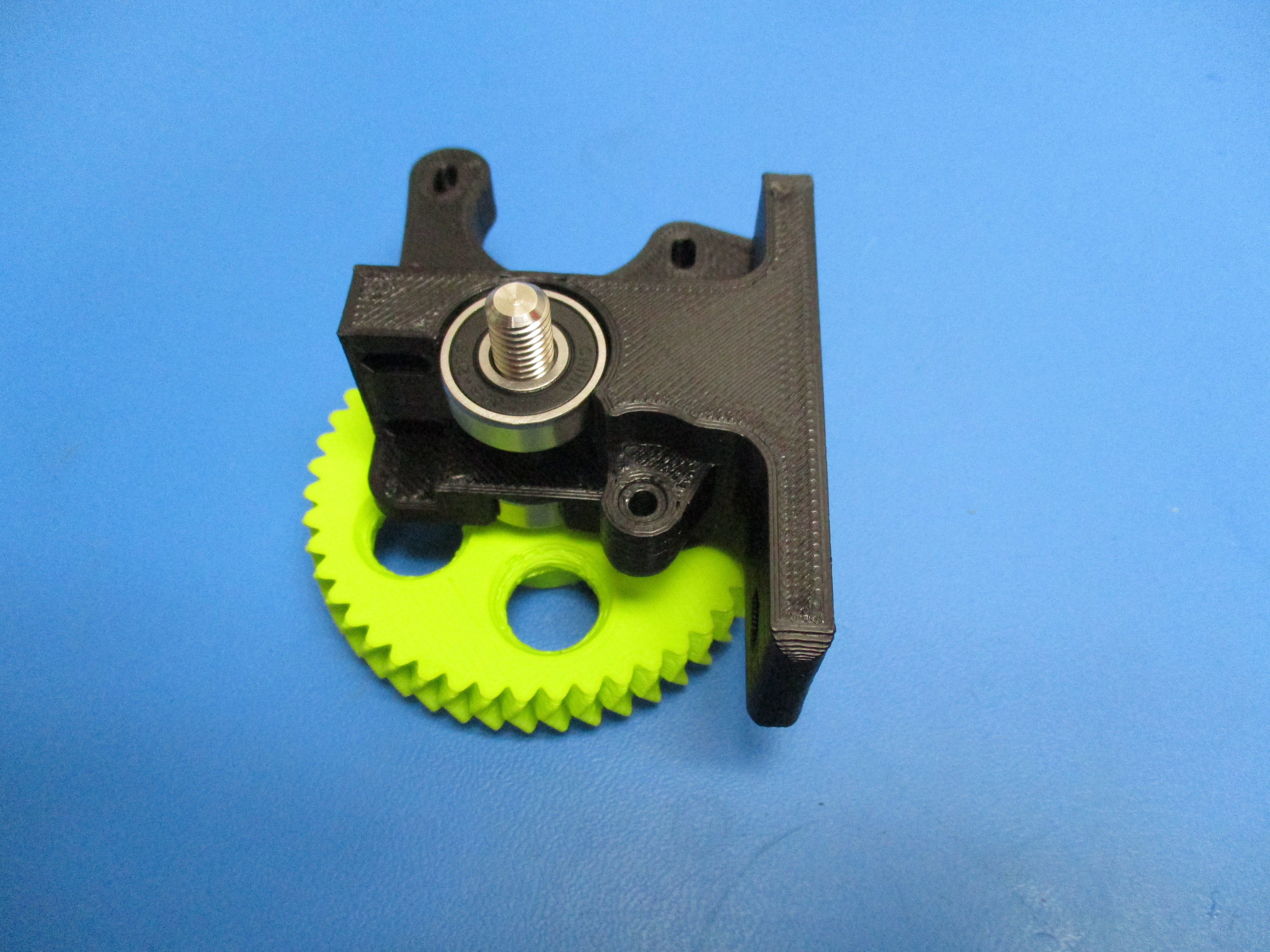
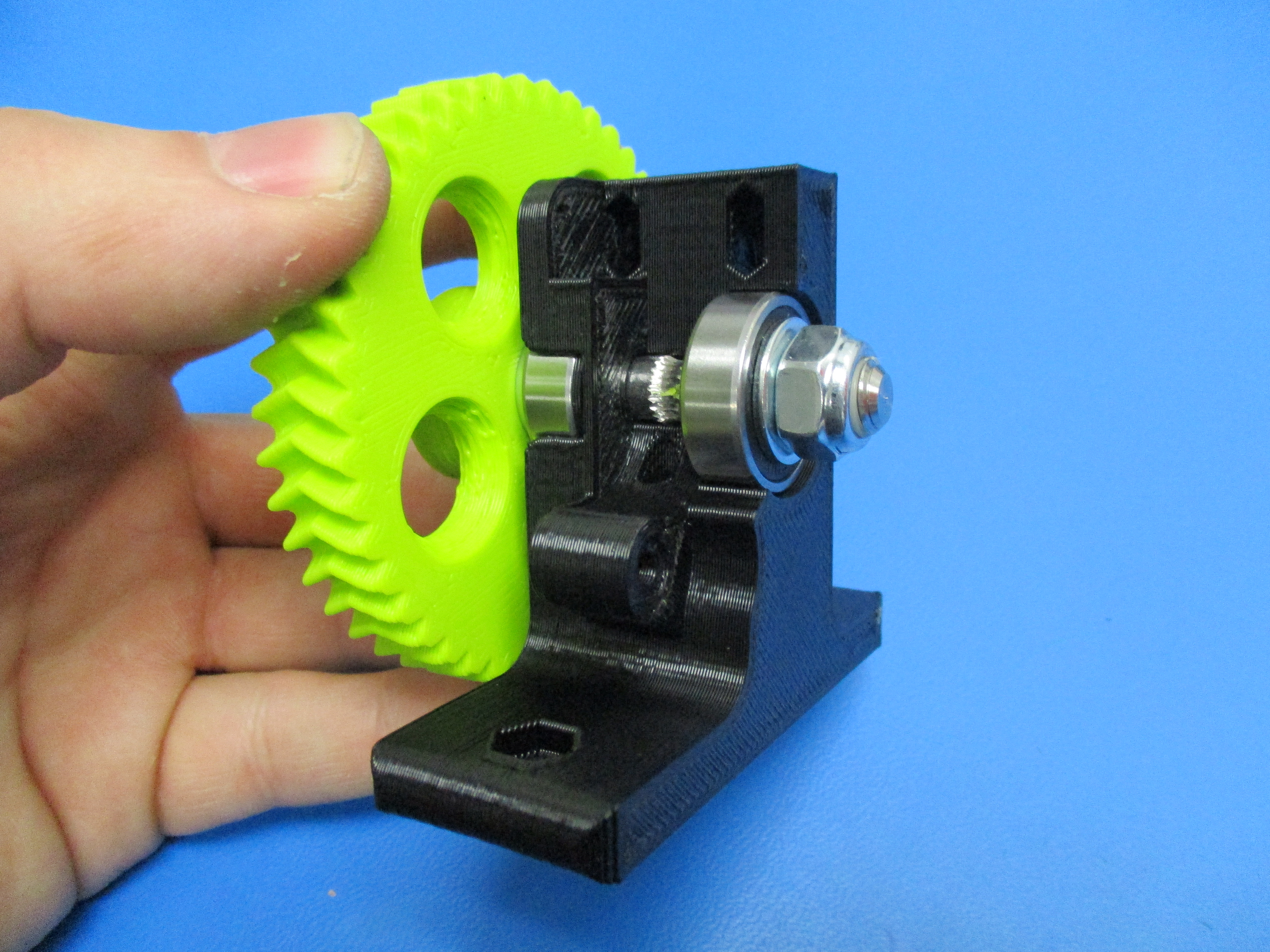
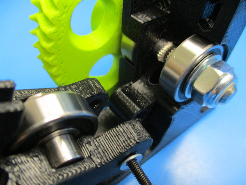
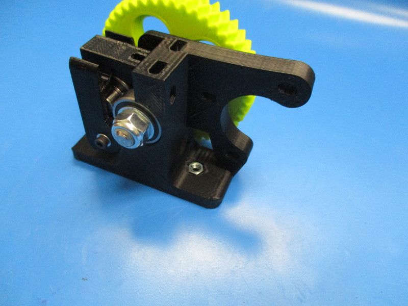
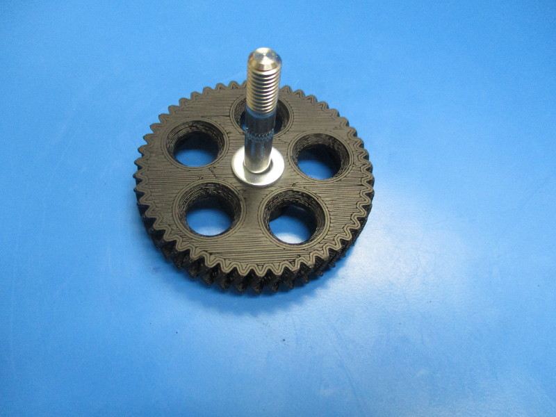
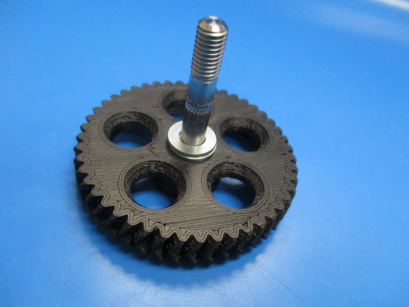
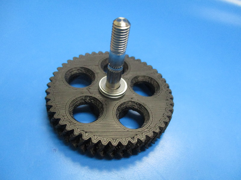
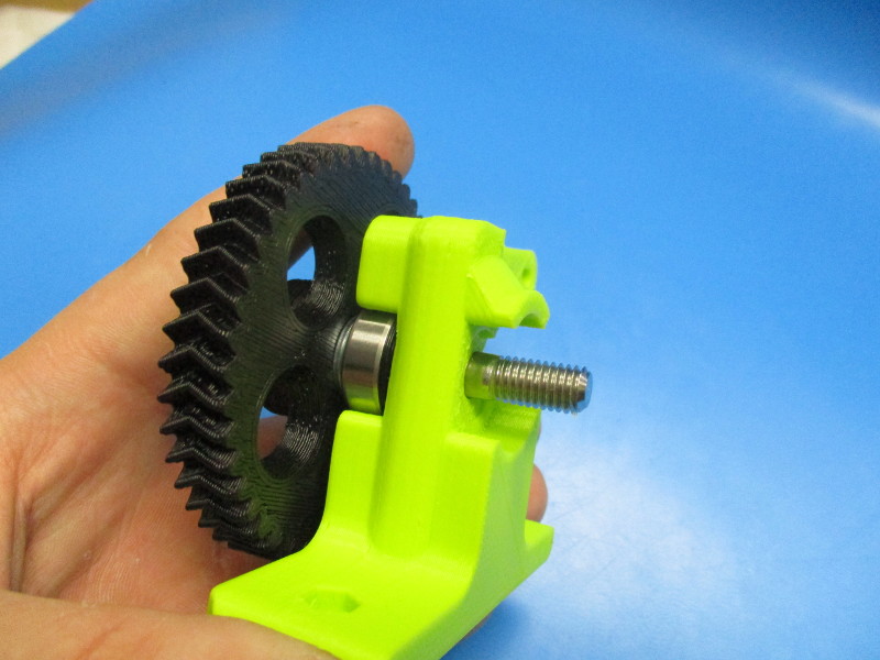
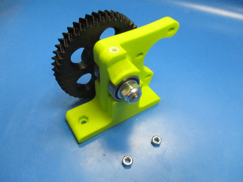
Place two M8 washer onto the hobbed bolt, that has been pressed into the large herringbone gear
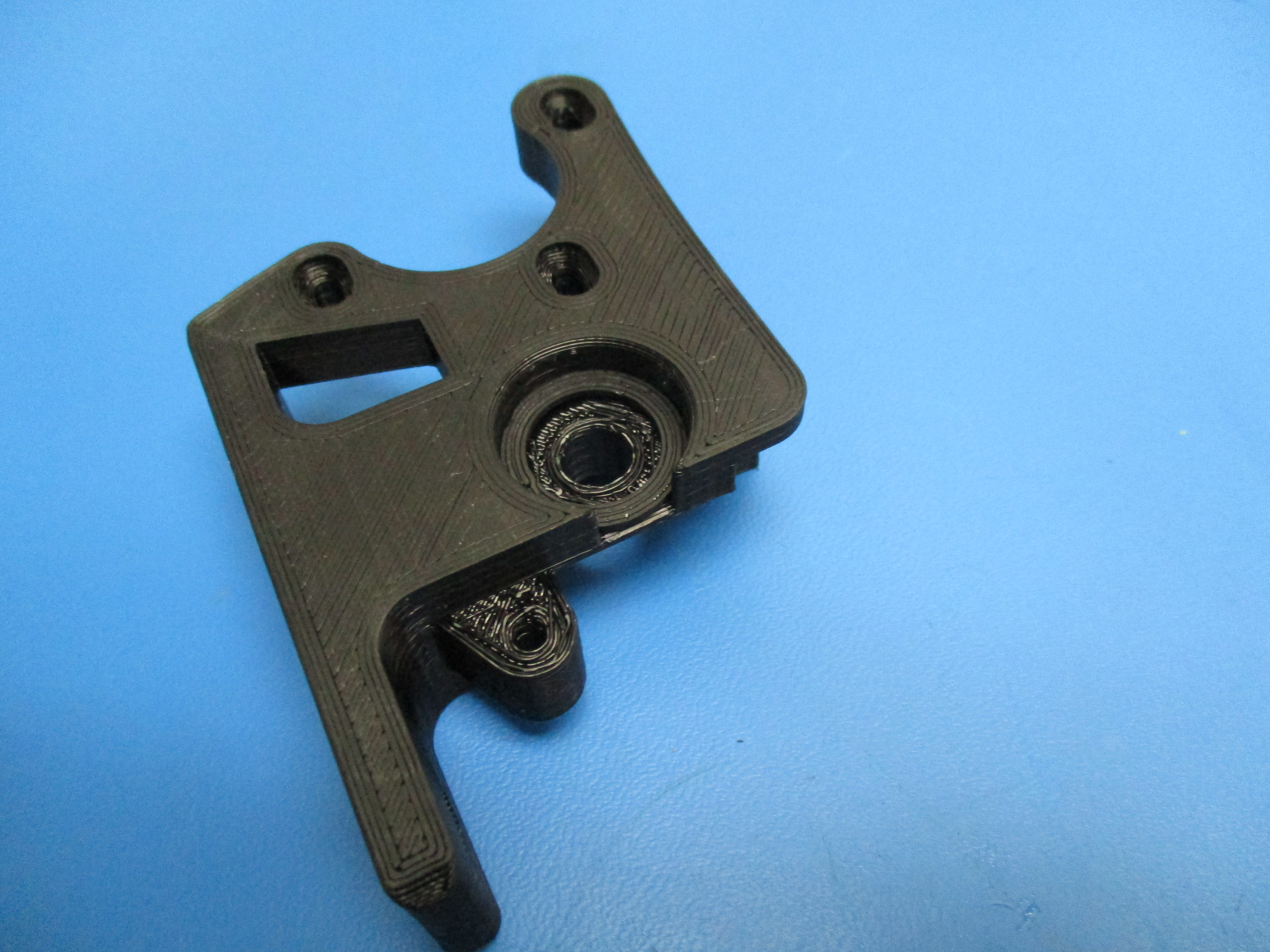
Lay the body on its side with the smooth surface facing up. Place the extruder washer into the bearing slot.
Place 608 bearing into the bearing slot.
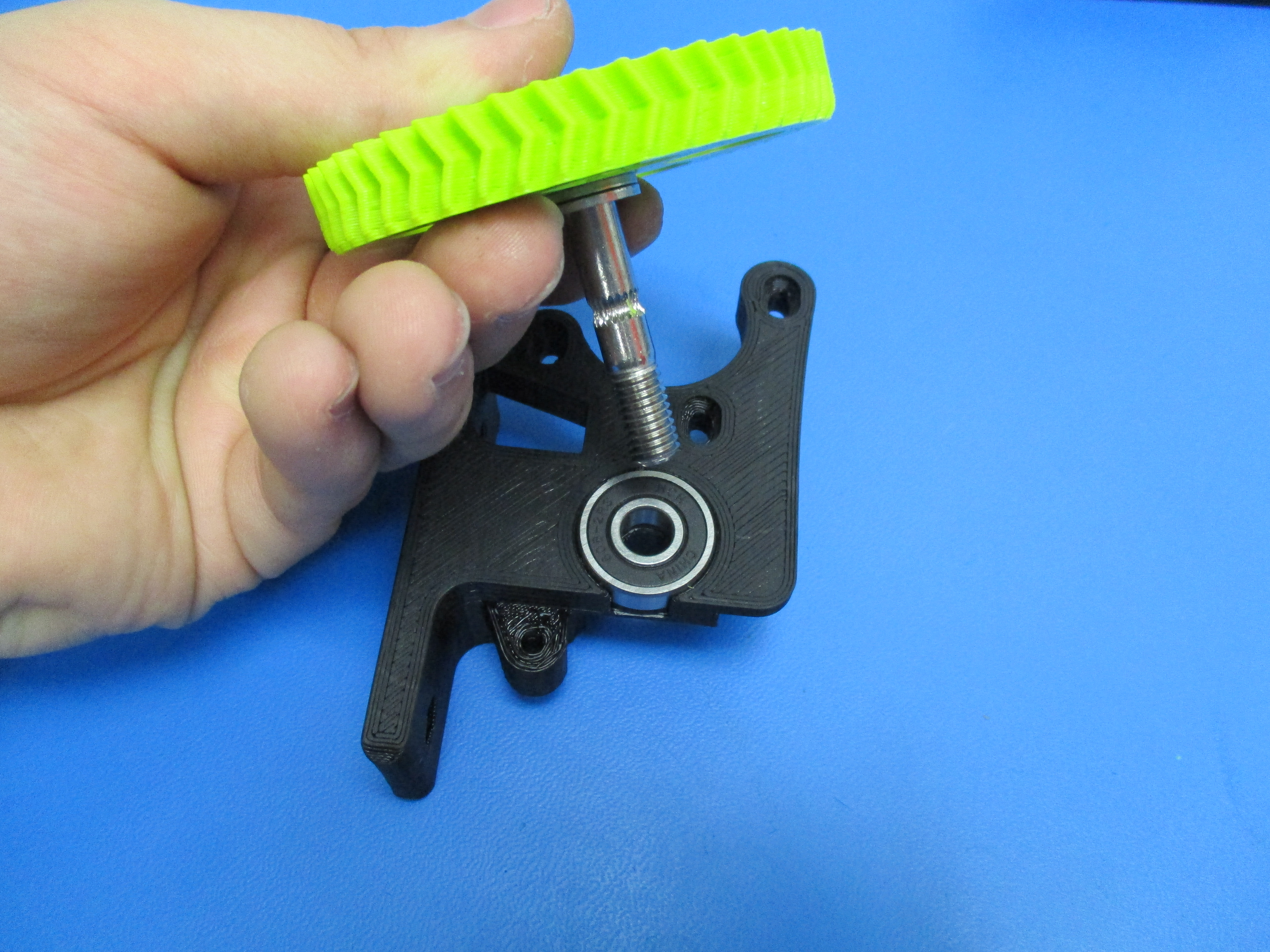
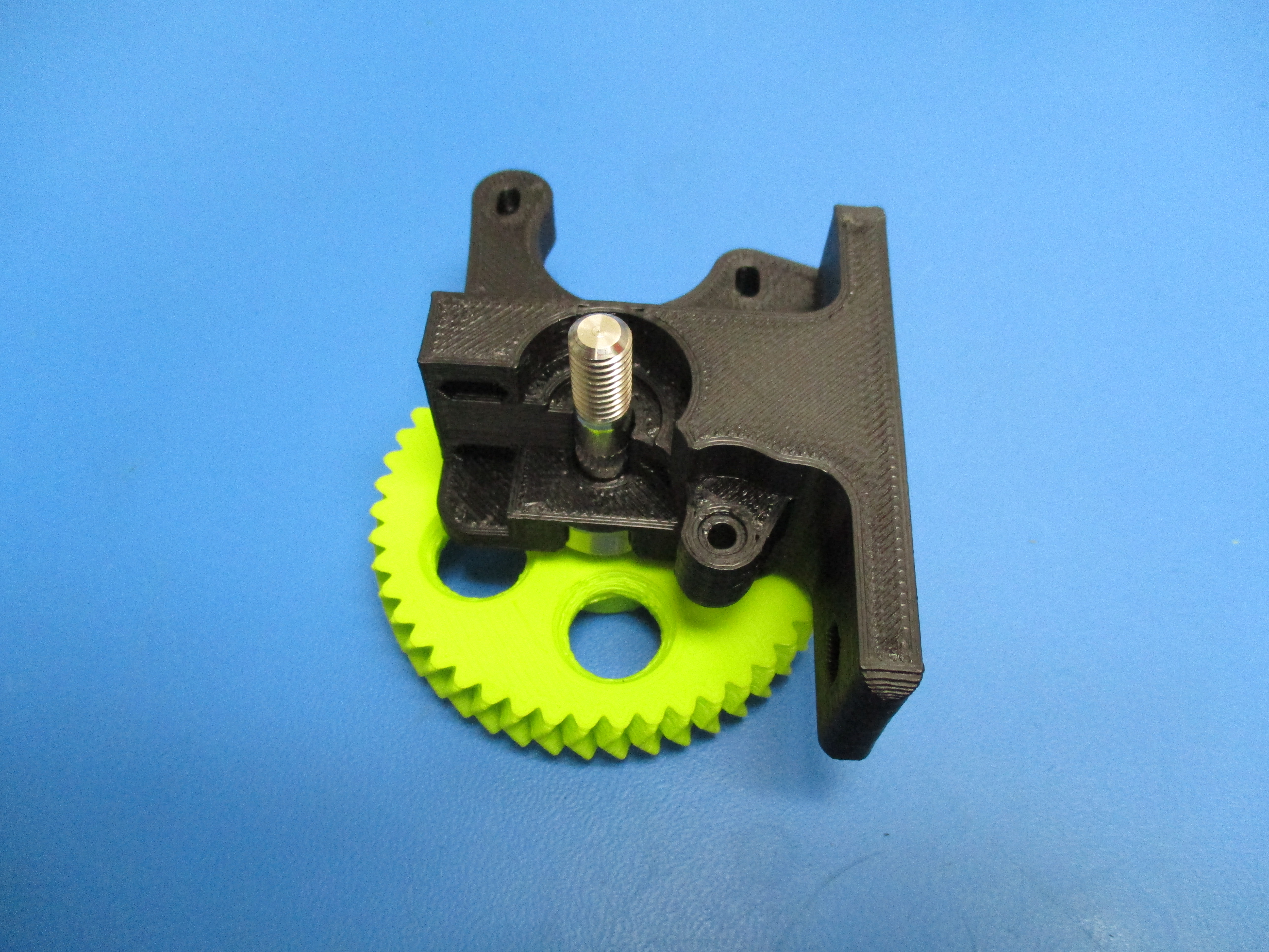
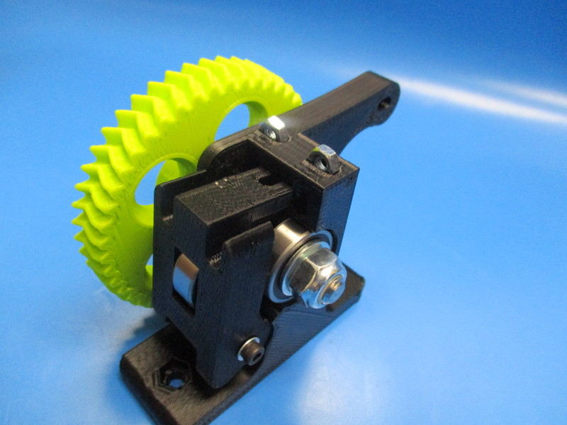
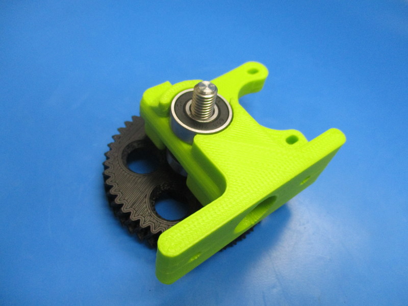
Install the large herringbone gear with washers by inserting the hobbed bolt portion into the 608 bearing and through the body.
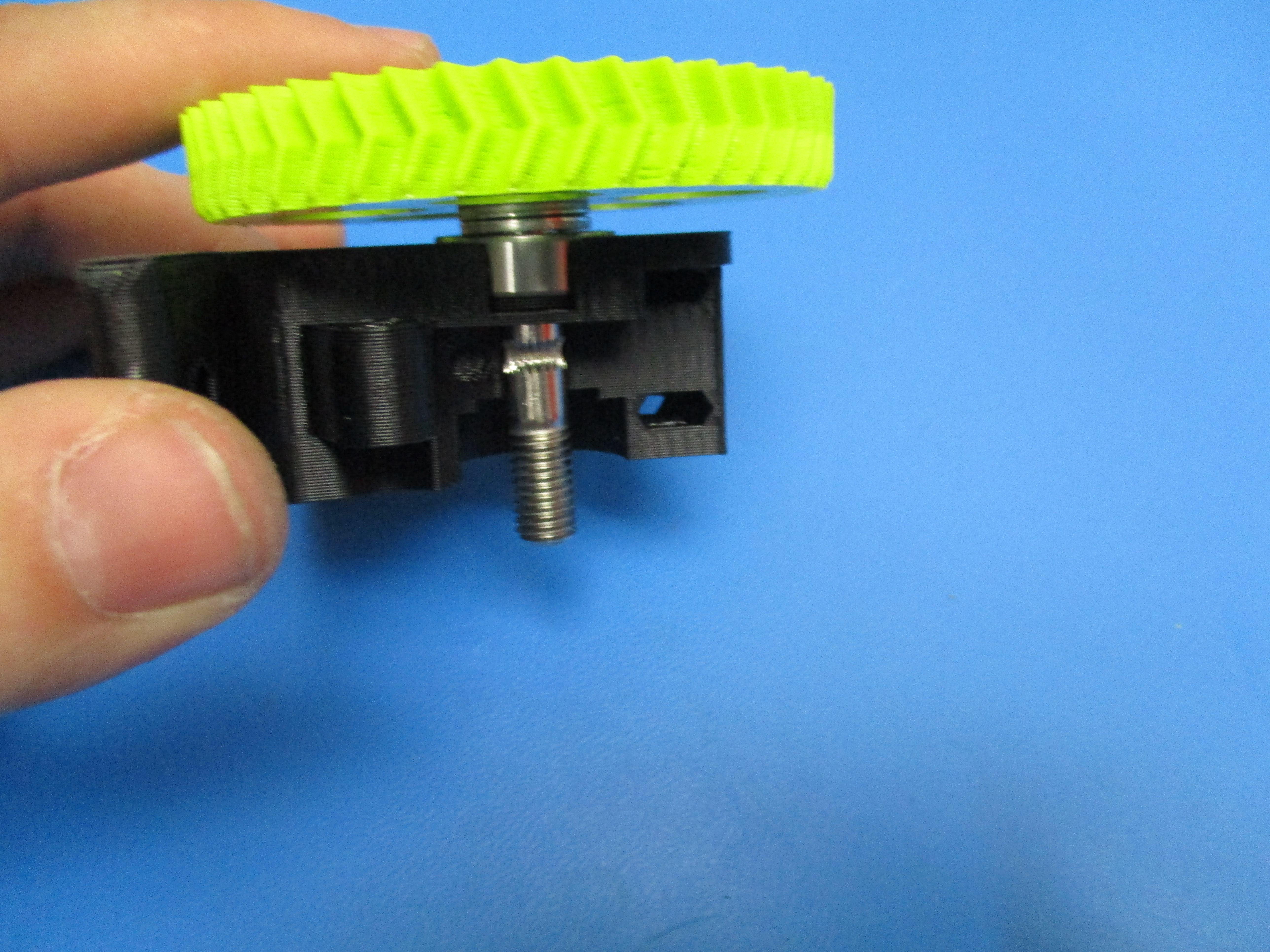
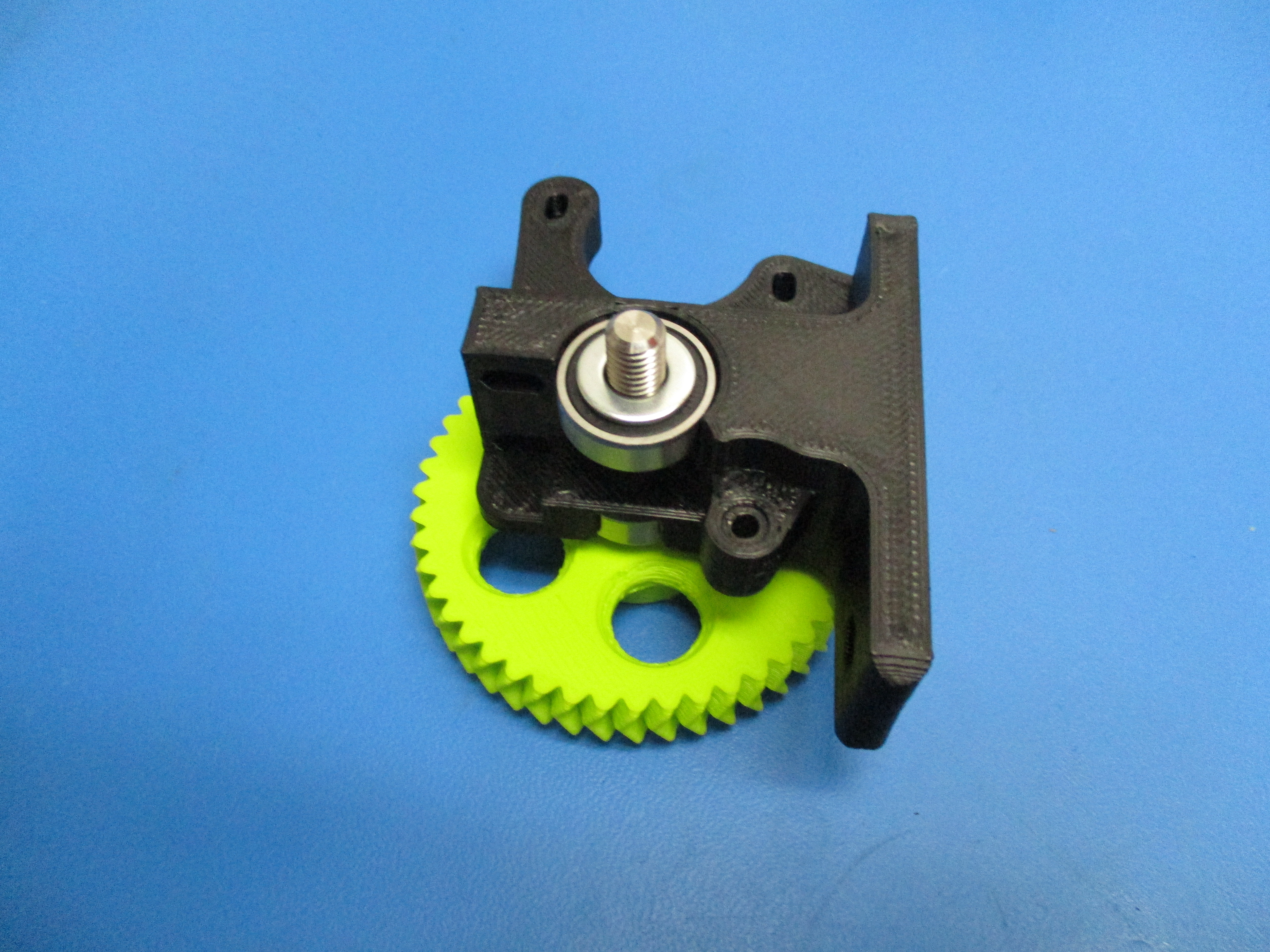
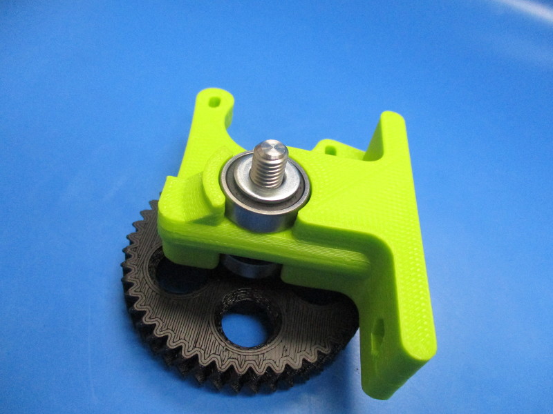
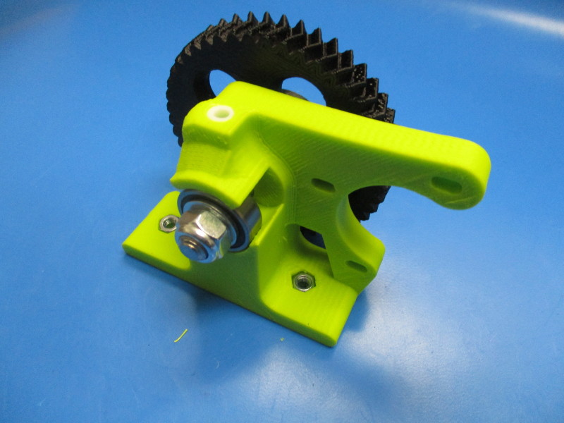
Rotate the body so that it rests on the large herringbone gear. Install the second 608 bearing onto the threaded portion of the hobbed bolt. Slide the bearing down so that it sits against the body.
Slide an M8 washer over the hobbed bolt so that it lays on top of the 608 bearing.
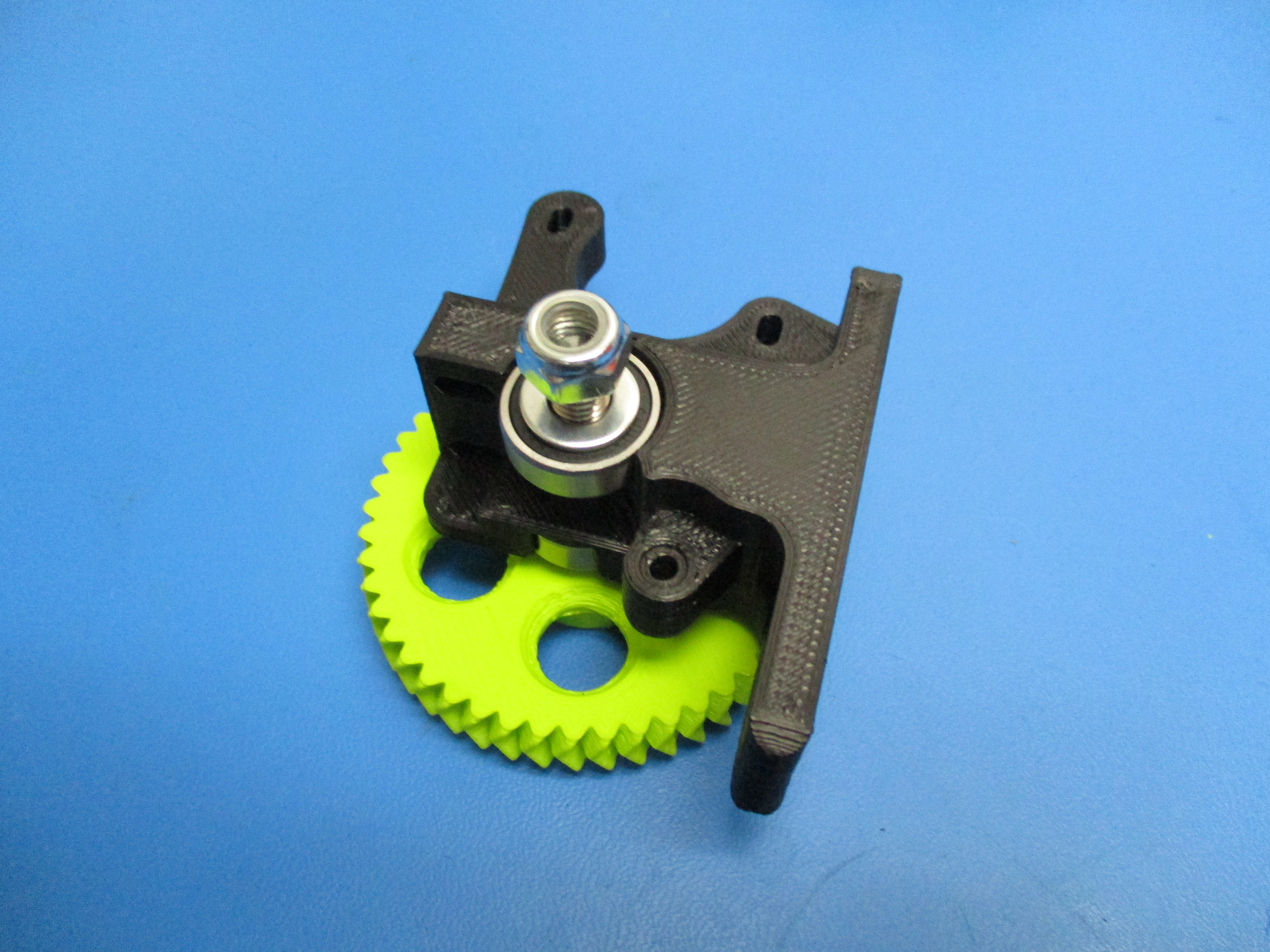
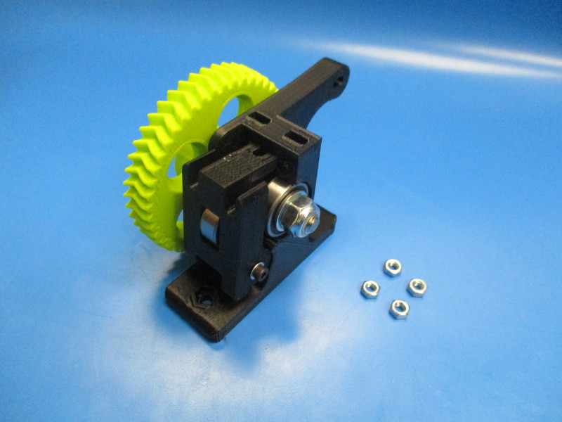
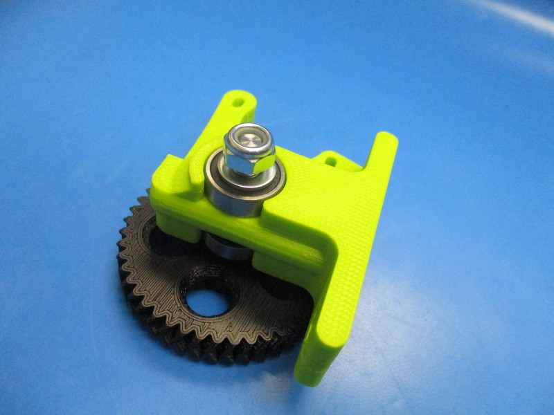
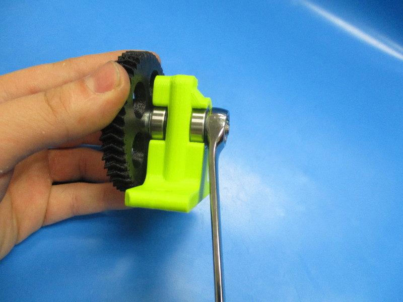
Fasten the M8 nyloc nut onto the threaded portion of the hobbed bolt.
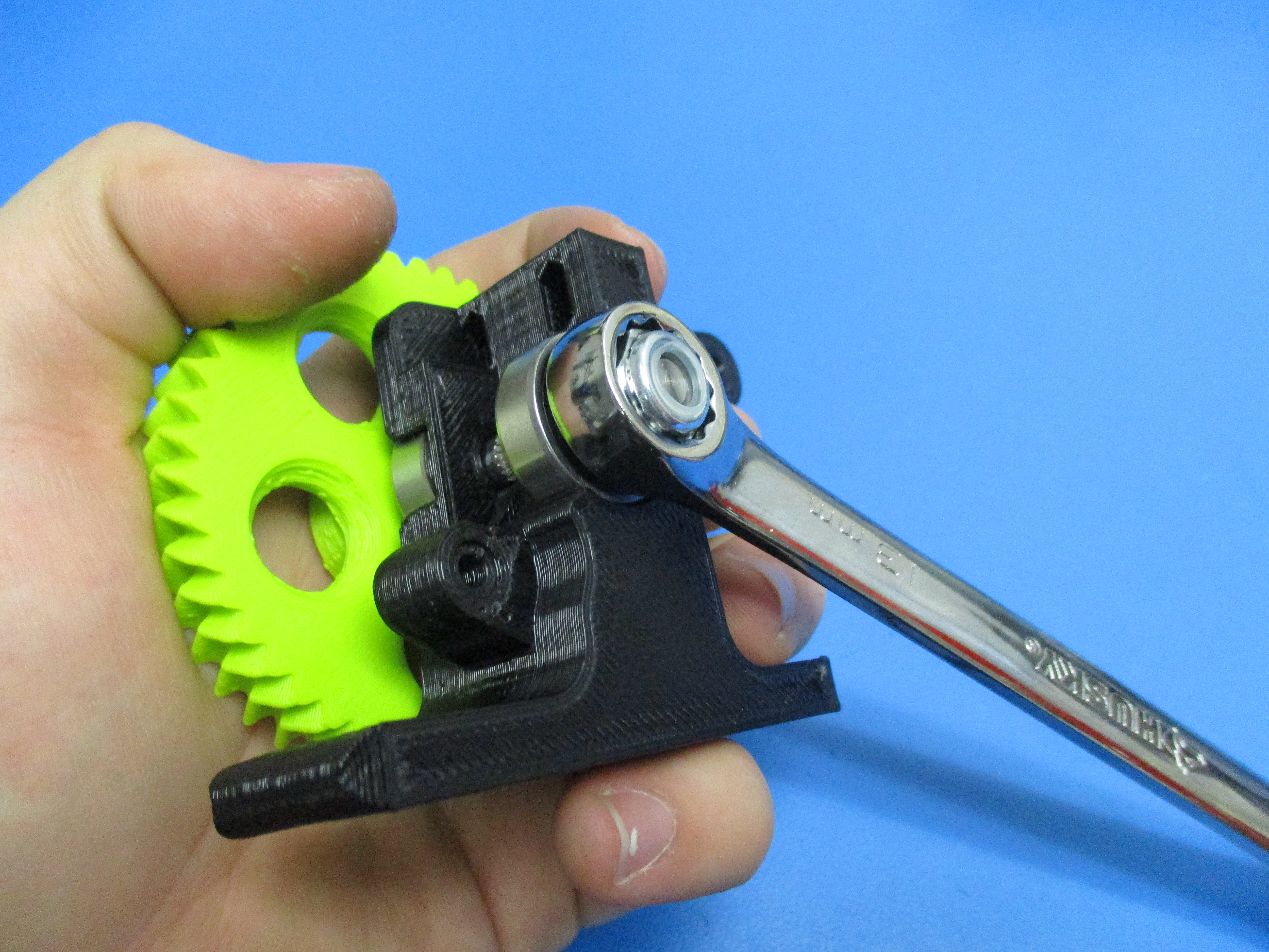
CAUTION: Over-tightening the M8 nyloc nut can cause the extruder body to fracture. Tighten the M8 nyloc nut down using a 13mm wrench
Tighten the M8 nyloc nut to where it is snug against the M8. (A good way to test to see if the nyloc nut is tight enough is to push the M8 washer under it with your thumb nail, if it moves then it needs to be tightened more)


Gather parts
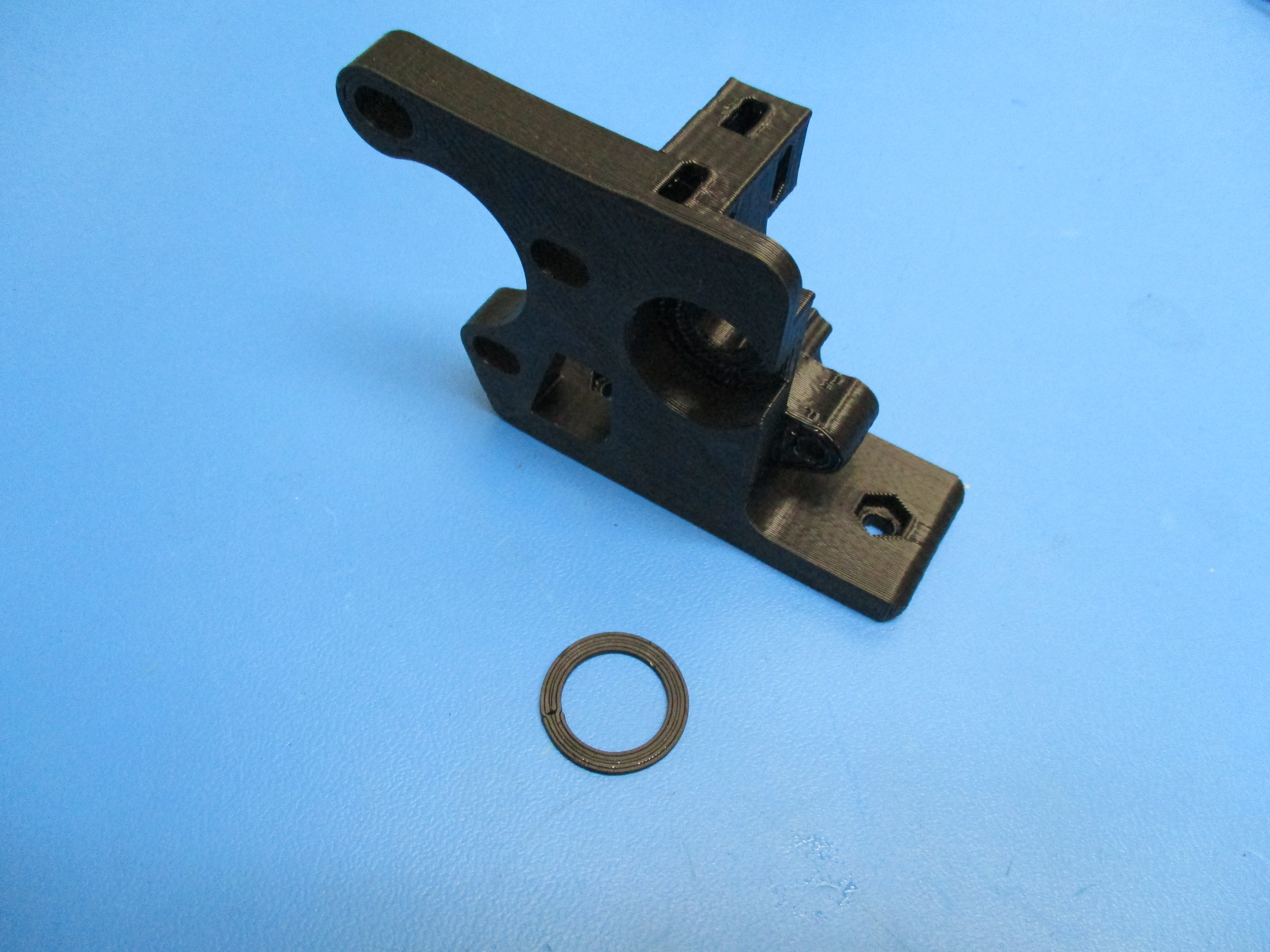
Idler block
M3x25 SHCS (HD-BT0041)
M3 washer (HD-WA0001)
M3 nut (HD-NT0004)
Tools needed:
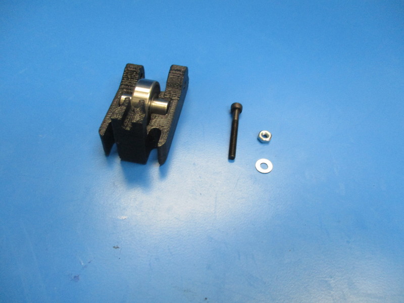
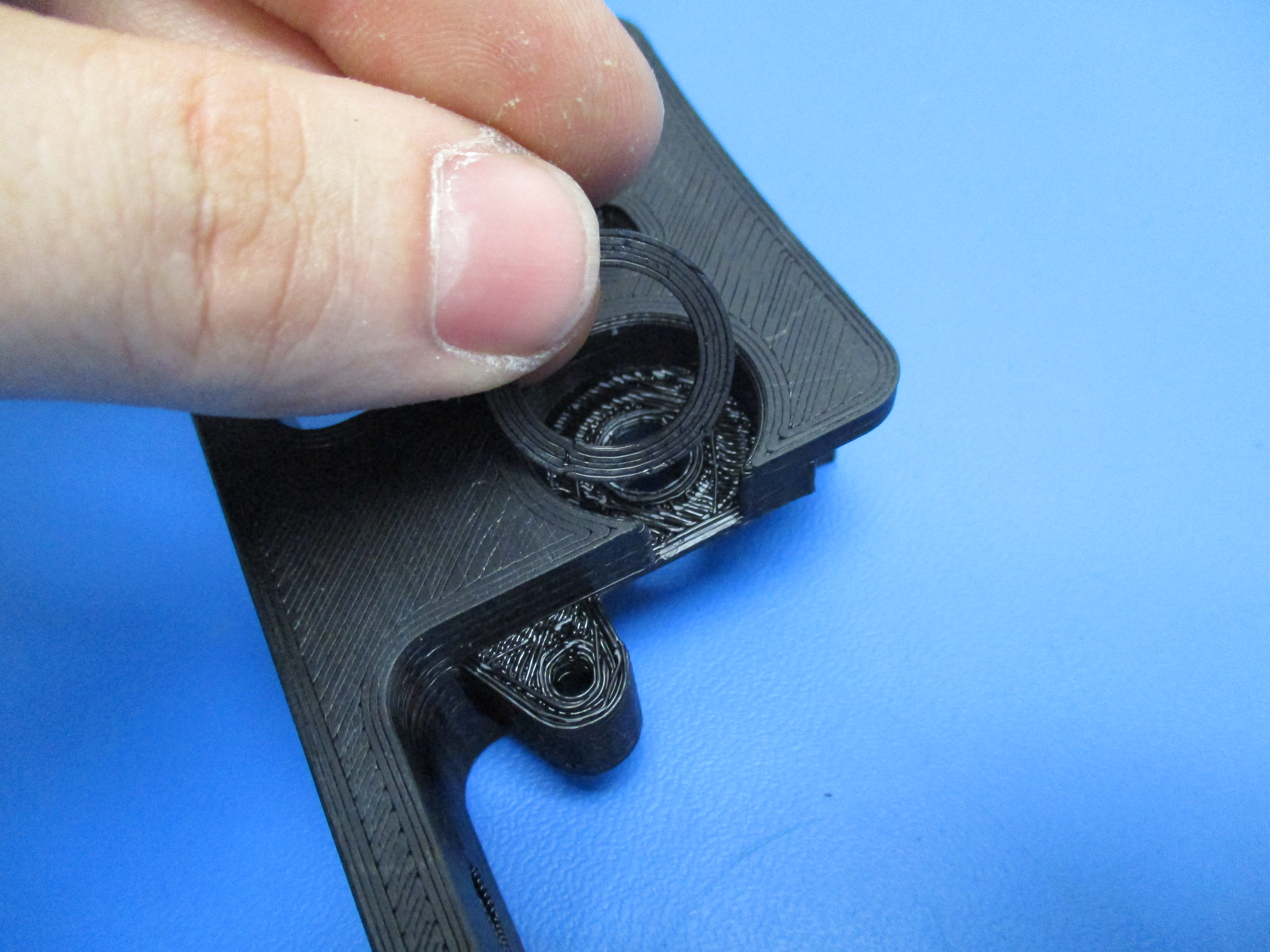
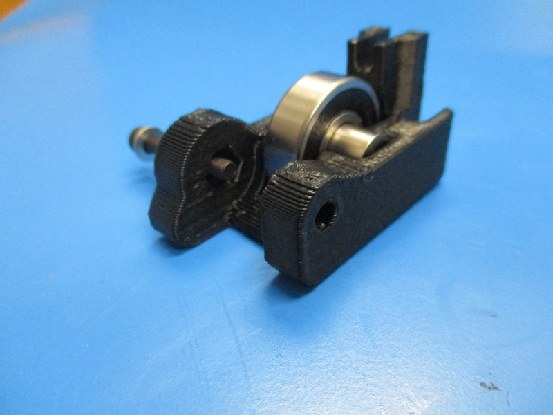
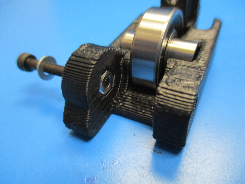
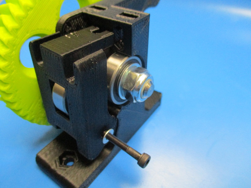
Insert the M3x25 SHCS with washer into the idler block. (see image “part orientation” for location of hole)
Insert the M3 nut into the hexagon cavity. Thread the M3 SHCS into the nut until the screw is flush with the nut.
Install the idler block onto the body. (see image “installing idler block”)
Tighten the M3x25 SHCS to secure the idler block onto the body. Torque to 5in*lbs

Gather parts
Instructions:
Insert the M4 nuts into the top slots in the body. (see image “top nuts” for slot location)
Press the nuts so that they sit in the slots.
Insert the other two M4 nuts into the hexagon shaped cavities at the base of the body.
Gather parts
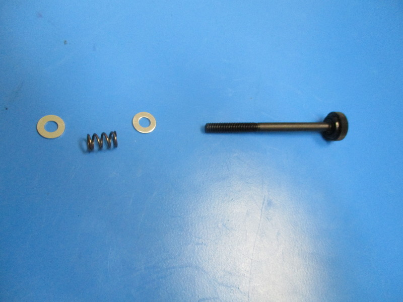
2x- M3x55 thumb screw
2x- extruder spring (HD-MS0027)
4x- M4 washer (HD-WA0005)
1x- extruder latch (PP-GP0091)
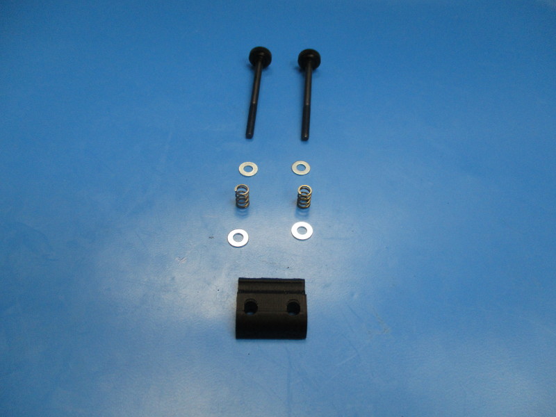
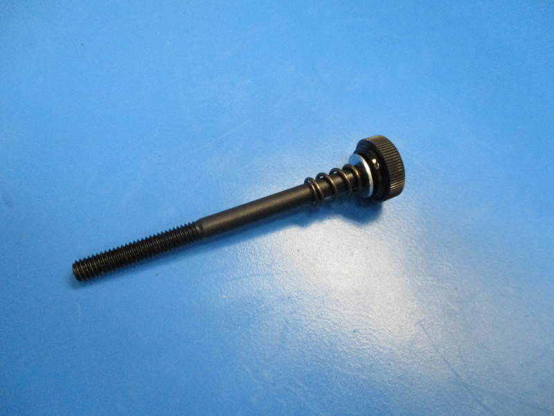
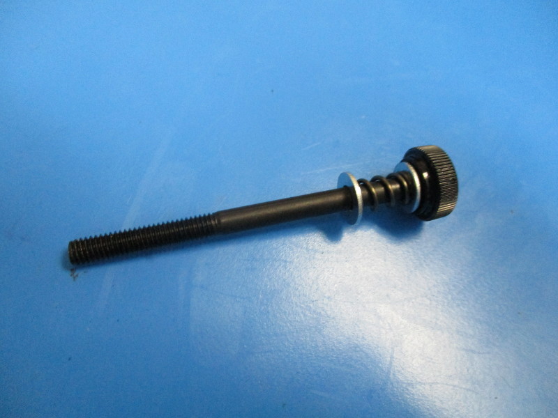
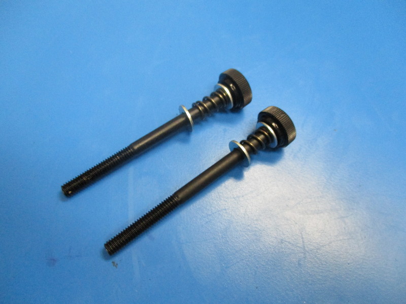
Install the hardware onto the M3x55 thumb screw in the order, washer, spring, washer.
Repeat to the second M3x55 thumb screw.
Install the thumb screws with hardware into the extruder latch. (see image “Extruder latch” for orientation of thumb screws in latch)


Line the extruder latch up with the slots in the idler block when it is sitting upright in the closed position.
Thread the thumb screws into the holes with the M4 nuts that were previously installed
The thumb screws don't need to be tightened all the way, leave them loose for now.


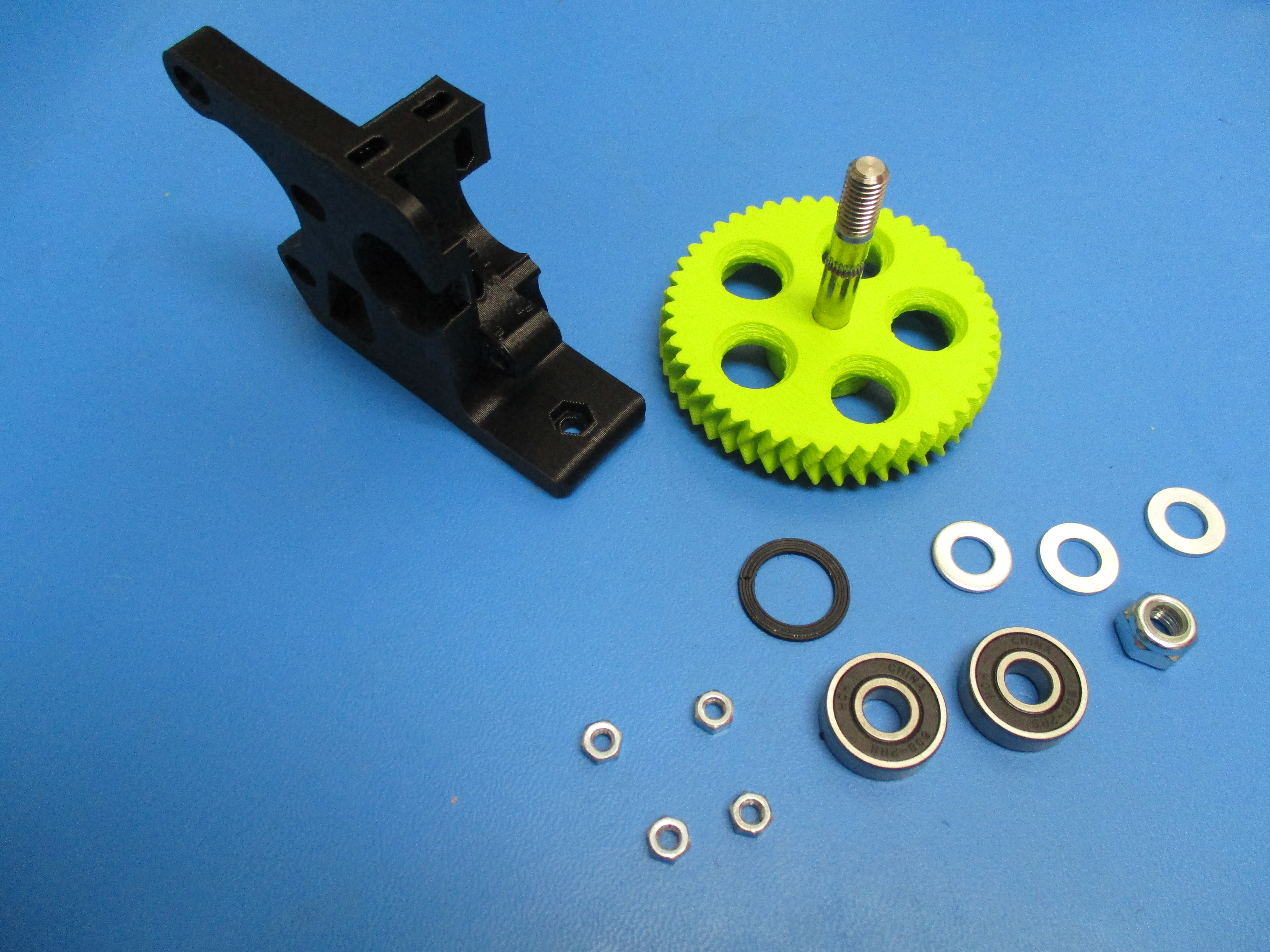
Gather parts
1x- Large herringbone gear
1x- flexystuder body
2x- 608 bearing (HD-MS0282)
3x- M8 washer (HD-WA0006)
1x- .5 mm M8 shim (HD-WA0008)
1x- M8 Nyloc Nut (HD-NT0002)
1x- Extruder washer (PP-GP0060)
Tools needed:

Start with the large herringbone gear
Place two M8 washer onto the hobbed bolt, that has been pressed into the large herringbone gear
Place one shim onto the hobbed bolt
-Placing the extruder washer into the body
Lay the body on its side with the smooth surface facing up. Place the extruder washer into the bearing slot.
Place 608 bearing into the bearing slot.
Install the large herringbone gear with washers by inserting the hobbed bolt portion into the 608 bearing and through the body.
Rotate the body so that it rests on the large herringbone gear. Install the second 608 bearing onto the threaded portion of the hobbed bolt. Slide the bearing down so that it sits against the body.
Slide an M8 washer over the hobbed bolt so that it lays on top of the 608 bearing.
Thread the M8 nyloc nut onto the threaded portion of the hobbed bolt.
Tighten the M8 nyloc nut using the 13mm driver. Tighten until the washer doesn't move freely
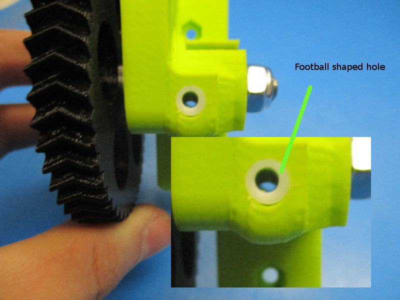
Check to see if the filament hole and hobbed bolt are aligned correctly. Looking through the top of the extruder down the hole drilled into the PTFE tubing, there should be a football shaped gap between the inner wall of the PTFE tubing and the hobbed bolt.
Gather parts
Instructions:
Install two M4 nuts into the base of the extruder

Gather parts
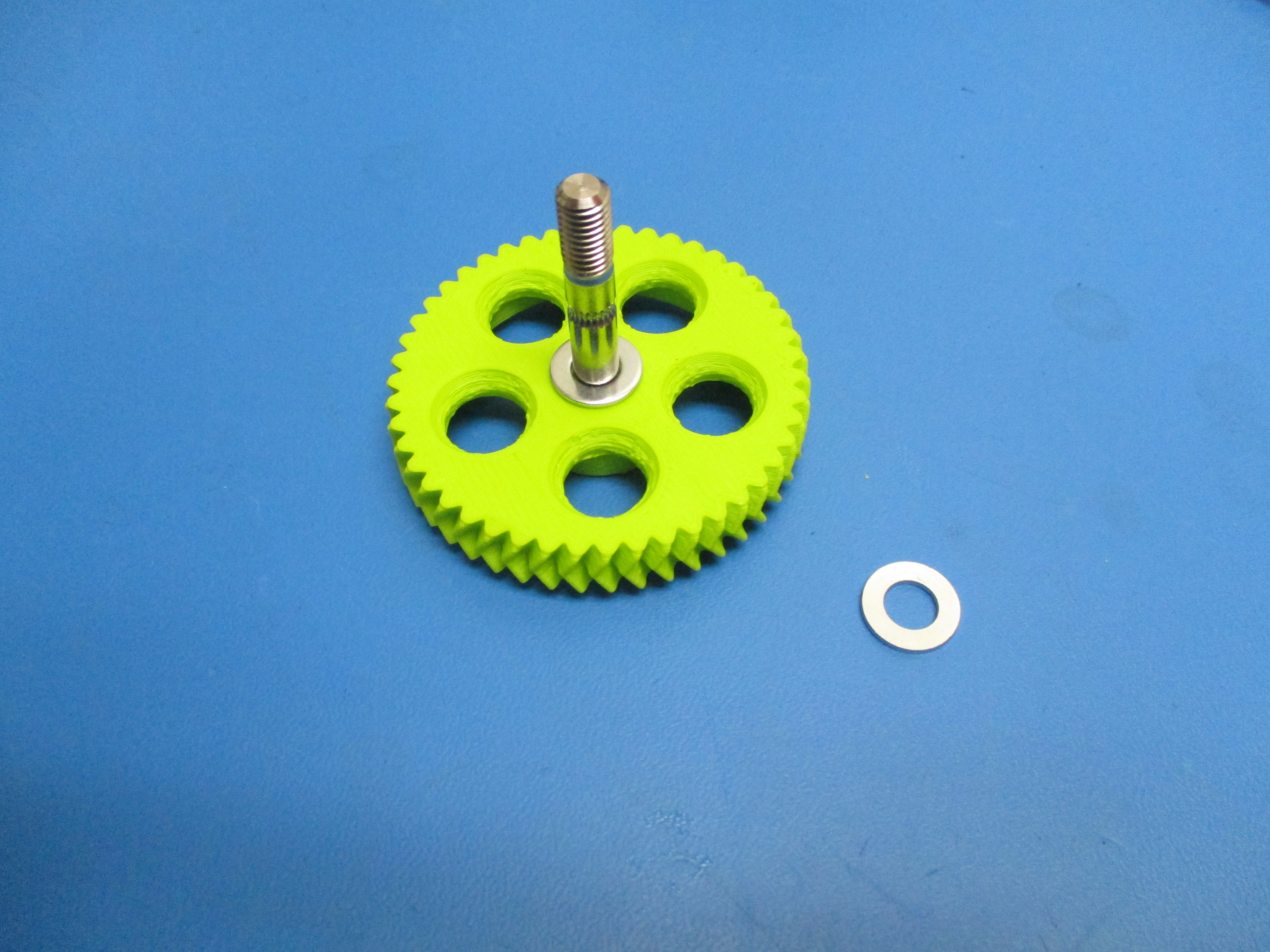
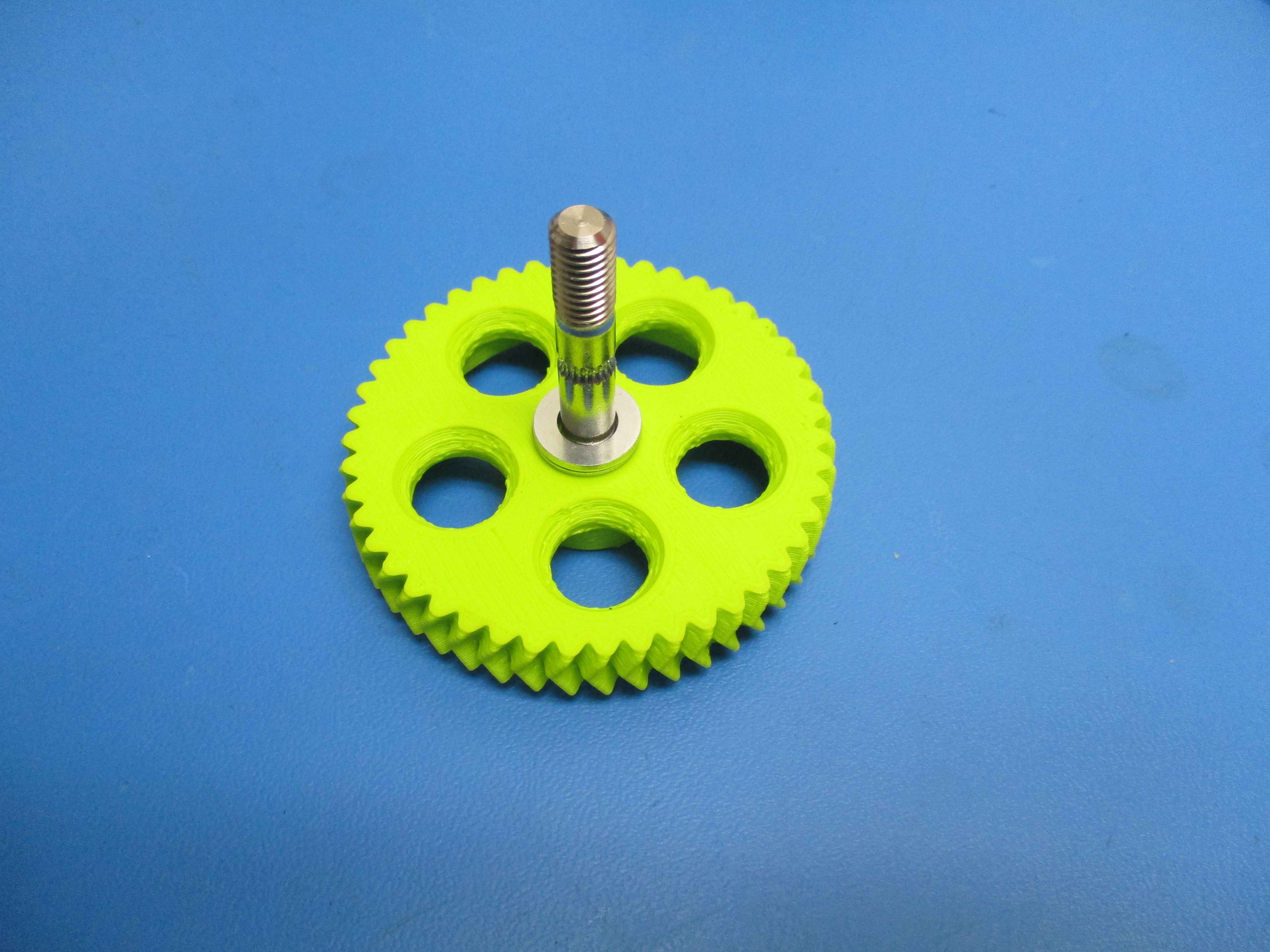
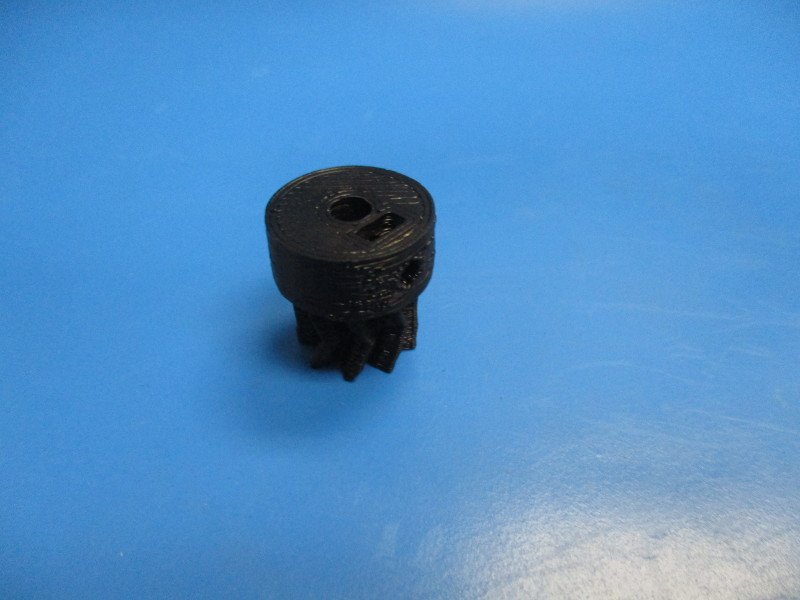
Small herringbone gear, green (PP-GP0192)
M3 set screw (HD-BT0012)
M3 nut (HD-NT0004)
Tools needed:
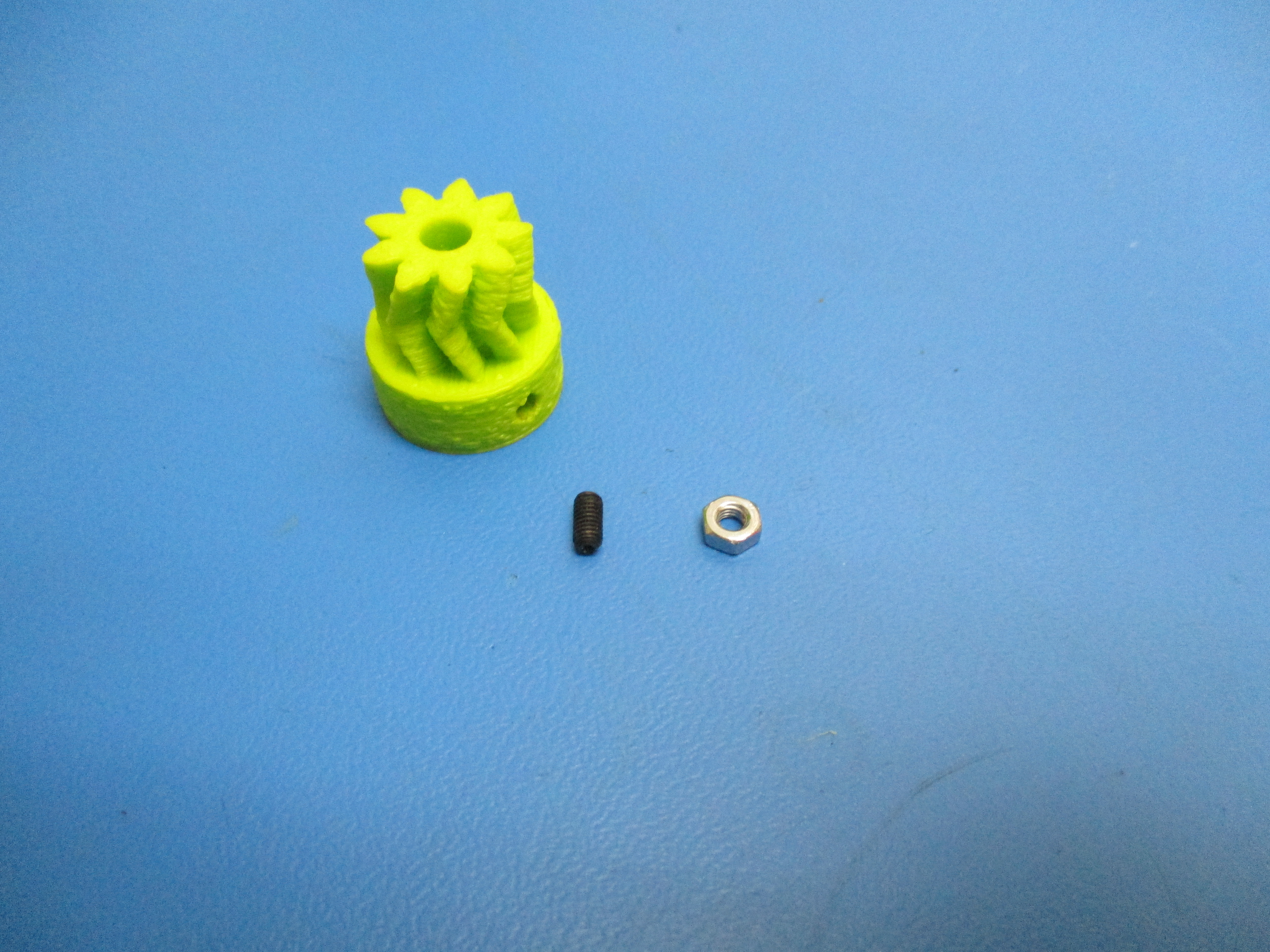
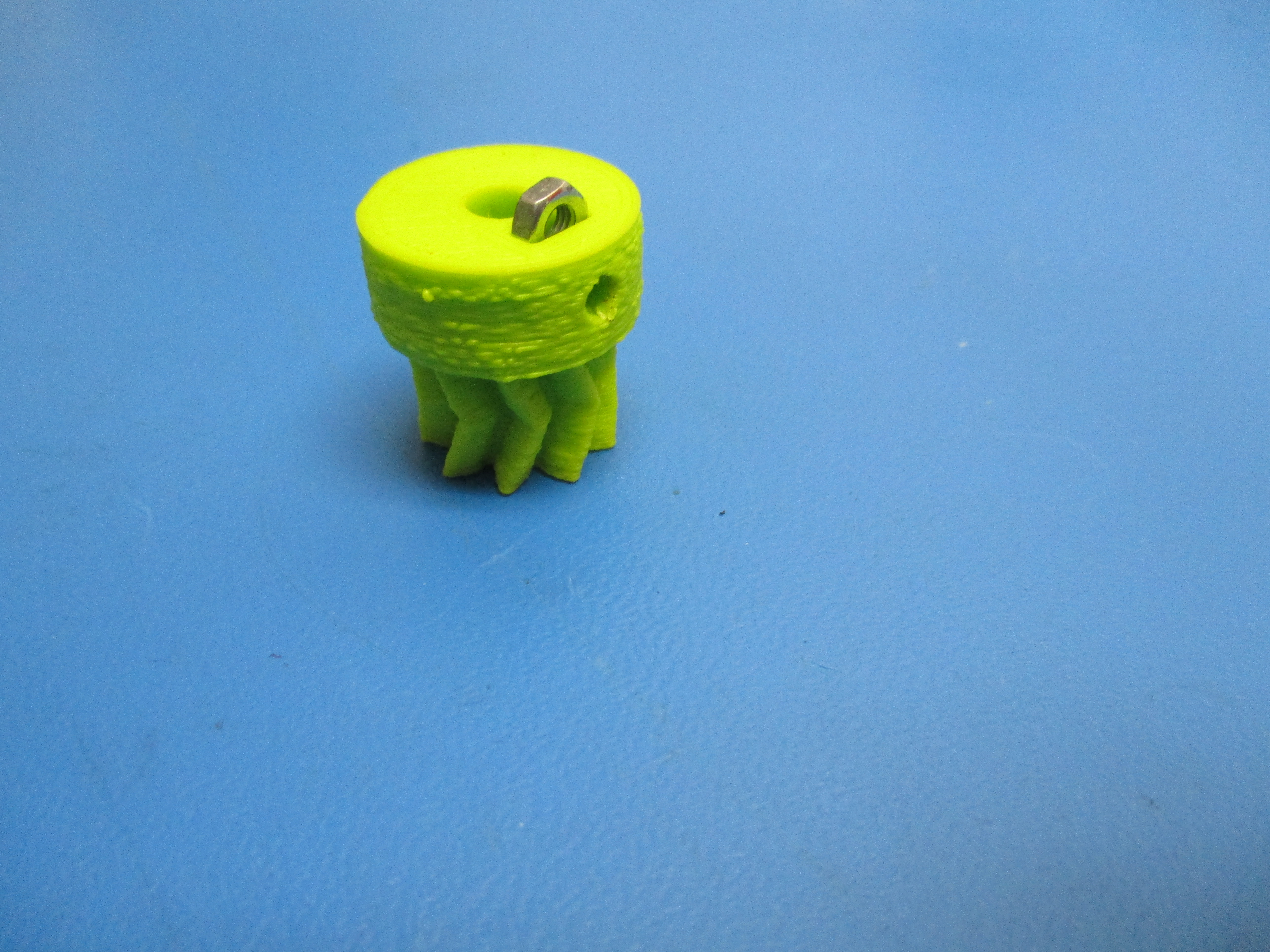
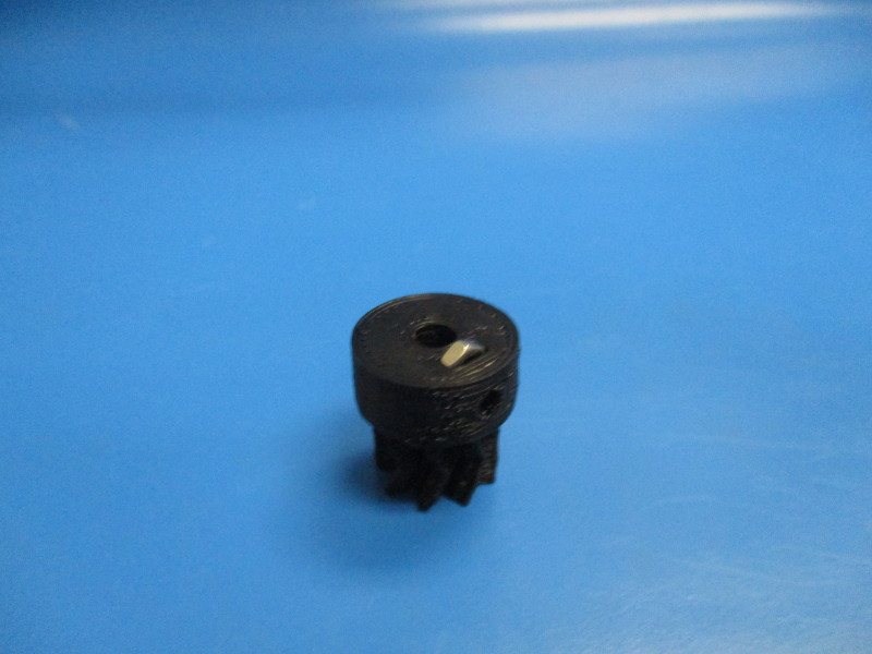
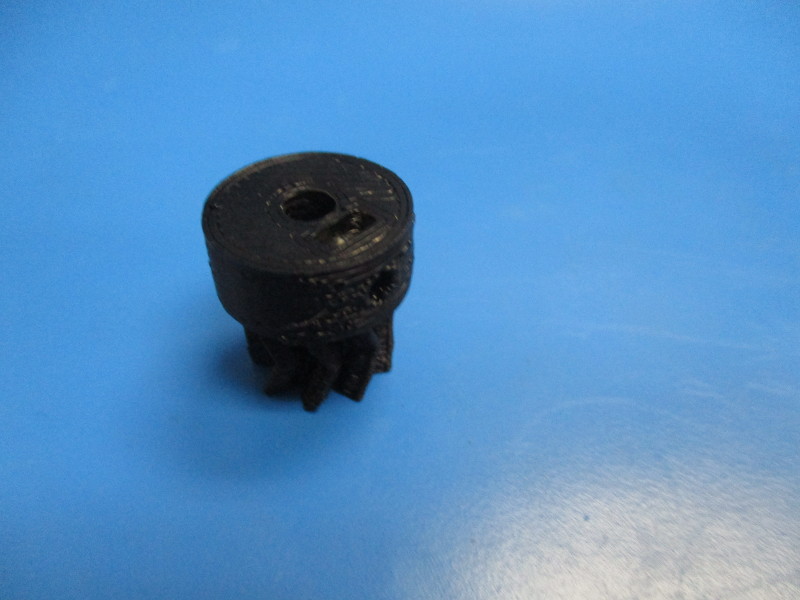
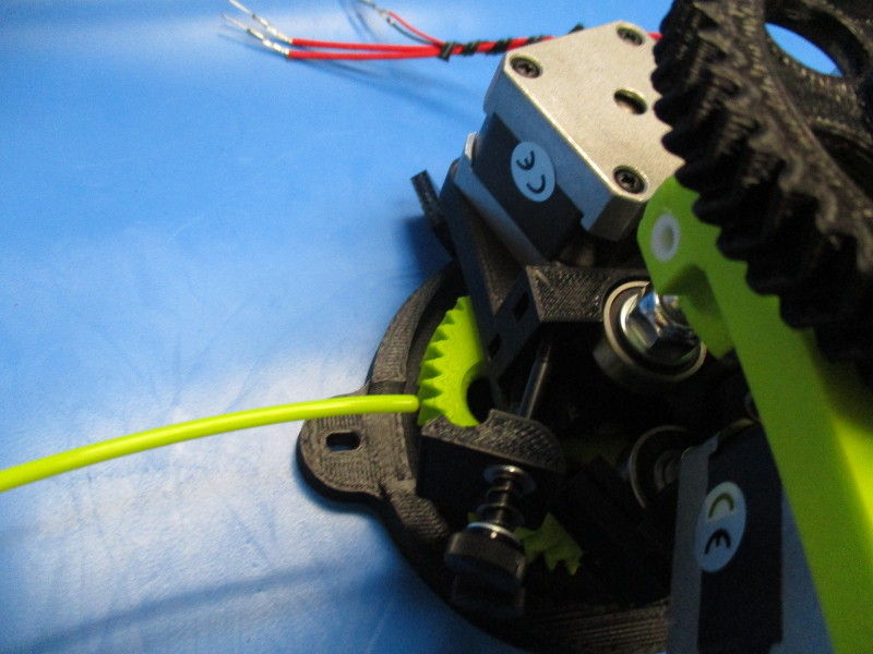
Lay the small herringbone gear on the gear face so the nut slot is facing up (see image for gear orientation)
Press nut into slot until holes in the small gear and the nut line up.
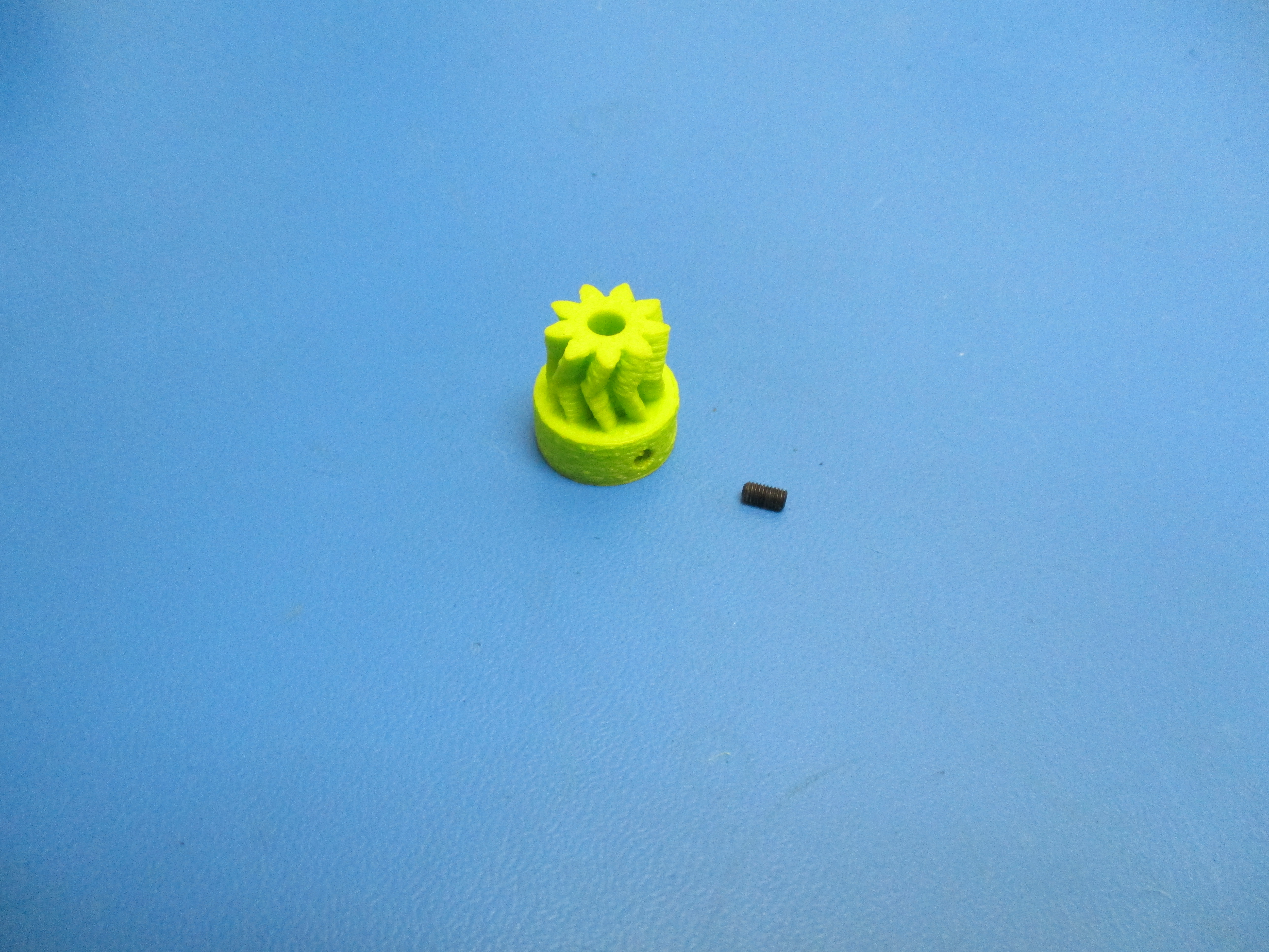
Rotate the gear so that the slot is facing down
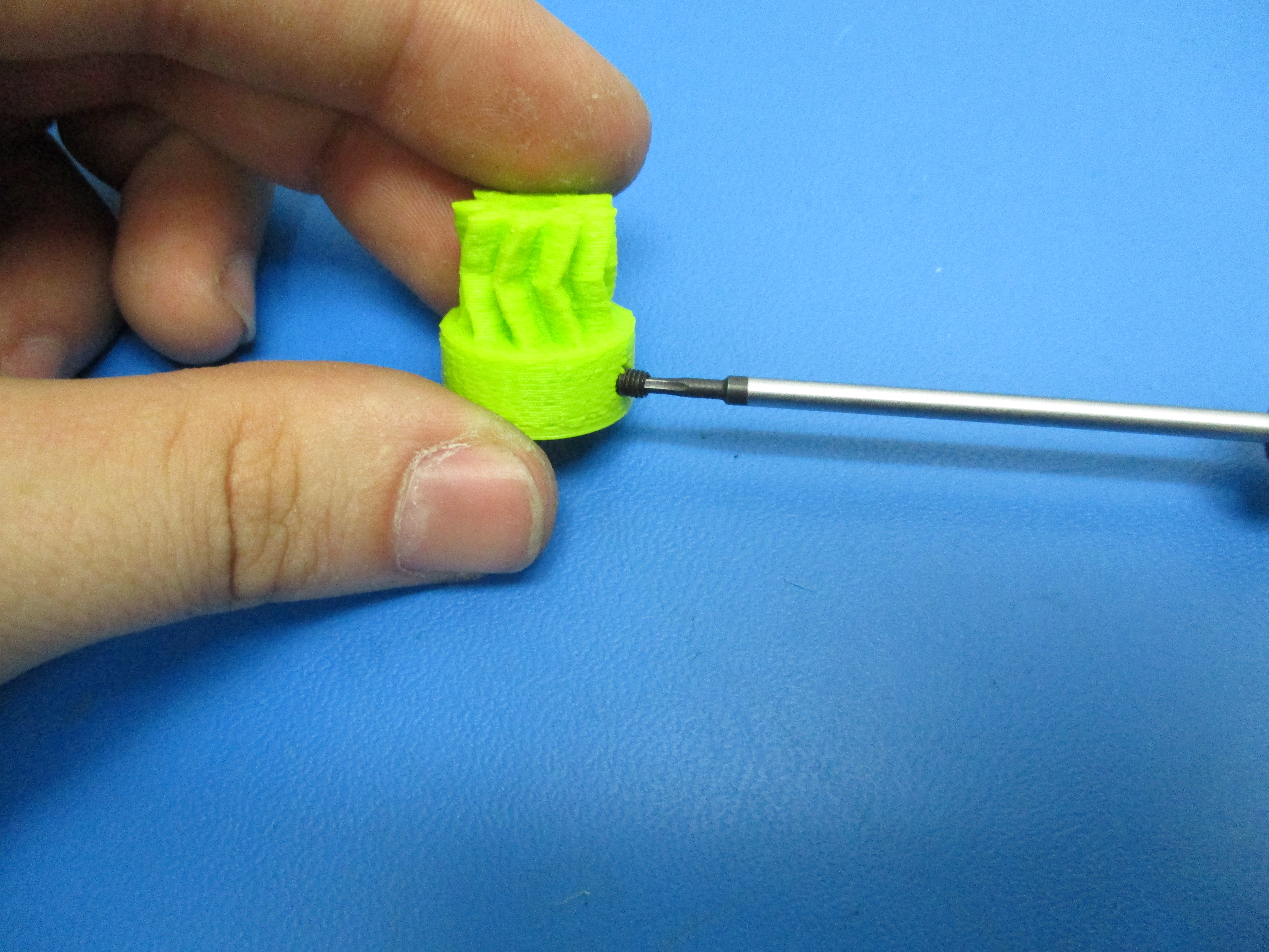
Install the set screw into the hole that is aligned with the nut using a 1.5mm driver
Thread until the head of the set screw is flush with the plastic


Gather parts
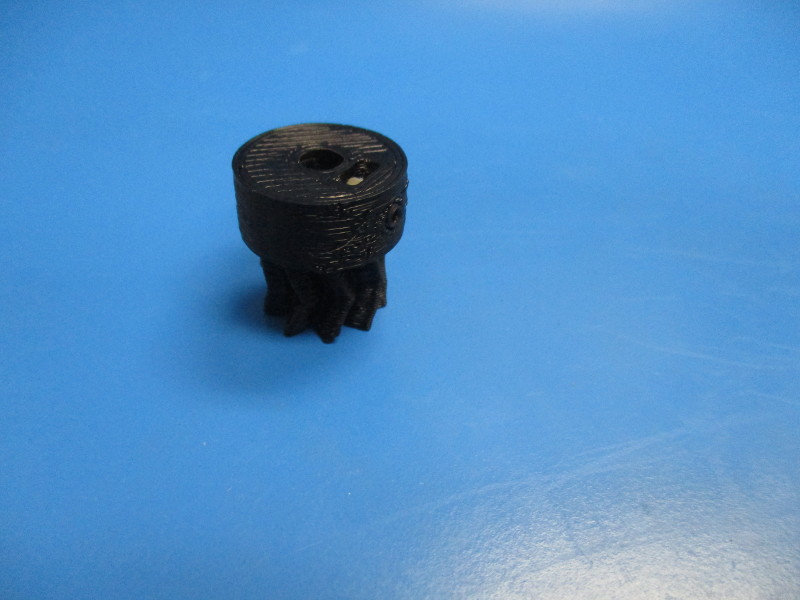
Small herringbone gear, black (PP-GP0062)
M3 set screw (HD-BT0012)
M3 nut (HD-NT0004)
Tools needed:

Lay the small herringbone gear on the gear face so the nut slot is facing up (see image for gear orientation)
Press nut into slot until holes in the small gear and the nut line up.
Install the set screw into the hole that is aligned with the nut using a 1.5mm driver
Thread until the head of the set screw is flush with the plastic
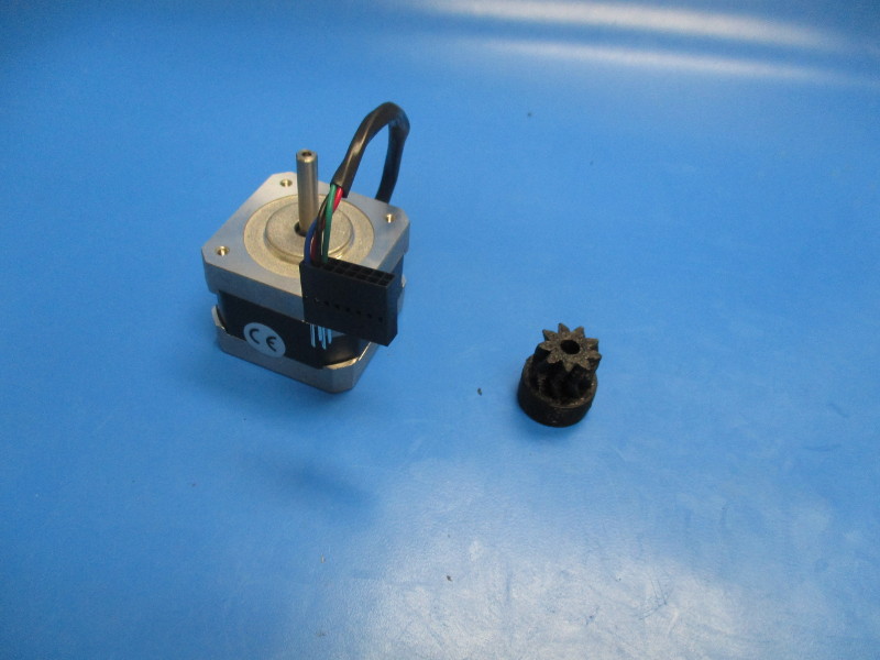
Gather parts
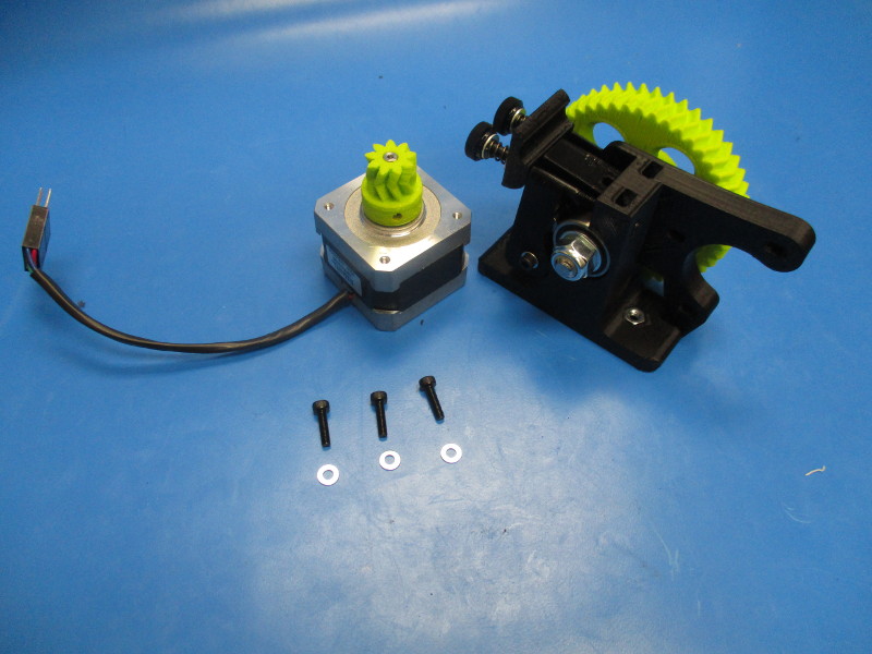
Half Height NEMA 17 Stepper Motor (EL-MT0017)
Small herringbone gear (assembled)
Tools needed:
Instructions:
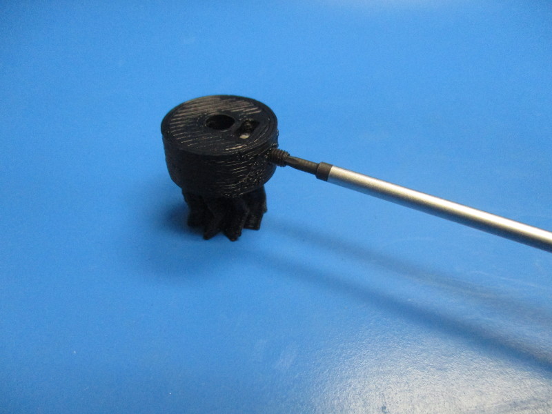
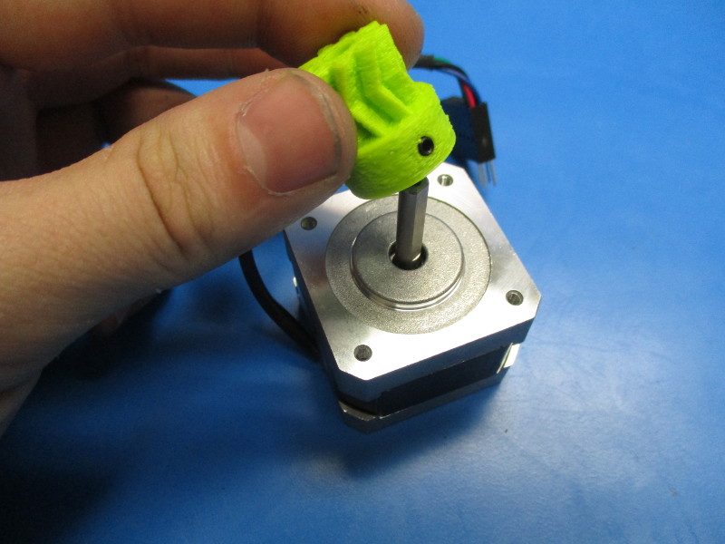
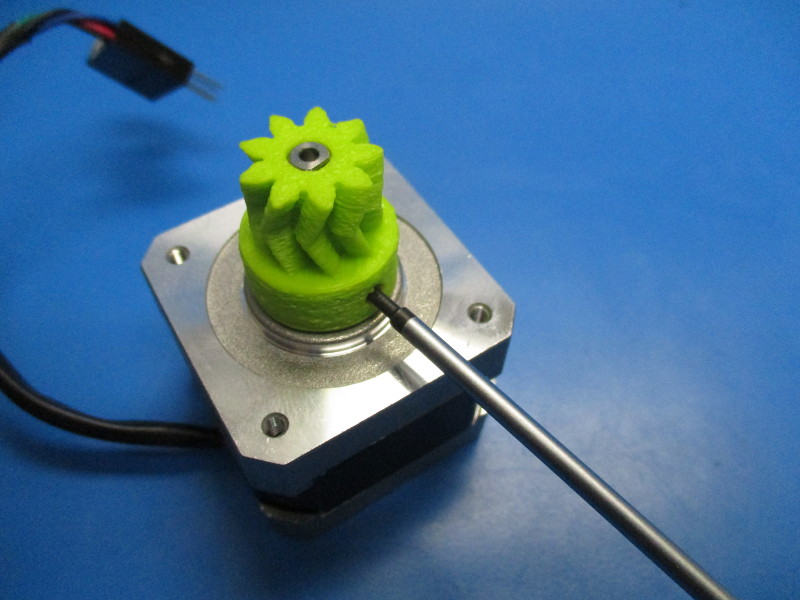
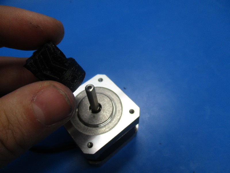
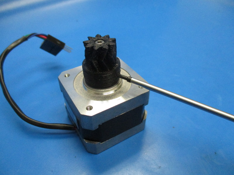
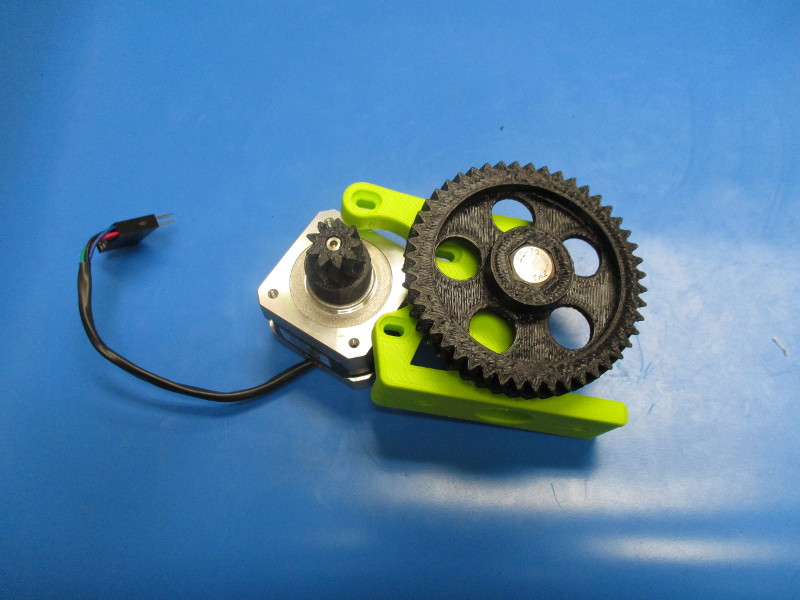
Install the small herringbone gear onto the shaft of the motor. Ensure that the set screw is aligned with the flat section of the shaft.
Finger tighten the set screw up to the shaft by using the 1.5mm driver.
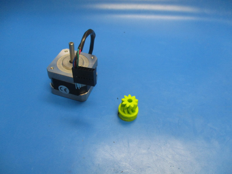

Installing the small black herringbone gear onto the motor
Gather parts
Half Height NEMA 17 Stepper Motor (EL-MT0017)
Small herringbone gear (assembled)
Tools needed: 1.5mm hex driver
Install the small herringbone gear onto the shaft of the motor. Ensure that the set screw is aligned with the flat section of the shaft.
Finger tighten the set screw up to the shaft by using the 1.5mm driver.
Gather parts
3x- M3x12 SHCS (HD-BT0039)
3x- M3 washer (HD-WA0001)
1x- Half Height NEMA 17 Stepper Motor with herringbone gear
1x- Extruder body (partially assembled)
Tools needed:
2.5mm hex driver
1.5mm hex driver
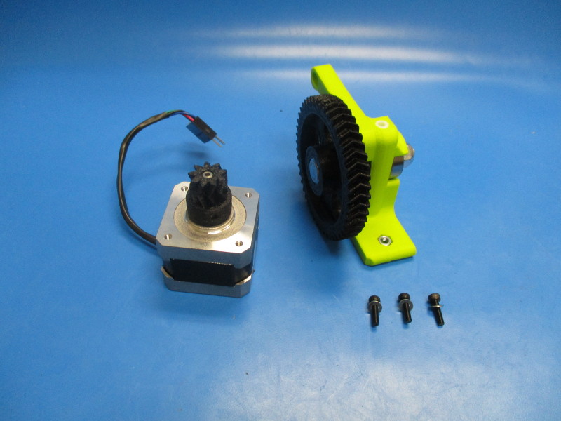
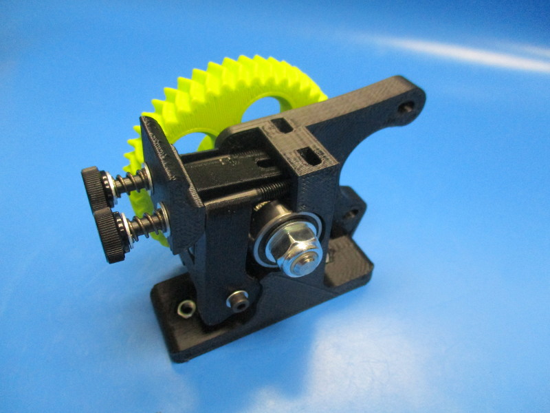
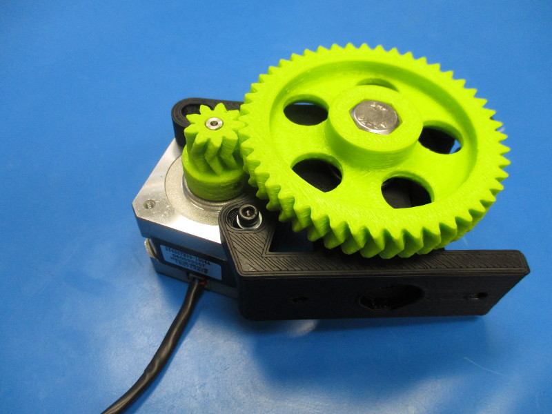
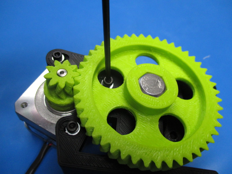
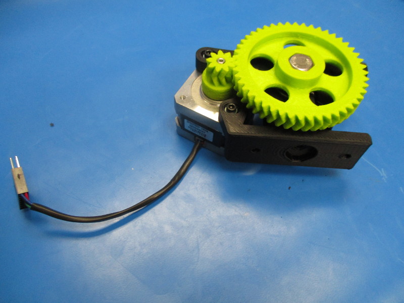
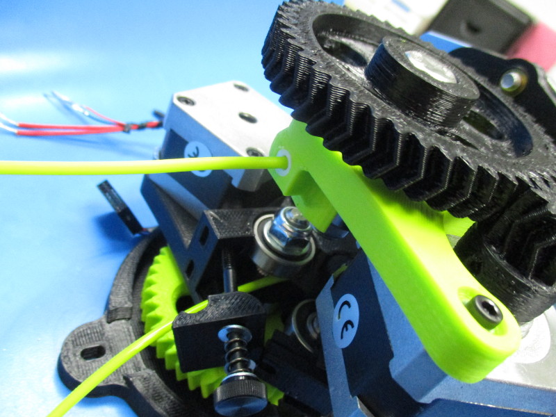
Mount the motor to the body (note the orientation of the motor)
Place the M3x12 SHCS with washers in the three holes that line up with the tapped holes in the motor
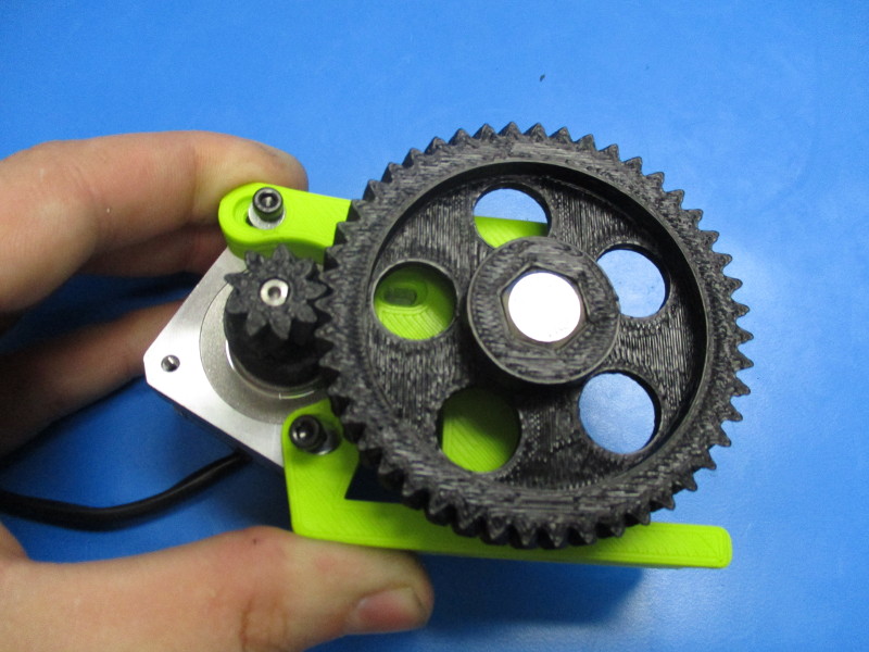
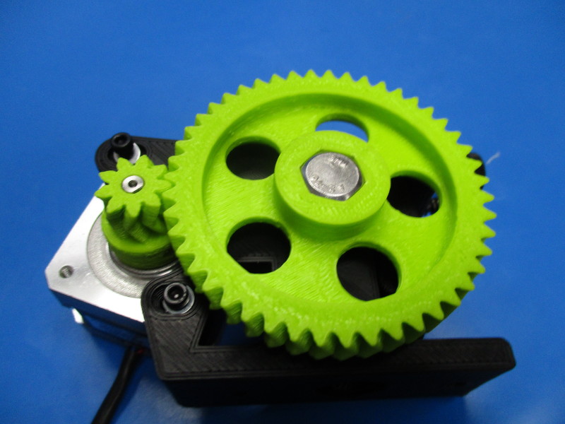
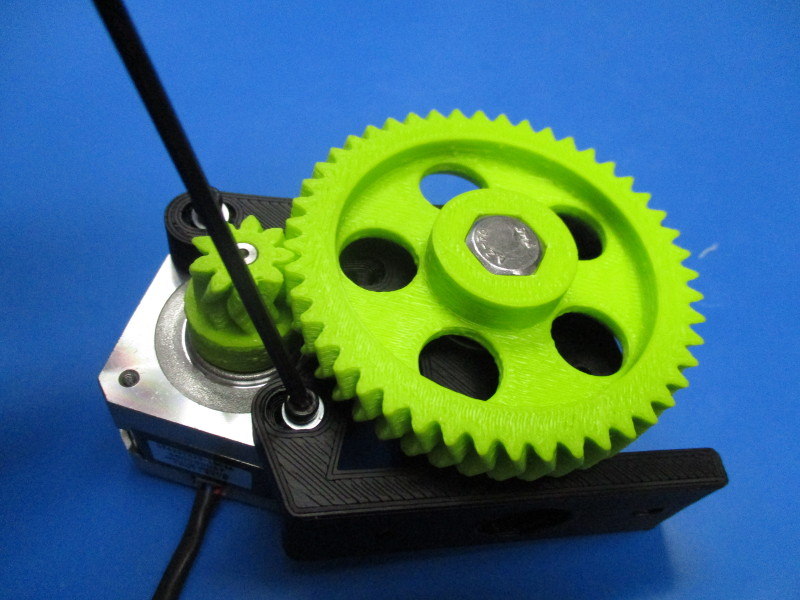
Note: the large gear and the small gear need to be mated together in a way that there is easy rotation but won't have any free movement known as “slap” between the gear teeth. To test for proper alignment of gears - tighten your screws down to 3 in*lbs, Hold the small gear firmly with your finger and thumb, and try to move the large gear back and forth to see if there is any small movement between the teeth of the gears. Rotate the large gear ¼ turn and repeat this process multiple times to ensure alignment. If there is movement the small gear and large gear need to be moved closer to each other. To do this you need loosen the M3 screws ¼ turn counter-clockwise and push the motor closer to the body. Repeat until you have desired the results, tighten screws once the fit is correct.)
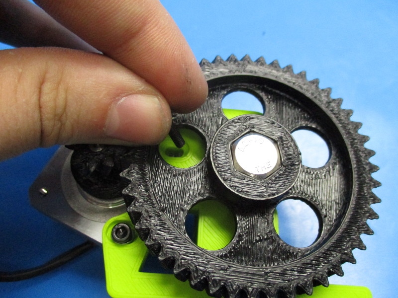
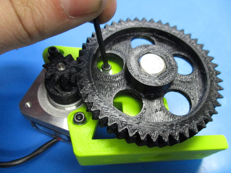
Tighten the set screw in the small herringbone gear to 3in*lbs


Gather parts
3x- M3x12 SHCS (HD-BT0039)
3x- M3 washer (HD-WA0001)
1x- Half Height NEMA 17 Stepper Motor with herringbone gear
1x- Extruder body (partially assembled)
Tools needed:
2.5mm hex driver
1.5mm hex driver
Mount the motor to the body (note the orientation of the motor)
Place the M3x12 SHCS with washers in the three holes that line up with the tapped holes in the motor
Note: the large gear and the small gear need to be mated together in a way that there is easy rotation but won't have any free movement known as “slap” between the gear teeth. To test for proper alignment of gears - tighten your screws down to 3 in*lbs, Hold the small gear firmly with your finger and thumb, and try to move the large gear back and forth to see if there is any small movement between the teeth of the gears. Rotate the large gear ¼ turn and repeat this process multiple times to ensure alignment. If there is movement the small gear and large gear need to be moved closer to each other. To do this you need loosen the M3 screws ¼ turn counter-clockwise and push the motor closer to the body. Repeat until you have desired the results, tighten screws once the fit is correct.)
Tighten the set screw in the small herringbone gear to 3in*lbs

Gather parts
Zero volt sense harness
M3x8 BHCS (HD-BT0104)
M3 lock washer (HD-WA0027)
Tools needed:
Instructions:
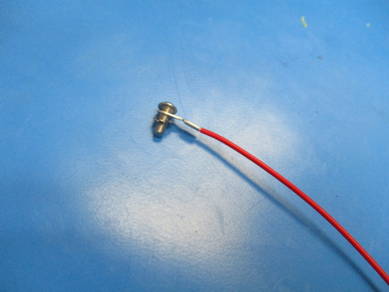
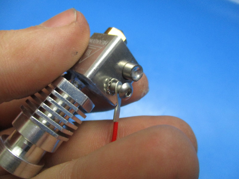
Install the Zero volt sense harness to the heater block part of the hot end with the hardware in the order, screw, harness, lock washer, heater block.
Torque to 5in*lbs


Gather parts
4x- M4x16 SHCS (HD-BT0046)
Dual mount plate
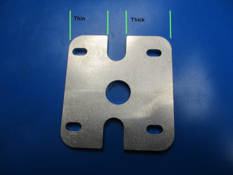
On the dual mount plate, there is a side that is thicker in width and one side that is thinner. (see image “mount plate”)
Orient the mount plate so that the Tick side is on the left.
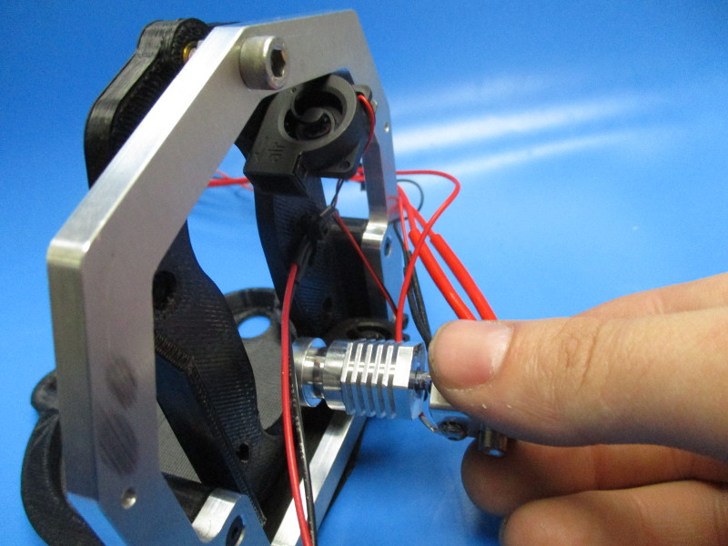
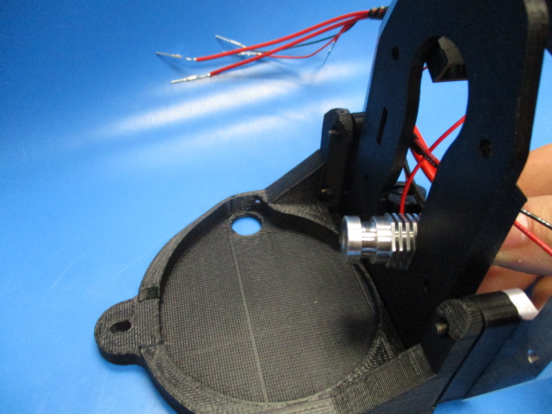
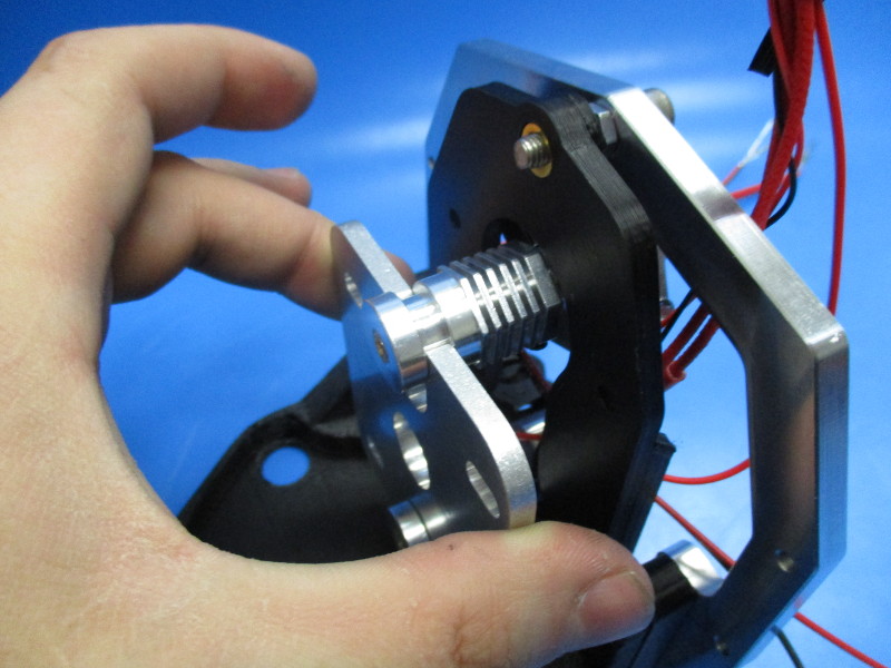
Hold the mount plate close to the extruder mount.
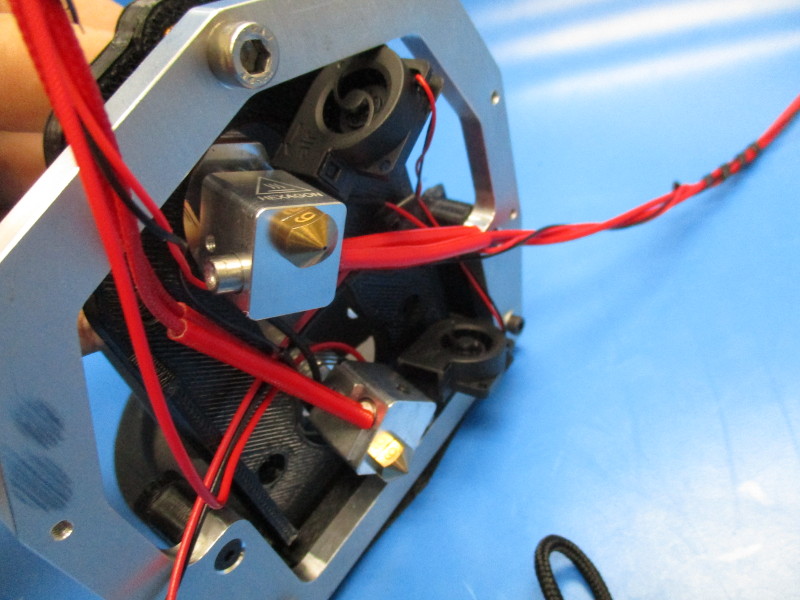
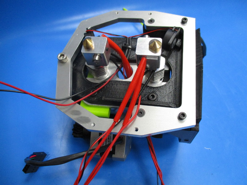
Slide the hot end with the ground attached through the center slot of the flex plate.
Slide the mount plate over the hot end.
Ensure the thermistor and heater cartridge are oriented upwards at an angle.
Slide the second hot end into the same slot at the top. Slide the end of the hot end into the slot in the mount plate.
Push the mount plate up against the flex plate.
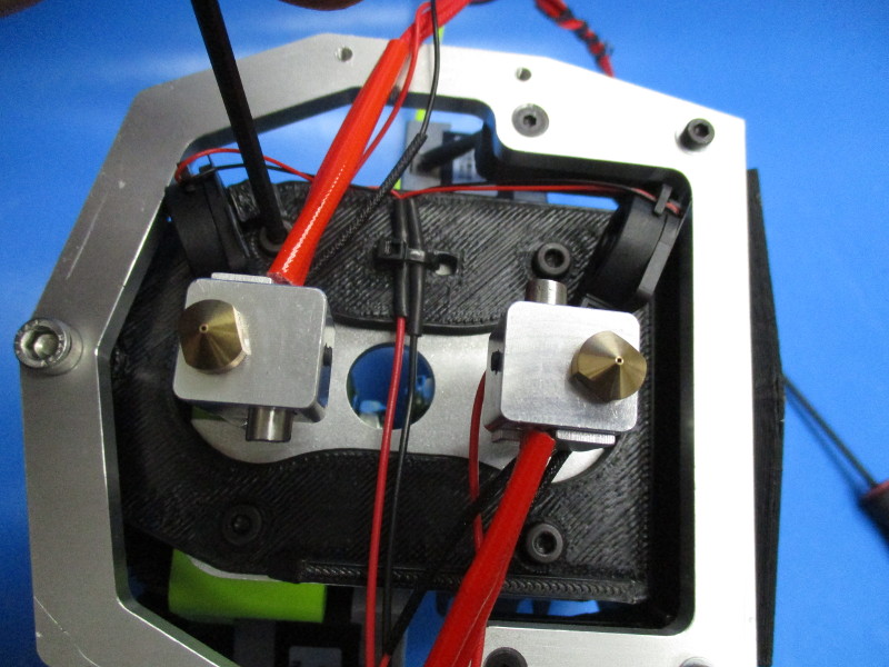
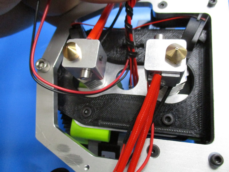
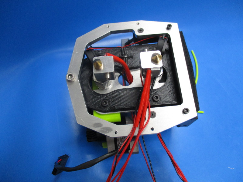
Orient the assembly to show the hot end nozzles.
Install the four M4x16 SHCS into the holes as shown (see image “hole location”)


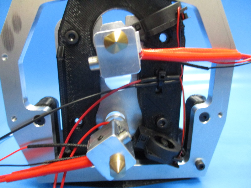
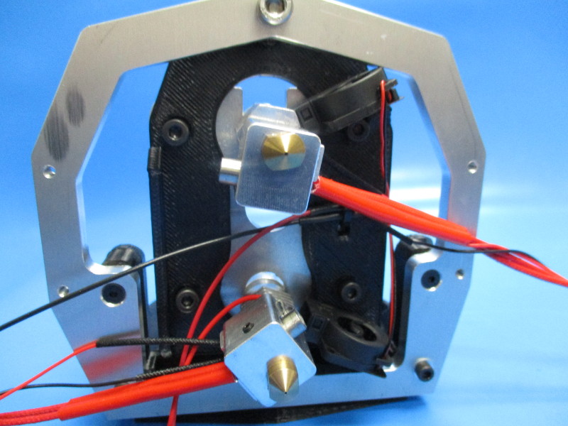
Tools needed:
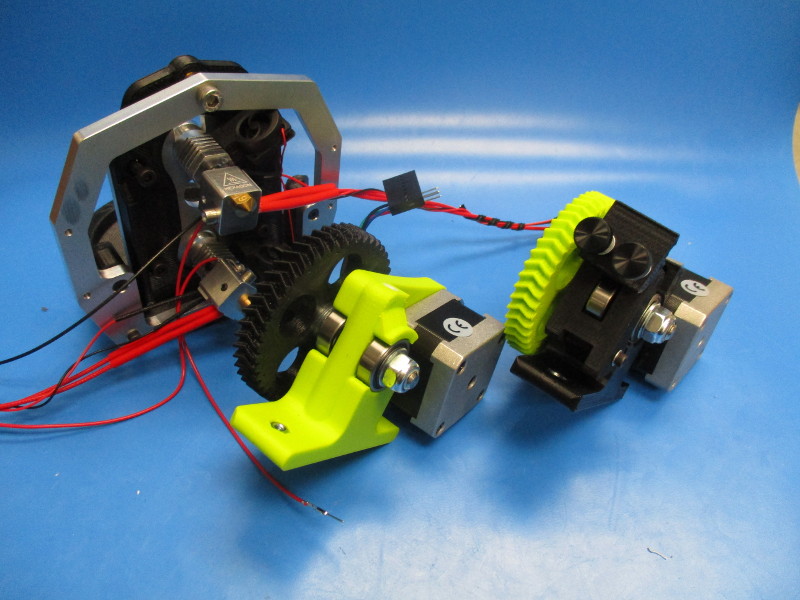
Attach the regular extruder body to the mount plate. (see image “Regular extruder body” for part orientation)
The M4 screws and the hot end should slide into the corresponding holes.
Finger tighten the M4 screws to secure the body in place.
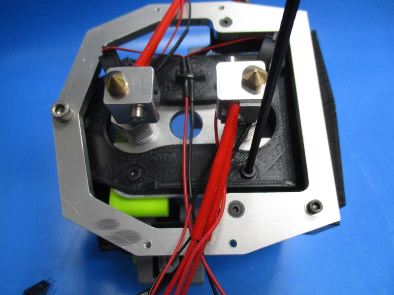
Attach the flexystruder body to the mount plate. (see image “Flexystruder body” for part orientation)
Finger tighten the upper two M4 screws to secure the flexystruder body.
Check to see if the hot ends are square with each other.
Torque the M4x16 screws to 8in*lbs
Feed 150mm of ABS filament into the regular body to check alignment.
Feed 150mm of nylon filament into the flexystruder body to check alignment.
(If filament snags, loosen the screws and move the mount plate until snagging doesn't occur)


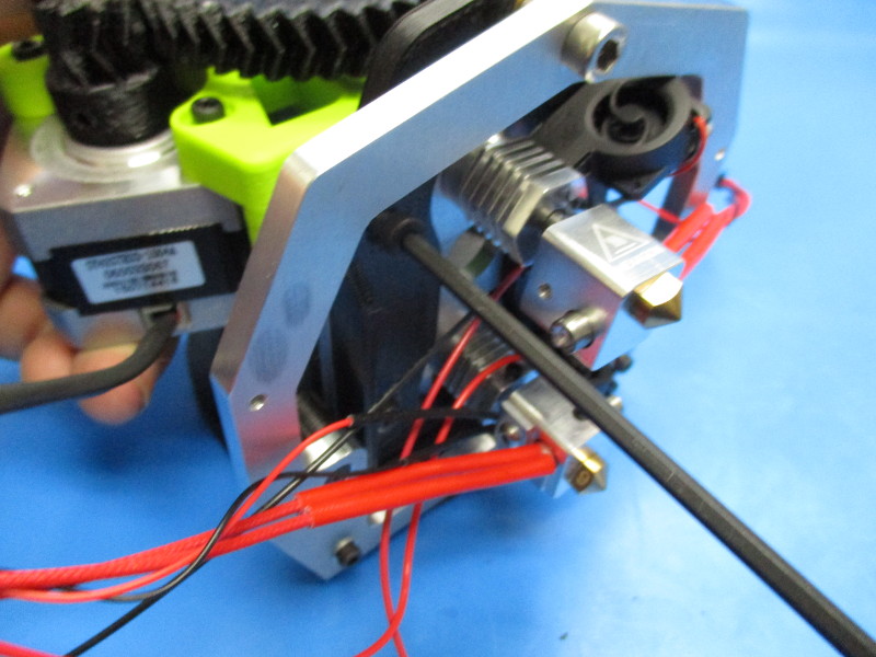

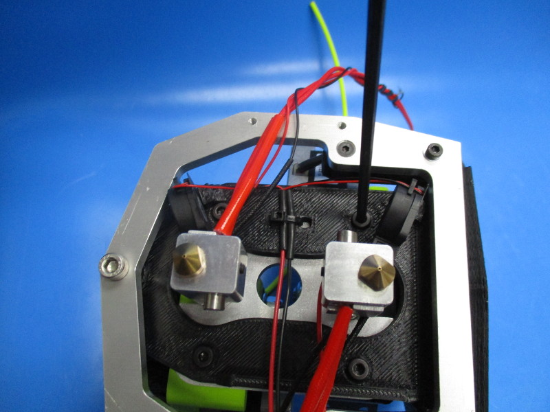
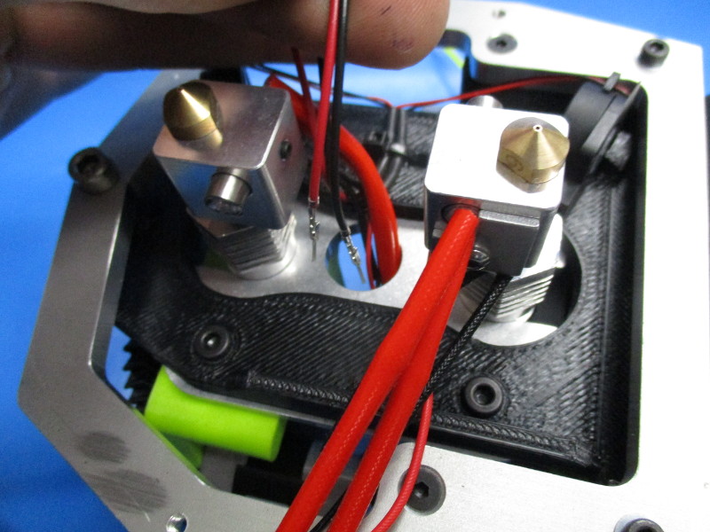
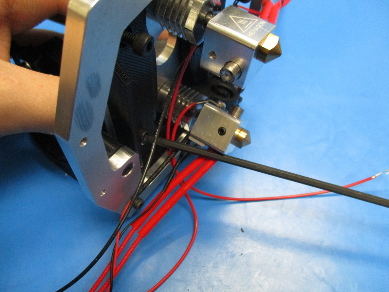
Feed the front hot end harnesses through the center hole in the mount plate and pull through.
Feed the micro blower harness through the same hole and pull through.
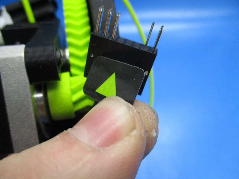
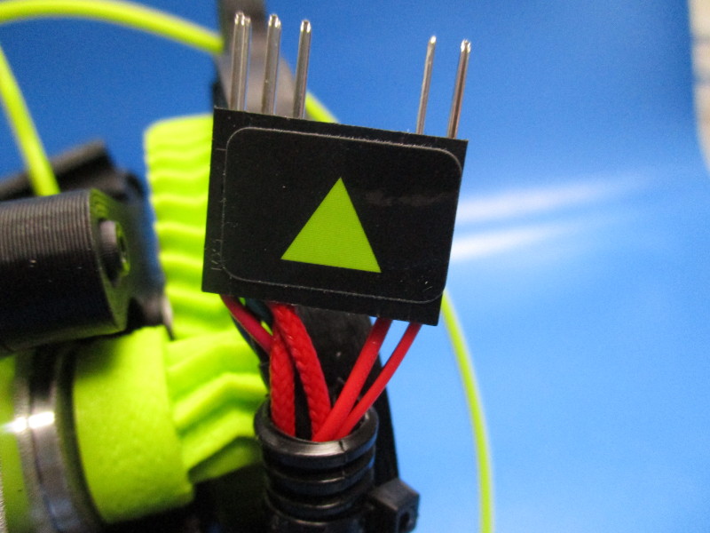
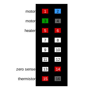
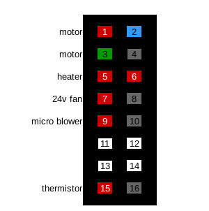
Connect the hot end harnesses and micro blower harness into the 16pin connector coming from the flexystruder.
(see image “pin positions”)
Heater cartridge –
Red: pin 5
Red: pin 6
Thermistor-
Red: pin 15
Black: pin 16
Micro blower-
Red: pin 9
Black pin 10
Ensure the harnesses don't get twisted around the motor harness.

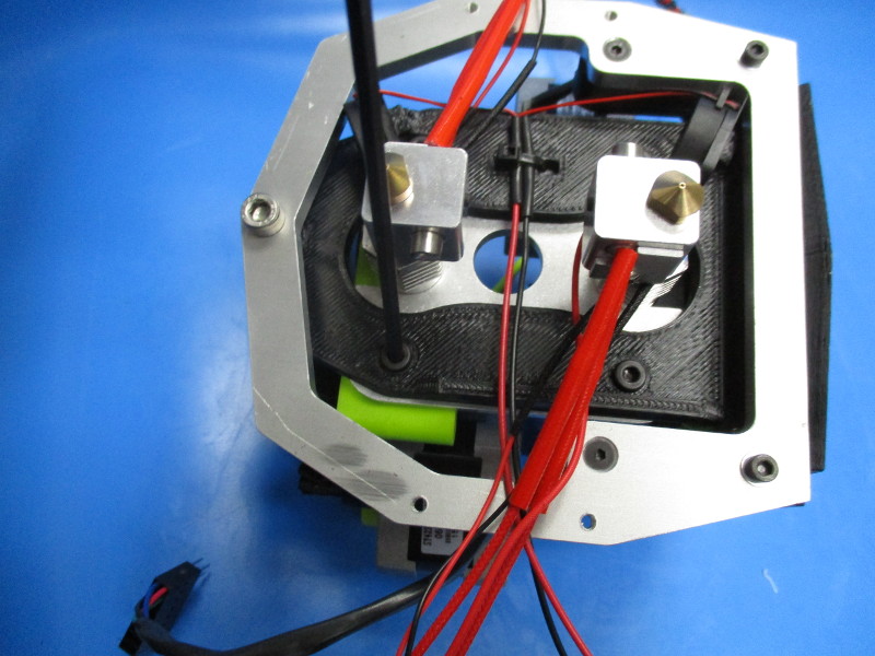
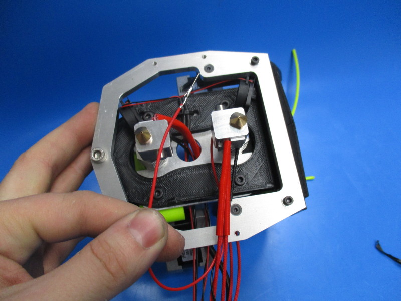
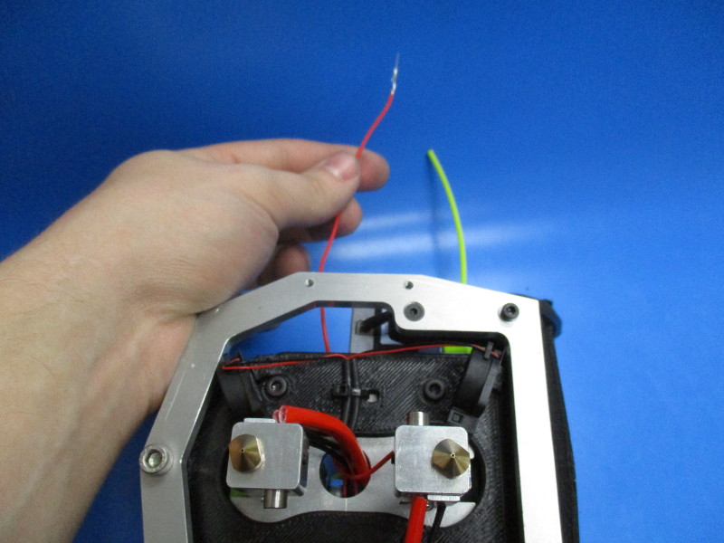
Feed the zero volt sense from the back hot end through the center hole in the mount plate. Pull through. (note the side the harness is on after pulling through)
Connect it to the 16pin connector, in position 14, coming from the regular extruder motor harness.
Feed the back hot end harnesses through the center hole in the mount plate and pull through.
Connect the hot end harnesses into the 16pin connector coming from the flexystruder.
(see image “pin positions”)
Heater cartridge-
Red: pin 5
Red: pin 6
Thermistor -
Red: pin 15
Black: pin 16

Preparing the 24v fans
Gather parts
2x- 40mm fan duct for dual
1x- 24v fan harness
4x- M3x20 SHCS (HD-BT0007)
4x- M3 washer (HD-WA0001)
Tools needed:
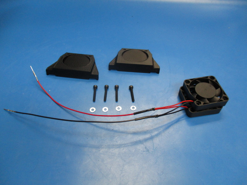
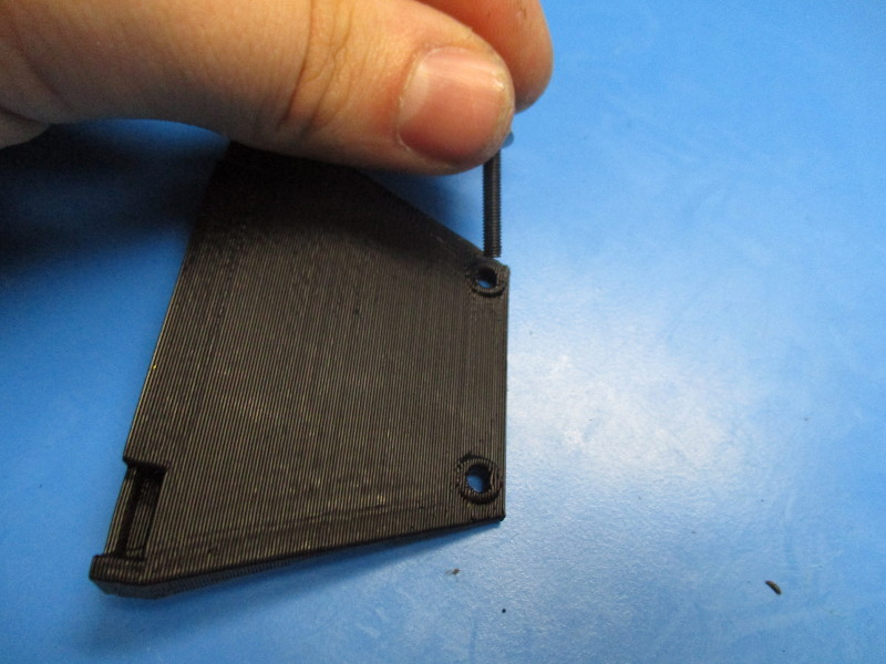
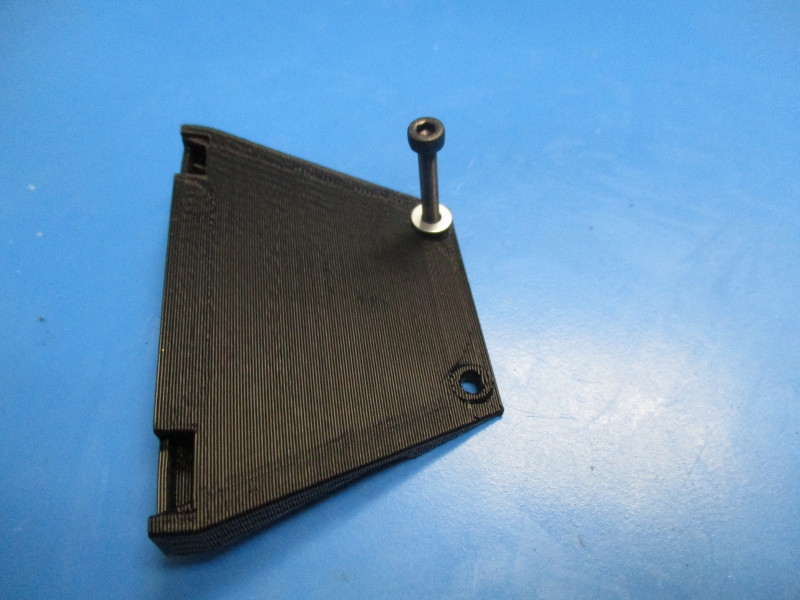
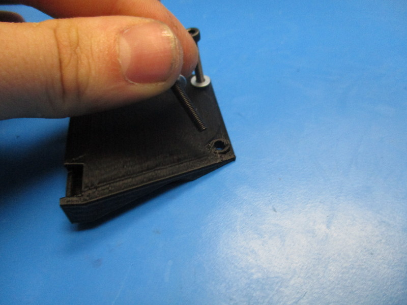
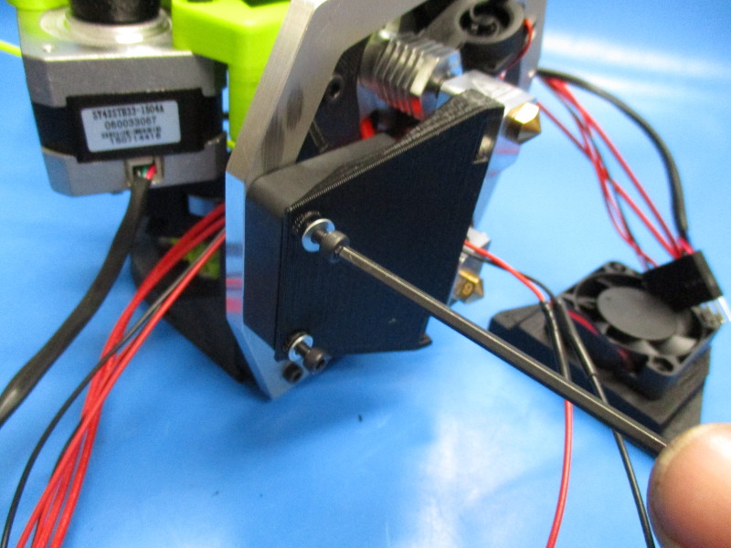
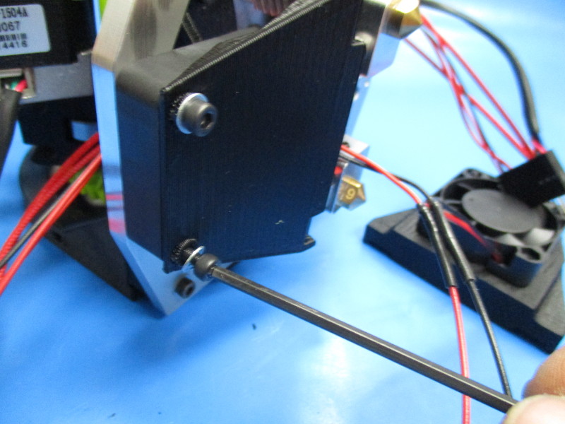
Thread two M3x20 SHCS with washers onto the holes of the fan duct. (see image “fan duct” for part orientation and hole location)
Thread the two M3 screws until they are halfway though the fan duct.
Repeat processes to second fan duct
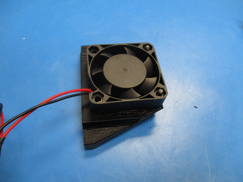
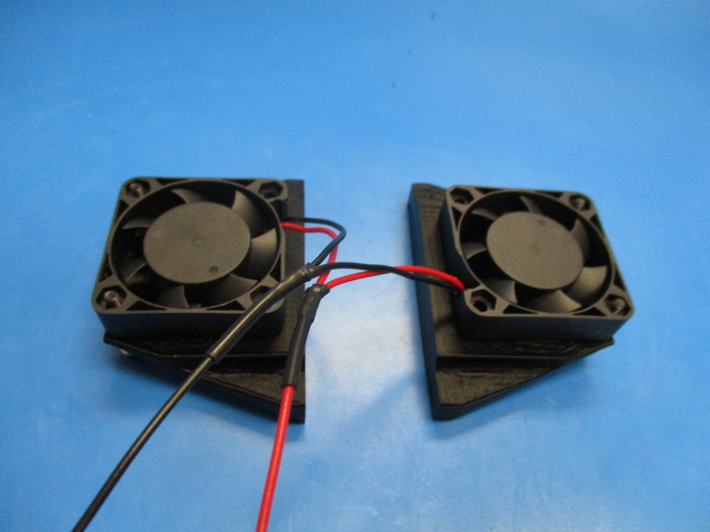
Place one of the 24v fans from the harness over the M3 screws. (see image “placing fan” for fan orientation)
Place the second fan from the fan harness onto the second fan duct. (see image “second fan” for fan orientation)
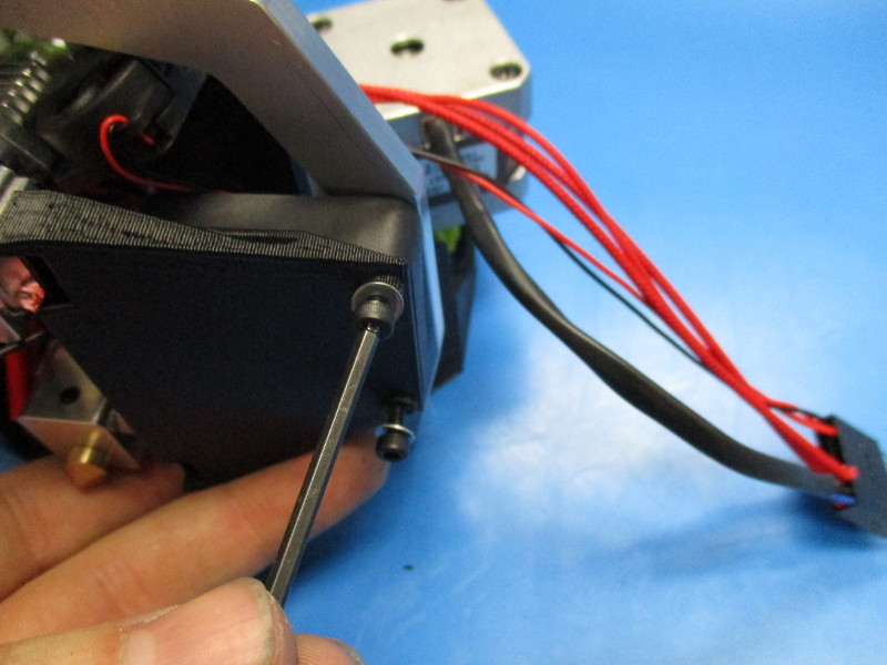
Attach the fan ducts with fans to the lower bracket.
Secure the fan duct onto the lower bracket. Torque to 3in*lbs
Repeat process on other side.
Feed the 24v fan harness through the center hole of the mount plate and connect it to the front 16pin connector.
24v fan harness:
Red: pin 7
Black: pin 8


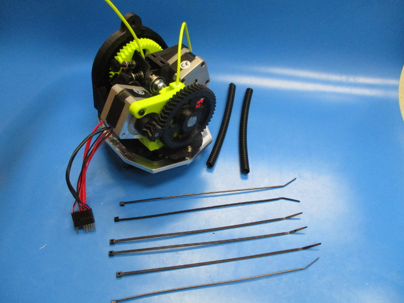
Installing panduit
Gather parts
2x- 125mm 1/4in panduit (EL-MS0073)
6x- Cable tie (HD-MS0058)
Instructions:
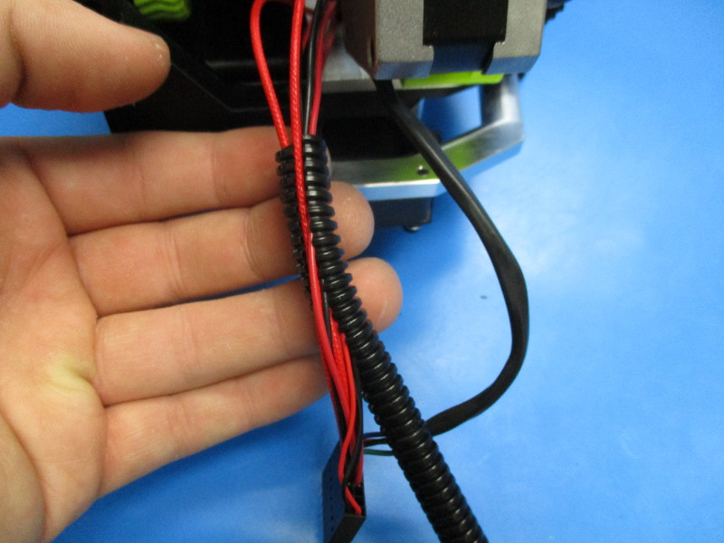
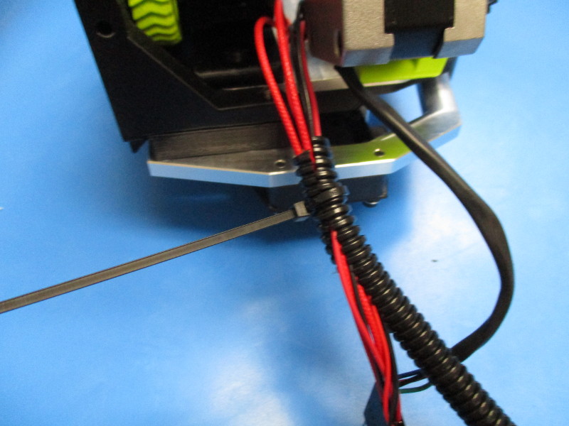
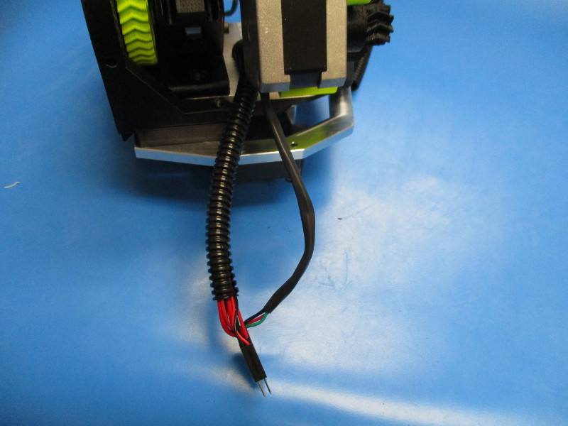
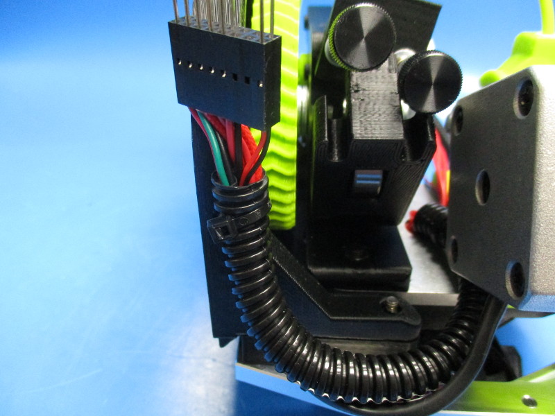
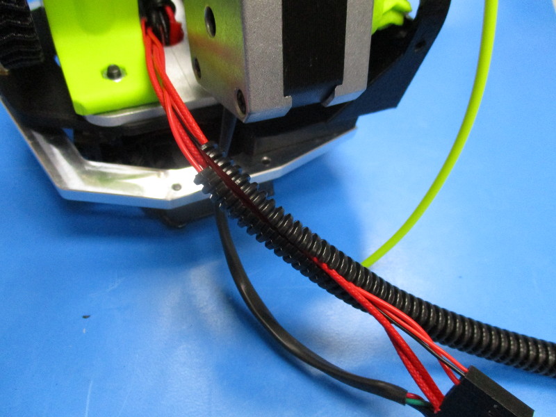
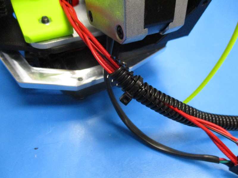
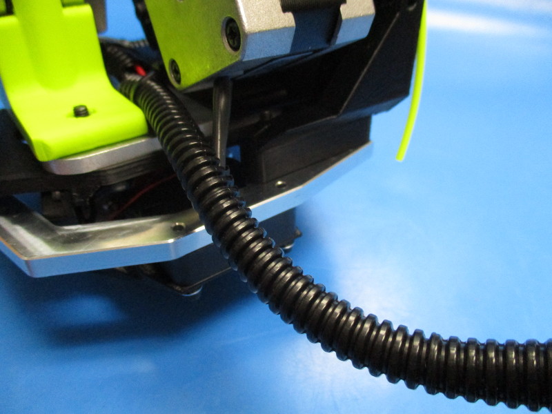
Wrap a section of panduit around the wire harnesses (not the motor harness). Cable tie 10mm from the end of the panduit. Clip excess cable tie. Slide the panduit to the center hole of the mount plate. Encase the rest of the harnesses in the panduit. Insert the motor harness into the panduit.
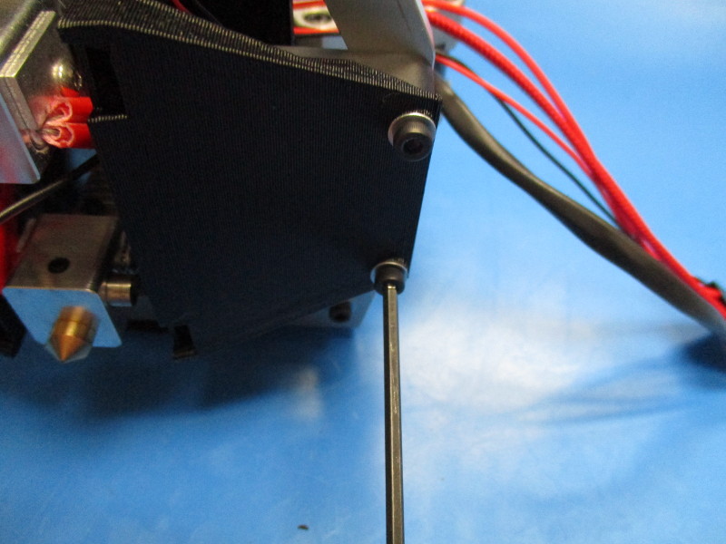
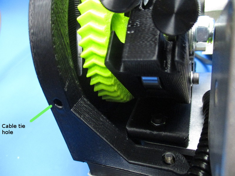
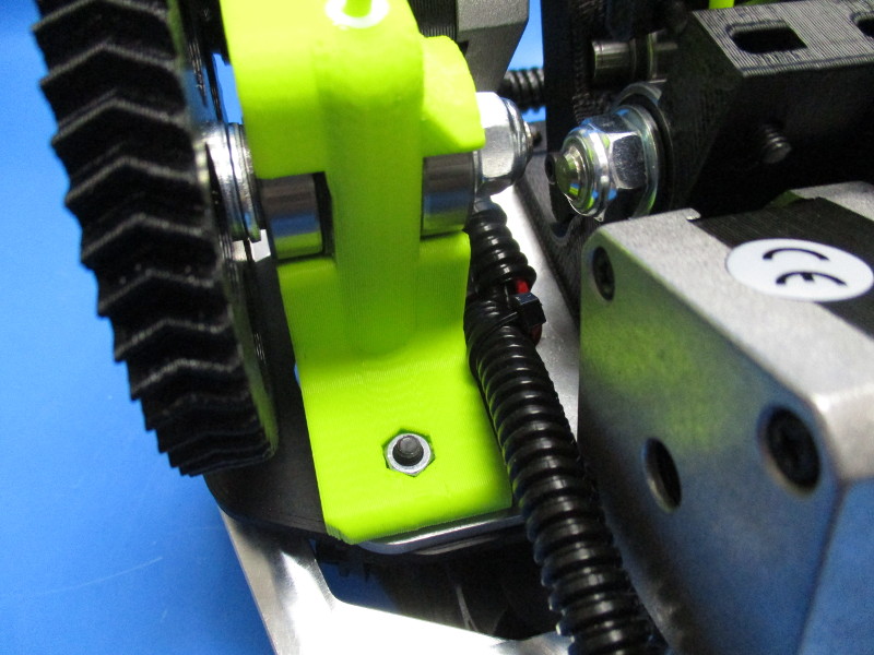
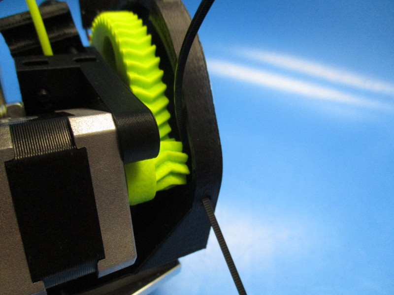
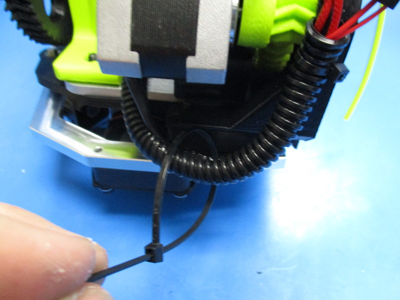
Run a cable tie behind the Large herringbone and through the cable tie hole. (see image “cable tie hole” for location)
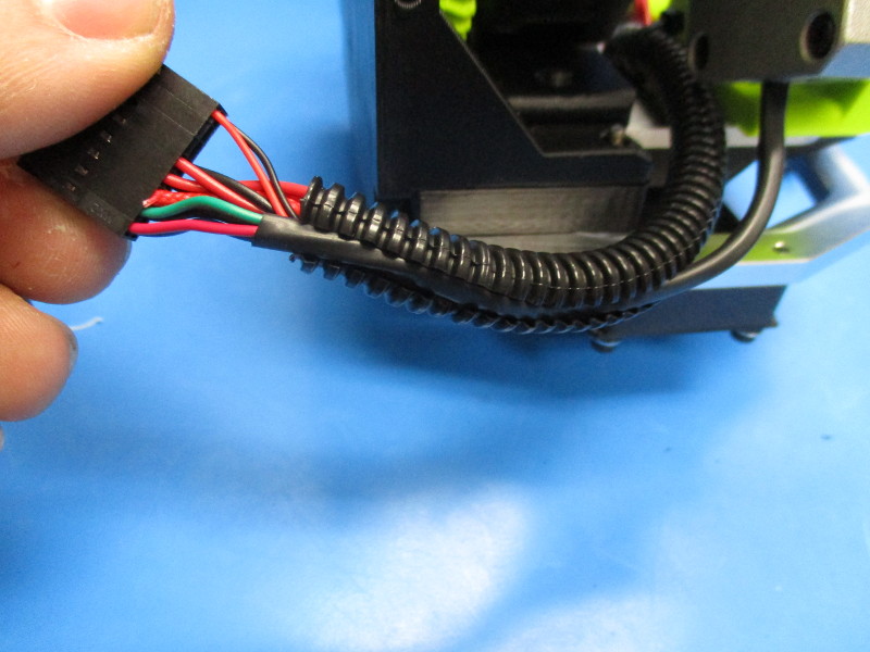
Secure the 16pin connector end to the extruder mount and clip excess cable tie.
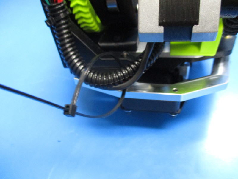
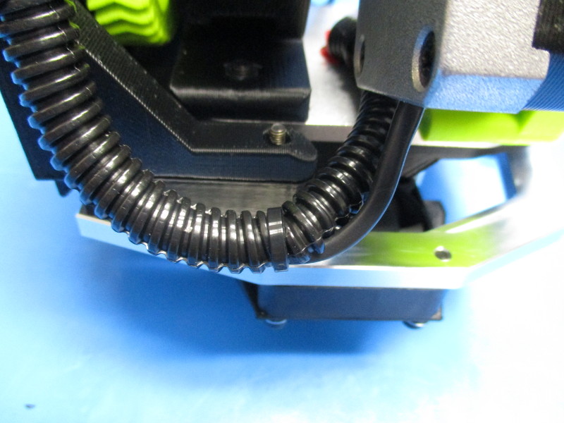
Cable tie the middle of the panduit and clip.
Repeat the cable tie process on the other side of the extruder.


Gather parts
Instructions:
Apply Arrow direction sticker to the 16pin connectors on the pin 1 side