Open HardwareAssembly Instructions
Guides for installation and assembly of the LulzBot line of products made by FAME 3D LLC.
Guides for installation and assembly of the LulzBot line of products made by FAME 3D LLC.
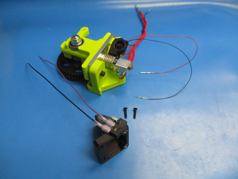
Gather parts:
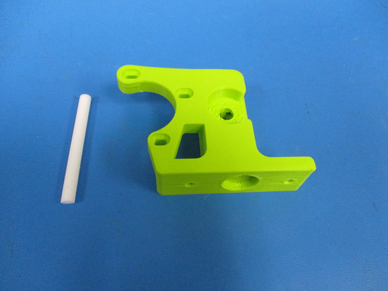
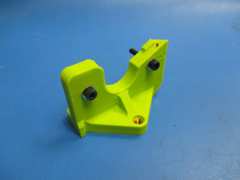
Flexystruder body (PP-MP0200)
65mm of PTFE tubing (HD-TB0006)
Tools needed:
Drill press
6.5mm drill bit
3.5mm drill bit
8mm drill bit
3mm thick metal rod
Precision knife
Instructions:
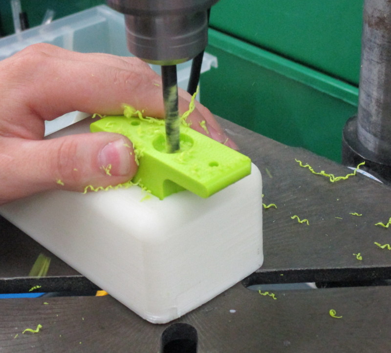
Starting at the bottom of the body, drill the out hole, that runs the length of the body, using the 6.5mm drill bit.
Press a 65mm long piece of PTFE tubing into the drilled hole through the bottom. The PTFE tubing needs to be flush with the indented hole.
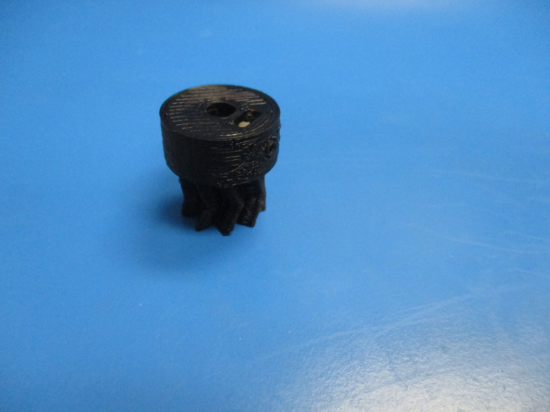
Note orientation of body.
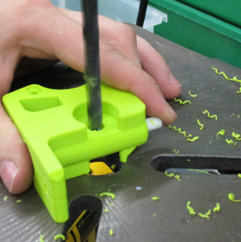
Drill the hobbed bolt hole out using the 8mm drill bit.
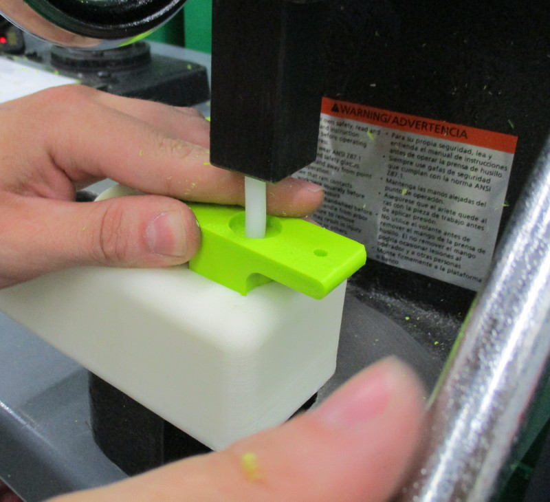
Drill the PTFE tubing out using the 3.5mm drill bit through the bottom of the body.
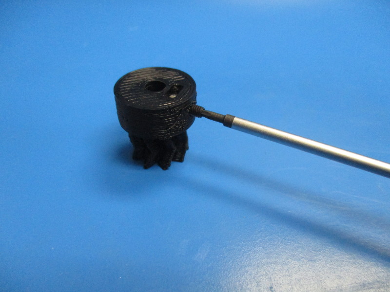
Slide the 3mm rod into the PTFE tubing.
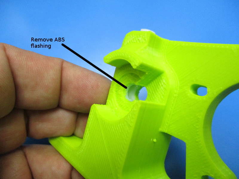
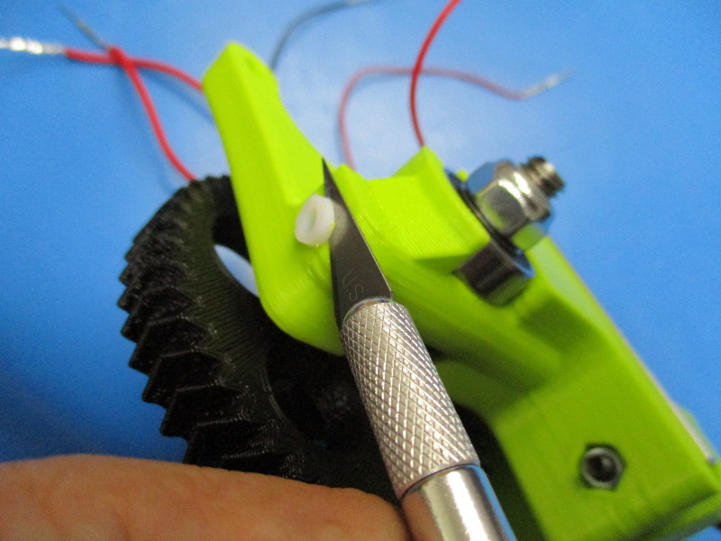
Clean out the flashing in the hobbed bolt hole using the precision knife.

Gather parts
Instruction:
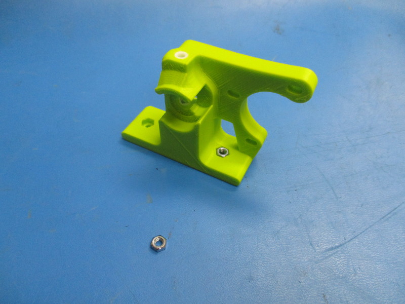
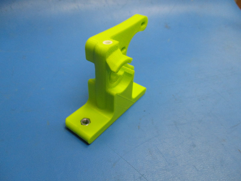
Insert both M4 nuts into the hexagon shaped socket at the base of the flexystruder body.

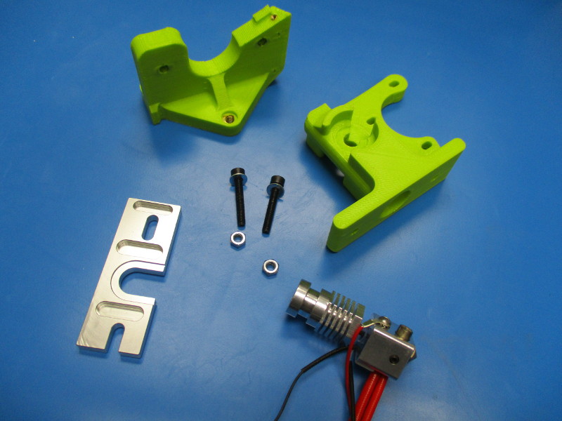
Gather parts-
Mini extruder mount (assembly)
Mount plate (PP-MP0137)
0.6 Hot end assembly
2x- M4x 25 SHCS (HD-MS0229)
2x- M4 washer (HD-WA0005)
Tools needed: - 3.5mm hex driver
Instructions:
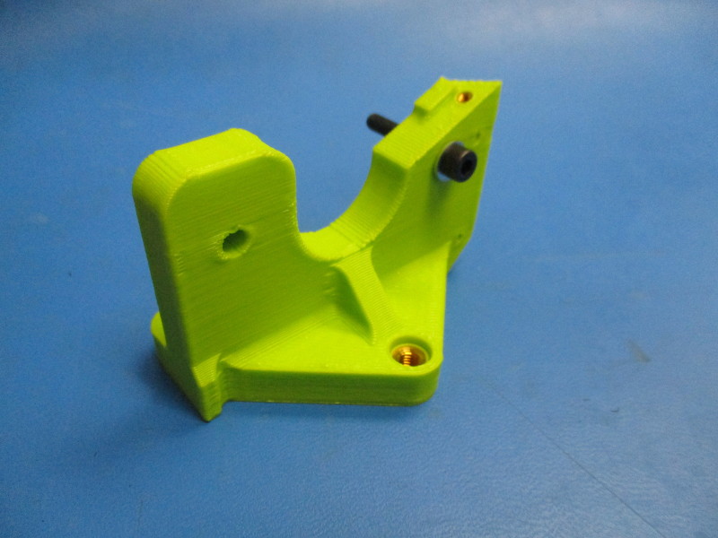
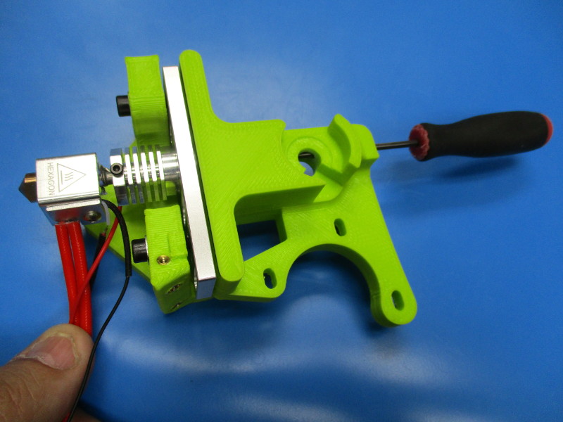
Insert the M4x25 screws with washers into the 4mm holes on either side of the PTFE tubing.
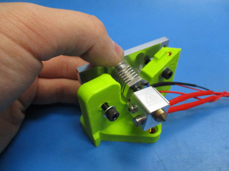
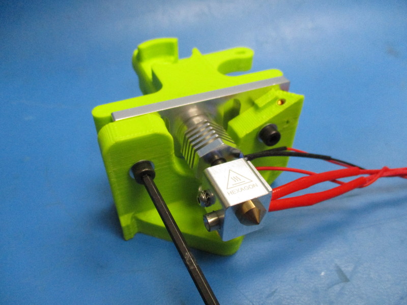
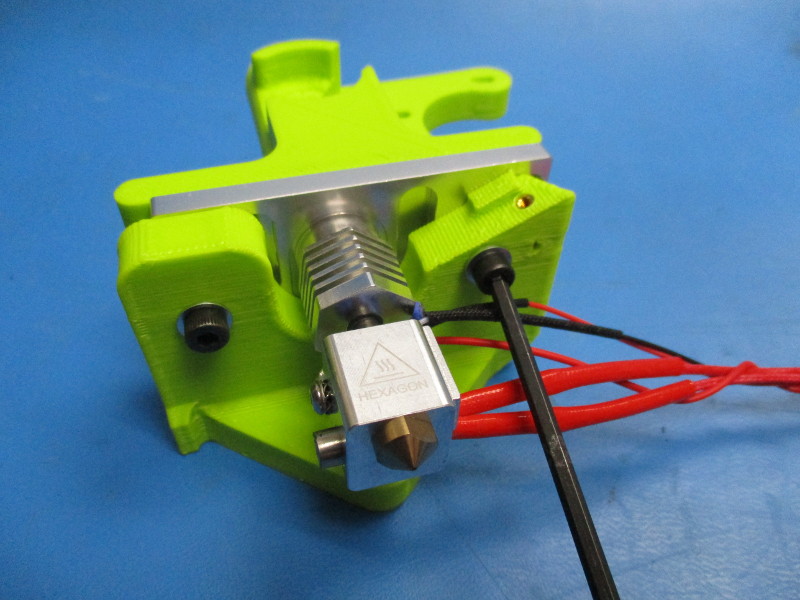
Install the mount plate over the deep groove on the hot end.
Install the hot end with the mount plate onto the extruder mount.
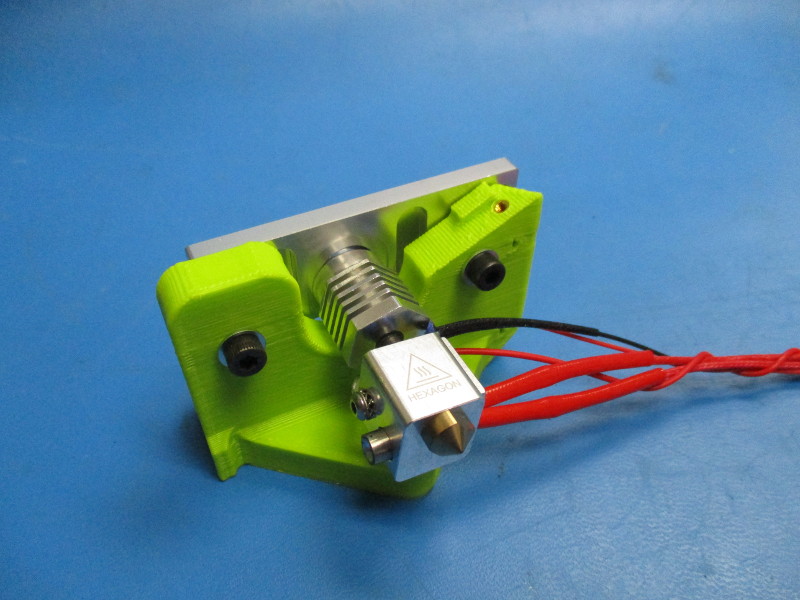
Install the flexystruder body onto the extruder mount. The M4x25 screws will line up with the 5mm holes that have the M4 nuts installed. Finger tighten.
Insert the 2.5mm hex driver down the PTFE tubing to align the body with the hot end. There shouldn't be any resistance when the 2.5mm driver reaches the hot end.
Torque the M4x25 screws to 10in*lbs.
Insert the 2.5mm driver down the PTFE tubing again to make sure the alignment didn't shift. (If shift occurs, repeat alignment steps)


Installing Large herringbone gear
Gather parts
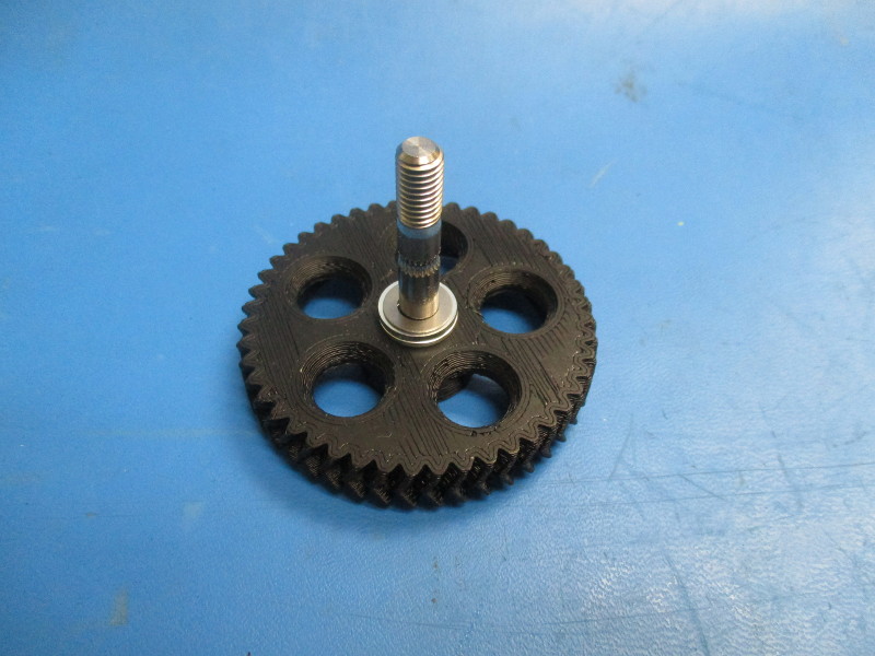
1x- Large herringbone, black (assembly)
1x- extruder washer (PP-GP0060)
2x- 608 bearing (HD-MS0282)
3x- M8 washer (HD-WA0006)
1x- 0.5mm shim (HD-WA0008)
1x- M8 nyloc nut (HD-NT0002)
Tools needed:
13mm wrench
Precision knife
Instructions:
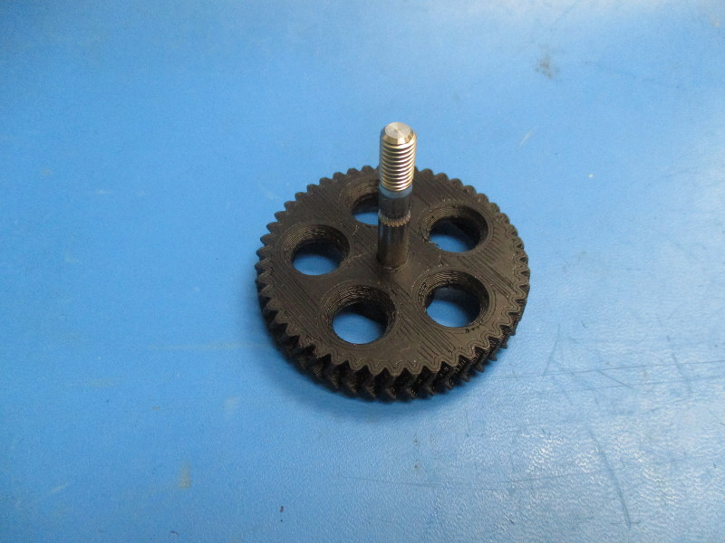
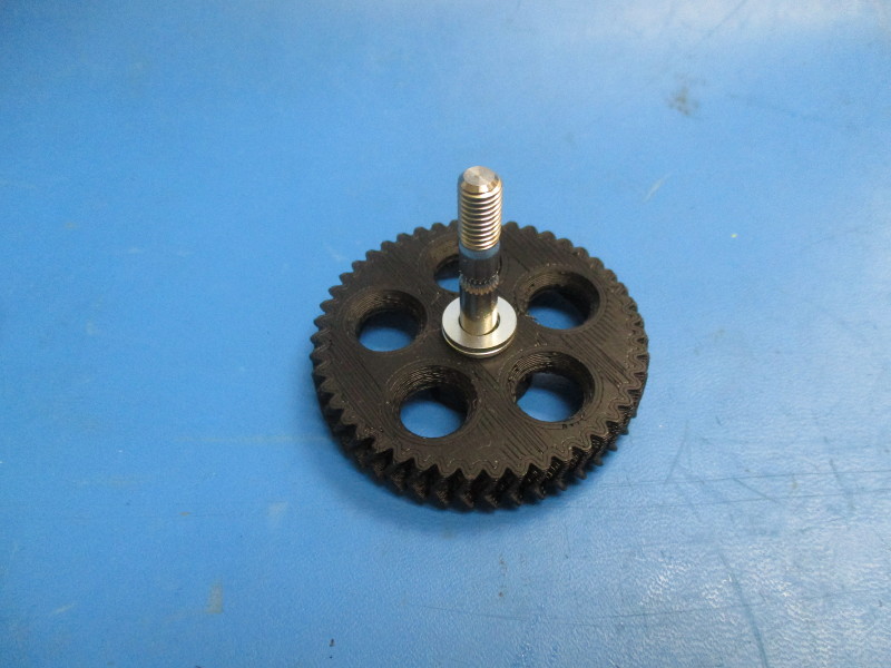
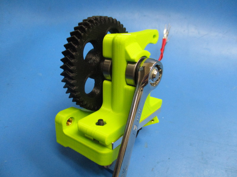
Install two M8 washers and one 0.5mm shim onto the hobbed bolt that is inserted into the large herringbone hear.
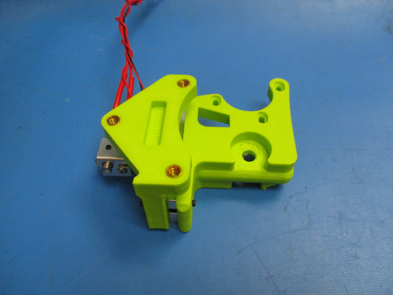
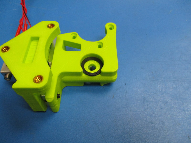
Lay the assembly onto its face. Install the extruder washer into the bearing pocket Install a 608 bearing on top of the extruder washer.
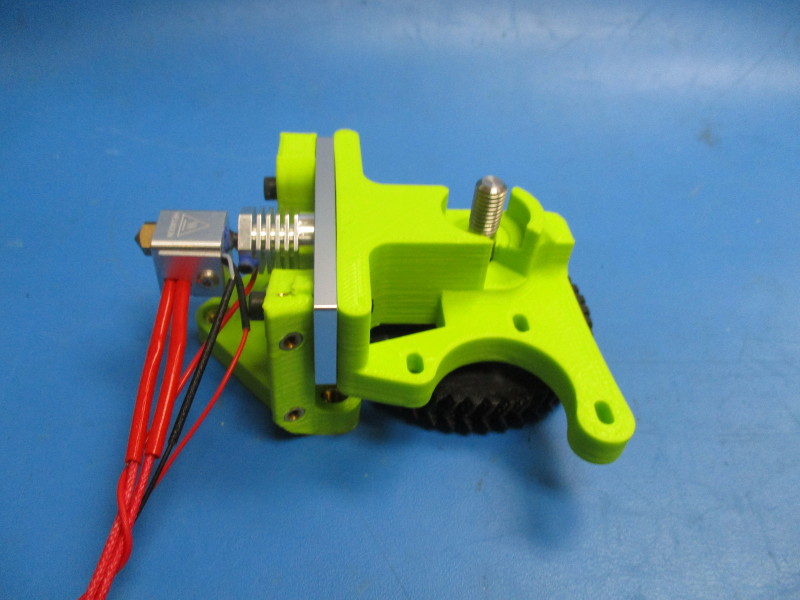
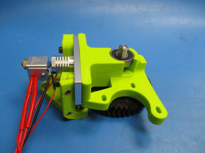
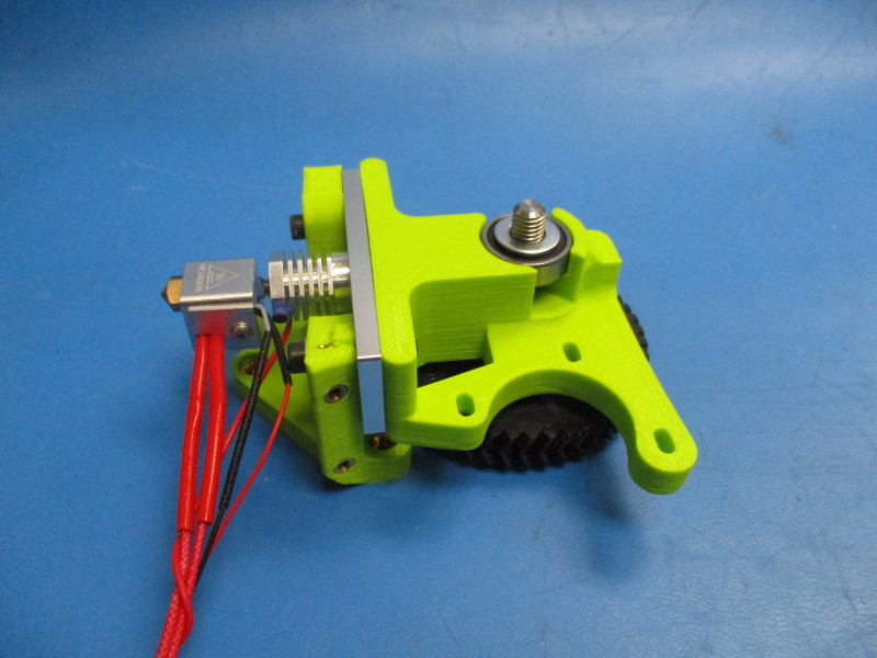
Install the large herringbone gear onto the flexystruder body by inserting the hobbed bolt through the bearing and body.
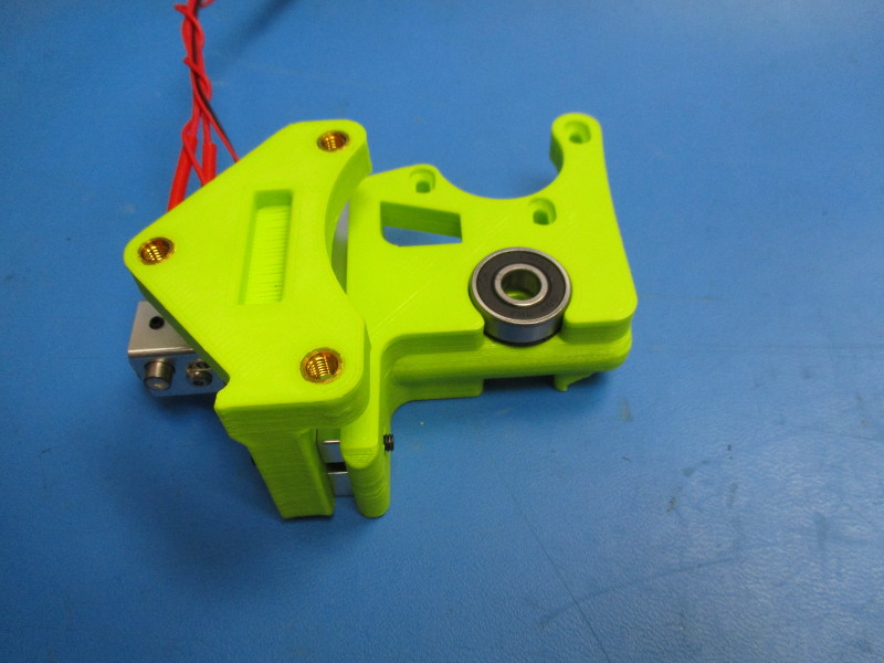
Flip the assembly over so the threaded portion of the hobbed bolt is visible. Install the second 608 bearing onto he hobbed bolt. Press the bearing down so that it sits in the bearing pocket.
Install a M8 washer on top of the bearing. Install the M8 nyloc nut onto the threaded portion of the hobbed bolt.
Tighten the M8 nut using the 13mm wrench. The washer under the nut should not move freely or with slight force applied.
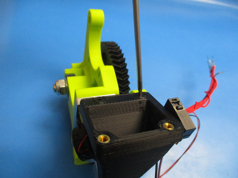
Cut off the excess PTFE tubing sticking out of the top.


Gather parts
M2x6 SHCS (HD-MS0230)
Micro blower harness (assembly)
Tools needed:
Instructions:
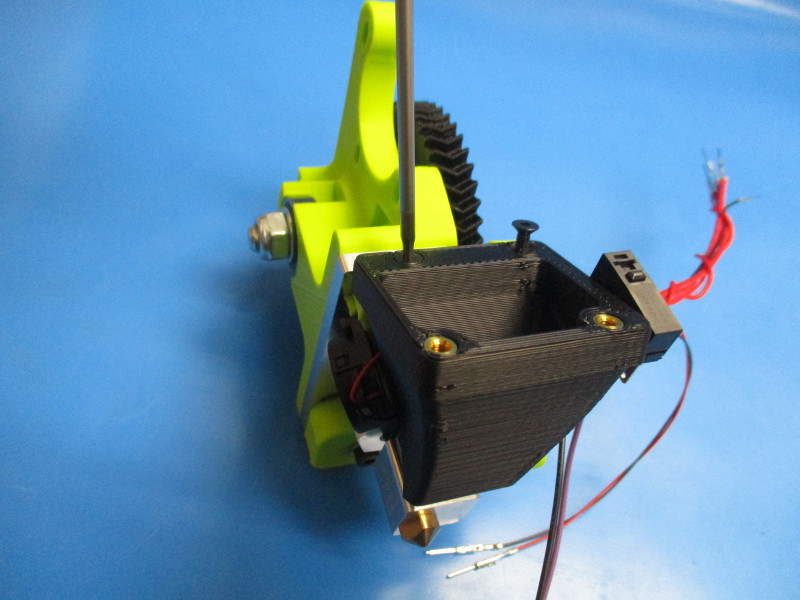
With the arrow on the micro blower pointing left, insert the M2x6 screw into the top right hole. Install the micro blower by fastening the M2x6 into the threaded insert on the extruder mount.

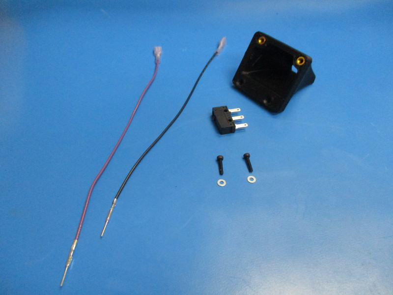
Gather parts
Extruder fan mount (assembly)
Limit switch (EL-SW0022)
2x- M2x10 SHCS (HD-BT0107)
2x- M2 washer (HD-WA0012)
Tools needed:
Instructions:
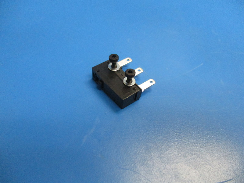
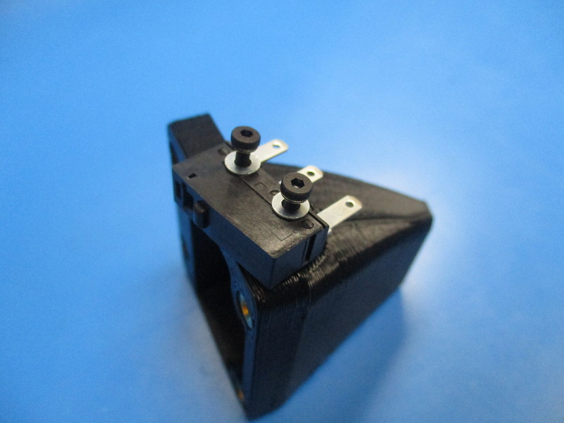
Orient the switch so the connection prongs are on the right and the push switch is at the top. Install the M2x10 screws, with washers, into the holes near the prongs.
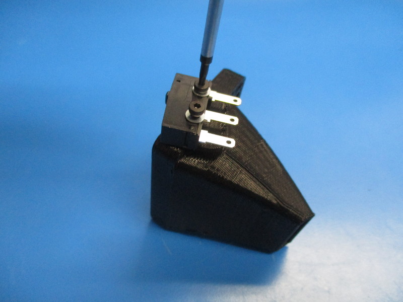
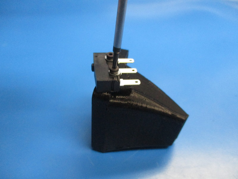
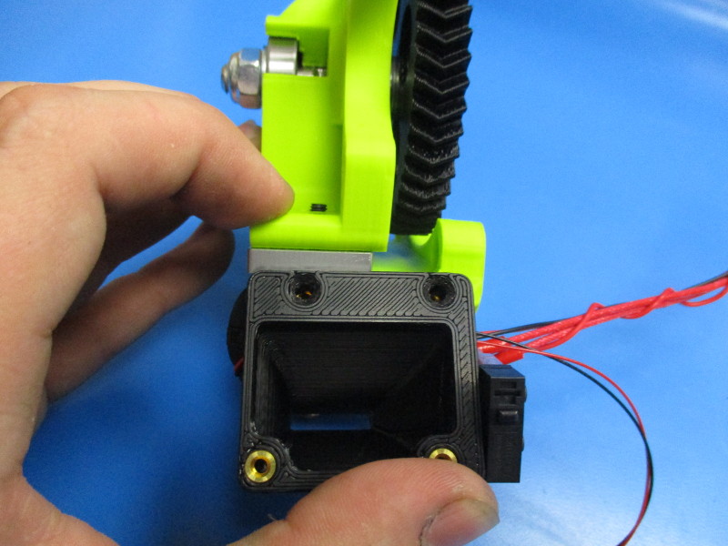
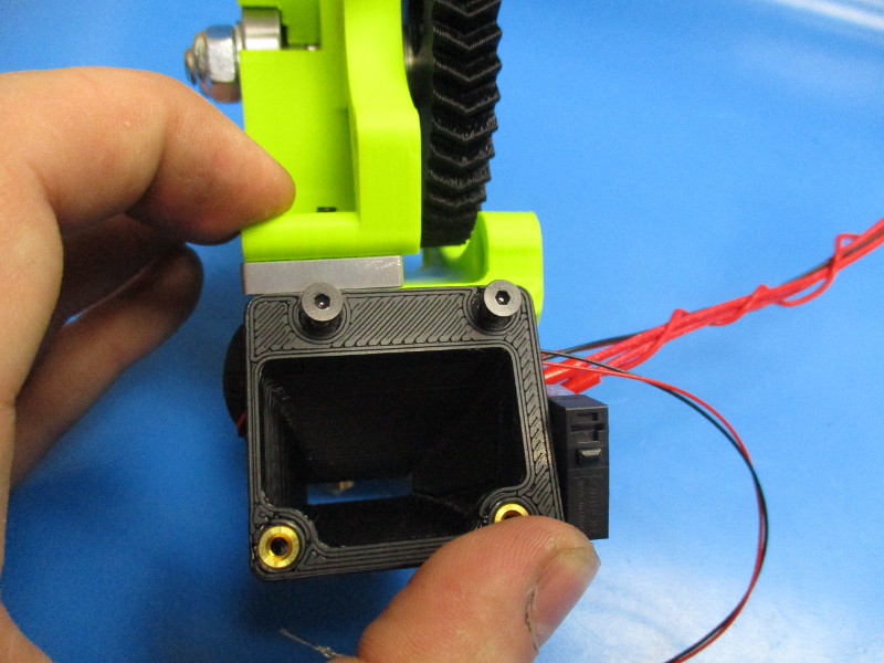
Orient the extruder fan mount so the small brass inserts are facing upward.
Install the switch onto the extruder fan mount. Torque the M2x10 screws to 2in*lbs.
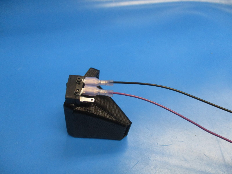
Attach the purple switch harness onto the middle prong connector.
Attach the black switch harness onto the top prong connector.


Gather parts
Tools needed:
Instructions:
Before installing the fan mount, the harnesses need to be move out of the way so they don't get pinched.
Align the countersunk holed in the extruder fan duct with the threaded inserts on the extruder body. Fasten the fan mount to the body using the M3x14 screws. Torque to 5in*lbs
Gather parts
2x- M3x12 SHCS (HD-BT0039)
1x- 40mm 24v fan harness (assembly)
Tools needed:
Instructions:
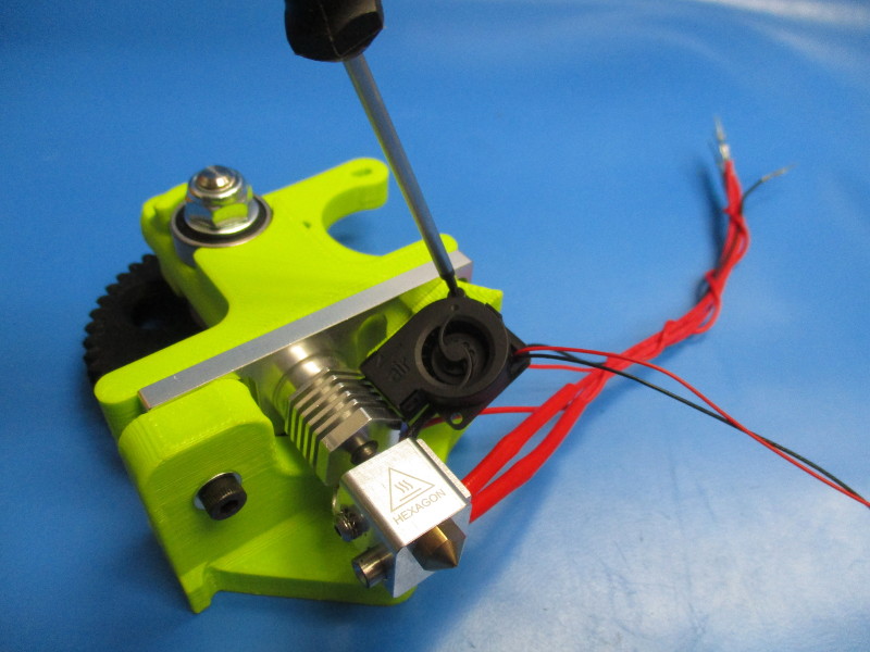
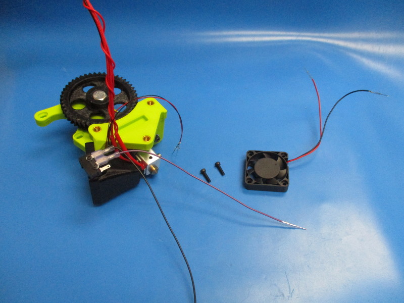
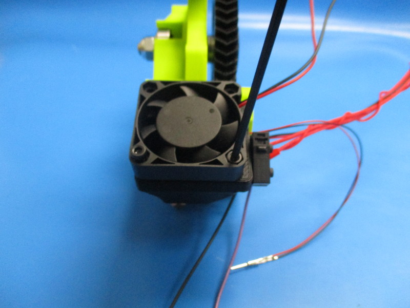
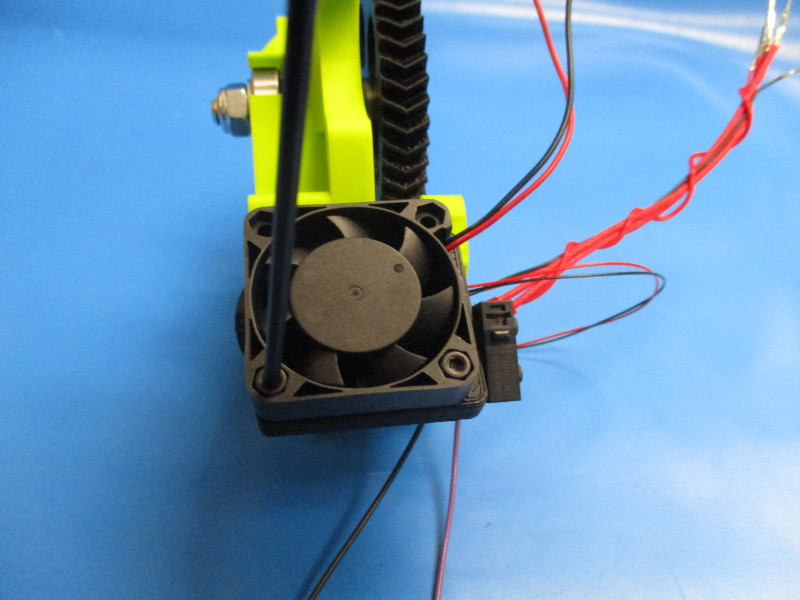
Align the 24v fan with the lower threaded inserts on the extruder fan mount. (note orientation of fan wires)
Fasten a M3x12 screw in the lower right and lower left holed of the fan. Torque to 5in*lbs

Gather parts
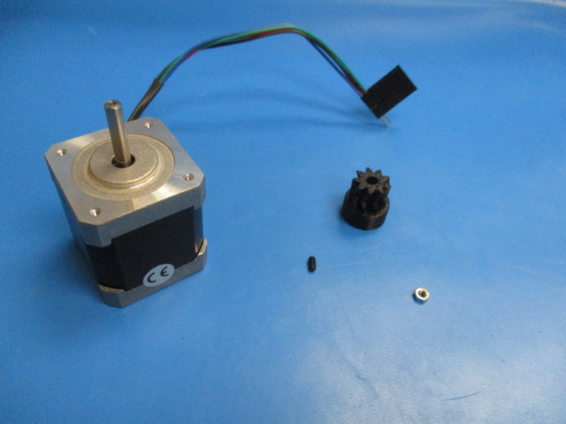
Small herringbone gear, black (PP-GP0062)
M3 nut (HD-NT0004)
Nema 17 stepper motor (EL-MT0001)
M3x4 set screw (HD-BT0012)
Tools needed:
Instructions:
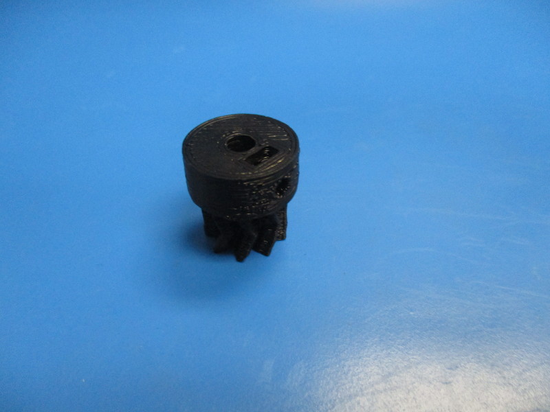
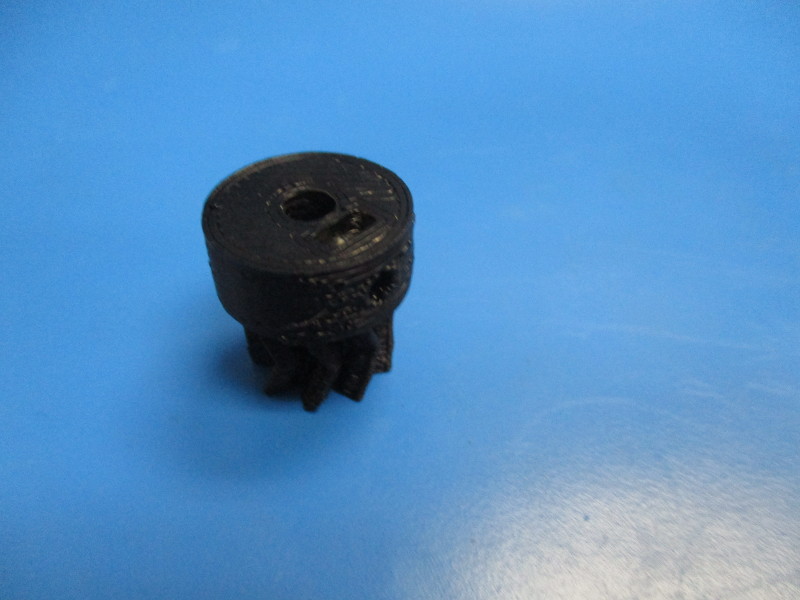
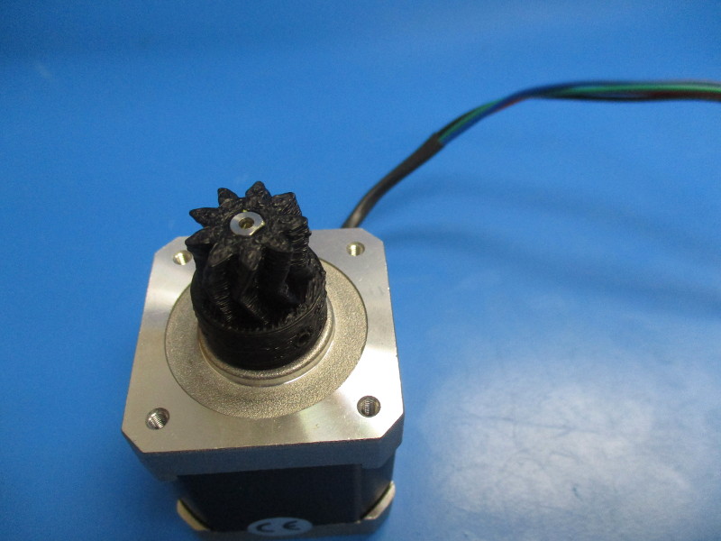
Set the small herringbone gear onto the flat face of the gear half so the nut slot is facing upwards. Insert the M3 nut into the nut slot. Use a driver to push it down into the slot to the nut hole and the hole on the side of the gear line up. Insert the M3x4 set screw into the hole aligned with the nut. Fasten the set screw until flush with the gear.
Install the small herringbone gear onto the Nema 17 stepper motor. Align the set screw with the flat section of the motor shaft. Finger tighten the set screw.

Attaching the motor assembly to the extruder assembly
Gather parts
3x- M3x12 SHCS (HD-BT0039)
3x- M3 washer (HD-WA0001)
Tools needed:
Instructions:
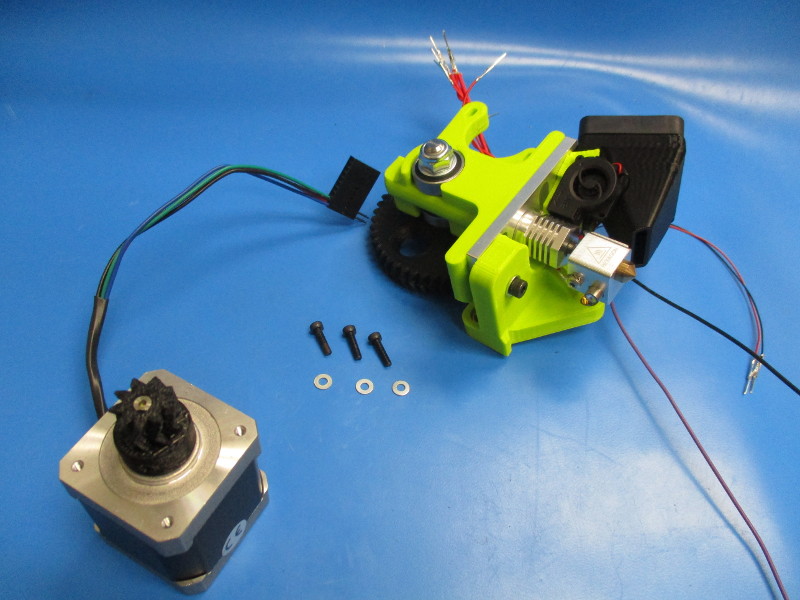
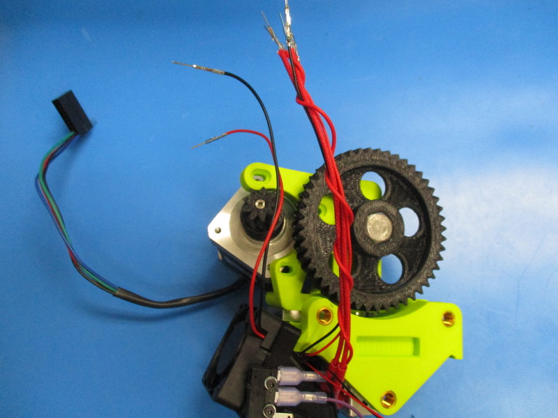
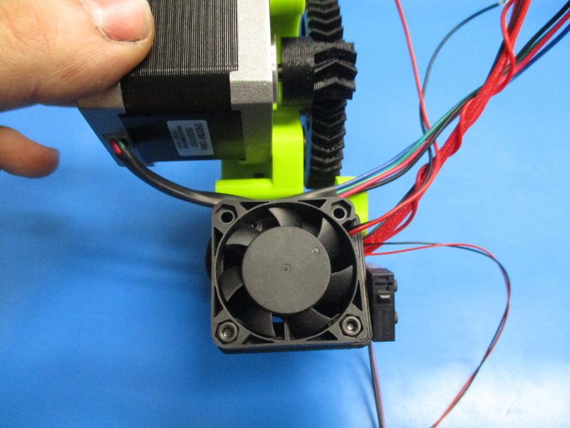
Mount the motor to the body (note the orientation of the motor and harness)
Place the M3x12 SHCS with black oxide in the three holes that line up with the tapped holes in the motor.
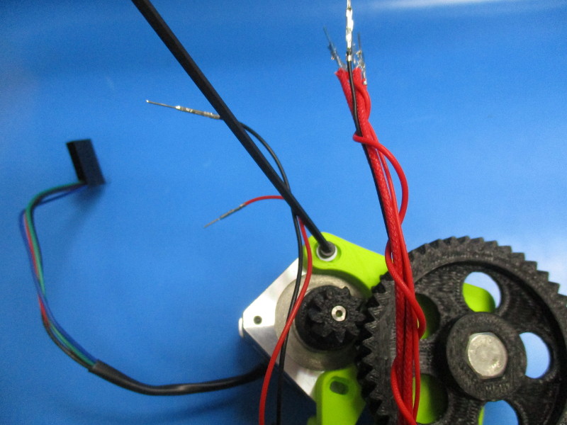
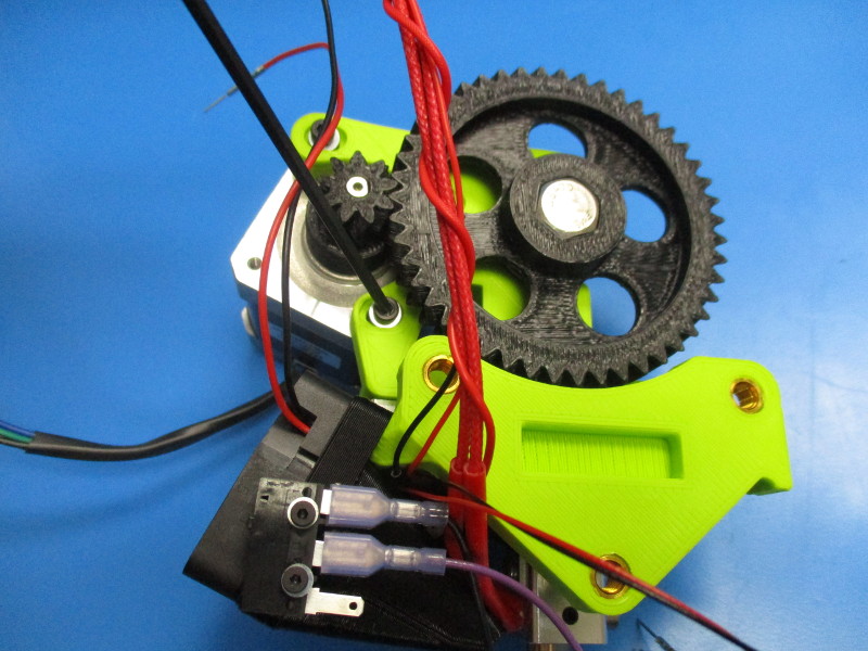
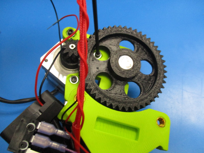
Note: the large gear and the small gear need to be mated together in a way that there is easy rotation but won't have any free movement known as “slap” between the gear teeth.
1) To test for proper alignment of gears - tighten your screws down to 3 in/lbs, Hold the small gear firmly with your finger and thumb, and try to move the large gear back and forth to see if there is any small movement between the teeth of the gears.
2) Rotate the large gear ¼ turn and repeat this process multiple times to ensure alignment. If there is movement the small gear and large gear need to be moved closer to each other. To do this you need loosen the M3 screws ¼ turn counter-clockwise and push the motor closer to the body. Repeat until you have desired the results, tighten screws once the fit is correct.) Torque to 3in*lbs
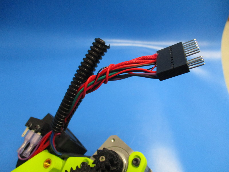
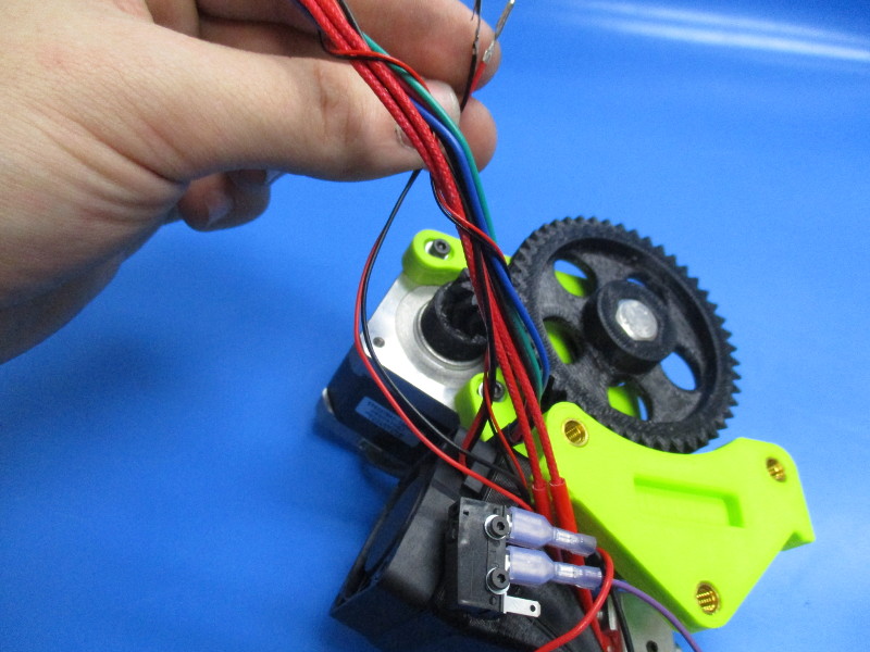
Run the motor harness on top of the 24v fan
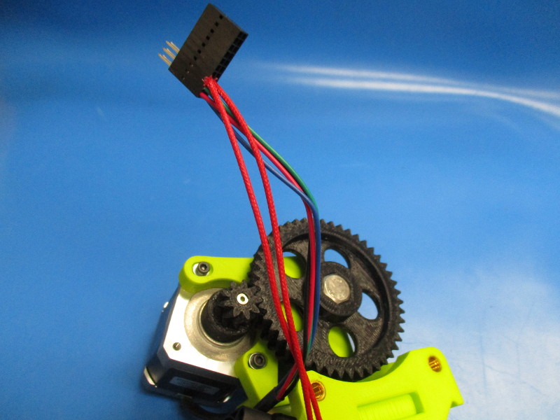
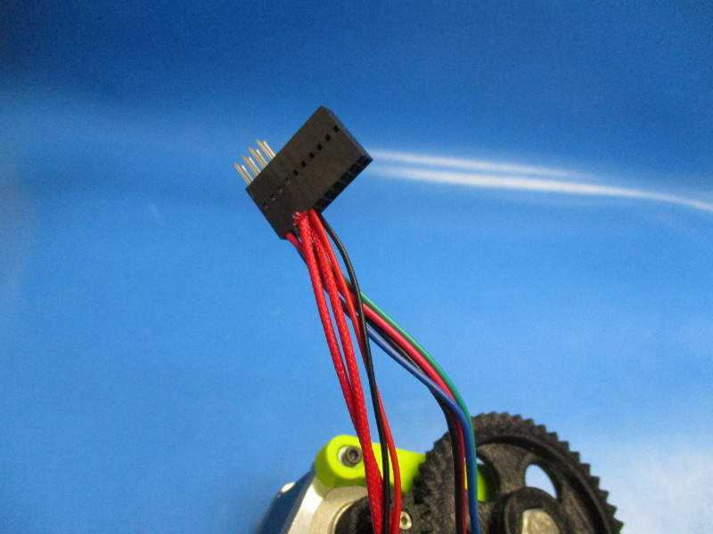
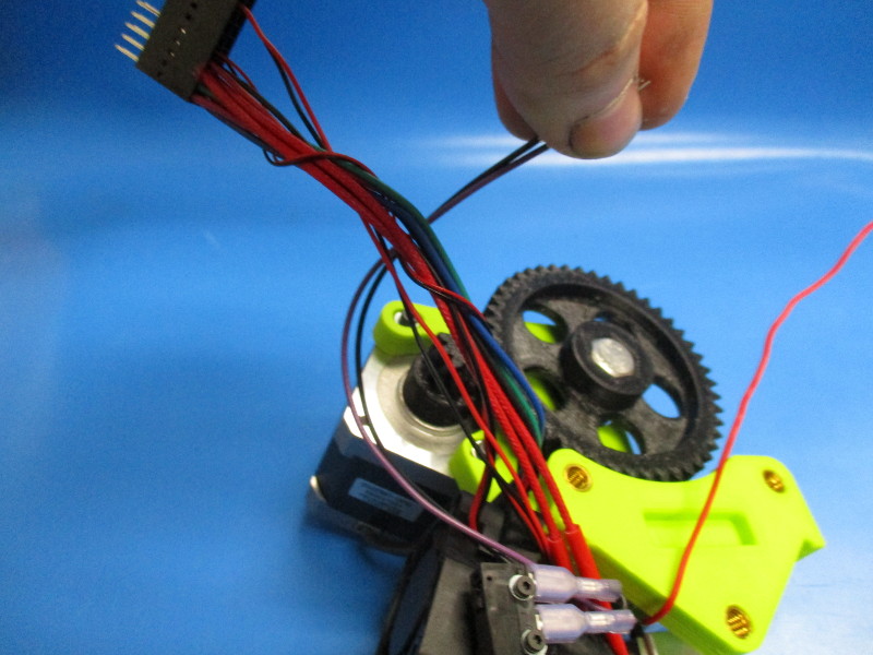
Most of the harnesses going to the 20 pin connector will need to twist around the motor switch harness.
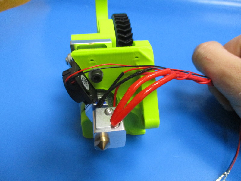
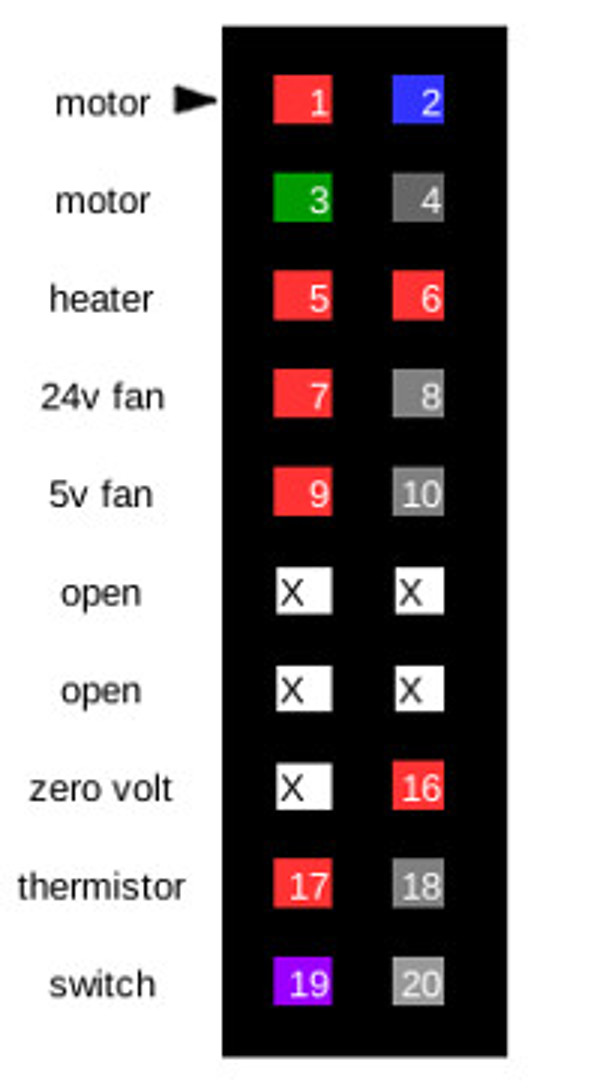
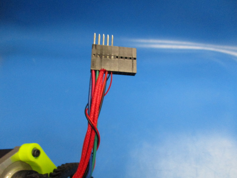
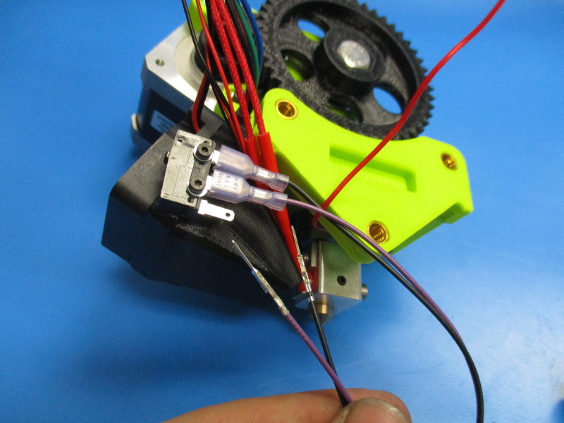
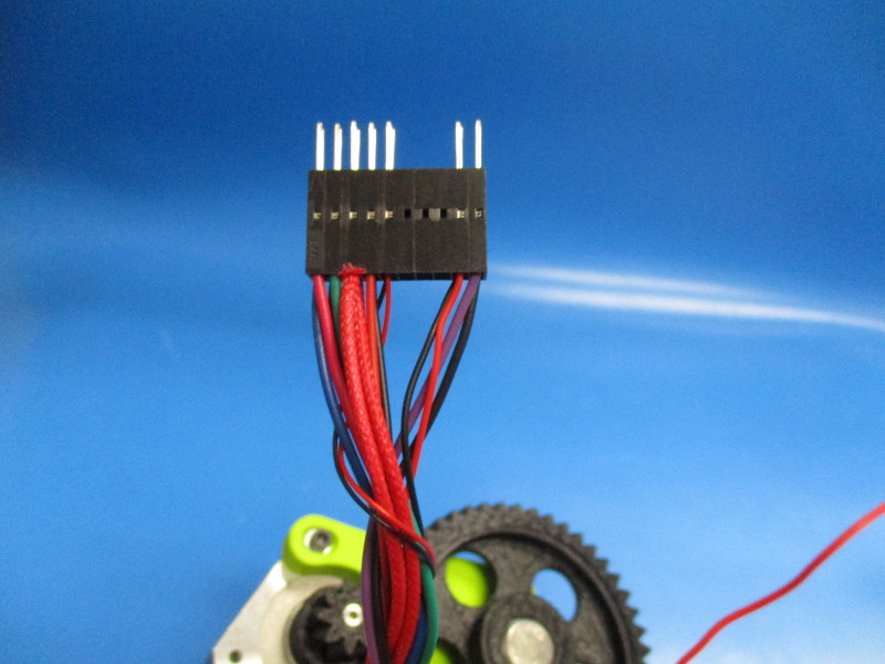
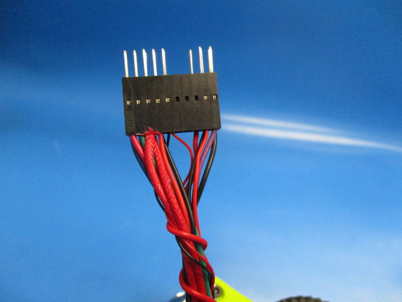
Start with connecting the heater cartridge harness. The heater cartridge harness will sit parallel with the motor switch harness, no twisting required (see image “ Heater cartridge connected”) Plug the heater cartridge pins into pin position 5 and pin position 6 (see image “Pin placement”)
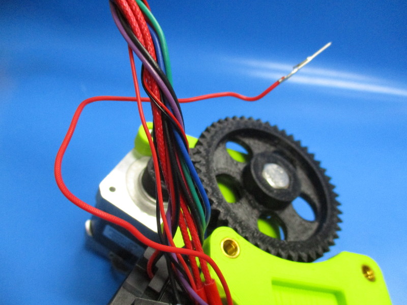
Connecting the 24v fan harness This harness will also run parallel with the motor switch harness (see image “24v fan connected”) Connect the 24v fan harness red wire in pin position 7 and the black wire in pin position 8 (see image “Pin placement”)
Connecting the micro blower harness This harness needs to be twisted around the motor switch harness, heater cartridge and 24v fan harness 3 times to reduce the length of the harness. (see image “twisting micro blower harness” and “Micro blower connected”) Connect micro blower red wire in pin position 9 and black wire in pin position 10 (see image “Pin placement”)
Connecting the thermistor harness This harness needs to be twisted 1 time around the previously connected harness. ( see image “twisting thermistor”) Connect the thermistor harness red wire in pin position 17 and black wire in pin position 18 (see image “Pin placement”)
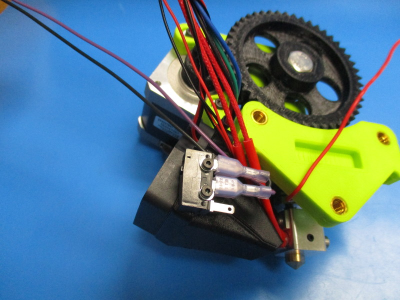
Connect the switch harness. Take the pin side of the harness and run it under the switch (see image “Feeding switch harness” and “switch harness loop”) Pull the harness until the loop closes (see image ”closing loop”) Connect the switch harness into purple wire in pin position 19 and black wire in pin position 20 (see image “Pin placement”)
Connecting the zero volt sense This harness needs to be twisted around the installed wire 4 times. ( see image “twisting zero volt harness”) Connect the zero volt harness into pin position 16 (see image “Pin placement”)


Gather parts
Cable tie (HD-MS0058)
70mm of 1/4in panduit (EL-MS0073)
Tools needed:
Instructions:
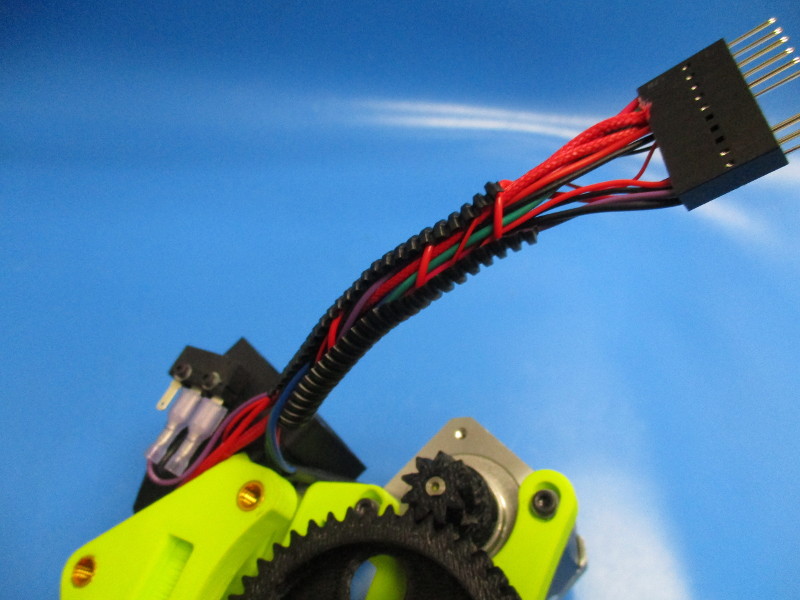
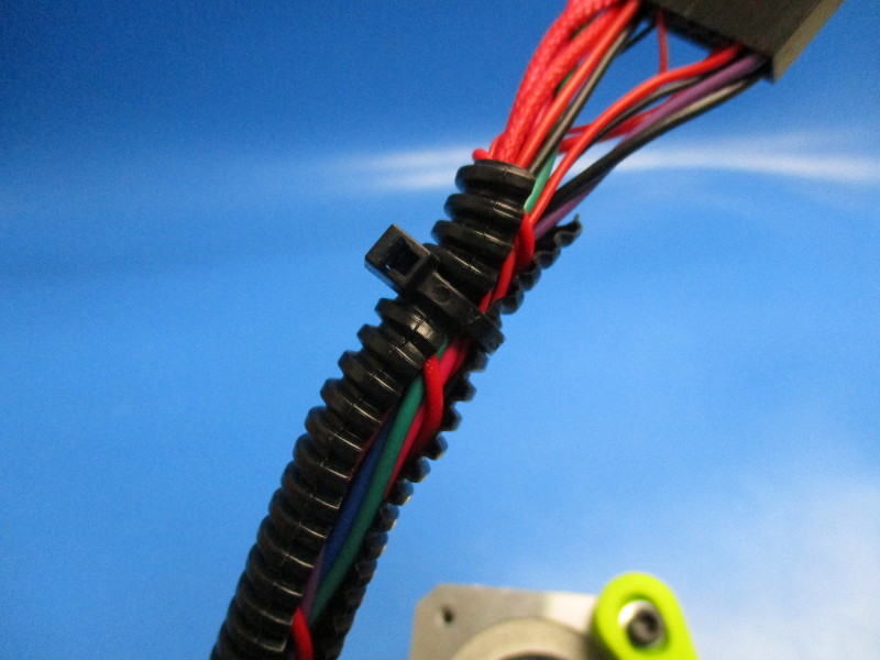
Slide the panduit onto the harnesses.
Cable tie the top about 10mm from the edge. Clip excess cable tie.