Open HardwareAssembly Instructions
Guides for installation and assembly of the LulzBot line of products made by FAME 3D LLC.
Guides for installation and assembly of the LulzBot line of products made by FAME 3D LLC.
Note:
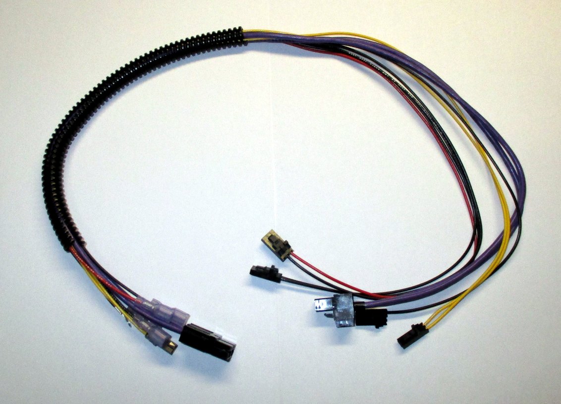
This replacement bed harness cable is compatible with LulzBot Mini 3D printers with a serial number range up to: KT-PR0035NA-07126 and KT-PR0035EU-6703.
WARNING:
At Aleph Objects, Inc. we respect your freedom to modify your LulzBot 3D printer. Any modifications or attempted repairs that cause damage are not covered under the Warranty.
Questions? Contact Technical Support by emailing Support@LulzBot.com, or by calling +1-970-377-1111.

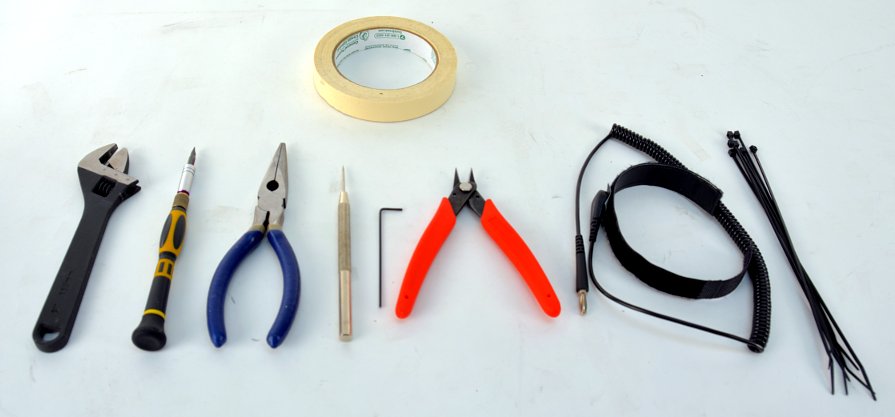
Recommended
3A
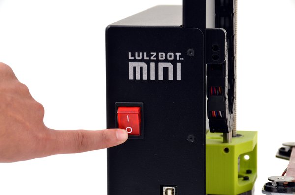
Remove filament if desired or place the filament reel off to the side. Turn off the 3D printer
3B
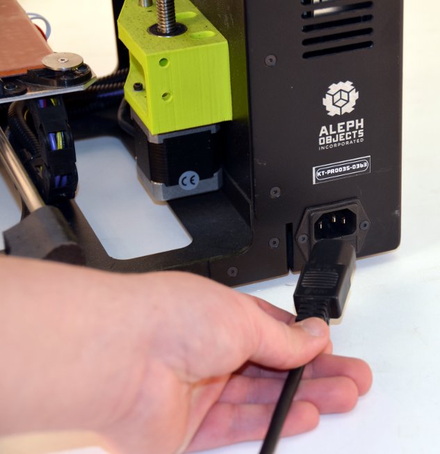
Unplug power cable
3C
Unplug USB cable

Ground yourself on a floor-touching metal object prior to touching the control board to avoid potential Electric Static Discharge (ESD) damage.
4A
Put on the anti-static bracelet if available.
4B
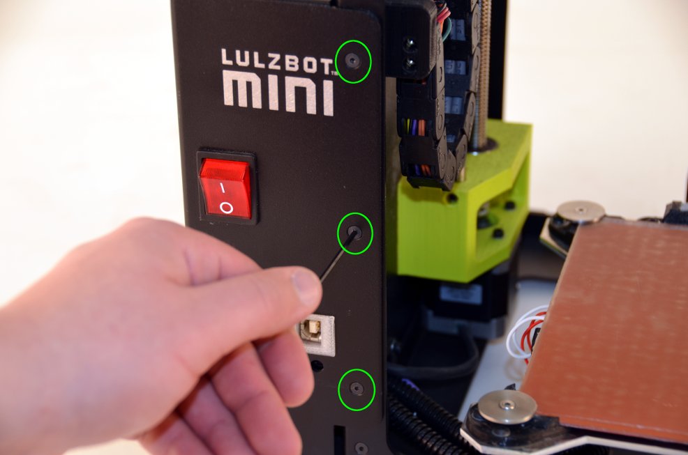
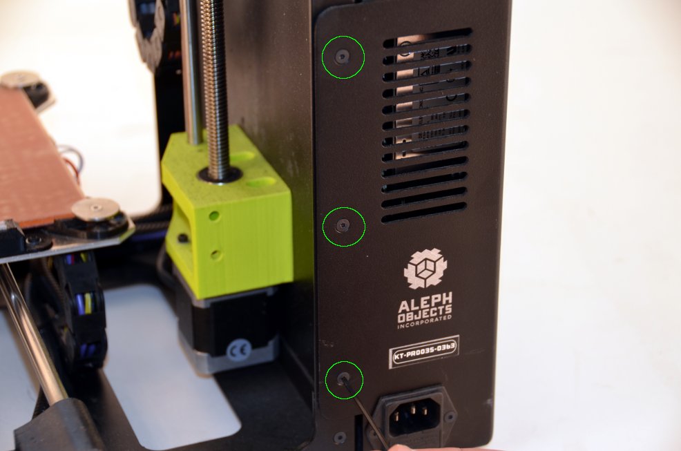
Use the 2 mm hex driver to remove the six screws securing the electronics enclosure to the 3D printer frame. Place the three front and three rear enclosure screws in a secure location.
4C
Carefully pull the electronics enclosure away from the printer frame.
Note: The electronics enclosure fan is still connected.
Note: The red wire is positive and marked with +. The black wire is negative and marked with -
4D
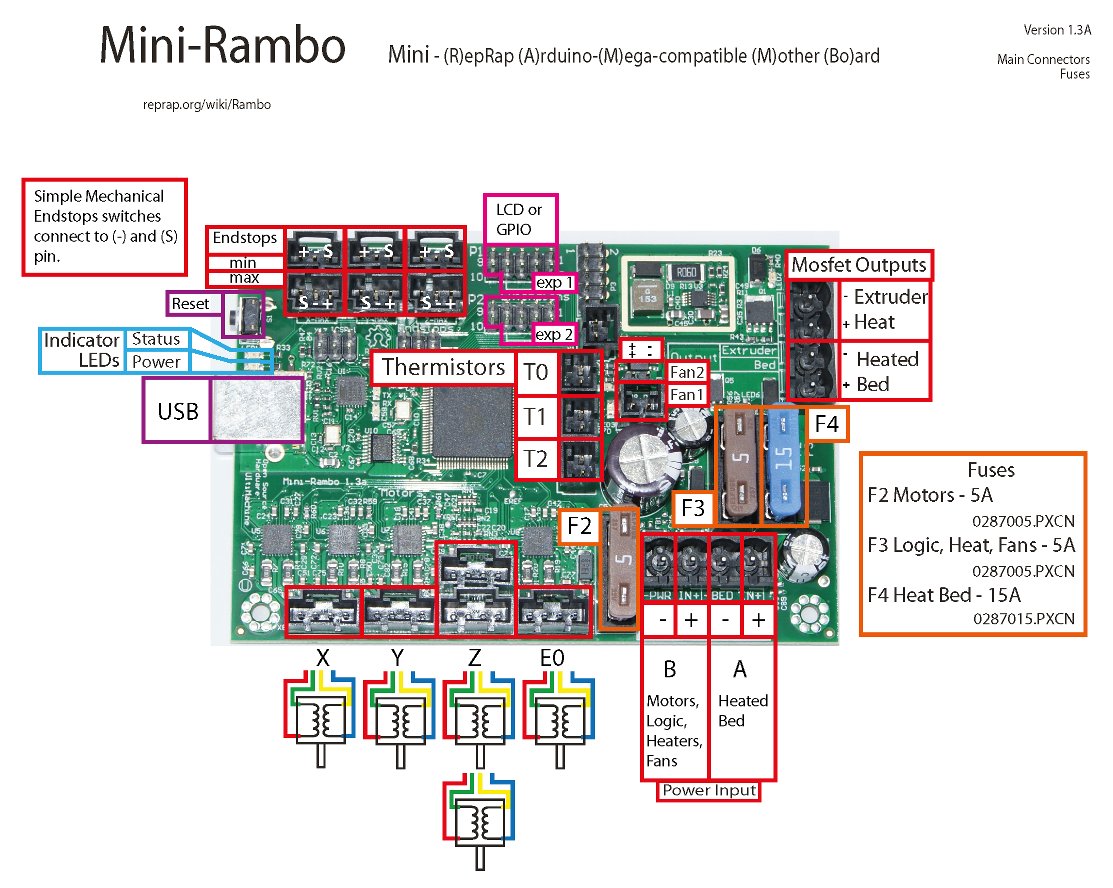
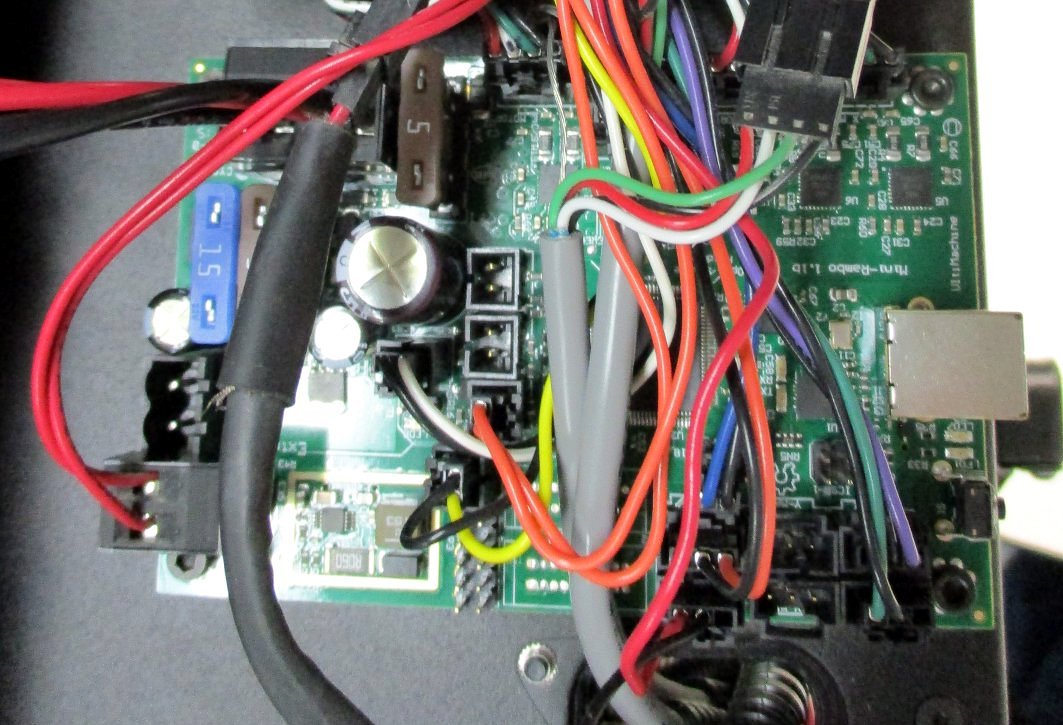
Locate the main input power connector. This 4 wire connector will have four wires consisting of two red and black wire pairs and can be found on the upper portion of the Mini-Rambo, towards the rear of the 3D printer.
5E
Unplug the main power connector by lifting straight out from the Mini-Rambo. Do not twist or remove at an angle.
6F
Place the 3D printer on the side with the Mini-Rambo facing up and with the underside of the Y-axis visible.


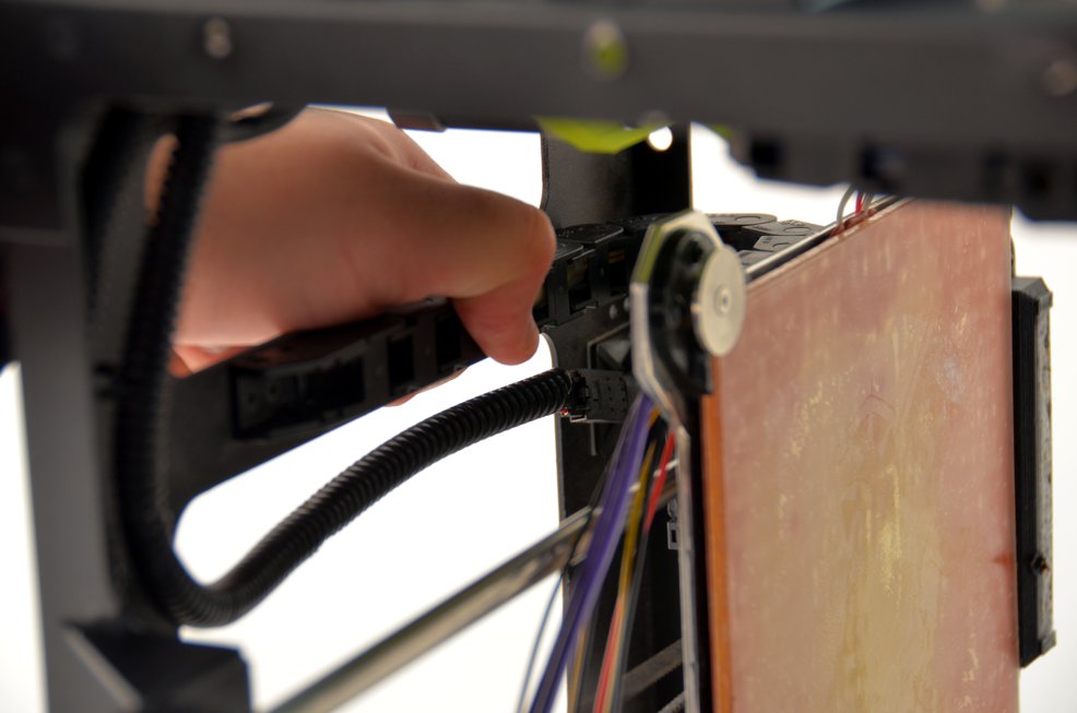
Note: Carefully unwrap the following wires only to help minimize loose wiring.
5A
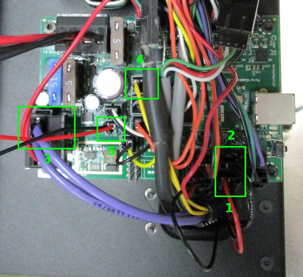
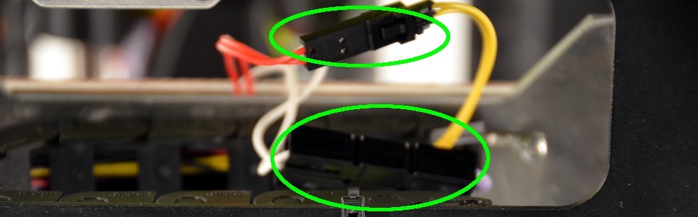
Locate the Y-axis Min end stop connector. This red and black wire pair has a three-wire connector and is secured with a locking tab. Press in on the locking tab and disconnect the Y-axis Min end stop wiring. Image Labeled 1
5B
The Y-axis Max end stop is next to the previous connector. This double black wire pair has a three-wire connector and is secured with a locking tab. Press in on the locking tab and disconnect the Y-axis Max end stop wiring. Image Labeled 2
5C
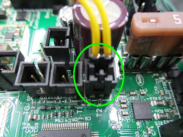
Locate the print bed thermistor connector. Identify the two pin yellow wire pair with locking tab. Press the locking tab in and disconnect by print bed thermistor wiring. Image Labeled 3
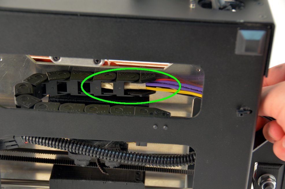
5D
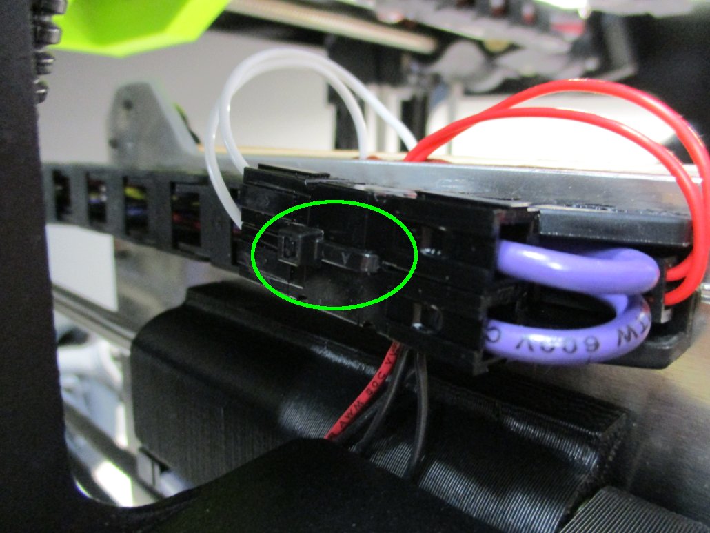
Locate the print bed heater connector. Identify the large-diameter purple wire pair. Disconnect the print bed heater wiring by lifting straight up and away from the Mini-Rambo. Image Labeled 4
5E
Locate the case fan connector. Unplug the red and black wire pair. Image Labeled 5
5F
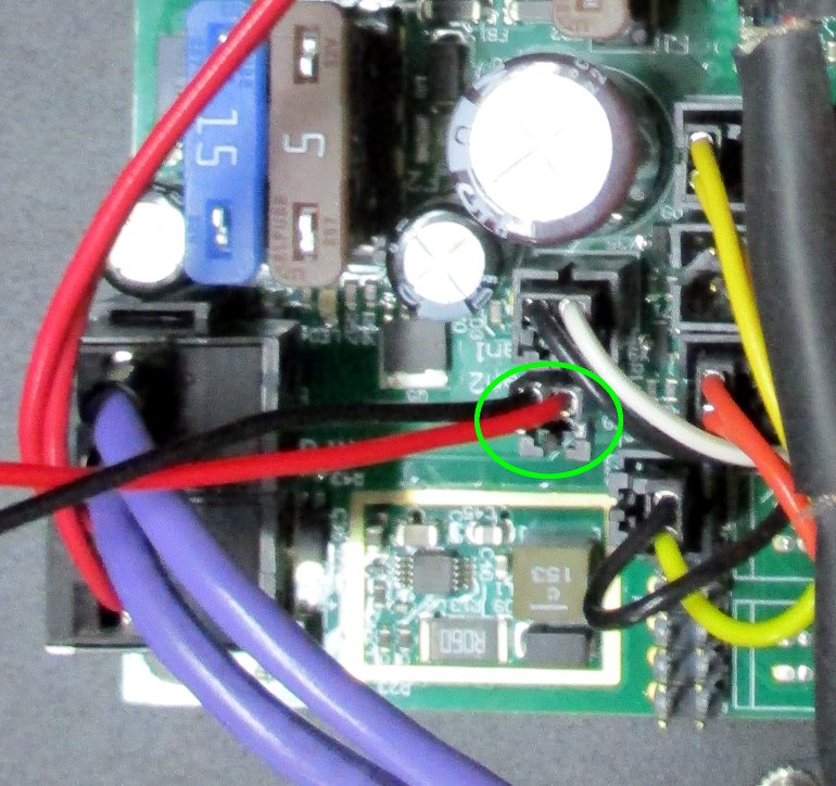
Locate the Z-axis ground connector. Unplug the red and black wire pair by pressing in the locking tab and disconnect the Z-axis ground wiring.


Three connectors on the the existing wiring harness will need to be removed to allow wiring harness replacement.
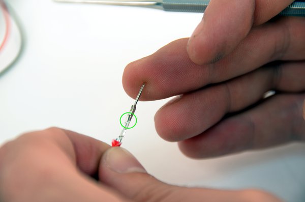
Note: The dental pick is sharp.
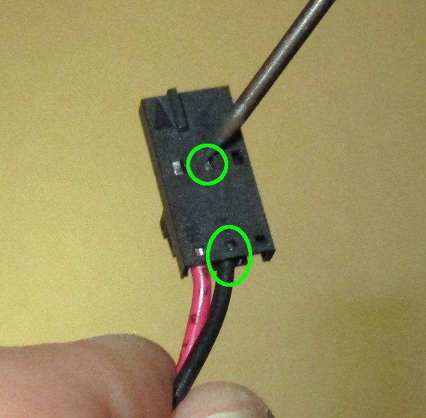
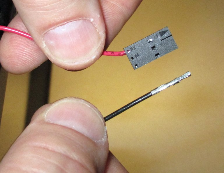
6A
Remove the pins from the three pin Y-axis Min end stop connector with the red and black wire pair. Use the dental pick or other sharp pointed instrument to gently push down on the locking catch for each metal pin through the small square opening closest to the end.
Note: Only use the small square opening nearest the wiring if the locking tab catches it. Slide out the two pins.
6B
Remove the pins from the three pin Y-axis Max end stop connector with the black and black wire pair. Gently push down on the locking tab for the two pins and slide out the two pins.
6C
Remove the pins from the two pin heated bed thermistor connector with the yellow and yellow wire pair. Gently push down on the locking tab for the two pins and slide out the two pins.
6D
Remove only the black wire pin from the two pin Z-axis Min end stop connector with the red and black wire pair. The connector will not need to be pulled through the cable chain.
6E
Use the 2 mm flat screwdriver to free the large purple and purple wire pair from the two pin heated bed power screw terminal connector.


Note: Take care not to damage the crimp terminals.
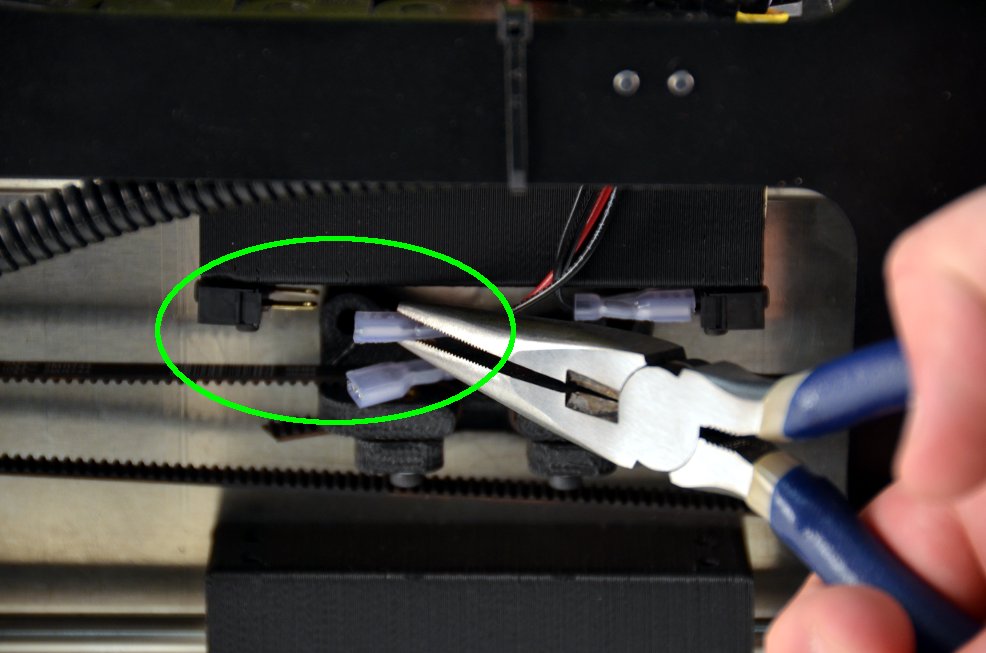
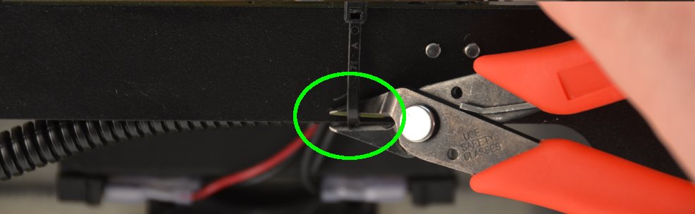
7A
Gently disconnect Y-axis Min end stop wire by pulling away from the switch using needle nose pliers.
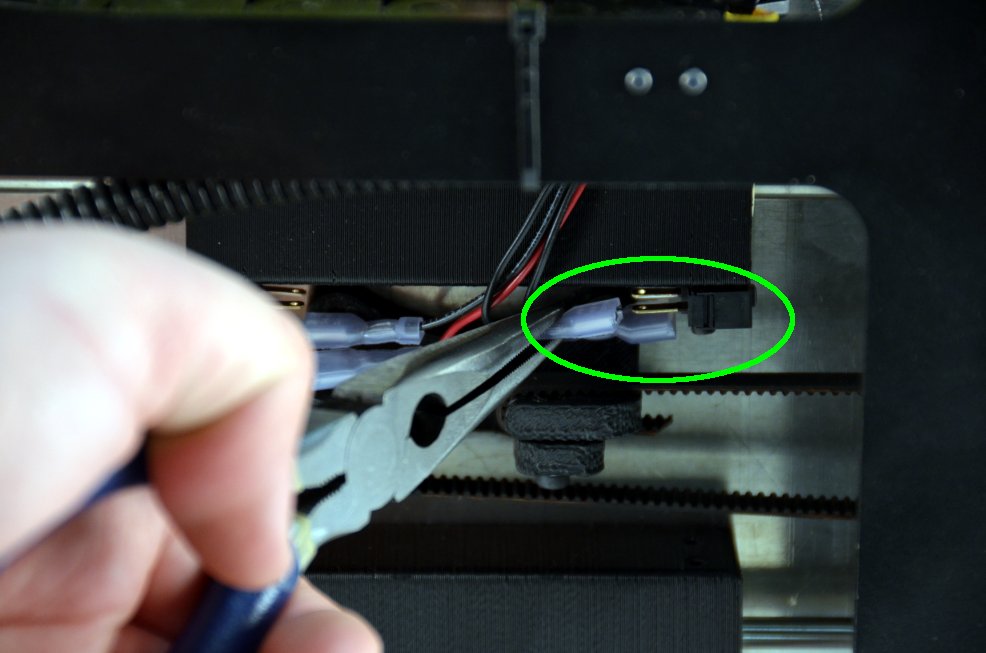
7B
Gently disconnect Y-axis Max end stop wire by pulling away from the switch using needle nose pliers.
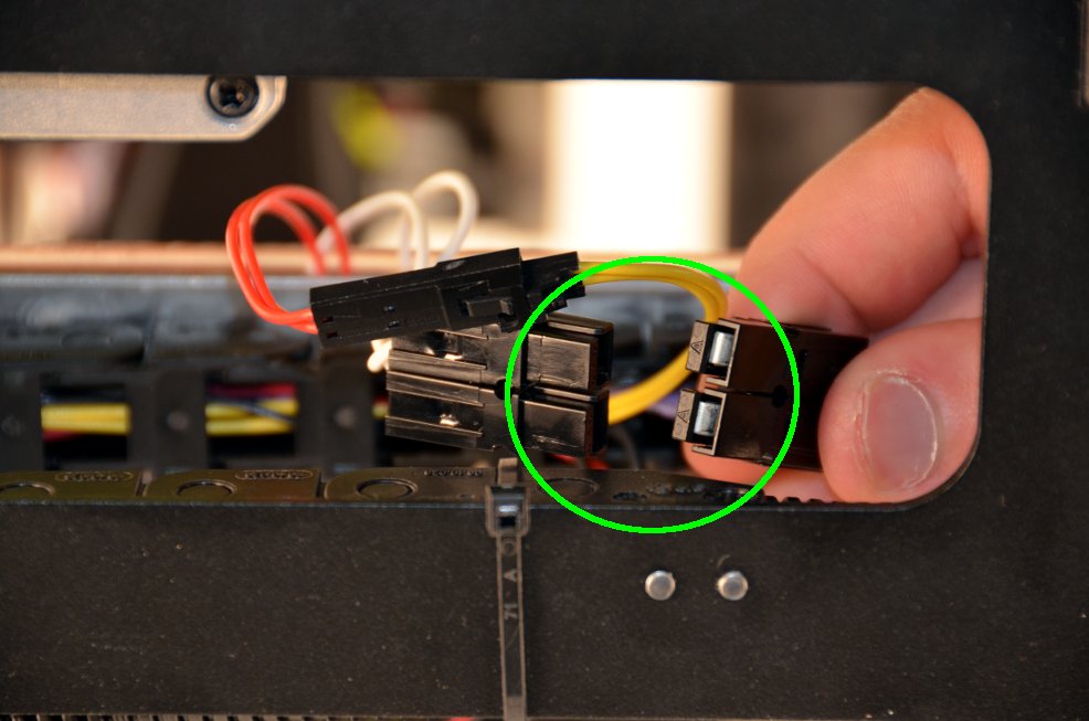
7C
Disconnect the smaller two wire pair heated bed thermistor connector while pressing on the locking tab.
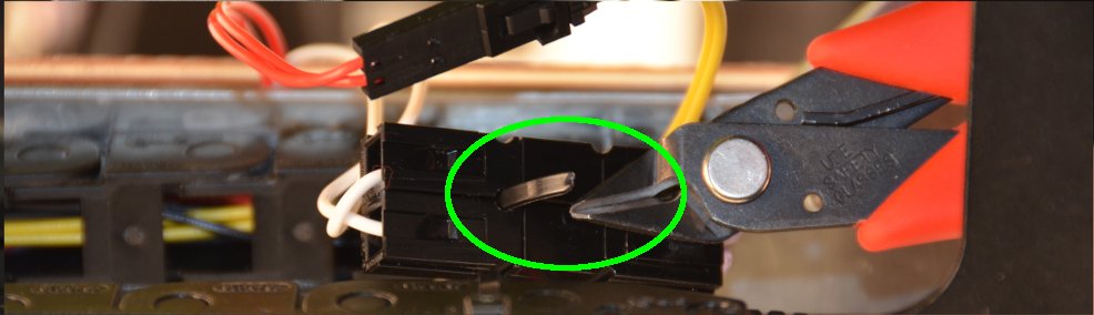
7D
Use the flush cutters or scissors to cut the small zip tie securing the larger two wire pair heated bed power connector. Cut the small zip tie securing the cable chain. Throw away the zip ties.
7E
Disconnect the larger two wire pair heated bed power connector by pulling them apart.
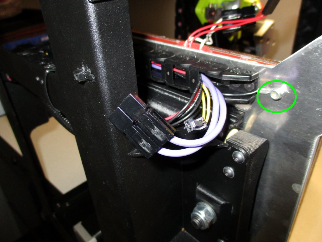
7F
Unscrew the Z-axis ground wire, using either a hex driver, wrench, or needle nose pliers. Place the screw or nut in a secure location.

8A
Move the print surface all the way to the back of the Y-axis.
8B
While holding the print surface in place with one hand, grab and gently pull the wiring harness out of the cable chain. Do not jerk or force the wires out.


Tips:
9A
Remove the pins from the three pin Y-axis Min end stop connector with the red and black wire pair. Use the dental pick or other sharp pointed instrument to gently push down on the locking catch for each metal pin through the small square opening closest to the end.
Note: Only use the small square opening nearest the wiring if the locking tab catches it. Slide out the two pins.
9B
Remove the pins from the three pin Y-axis Max end stop connector with the black and black wire pair. Gently push down on the locking tab for the two pins and slide out the two pins.
9C
Remove the pins from the two pin heated bed thermistor connector with the yellow and yellow wire pair. Gently push down on the locking tab for the two pins and slide out the two pins.
9D
Remove only the black wire pin from the two pin Z-axis Min end stop connector with the red and black wire pair. The connector will not need to be pulled through the cable chain.
9E
Use the 2 mm flat screwdriver to free the large purple and purple wire pair from the two pin heated bed power screw terminal connector.
10A
Bind the wire pairs and pins together using as little tape as possible.
10B
Remove the split round wire wrap from the new replacement bed cable harness.
10C
Move the print surface all the way to the front of the Y-axis.
10D
Carefully slide the wire bundle, tape end first, through the cable chain under the print bed assembly. Stop before the cable chain bend.
Note: this step can be done with all of the wires in a single bundle or pair by pair. If you are unsuccessful with pushing the wires through all at once, try doing them one pair of wires at a time.

11A
Move the print surface all the way to the back of the Y-axis.
11B
Continue gently guiding the wire bundle through the cable chain. Use a finger to block gaps in the cable chain and to help allow the bundle to pass through.
11C
Gently pull the wire bundle through, leaving room at the bed end of the wiring bundle, similar to the attached picture.
11D
Route the taped wire bundle end through the wire pass-through in the frame.
11E
Remove the tape covering the pins once the bundle is through
11F
Place the split round wire wrap back on the new bed cable harness with the end of the round wire wrap inside of the pass-through.

Tips:
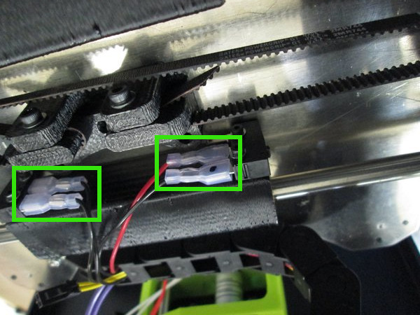
12A
Connect the red and black wiring pair to the Y-axis Min end stop micro-switch found at the rear of the print bed assembly, closest to the cable chain curve.
12B
Connect the black and black wiring pair to the Y-axis Max end stop micro-switch found at the front of the print bed assembly, closest to the cable chain end.
12C
Plug in the small two wire connector to the heated bed thermistor connector.
12D
Plug in the larger two wire connector to the heated bed power connector. Use a small zip tie to secure the connector.
12E
Attach the Z-axis ground wire to the underside of the print bed assembly, remembering to use the star lock washer. Tighten just past finger tight using the 2 mm hex driver, needle nose pliers, or wrench.

Tips:
13A
Insert the pins with the red and black wire pair into the three pin Y-axis Min end stop connector. Slide the pins in until the pin catch is visible in the small square opening closest to the connector end.
13B
Insert the pins with the black and black wire pair into the three pin Y-axis Max end stop connector . Slide the pins in until the pin locks in place.
13C
Insert the pins with the yellow and yellow wire pair into the two pin heated bed thermistor connector. Slide the pins in until the pin locks in place.
13D
Insert the sole black wire pin into the two pin Z-axis Min end stop connector. Slide the pin in until locked in place.
13E
Insert the large purple and purple wire pair into the two pin heated bed power screw terminal connector. Use the 2 mm flat screwdriver to attach the connector to the pins.

14A
Plug in the red and black wire three pin connector into the Y-axis Min end stop connector labeled Y-min.
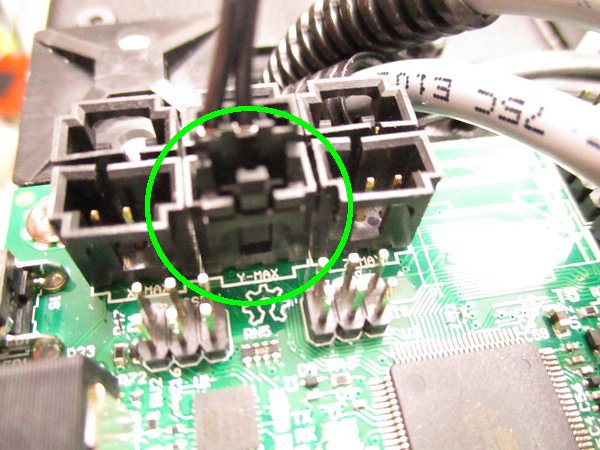
14B
Plug in the black and black wire three pin connector into the Y-axis Max end stop connector labeled Y-max.
14C
Plug in the yellow and yellow two wire connector into the bed thermistor connector labeled T2.
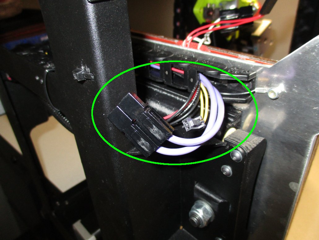
14D
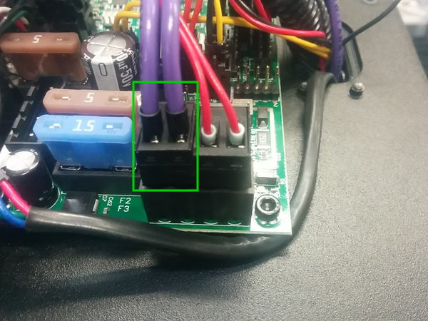
Plug in the purple and purple two wire screw terminal connector into the bed heater connector matching the orientation shown in the attached picture.
14E
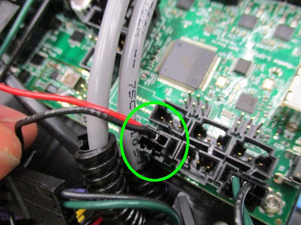
Plug in the red and black wire three pin connector into the Z-axis ground connector labeled Z-min. The Z-axis ground connector has the same pin colors as Y-min (see step 14A) so it is very easy to mistake these two. One way to tell is that the Z-axis ground connector has one wire going to the bed, and another wire going up to the toolhead, while the Y-min connector has both wires going to the bed.
14F
Plug in the electronics fan cable matching the polarity and orientation shown in the attached picture. The black wire should be on the same side as the heated bed power connector with the large purple wire pair.
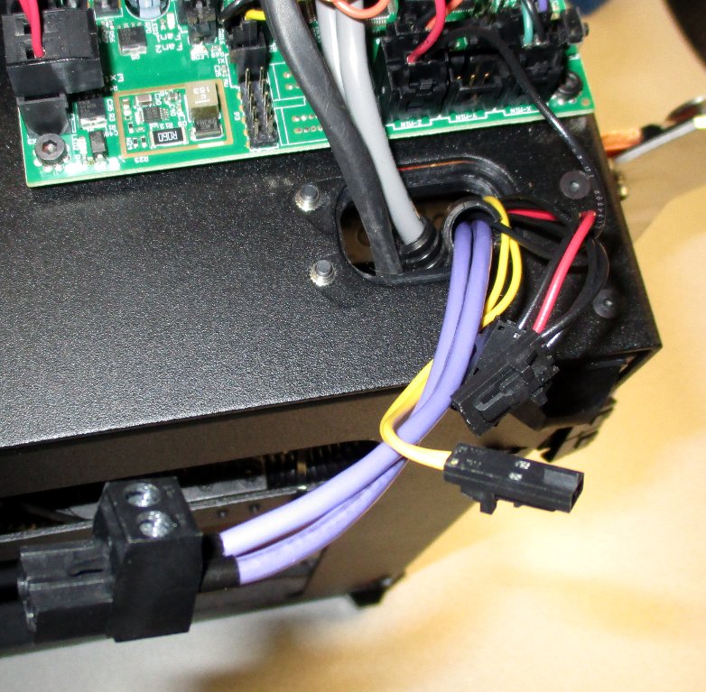
14G
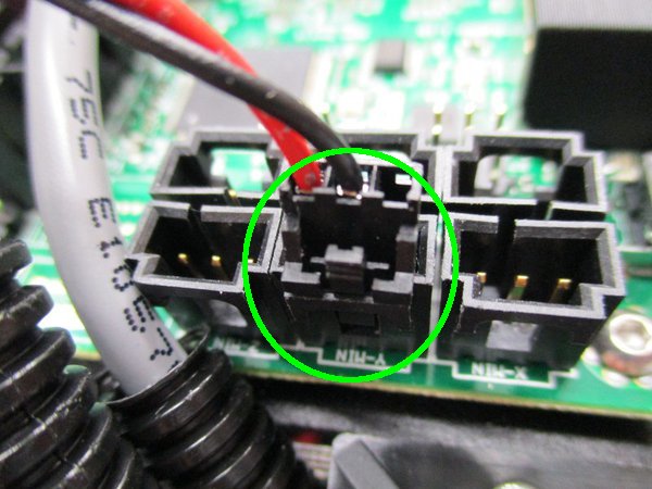
Plug in the four pin power connector with the red and black wire pair matching the polarity and orientation shown in the attached picture.


15A
Slide the electronics enclosure back in place, taking care to keep all wiring away from the case fan blades.
15B
Use the 2 mm hex key or driver to install the six screws securing the electronics enclosure to the 3D printer frame-- three in the front and three in the rear of the electronics enclosure.


16A
Use a small zip tie to secure the wiring harness to the bottom frame of the printer.
16B
Use a small zip tie to secure the heated bed power connector.
Verify the functionality of the printer prior to your first test print.
Prior to moving any axis:
Prior to heating the hot end or heated bed:
Start a test print and carefully observe the auto bed leveling sequence.
During the auto bed leveling sequence the nozzle should lightly touch down on each metal corner of the bed.
If you encounter issues please contact Technical Support by emailing Support@LulzBot.com, or by calling +1-970-377-1111.
