Open HardwareAssembly Instructions
Guides for installation and assembly of the LulzBot line of products made by FAME 3D LLC.
Guides for installation and assembly of the LulzBot line of products made by FAME 3D LLC.
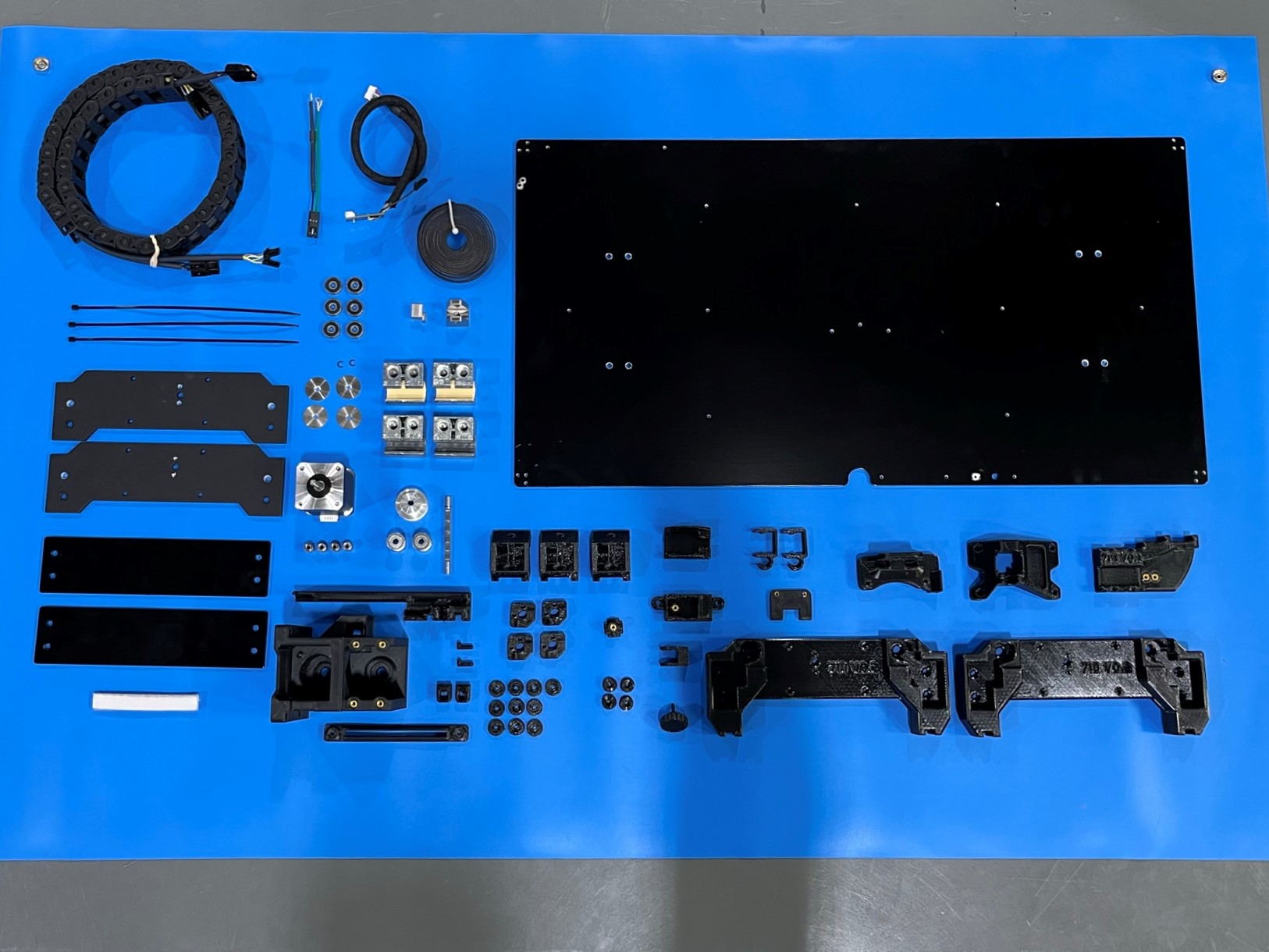
1x- [AS-CB0175] Y Motor Extension, Long Bed
1x- [AS-CB0192] Bed Harness, Long Bed
1x- [AS-HB0019] Modular Long Bed Heater
1x- [EL-HR0146] TAZ Pro/WE, Bed Extension Harness
1x- [EL-MT0068] NEMA 17 Stepper Motor, LDO
1x- [HD-BL0037] Single Sided Open Loop Belt 2310mm
1x- [HD-BL0041] GT2 Rubber Timing Belt, Closed Loop
2x- [HD-EX0109] Drylin with Pillow Blox Die Cast
2x- [HD-EX0110] T-Slot Aluminum Frame TPW, Extrusion
2x- [HD-EX0111] WJUM-01-16-LL Drylin W Carriage
2x- [HD-MS0070] GT2 Timing Pulley 20T 5mm Bore 10mm Width
4x- [HD-MS0287] SST Unthreaded Spacer 8mm
1x- [HD-MS0300] 2GT Timing Pulley 40T 5mm Bore 10mm Width
6x- [HD-MS0411] Premium Two Side Rubber Sealed Bearing
1x- [HD-MS0531] Scotch-Brite 98, Light Cleaning Pad
2x- [HD-RD0084] Drylin W Single Rail 16mm DIA 1180mm
1x- [HD-RD0089] 5mm x 200mm Rotary Shaft, 316 SS
2x- [PP-FP0226] Long Bed Y End Plate
2x- [PP-FP0227] Long Bed Bottom Support Brace
4x- [PP-GP0238] Flexy Bed Foot, TAZ6/Pro/WE
1x- [PP-GP0370] Y Belt Clamp, Pro/WE
1x- [PP-GP0381] Wiper Mount, Pro/WE
4x- [PP-GP0396] Bed Corner, Pro/WE
1x- [PP-GP0425] Y Chain Pivot, Pro/WE
10x- [PP-GP0446] Heater Bed Stand Off, Pro/WE
2x- [PP-GP0532] Belt Clamp, TAZ SideKick
1x- [PP-GP0713] Long Bed Y Cable Cover
1x- [PP-GP0714] Long Bed Y Chain to Bed
1x- [PP-GP0716] 2-1 Y Motor Mount, Long Bed
1x- [PP-GP0717] 2-1 Y Idler Housing, Long Bed
2x- [PP-GP0718] Combined Y End, Long Bed
1x- [PP-GP0719] 2-1 Y Belt Mount, Long Bed
1x- [PP-GP0721] 2-1 Y Motor Mount Bearing Cap
4x- [PP-GP0722] Chassis to Bed, Long Bed
1x- [PP-GP0723] Tension Block, Long Bed
1x- [PP-GP0724] Tension Knob, Long Bed
1x- [PP-GP0727] Harness Extender Housing, Cover
1x- [PP-GP0728] Harness Extender Housing, Base
2x- [PP-GP0729] 1 Bundle Cable Clip, Long Bed
4x- [PP-MP0082] Bed Leveling Washer, SST
1x- [PP-MP0225] YZ Idler, Pro/WE
1x- [PP-MP0227] XY Calibration Cube, Pro/WE
1x- [PP-MP0230] Long Bed Plate, 330 x 660 mm
11x- [HD-BT0039] M3x12 SHCS, Black-Oxide
4x- [HD-BT0049] M5x14 SHCS, Black-Oxide
10x- [HD-BT0073] M5x10 BHCS, Black-Oxide
4x- [HD-BT0082] M3x16 FHCS, SST
3x- [HD-BT0104] M3x8 BHCS, SST
4x- [HD-BT0128] M3x6 FHCS, Black-Oxide
4x- [HD-BT0137] M3x8 BHCS, Black-Oxide
10x- [HD-BT0140] M3x6 BHCS, Black-Oxide
13x- [HD-BT0148] M3x10 BHCS, Black-Oxide
2x- [HD-BT0151] M5x20 SHCS, Black-Oxide
2x- [HD-BT0157] M3x8 SHCS, Black-Oxide
10x- [HD-BT0158] M5x12 BHCS, Black-Oxide
10x- [HD-BT0171] M3x20 BHCS, Black-Oxide
1x- [HD-BT0175] M5x16 SHCS, Black-Oxide w/ Thread-Lock
2x- [HD-BT0256] M3x16 BHCS, Black-Oxide
8x- [HD-BT0272] M5x20 BHCS, Black-Oxide
8x- [HD-BT0277] M6x25 BHCS, Black-Oxide
2x- [HD-BT0283] M3x16 Flat-Tip Set Screw, Alloy Steel
11x- [HD-NT0001] M3 Nut
23x- [HD-NT0053] M5 T-Slot Nut
2x- [HD-WA0014] Retaining Ring 5mm
1x- [HD-WA0035] M3 Lock Washer
43x- [HD-WA0038] M3 Washer
43x- [HD-WA0040] M5 Washer
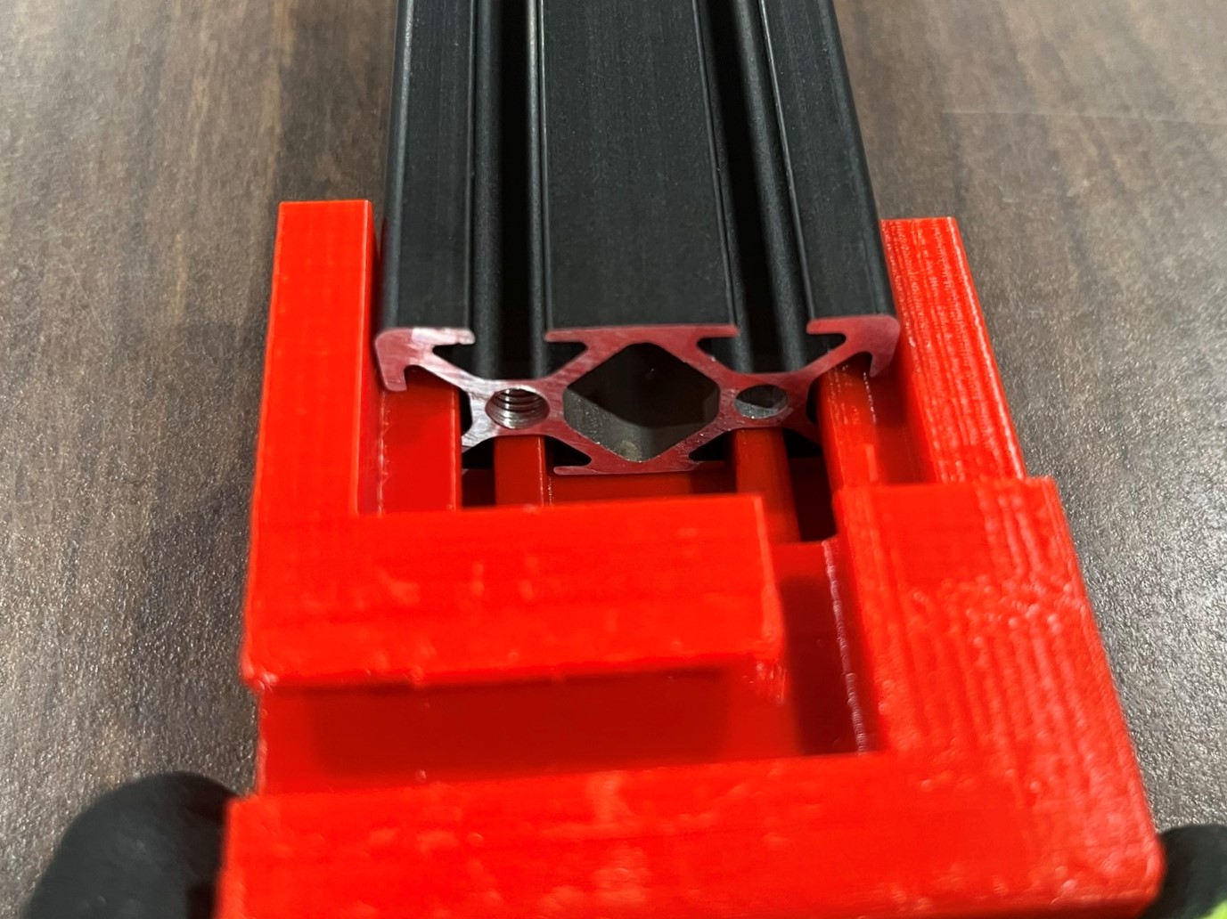
Before starting make sure the T-slot extrusions [HD-EX0110] have both sides tapped and that the Drylin W rails [HD-RD0084] have 5 holes drilled through them.
Take 1x T-slot extrusion and slide the T-slot Jig into one end of the extrusion.
Then align the T-slot spacer jig with the extrusion about 2 feet away. This is to support the rail to reduce friction
Preload the T-slot jig with T-slot nuts [HD-NT0053] making sure the flat side is on the top.
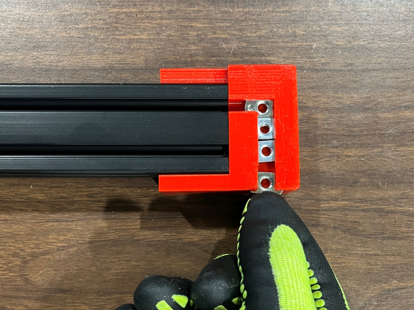
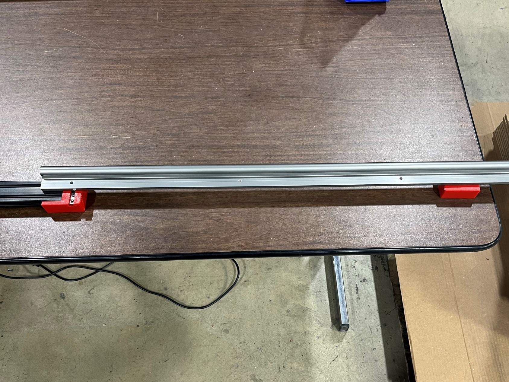
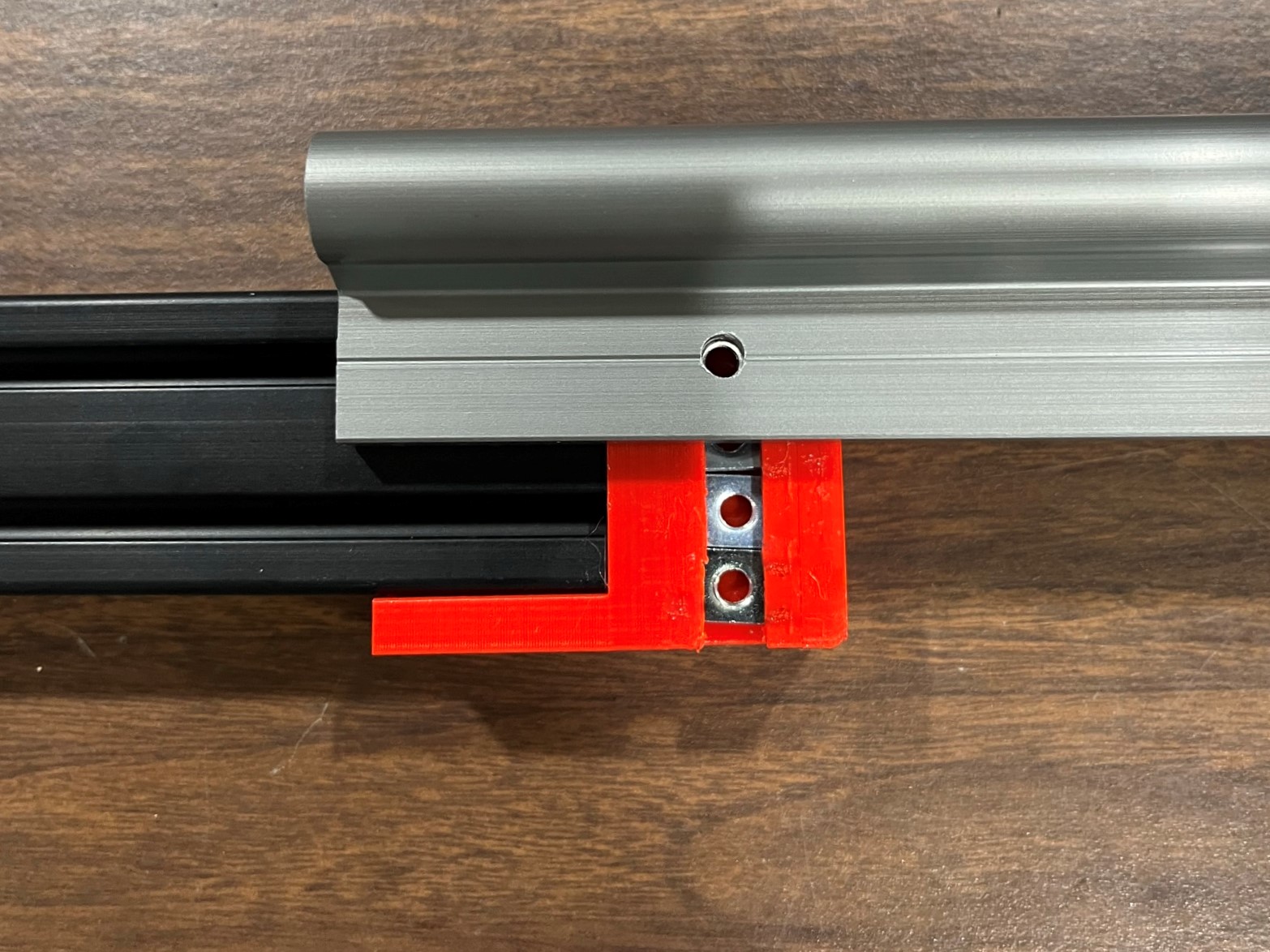
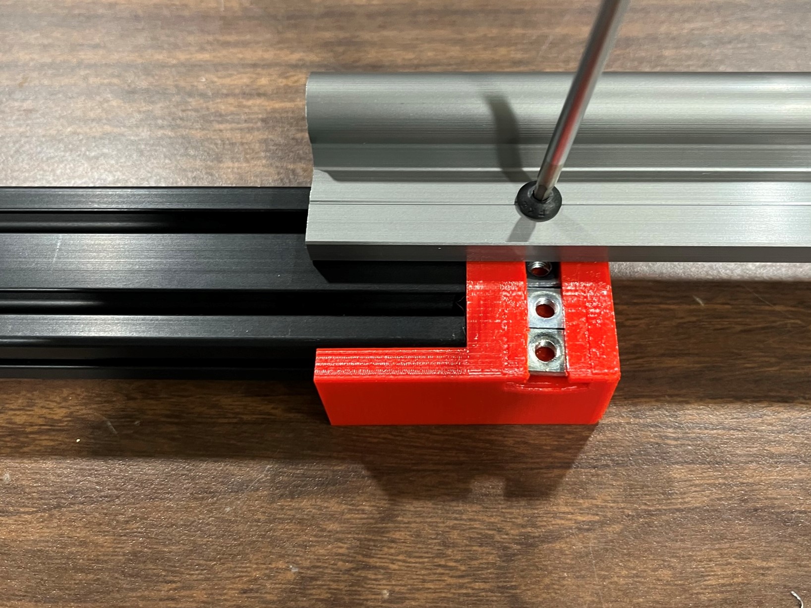
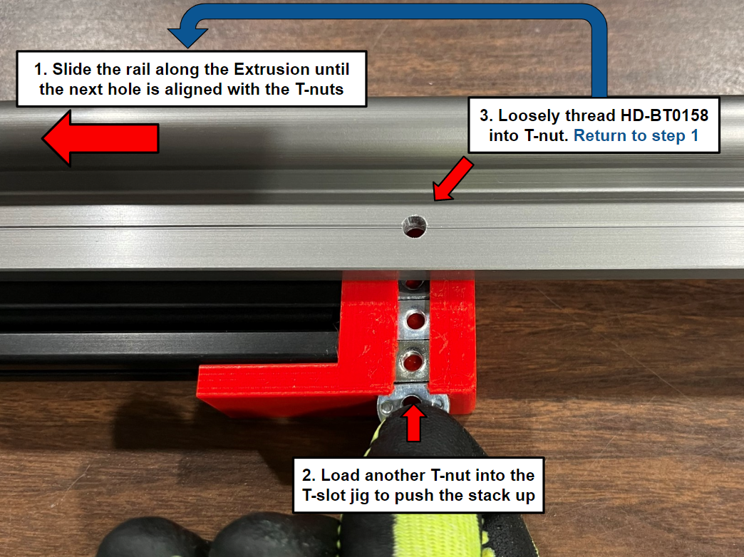
Now align the first hole in the W rail with the first T-nut inside the T-slot jig and loosely thread a M5x14 BHCS [HD-BT0158] to secure the T-nut to the W rail.
Slide the rail along the extrusion and continue this process until all 5 holes are connected to the extrusion. Load another T-nut into the T-slot jig to make sure the top T-nut is aligned with the extrusion.
Repeat for the second extrusion and rail.


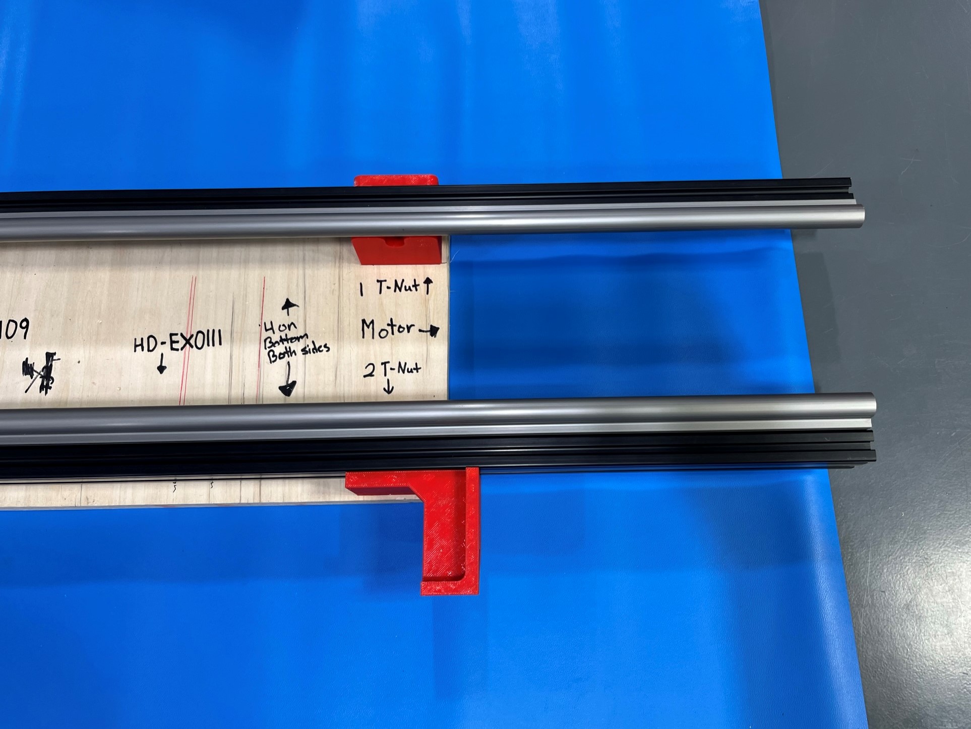
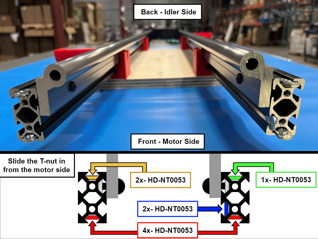
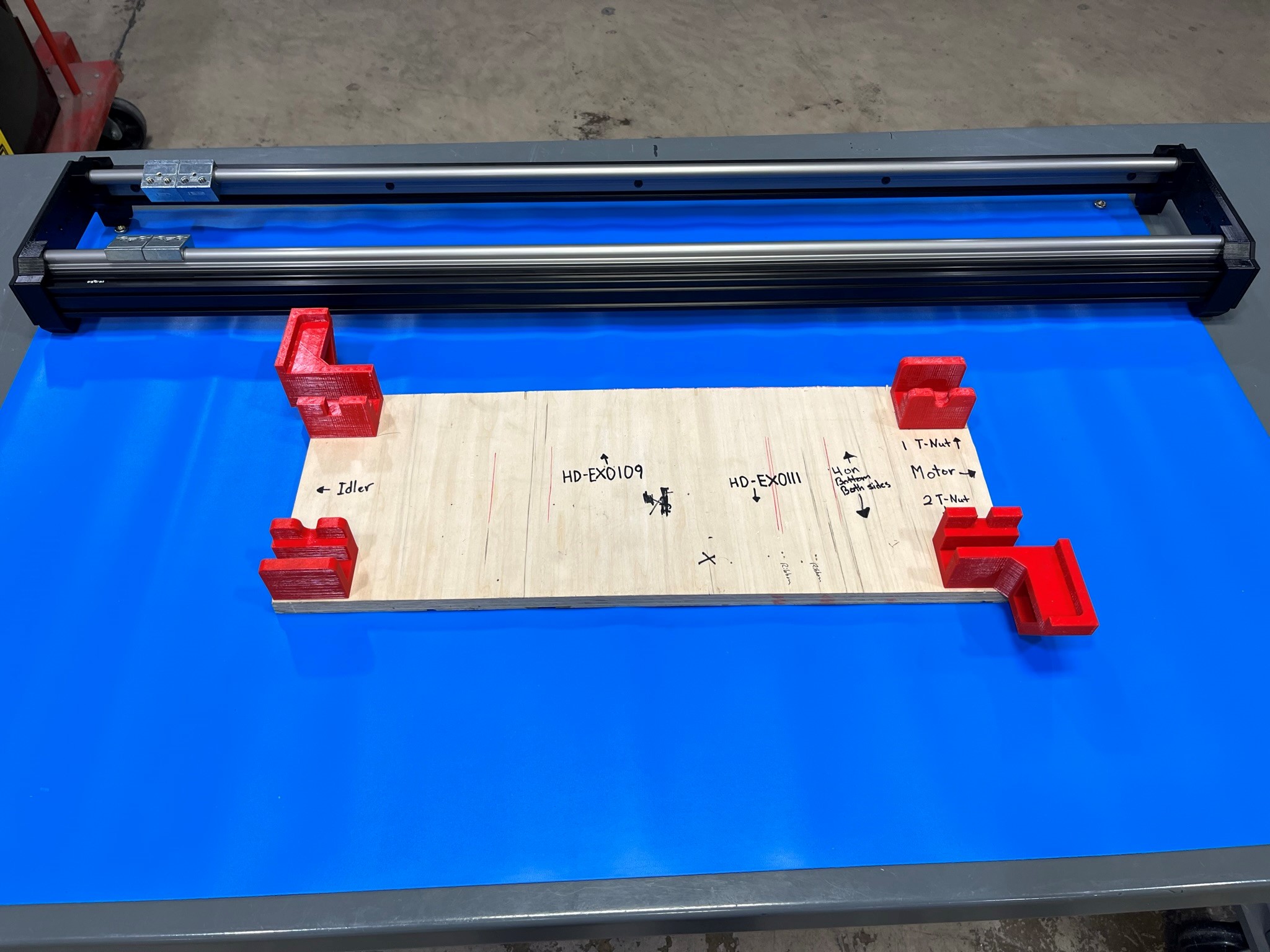
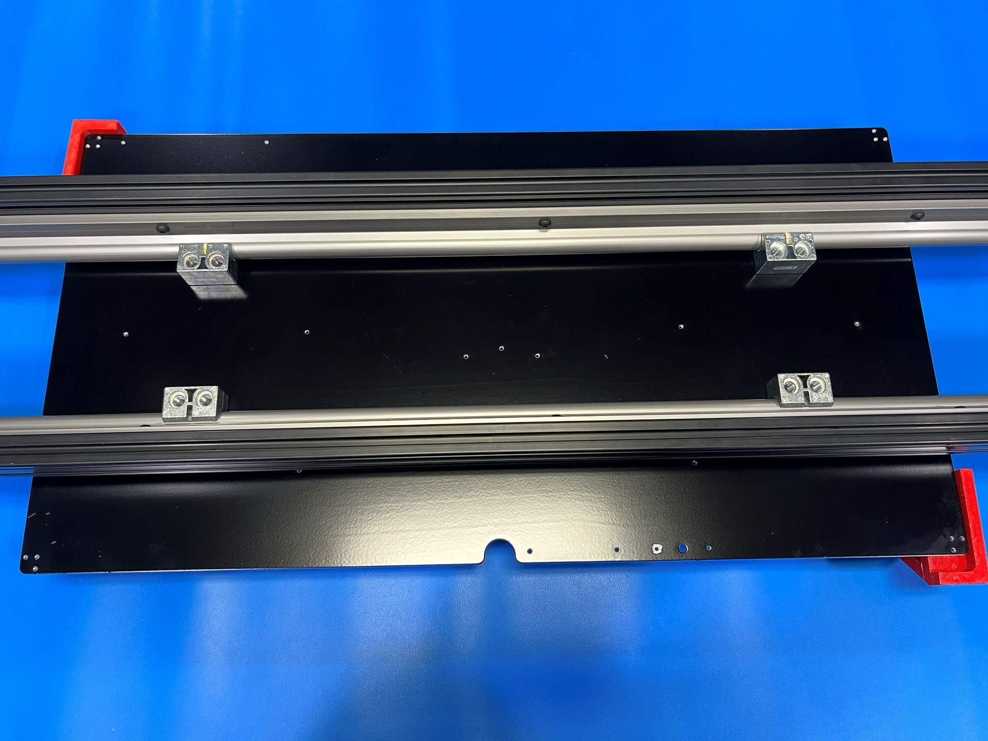
Place both extrusion and rail sub-assemblies inside the extrusion fixture, aligning the second and fourth bolt head with the cutout in the red supports.
Then reference the board and look at the motor side of the rails and follow [reference#1] to load the 13x T-nuts [HD-NT0053] into the extrusions.
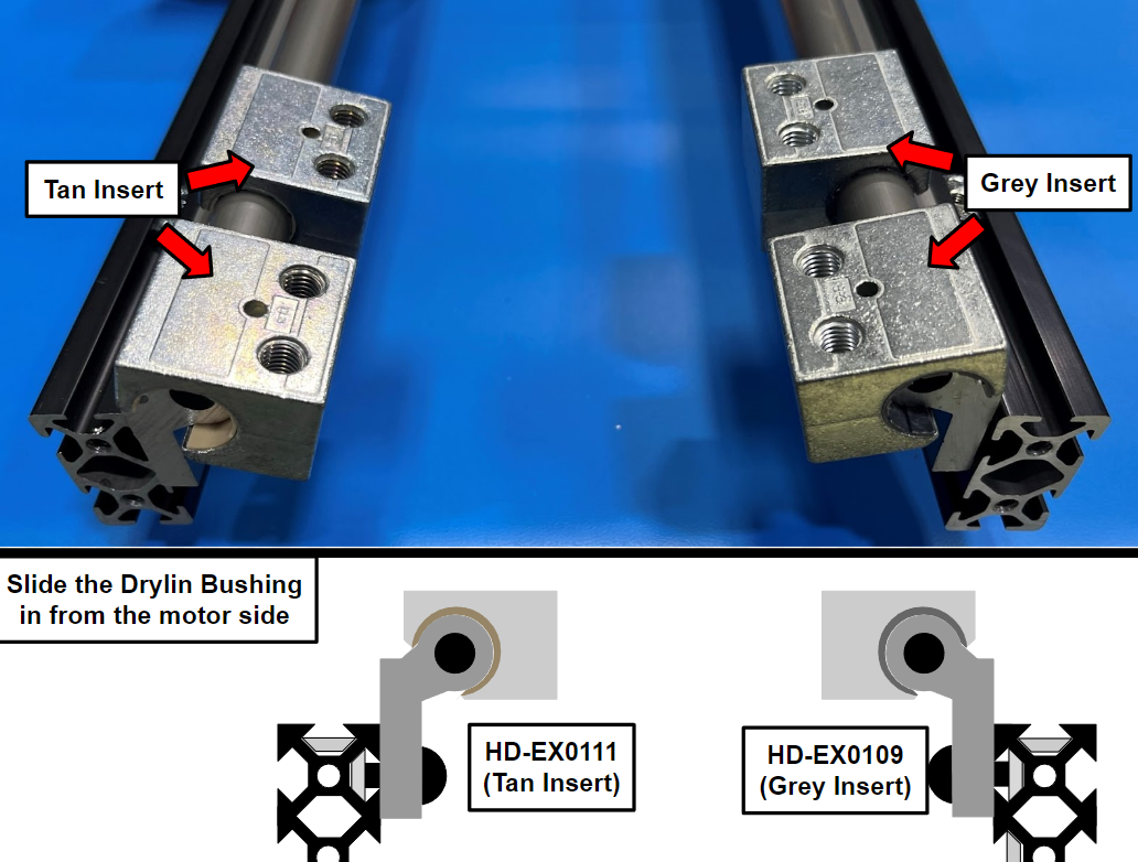
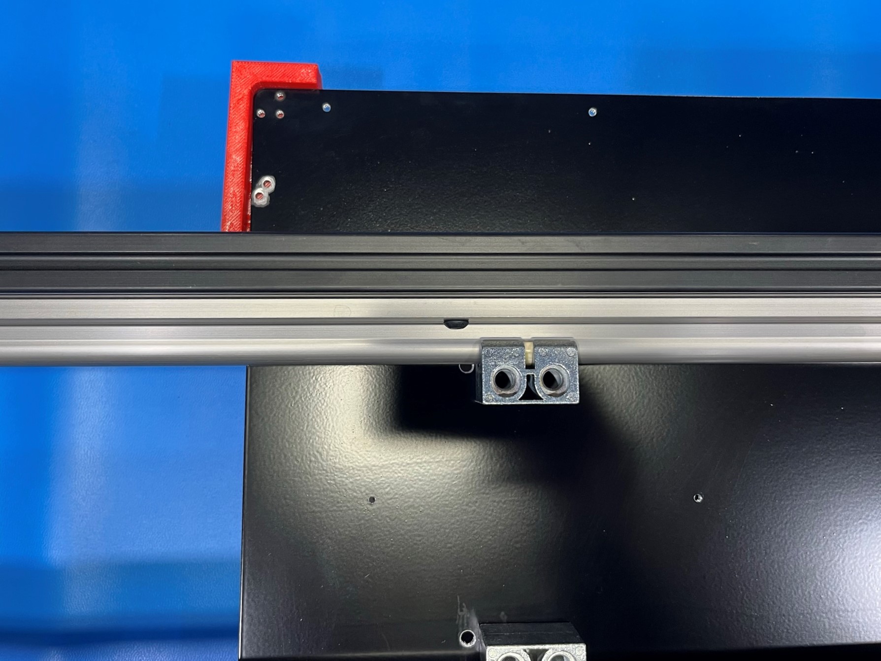
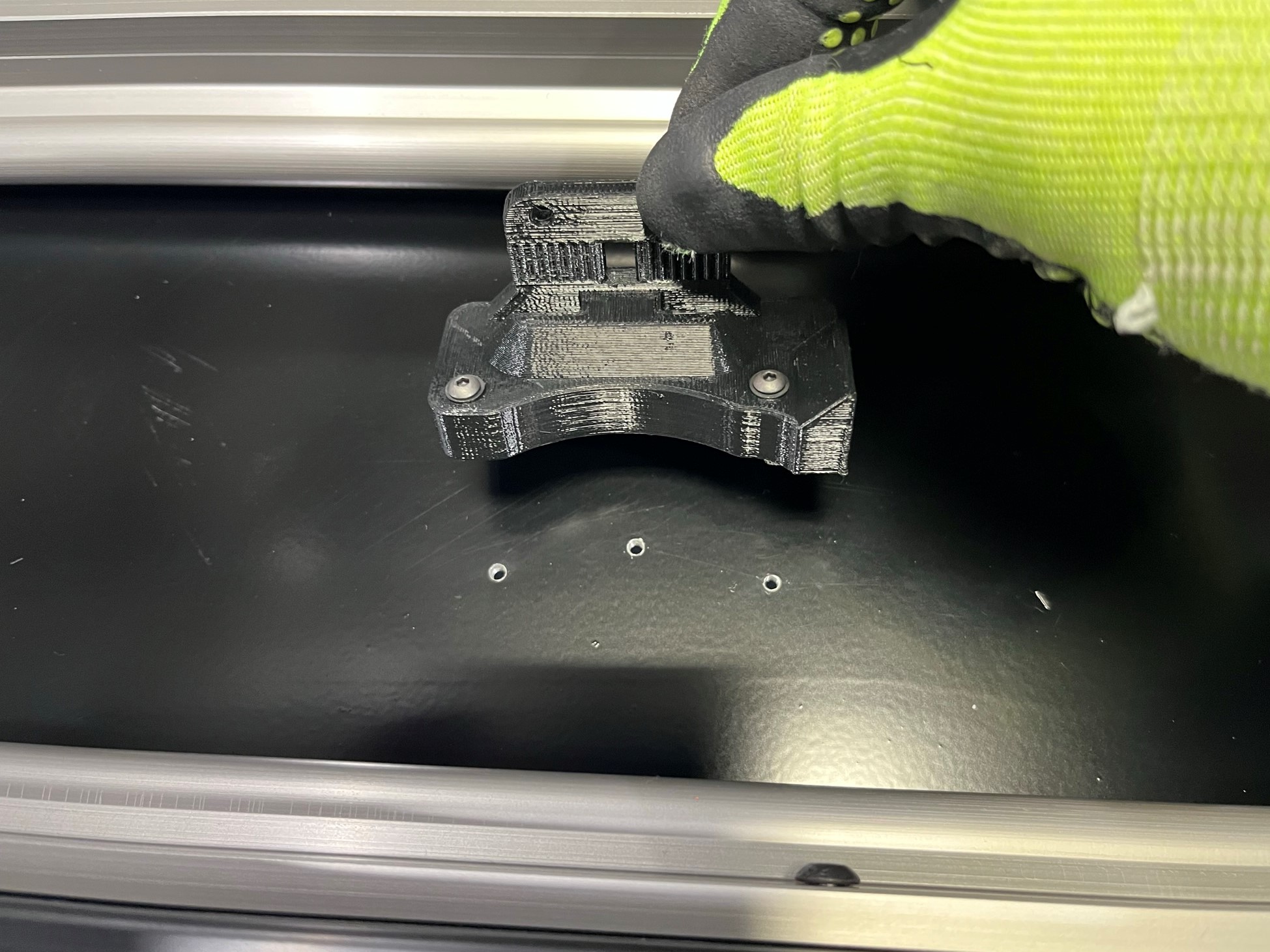
Now following the same process follow [reference#2] to slide the Drylin bushings onto the rails. You will use 2x Drylin bushings (grey insert) [HD-EX0109] and 2x Drylin bushing (tan insert) [HD-EX0111].
Make sure to keep the grey and tan bushings on different rails!
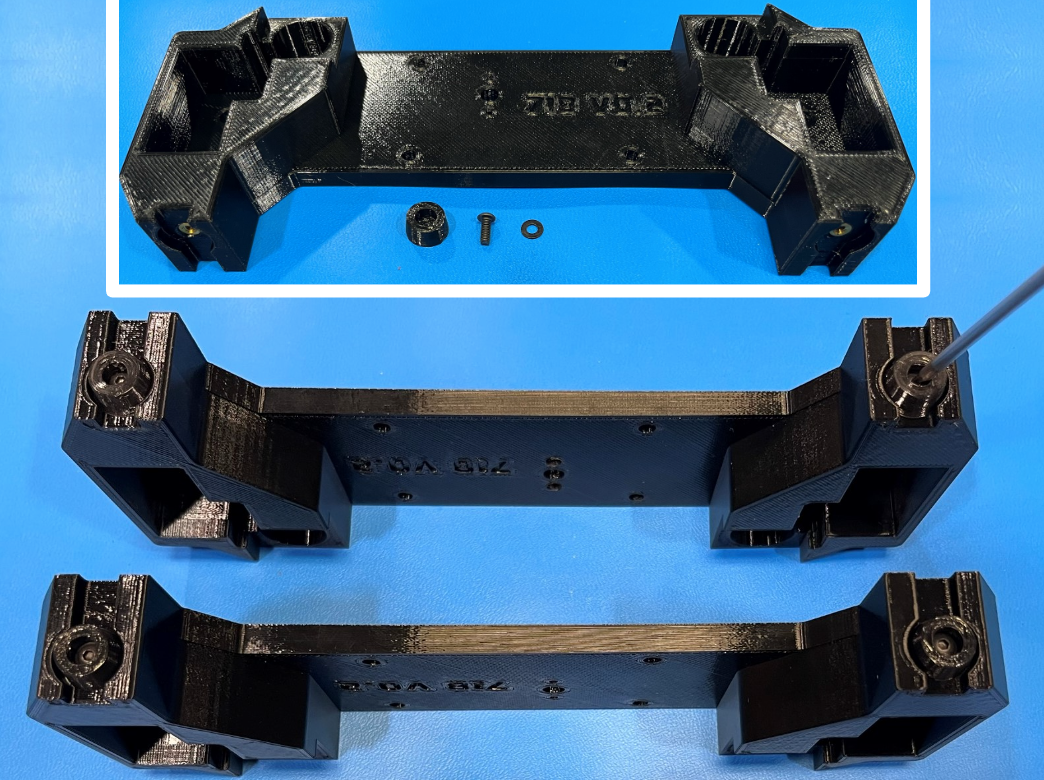
Then install 2x flexy bed feet [PP-GP0238] to the bottom of the combined Y end [PP-GP0718] using 2x M3x8 BHCS [HD-BT0137] with M3 washers [HD-WA0038]. Then repeat for the second combined Y end.
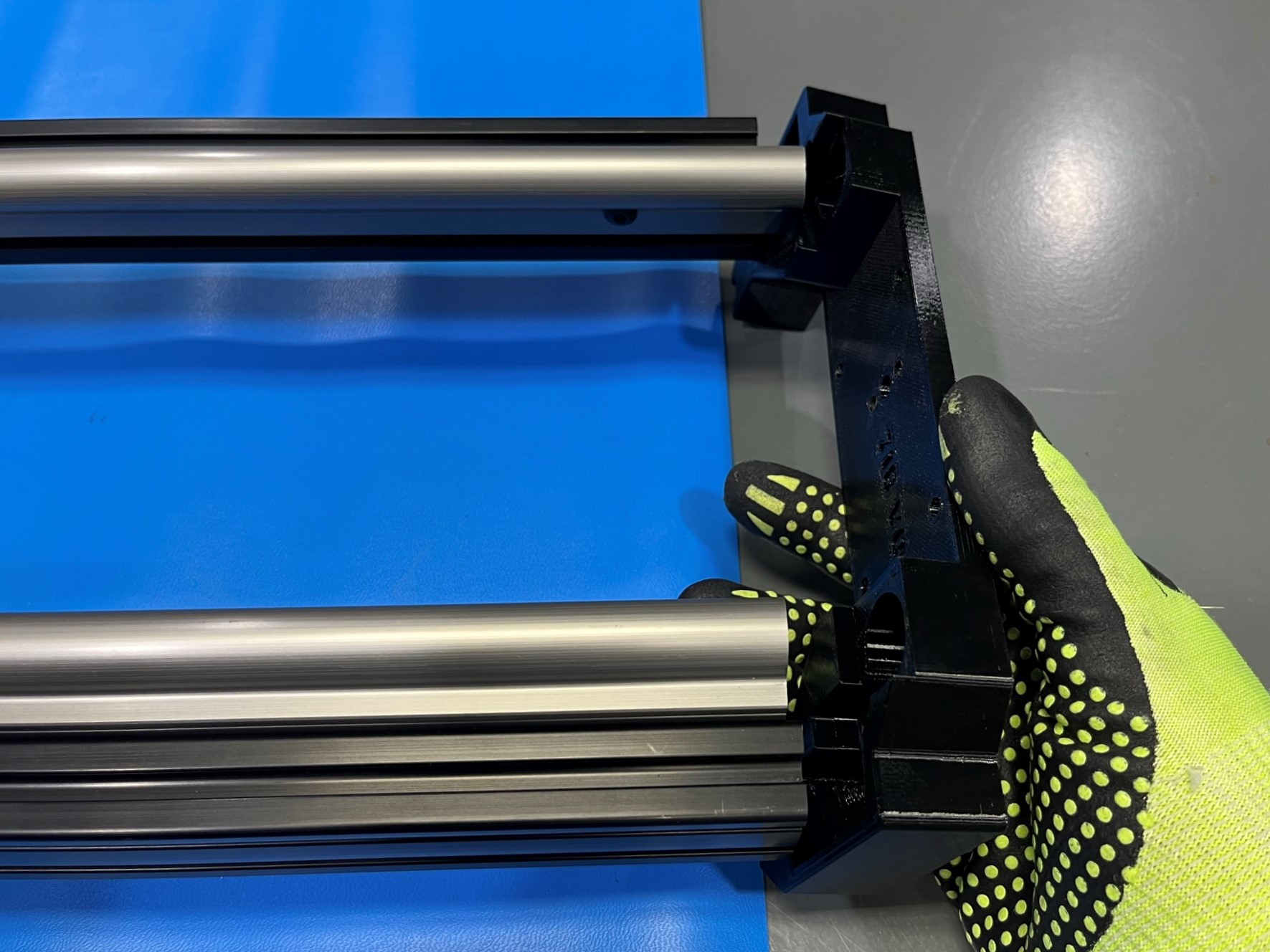
Slide the combined Y end with inserts over the idler end of the extrusion rail sub-assemblies. Then align the long bed Y end plate [PP-FP0226] with the combined Y end making sure the middle holes align.
Then use 4x M5x20 BHCS [HD-BT0272] with M5 washers [HD-WA0040] to secure the Y end plate to the extrusions, only finger-tighten these bolts for adjustments later on.
Repeat for the motor side.

Remove the long bed frame from the extrusion fixture.
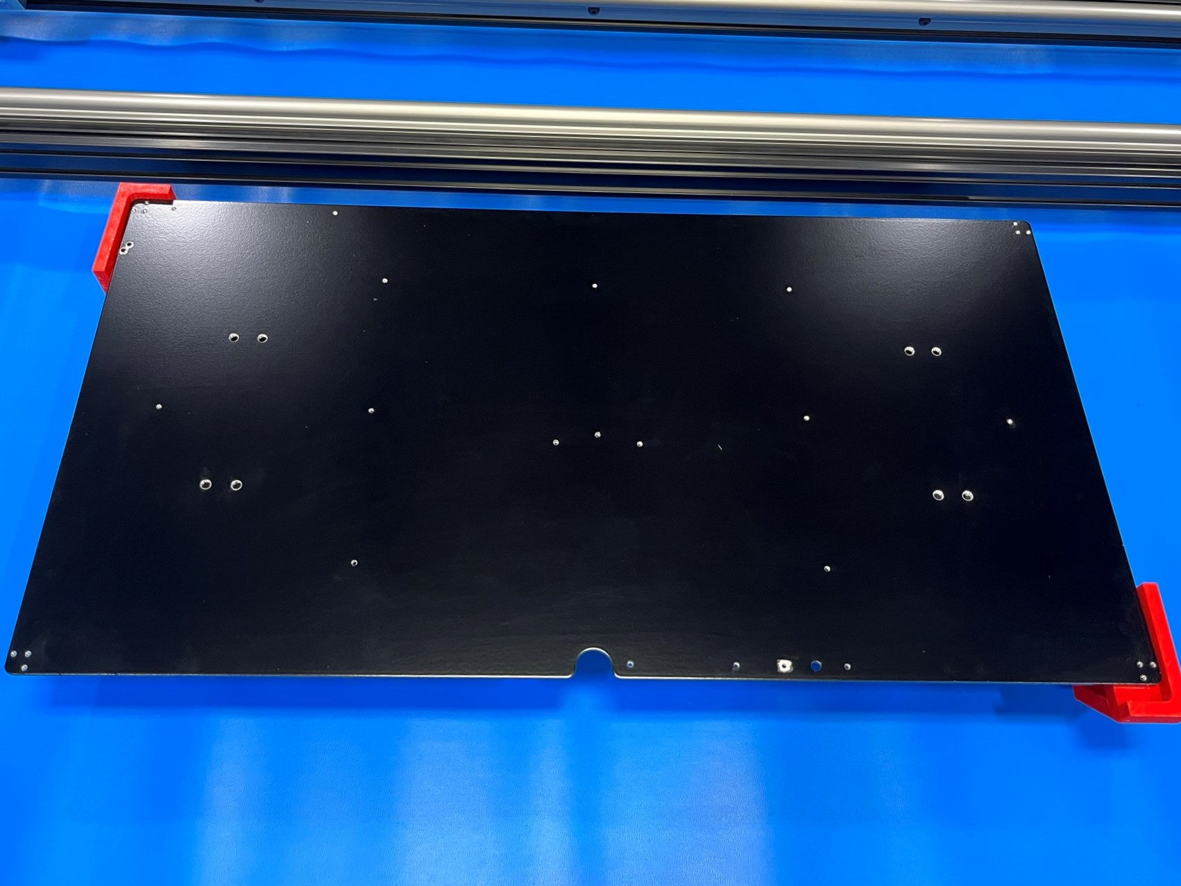
Take the long bed plate [PP-MP0230] and find the side that has exposed aluminum and place it inside the extrusion fixture with the exposed aluminum facing up.
Then flip the long bed frame over and place it on top of the bed plate making sure the bushing rest on the bed plate.
Before securing the bed plate to the long bed frame make sure the bushing with the grey inserts are on the same side as the round cutout on the bed plate.
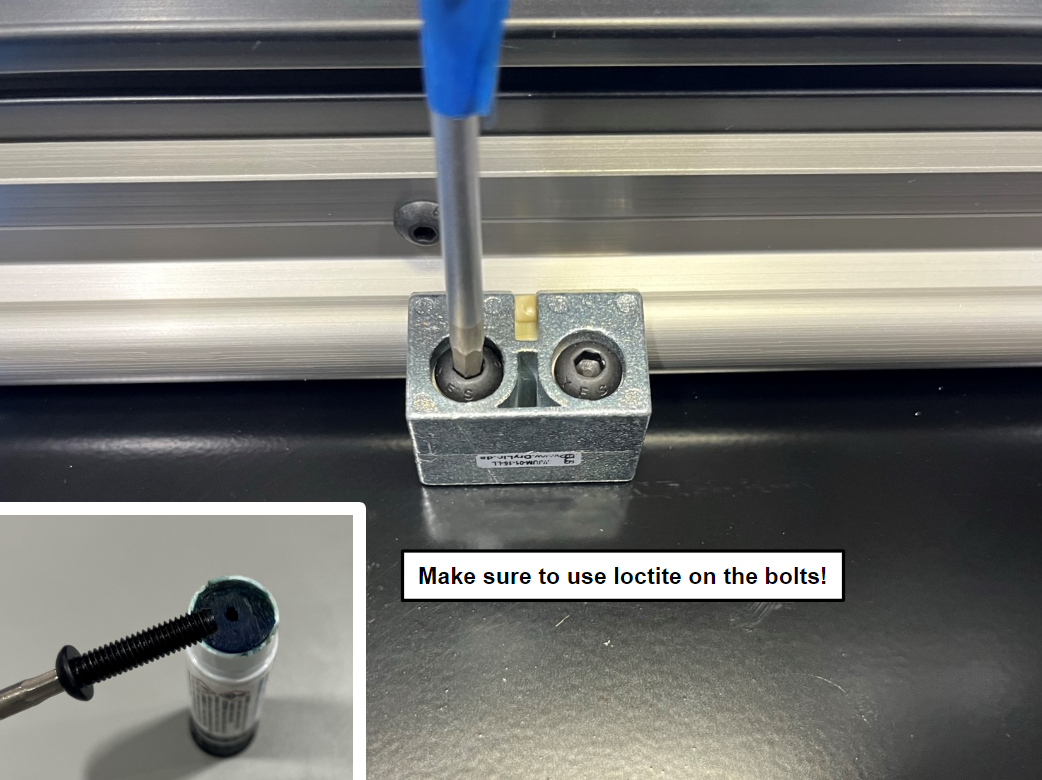
Now align the bushings with the holes in the bed plate and use 8x M6x25 [HD-BT0277] with loctite to secure the bushings. Make sure to leave the bolts a little loose


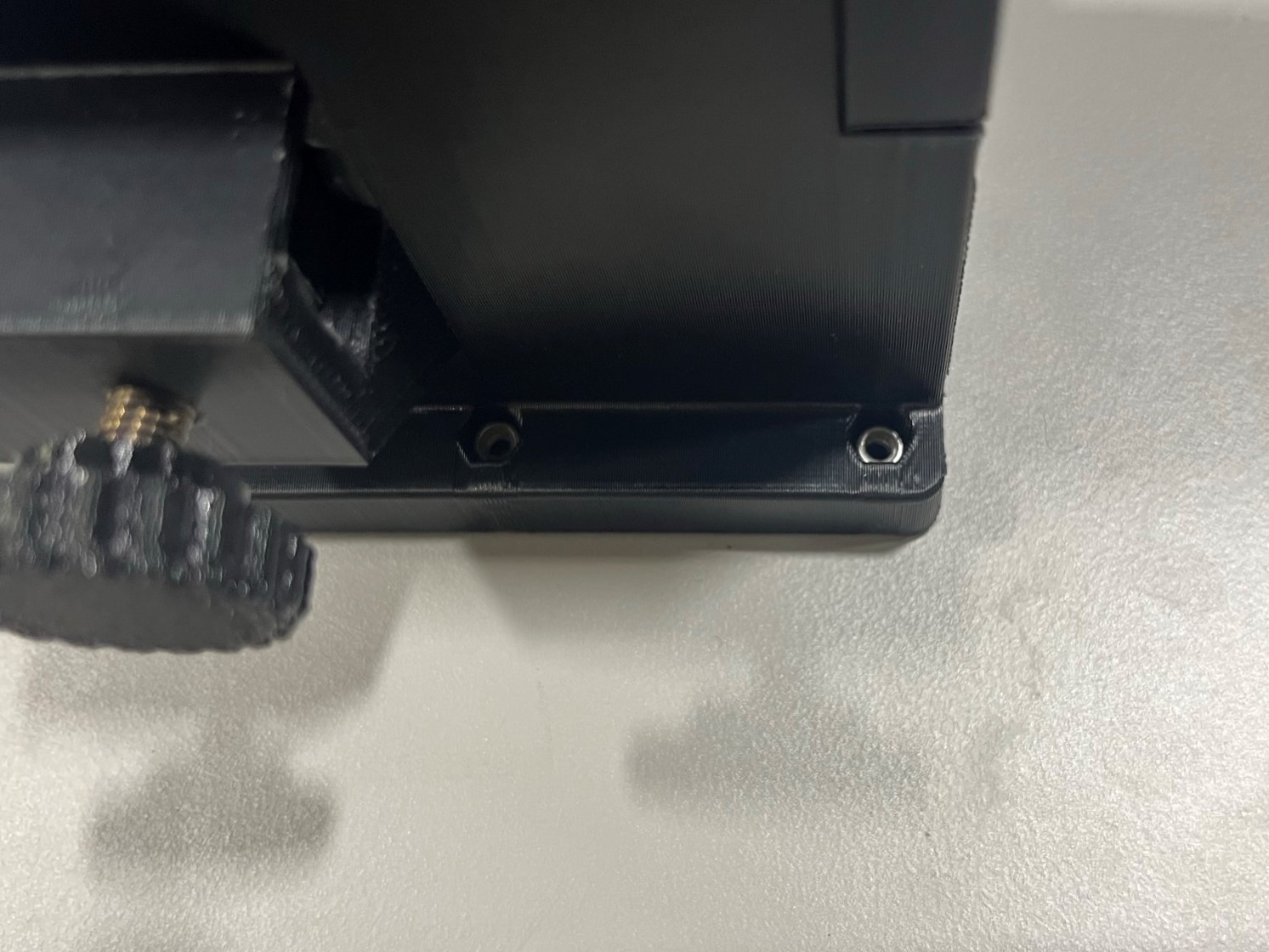
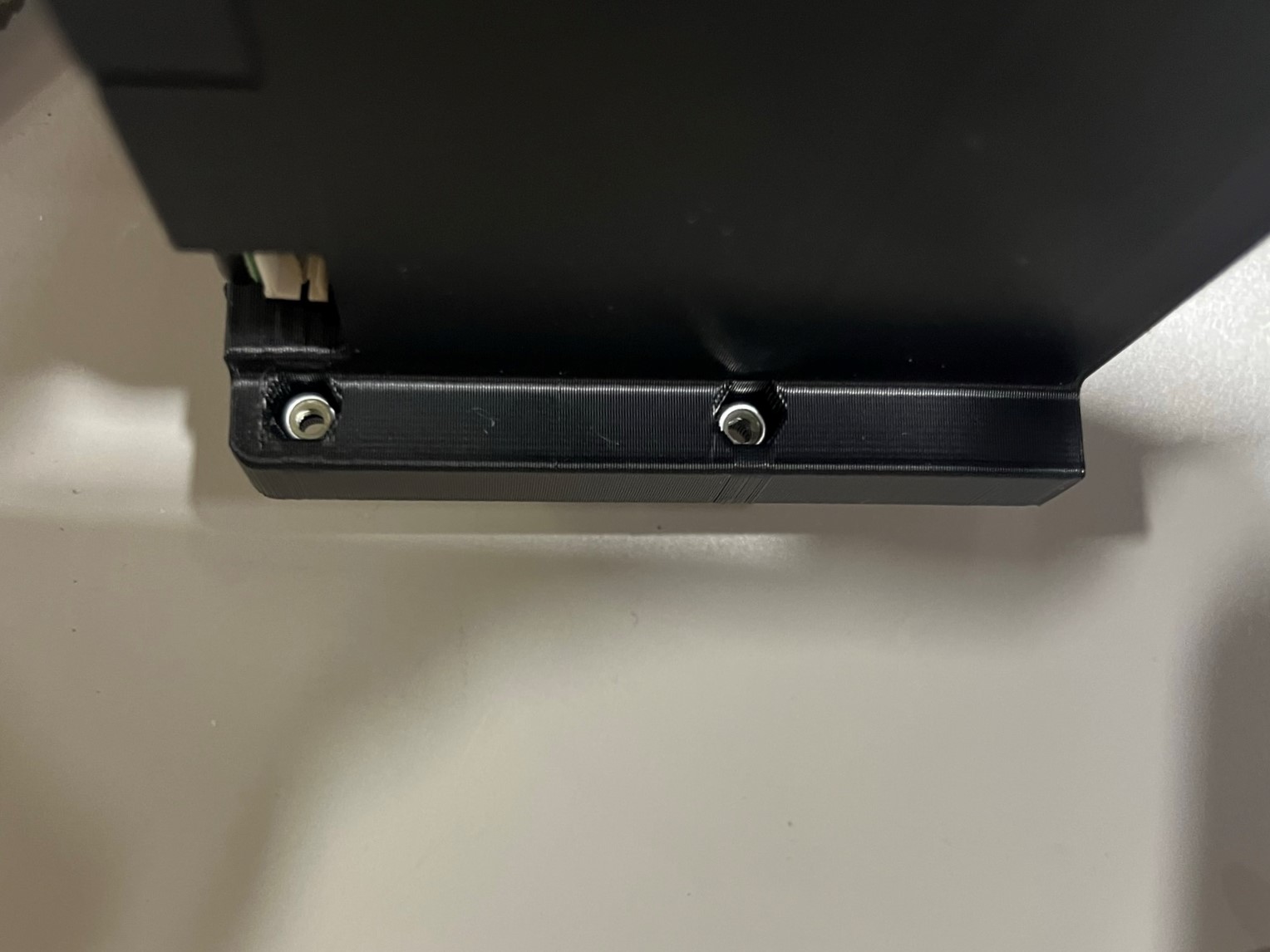
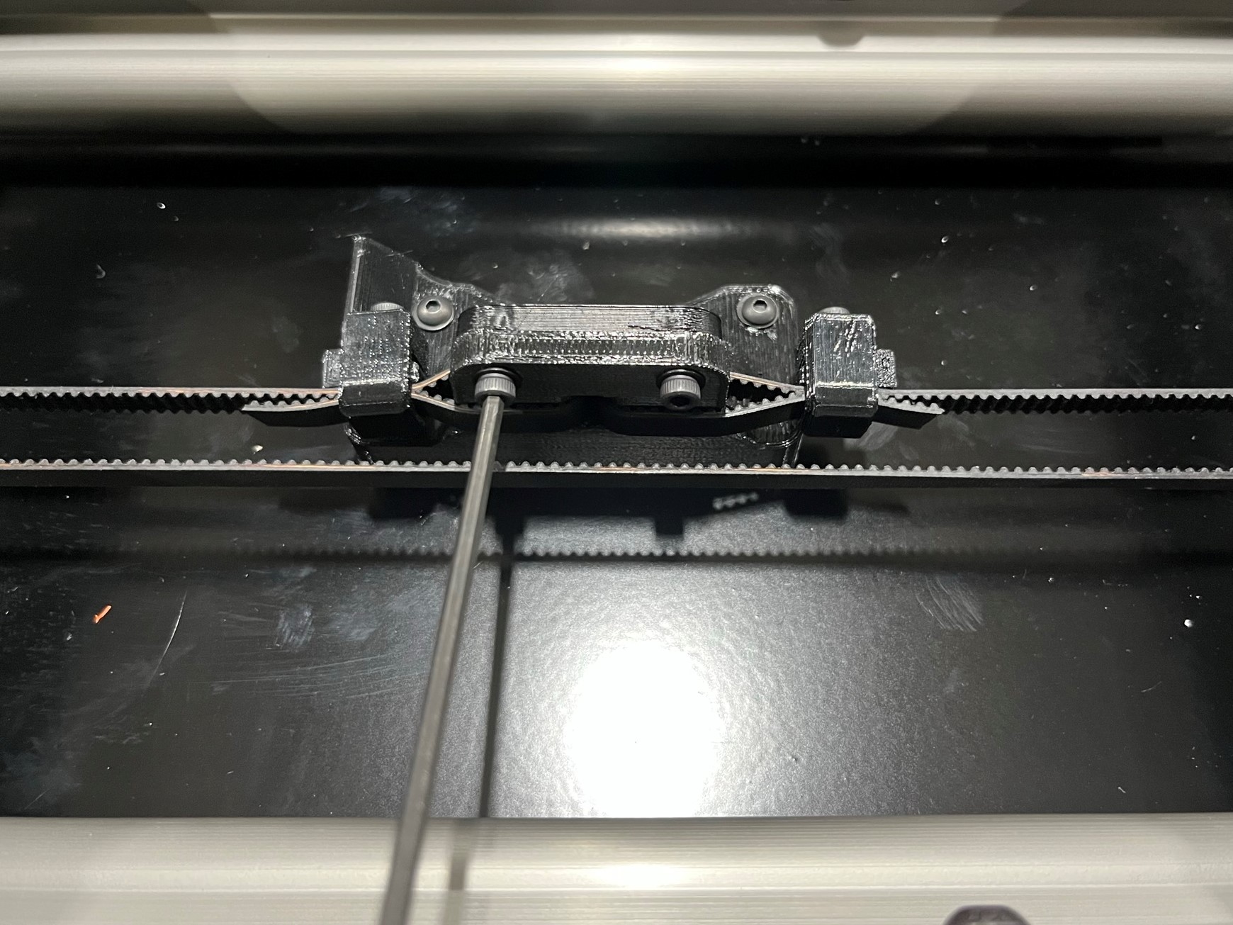
Place the 2-1 Y belt mount [PP-GP0719] on the bed and align it with the holes in the middle of the bed plate. The belt mount will cover up the middle hole but use the two on the ends.
Then use 2x M3x16mm [HD-BT0256] with M3 washers [HD-WA0038] to secure the Y belt mount to the bed plate. Make sure to apply loctite to end of bolt threads!
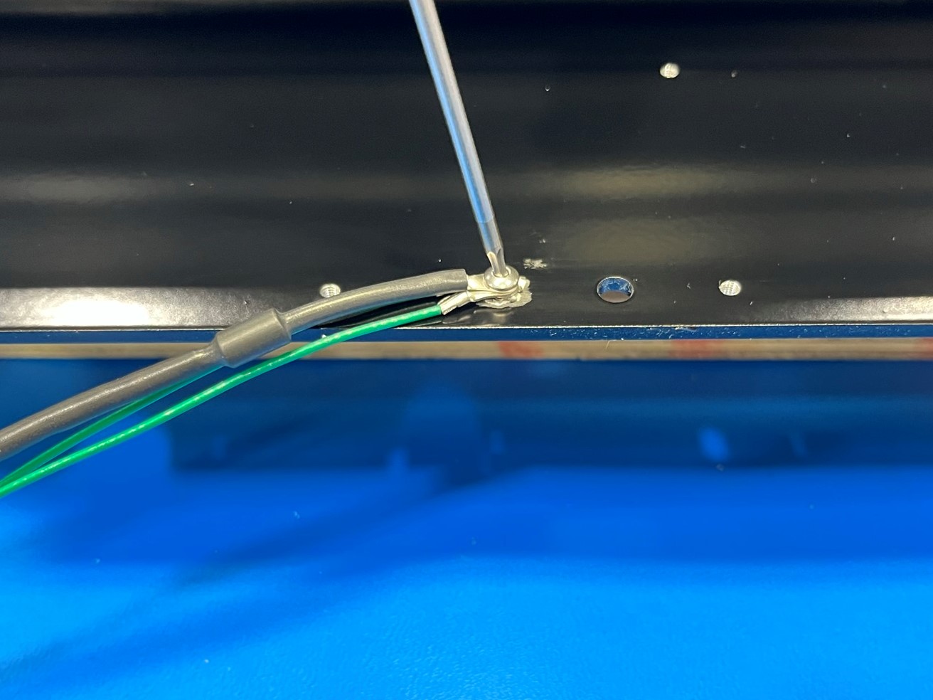
Now using 1x M3x8 BHCS [HD-BT0104] with a M3 lock washer [HD-WA0035] secure the bed extension harness [EL-HR0146] to the bed plate make sure the lock washer is between the harness and the bed plate. Make sure to use the hole that has exposed aluminum around it.


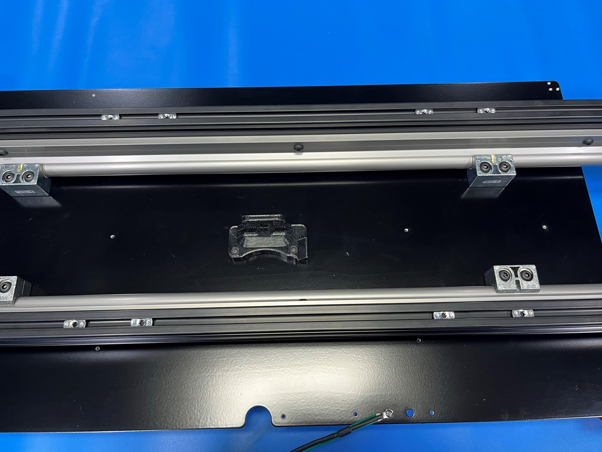
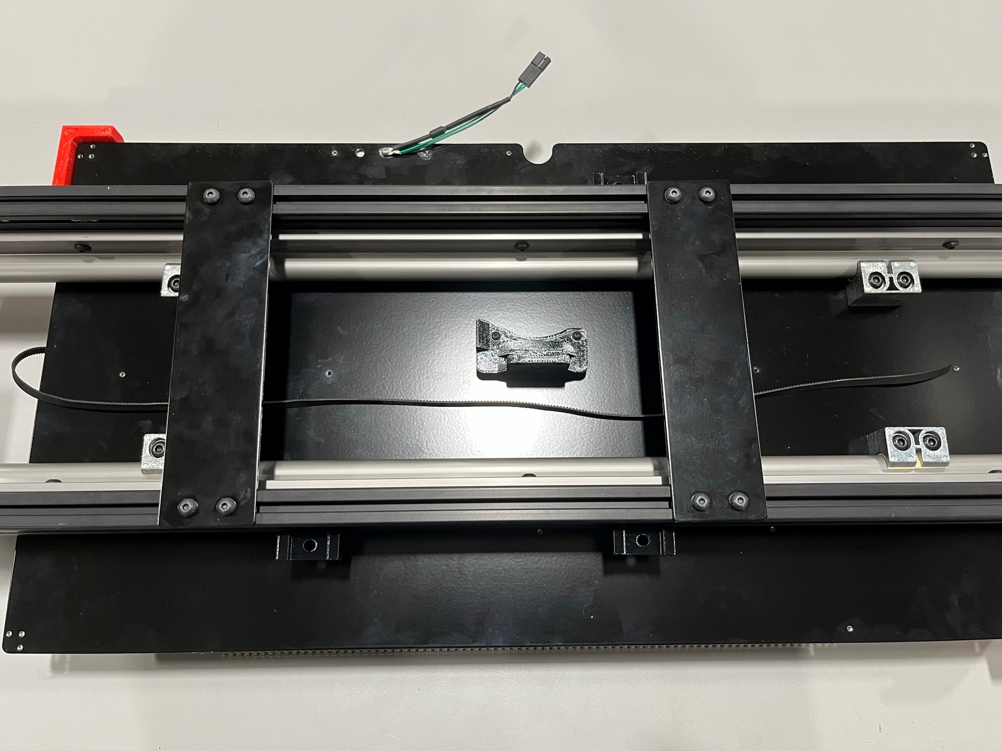
Before installing the bottom supports make sure each extrusion has 4x T-nuts, then group them into pairs. This will help when installing the bottom supports.
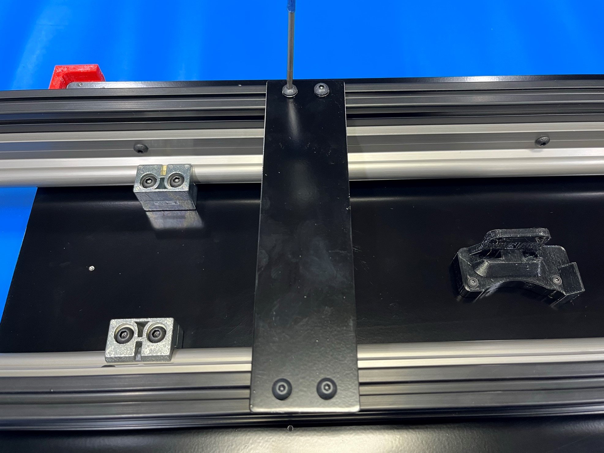
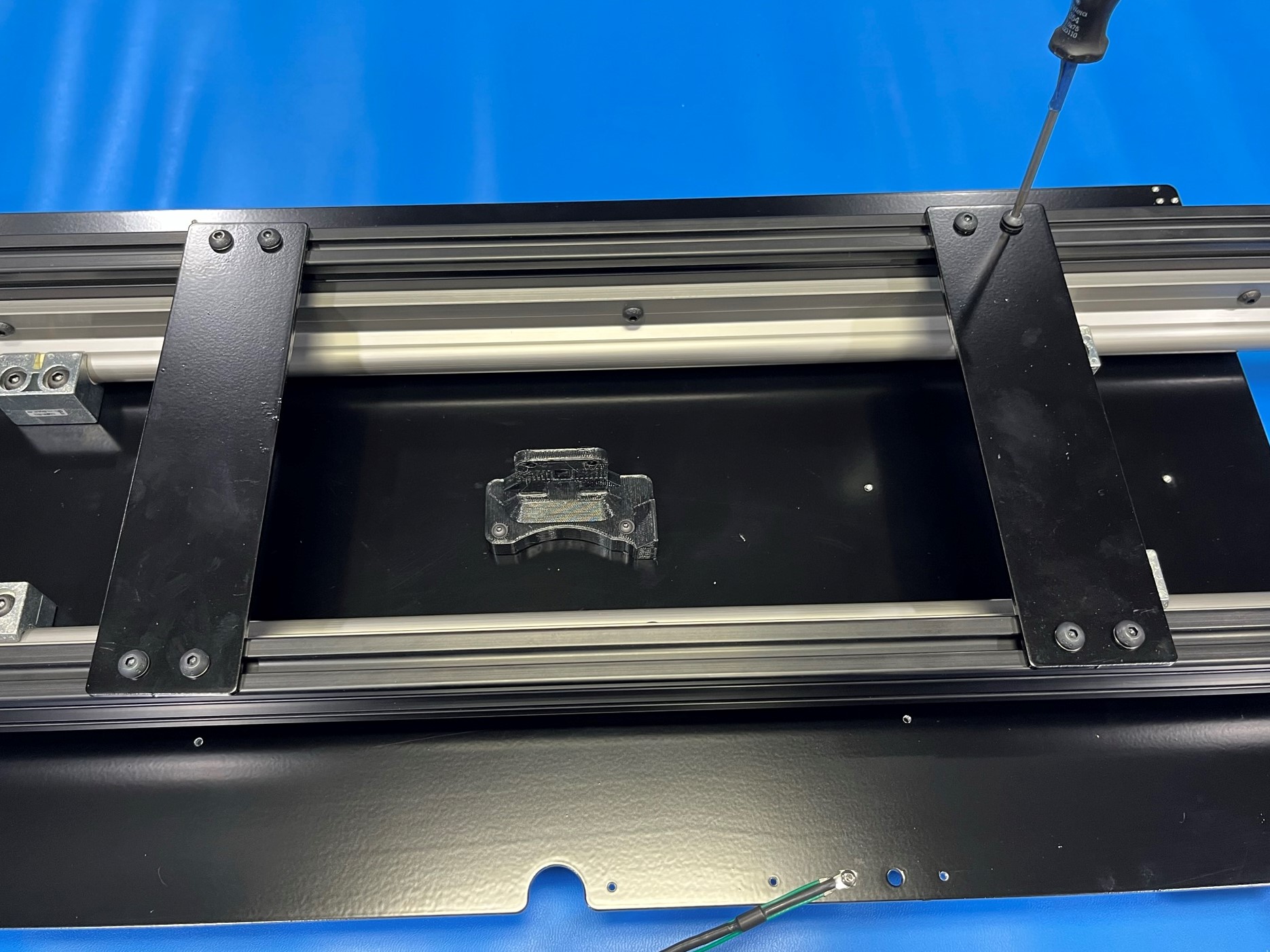
Using 4x M5x10 BHCS [HD-BT0073] with M5 washers [HD-WA0040] loosely attach 1x long bed bottom support brace [PP-FP0227] to the extrusions. Make sure there is 4x T-nuts to either the left or right of this bottom support.
Then repeat for the second long bed bottom support brace.
Make sure you are able to slide the bottom supports along the extrusions, you may need to loosen the bolts for this.
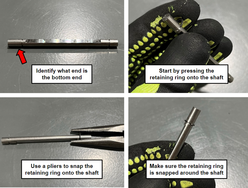
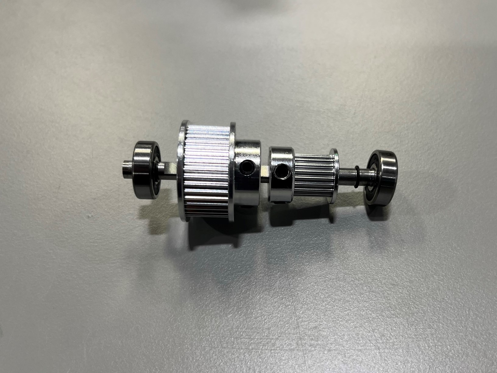
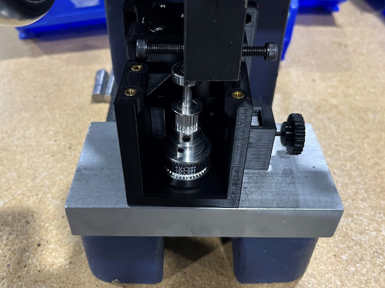
Follow [reference#3] to place the retaining ring [HD-WA0014] on the bottom side of the 5x200mm rotary shaft [HD-RD0089].
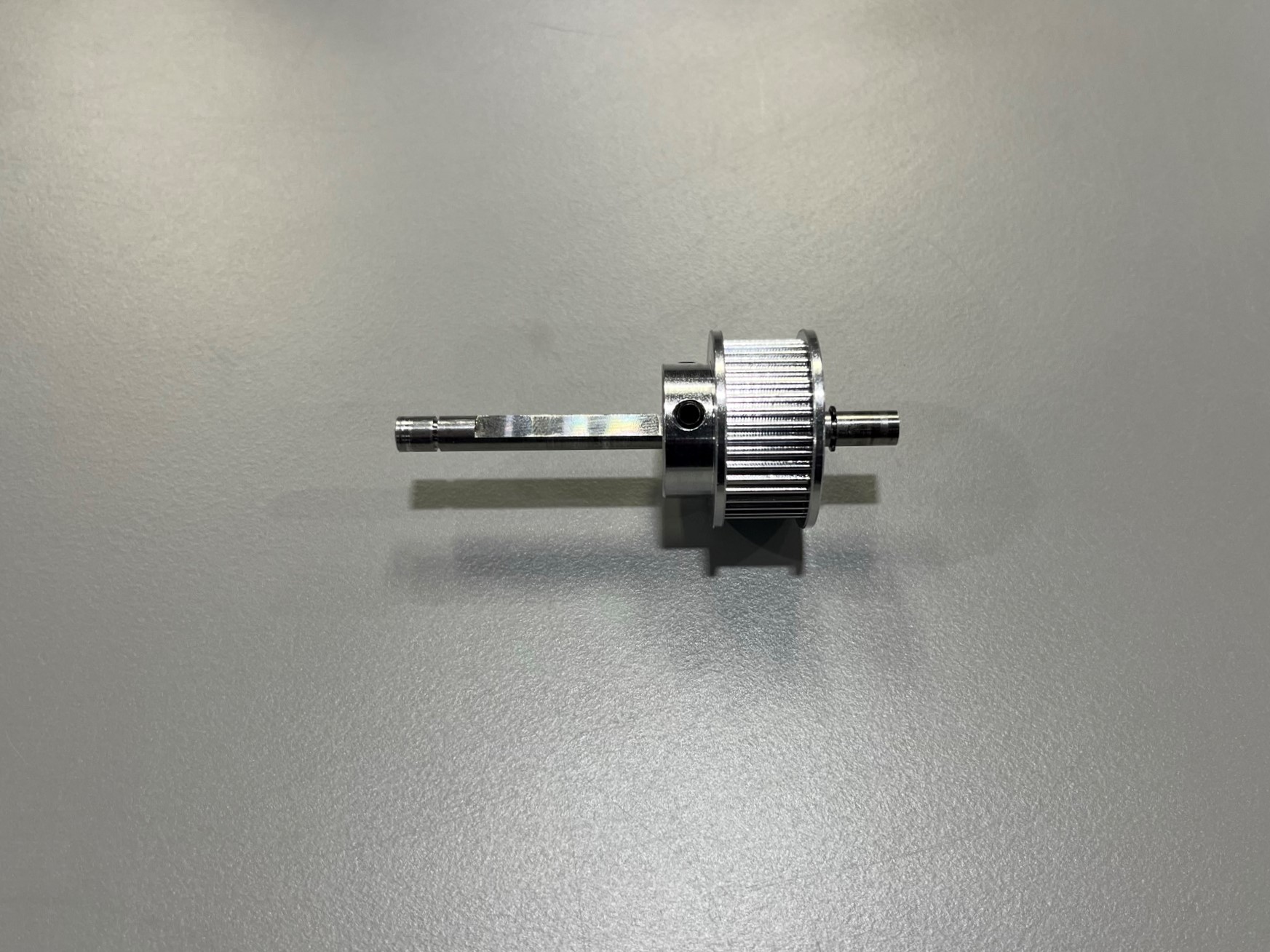
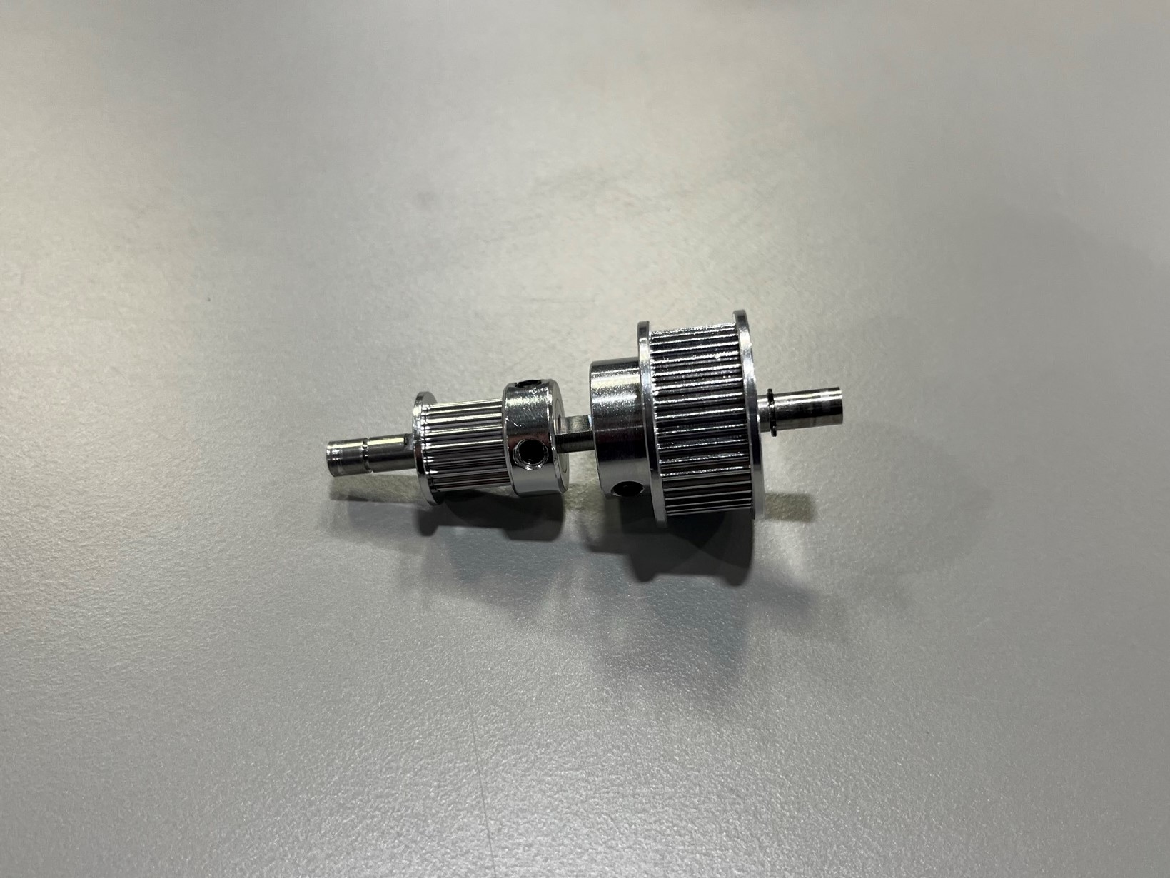
Then take the 2GT 40T timing pulley [HD-MS0300] and slide it onto the rotary shaft, make sure to start with the larger side of the timing pulley.
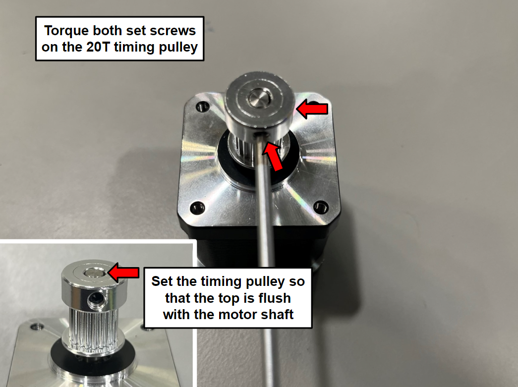
Now slide the 2GT 20T timing pulley [HD-MS0070] onto the rotary shaft, make sure to start with the side that has the set screws.
Once both timing pulleys are on the rotary shaft place the second retaining ring on the top end of the rotary shaft, use the same process as the first retaining ring.
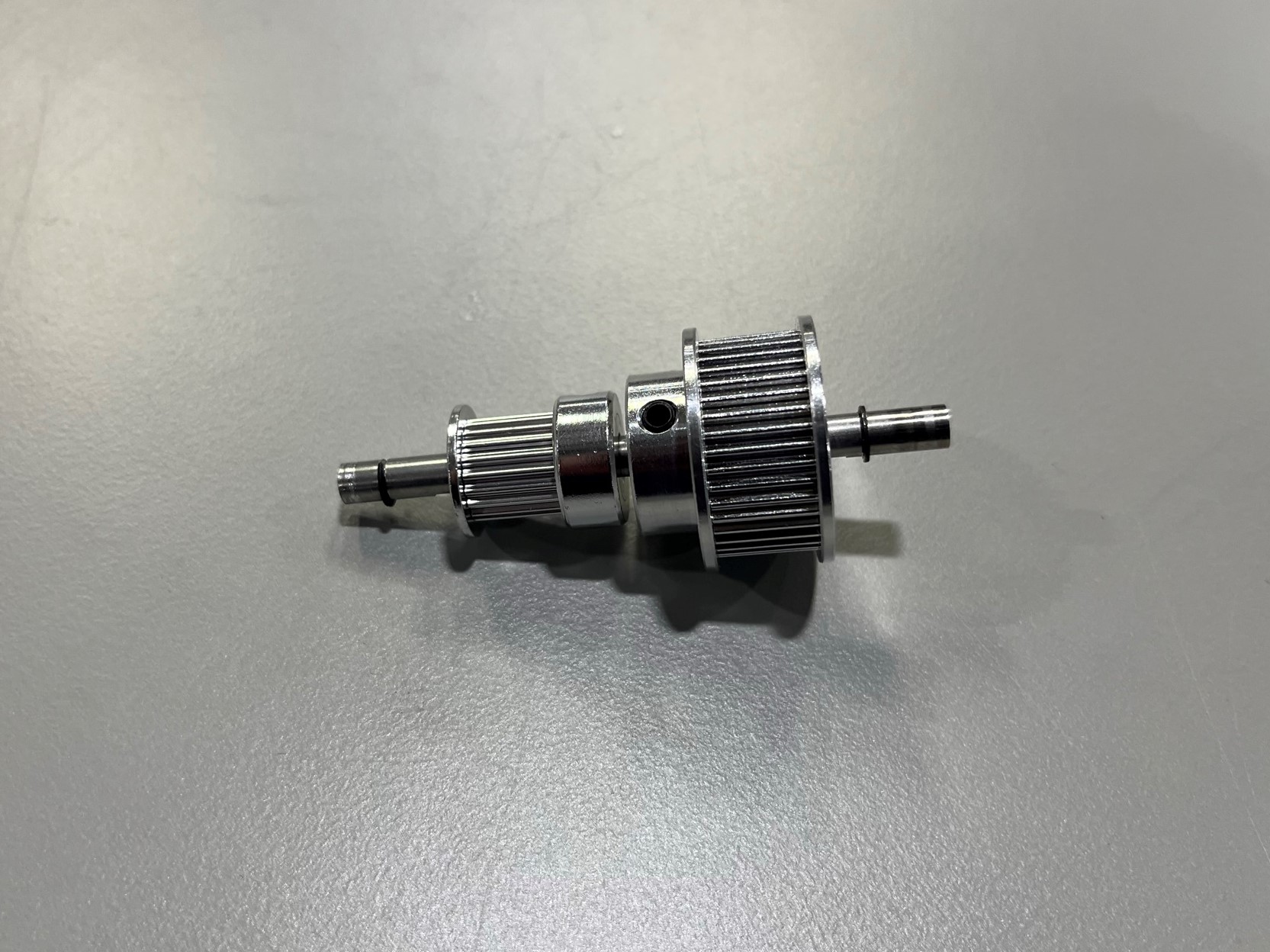
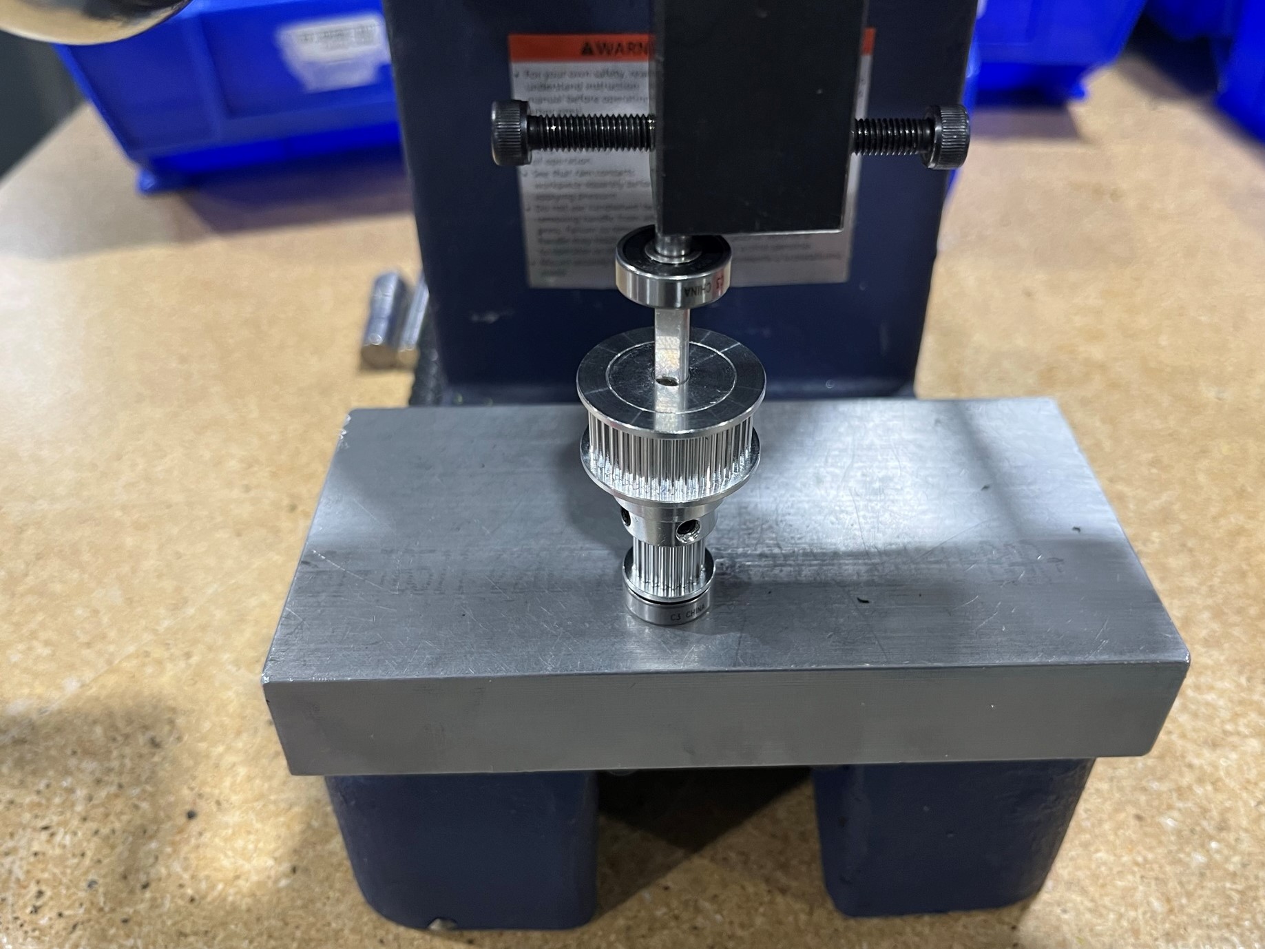
Now slide 2x rubber sealed bearings [HD-MS0411] on the rotary shaft, slide one onto each end of the shaft until they hit the retaining rings.
If the bearings get stuck on the shaft before they hit the retaining ring use the press to gently press the bearings onto the shaft.
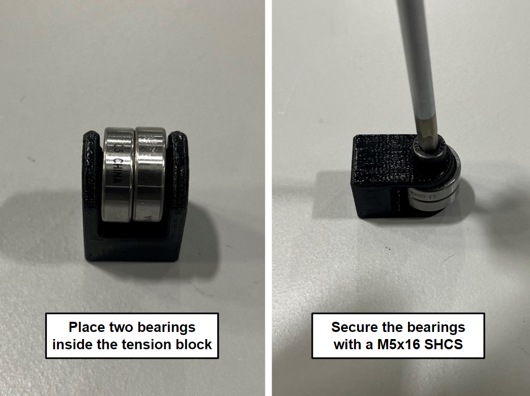
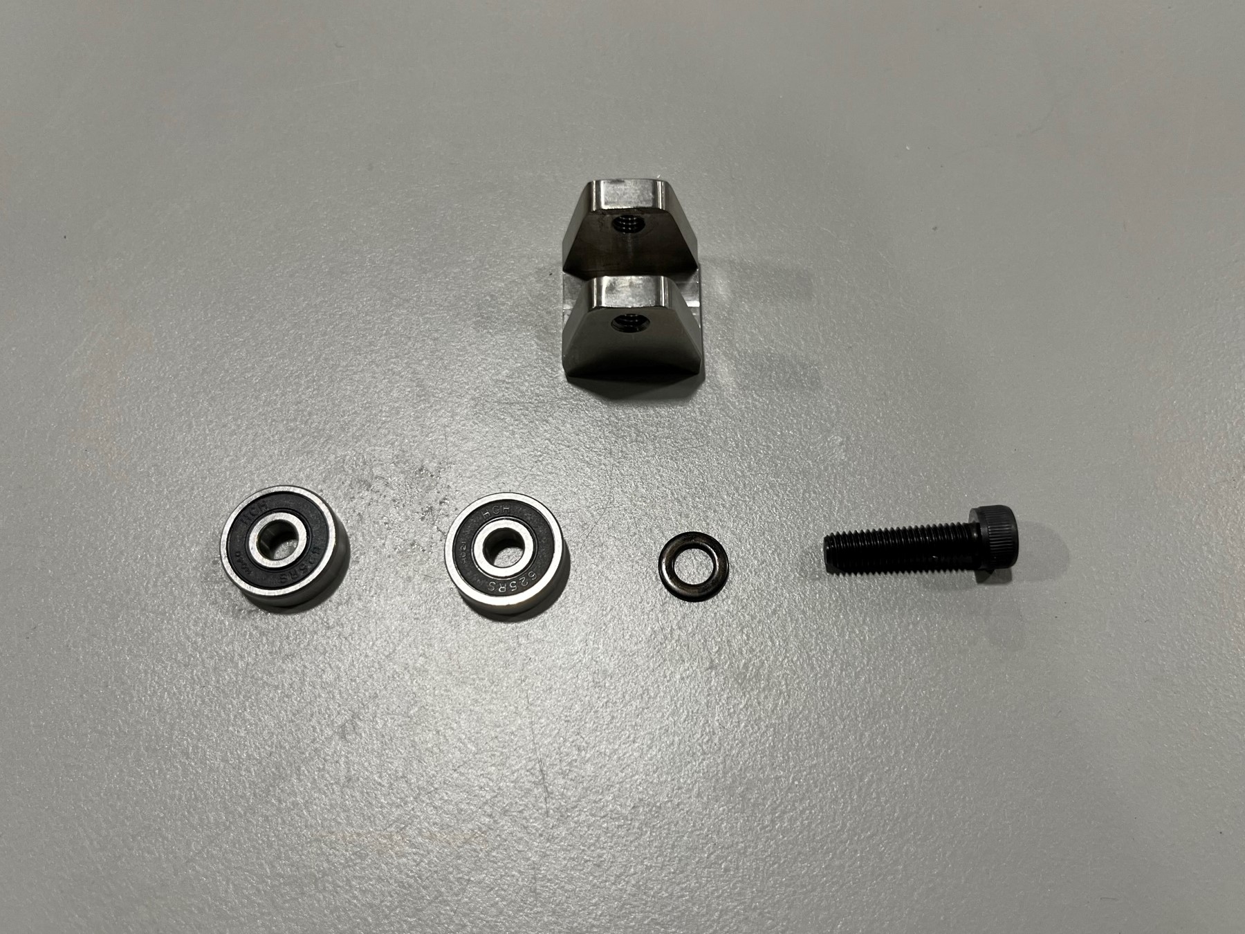
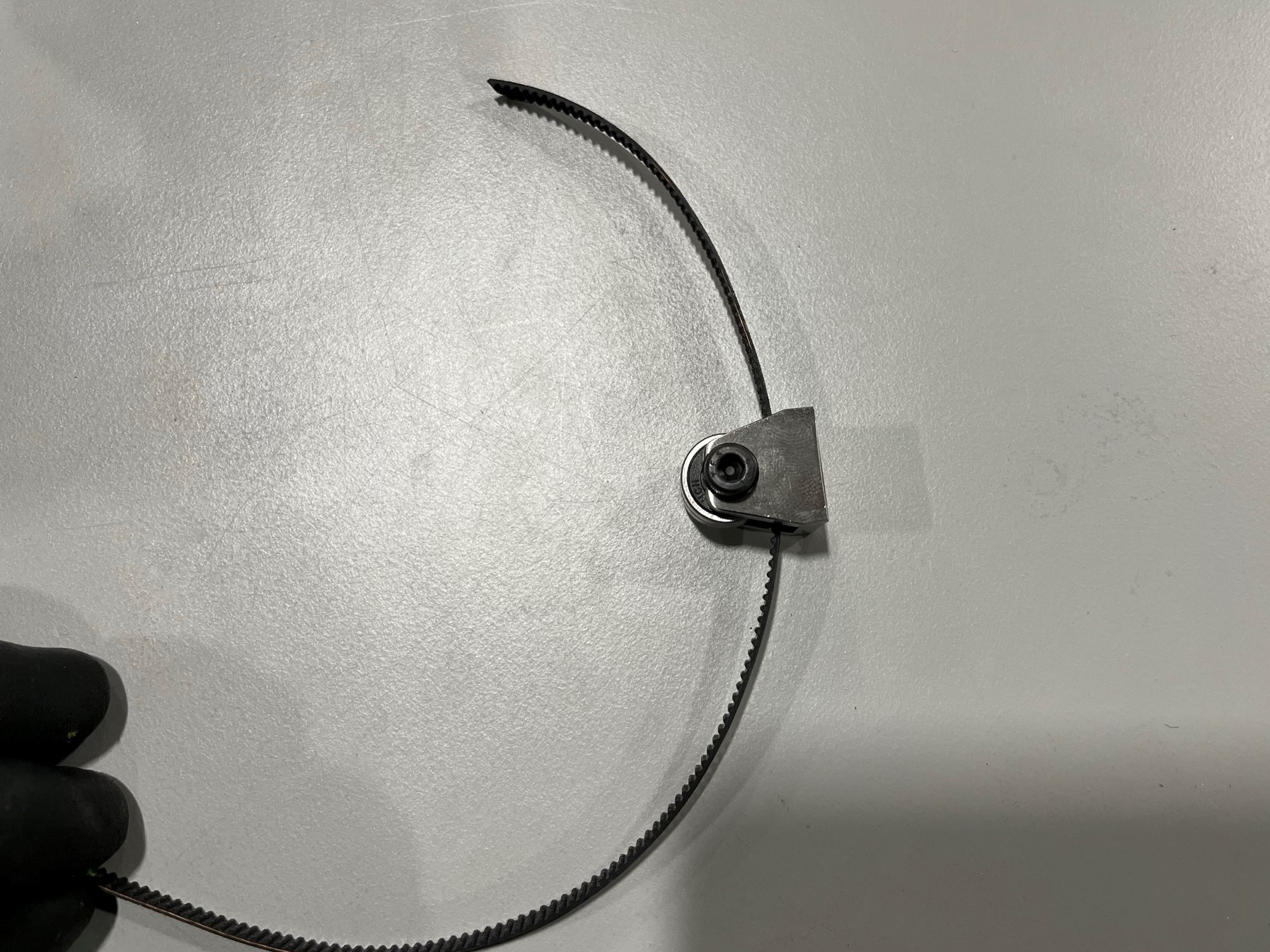
Place 2x rubber sealed bearings [HD-MS0411] inside the tension block [PP-GP0723] then use 1x M5x16 SHCS [HD-BT0175] to secure the bearings.
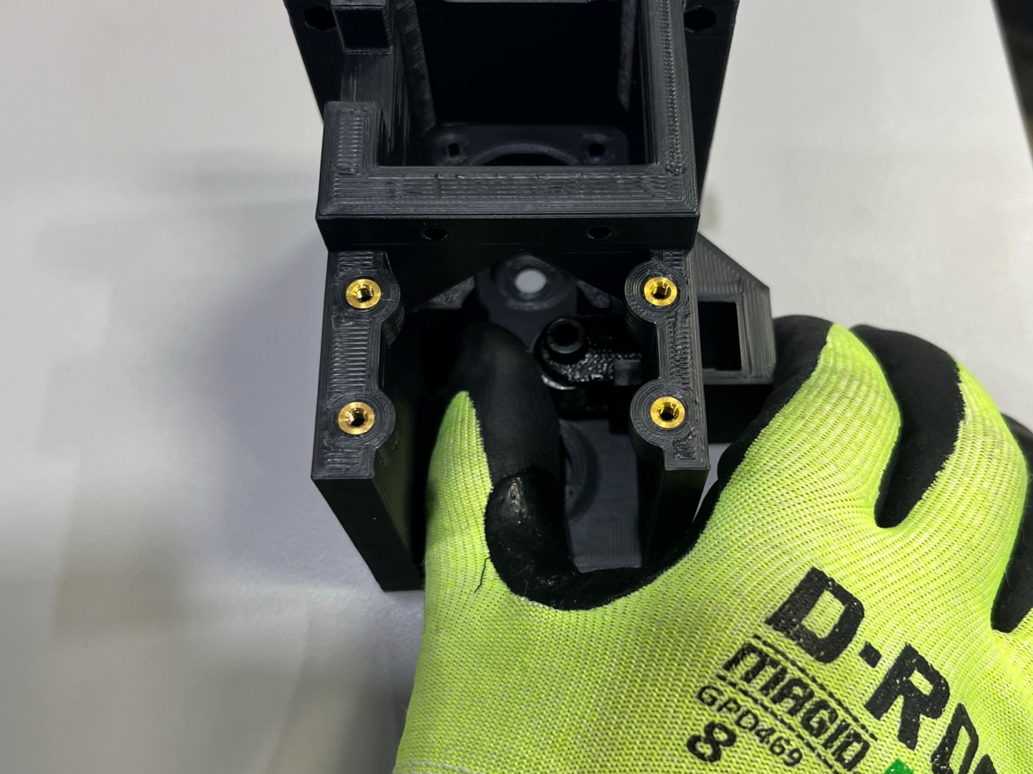
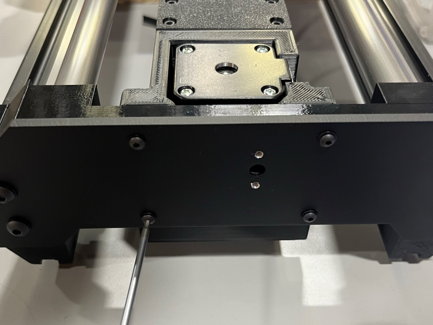
Then slide the tension block inside the bottom right cavity in the 2-1 Y motor mount, make sure the bolt head is facing up.
Now place 2x M3 locknuts inside the nut traps in the 2-1 Y motor mount, make sure the nylon ring is on the outside.
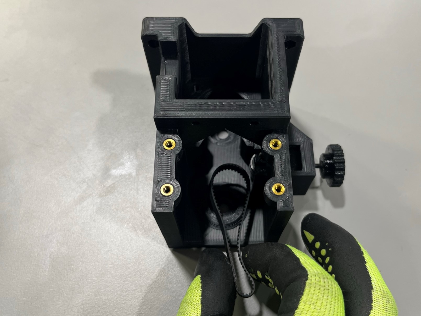
Take the GT2 rubber timing belt and slide it into the 2-1 Y motor mount, make sure its surrounding the circle in the back half of the motor mount.
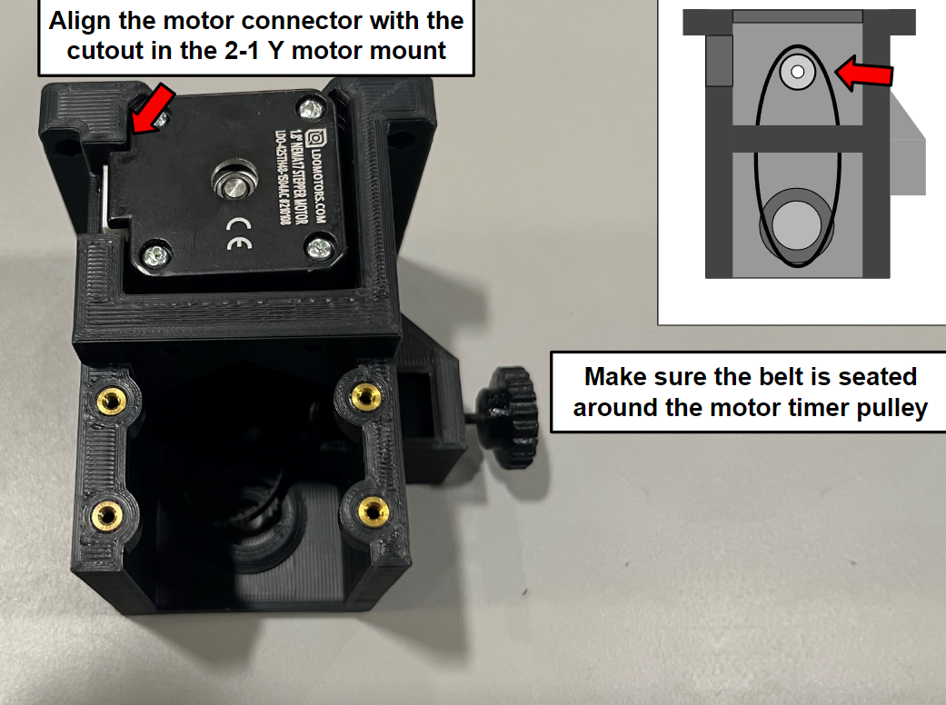
Then align the motor the with 2-1 Y motor mount, make sure the rubber timing belt goes around the motor timing pulley and that the motor connector port is aligned with the cutout in the motor mount.
Now wrap the other end of the belt around the 40T timing pulley that's on the rotary shaft and press the bearing into the front circle hole in the 2-1 Y motor mount.
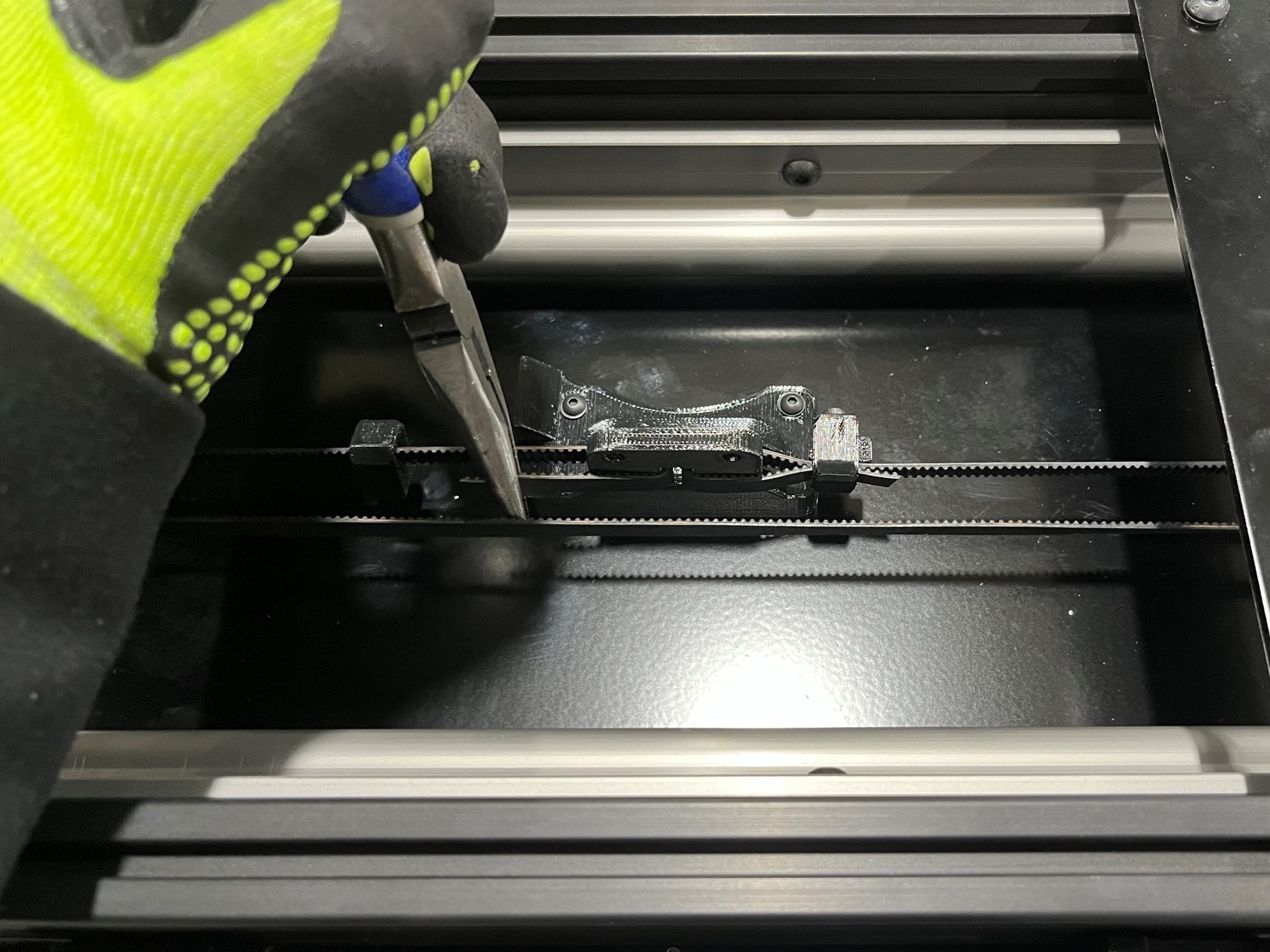
Now take the single sided open loop belt [HD-BL0037] and wrap it around the top timing pulley.
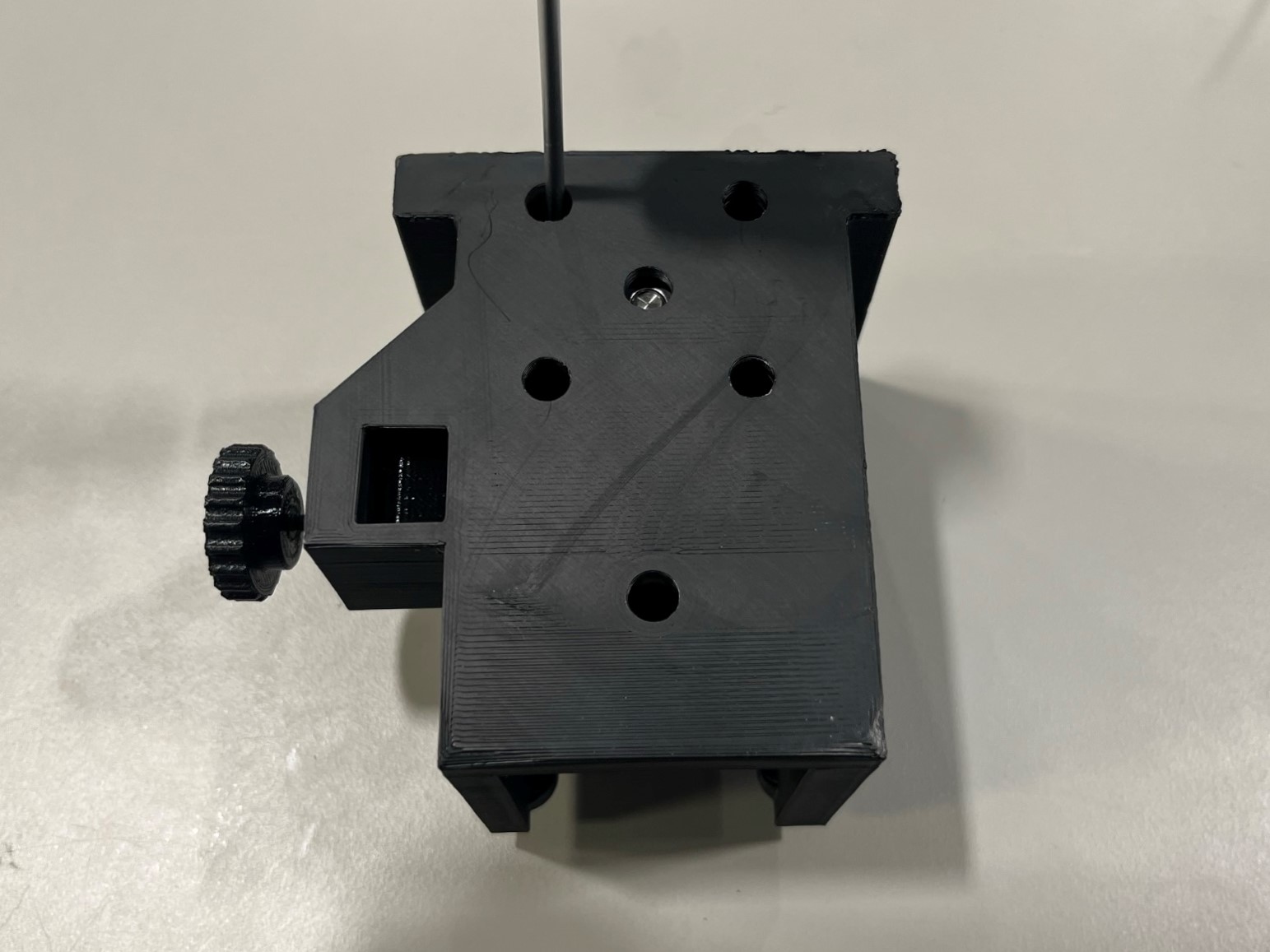
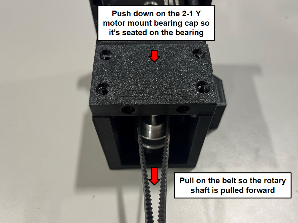
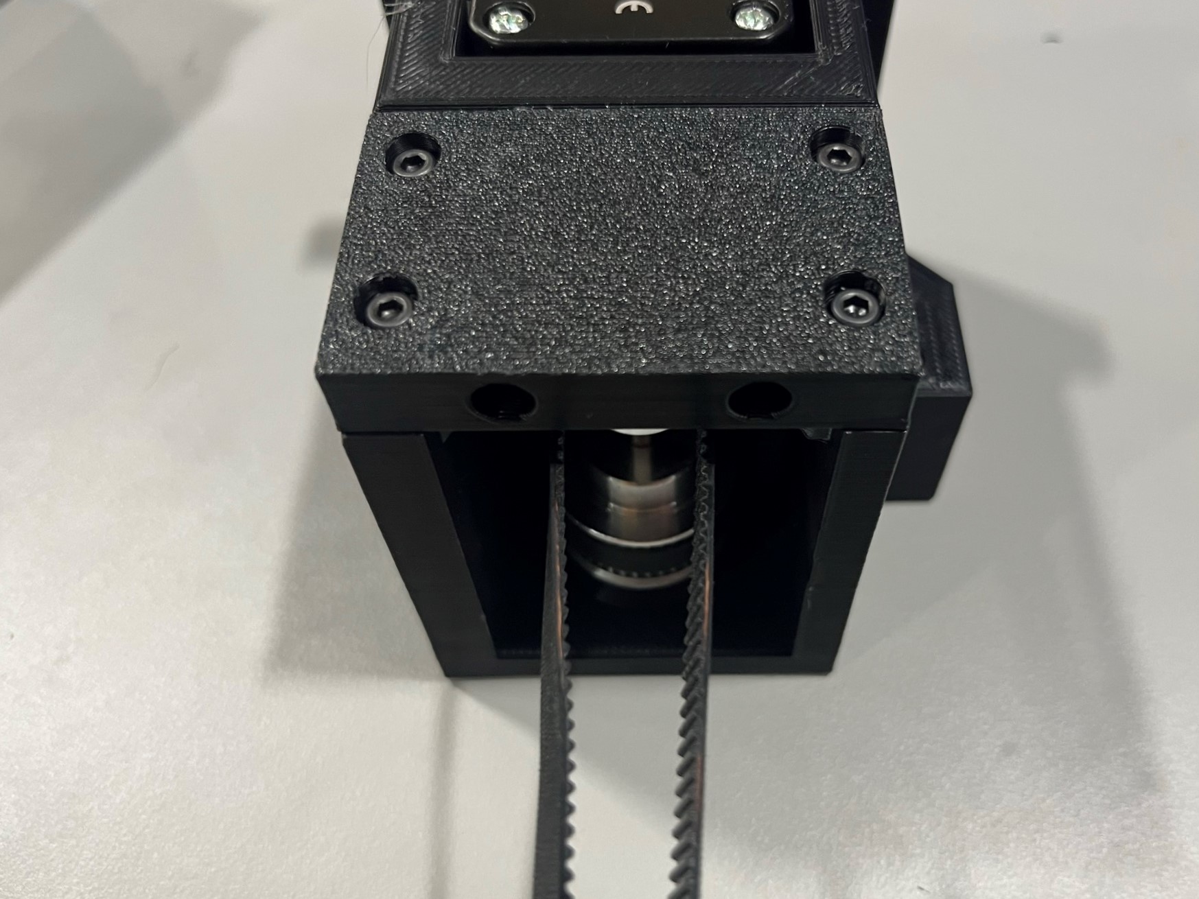
Once the rotary shaft is seated inside the motor mount place the 2-1 Y motor mount bearing cap [PP-GP0721] over the top bearing. Make sure the side that has the larger holes is facing out. You may have to pull on the open loop belt in order to fix the bearing cap over the top bearing.
Then use 4x M3x12 SHCS [HD-BT0039] to secure the bearing cap to the motor mount.
Now take 2x M3x20 BHCS [HD-BT0171] and thread them into the two lock nuts seated by the motor.
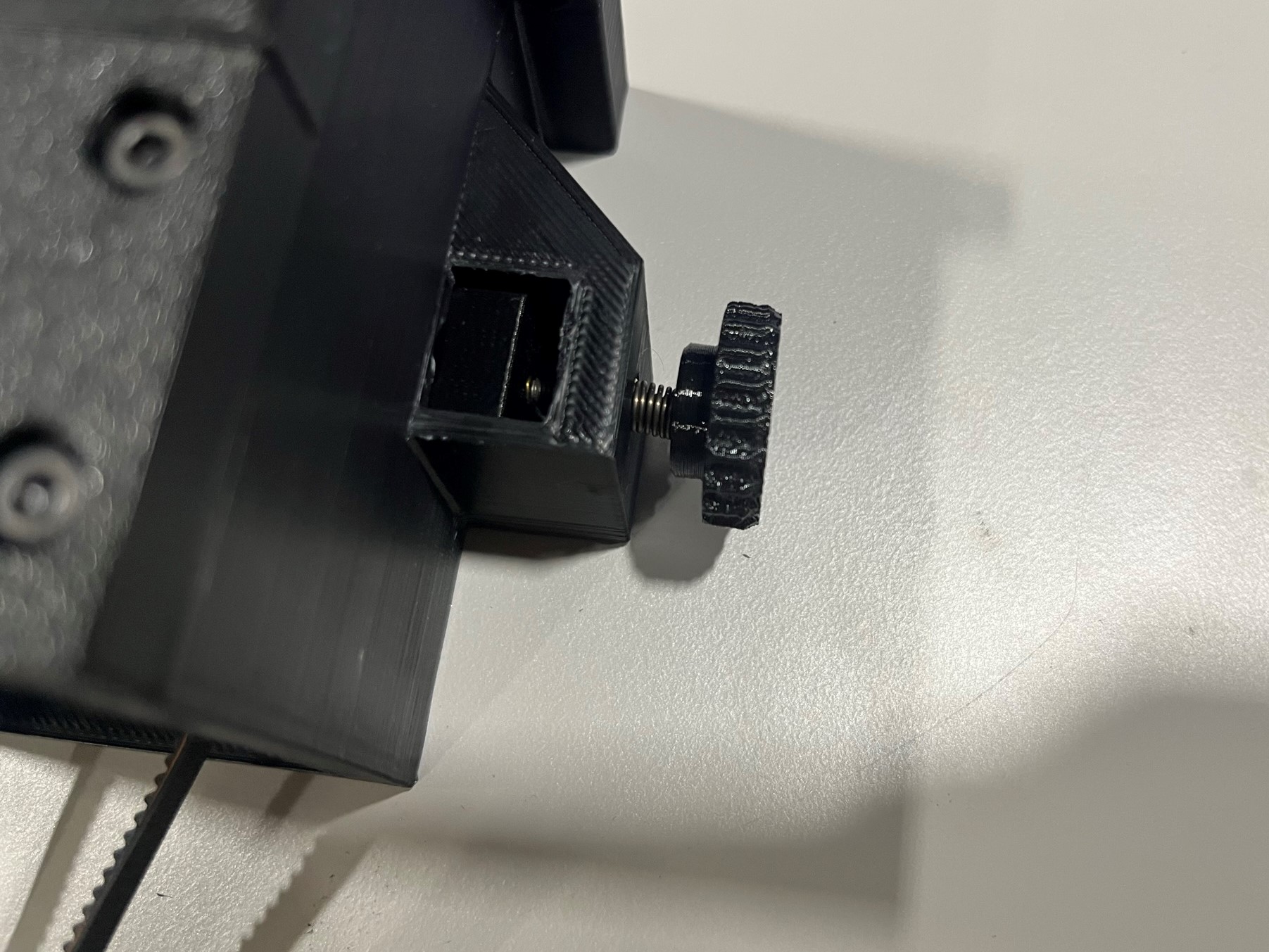
Take the tension knob [PP-GP0724] and slide a compression spring [HD-MS0471] around the bolt.
Now thread the bolt into the insert on the side of the motor mount.

Use 4x M3 locknuts [HD-NT0001] and place one in each nut trap on the sides of the 2-1 Y motor mount. Make sure the nylon ring is facing out!
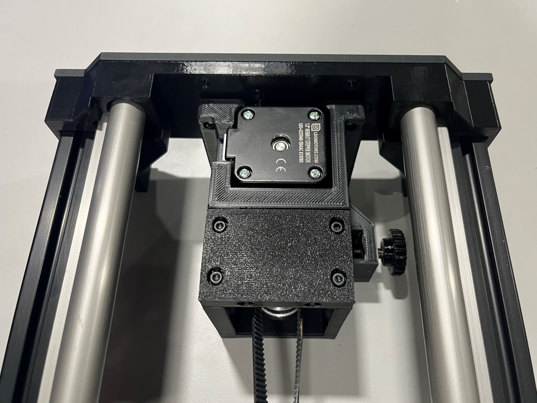
Then place the mount mount inside the long bed frame carefully so that the locknuts stay in place.
Then use 4x M3x20 BHCS [HD-BT0171] with M3 washers [HD-WA0038] to secure the motor gear box to the long bed end plate, try to make the top of the 2-1 Y motor mount level with the combined Y end.
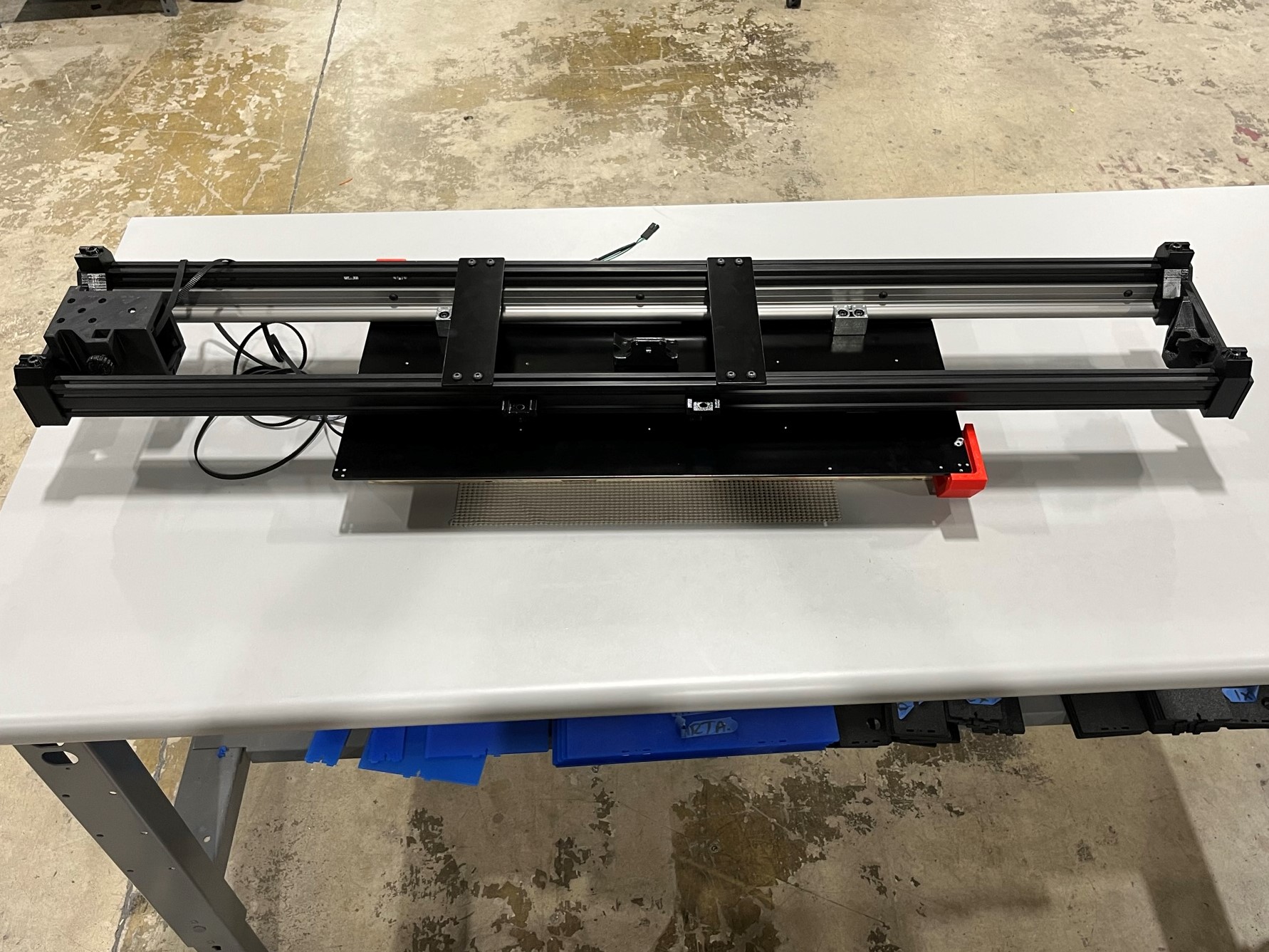
Carefully flip the long bed over so that it's resting on the bed plate.
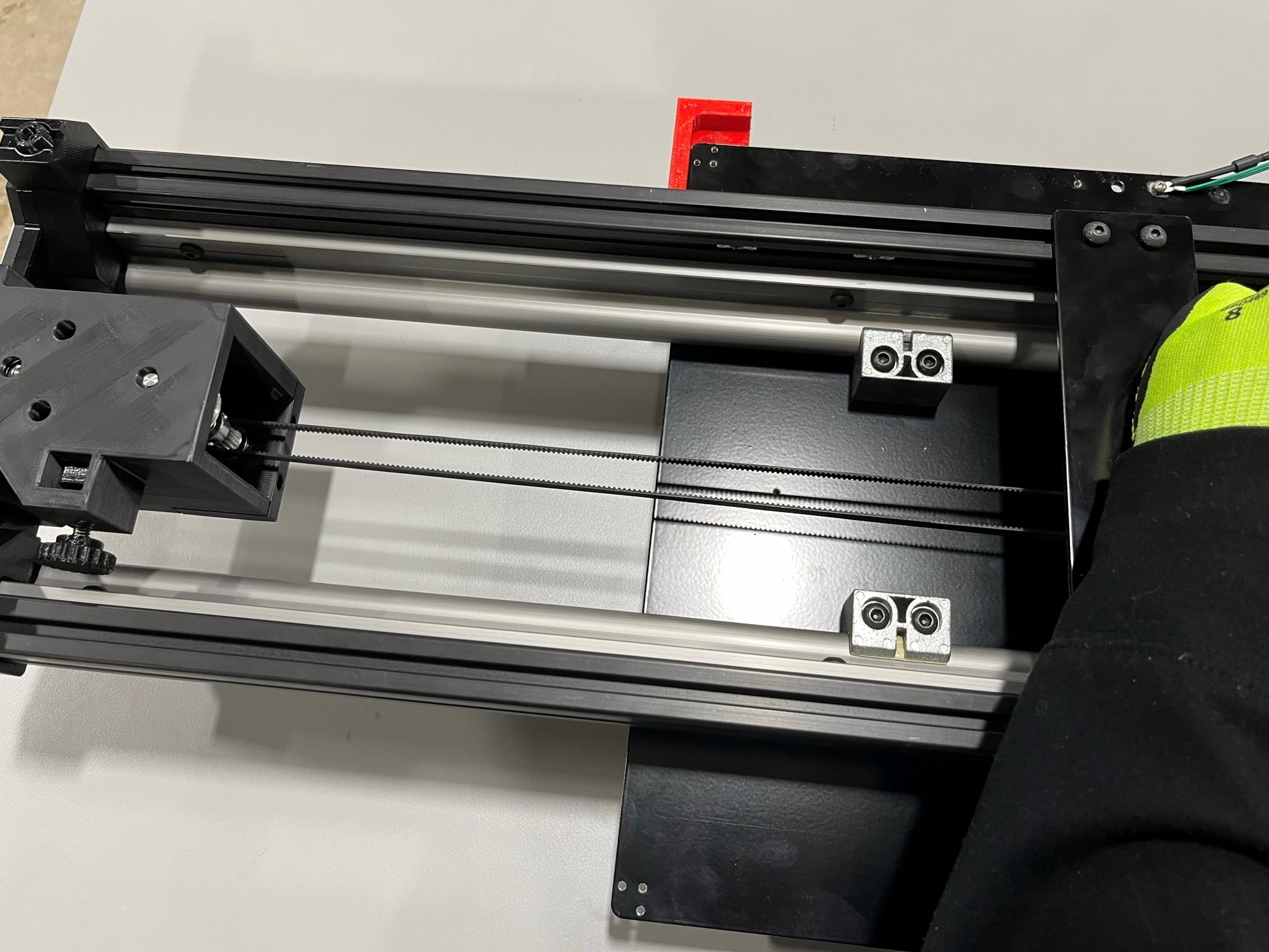
Then take the side of the belt that is on the opposite side of the round cutout in the long bed plate and route it between the bottom supports and the bed plate until its on the idler side of the long bed assembly.
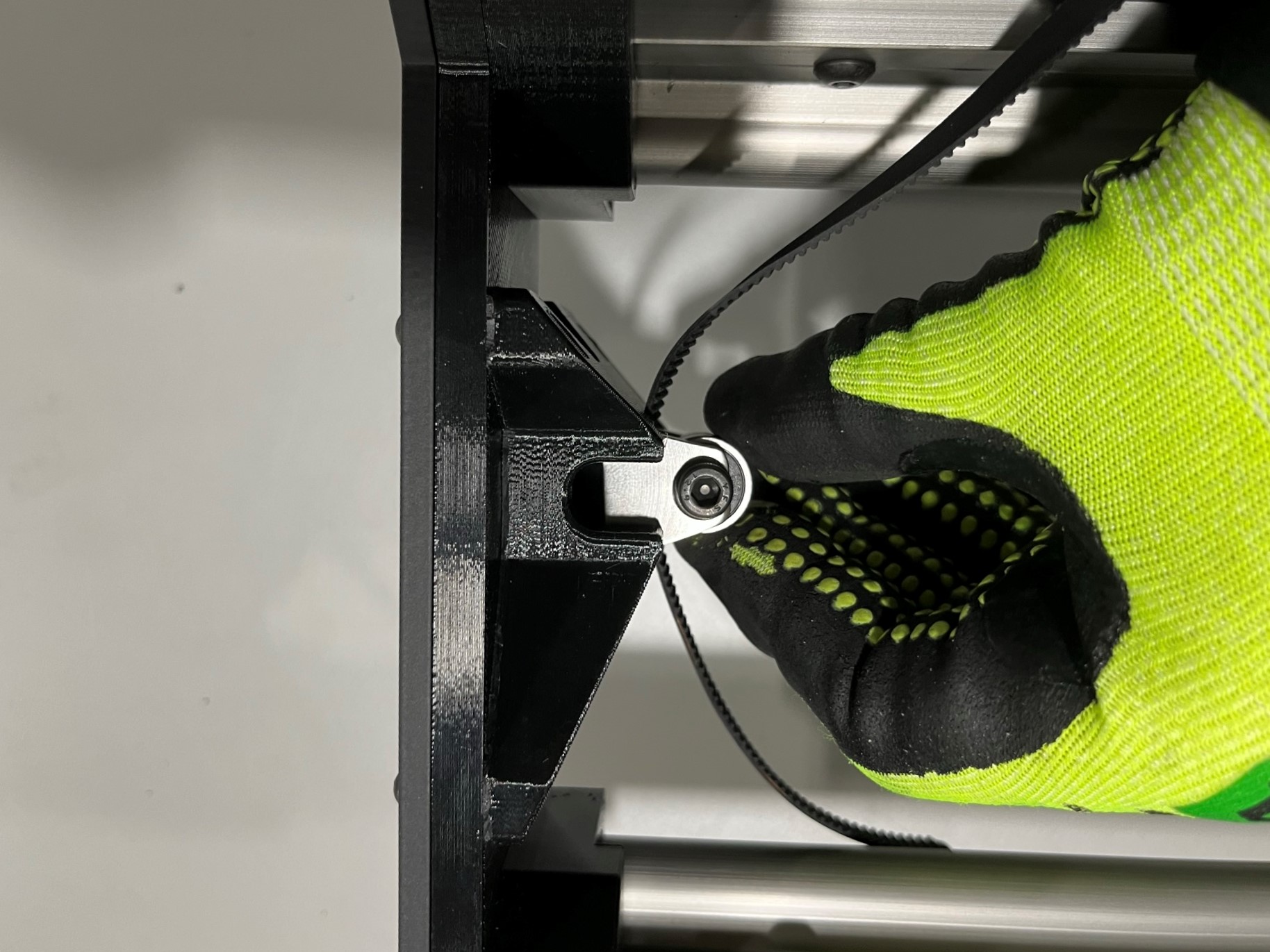
Now assemble the YZ idler using 1x YZ idler [PP-MP0225], 2x rubber sealed bearings [HD-MS0411], 1x M5x20 SHCS [HD-BT0151] and 1x M5 washer [HD-WA0040].
Place the two bearings inside the YZ idler making sure the holes align, then place the washer around M5x20 SHCS and secure the bearing inside the YZ idler. Do not over tighten
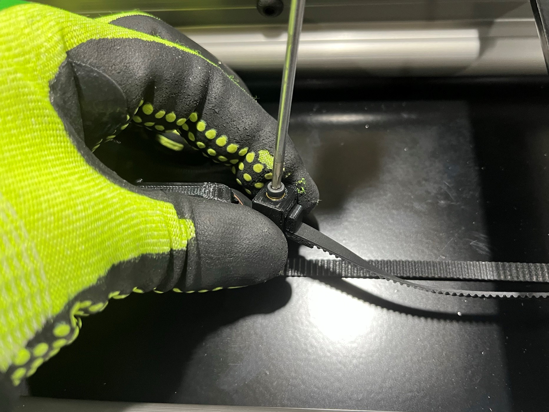
Then place the idler on the table with the head of the screw facing up and the flat side of the YZ idler facing the idler end of the long bed. Now route the belt around the bearings with the teeth facing in as shown in [reference#4].


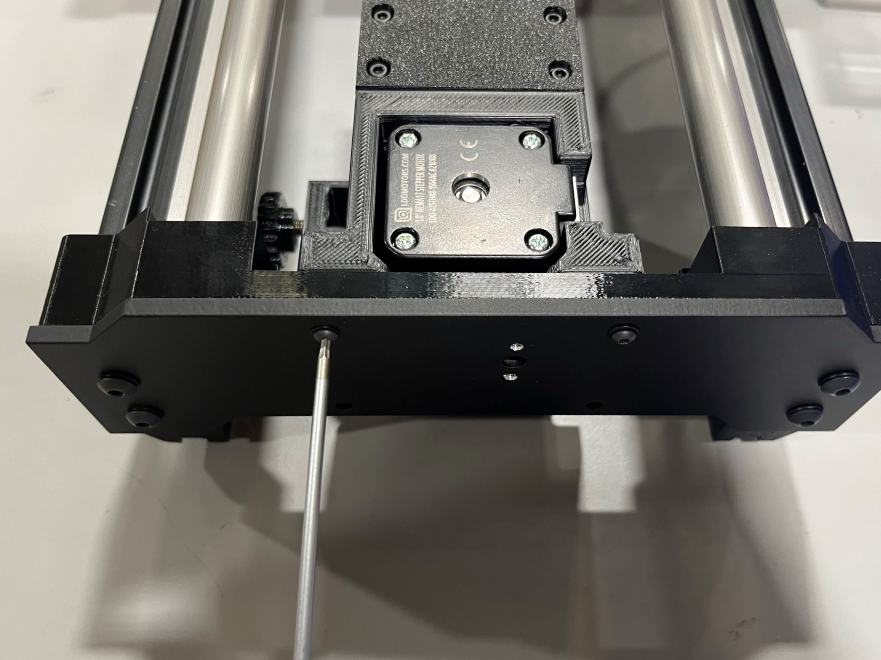
Go to a open table and place two empty bins (same size) side by side with a couple inches between them. Then place a 3mm ball screw driver and a 4mm screw driver by the bins these will be needed for this step.
Then remove the long bed assembly from the extrusion fixture, and place the fixture on top of the bins making sure it is fully supported by the bins.
Then set the long bed in the extrusion fixture. Once the long bed assembly is elevated and resting in the extrusion fixture make sure not to leave the table, this is to prevent the long bed from falling.
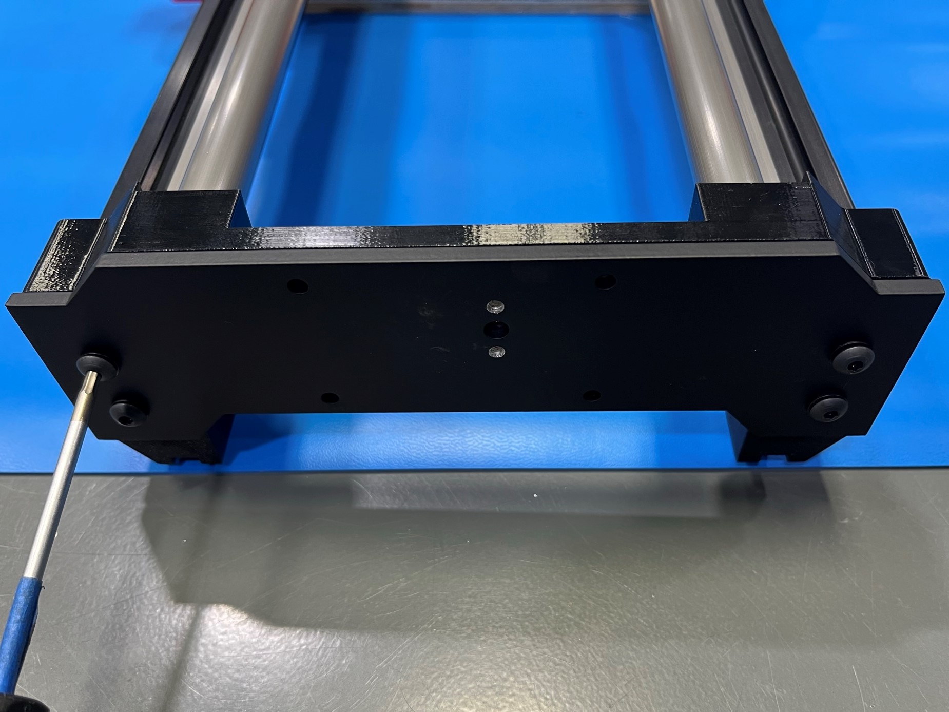
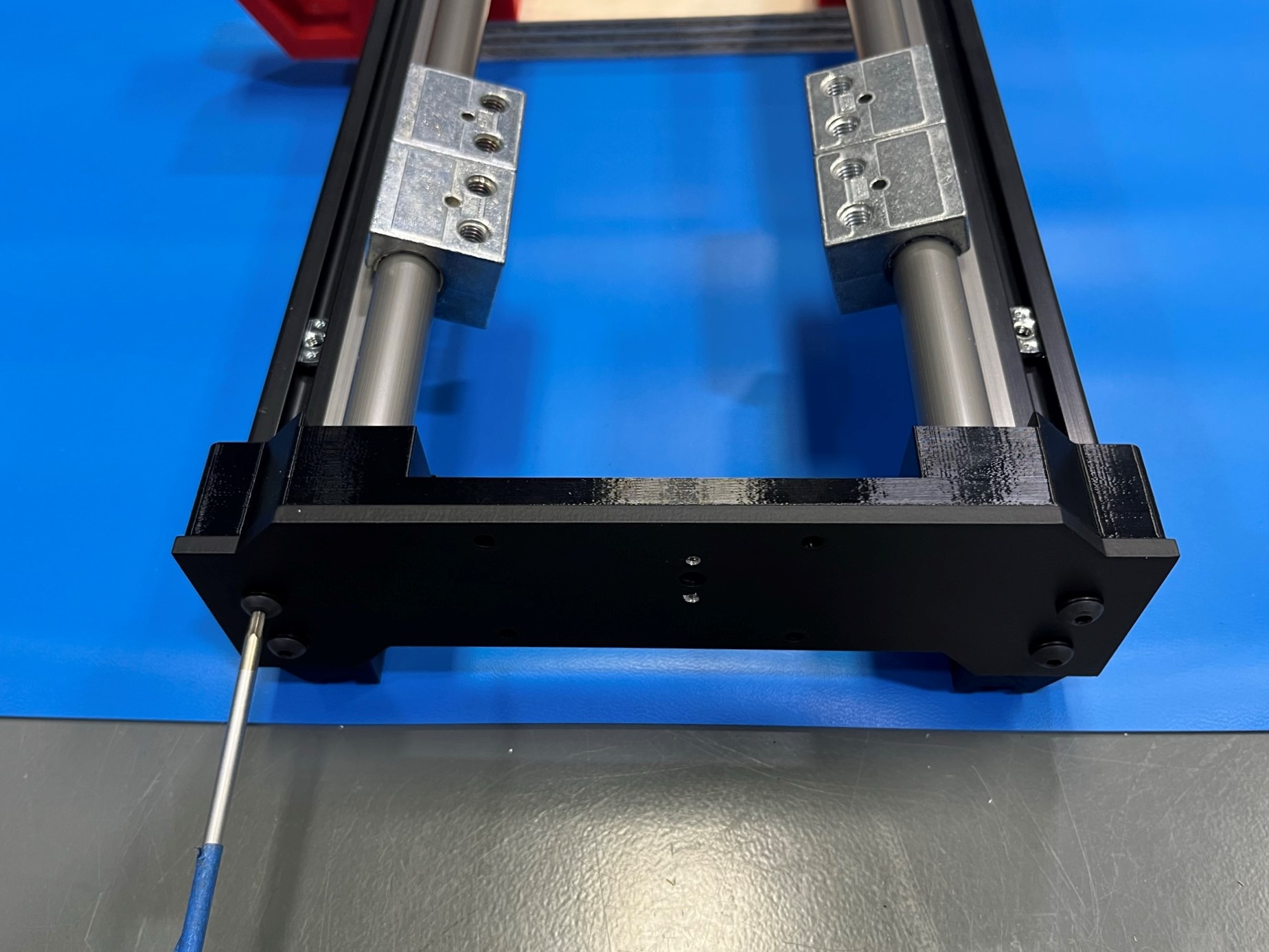
Tighten all ten bolts that are holding the linear rail to the extrusions. Use will have to use the 3mm ball screw driver or a 3mm hex key since there isn't enough room for a regular 3mm screw driver.
Now slide the bed plate to either end and tighten the drylin bushings that are on the same side as the cutout in the bed plate. Make sure to only tighten one bushing at a time.
Then slide the bed plate to the other end of the linear rails and repeat for the second bushing.