Open HardwareAssembly Instructions
Guides for installation and assembly of the LulzBot line of products made by FAME 3D LLC.
Guides for installation and assembly of the LulzBot line of products made by FAME 3D LLC.
The Nextech DFS 100 N Force Gauge has a maximum capacity of 100 Newtons.
Exercise extreme caution whenever operating the force gauge, not to overload the load cell.
The load cell is sensitive to motion in all directions; pulling, pushing, twisting, and tilting.
Do not tilt or bend the rod, this can damage the load cell and break the gauge.
Do not over-tighten when installing test rods, this can damage the load cell and break the gauge. FINGER TIGHT ONLY
Do not apply pulling or pushing forces near the 100 Newton capacity.
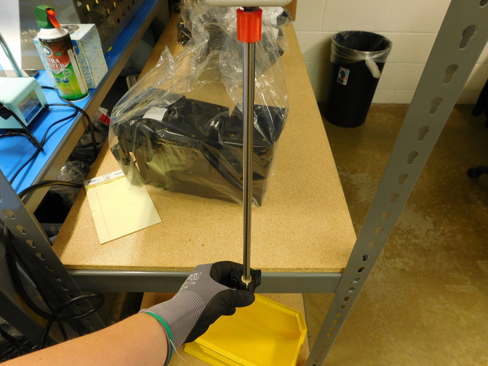
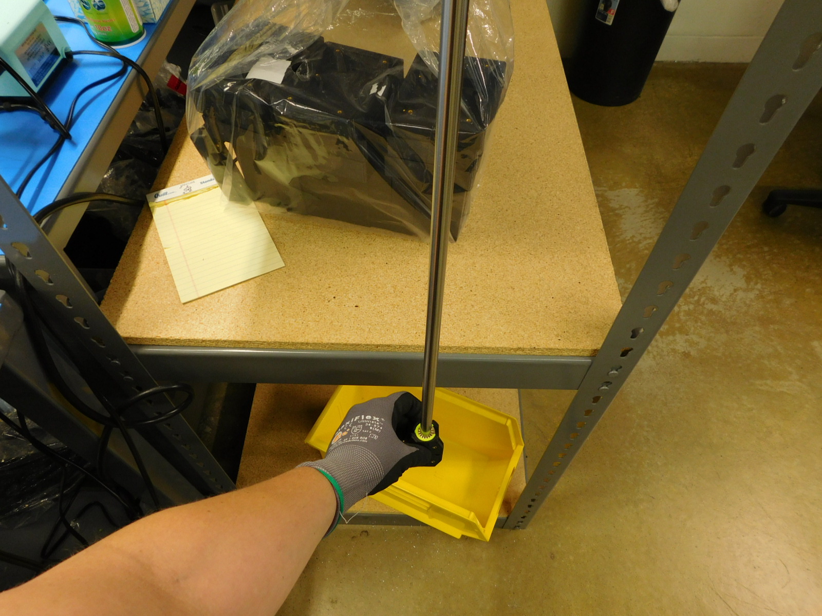
Always remove the test rod and place it back on the shelf when finished testing, this will prevent the possibility of lateral impact to the test rod, which will damage the load cell
Be careful with test rods not to bend or scratch them, this will interfere with proper measurements. Use the provided cushions when storing the test rods on the shelf.
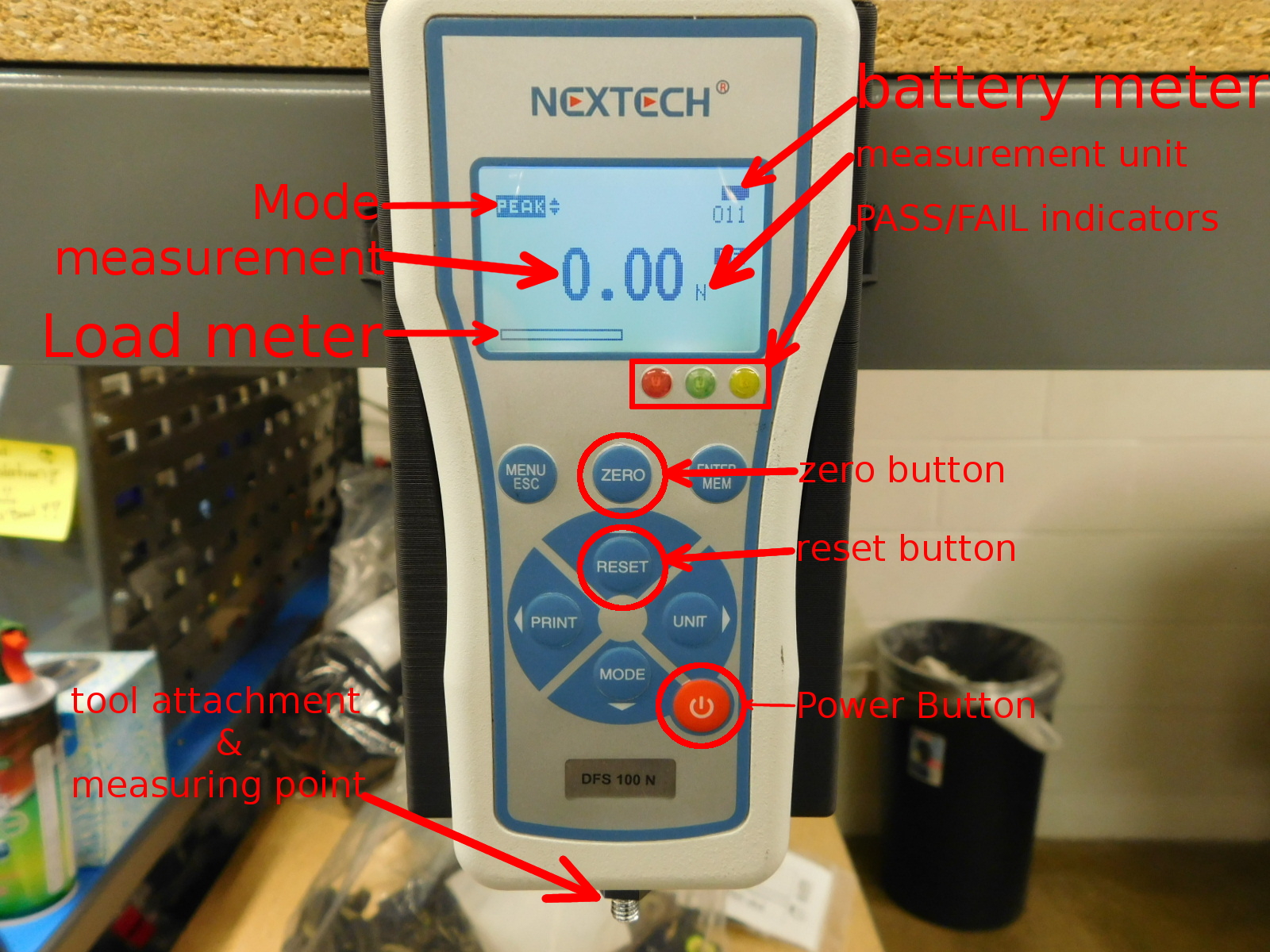
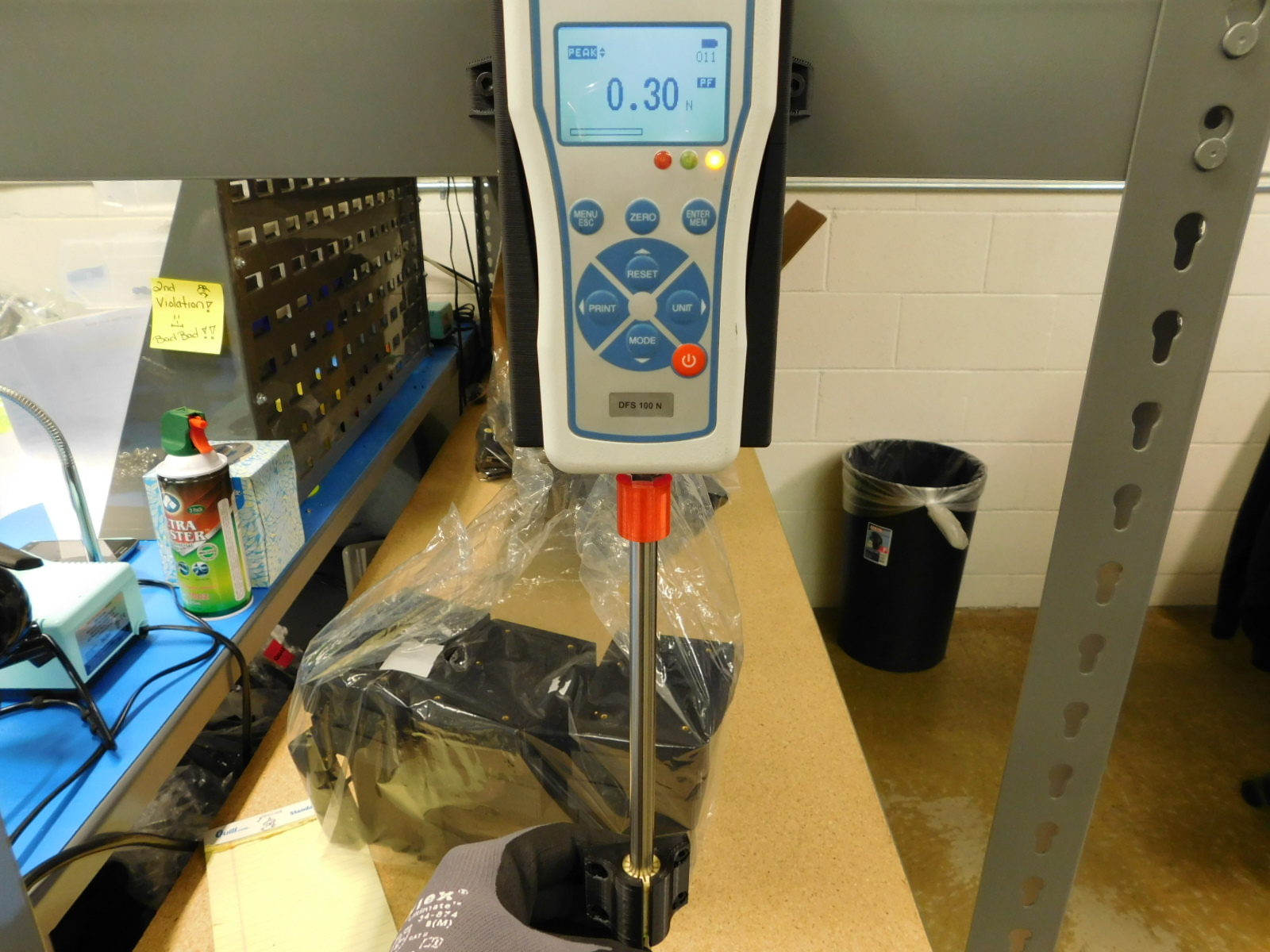
Mode - displays the mode the force gauge is currently in. Should read as pictured, indicating peak pull force
Measurement - where the measured force value is displayed
Load meter - bar for visualization of utilization of the force gauge's capacity, do not allow to reach the limit
Tool attachment & measuring point - directly attached to the internal load cell, this is where tools are attached and where measurements are taken
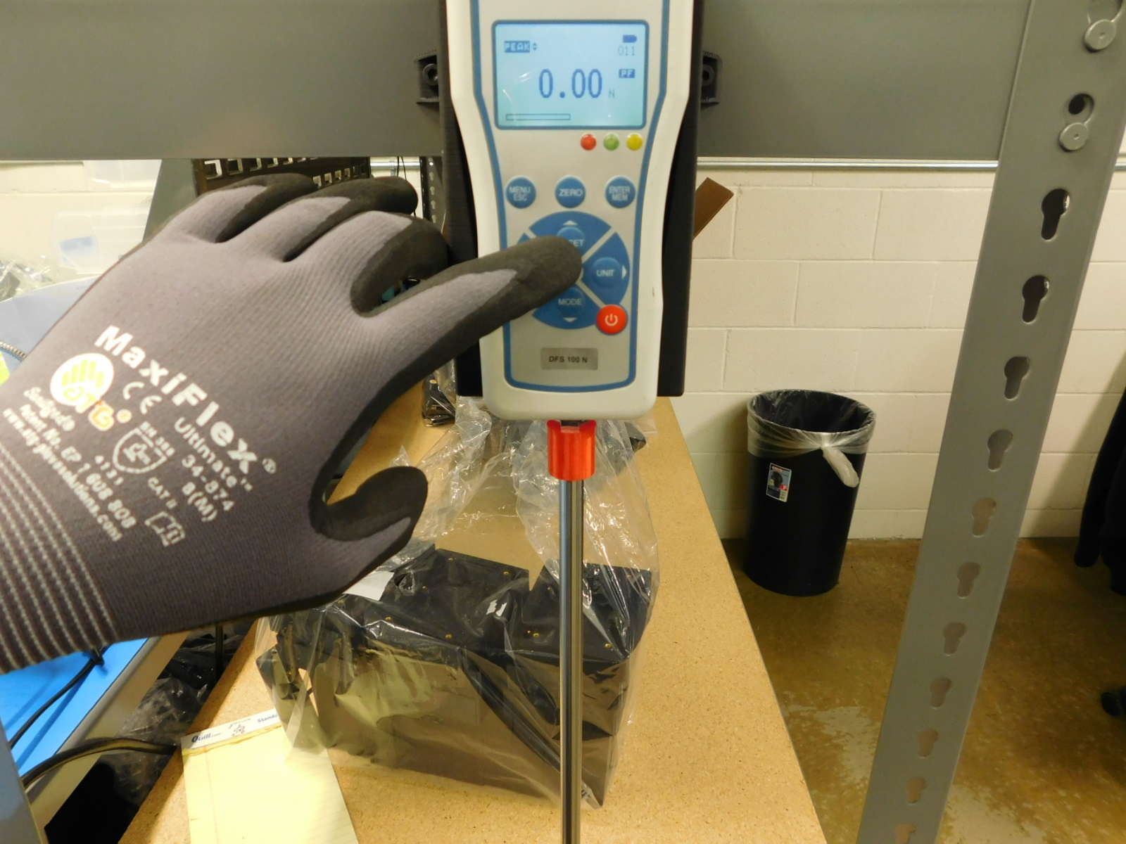
Power button - turns the gauge on or off
reset button - resets the measured value to the zeroed value, performed prior to each test
zero button - tares the weight of the tool and the part being measured
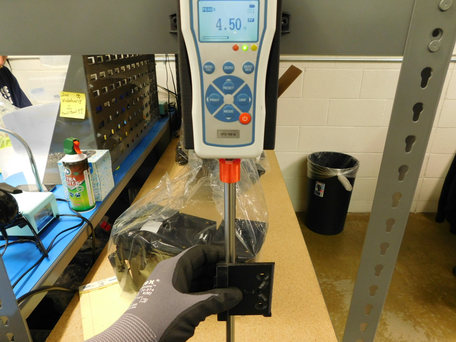
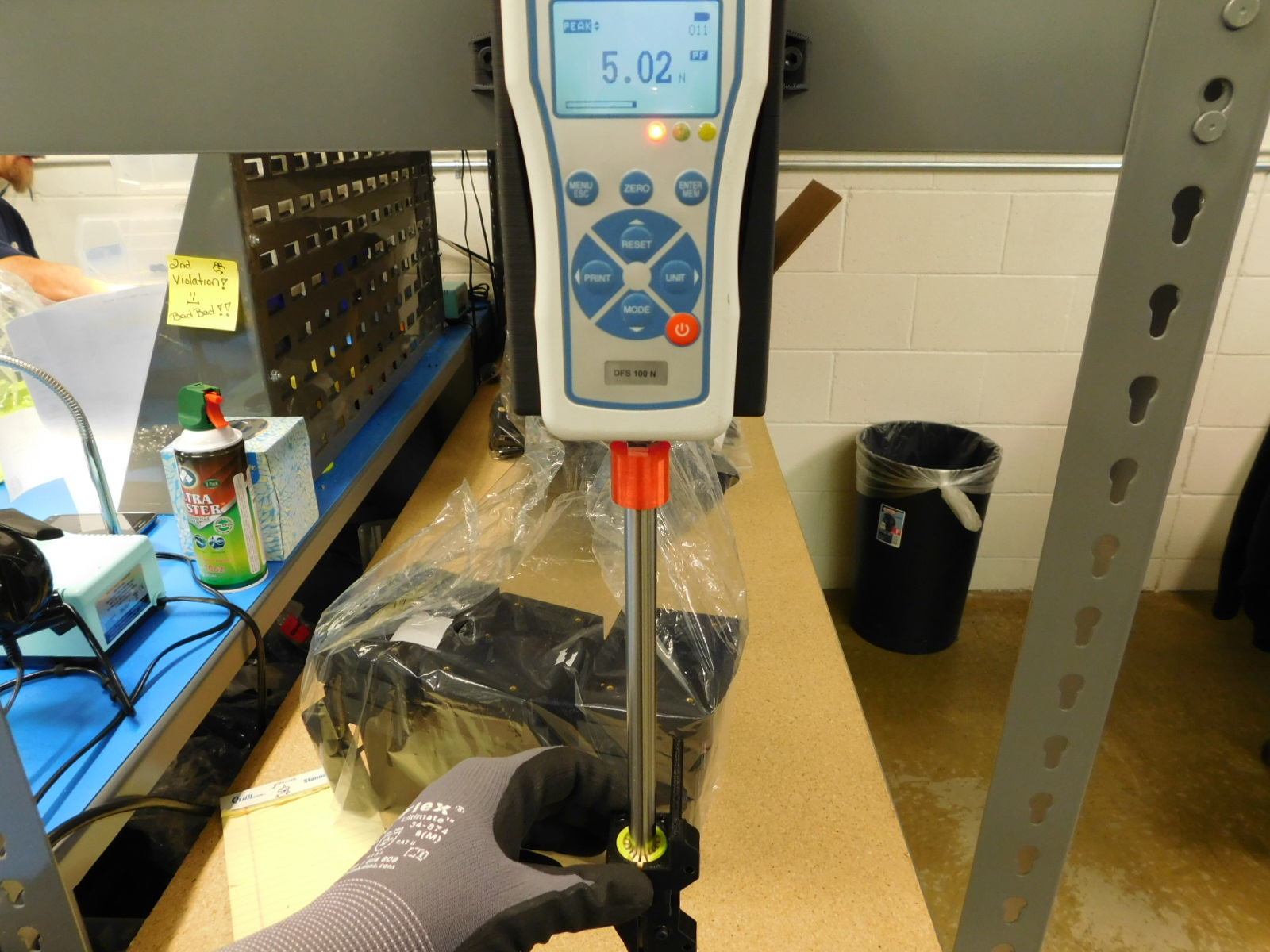
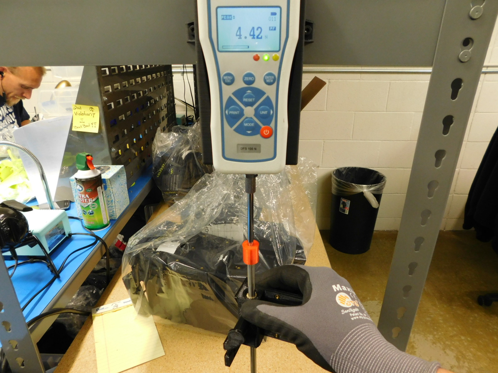
PASS/FAIL indicators - green = good, red = bad, yellow = minimum not met
measurement unit - displays the unit in which the measurement is displayed, we use Newtons (N)
battery meter - indicates how much battery capacity remains
Drag specifications for 10mm double bushings:
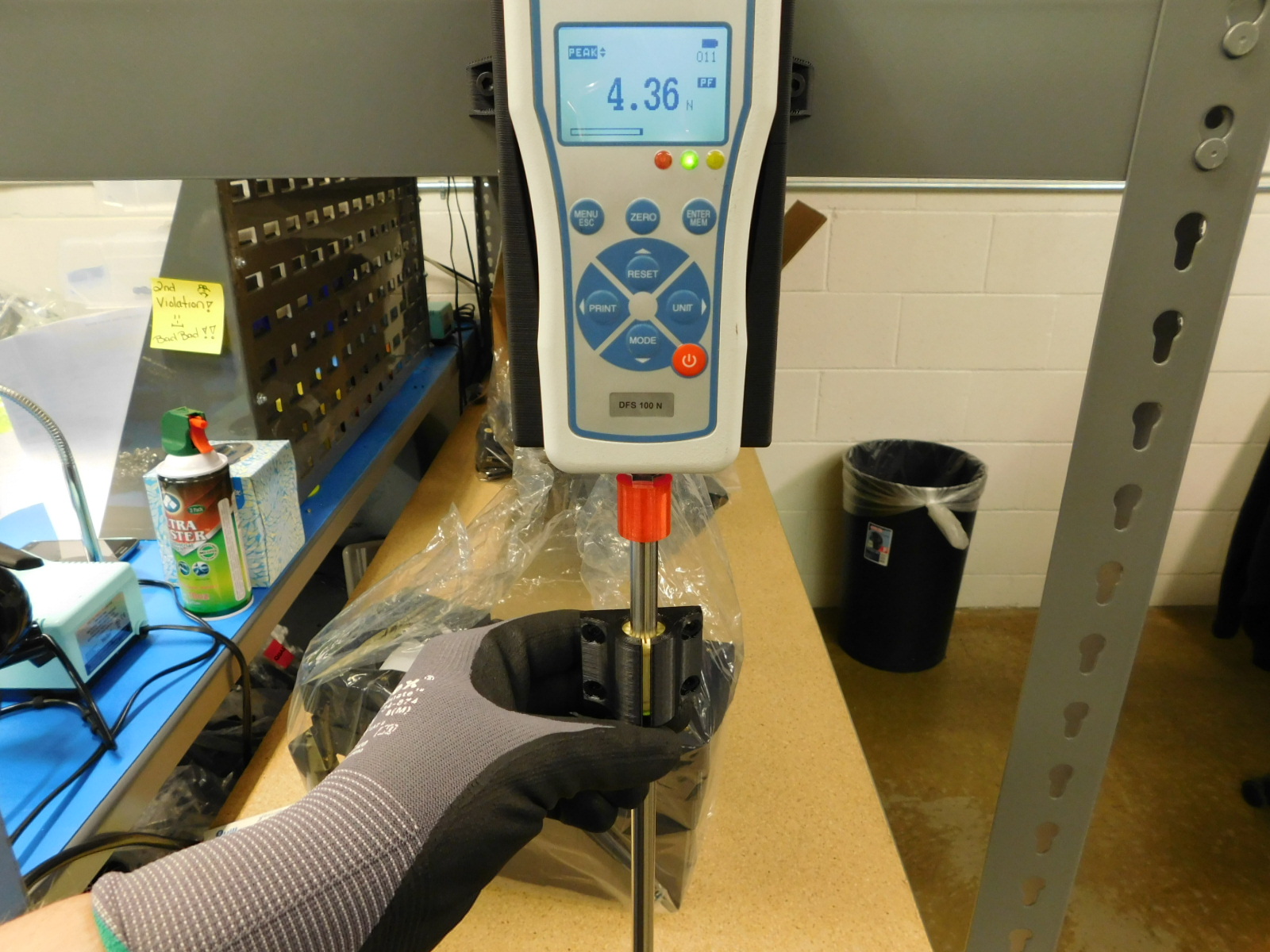
Max allowed drag force: 5N
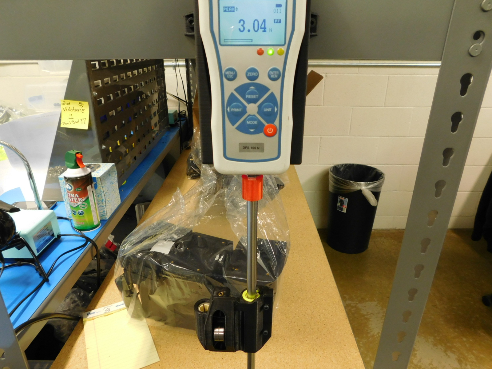
Minimum drag force: 3N
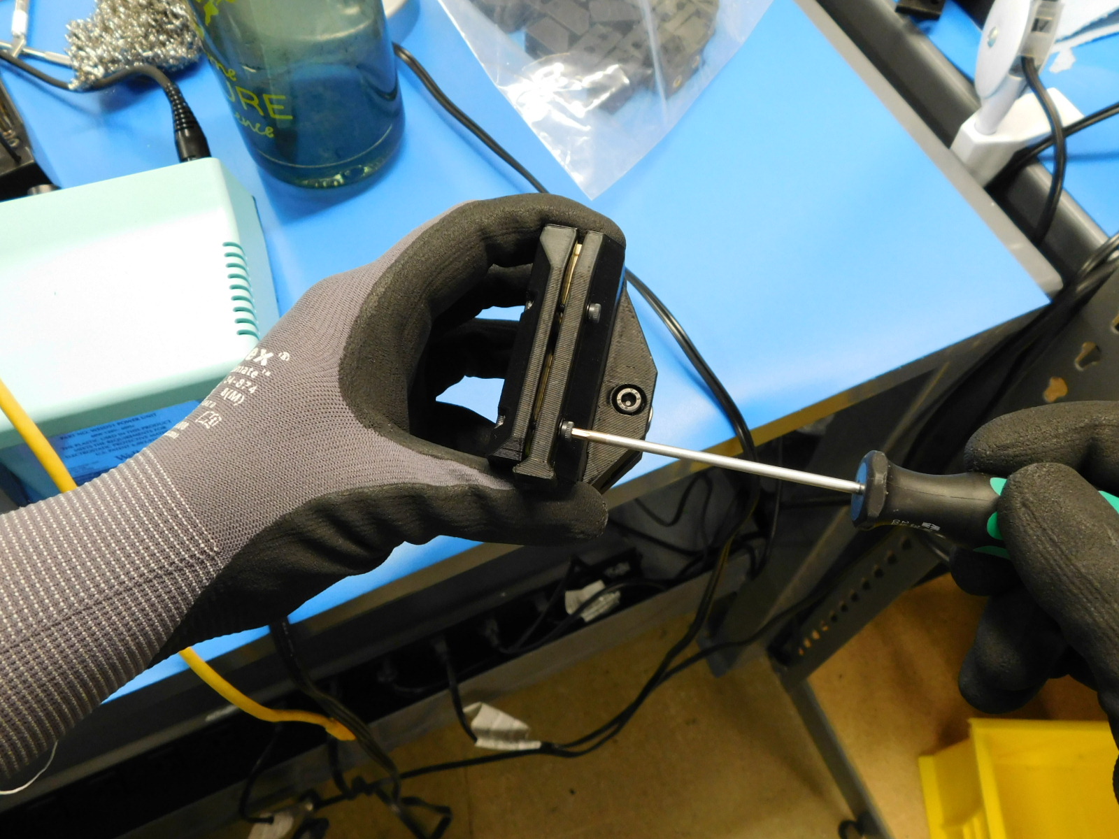
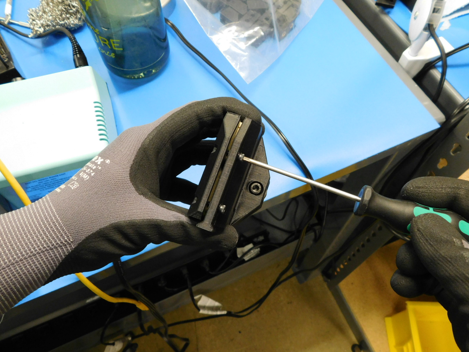
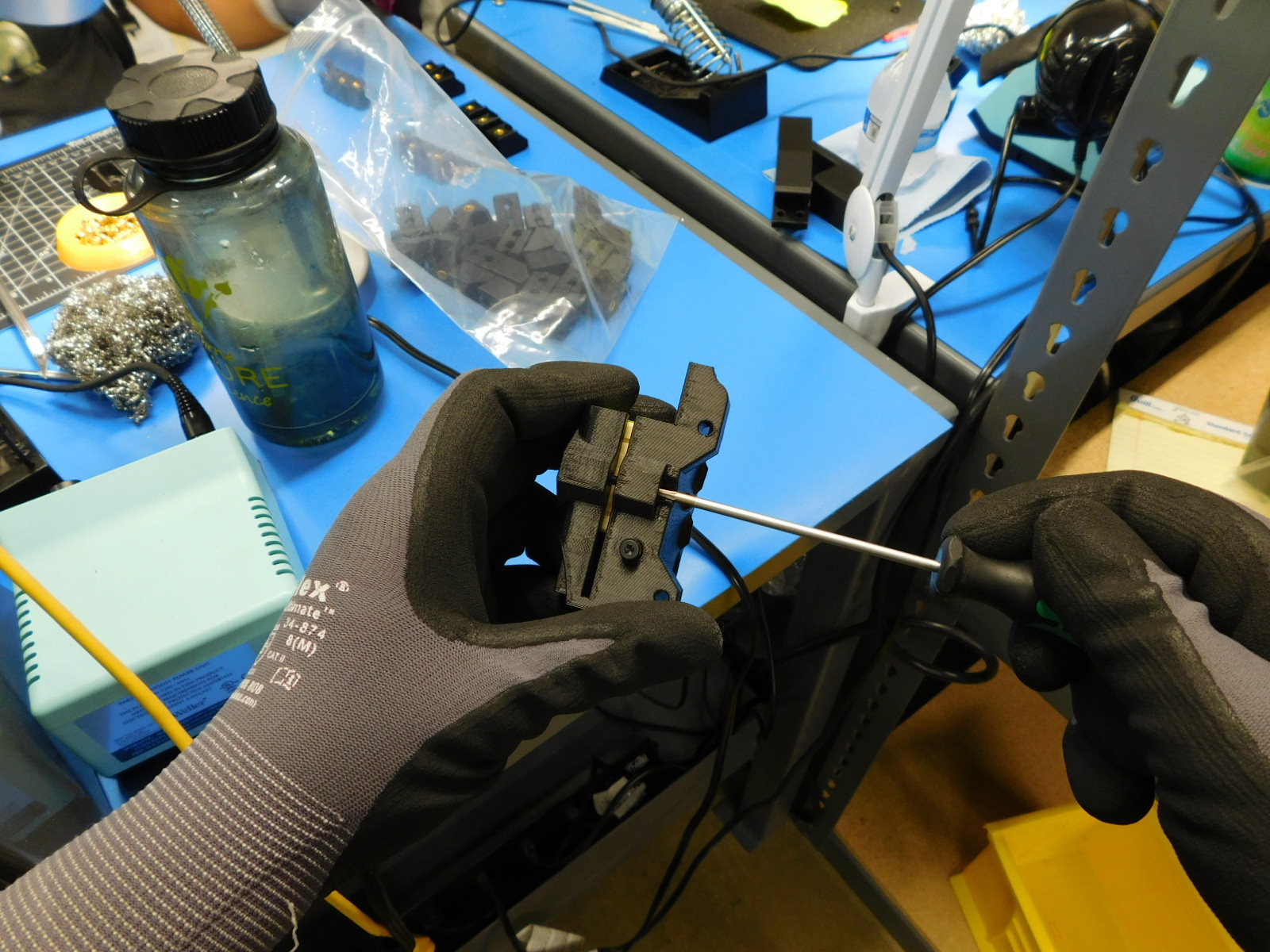
To set 10mm double bushing sets to the correct drag force, begin by tightening both compression screws in even increments until the plastic tabs begin to compress towards the bushings.
Check the drag force using the force gauge:
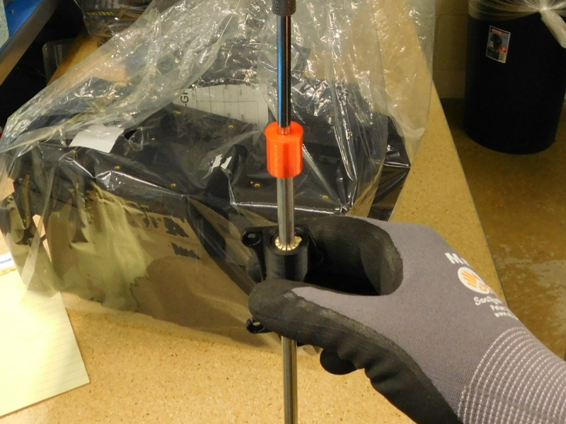
Ensure the 10mm test rod is installed on the force gauge DO NOT OVERTIGHTEN; FINGER TIGHT ONLY
Turn on the force gauge by pressing the power button
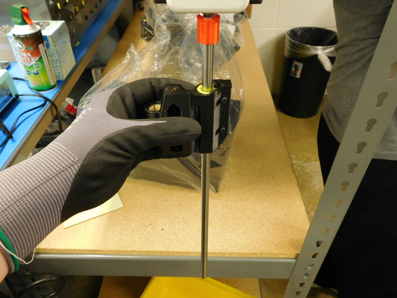
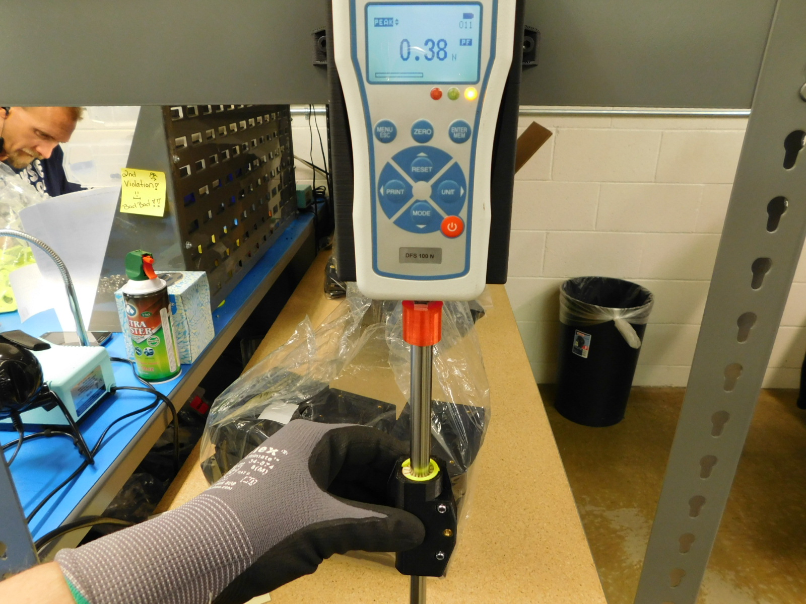
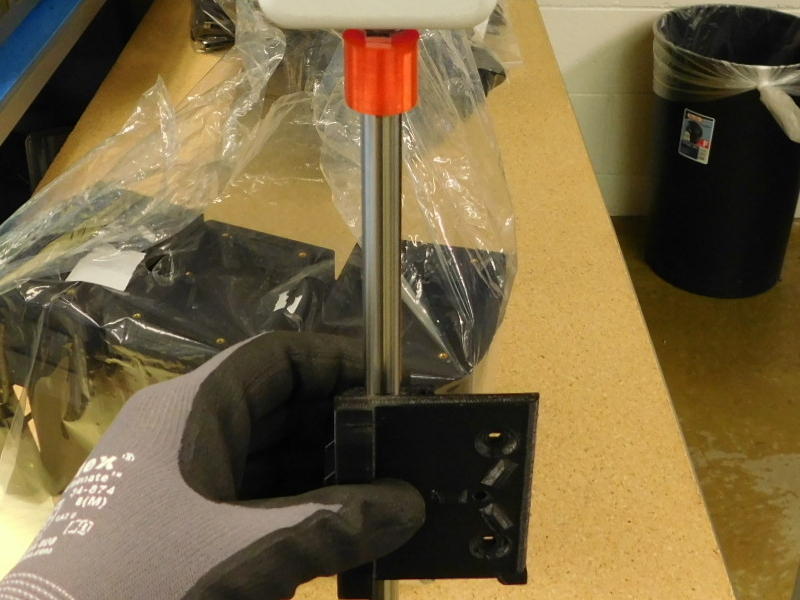
Slide the bushing set to be checked onto the test rod
Press the zero button and then the reset button
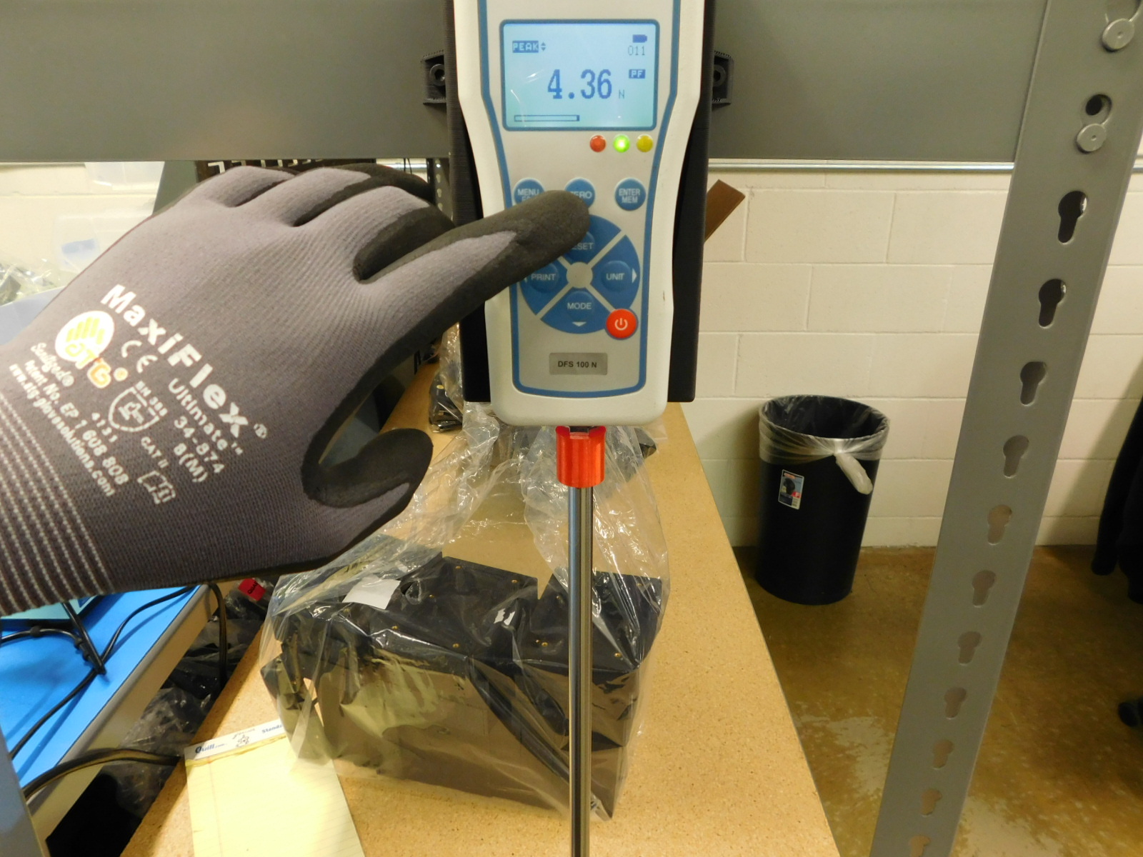
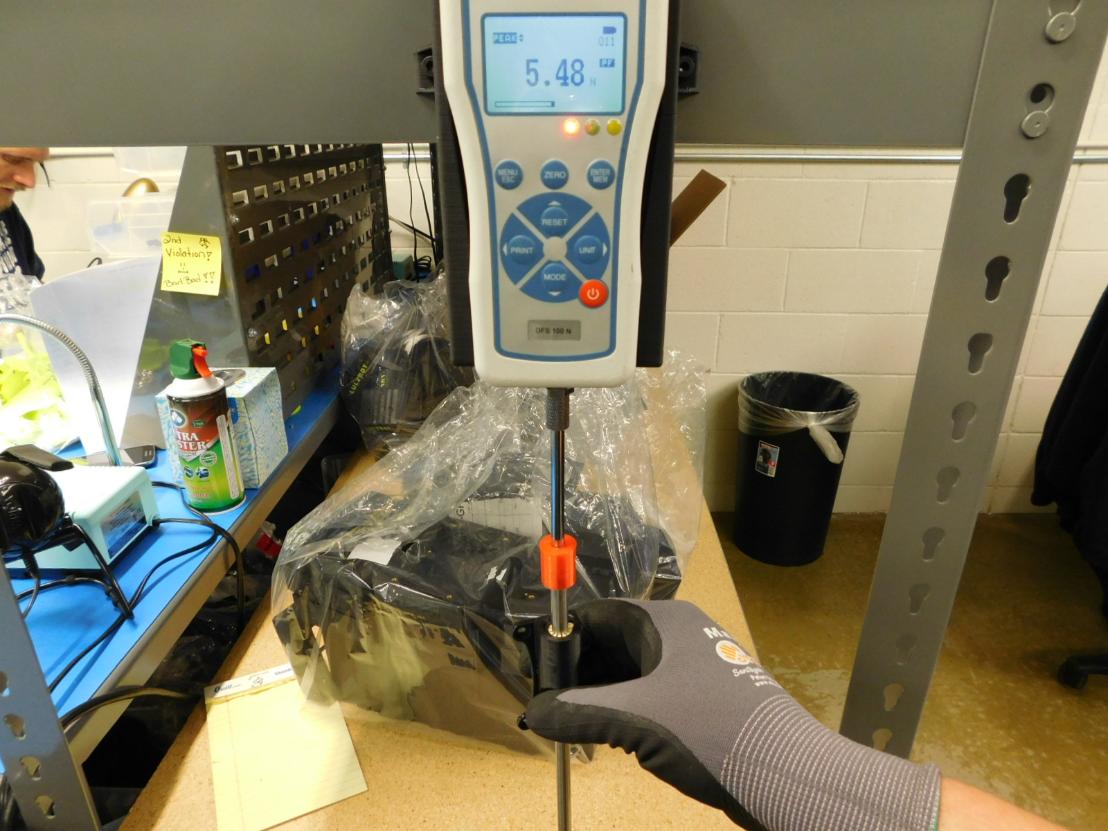
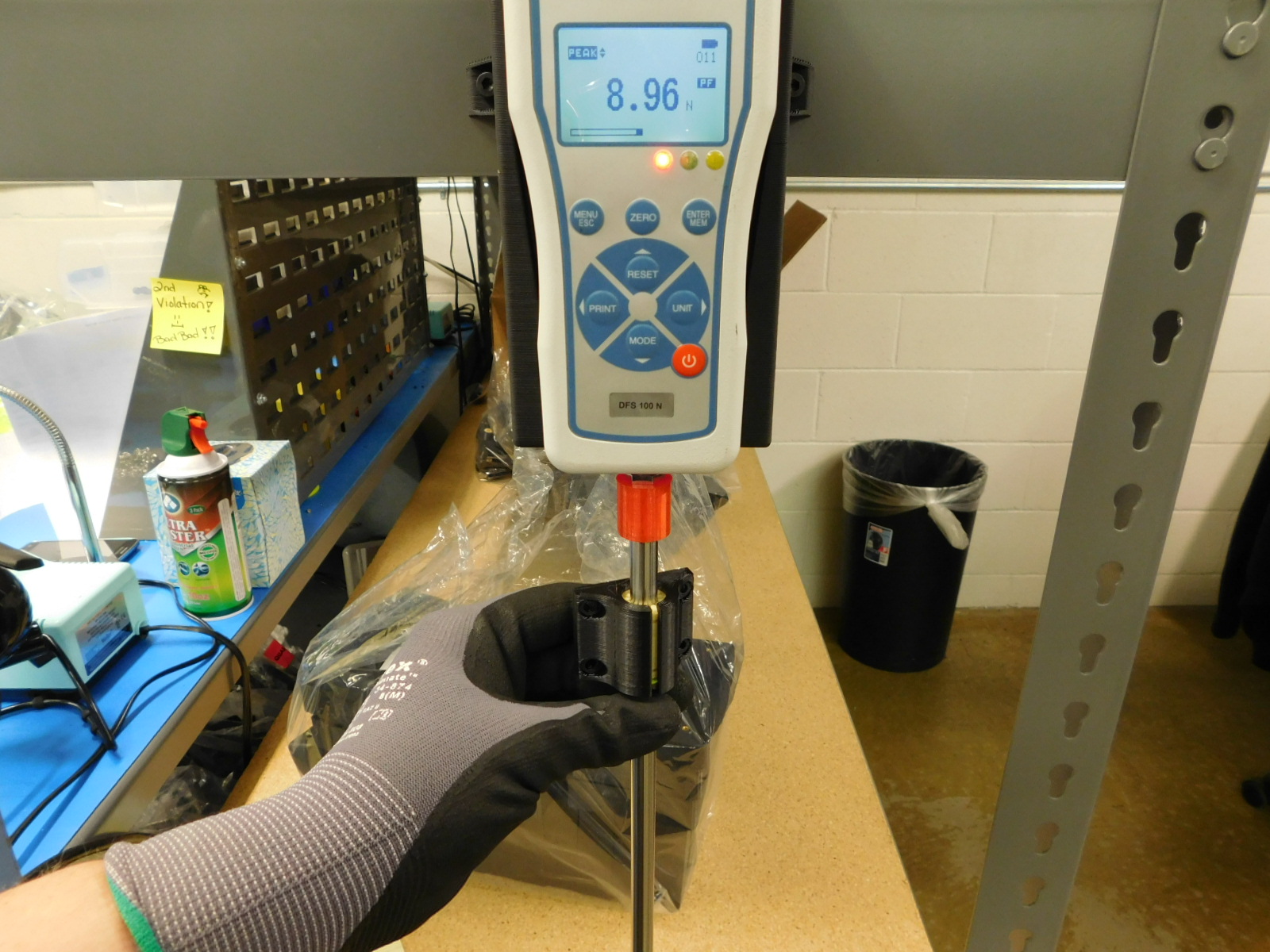
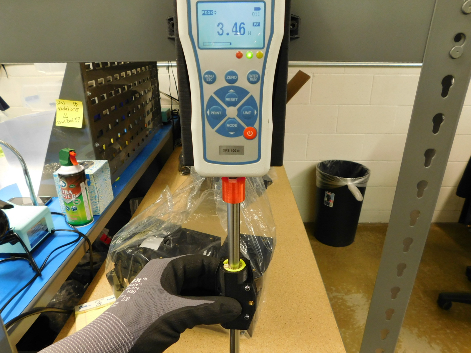
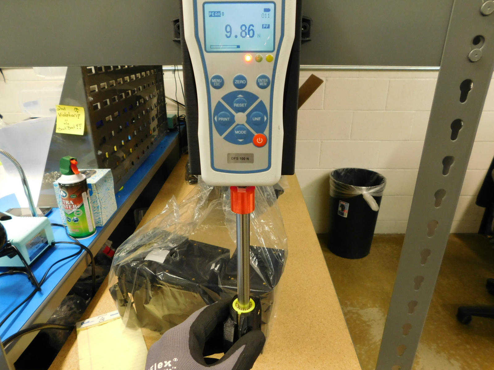
Pull the bushing set downward on the rod
To repeat the test, slide the part back up and press the reset button again
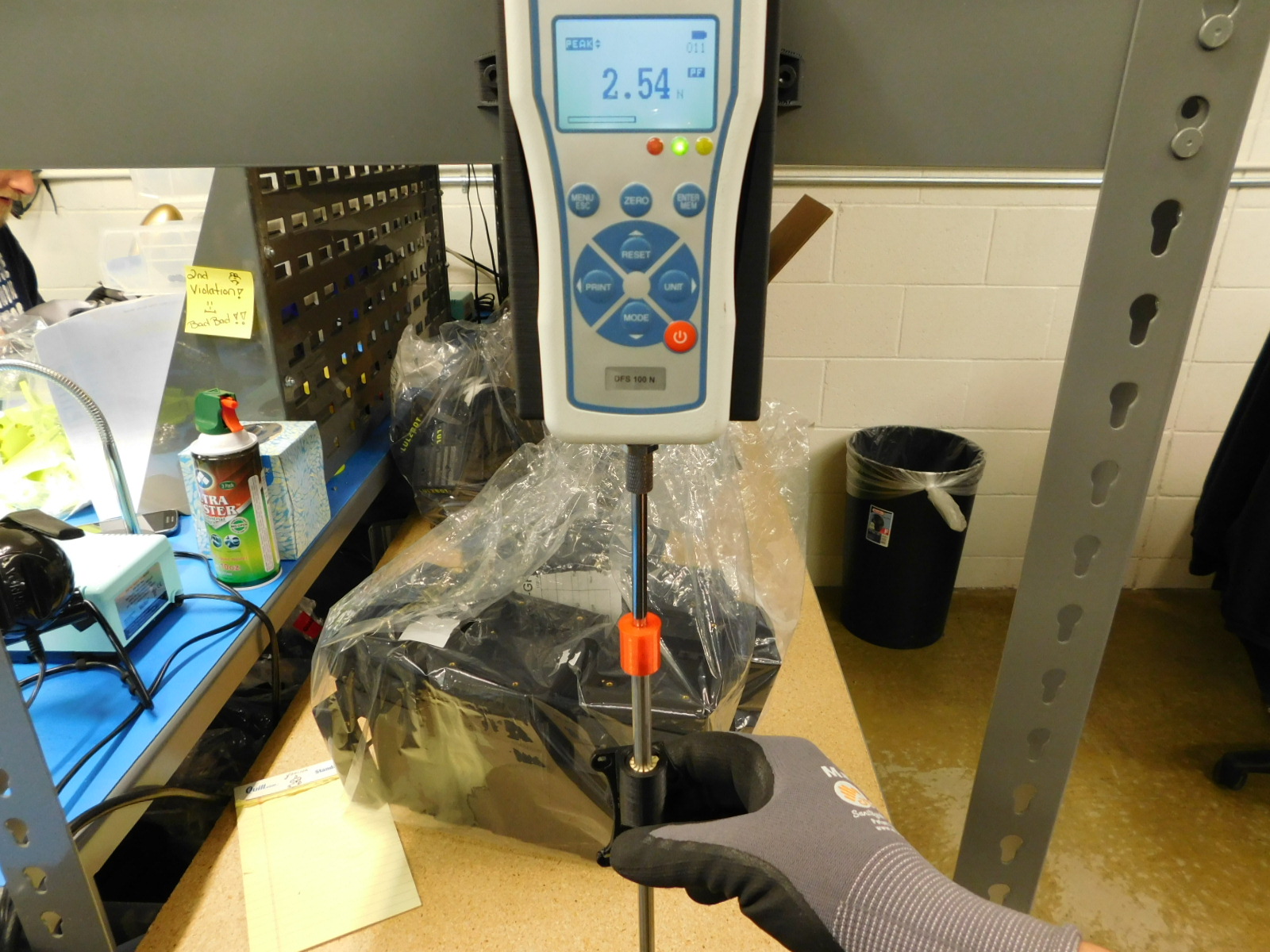
If the GREEN light turns on, the bushing set is calibrated correctly
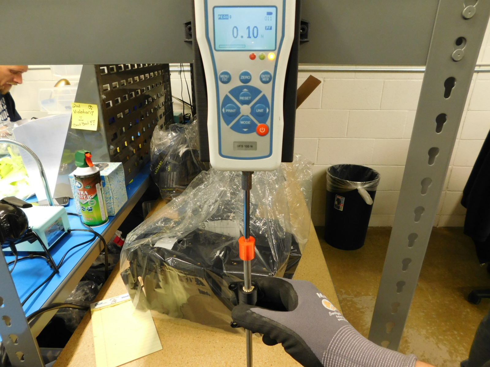
If the YELLOW light turns on, the bushing set is below the minimum allowed drag force.
To increase the drag, tighten the compression fasteners in even increments.
Repeat the drag check until the bushing set is within spec.
If the RED light turns on, the bushing set is over the maximum allowed drag force.
To reduce the drag, loosen the compression fasteners in even increments.
Repeat the drag check until the bushing set is within spec.


Drag specifications for 10mm single bushings:
Max allowed drag force: 5N
10mm single bushings do not have adjustable compression, the drag force should be checked prior to using the parts in an assembly.
Check the drag force using the force gauge:
Ensure the 10mm test rod is installed on the force gauge DO NOT OVERTIGHTEN; FINGER TIGHT ONLY
Turn on the force gauge by pressing the power button
Slide the bushing to be checked onto the test rod
Press the reset button and then the zero button
Pull the part downward on the rod
To repeat the test, slide the part back up and press the reset button again
If the GREEN light turns on, the part is good to use.
If the YELLOW light turns on, the bushing set is below the minimum drag spec, but for single bushings this is good to use.
If the RED light turns on, the bushing set is over the maximum allowed drag force.
Ensure the bearing is properly installed in the part, if the drag is still too high red tag the part.


Drag specifications for 12mm double bushings:
Max allowed drag force: 5N
Minimum drag force: 3N
To set 12mm double bushing sets to the correct drag force, begin by tightening both compression screws in even increments until the plastic tabs begin to compress towards the bushings.
Check the drag force using the force gauge:
Ensure the 12mm test rod is installed on the force gauge DO NOT OVERTIGHTEN; FINGER TIGHT ONLY
Turn on the force gauge by pressing the power button
Slide the bushing set to be checked onto the test rod
Press the reset button and then the zero button
Pull the bushing set downward on the rod
To repeat the test, slide the part back up and press the reset button again
If the GREEN light turns on, the bushing set is calibrated correctly
If the YELLOW light turns on, the bushing set is below the minimum allowed drag force.
To increase the drag, tighten the compression fasteners in even increments.
Repeat the drag check until the bushing set is within spec.
If the RED light turns on, the bushing set is over the maximum allowed drag force.
To reduce the drag, loosen the compression fasteners in even increments.
Repeat the drag check until the bushing set is within spec.


Drag specifications for 12mm single bushings:
Max allowed drag force: 5N
Minimum drag force: 3N
To set 12mm single bushings to the correct drag force, begin by tightening the compression screw until the plastic tabs begin to compress towards the bushing.
Check the drag force using the force gauge:
Ensure the 12mm test rod is installed on the force gauge DO NOT OVERTIGHTEN; FINGER TIGHT ONLY
Turn on the force gauge by pressing the power button
Slide the bushing set to be checked onto the test rod
Press the reset button and then the zero button
Pull the bushing set downward on the rod
To repeat the test, slide the part back up and press the reset button again
If the GREEN light turns on, the bushing set is calibrated correctly
If the YELLOW light turns on, the bushing set is below the minimum allowed drag force.
To increase the drag, tighten the compression fastener.
Repeat the drag check until the bushing set is within spec.
If the RED light turns on, the bushing set is over the maximum allowed drag force.
To reduce the drag, loosen the compression fastener.
Repeat the drag check until the bushing set is within spec.


Drag specifications for 8mm double bushings:
Max allowed drag force: 5N
8mm double bushings do not have adjustable compression, the drag force should be checked prior to using the parts in an assembly.
Check the drag force using the force gauge:
Ensure the 8mm test rod is installed on the force gauge DO NOT OVERTIGHTEN; FINGER TIGHT ONLY
Turn on the force gauge by pressing the power button
Slide the bushing to be checked onto the test rod
Press the reset button and then the zero button
Pull the part downward on the rod
To repeat the test, slide the part back up and press the reset button again
If the GREEN light turns on, the part is good to use.
If the YELLOW light turns on, the bushing set is below the minimum drag spec, but for 8mm double bushings this is good to use.
If the RED light turns on, the bushing set is over the maximum allowed drag force.
Ensure the bearing is properly installed in the part, if the drag is still too high red tag the part.


Drag specifications for 8mm single bushings:
Max allowed drag force: 5N
8mm single bushings do not have adjustable compression, the drag force should be checked prior to using the parts in an assembly.
Check the drag force using the force gauge:
Ensure the 8mm test rod is installed on the force gauge DO NOT OVERTIGHTEN; FINGER TIGHT ONLY
Turn on the force gauge by pressing the power button
Slide the bushing to be checked onto the test rod
Press the reset button and then the zero button
Pull the part downward on the rod
To repeat the test, slide the part back up and press the reset button again
If the GREEN light turns on, the part is good to use.
If the YELLOW light turns on, the bushing set is below the minimum drag spec, but for single bushings this is good to use.
If the RED light turns on, the bushing set is over the maximum allowed drag force.
Ensure the bearing is properly installed in the part, if the drag is still too high red tag the part.