Open HardwareAssembly Instructions
Guides for installation and assembly of the LulzBot line of products made by FAME 3D LLC.
Guides for installation and assembly of the LulzBot line of products made by FAME 3D LLC.
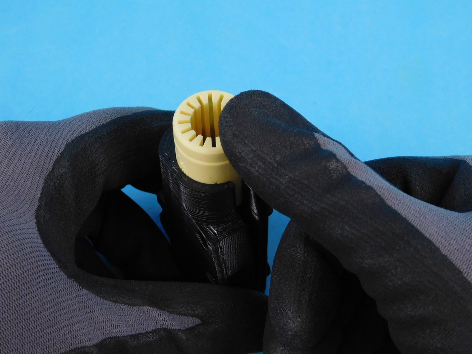
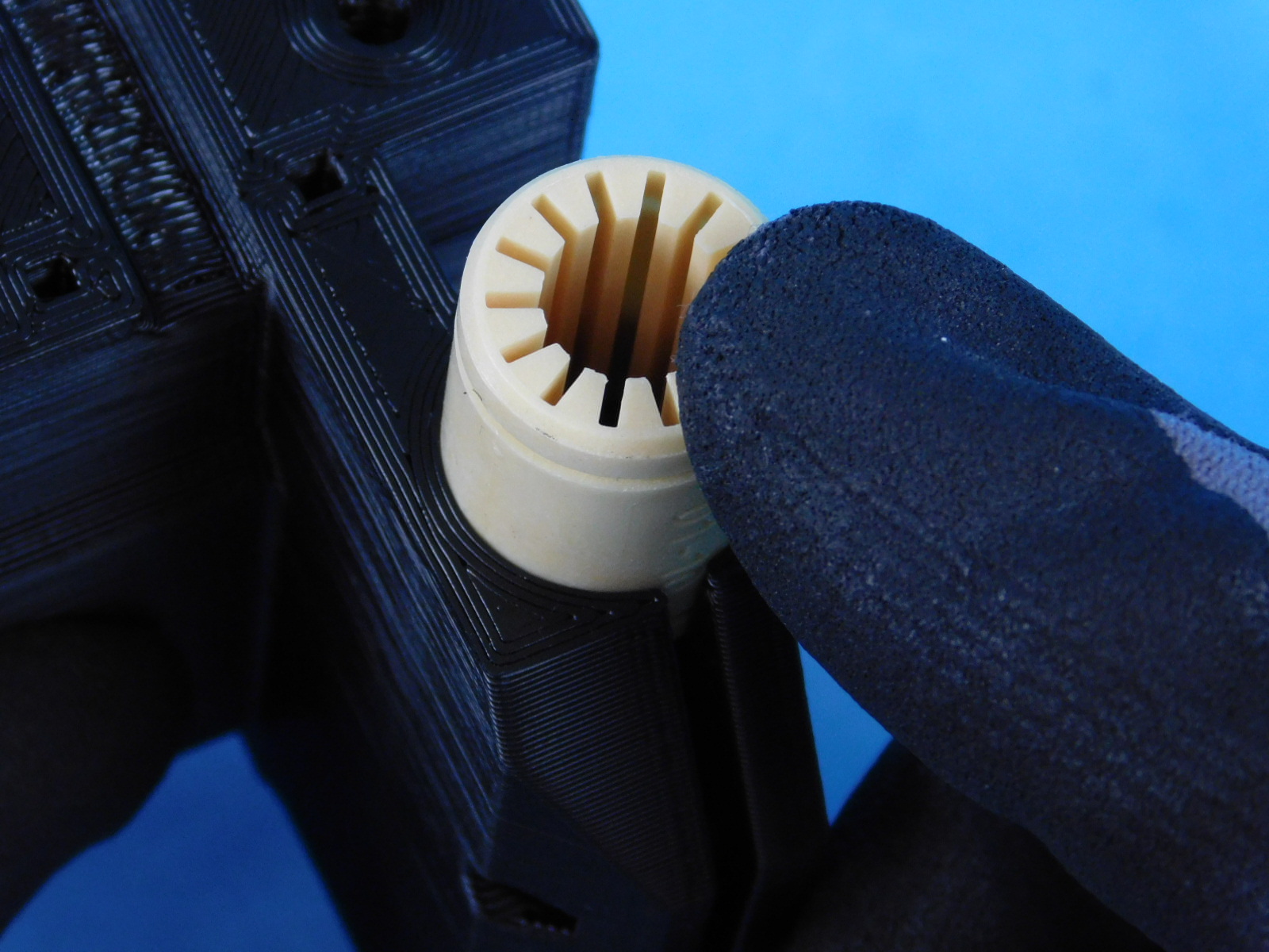
Before installing a self aligning bushing (has metal sleeve), slide it onto a smooth rod to ensure it is smooth with no excessive drag.
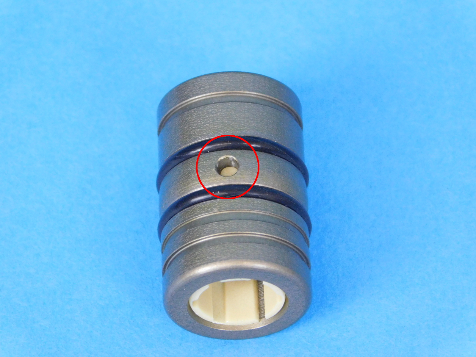
If excessive drag is present, verify that the notch on the inner bearing material is aligned with the hole in the outer metal casing.
If needed, use a flat screwdriver to rotate the bushing in the housing until the plastic tab on the outer wall of the bushing is aligned with the hole in the aluminum housing.
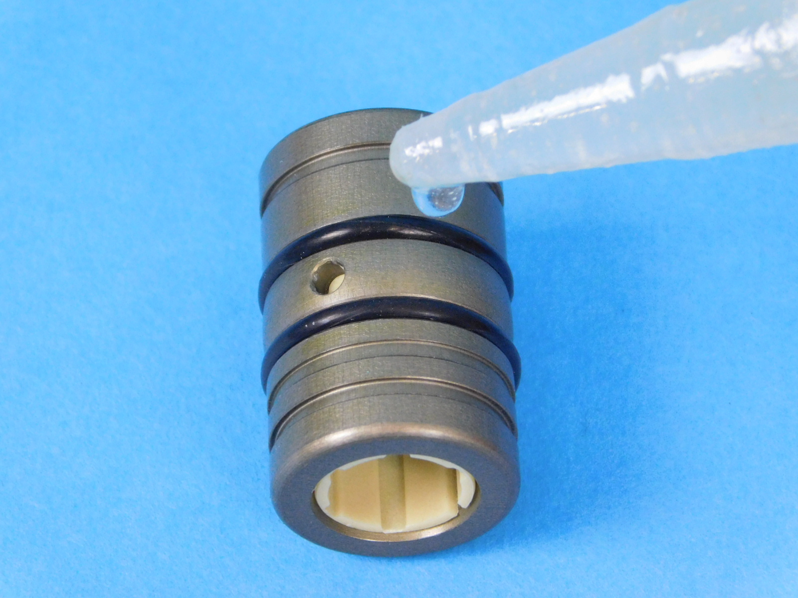
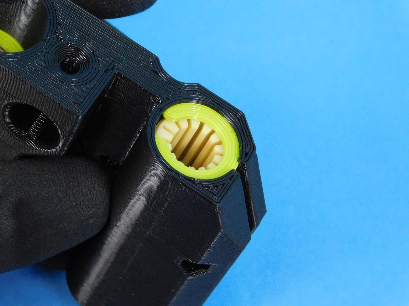
Lubricate the o-rings on the outside of the bearing using Superlube [TL-CS0011]
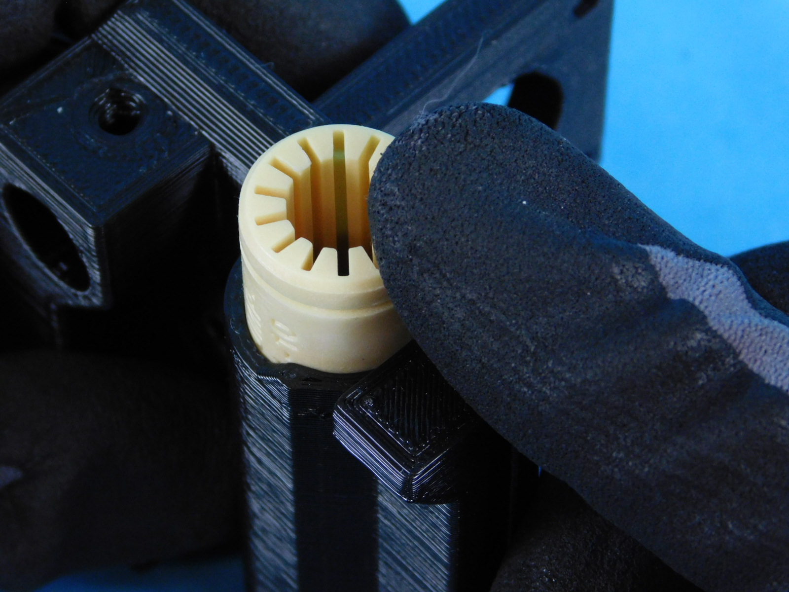
Push the bushing into the desired placement by hand or with an arbor press.


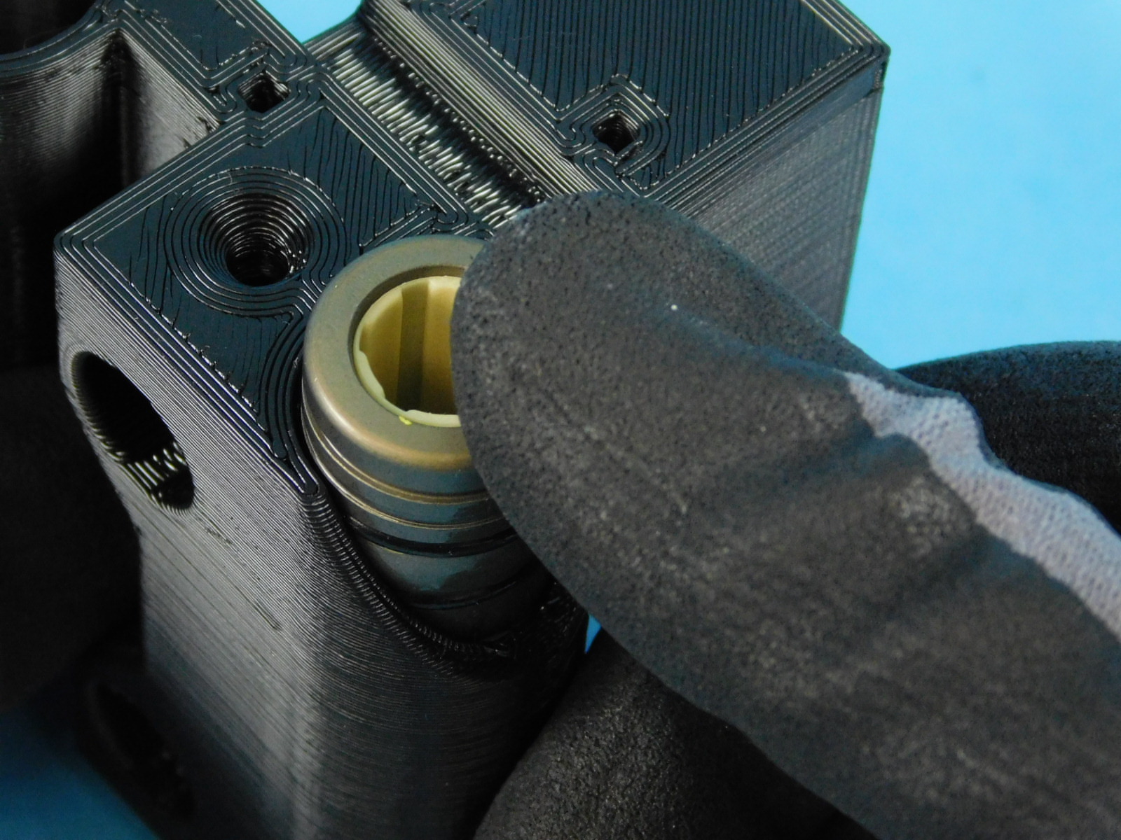
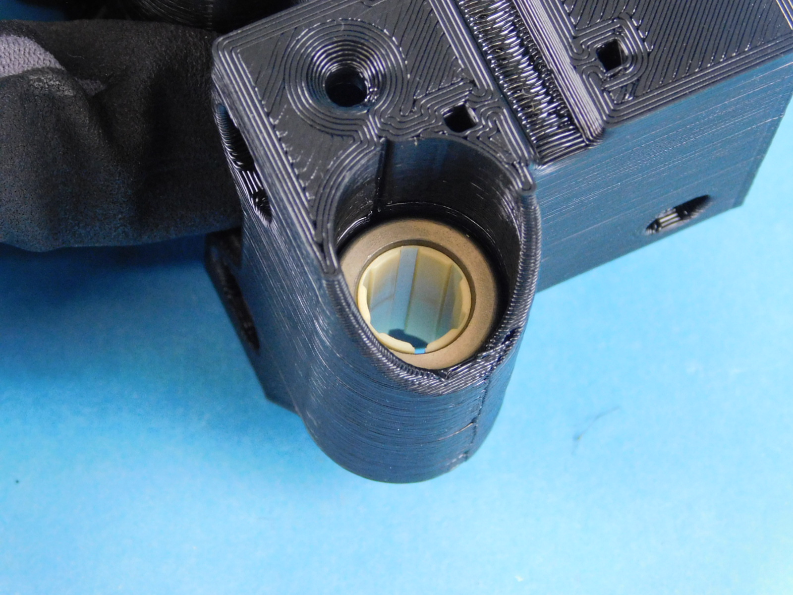

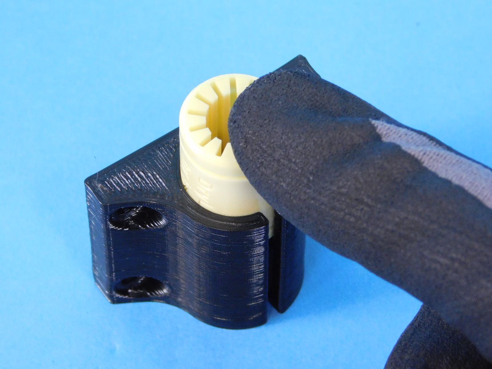
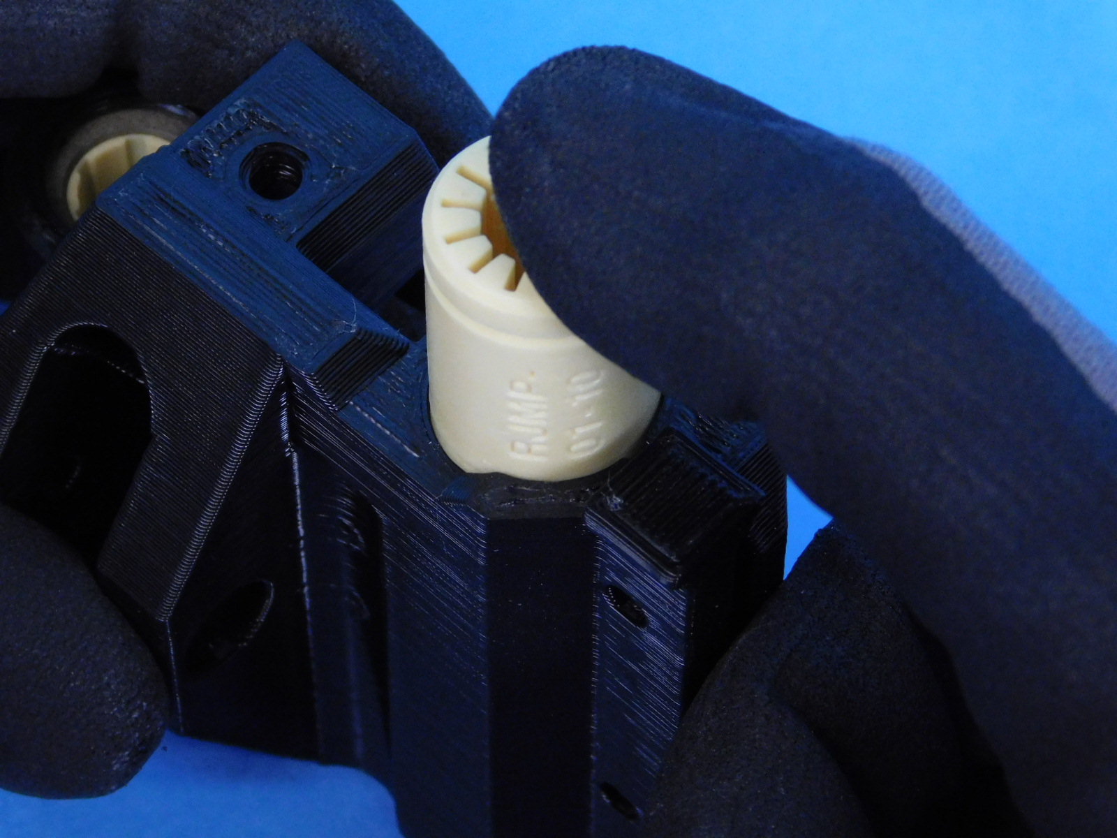
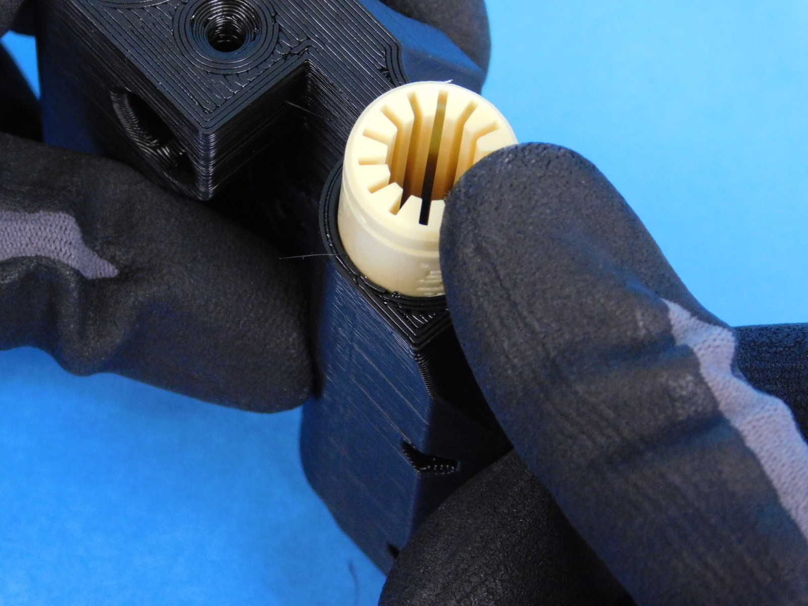
12mm linear bearings can be installed by hand
See photos for installation direction

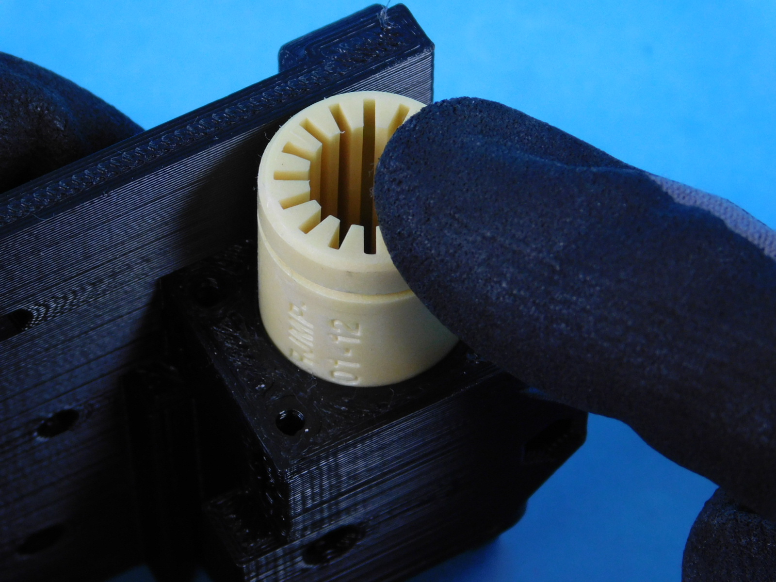
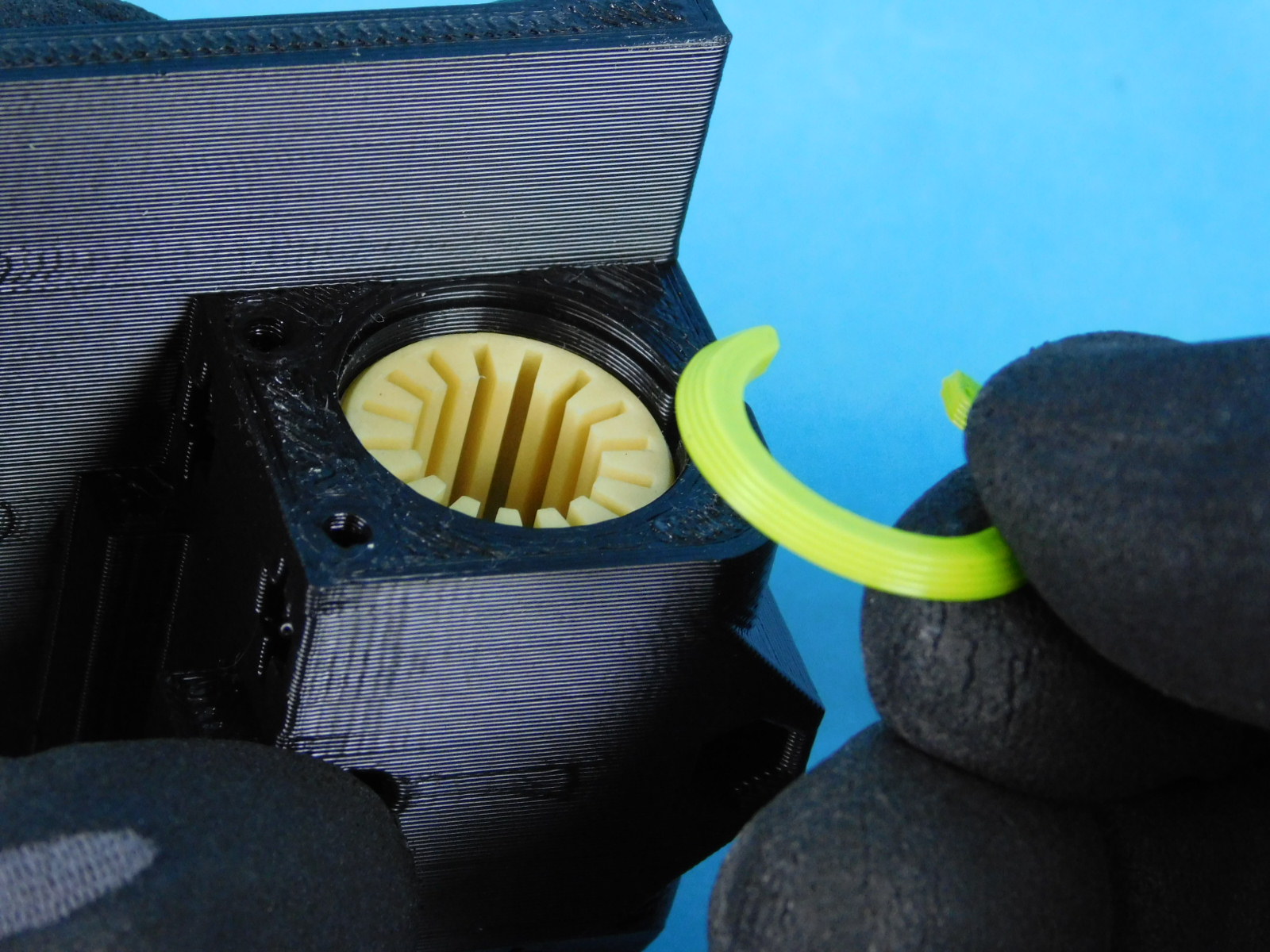
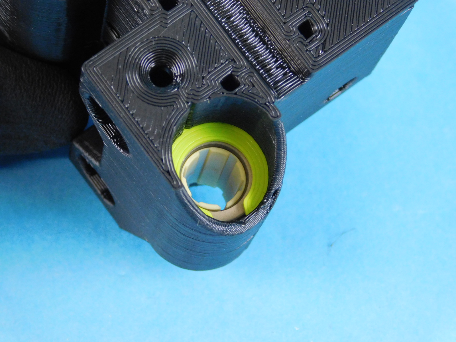
10mm linear bearings can be installed by hand into X End Motor, X End Idler, and Y Bearing Holder
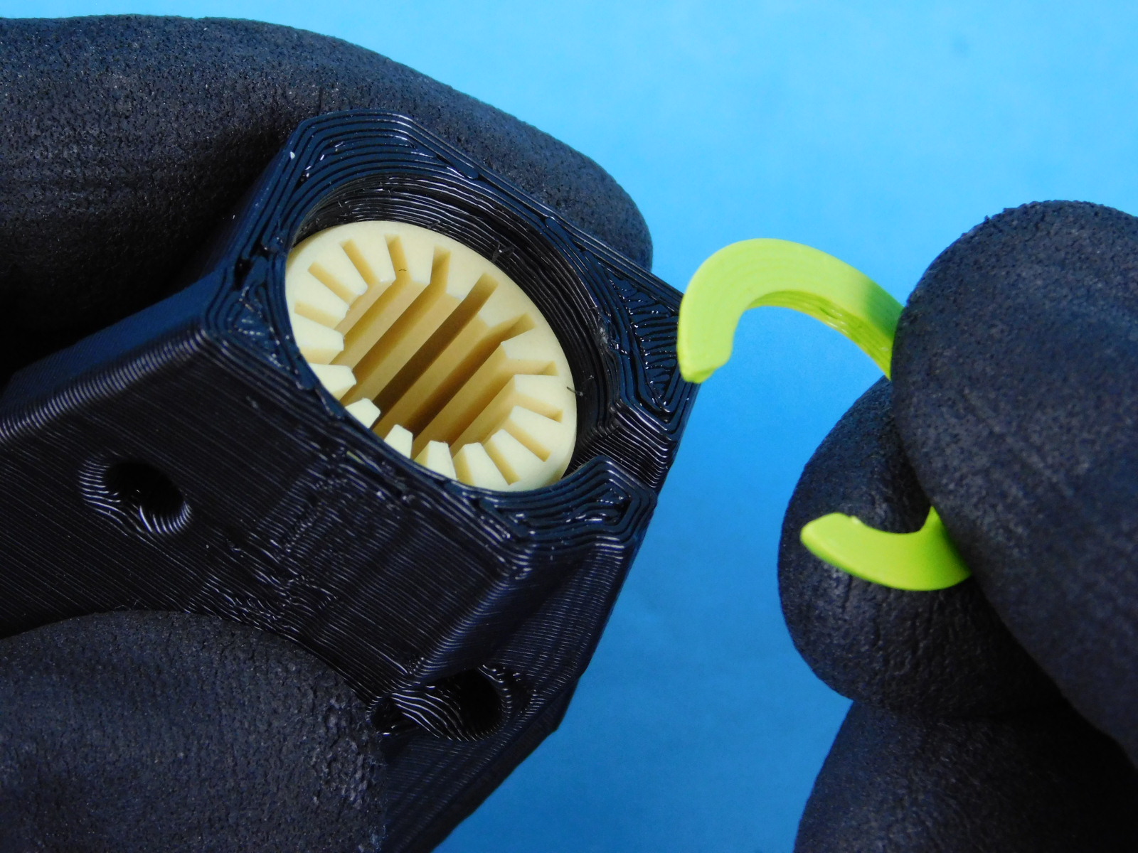
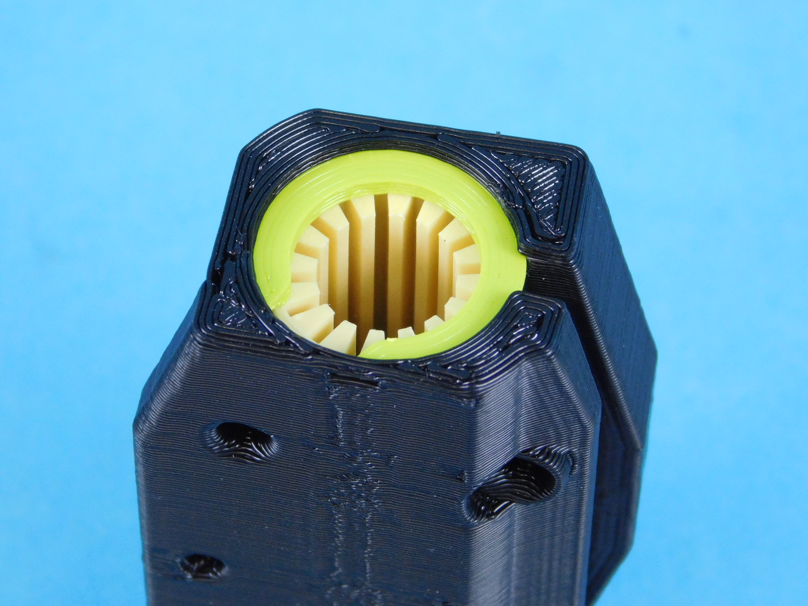
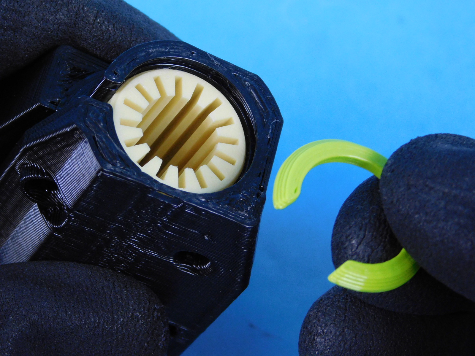
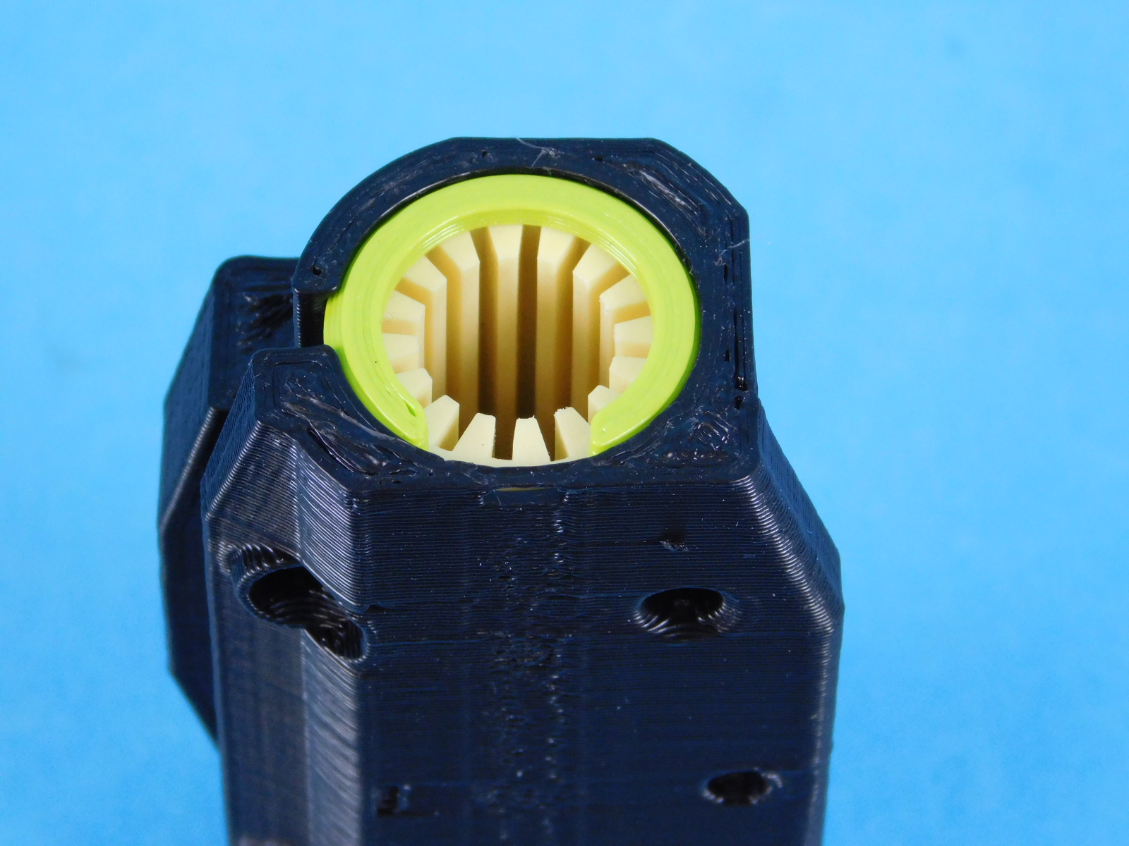
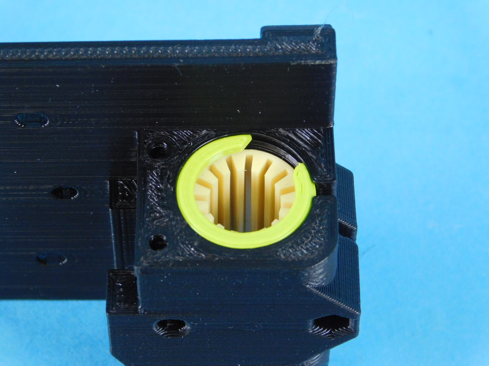
See photos for installation direction and retaining ring orientation
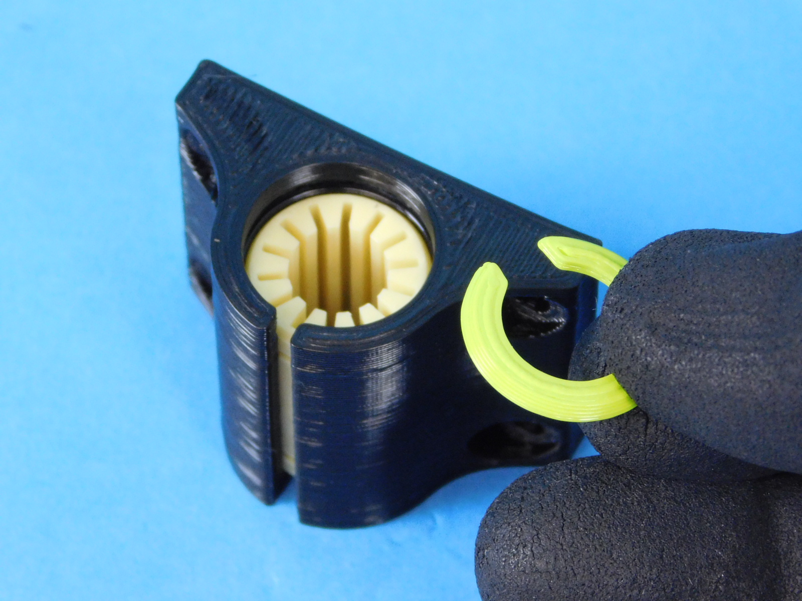
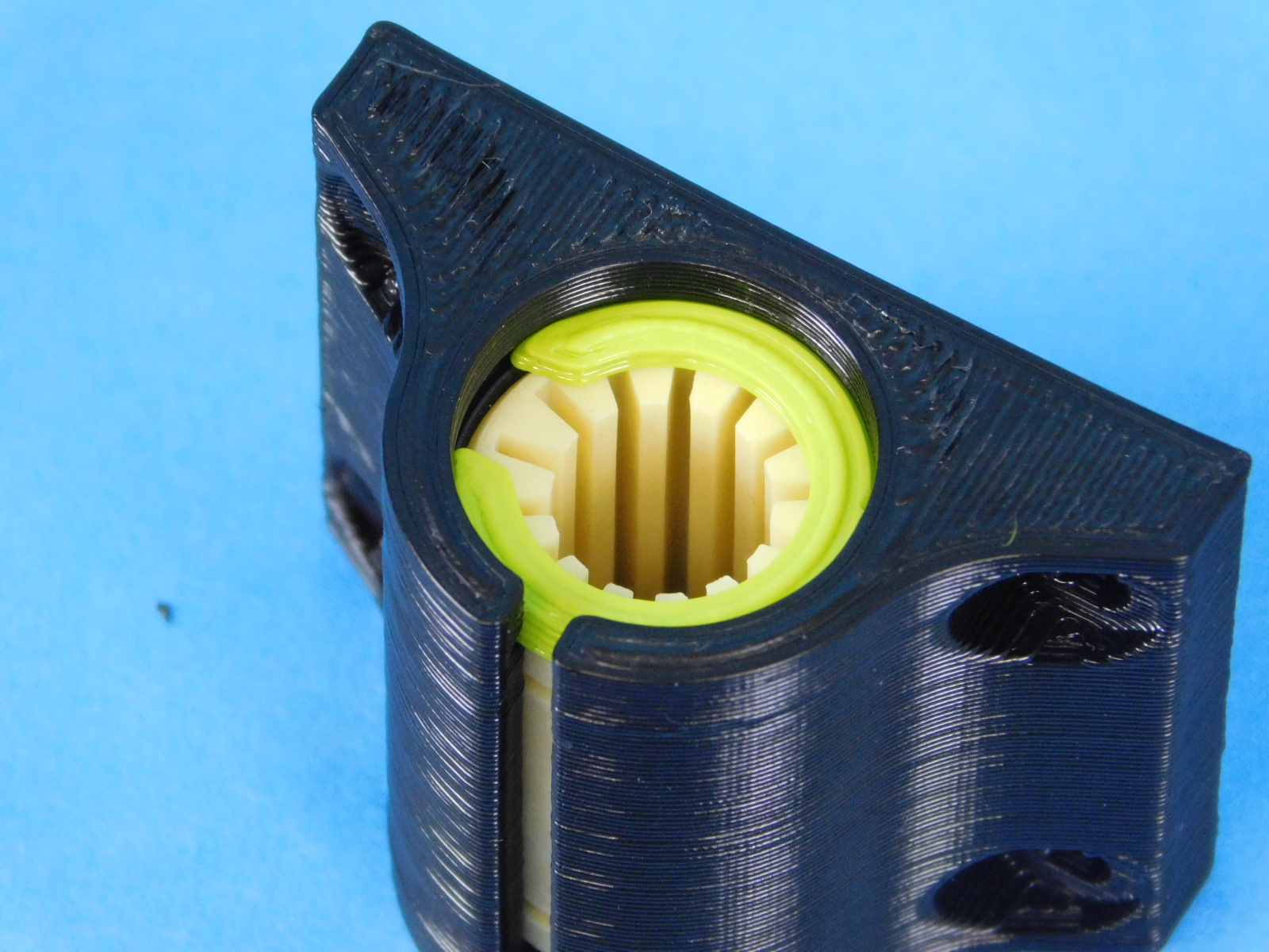
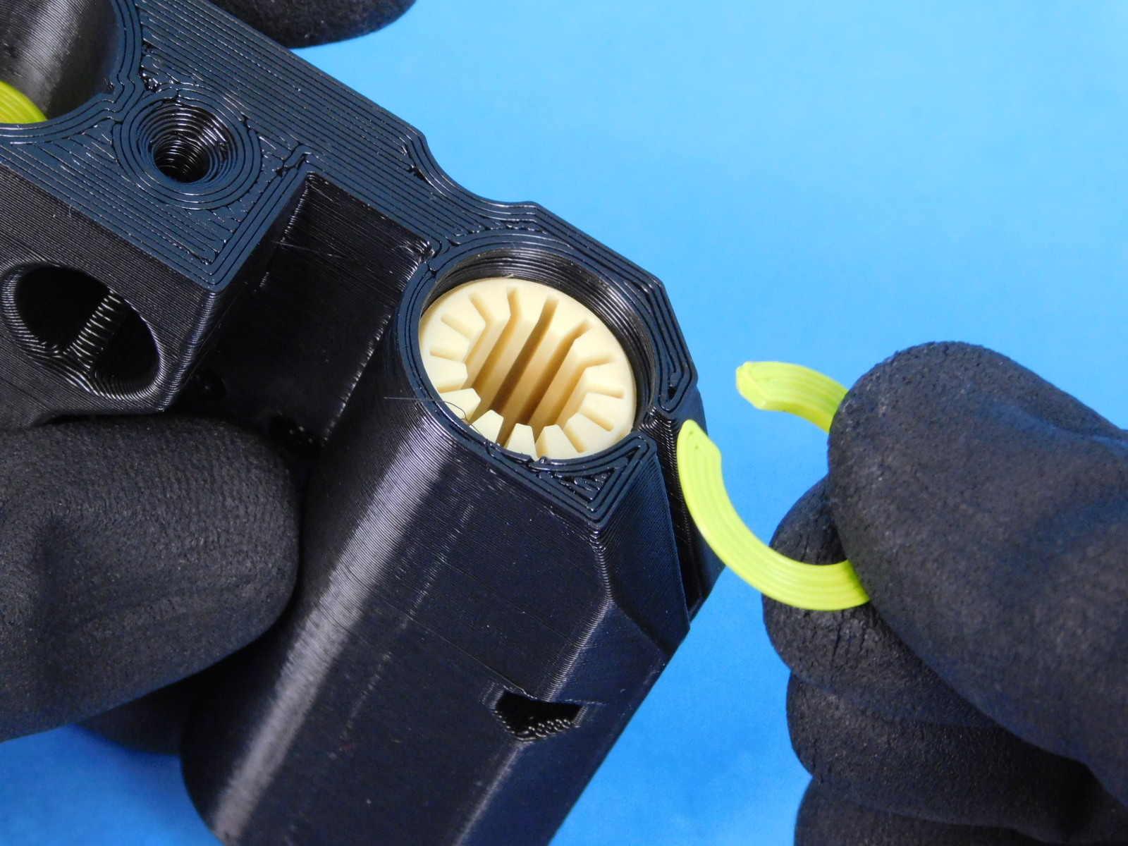
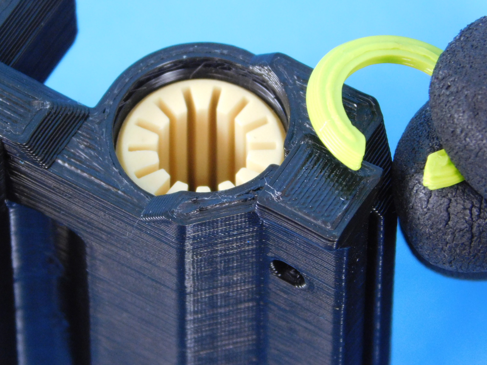
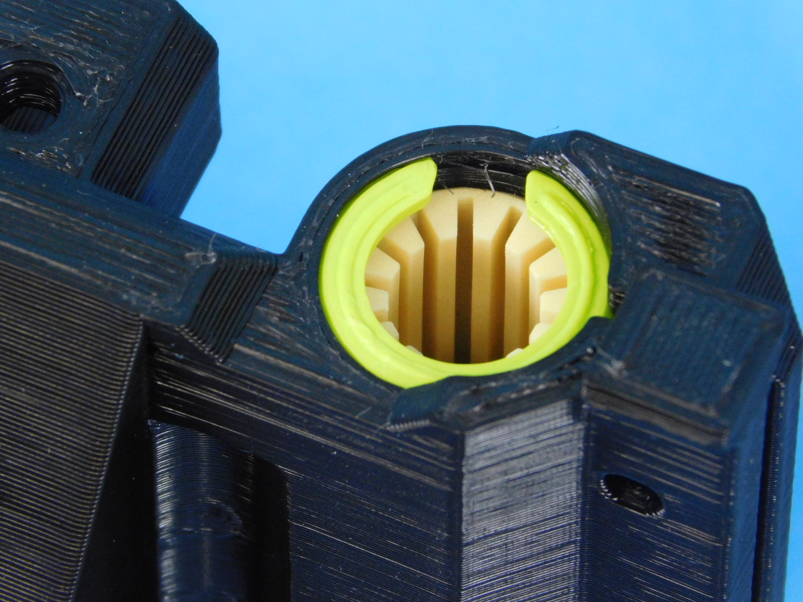

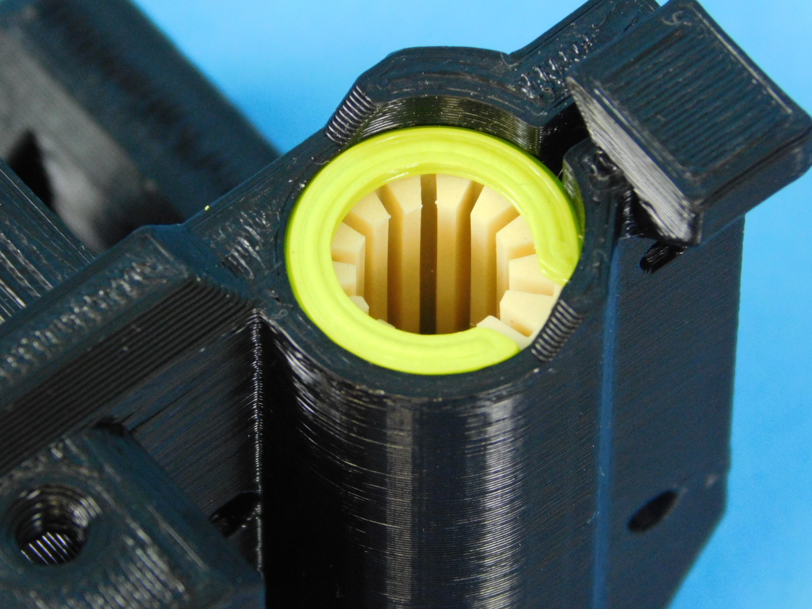
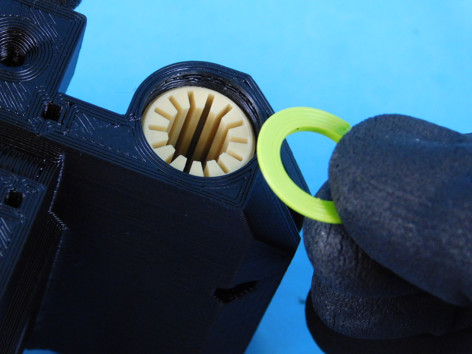
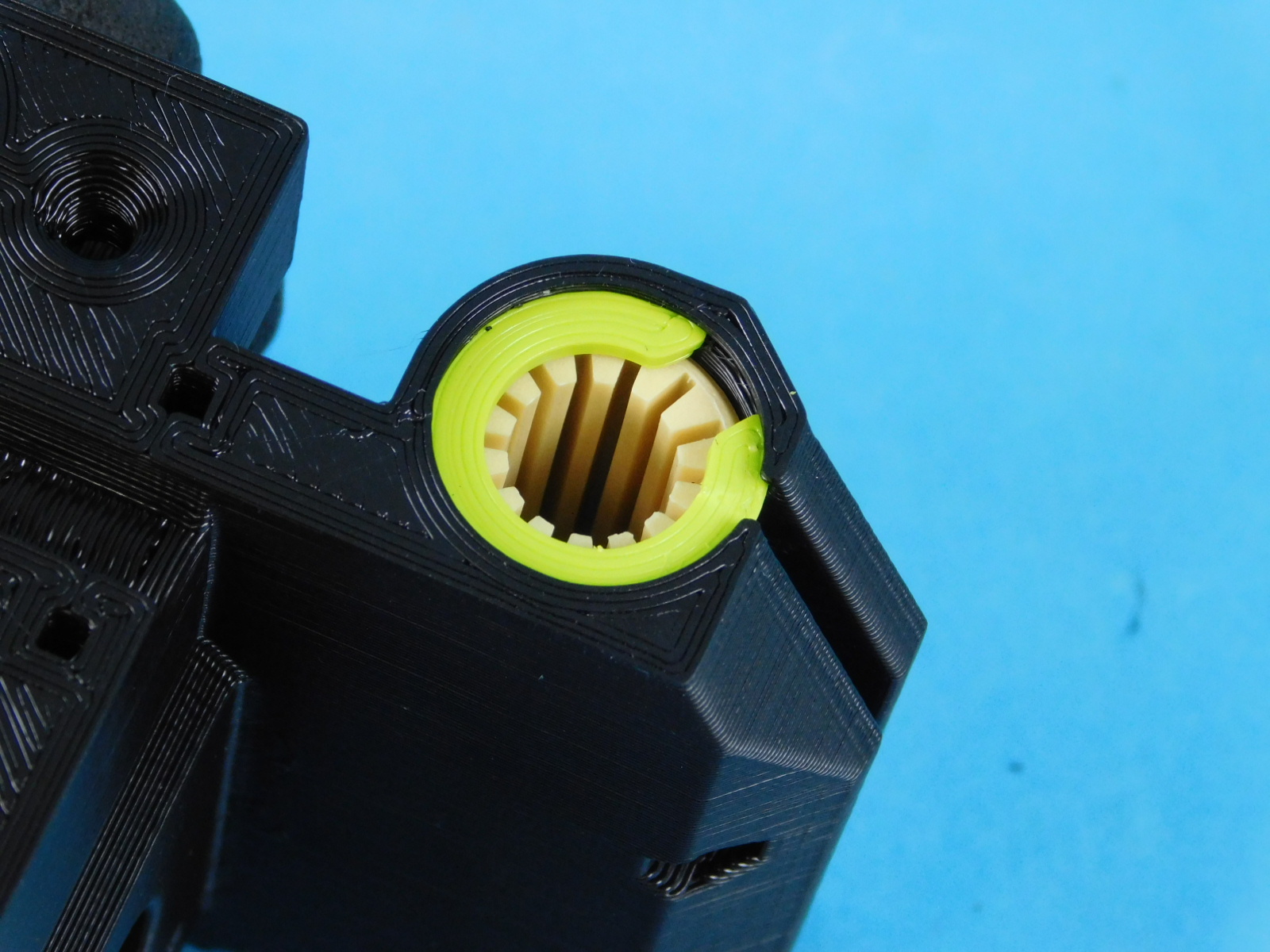
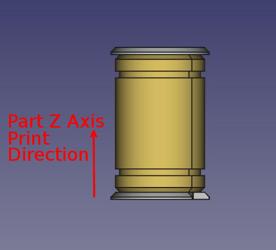
In all circumstances, the retaining rings should be installed with the chamfered side facing up in reference to the Z axis print direction of the part.
Refer to illustration at right
If installing a retaining ring on the bottom (bed side) of the part, the chamfer should be facing the bearing.
If installing a retaining ring on the top side of the part (opposite the bed side) the chamfer of the retaining ring should be facing away from the bearing.