Open HardwareAssembly Instructions
Guides for installation and assembly of the LulzBot line of products made by FAME 3D LLC.
Guides for installation and assembly of the LulzBot line of products made by FAME 3D LLC.
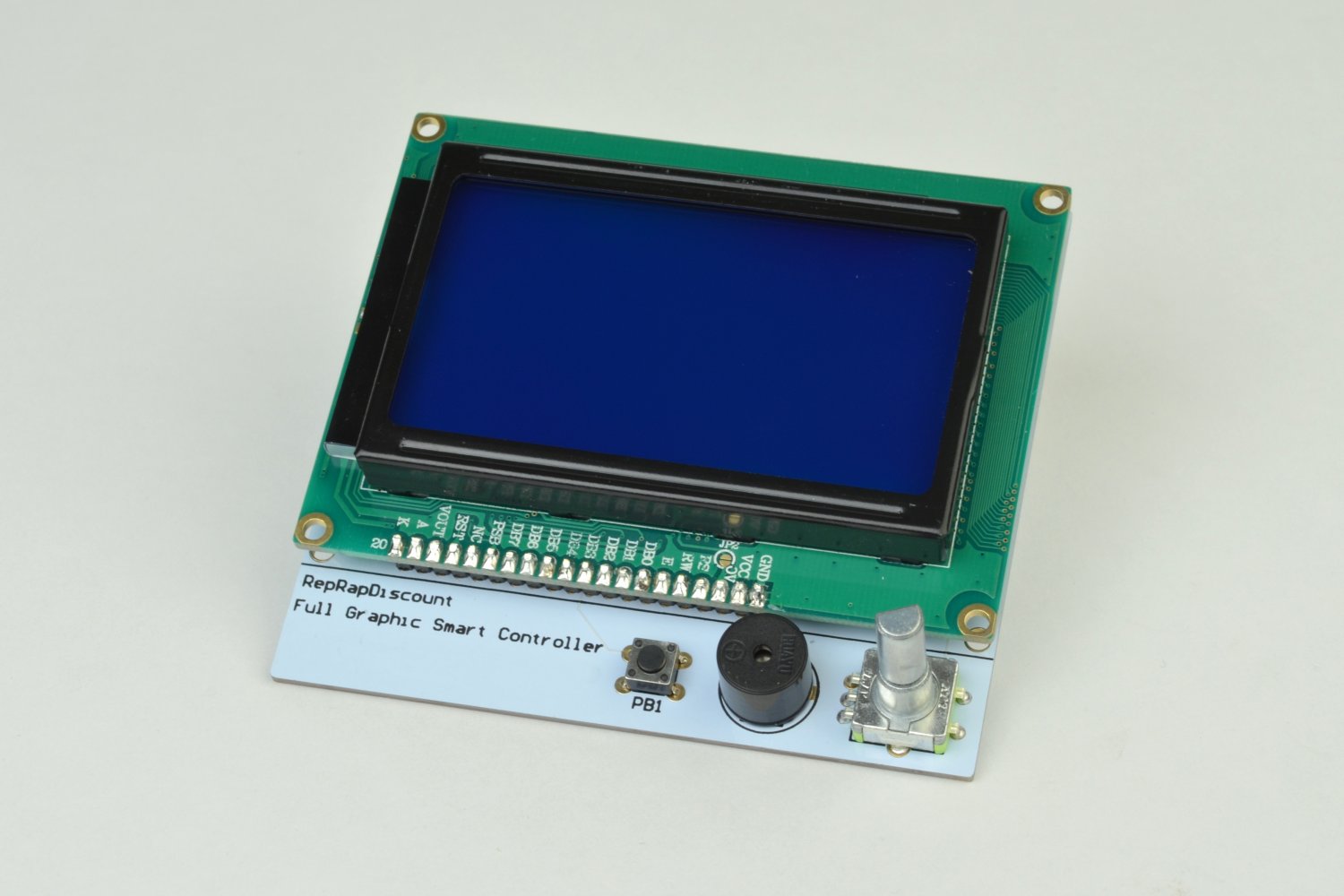
The Graphical LCD Controller (GLCD) is an optional add-on for the KITTAZ 3D printer. This add-on allows for printing without being connected to a computer using its integrated SD card reader. You can also monitor your prints progress and view live information about temperatures, settings and modify some settings on the fly, without having to reflash the firmware.

Tools:
Available from LulzBot.com:
Additional materials needed from other vendors:
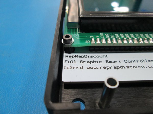
Install optional, printable LCD spacer between the circuit boards and drop a M2.5x12 Socket Head Cap screw with M2.5 washer through it.
Do this in all 4 corners of the board.
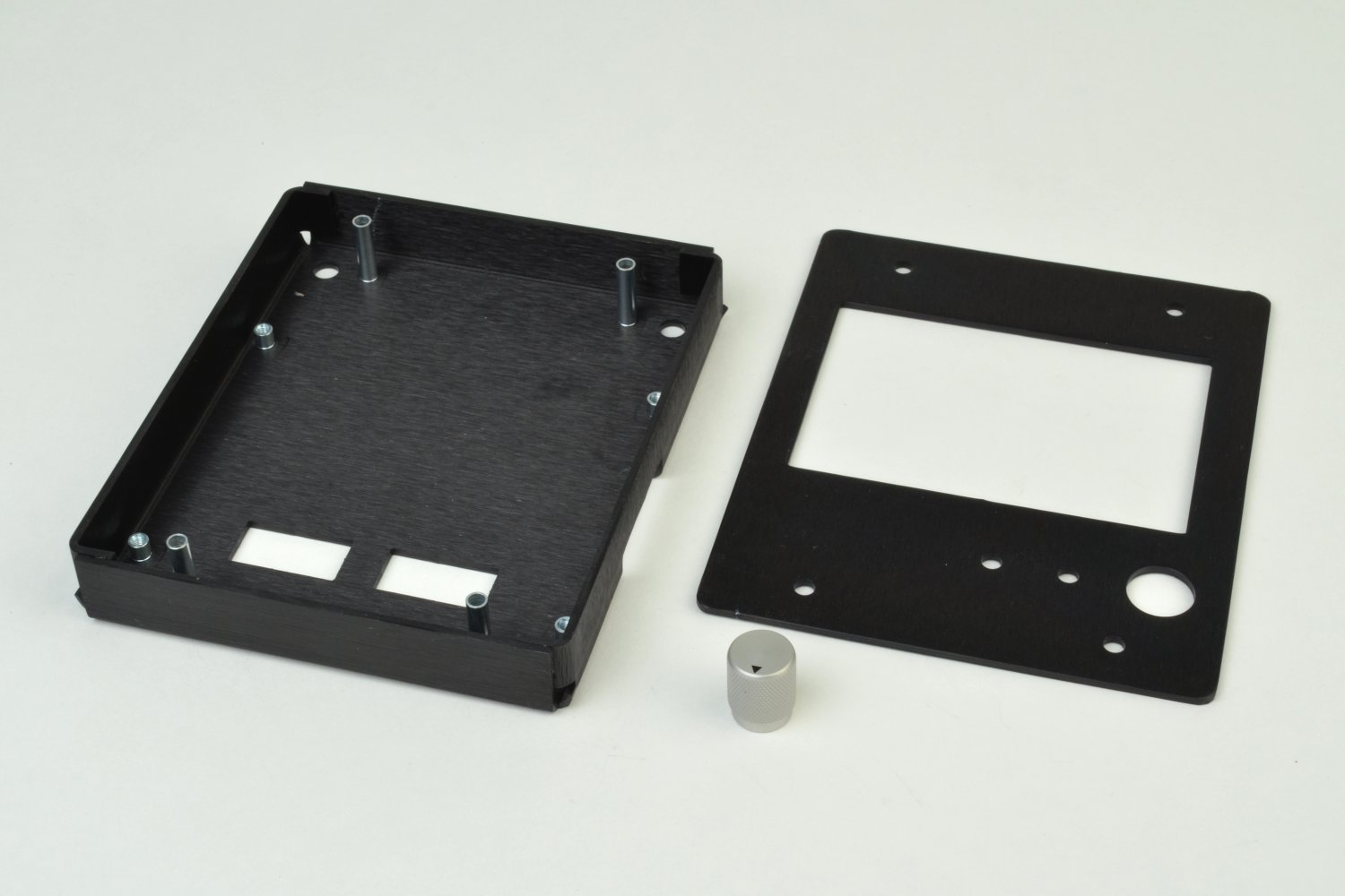
Set the LCD with screws down into the LCD case and tighten the screws down. If you decide not to use a spacer in each corner, do not over-tighten.
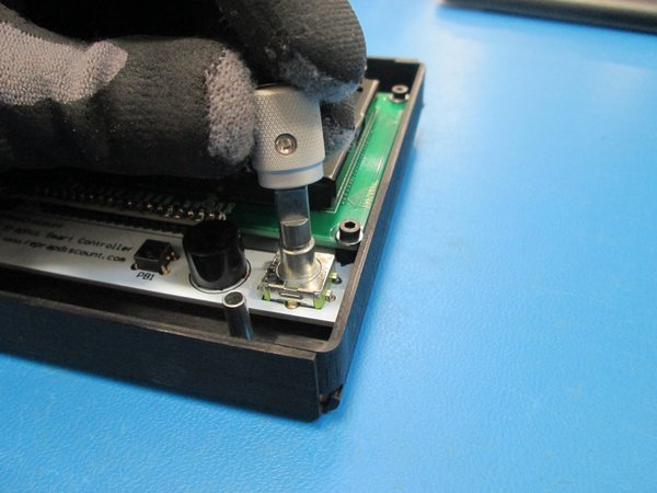
Install the knob onto the LCD with the set screw aligned with the flat.
The knob will go all the way down to a step on the shaft.
Tighten the set screw down using the 1-16 driver.

This next step is best performed with the Y axis assembly removed and with the main frame of the printer laying down.
Keep the two M5 tee-nuts in place on the printer frame and use the existing screws to secure the Graphical LCD controller enclosure onto the printer frame.
Once secured, install the Y axis assembly back into the printer frame.
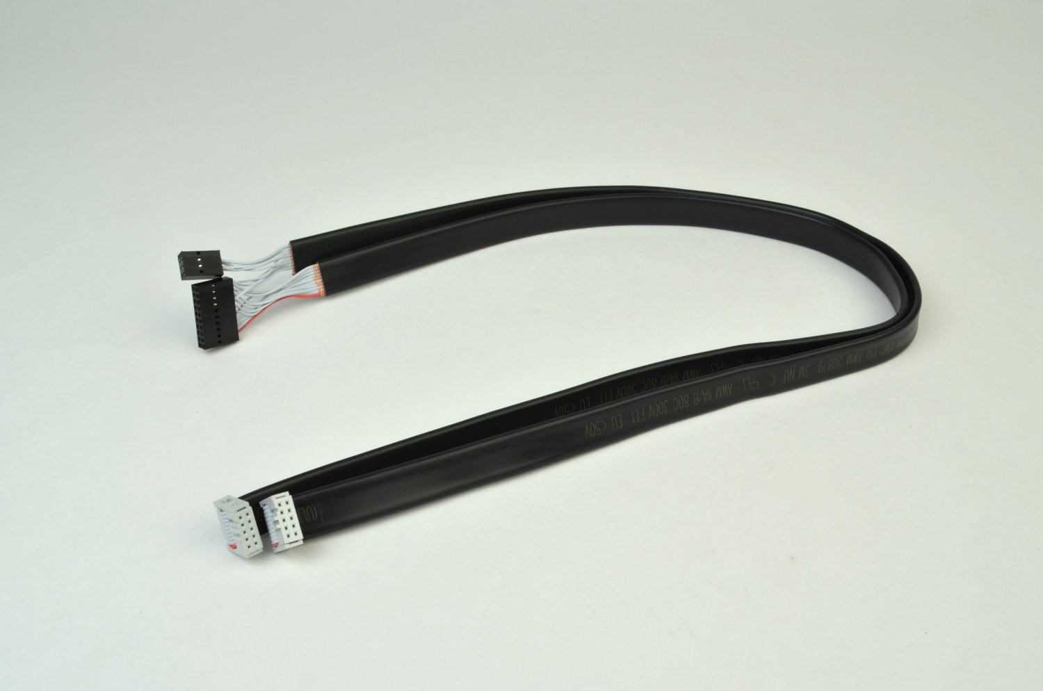
To identify the connectors on the wiring harness, follow the large black connector.
The connector EXP2 has wiring leading to both the large and small connector.
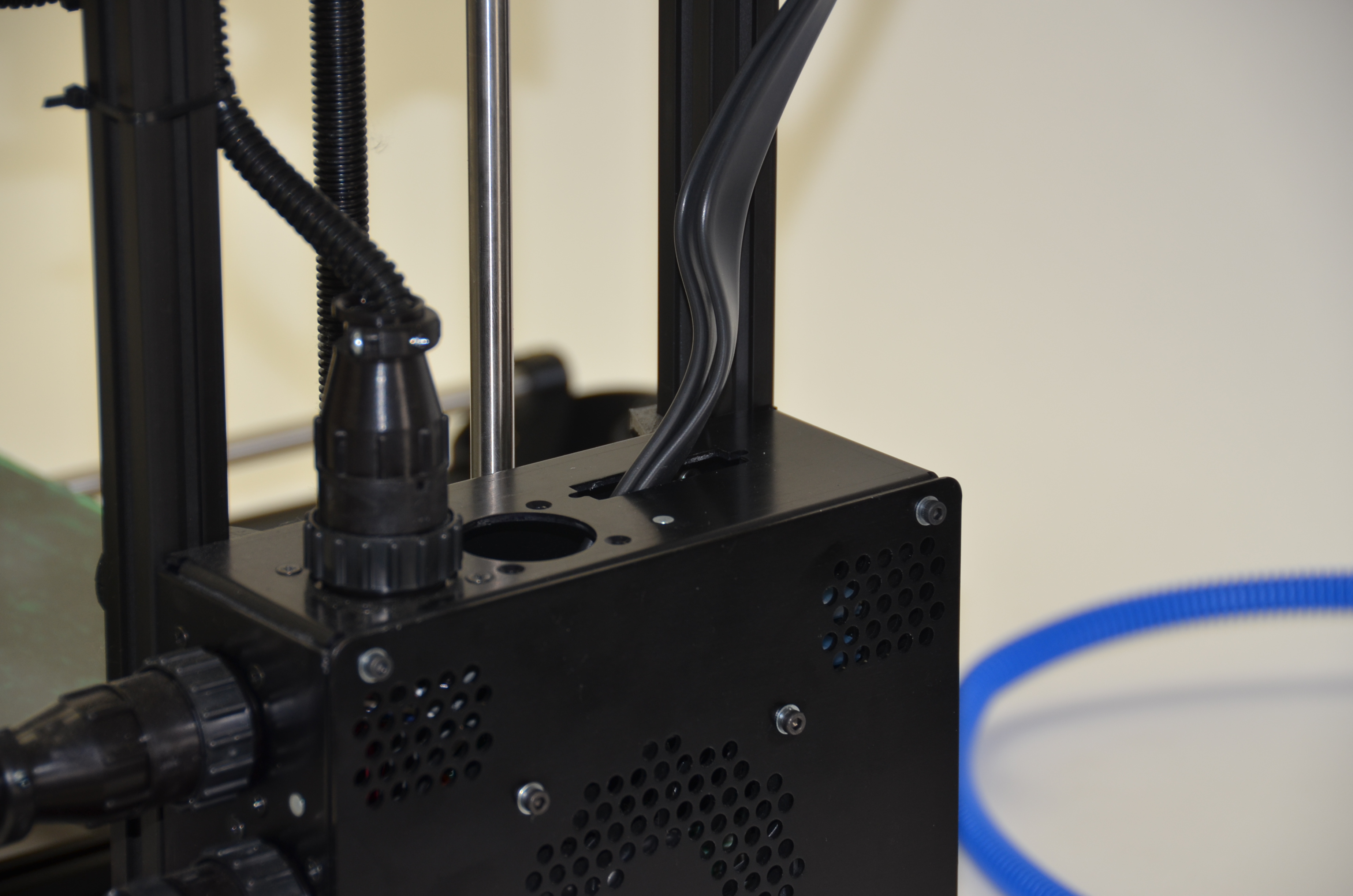
Connect EXP 1 to the left hand connector socket (when looking at the rear of the GLCD enclosure).
The red wire on the large black connector should be oriented so that it's close to the silver USB port.
The smaller connector is plugged into the connection labeled SP1. The connector is marked with a triangle to designate pin 1. SP1 is labeled with a small 1 to indicate orientation.
On each black connector match the black triangle to the Pin one locations noted on the board and in the image below.

Install the electronics enclosure lid using the 4 M3 screws.
Enjoy using your new Graphical LCD Controller!