Open HardwareAssembly Instructions
Guides for installation and assembly of the LulzBot line of products made by FAME 3D LLC.
Guides for installation and assembly of the LulzBot line of products made by FAME 3D LLC.
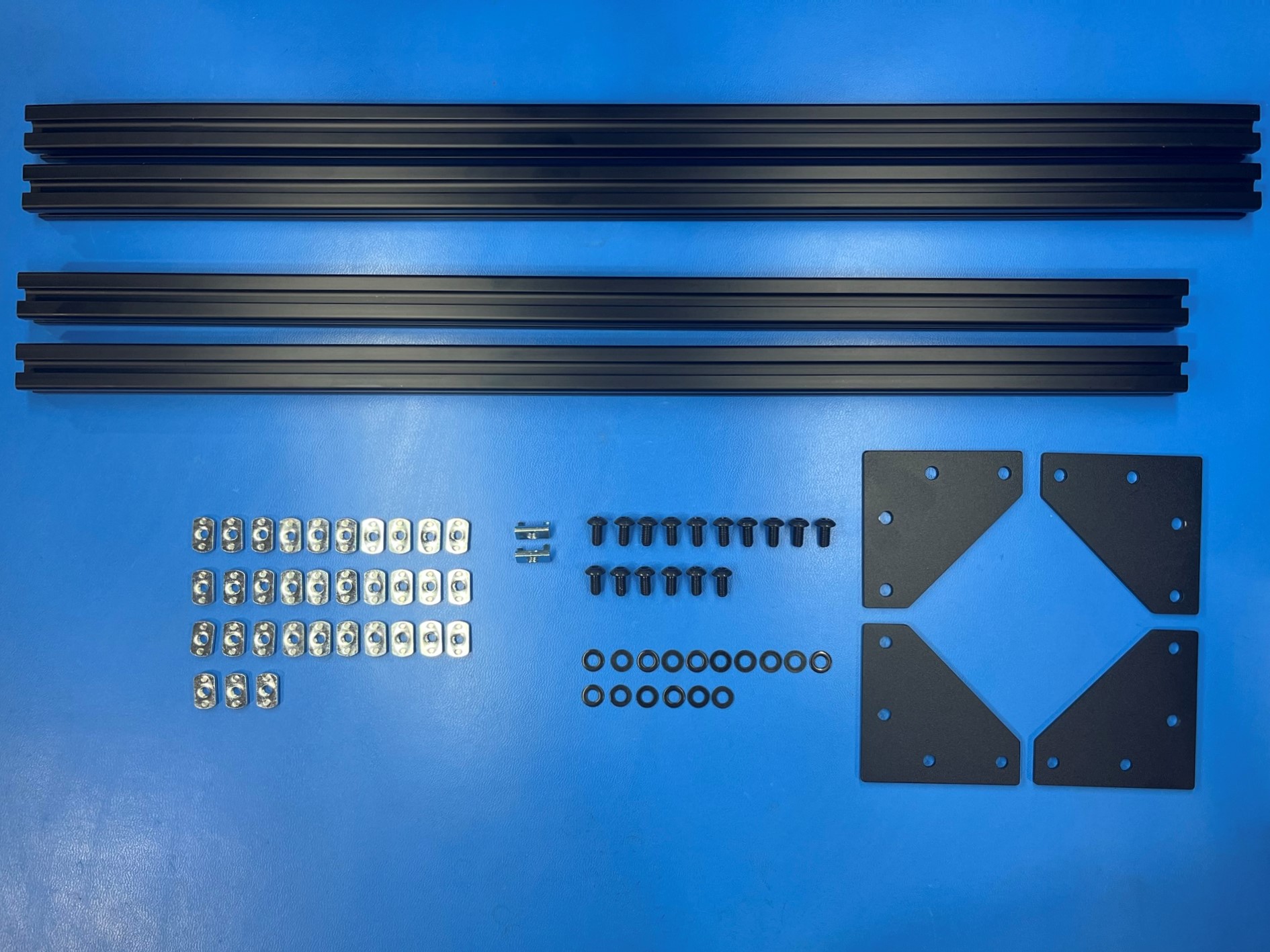
2x- [HD-EX0062] T-Slot Aluminum Extrusion 500mm
2x- [HD-EX0086] T-Slot Extrusion, Aluminum, 530mm
16x- [HD-BT0073] M5x10 BHCS, Black-Oxide
2x- [HD-NT0044] Post Assembly M5 T-Slot Nuts
33x- [HD-NT0053] M5 T-Slot Nuts
16x- [HD-WA0040] M5 Washers
4x- [PP-FP0152] Corner Bracket
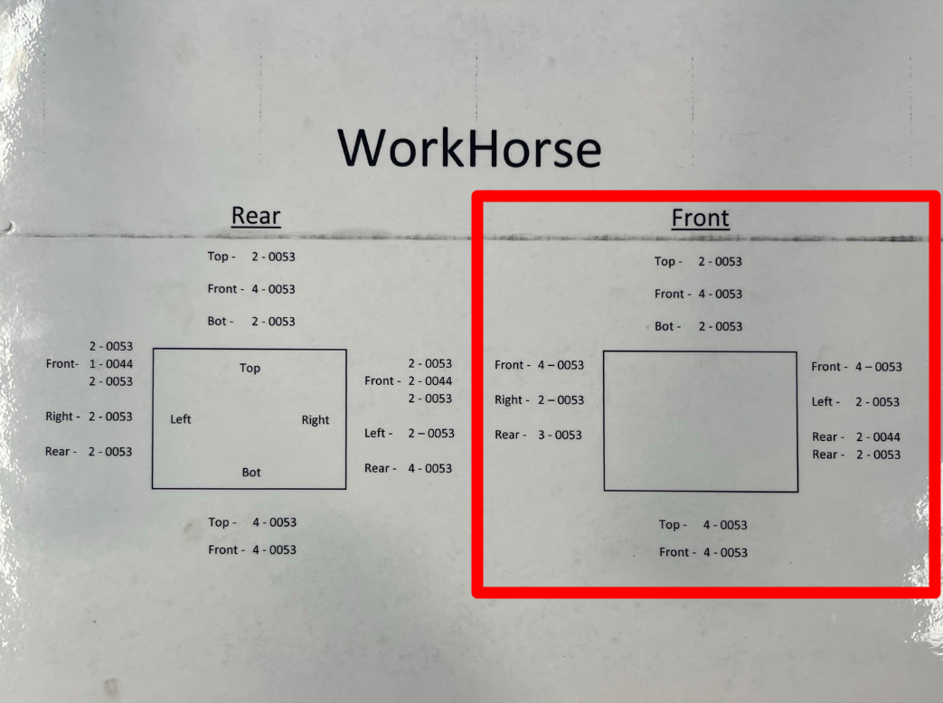
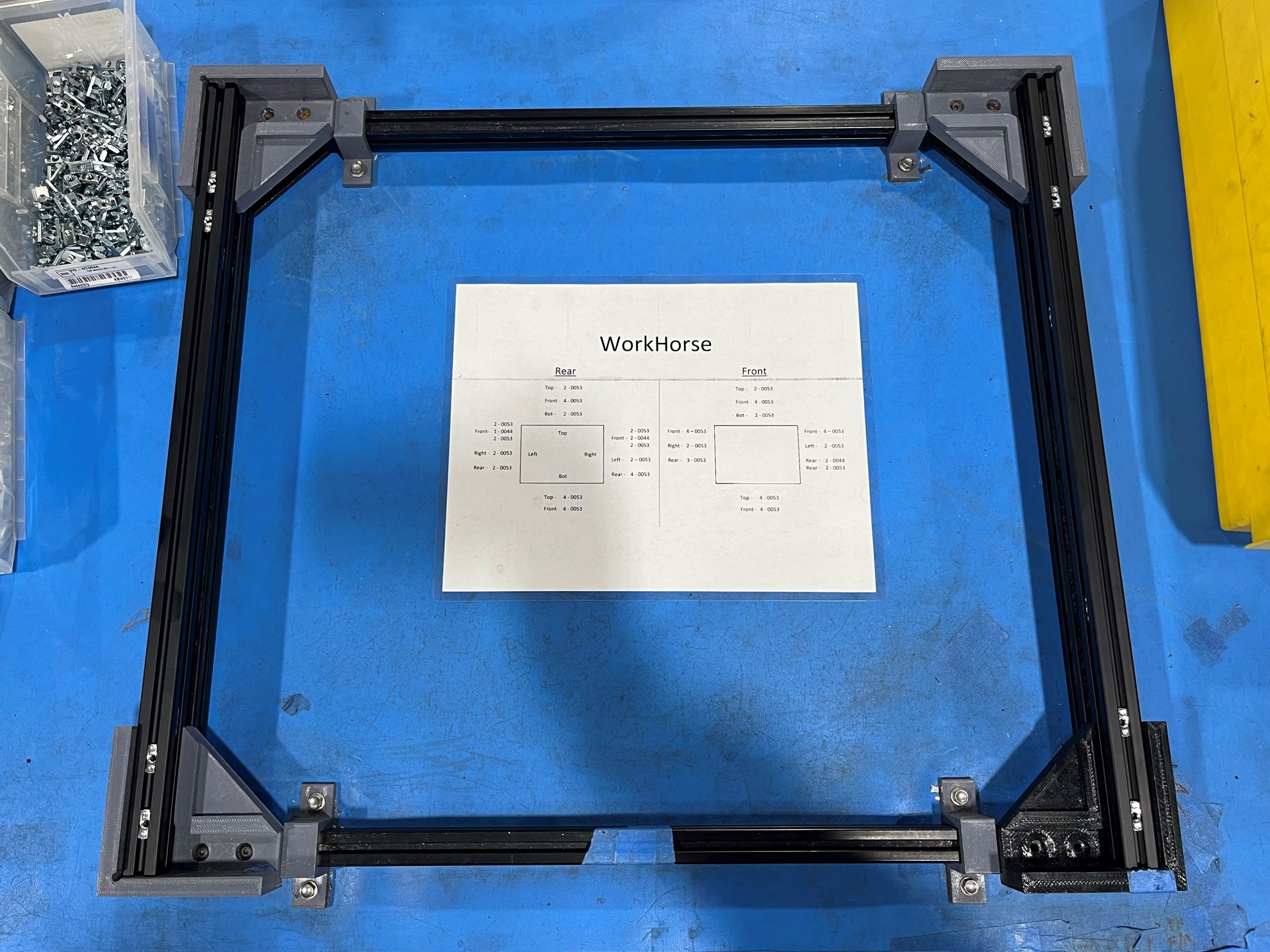
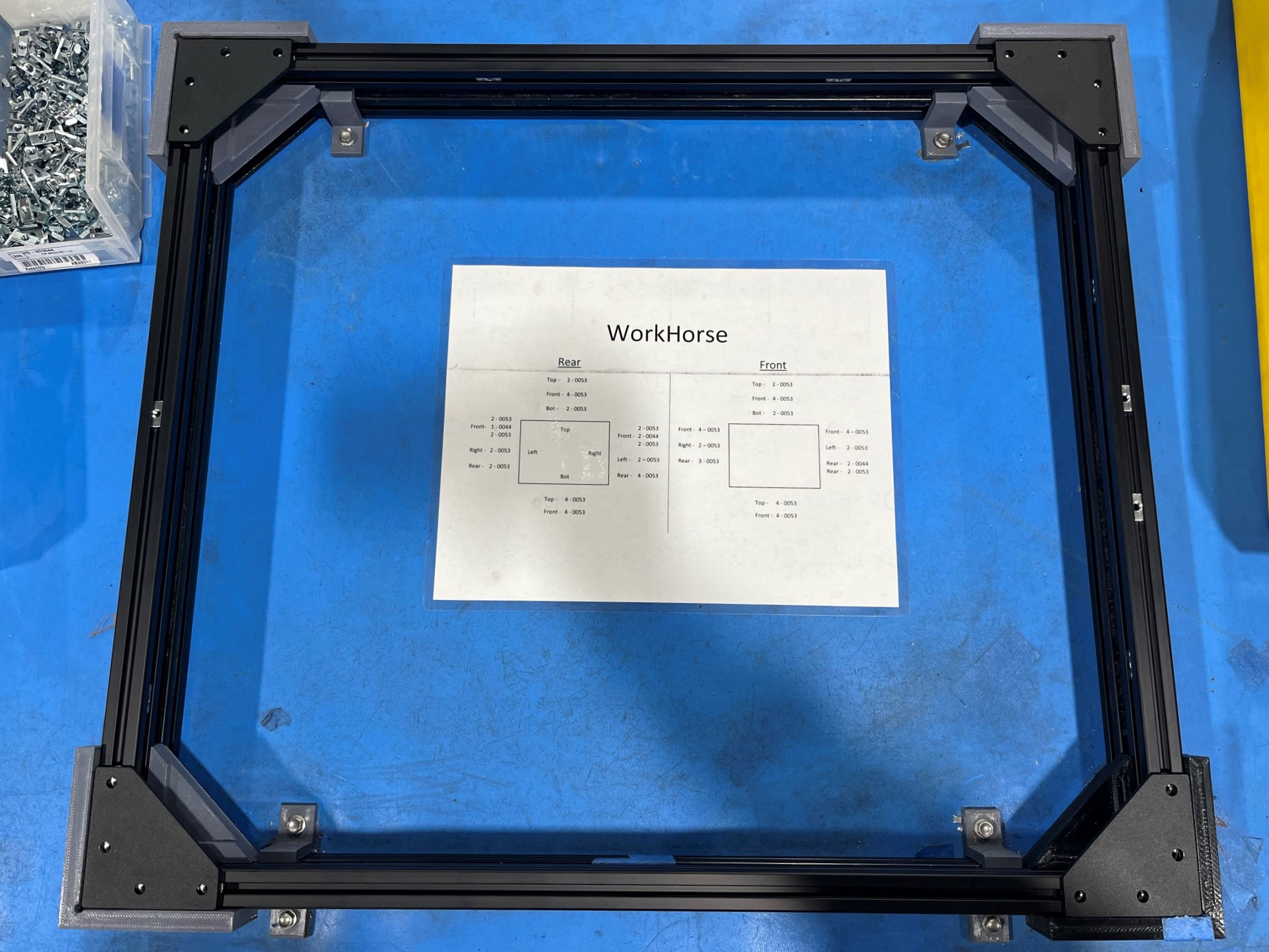
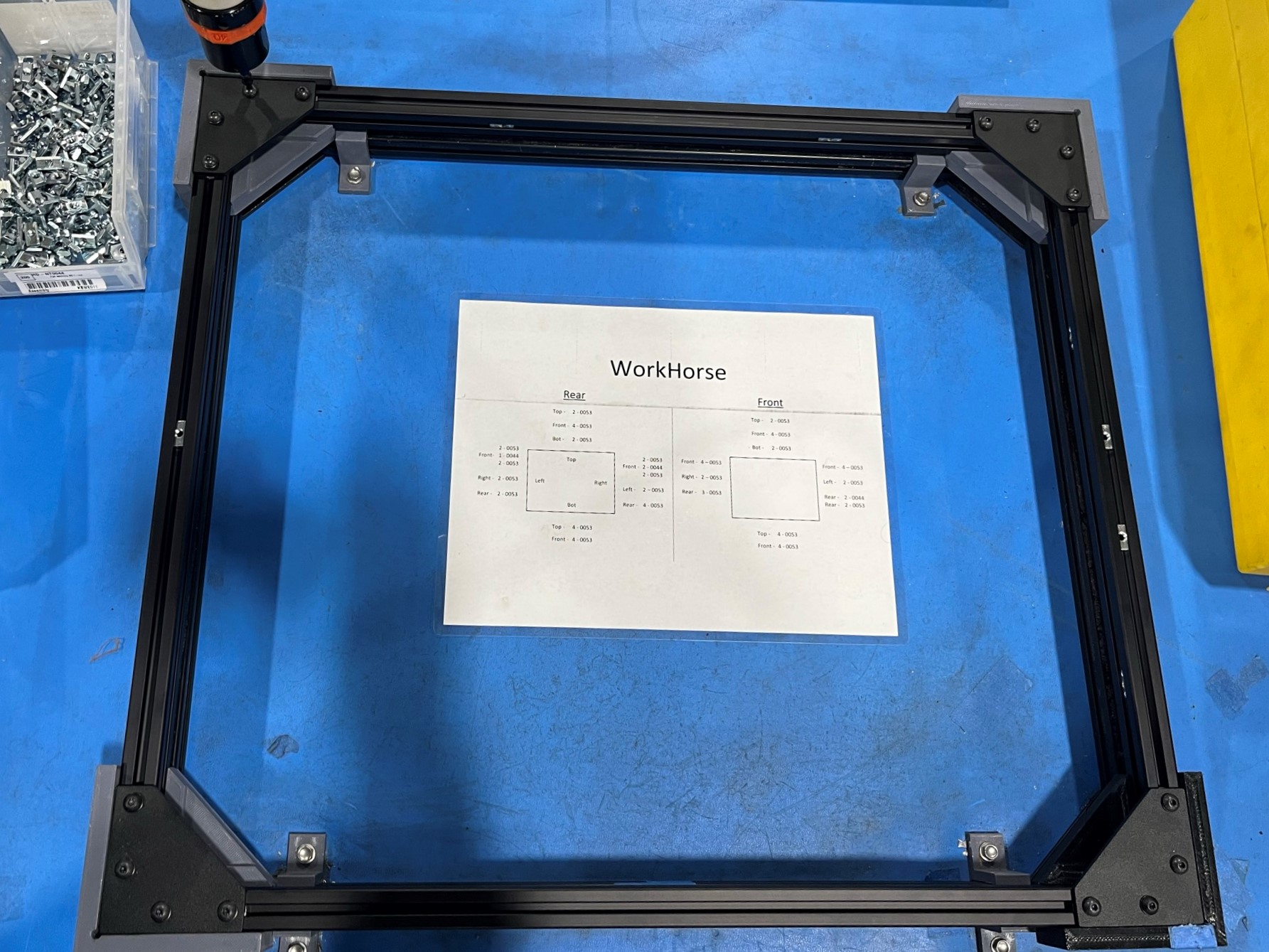
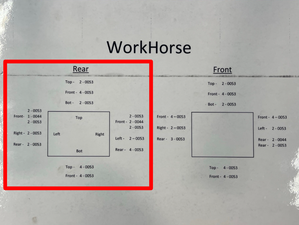
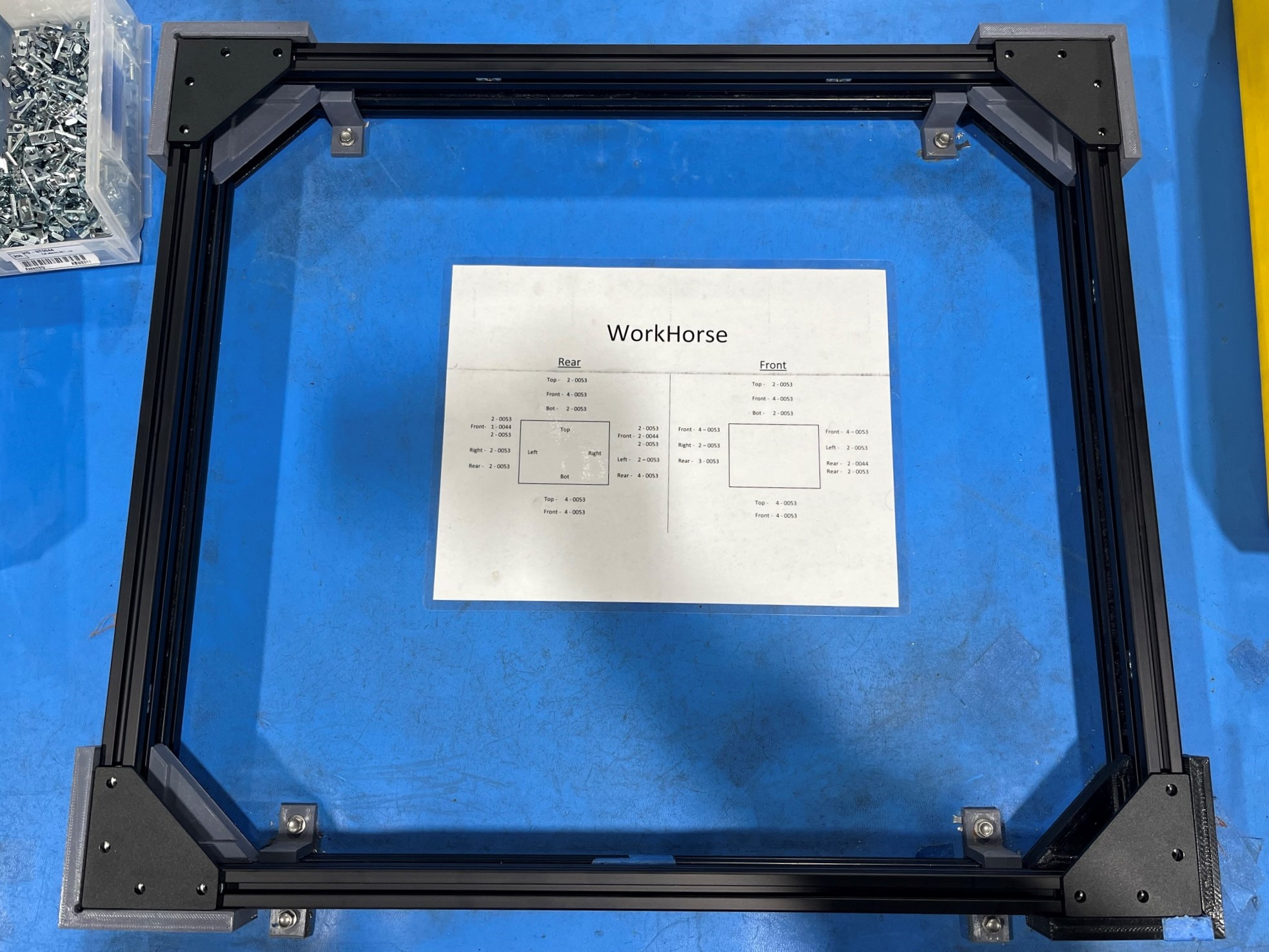
Follow the Front T-slot nut guide on the WorkHorse printout located at the frame sub-assembly work station.
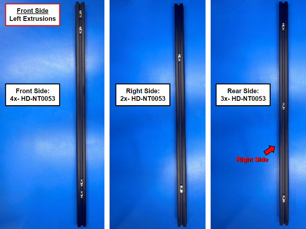
Follow the Front Side, Left Extrusion guide slide 9x M5 T-slot nuts [HD-NT0053] into 1x T-slot extrusion 500mm [HD-EX0062]
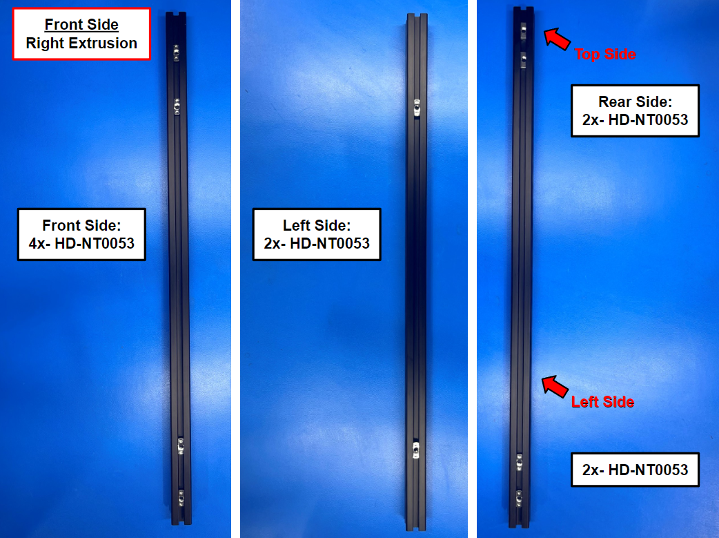
Follow the Front Side, Right Extrusion guide slide 8x M5 T-slot nuts [HD-NT0053] and 2x post assembly T-slot nuts [HD-NT0044] into 1x T-slot extrusion 500mm [HD-EX0062]
Then take the front side left and right extrusions and place them in the fixture mounted to the work station. Make sure the right extrusion has the 2x [HD-NT0044] on top!
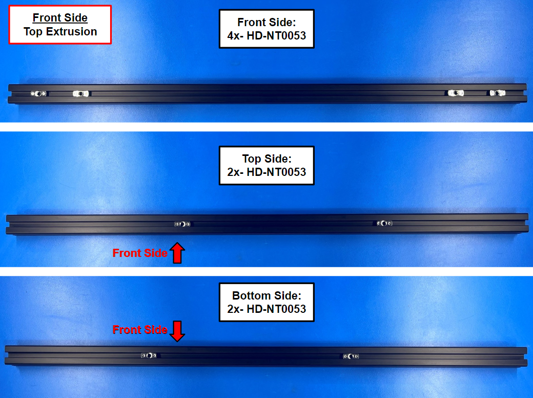
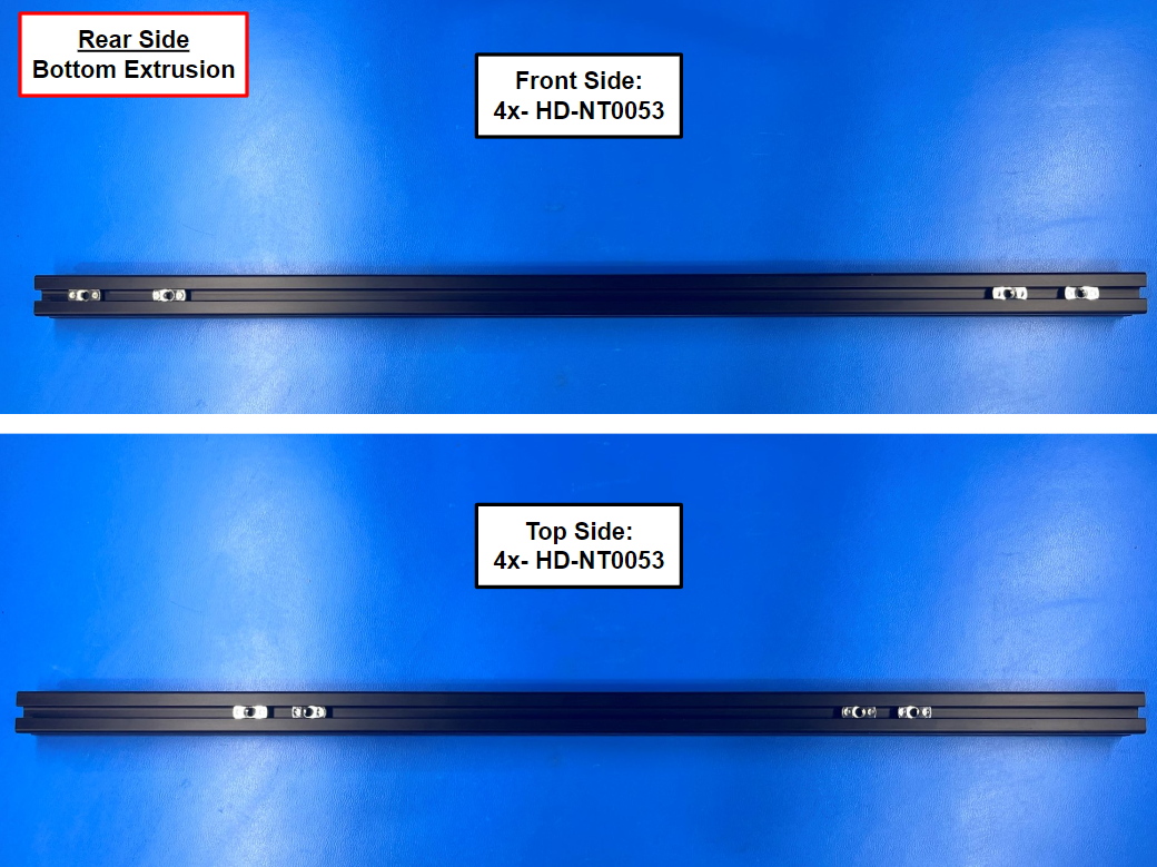
Follow the Front Side, Top Extrusion guide slide 8x M5 T-slot nuts [HD-NT0053] into 1x T-slot extrusion 530mm [HD-EX0086]
Follow the Front Side, Bottom Extrusion guide using 8x M5 T-slot nuts [HD-NT0053]
Then take the front side top and bottom extrusions and place them in the fixture mounted to the work station.


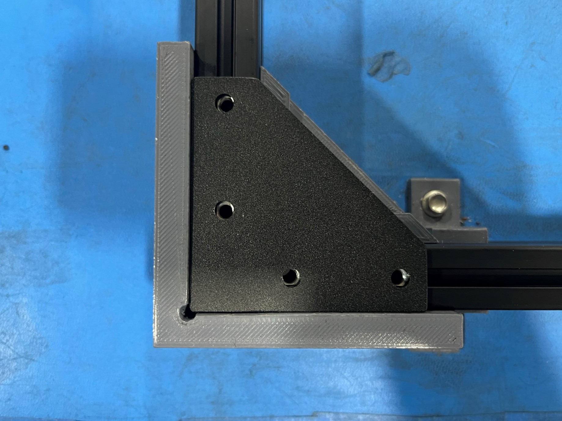
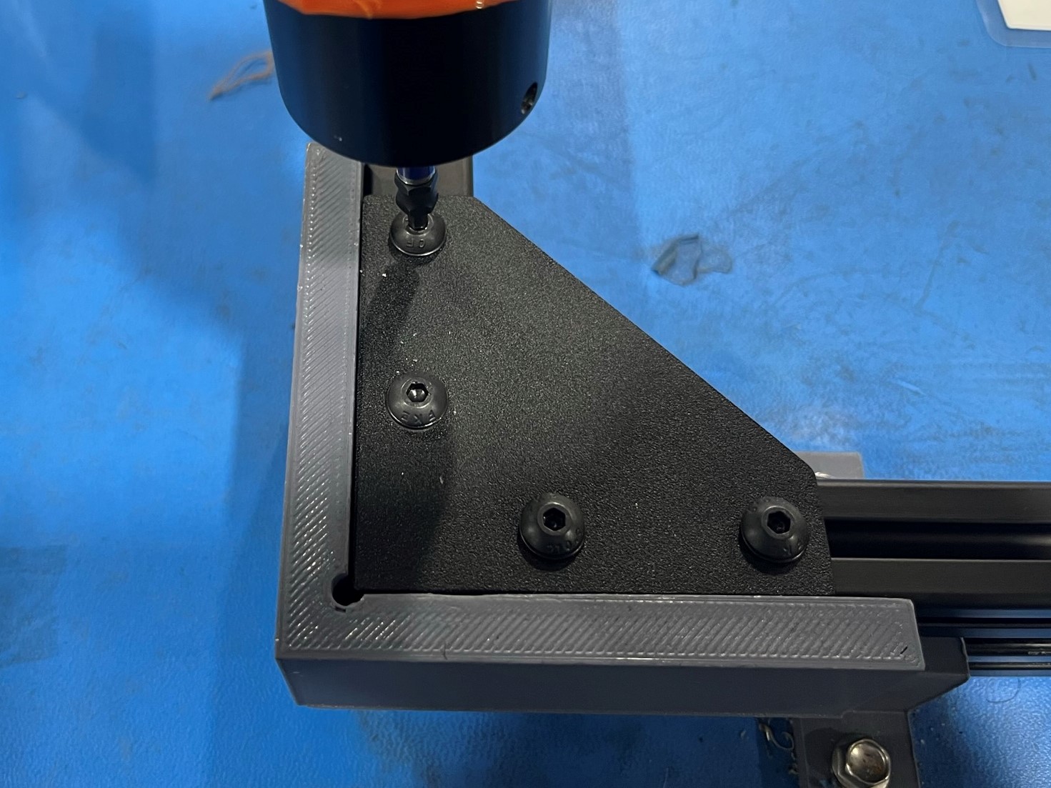
Place a corner bracket [PP-FP0152] over the corner of two extrusions and align the end two T-slot nuts on each extrusion with the four holes in the corner bracket.
Then repeat for the other three corners.
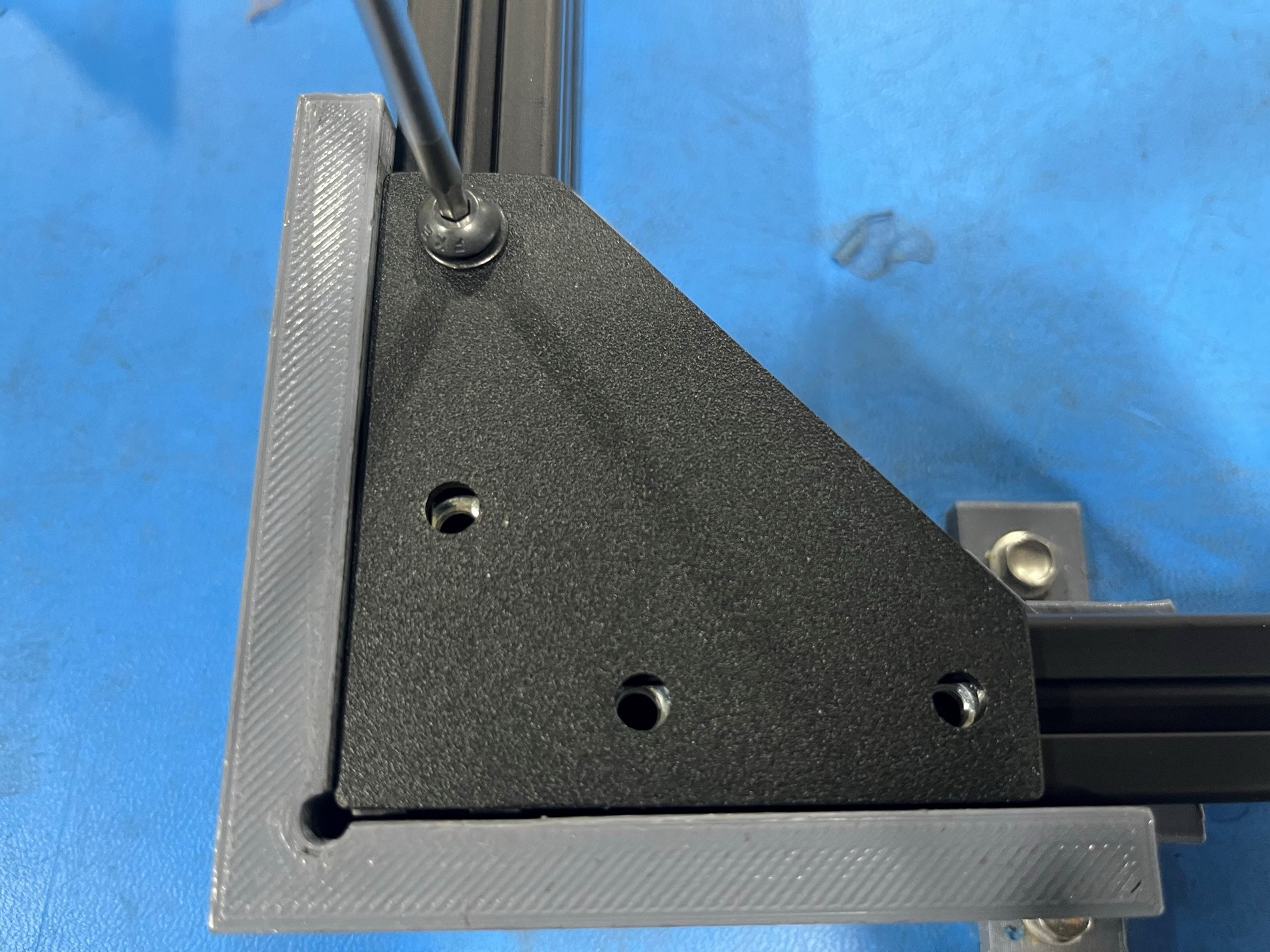
Now use 1x M5x10 BHCS [HD-BT0073] with a M5 washer [HD-WA0040] and loosely secure the corner bracket to the extrusion.
Then repeat for the other 15 holes in the corner brackets.
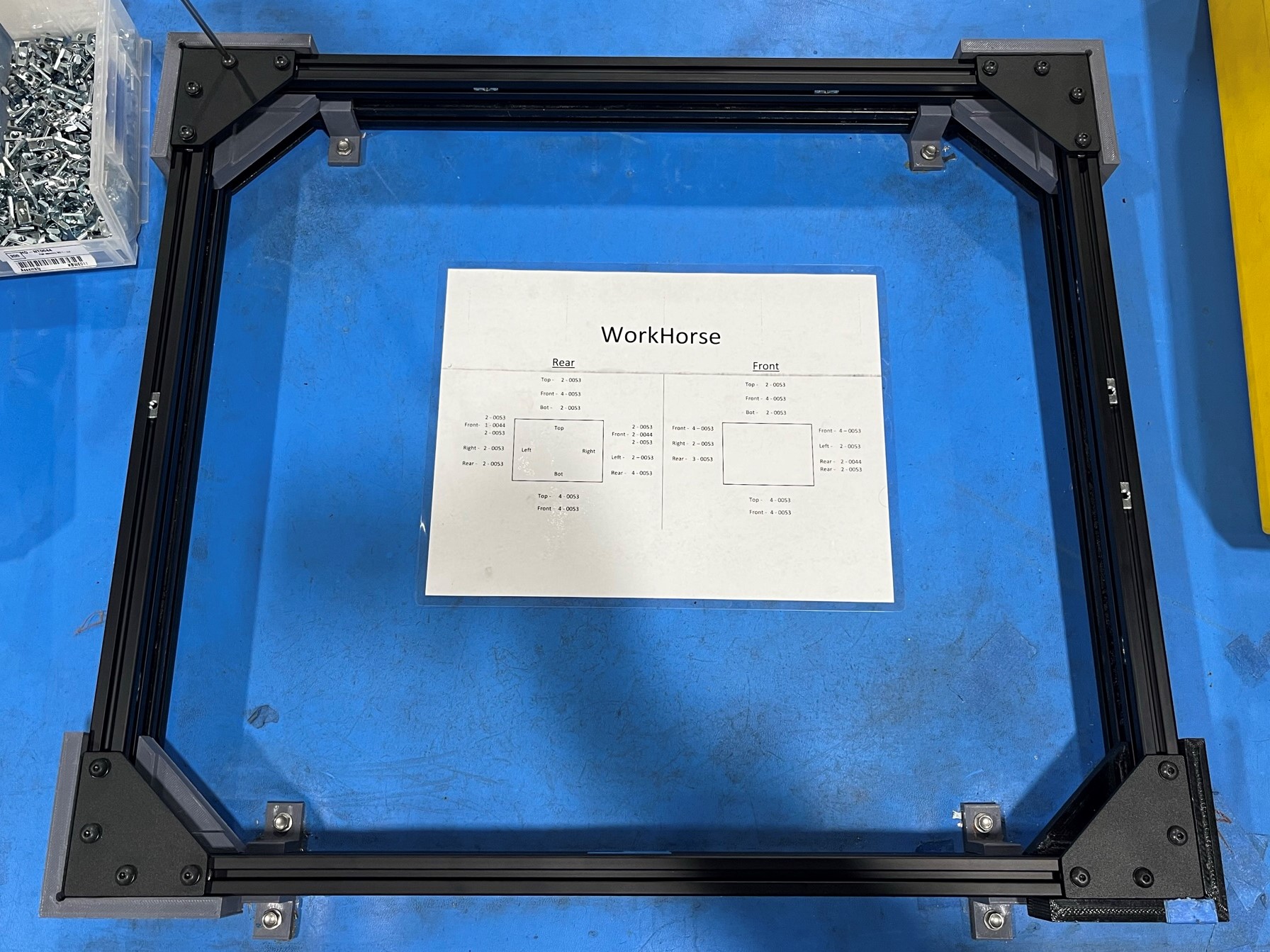

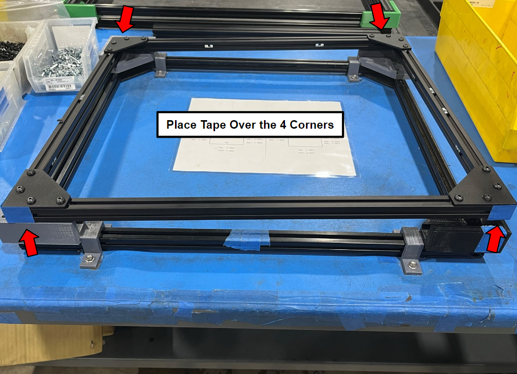
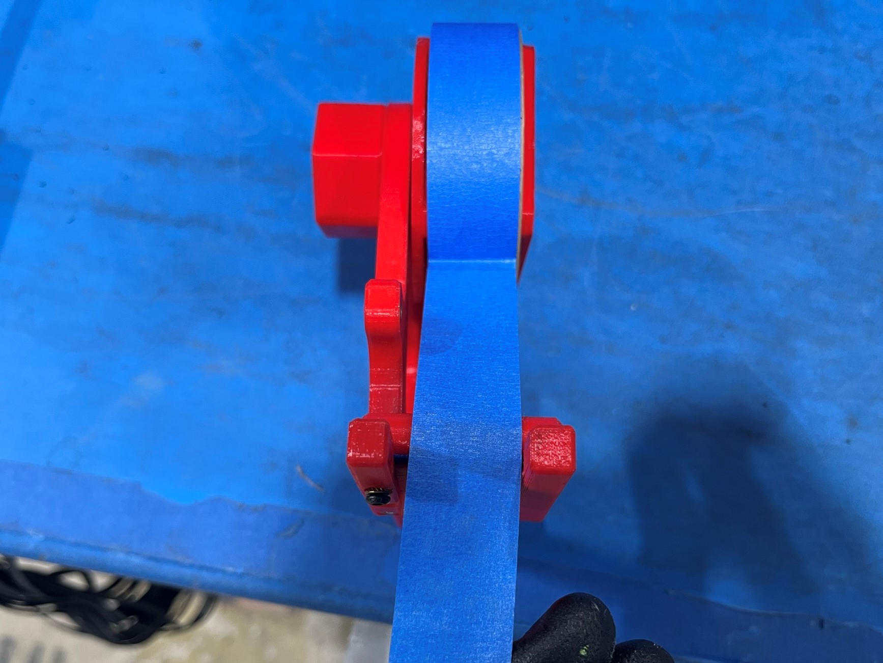
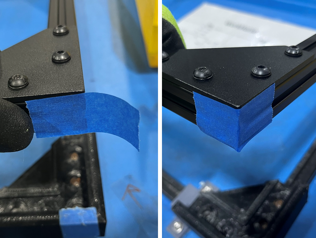
Place the blue tape around each corner to keep the T-slot nuts from sliding out of the extrusions.
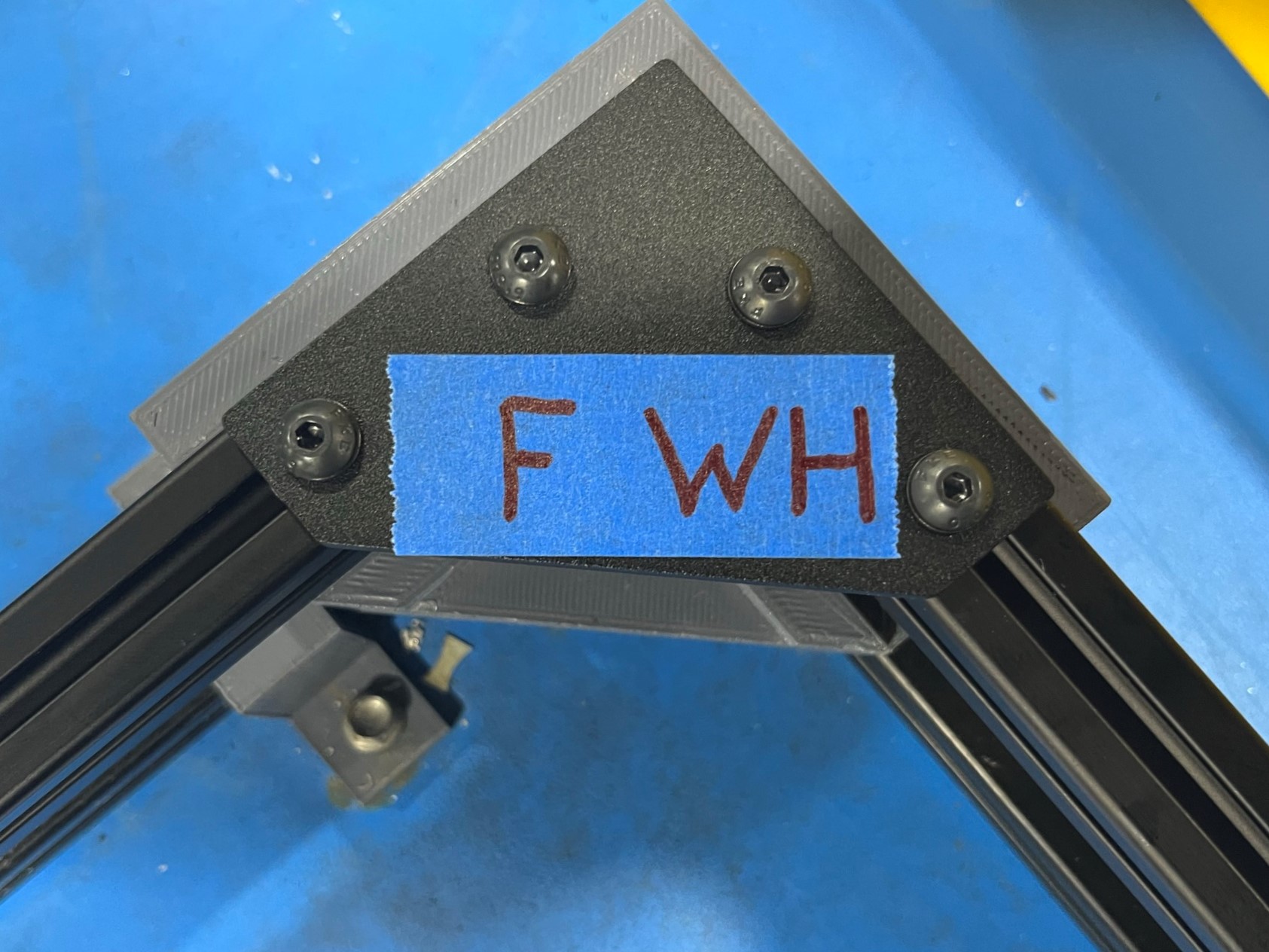
Then tape the top right corner bracket and use the marker at the work station to write F WH

2x- [HD-EX0062] T-Slot Aluminum Extrusion 500mm
2x- [HD-EX0086] T-Slot Extrusion, Aluminum, 530mm
16x- [HD-BT0073] M5x10 BHCS, Black-Oxide
3x- [HD-NT0044] Post Assembly M5 T-Slot Nuts
34x- [HD-NT0053] M5 T-Slot Nuts
16x- [HD-WA0040] M5 Washers
4x- [PP-FP0152] Corner Bracket

Follow the Rear T-slot nut guide on the WorkHorse printout located at the frame sub-assembly work station.
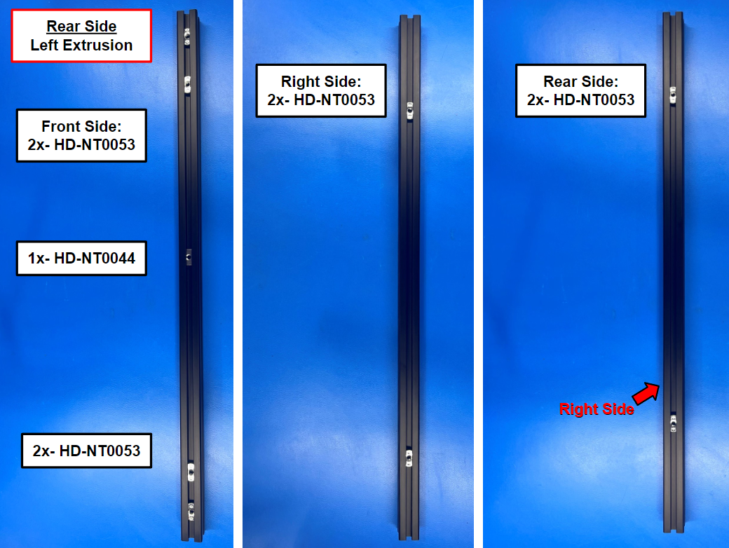
Follow the Rear Side, Left Extrusion guide using 8x M5 T-slot nuts [HD-NT0053] and 1x post assembly T-slot nuts [HD-NT0044]
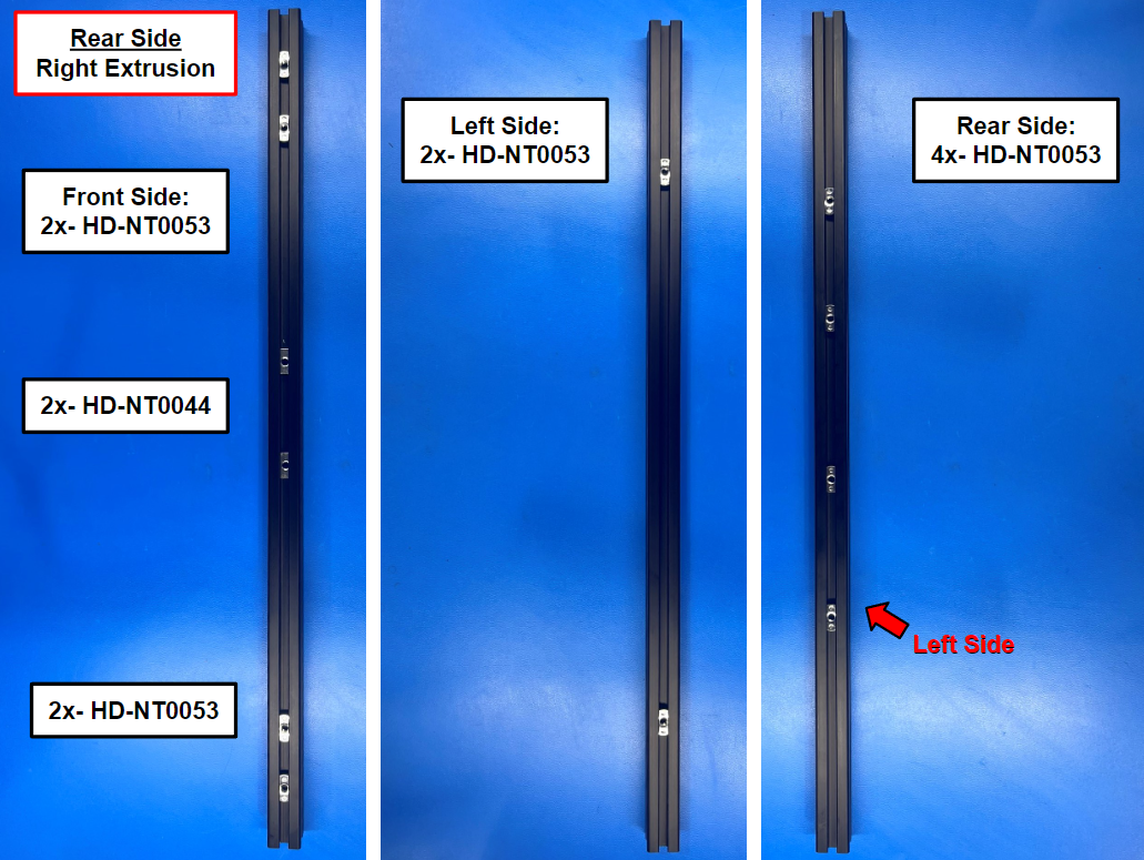
Follow the Rear Side, Right Extrusion guide using 10x M5 T-slot nuts [HD-NT0053] and 2x post assembly T-slot nuts [HD-NT0044]
Then take the rear side left and right extrusions and place them in the fixture mounted to the work station.
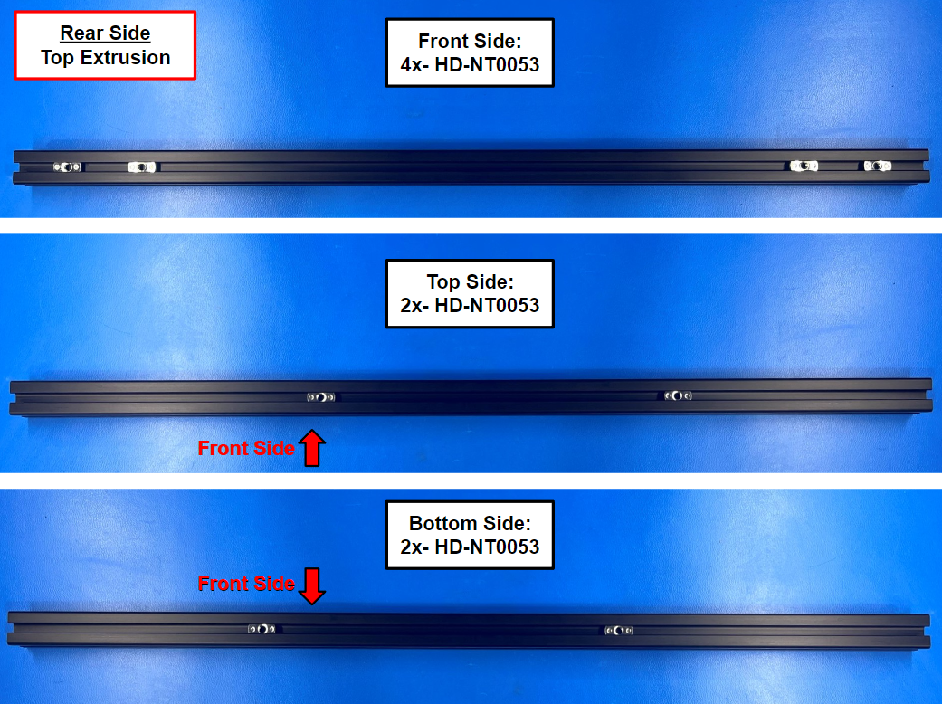
Follow the Rear Side, Top Extrusion guide using 8x M5 T-slot nuts [HD-NT0053]
Follow the Rear Side, Bottom Extrusion guide using 8x M5 T-slot nuts [HD-NT0053]
Then take the rear side top and bottom extrusions and place them in the fixture mounted to the work station.


Repeat the assembly process for the rear side.
Place a corner bracket [PP-FP0152] over the corner of two extrusions and align the end two T-slot nuts on each extrusion with the four holes in the corner bracket.
Then repeat for the other three corners.
Now use 1x M5x10 BHCS [HD-BT0073] with a M5 washer [HD-WA0040] and loosely secure the corner bracket to the extrusion.
Then repeat for the other 15 holes in the corner brackets.


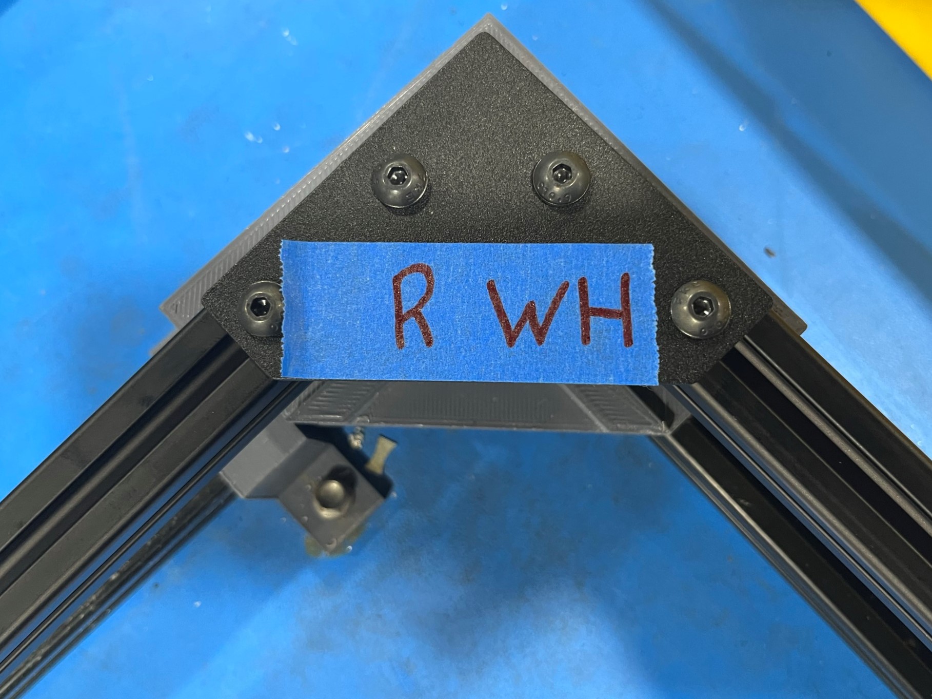
Place the blue tape around each corner to keep the T-slot nuts from sliding out of the extrusions.
Then tape the top right corner bracket and use the marker at the work station to write R WH