Open HardwareAssembly Instructions
Guides for installation and assembly of the LulzBot line of products made by FAME 3D LLC.
Guides for installation and assembly of the LulzBot line of products made by FAME 3D LLC.
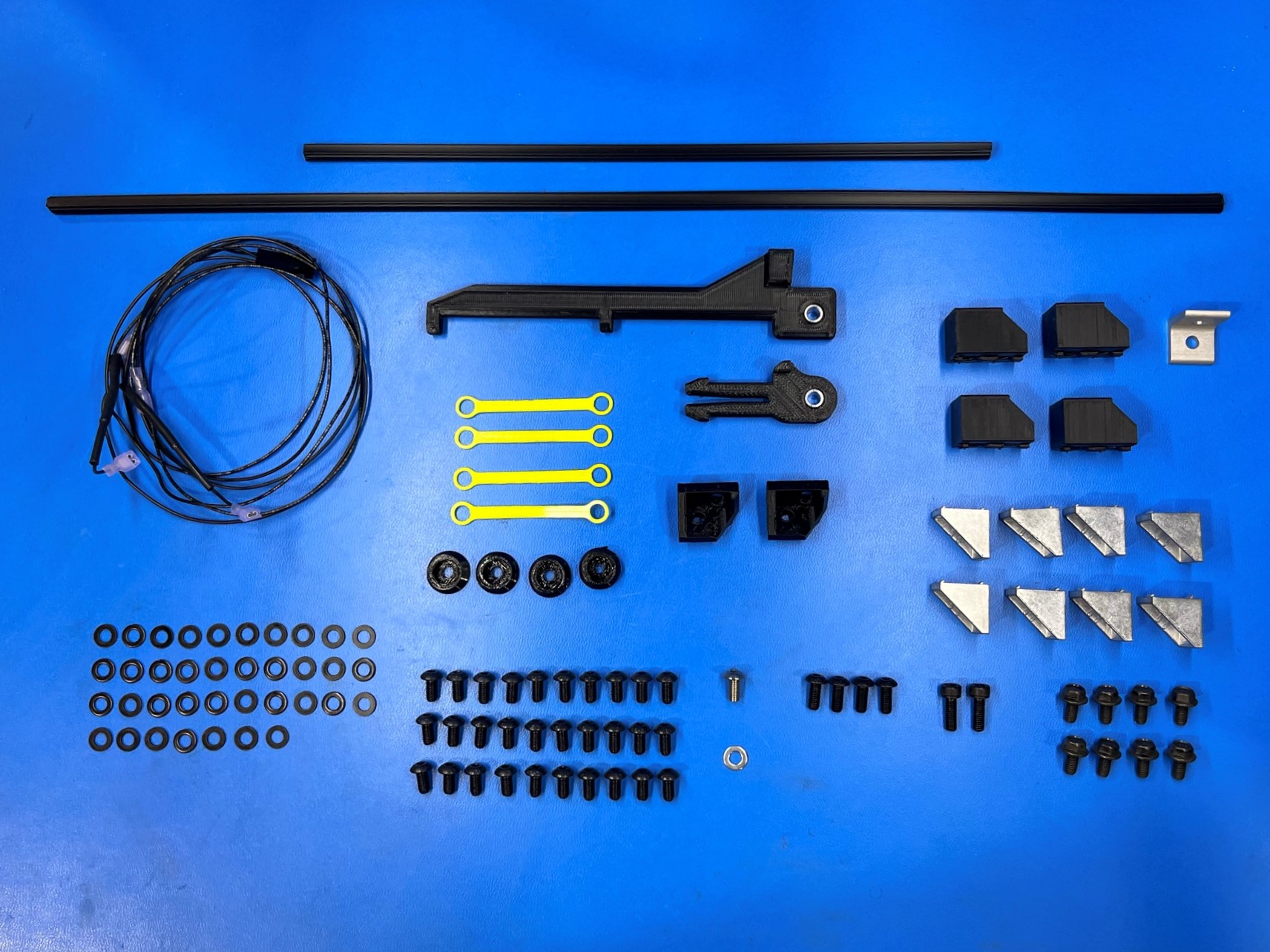
1x- [AS-PR0150] T-Slot Dust Cover 300mm
1x- [AS-PR0151] T-Slot Dust Cover 510mm
1x- [EL-HR0142] TAZ Pro/WE, Z Endstop Harness
2x- [HD-BT0049] M5x14 SHCS, Black-Oxide
30x- [HD-BT0073] M5x10 BHCS, Black-Oxide
4x- [HD-BT0158] M5x12 BHCS, Black-Oxide
1x- [HD-BT0225] M5x10 BHCS, SST
8x- [HD-BT0250] M5x10 HHCS Flanged, Black-Oxide
8x- [HD-EX0090] 90 Degree Corner Bracket 2 Hole
1x- [HD-EX0092] 2 Hole Inside Corner Bracket
1x- [HD-WA0007] M5 Washer, Zinc
37x- [HD-WA0040] M5 Washer
1x- [PP-GP0218] Tippy Feed Tube Holder
1x- [PP-GP0406] Dual Spool Arm, Pro/WE
4x- [PP-GP0409] Frame Foot, Pro/WE
2x- [PP-GP0411] Electronics Chassis Mount
4x- [PP-GP0432] Bed Mount Chassis, Pro/WE
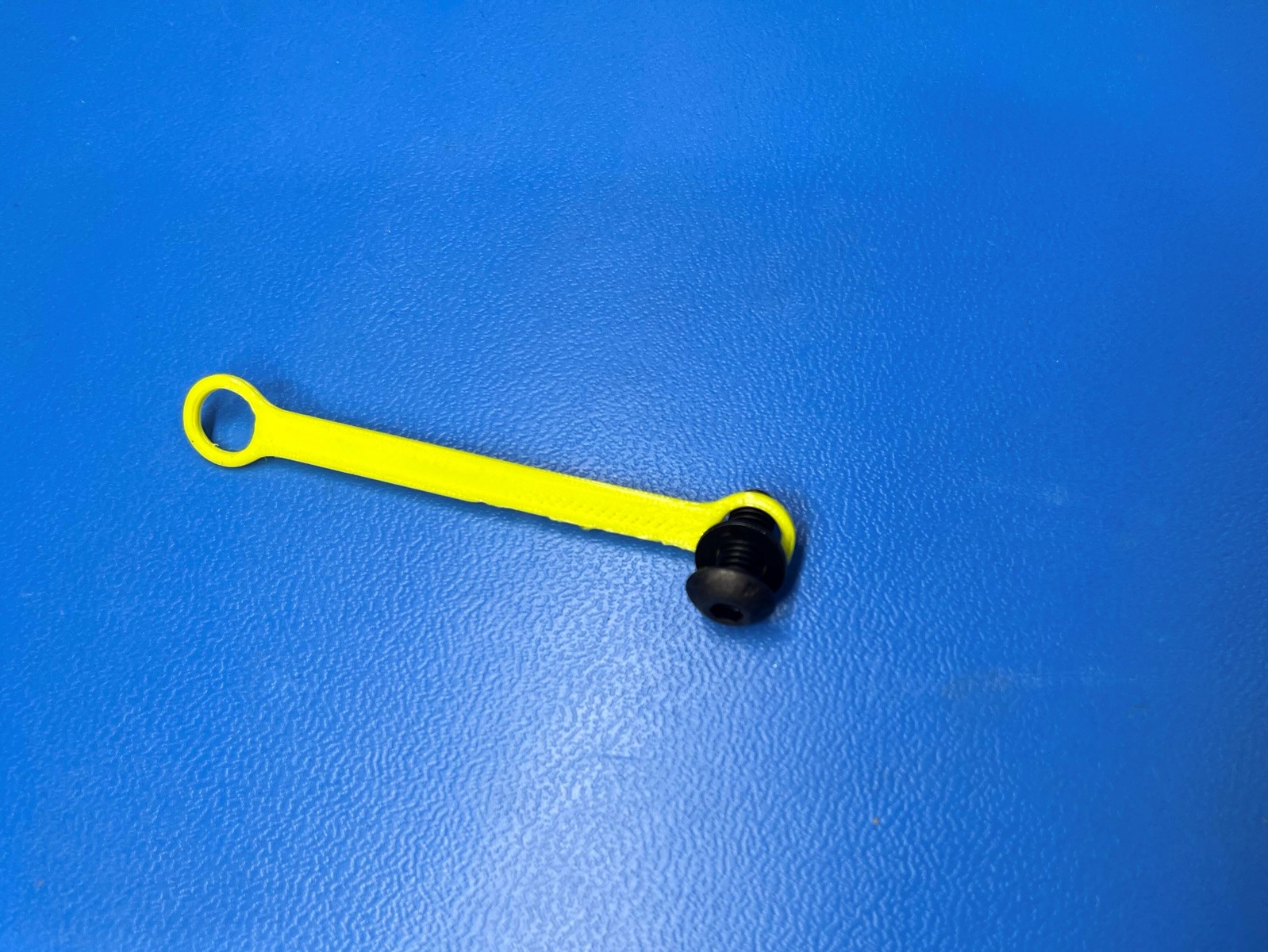
4x- [PP-GP0448] Thumbscrew Leash, Flexible WE
Frame Sub-Assembly
X End Left Assembly
X End Right Assembly
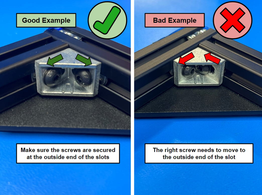
Take the front frame and align the T-slot nuts with the corner of the frame.
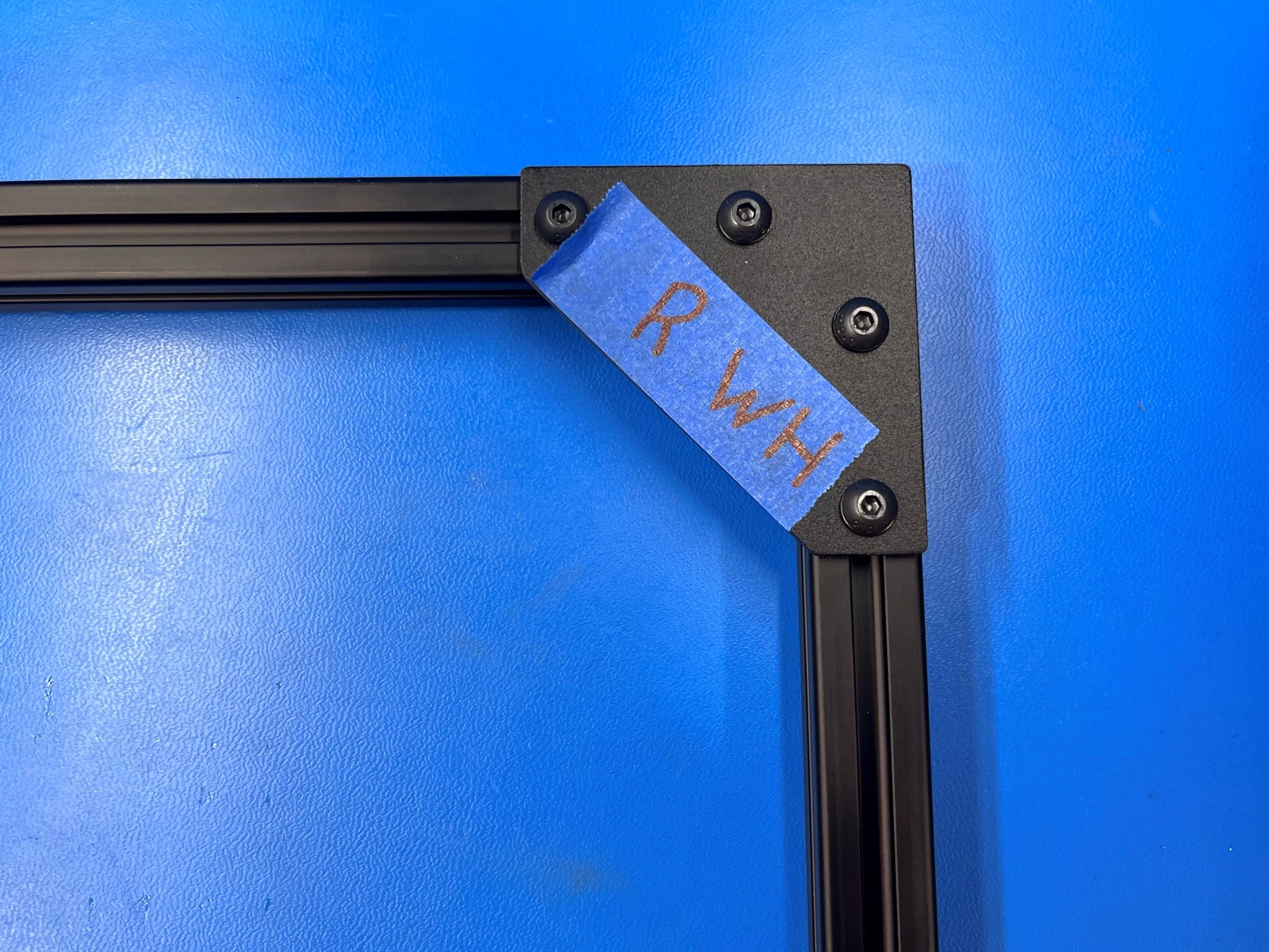
Using 1x 90 degree corner bracket [HD-EX0090], 2x M5 x 10 BHCS [HD-BT0073] and 2x M5 washers [HD-WA0040] attach the corner bracket to the corner of the frame.
Repeat the process for the other three corners on the front frame.
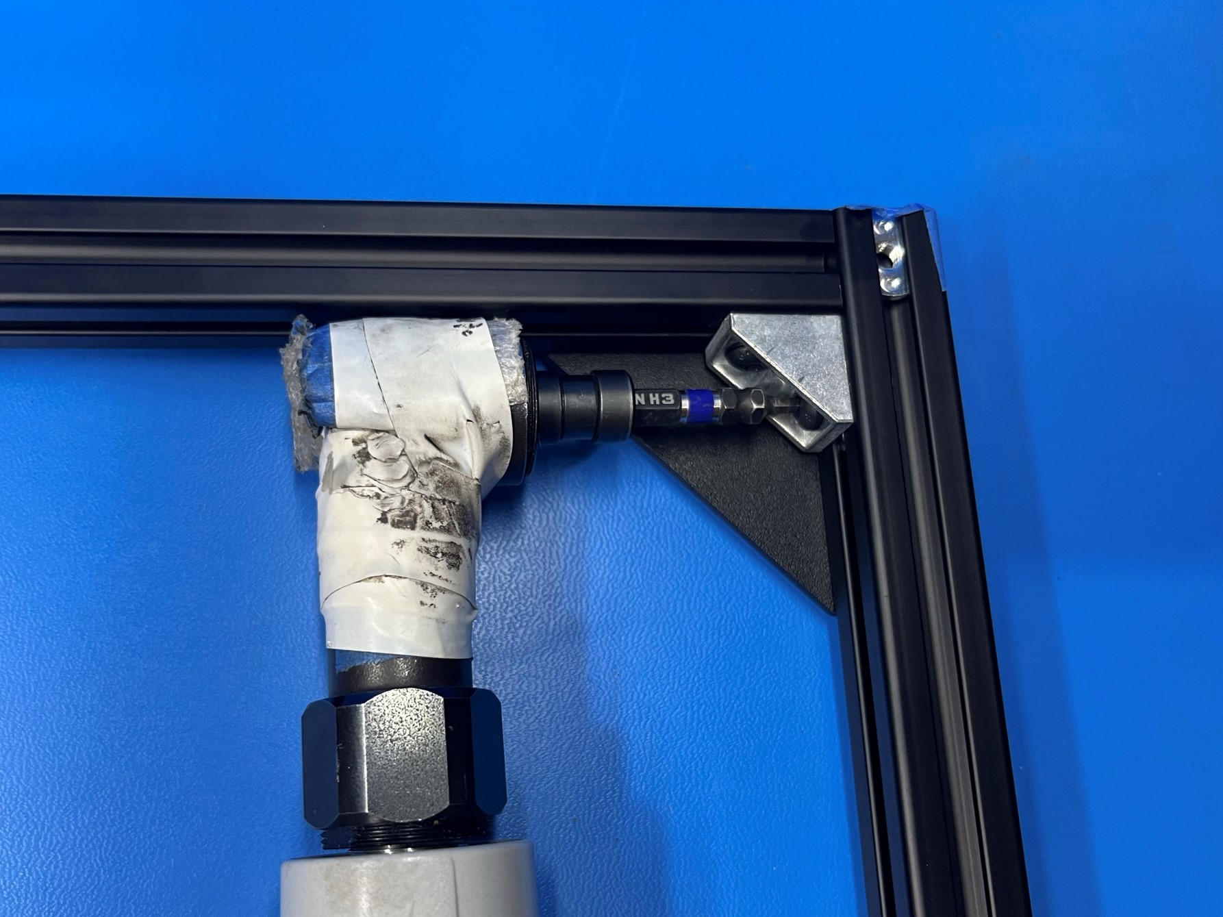
Then using the torque driver, torque all the screws securing the corner bracket.
Repeat the process for the rear frame.


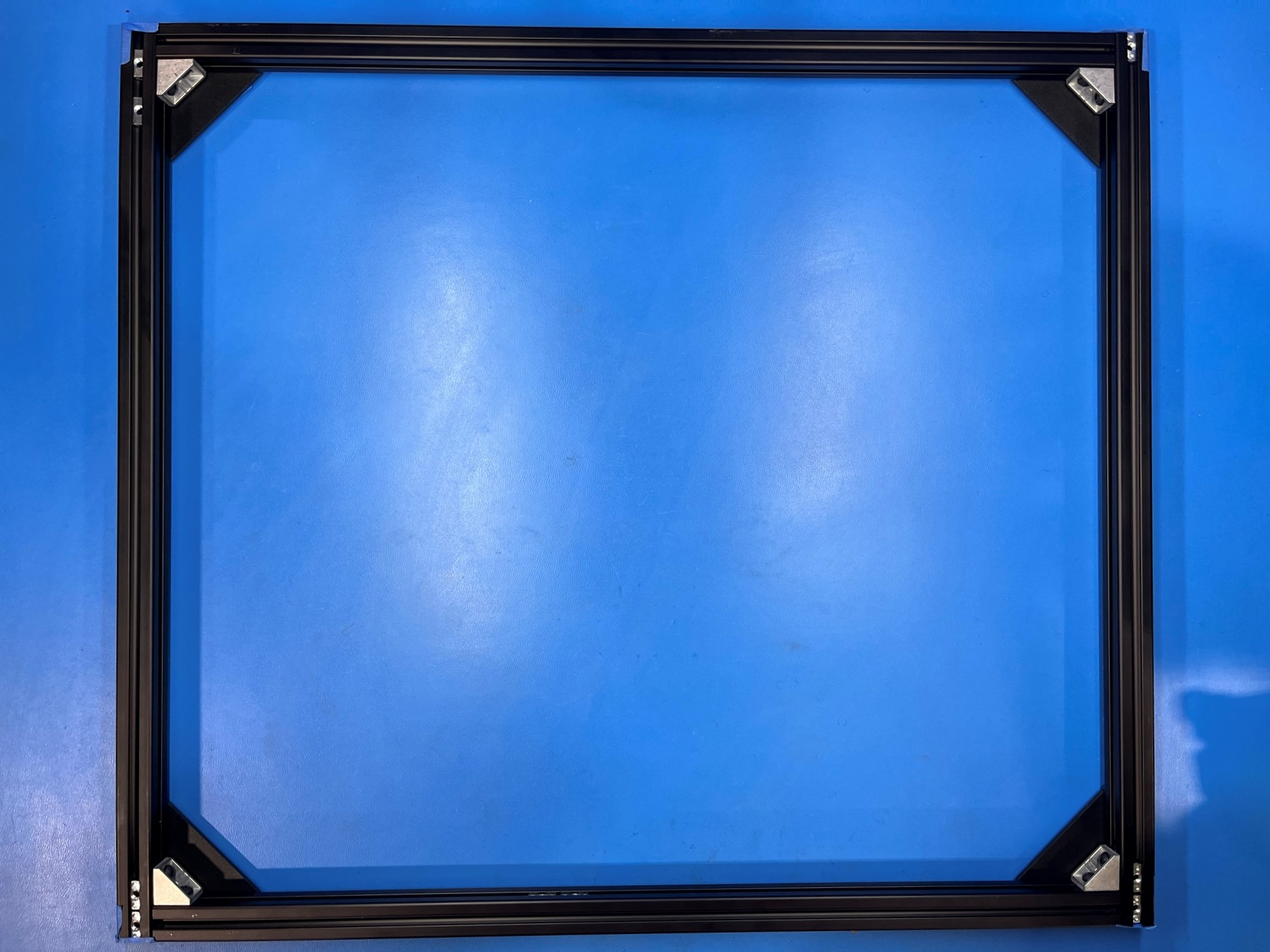

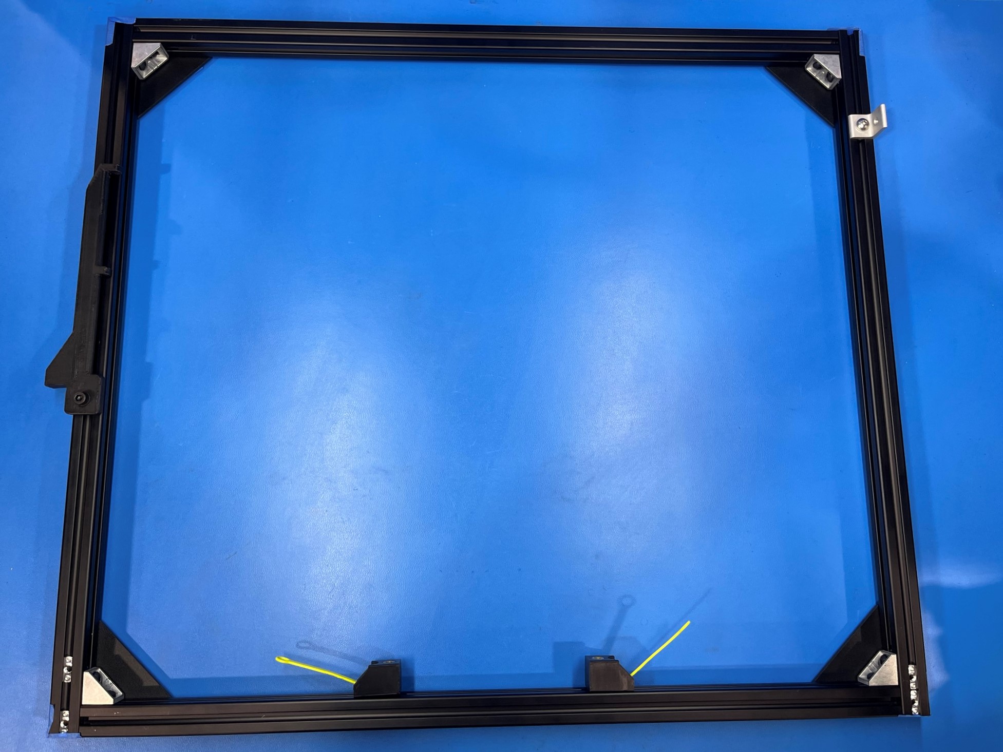
Place the front frame sub-assembly on the table with the black corner brackets resting on the table.
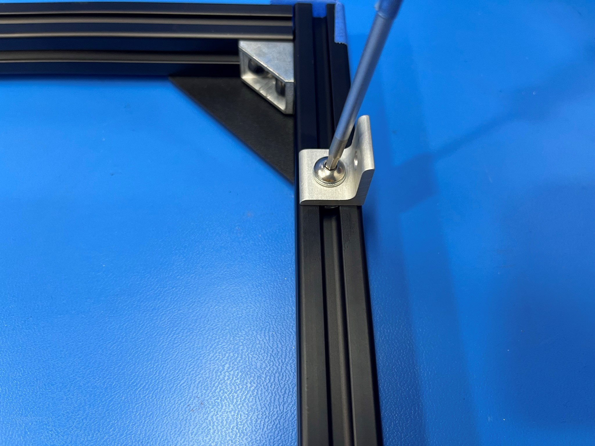
Then use 1x M5x10 BHCS SST [HD-BT0225] to secure the aluminum corner bracket to the top most T-slot nut on the right extrusion.
Then use 1x M5x14 SHCS [HD-BT0049] with a M5 washer [HD-WA0040] to attach the dual spool arm to the left extrusion. Be sure to use the dual spool arm spacer to set the distance from the bottom of the front frame and the flat side of the spool arm. Make sure there is one T-slot nut above the spool arm and two below it.
Rotate the front frame so that it's resting on the bottom extrusion.
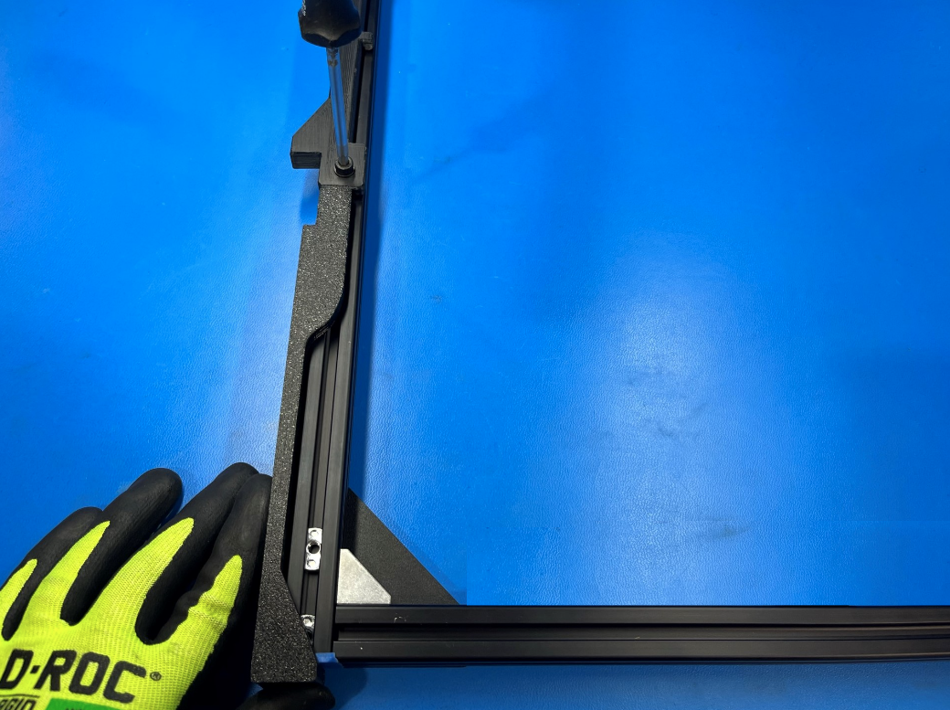
Then take 1x M5x12 BHCS [HD-BT0158] and slide a 5M washer [HD-WA0040] around it followed by a thumbscrew leash [PP-GP0448].
Now follow [reference#1] and use the bolt, washer and thumbscrew leash to secure the bed mount chassis [PP-GP0432] to the inside of the bottom extrusion.
Repeat for the second bed mount chassis, make sure the thumbscrew leashes are points towards the outside of the frame.


Place the rear frame on the table with the black corner brackets facing up.
Then use 1x M5x14 SHCS [HD-BT0049] with a M5 washer [HD-WA0040] to attach the tippy feed tube holder to the left extrusion.
Now flip the rear frame over so that its resting on the black corner brackets.

Place the rear frame on the table with the black corner brackets resting on the table.
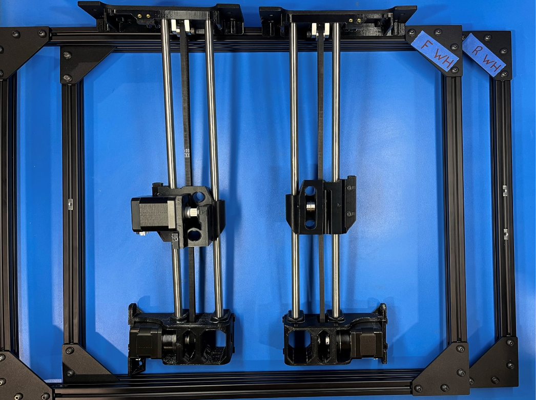
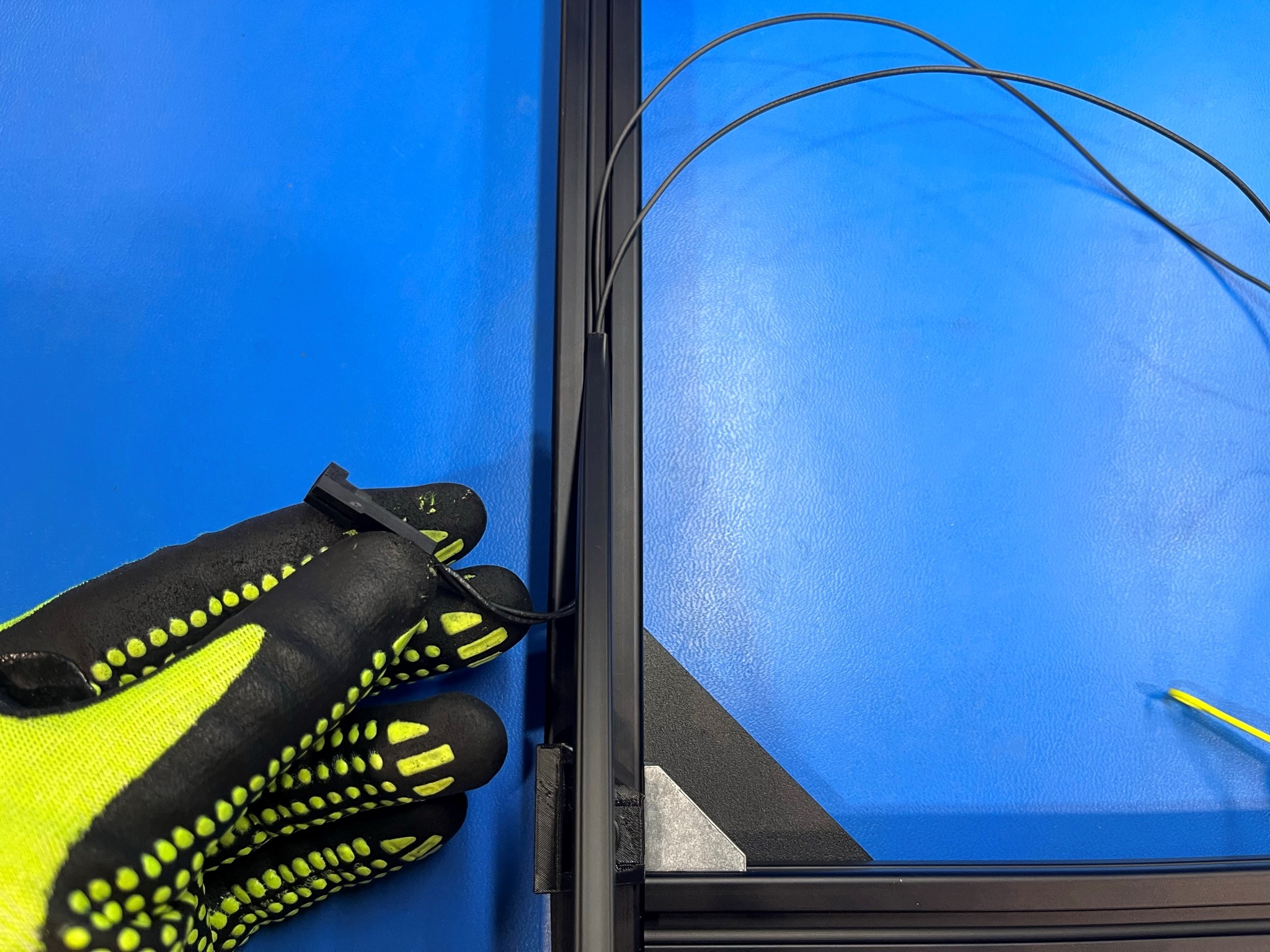
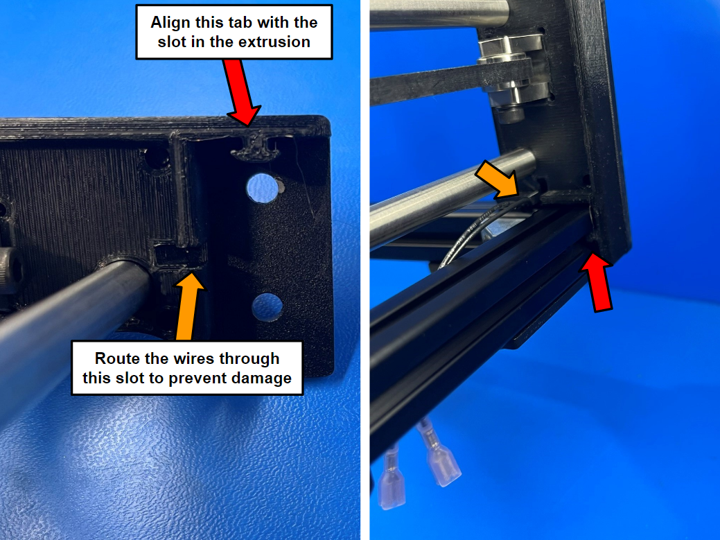
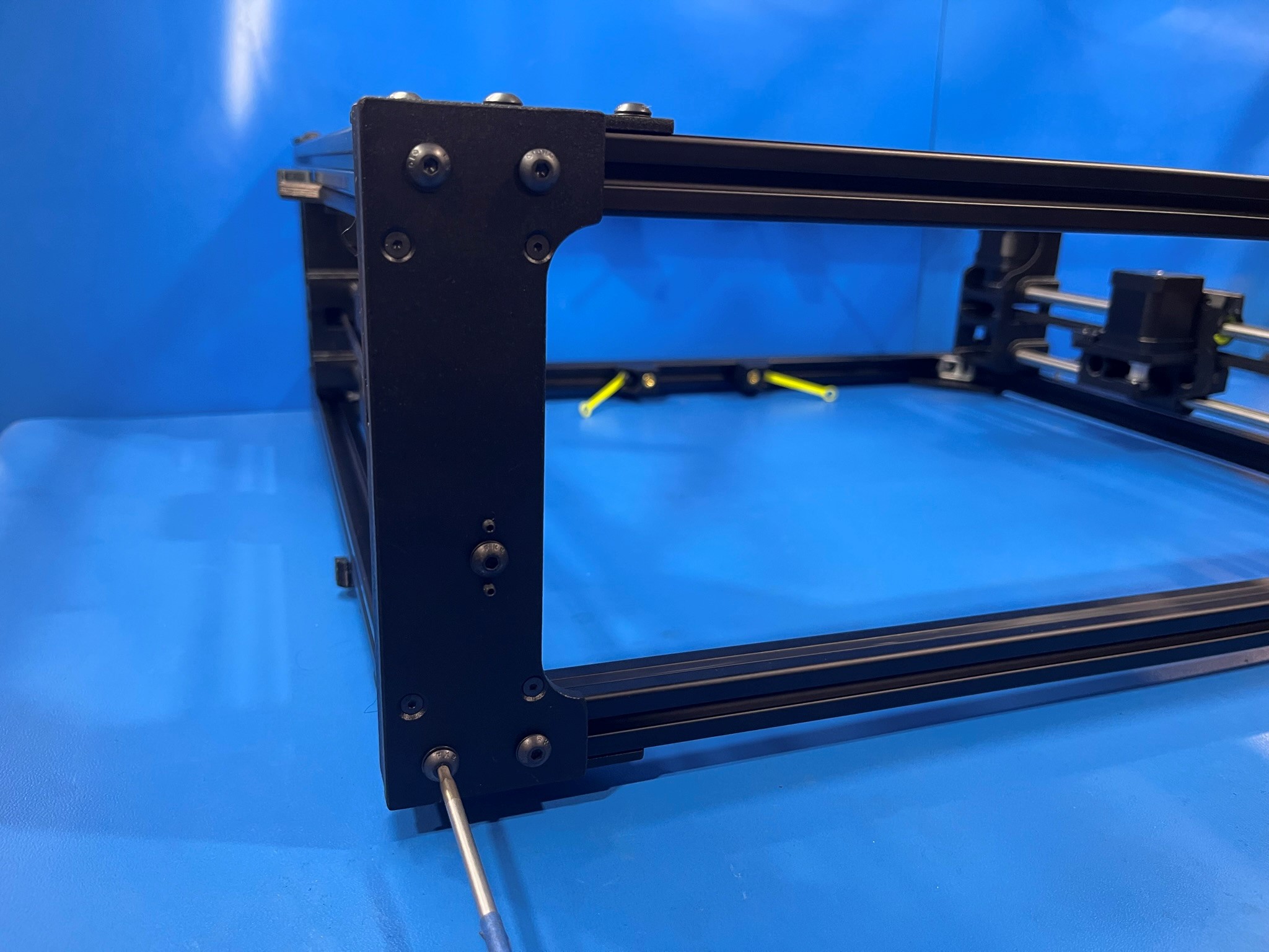
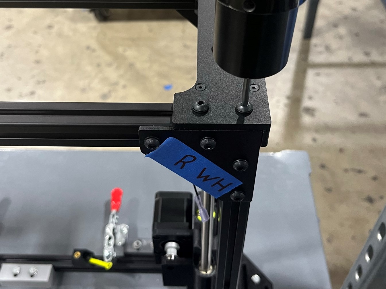
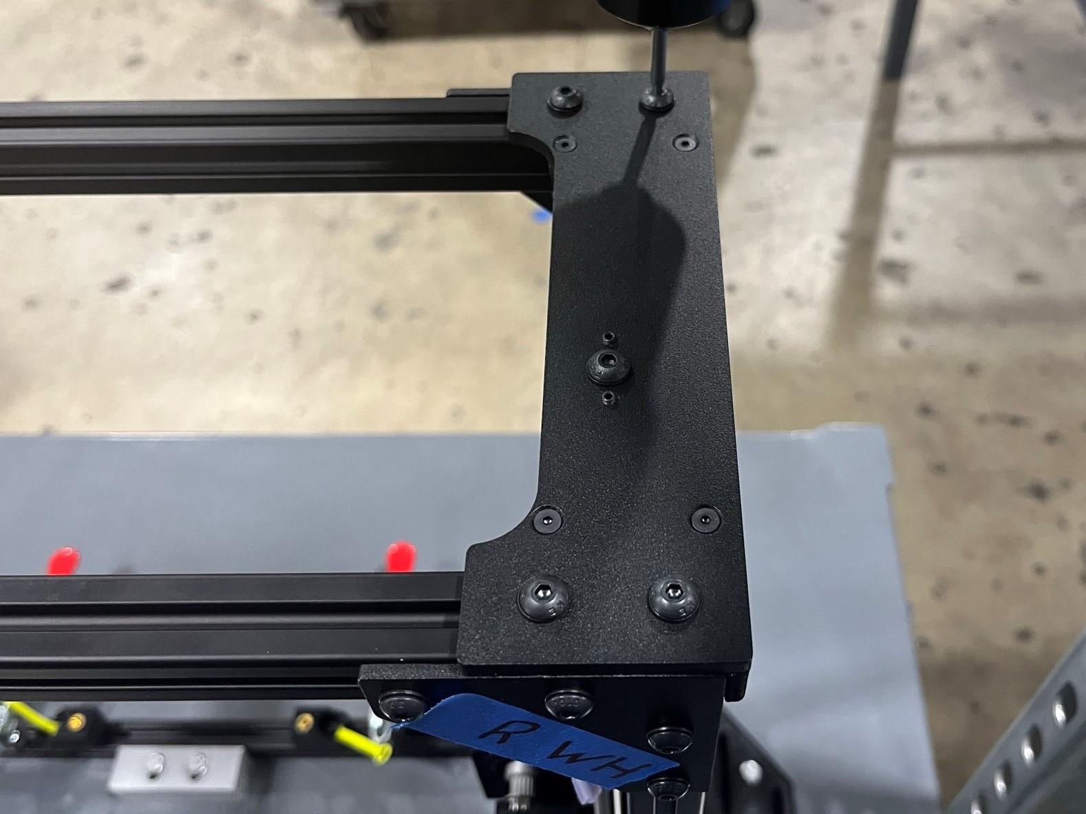
Take the X end right assembly and identify where the tabs for the extrusions are along with the slot for the wires before attaching it to the rear frame.
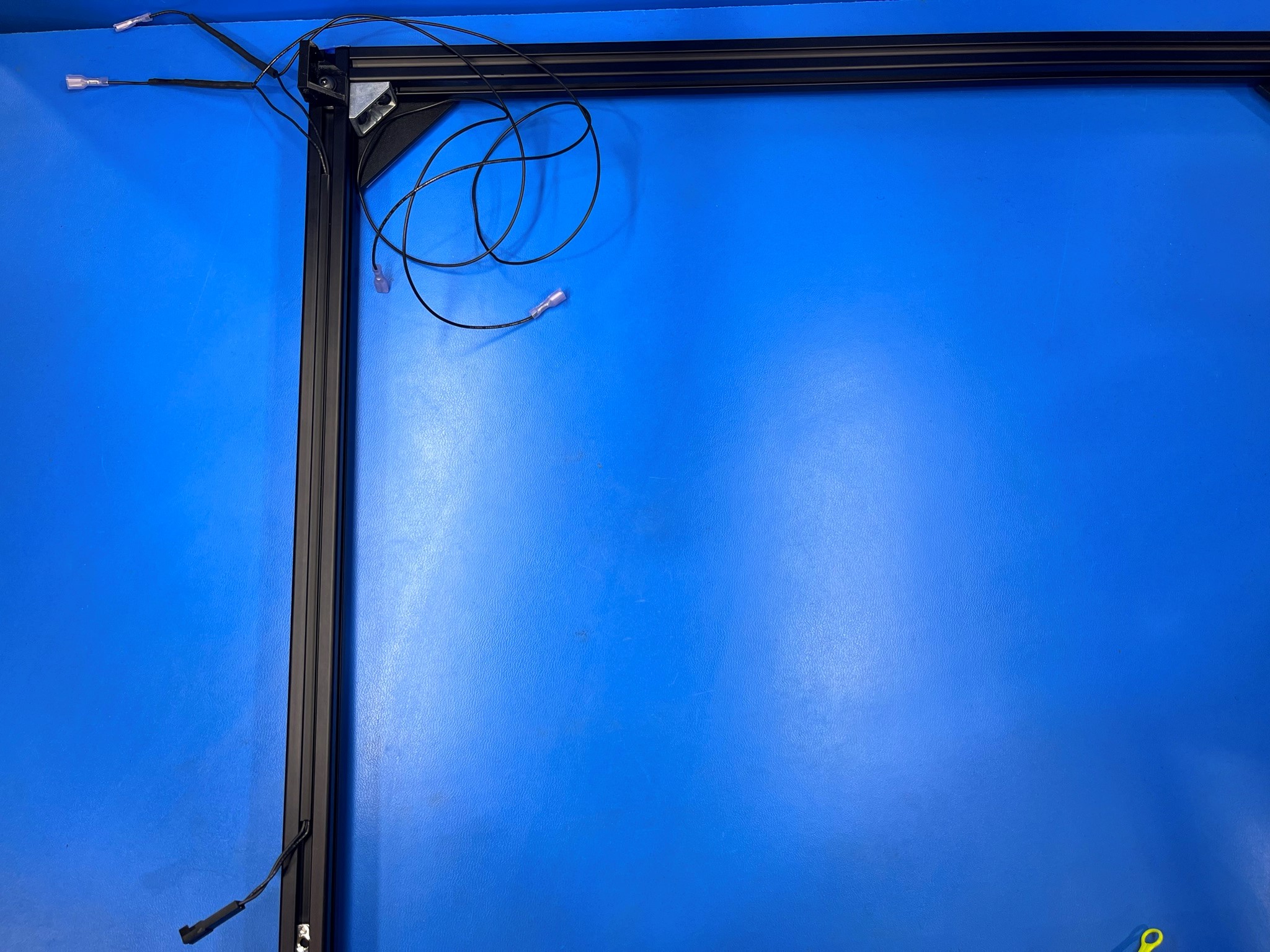
Now align the tab with the extrusion and slide it into the extrusion, make sure you are using the top right side of the rear frame and that you route the wires through the slot.
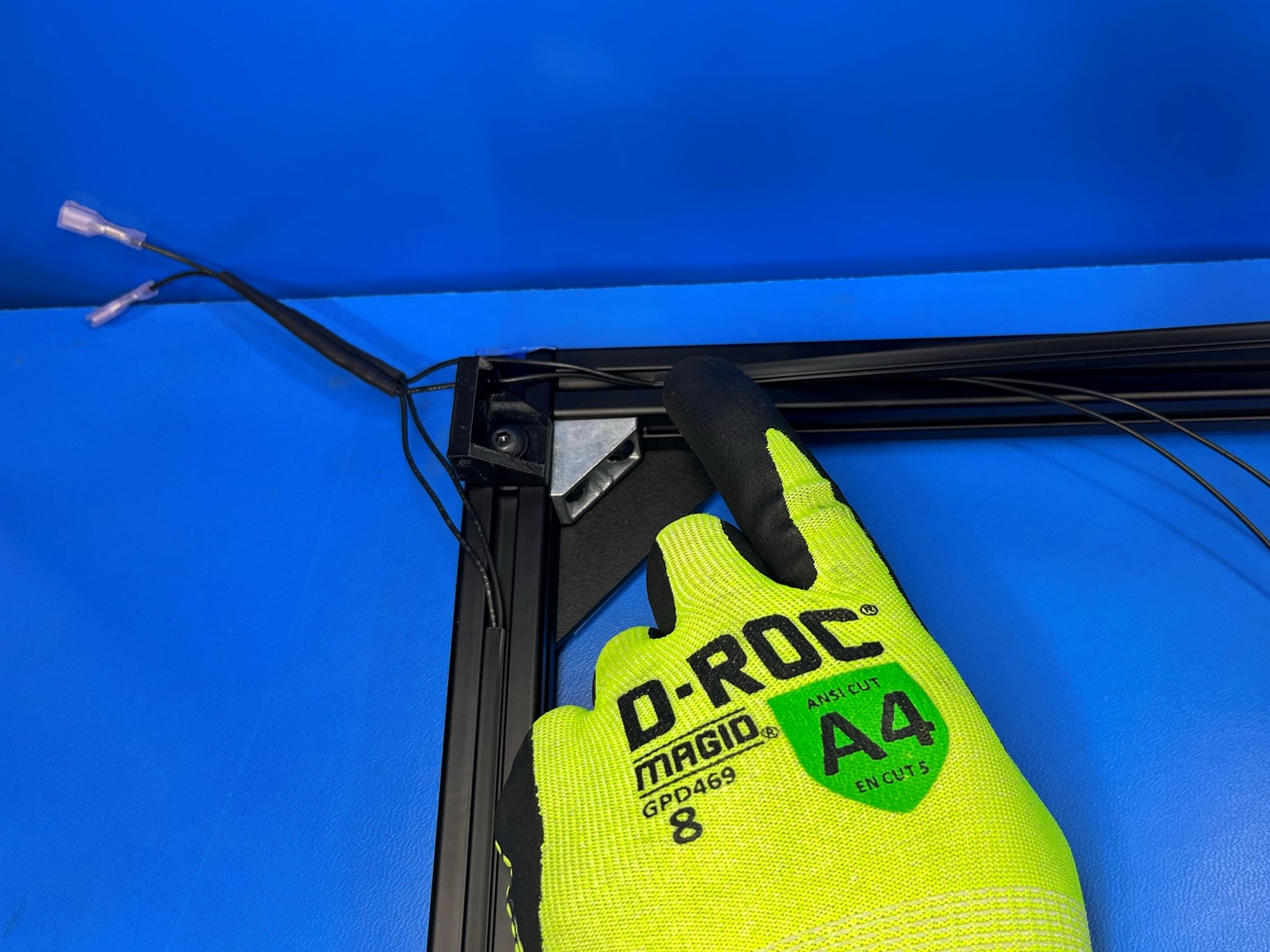
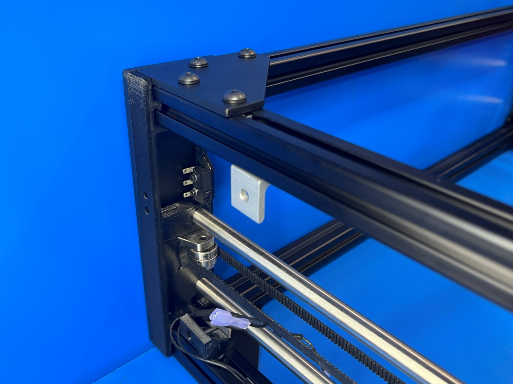
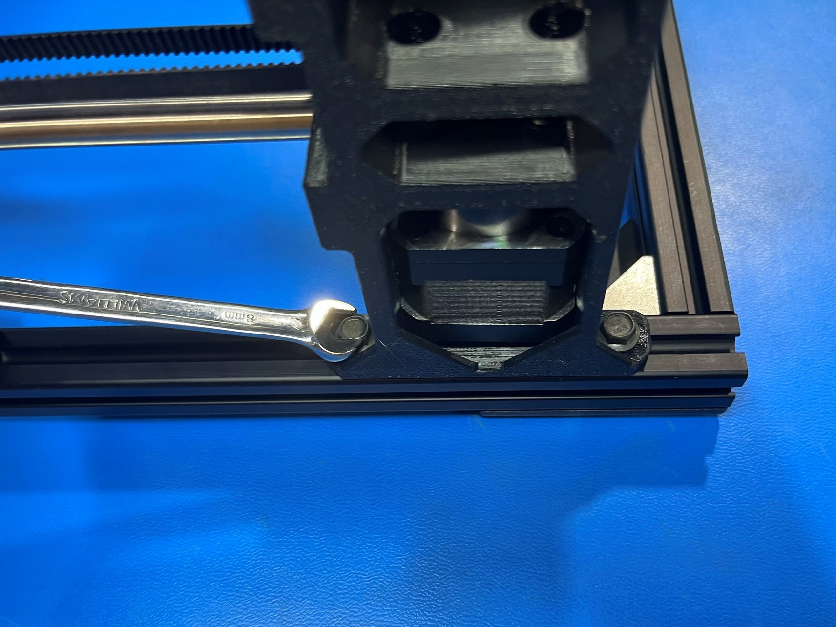
Then using 2x M5x10 HHCS [HD-BT0250] attach the bottom of the X end right assembly to the rear frame.
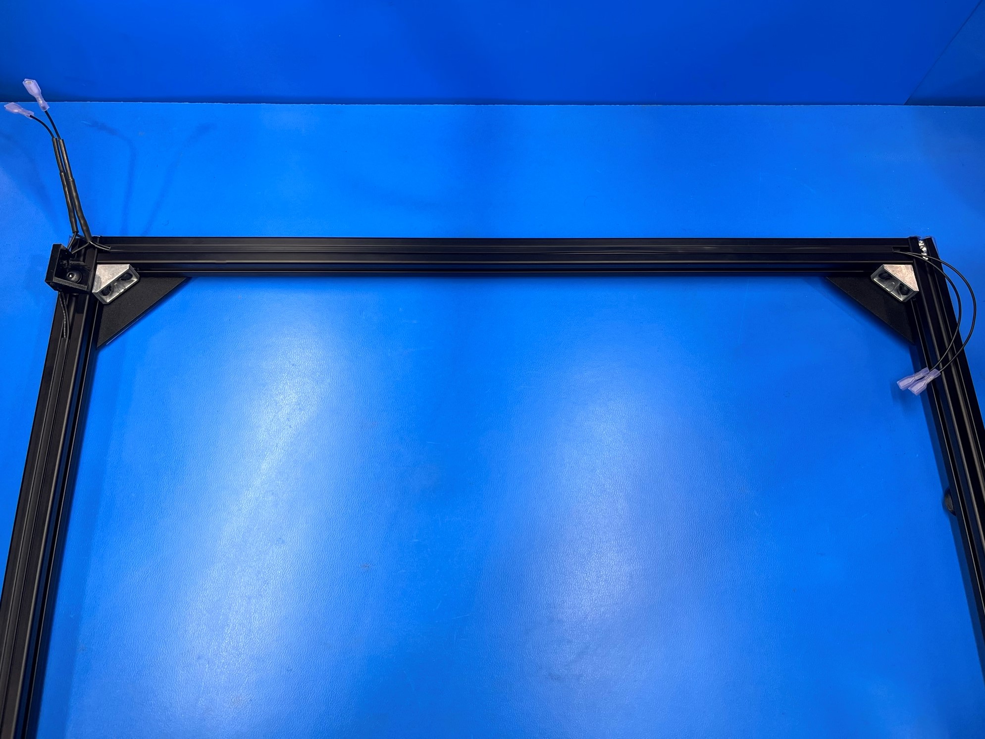
Repeat for the X end left assembly using the top left side of the rear frame.
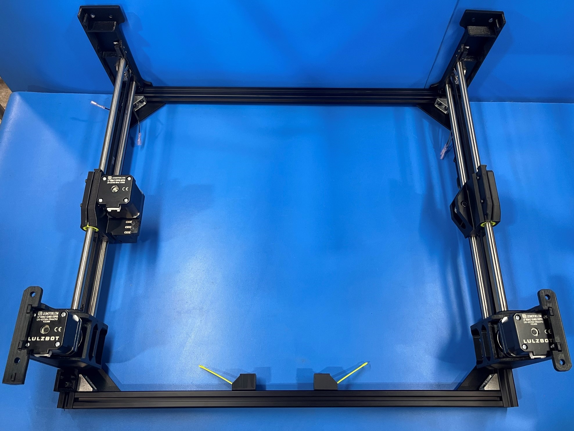
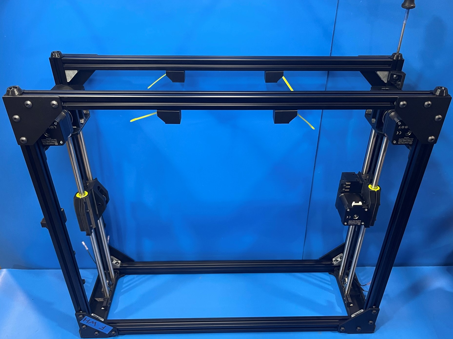
Slide the front frame extrusions into the tabs on the right and left X ends.
Then carefully flip the whole assembly over and use 4x M5x10 HHCS [HD-BT0250] to secure the front frame to the right and left X ends.
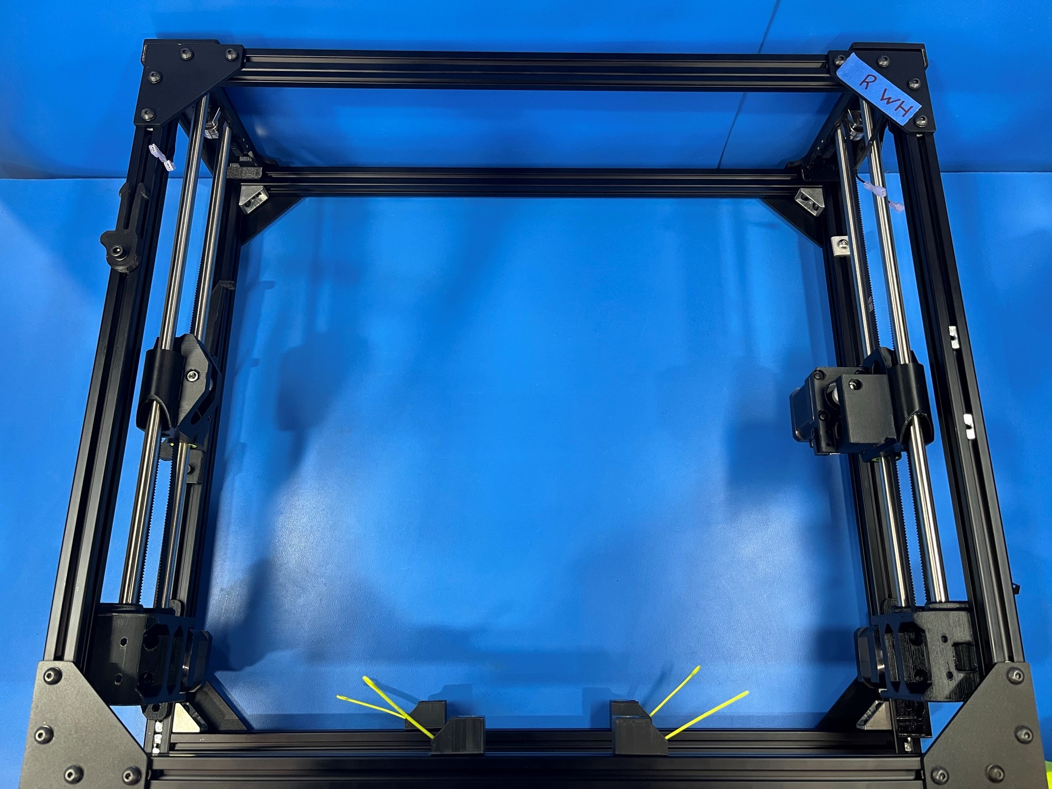
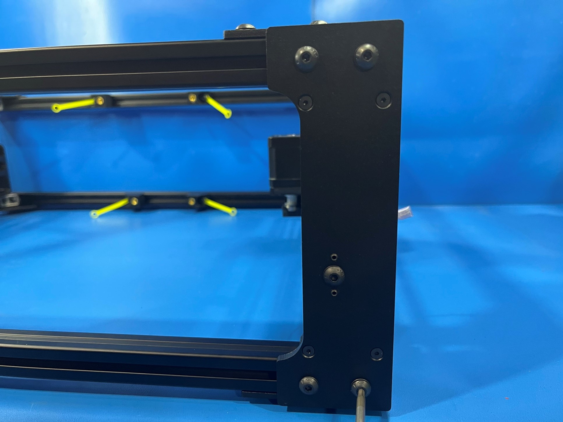
Now turn the assembly so that the top is facing you.
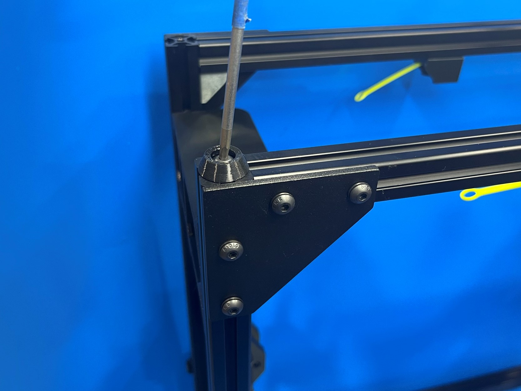
Use 8x M5x10 BHCS [HD-BT0073] with M5 washers [HD-WA0040] to secure right and left X ends to the front and rear frame assemblies.

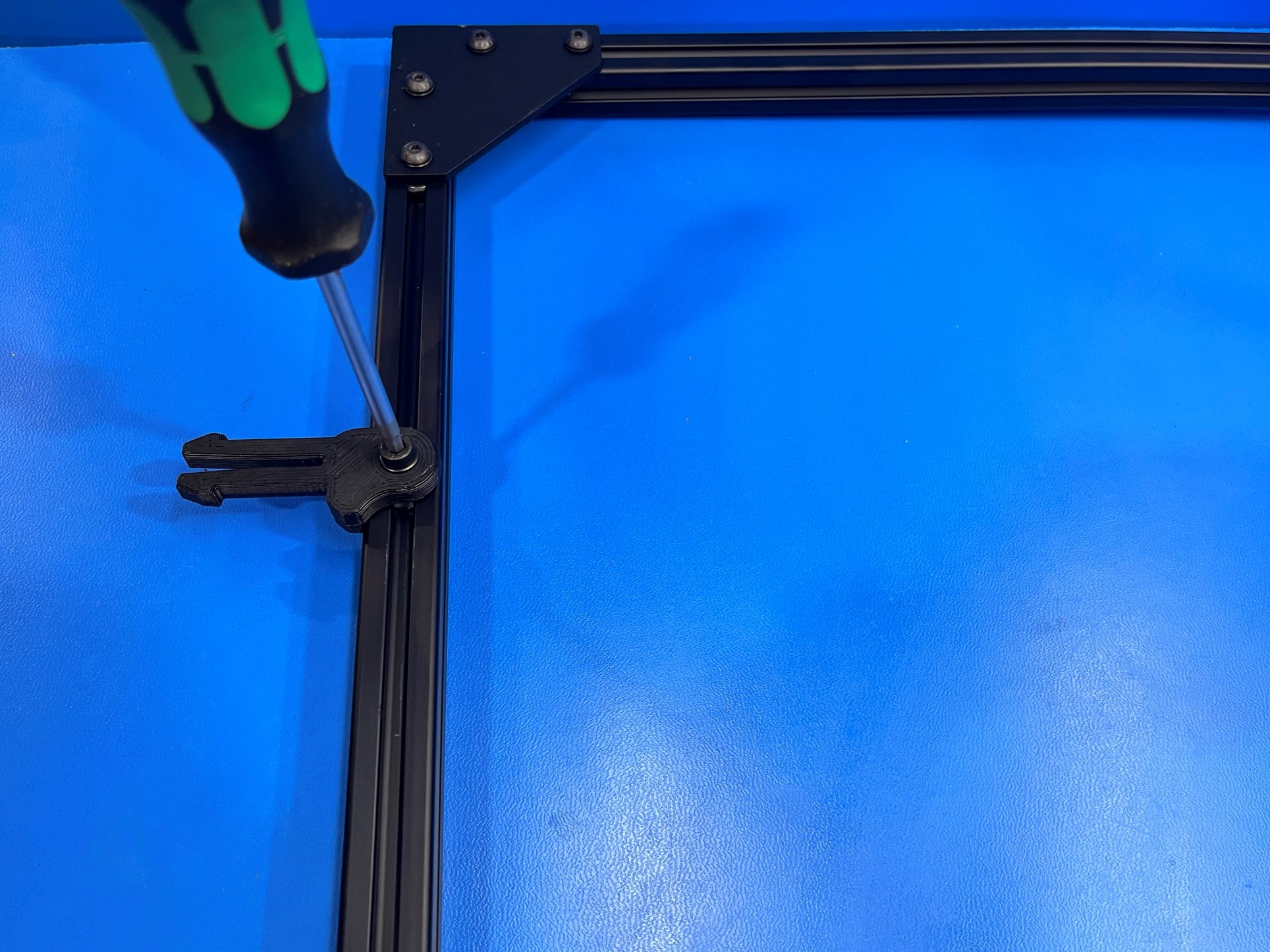
Before using the frame squaring fixture loosen the following bolts:

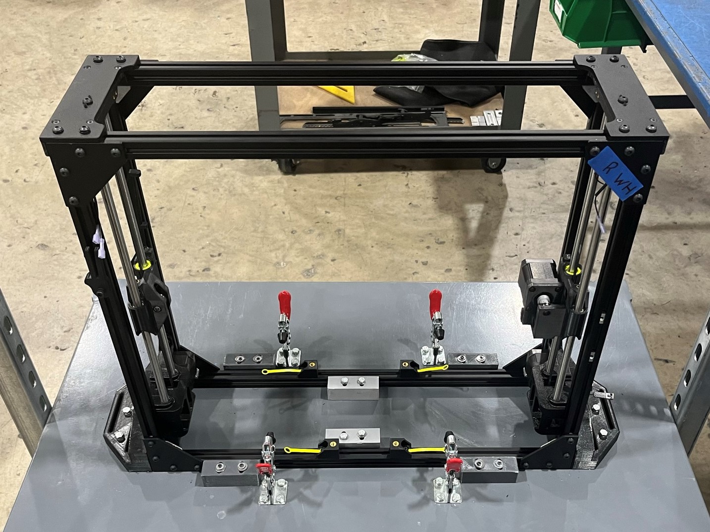
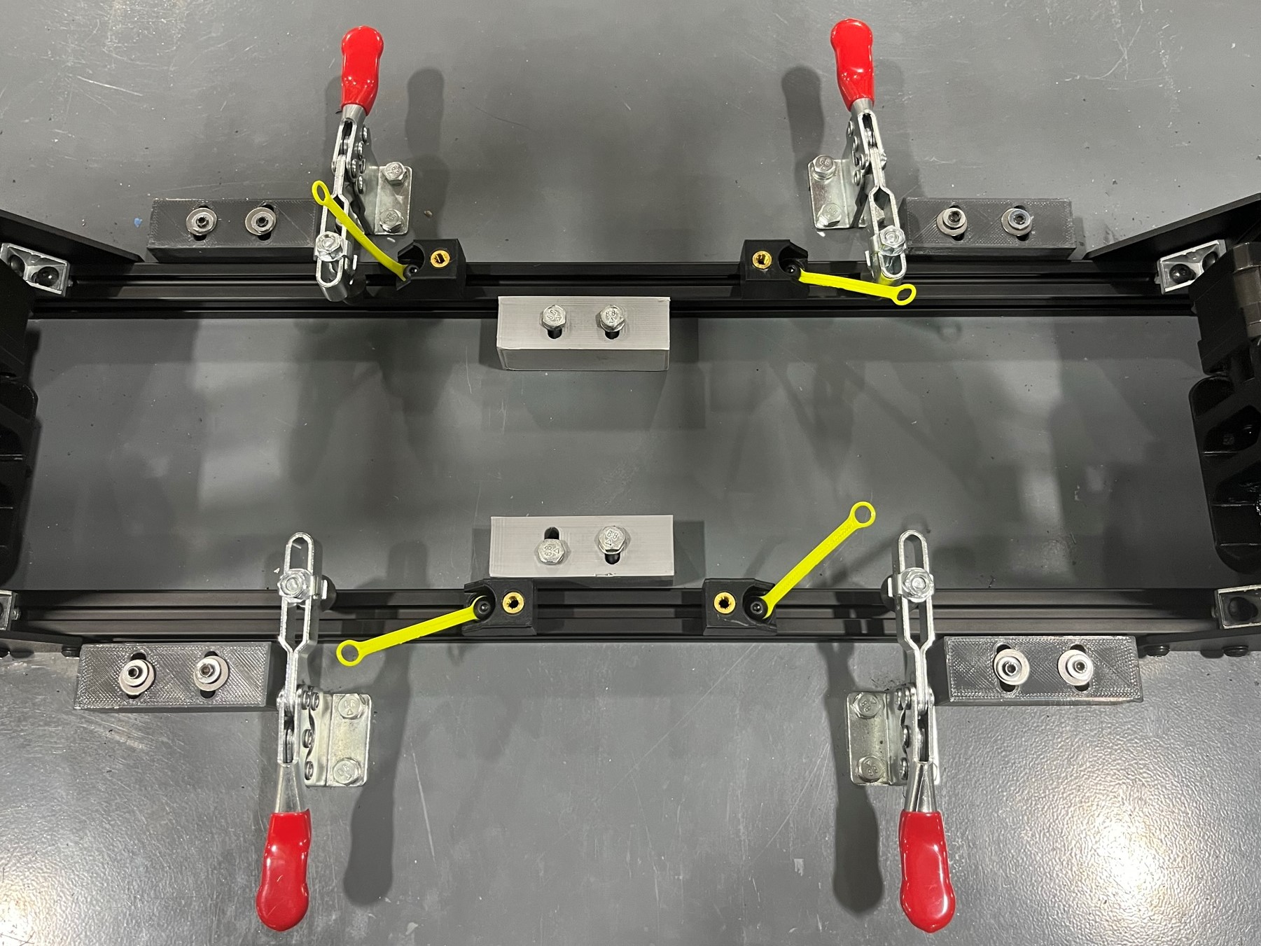
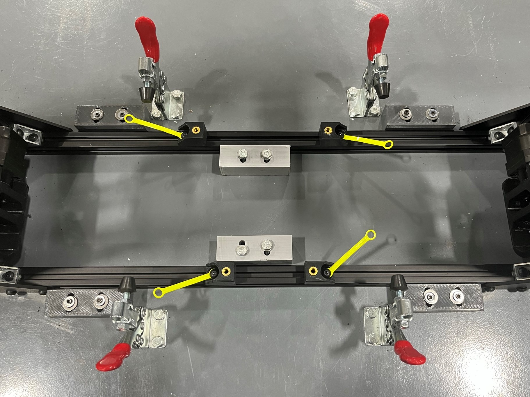
Place the frame inside the frame squaring fixture, then secure the four clamps.
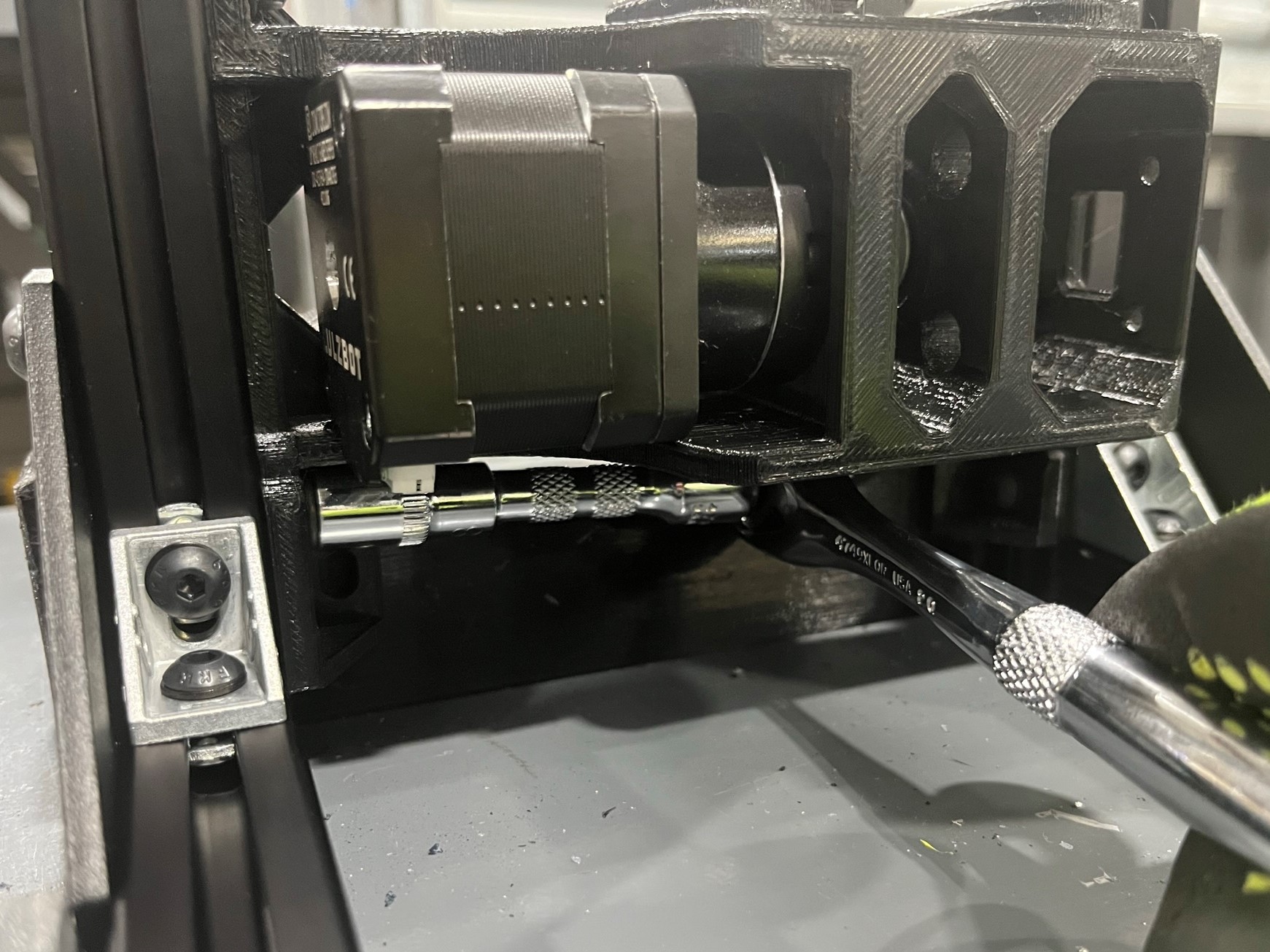
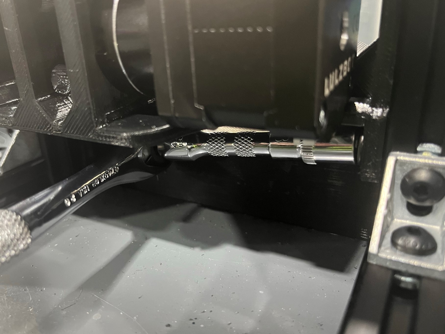
Now use the following tools to tighten the bolts:
Use these tools to tighten the following bolts:
Once the 16 bolts have been tightened, unclamp the frame from the frame squaring fixture.


Install the 4x frame feet [PP-GP0409] to the frame using 4x M5x10 [HD-BT0073] with M5 washers [HD-BT0040].

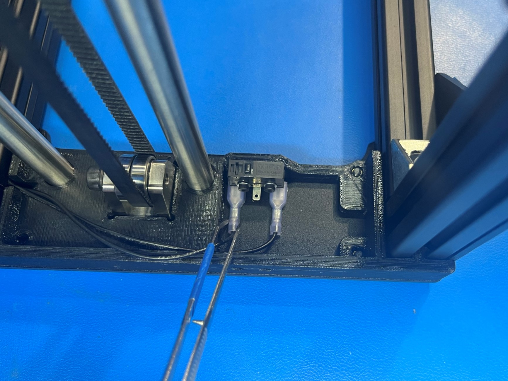
Connect the right and left Z max wires to the limit switches on the top right and left sides of the frame.