Open HardwareAssembly Instructions
Guides for installation and assembly of the LulzBot line of products made by FAME 3D LLC.
Guides for installation and assembly of the LulzBot line of products made by FAME 3D LLC.
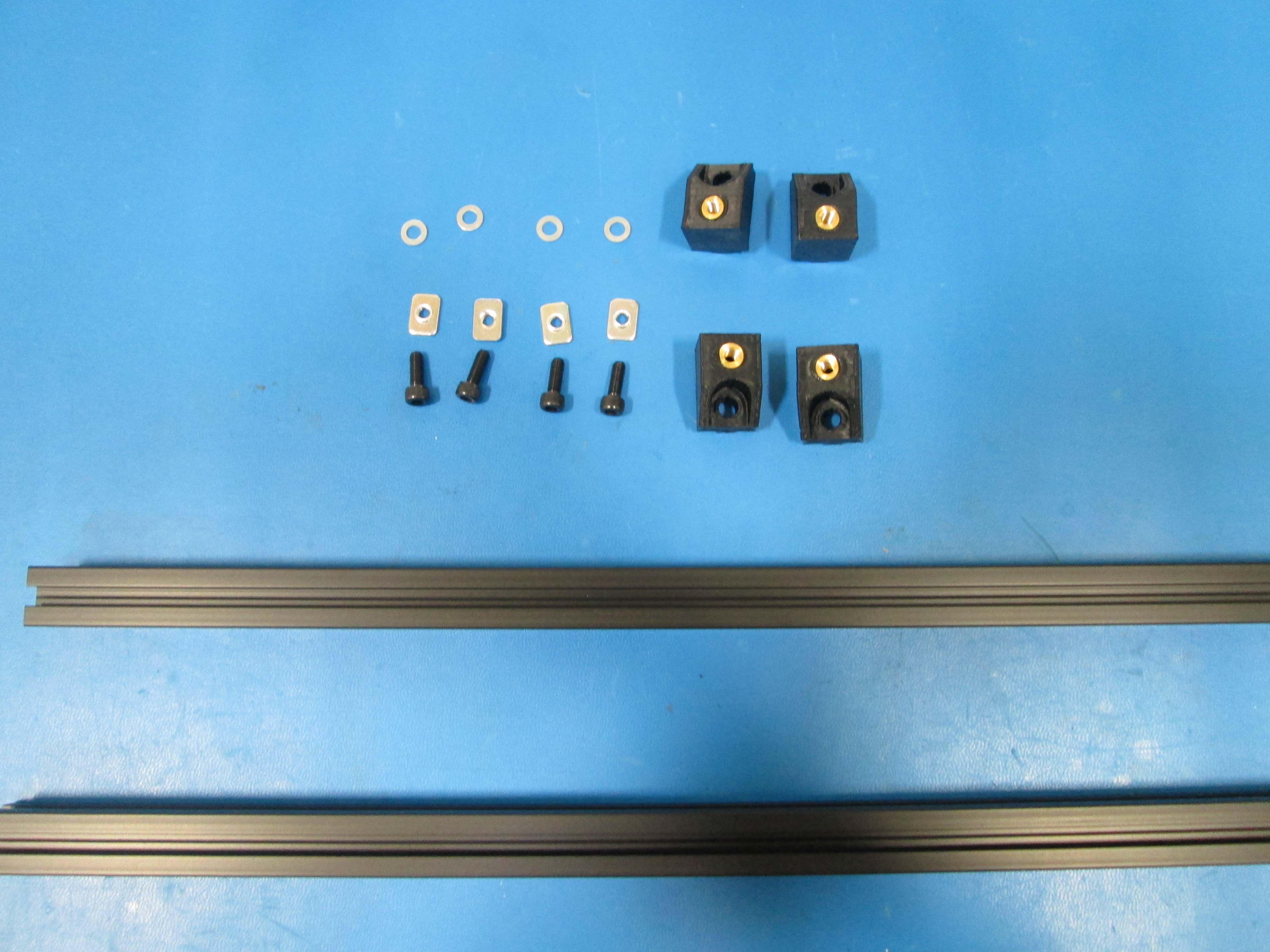
Components
Tools
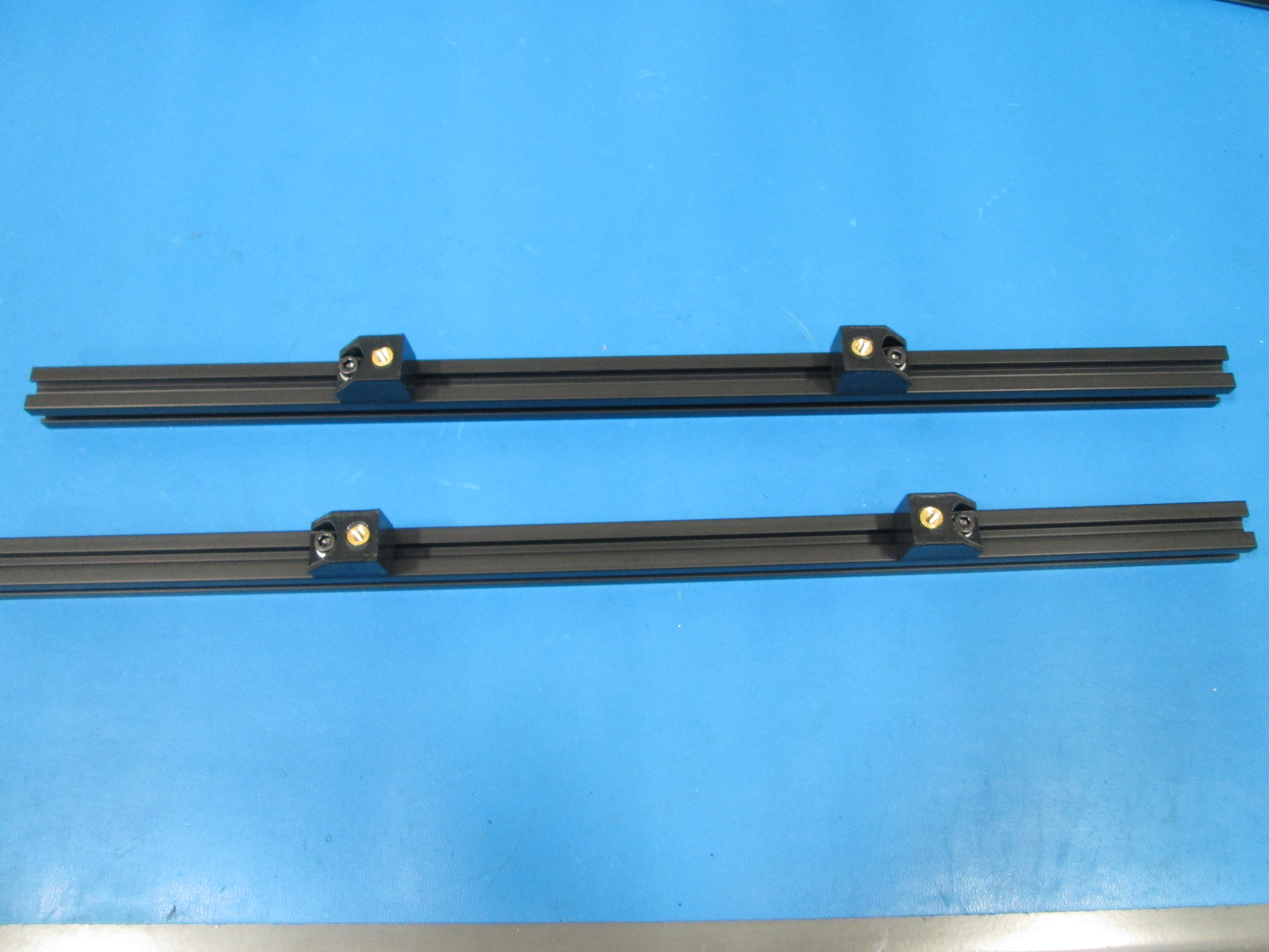
Build 2 of these assemblies.
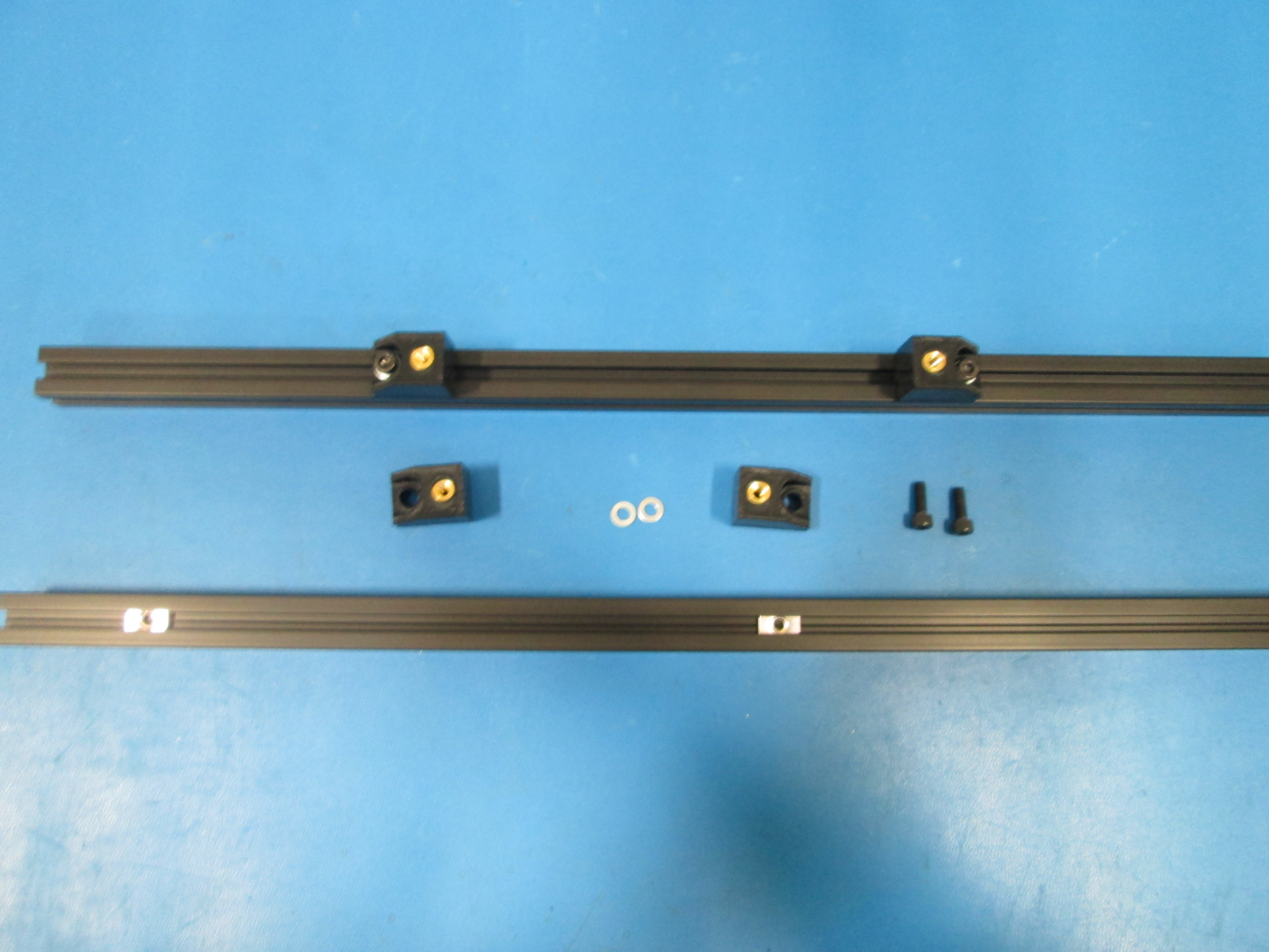
Install two Y mount chassis onto Extrusion with no taps using M5x14 SHCS, M5 Washers and M5 T-nuts.
Take note of the direction of the Y mounts, the side with the threaded insert must face towards the inside.
The location is not important at this point. Snug them down just enough to not slide around during the rest of the assembly.
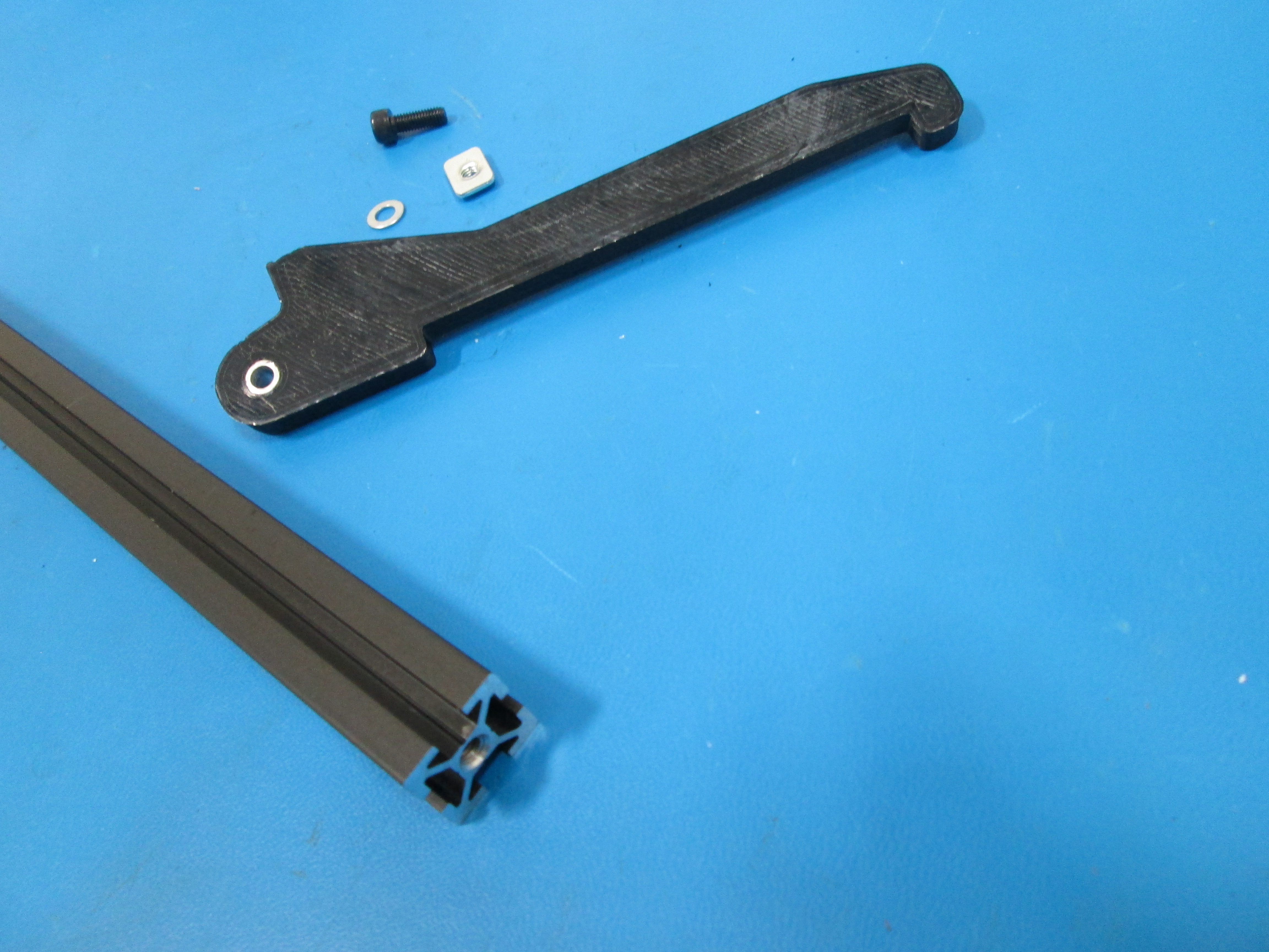
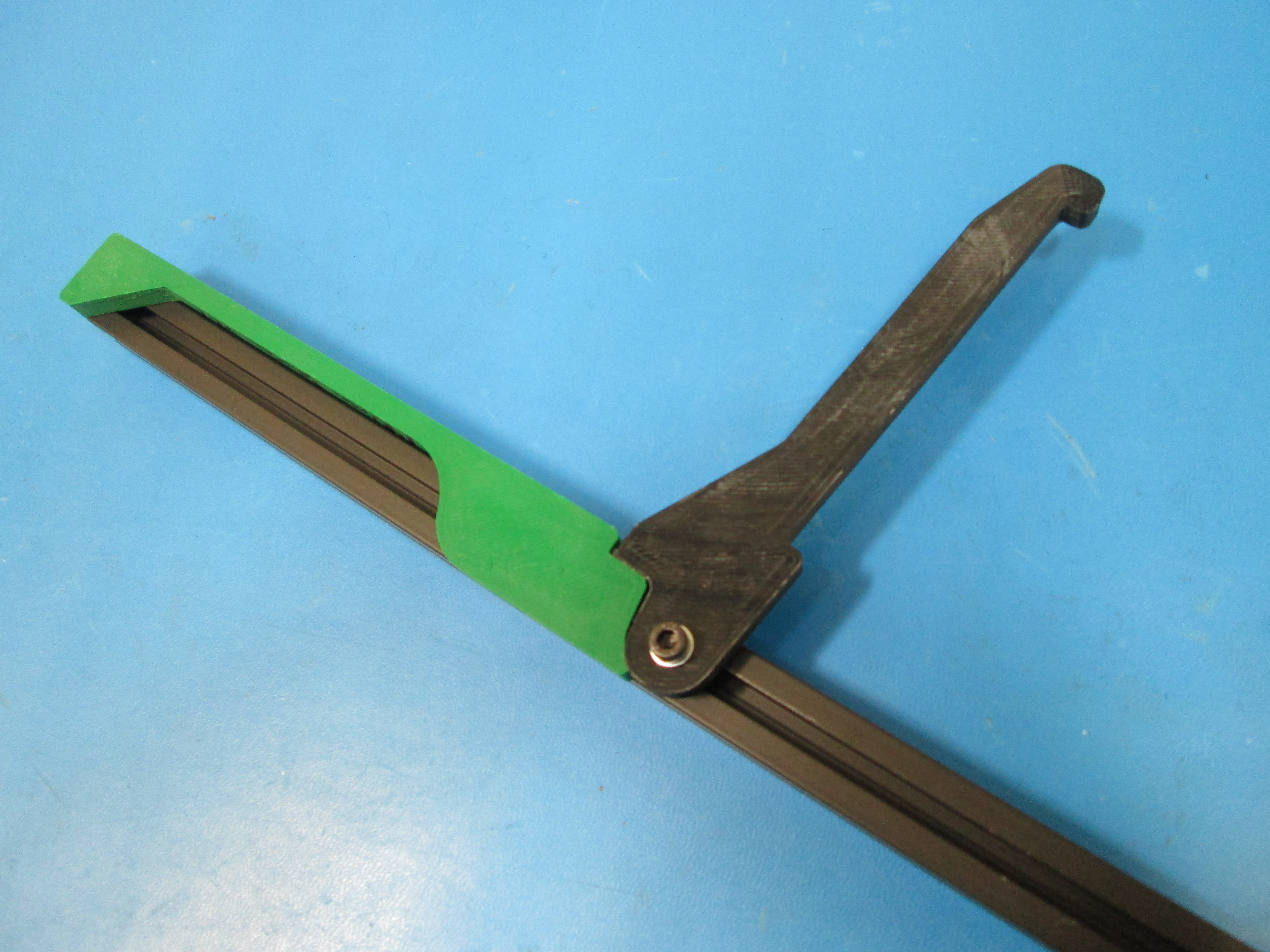
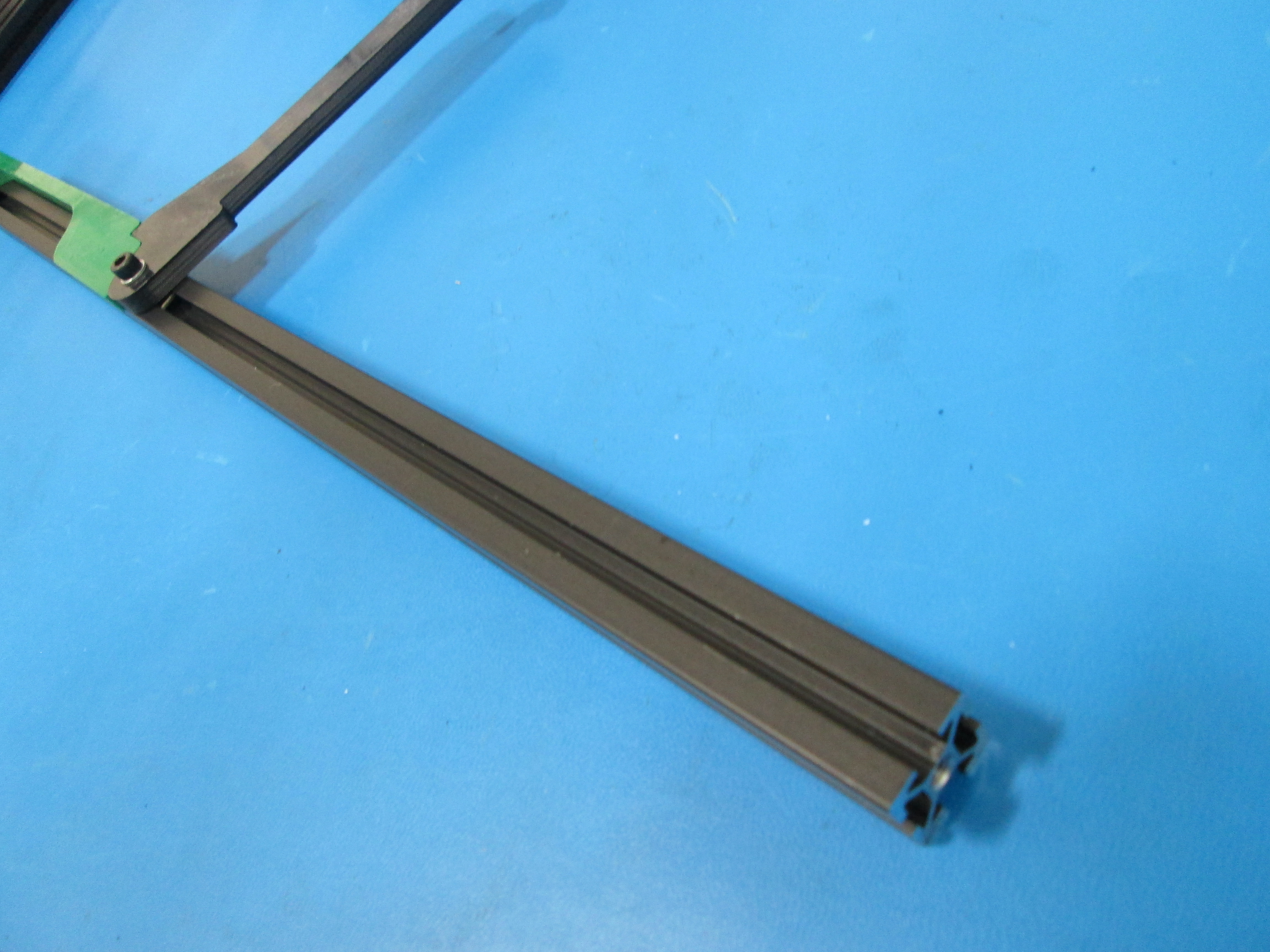
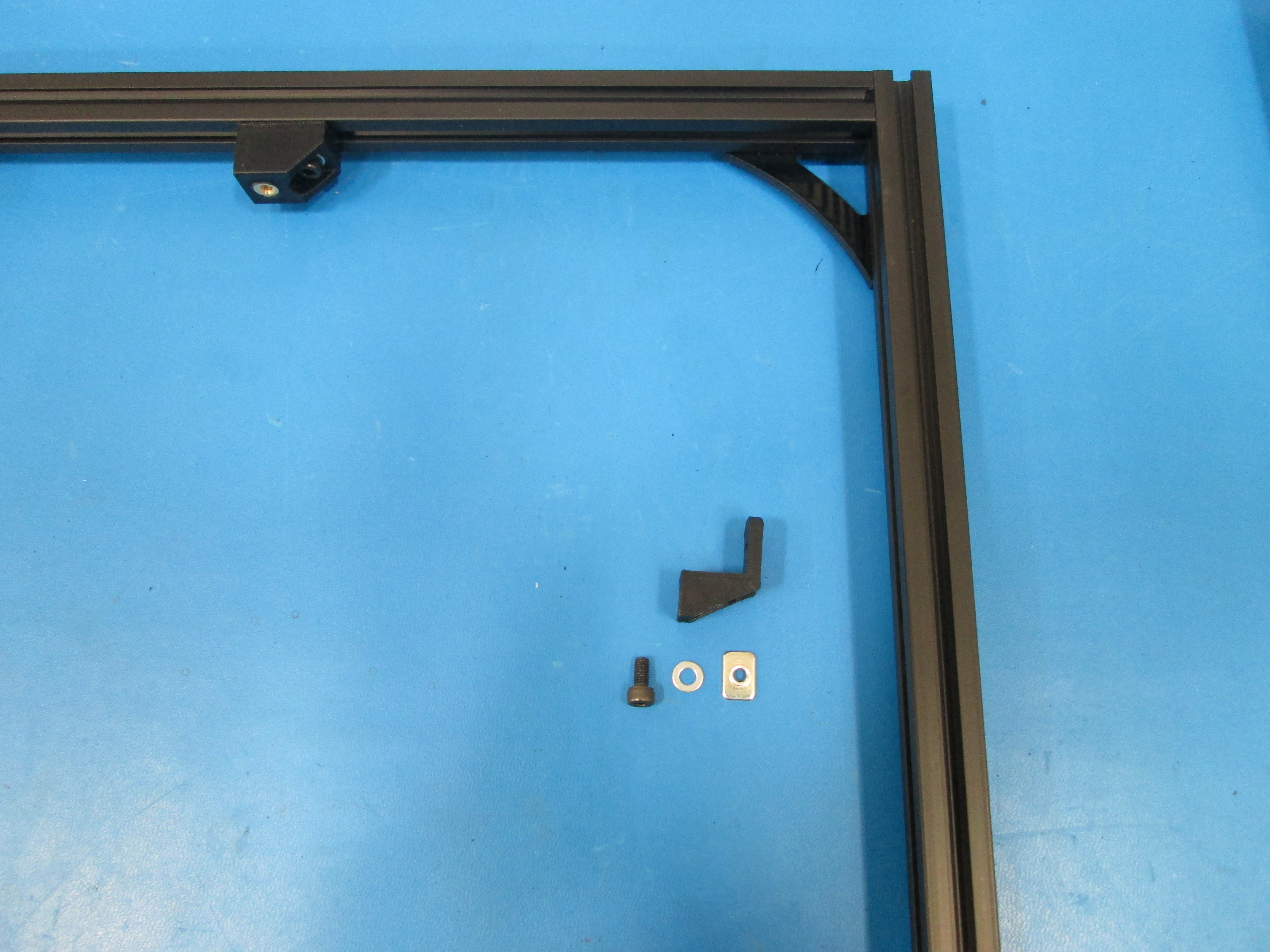
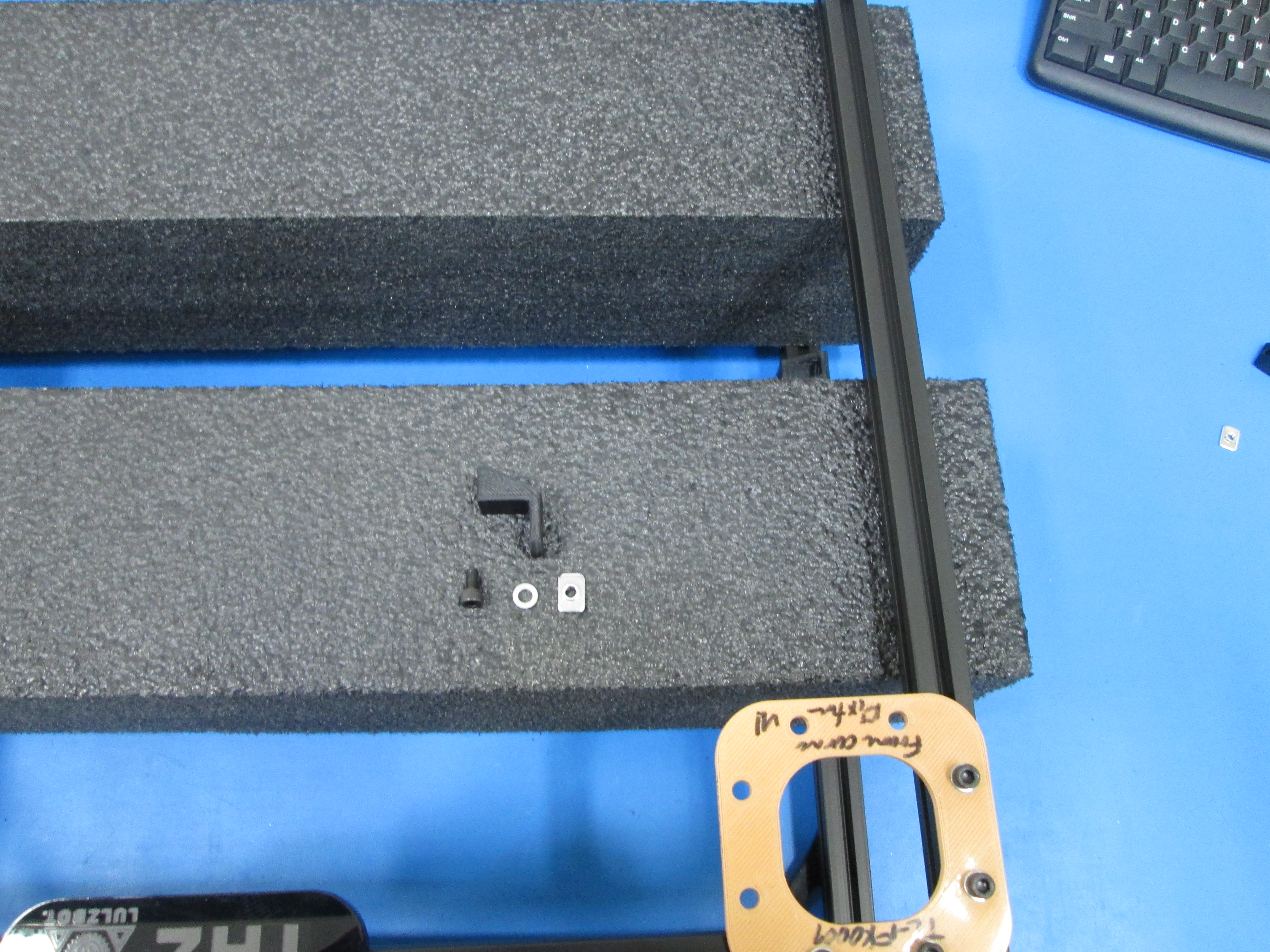
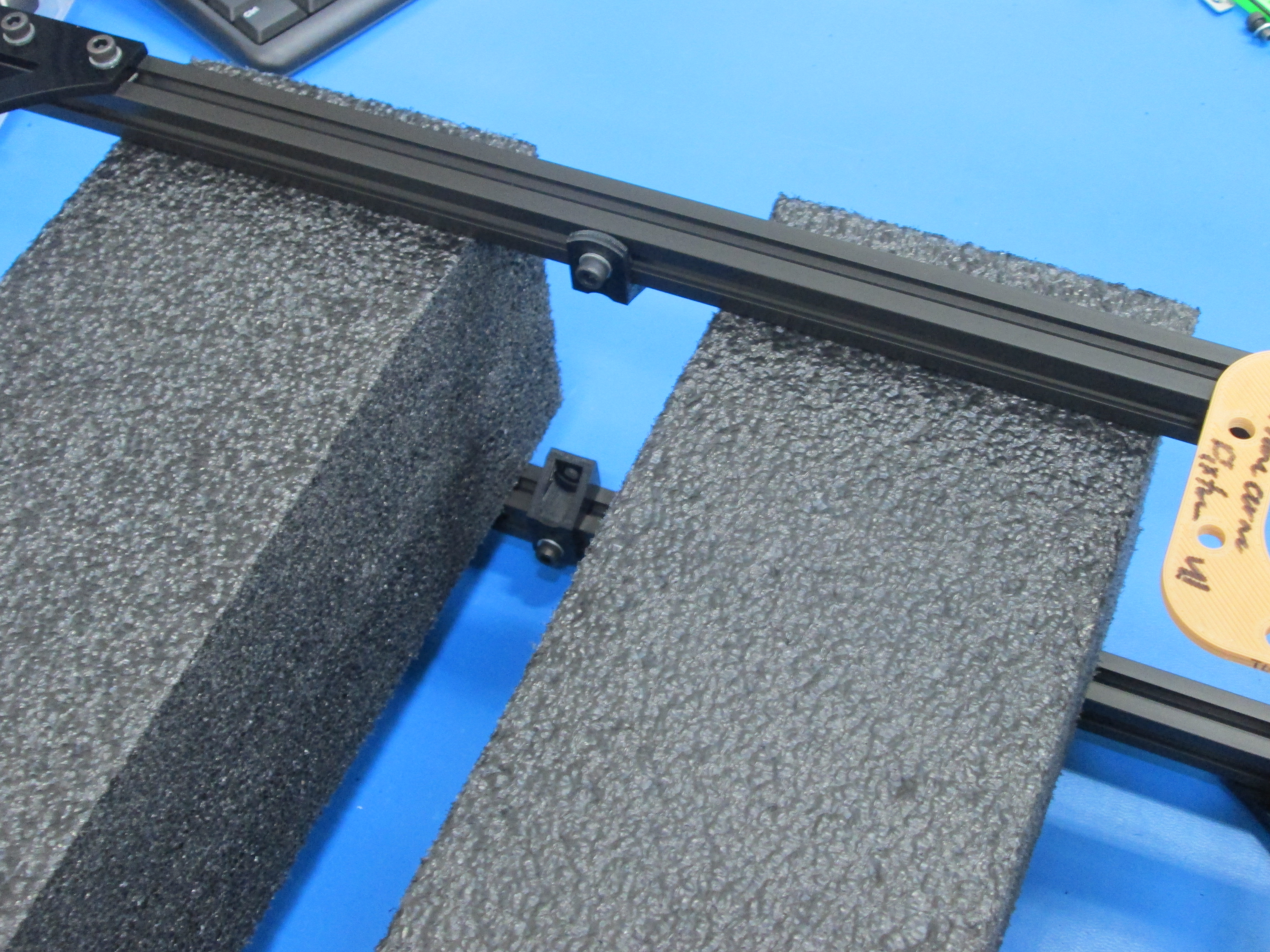
Use 1x M5x14 SHCS and M5 Washer to bolt on the Spool Arm. Take note of the tapped end of the extrusion.
Set the location of the arm using the TL-FX0011 fixture, or 190 mm from bottom of extrusion to spool arm.
Slide 2x M5 T-nuts into the slot on the bottom right extrusion.
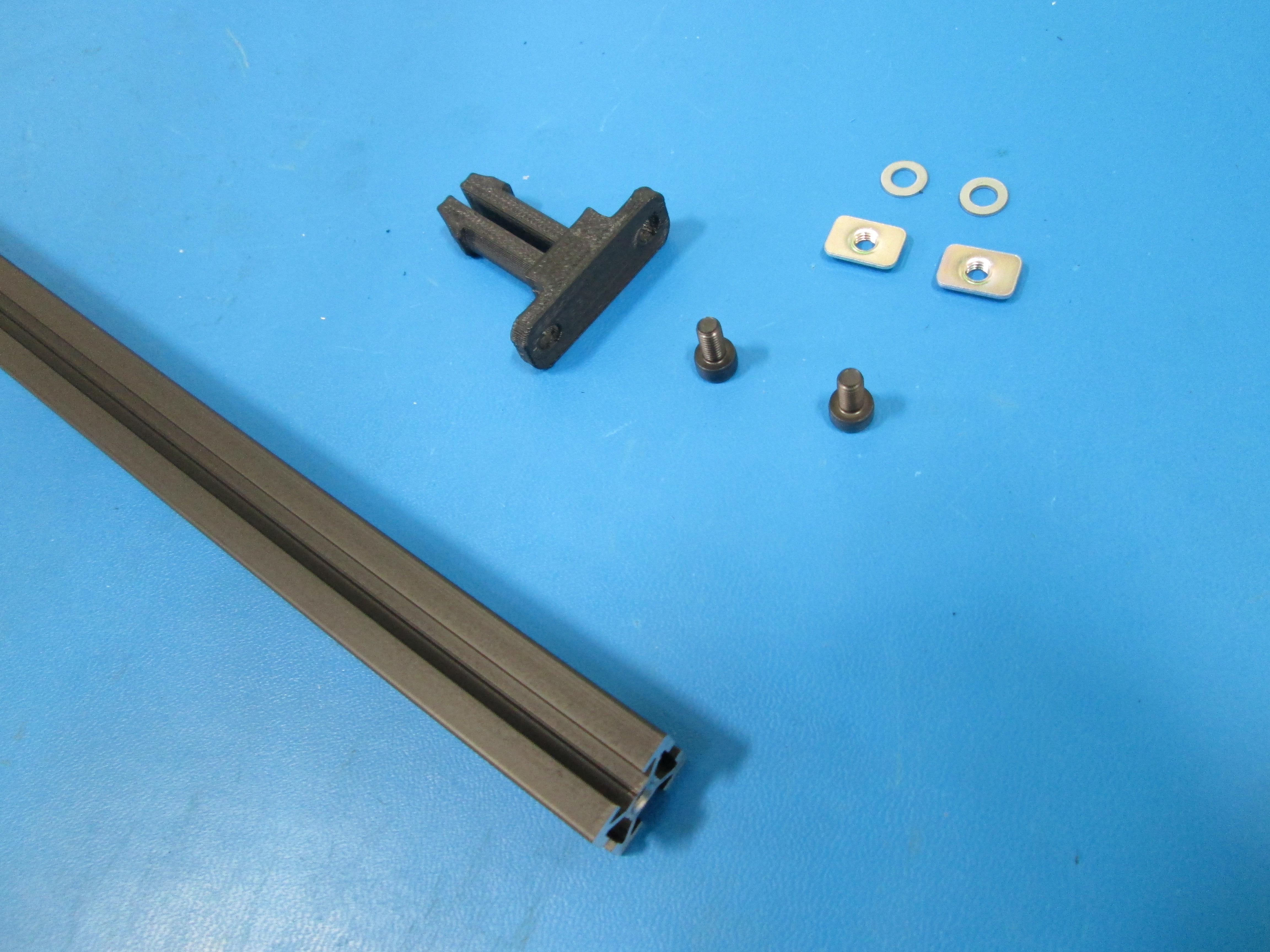
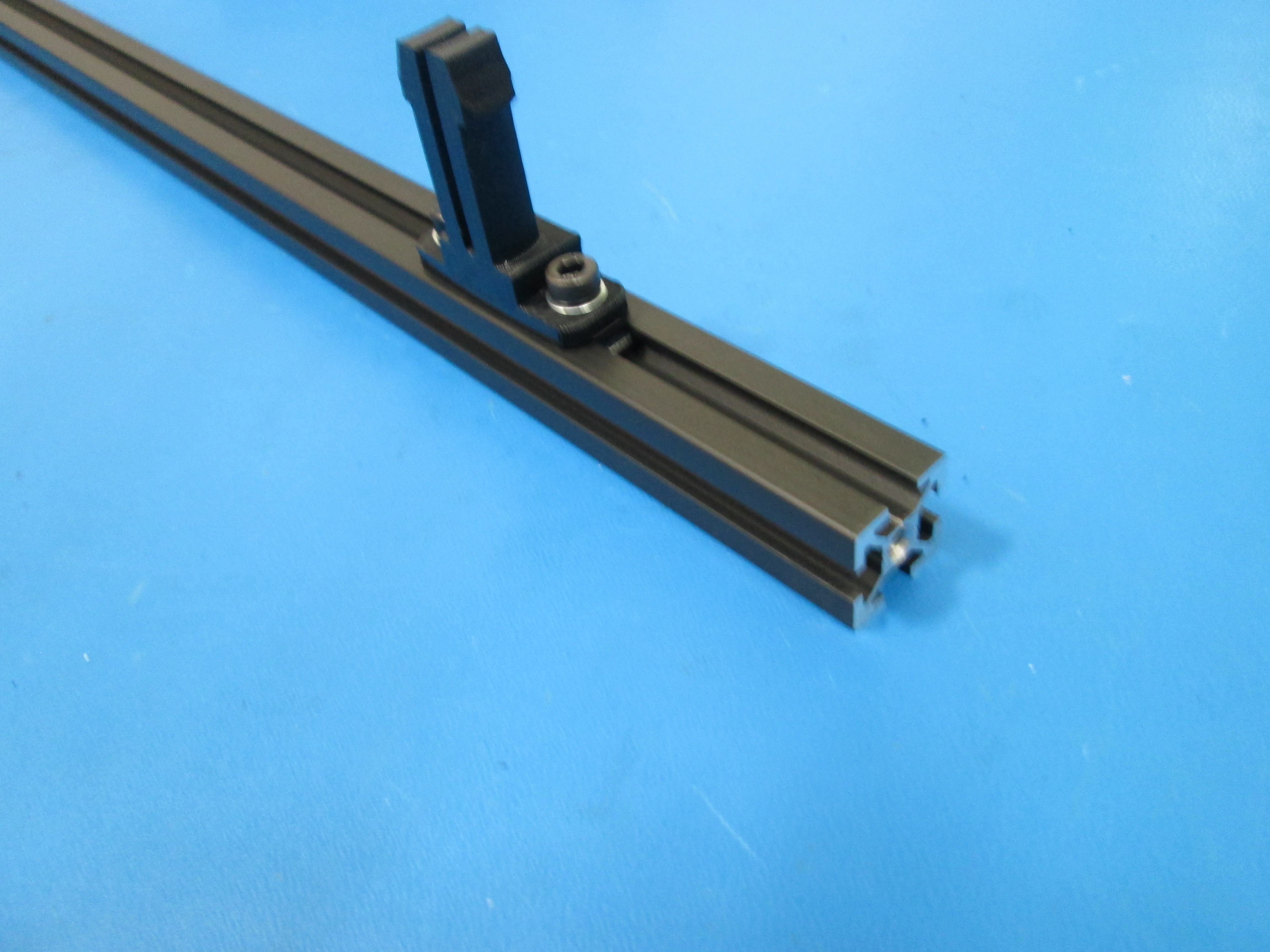
Install the Feet tube holder approximately 20 mm from tapped end of extrusion with 2x M5x10mm SHCS and M5 washers, make sure feed tube holder is slid to the top at the end of assembly.
Take note of tapped end of extrusion and orientation of feed tube holder.
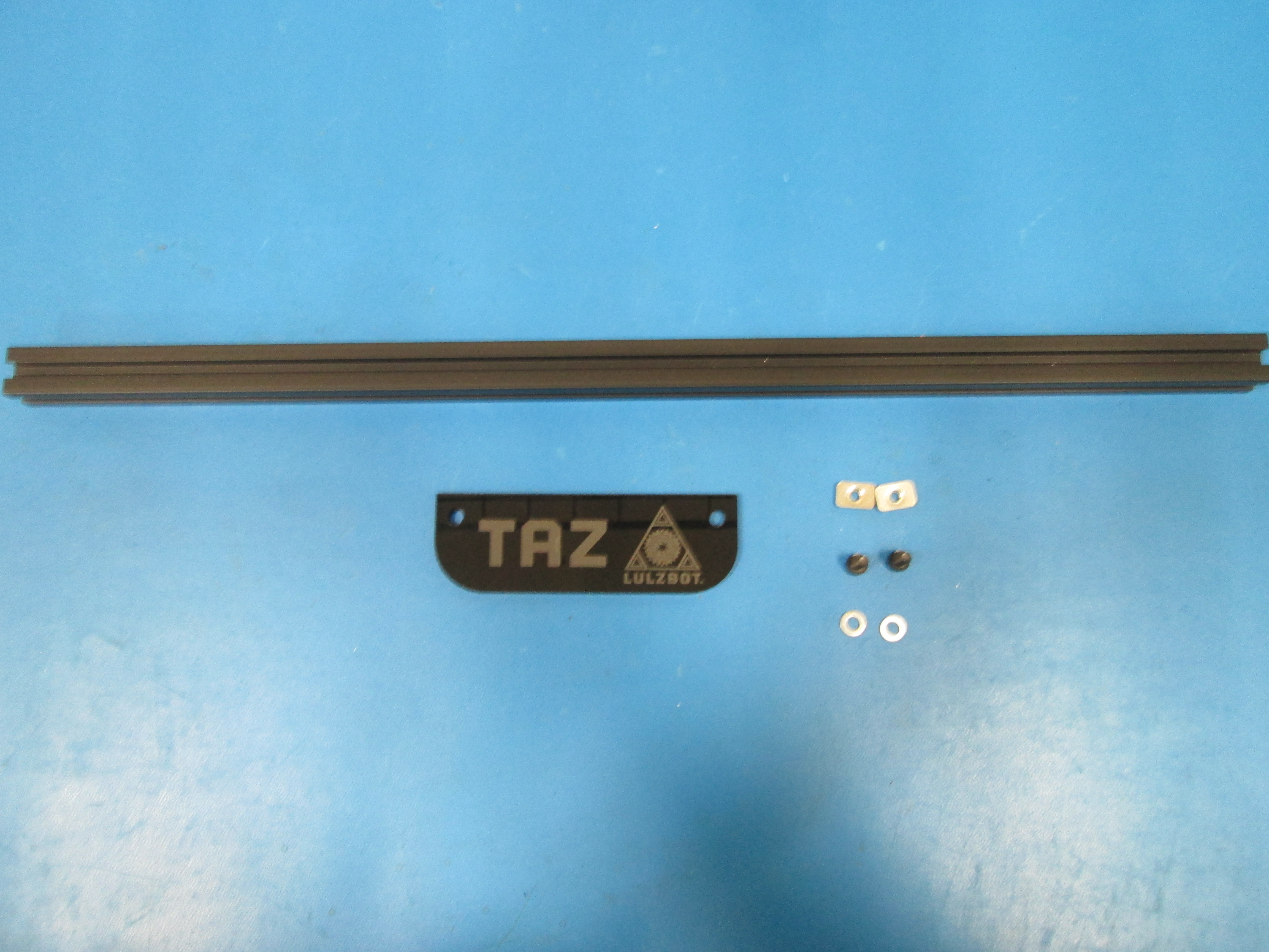
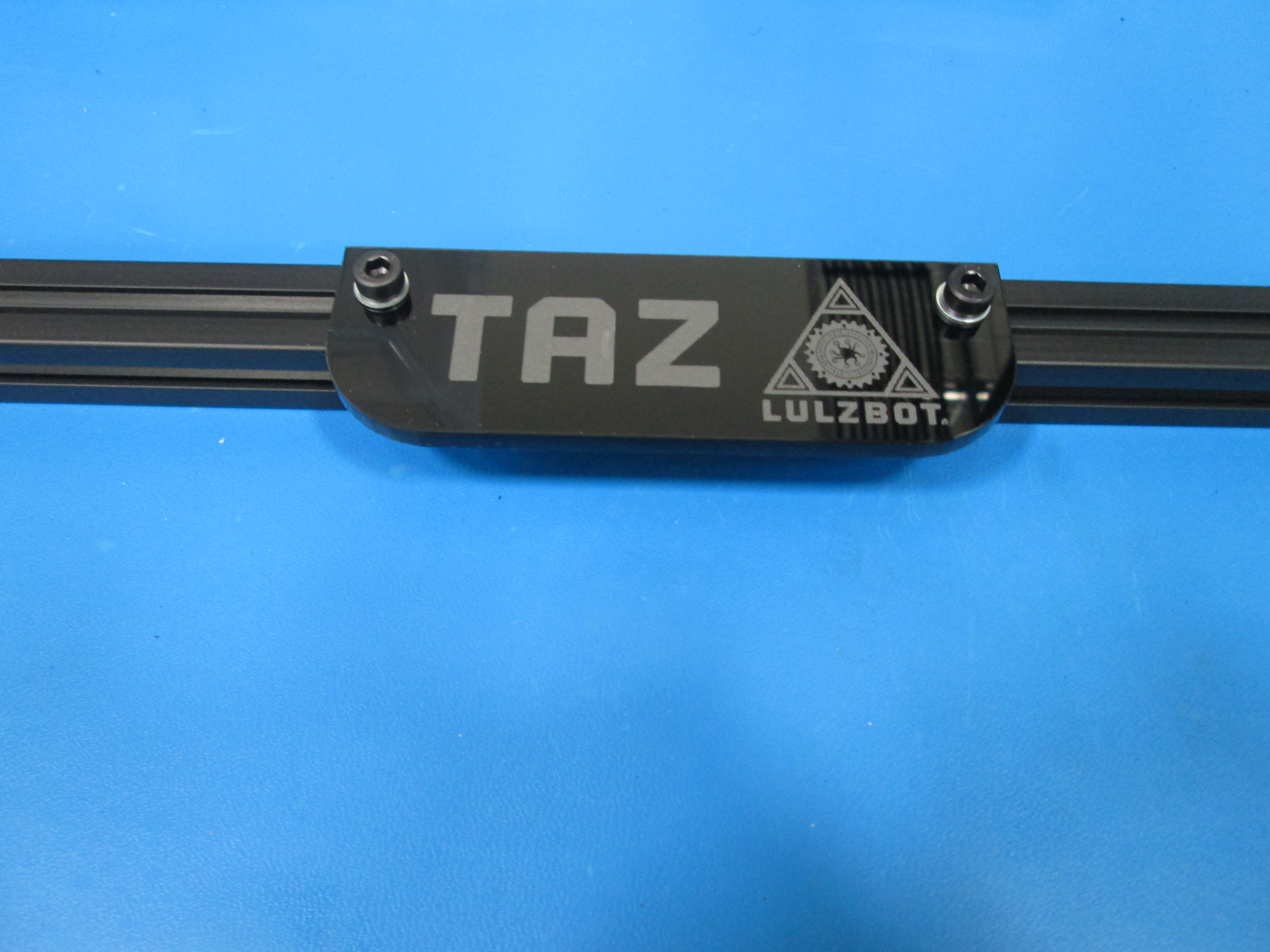
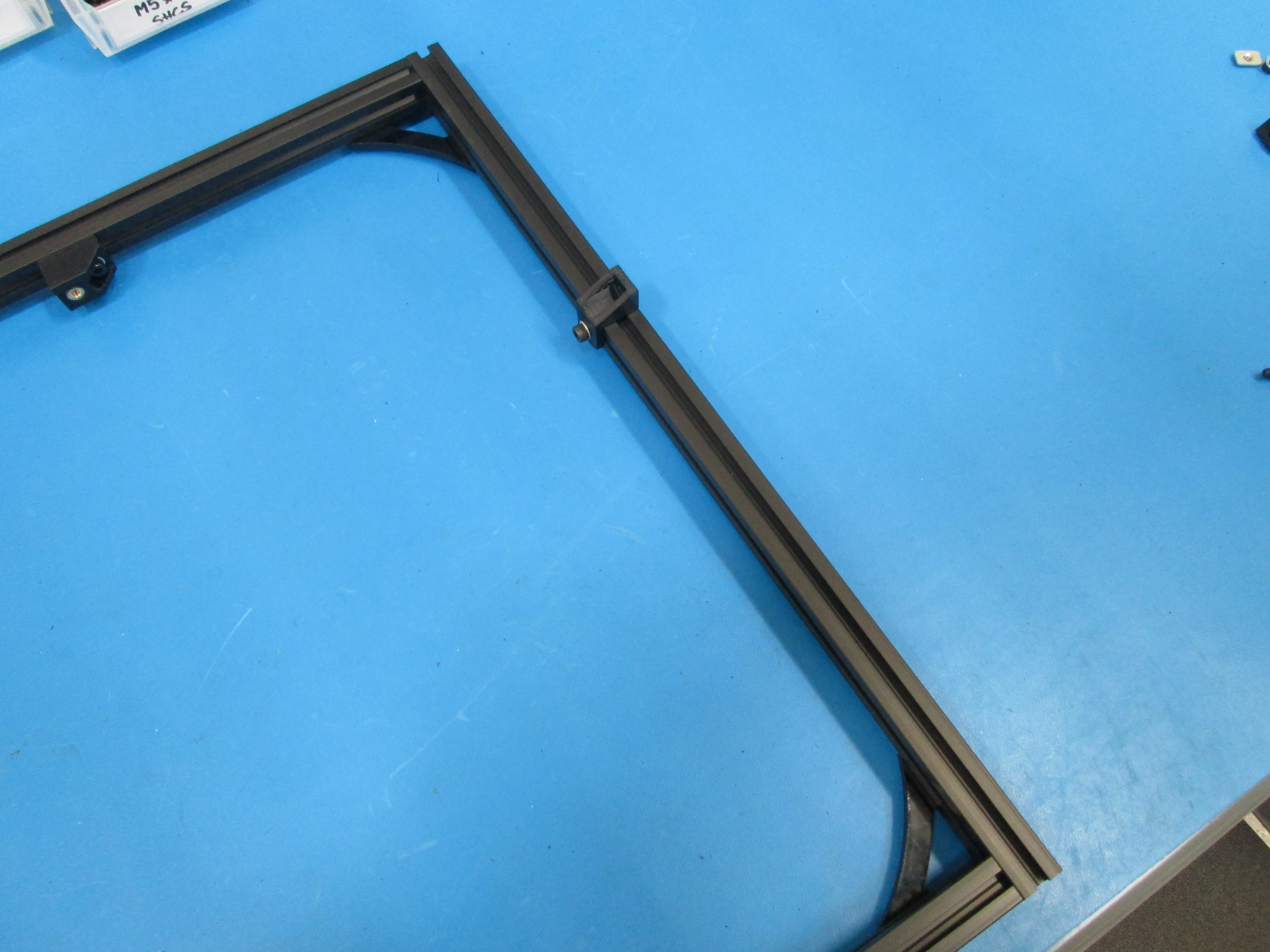
Using the 2x M5 T-nuts in an extrusion that is not tapped, install the name plate with 2x M5x10 SHCS and M5 Washers.
Just center it for now.
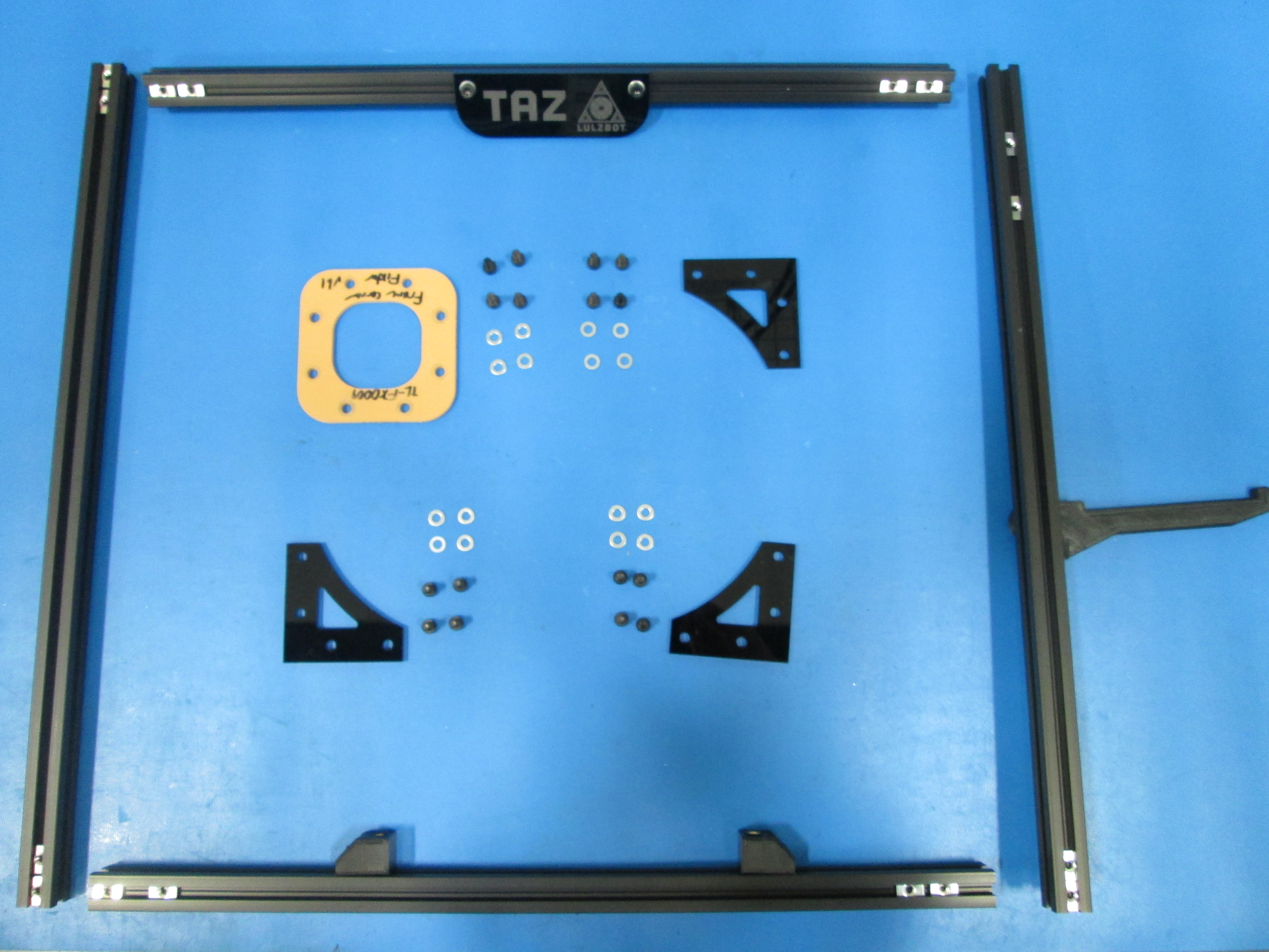
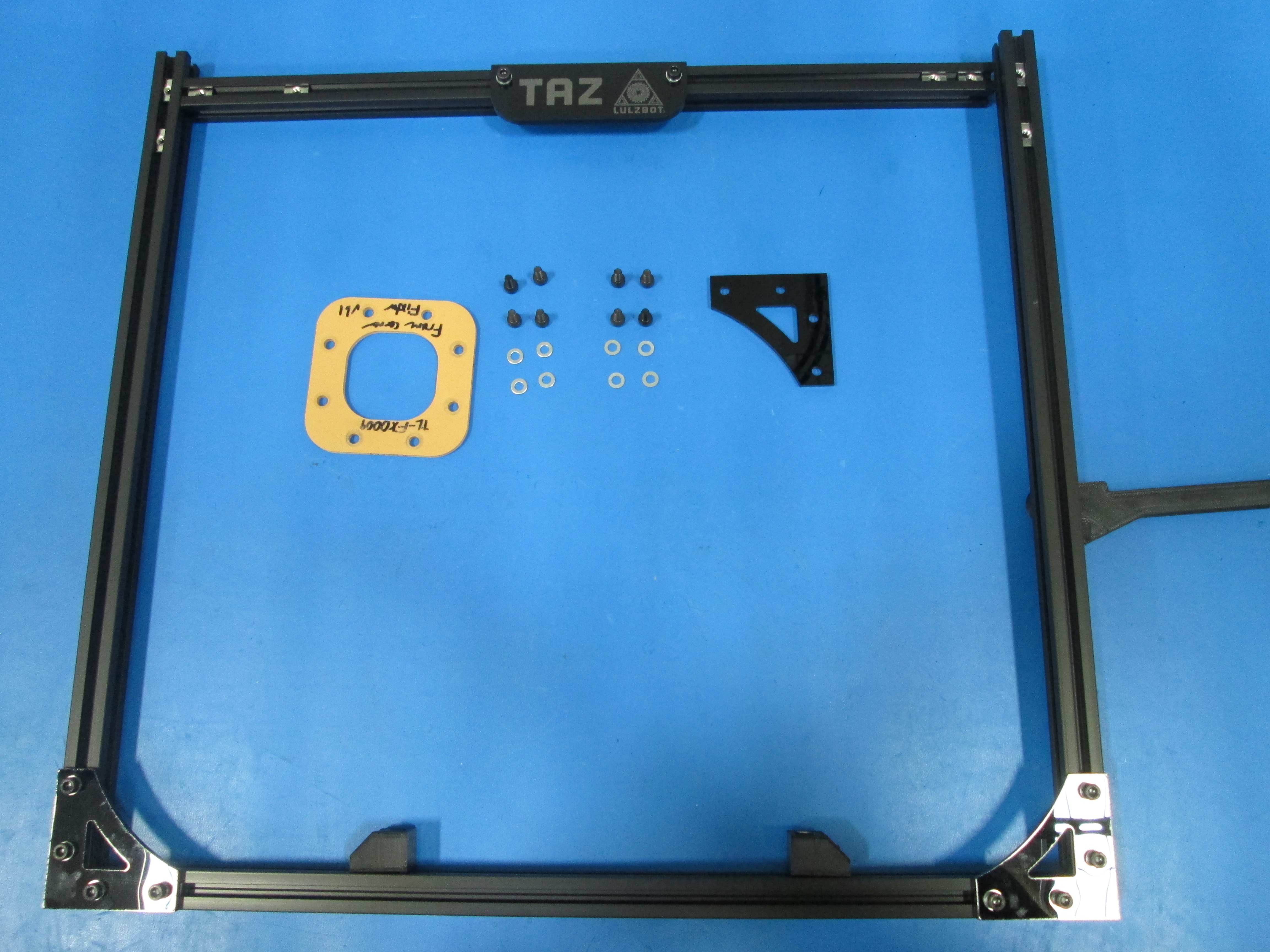
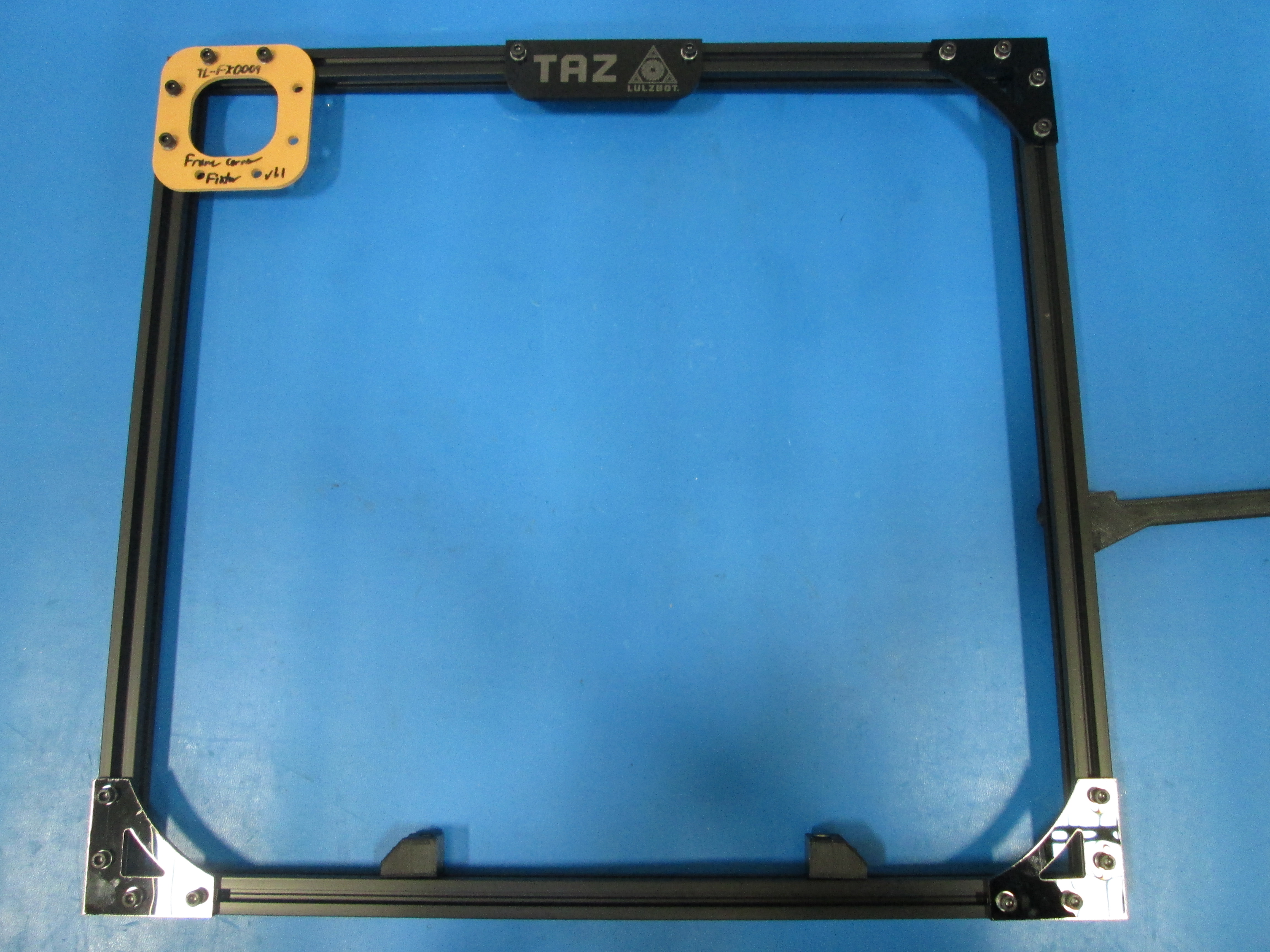
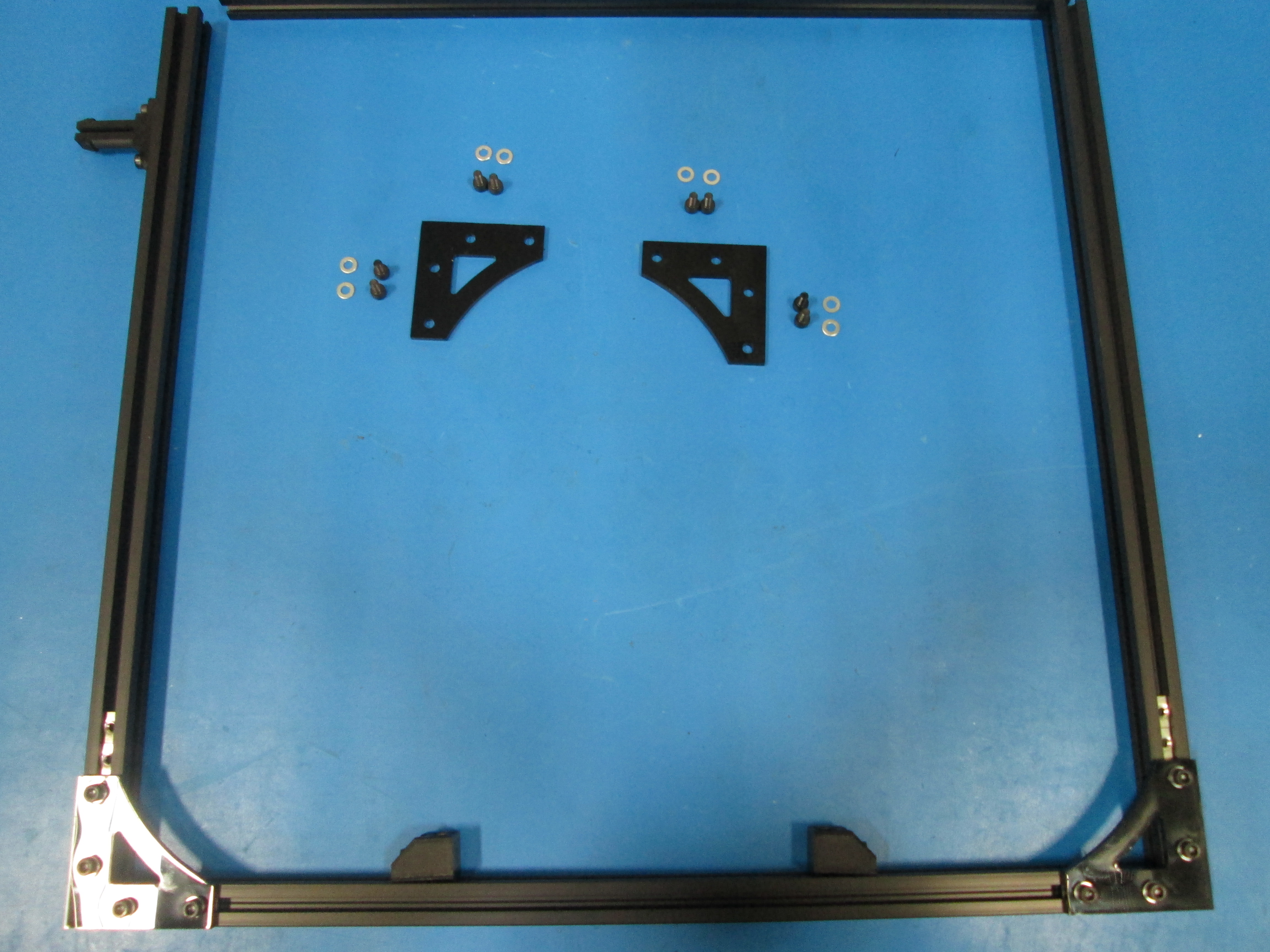
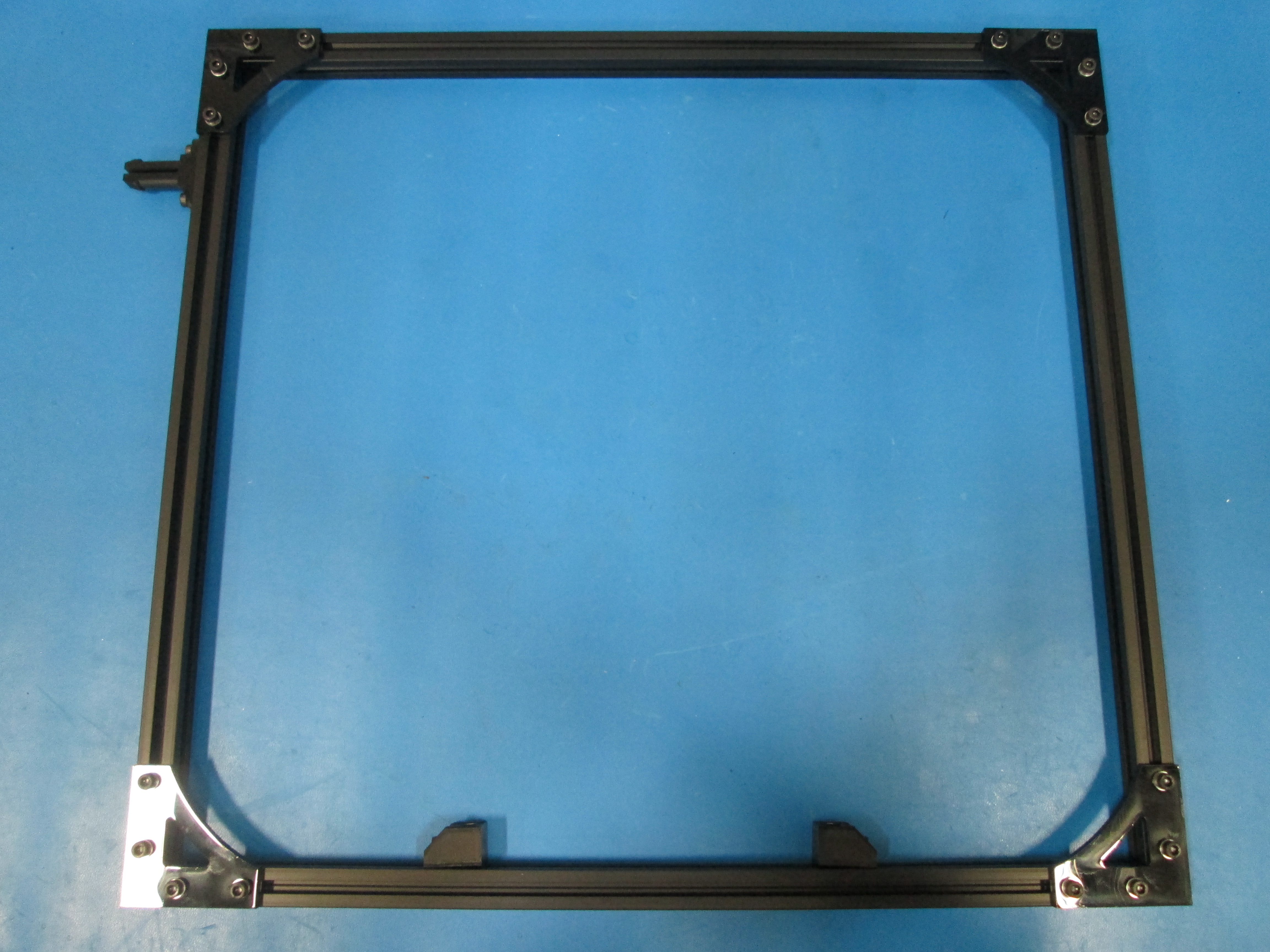
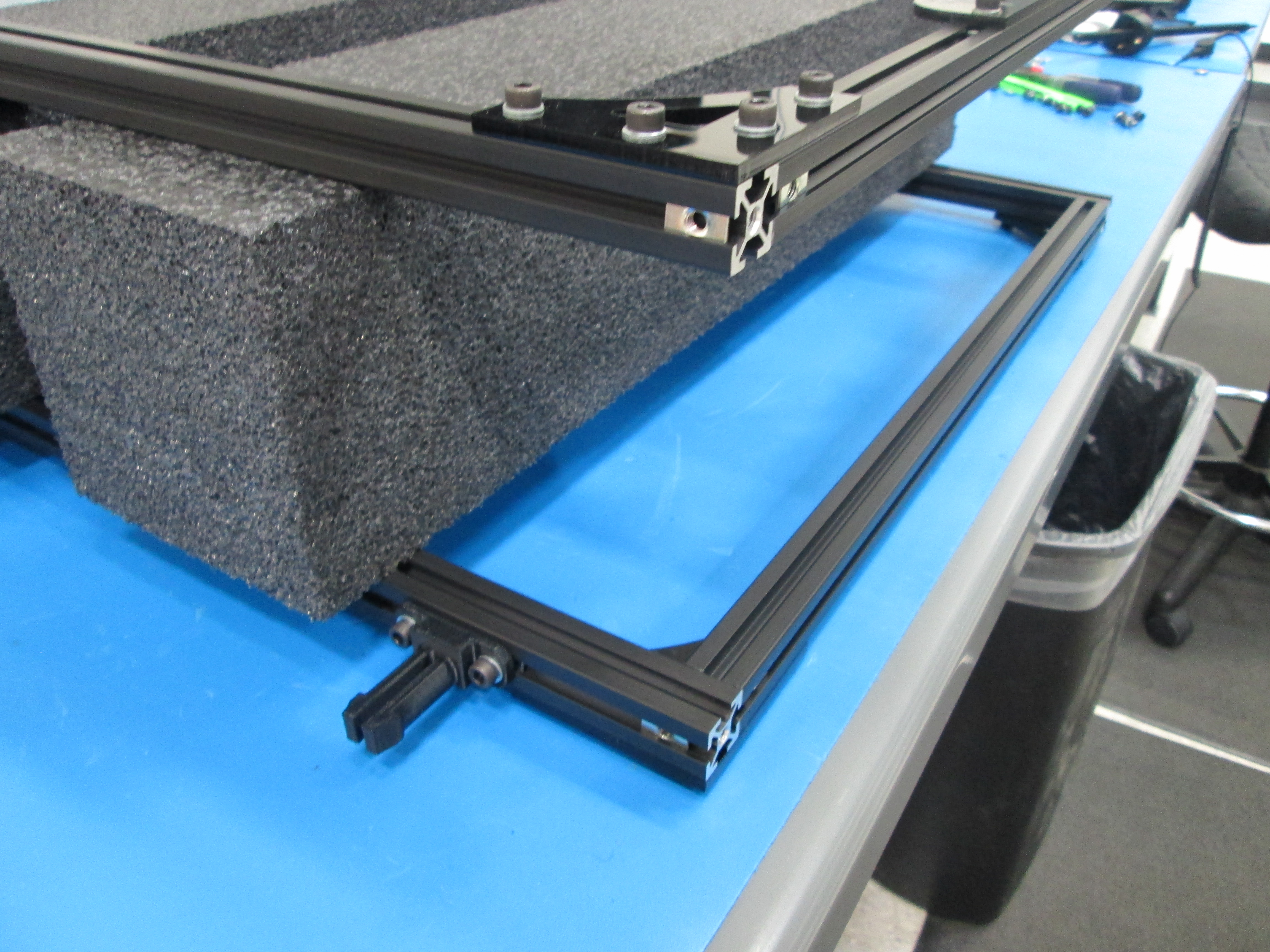
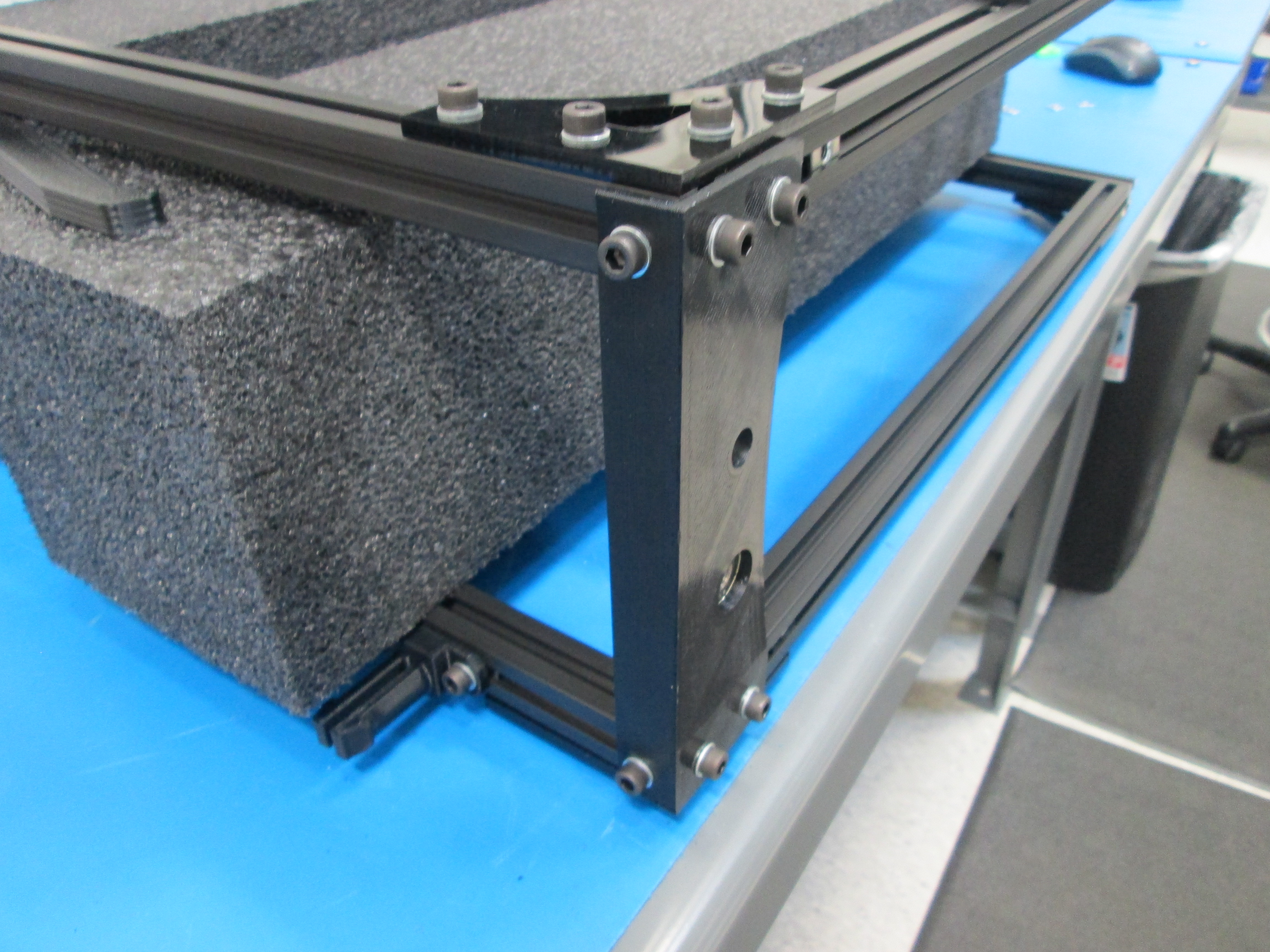
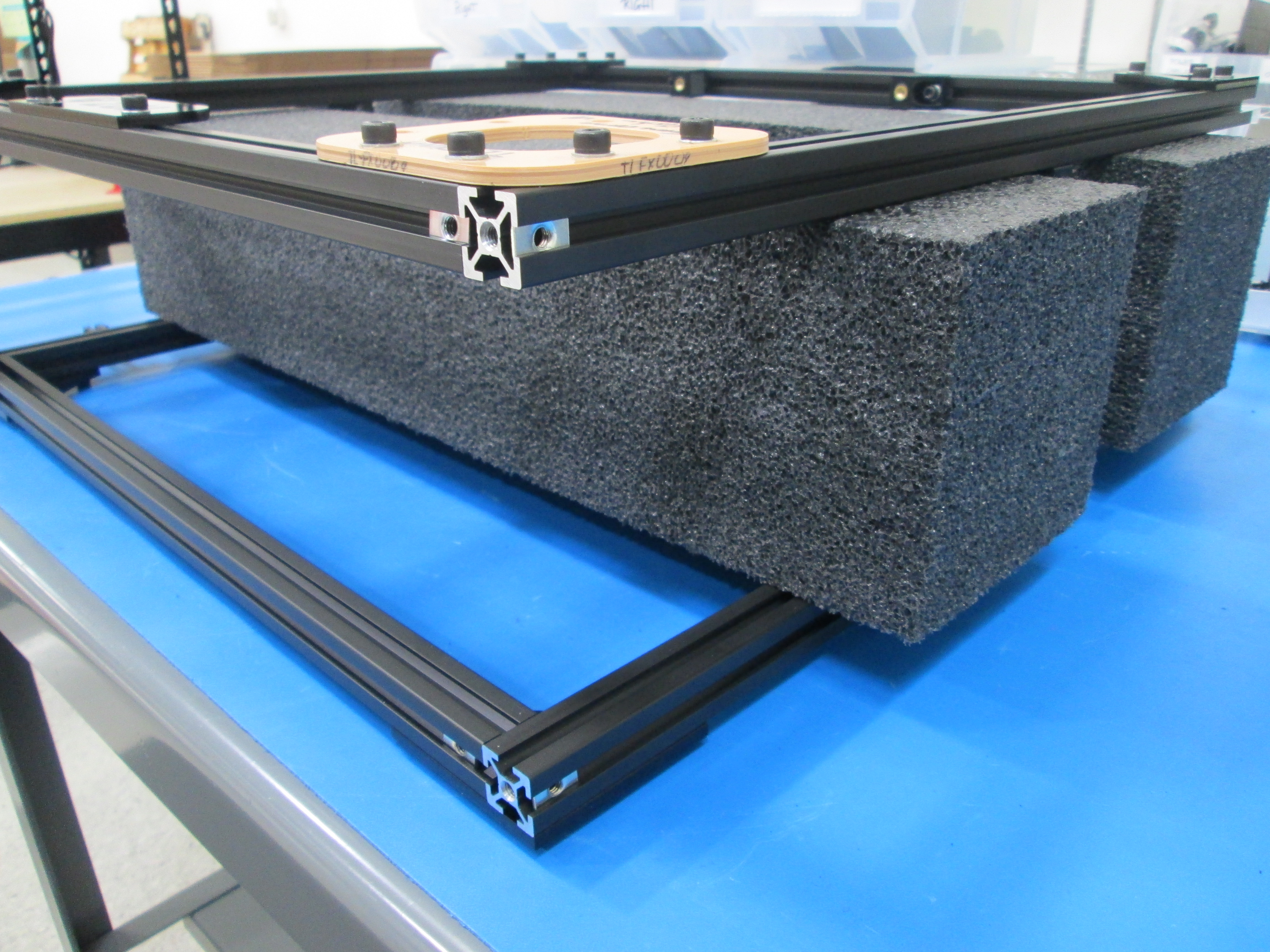
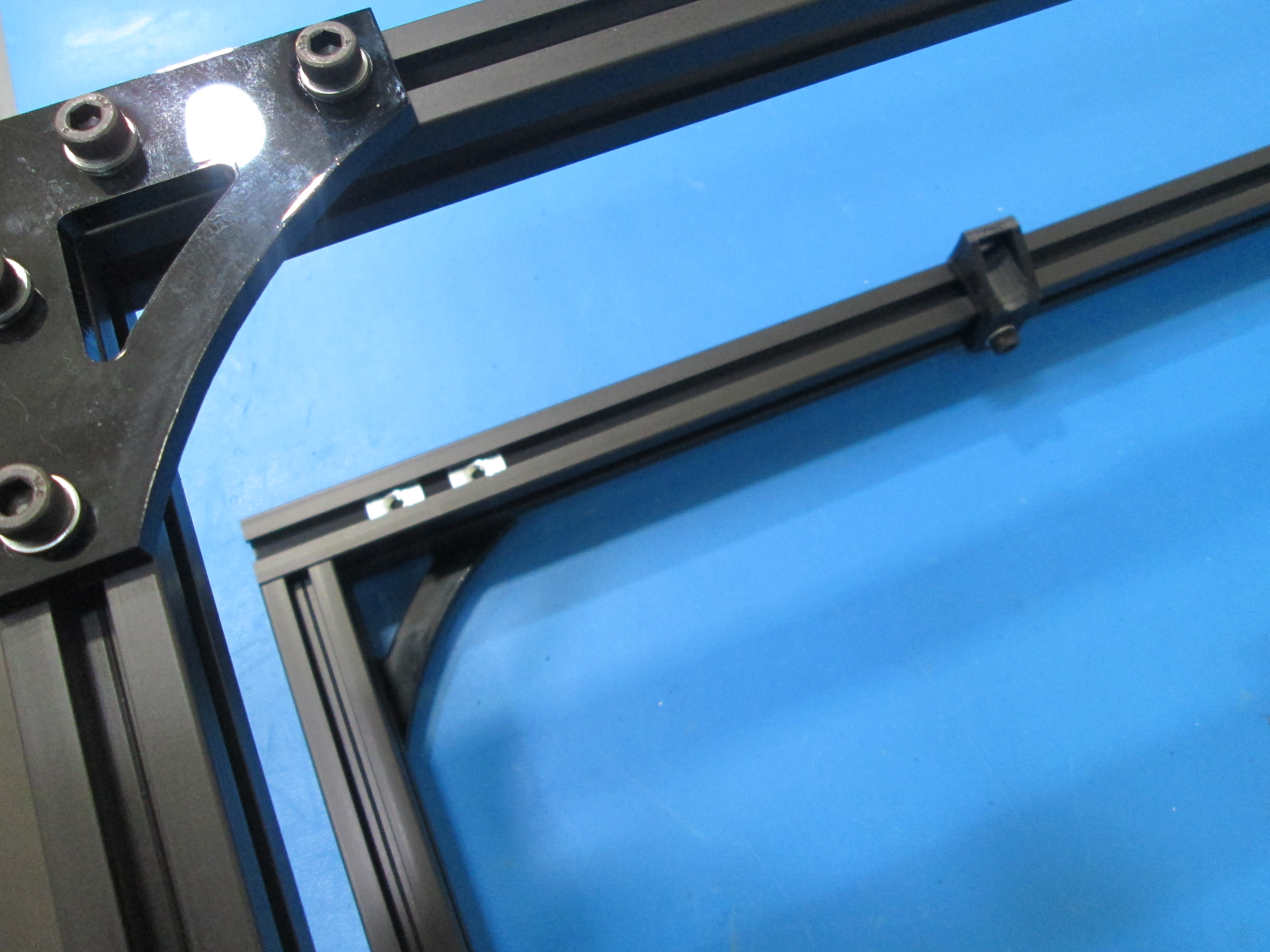
Assemble the front frame square as shown.
There is a tapped extension at the top of both the right and left extrusions.
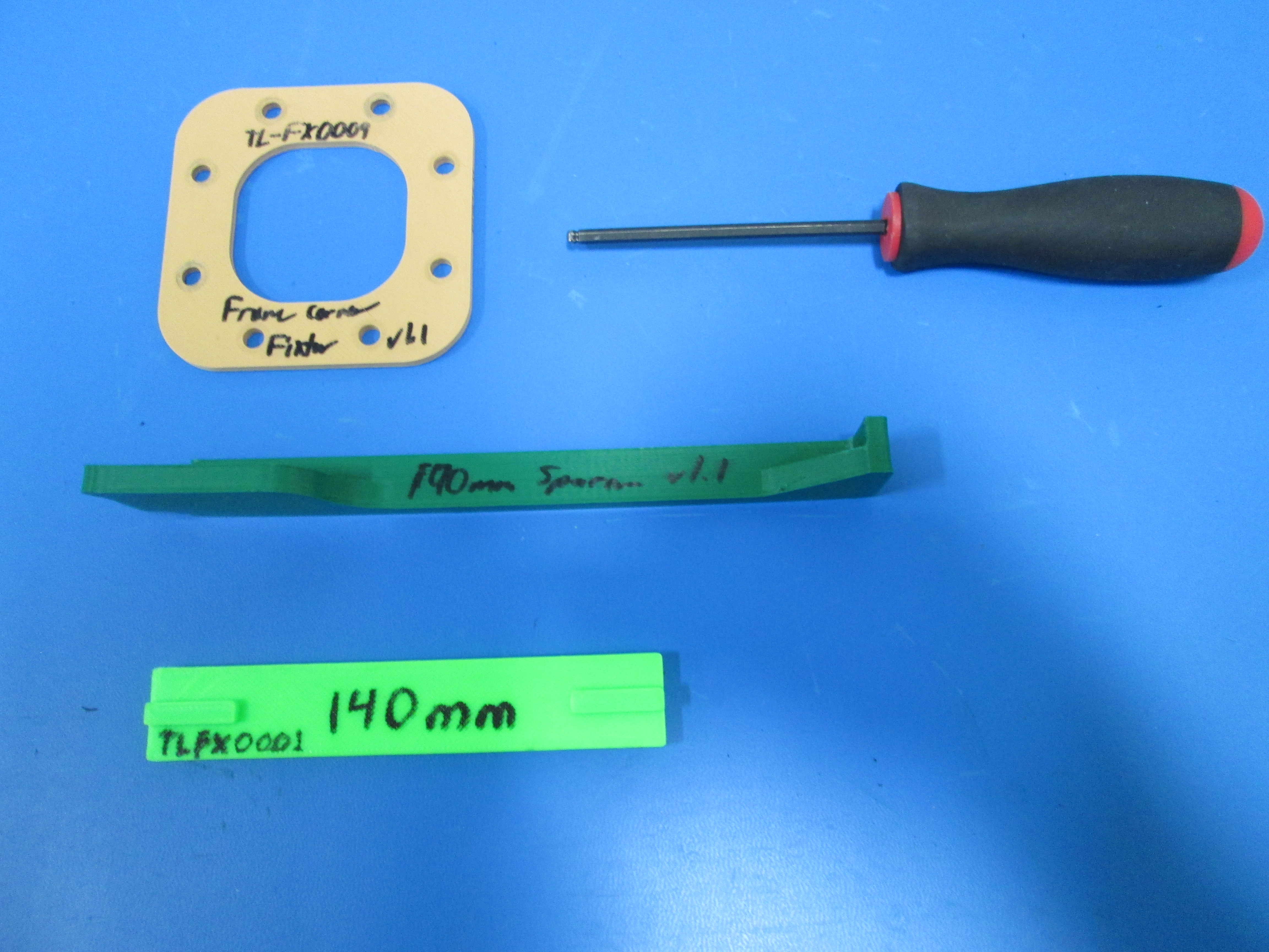
Use Fixture TL-FX0009 in the upper left corner.
Assemble using M5x10 SHCS, M5 Washers and M5 T-nuts.
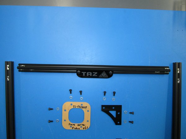
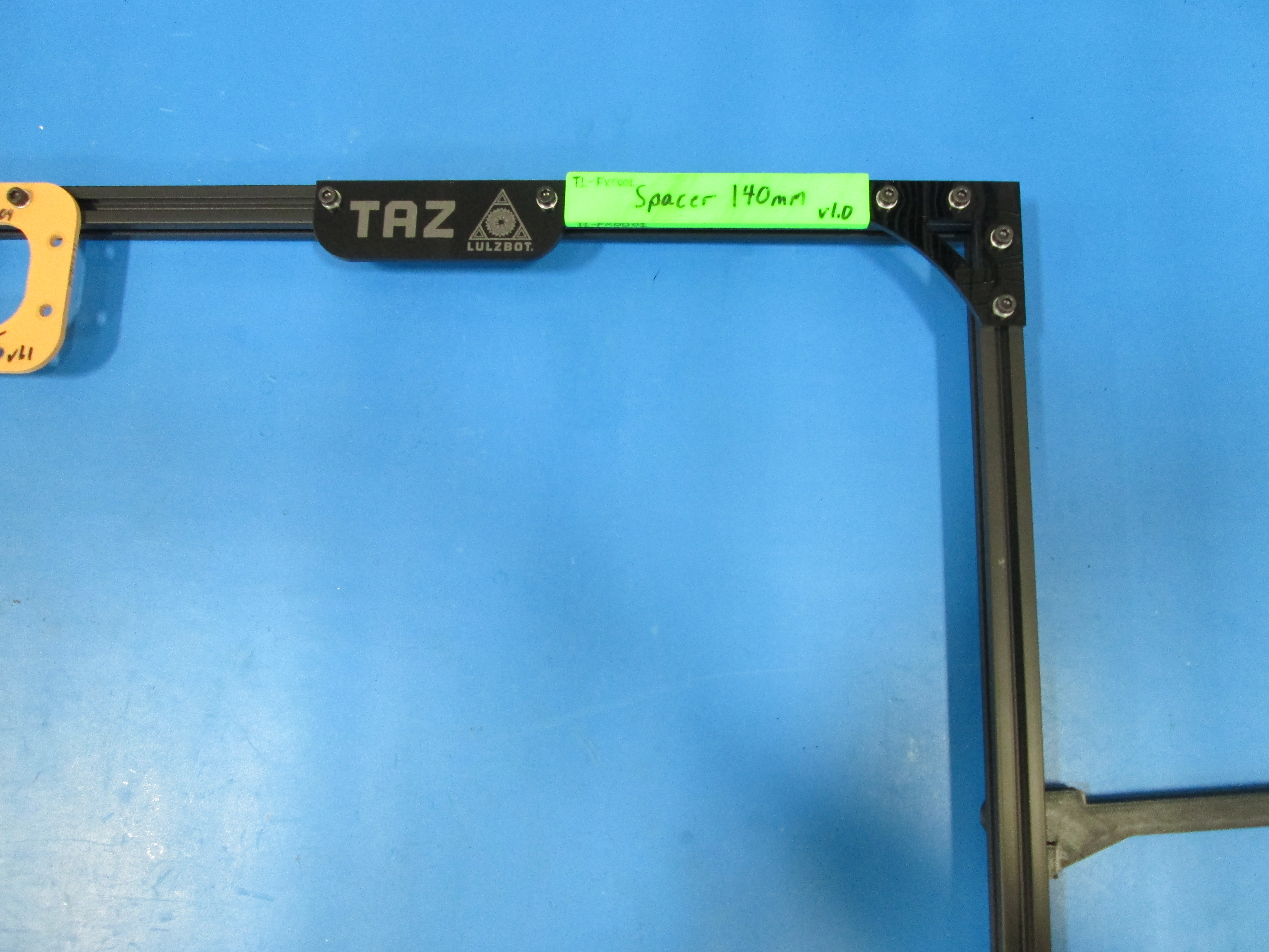
Once it is complete, you can set the location for the name plate using the TL-FX0001 fixture, or 140 mm from the right frame connector.
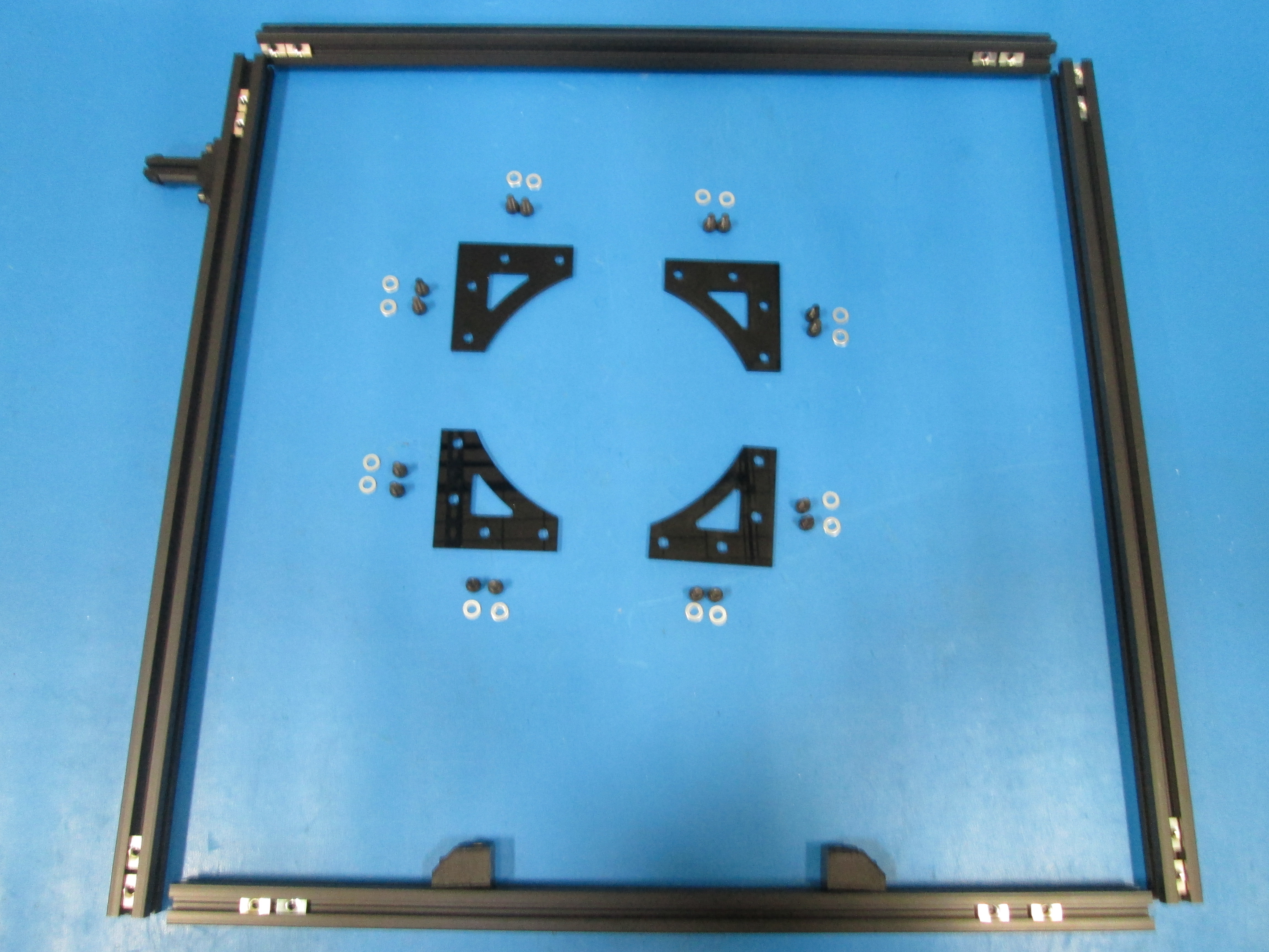
Assemble the back frame square as shown.
There is a tapped extension at the top of both the right and left extrusions.
Assemble using M5x10 SHCS, M5 Washers and M5 T-nuts.


Install Electronics case mount on the left side of the back frame square, which is the opposite side of the feed tube holder, approximately in the middle of the extrusion as shown. Use 1x M5x10 SHCS, M5 washer, and M5 T nut.
Lay the front and back frame squares together with the spacer foam.
Install Electronics case mount on the left side of the front frame square, which is the side opposite of the spool arm, approximately in the middle of the extrusion as shown. Use 1x m5x10 SHCS, M5 washer, and M5 T nut.

Install one M5 T nut in side of the back frame square and one M5 T nut in the side of the front frame square as shown.
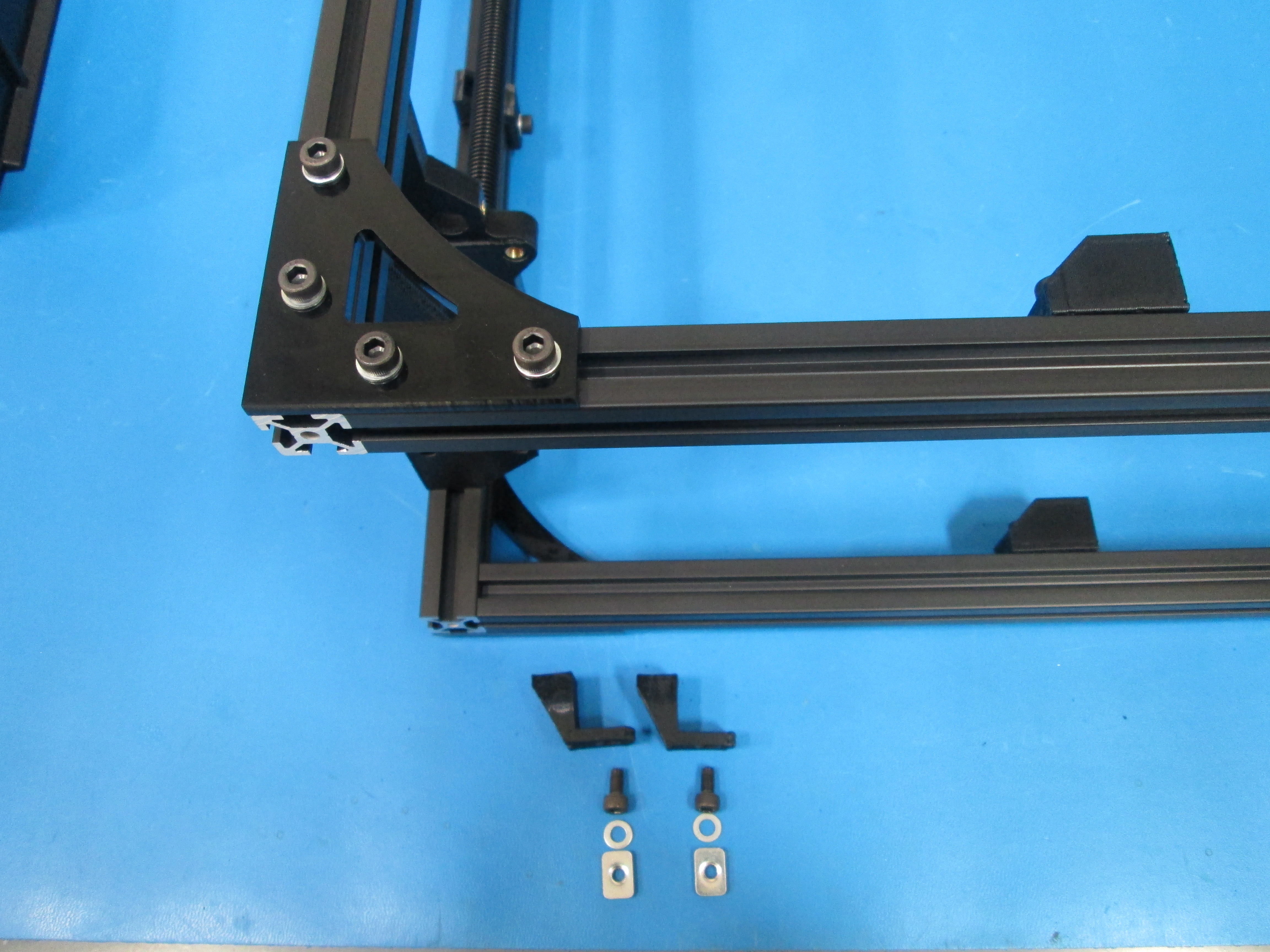
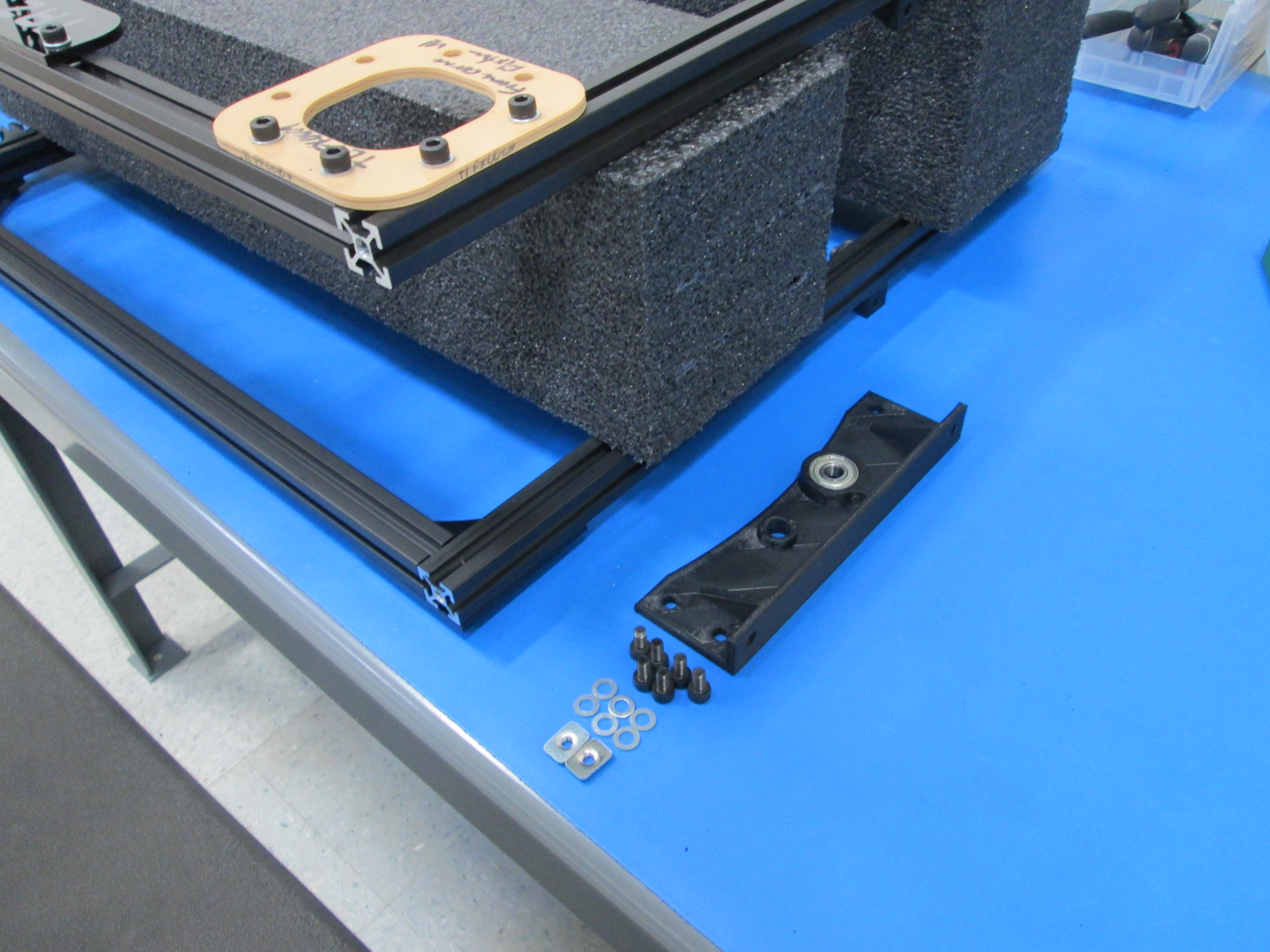
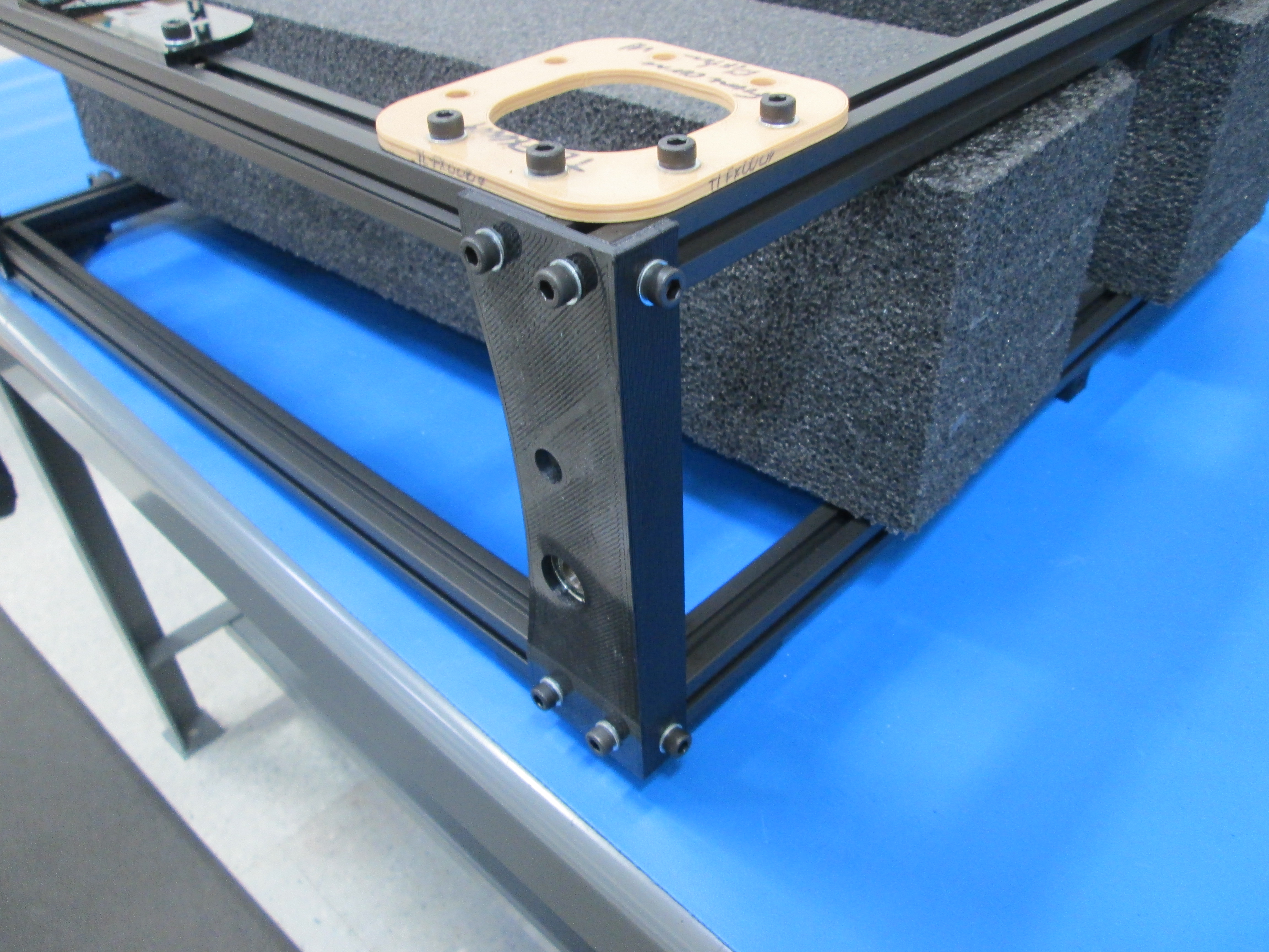
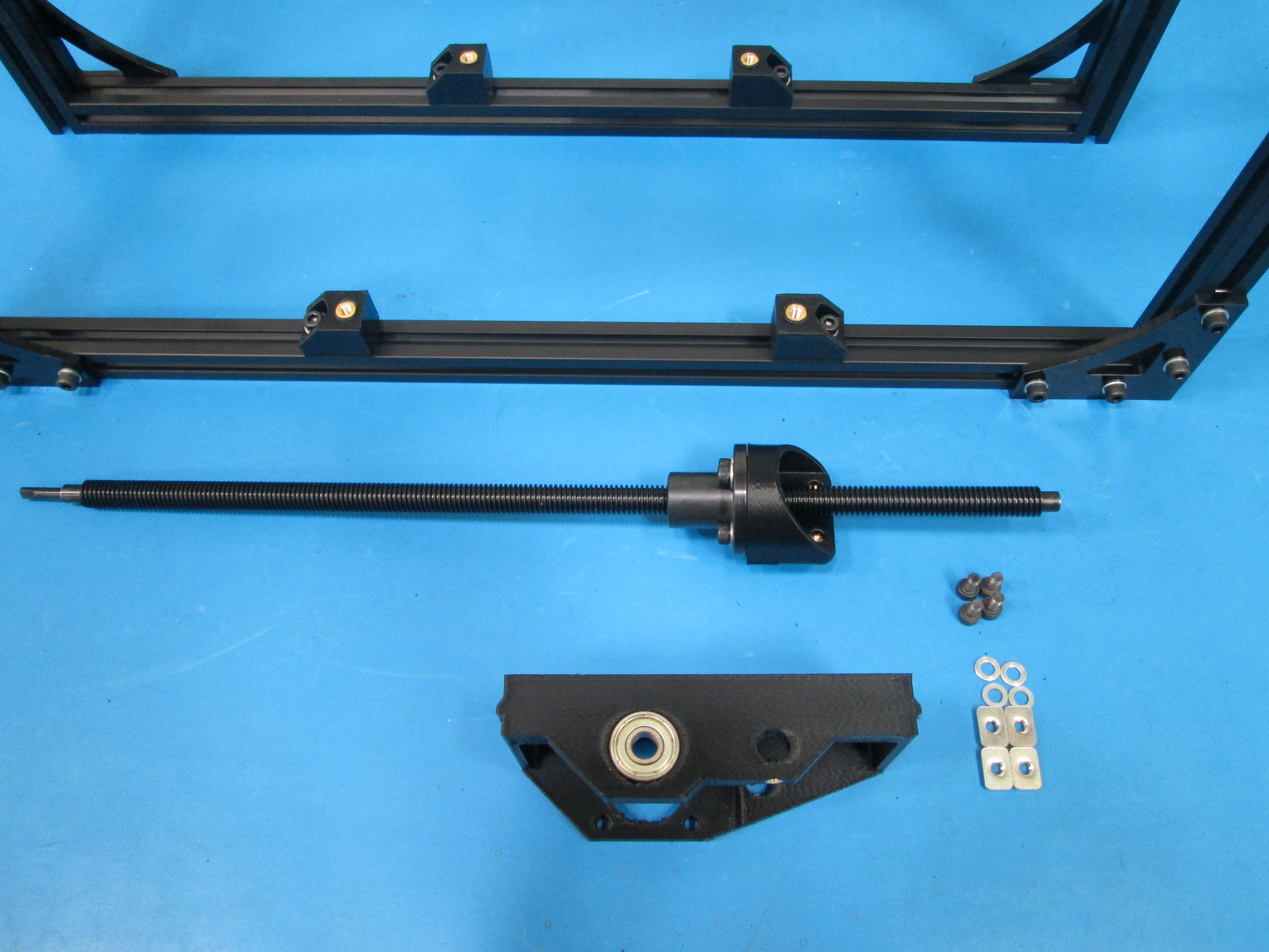
Assemble Z top drive right using 6x M5x10 SHCS and M5 washers as shown.

Install one M5 T nut in side of the back frame square and one M5 T nut in the side of the front frame square as shown.
Assemble Z top drive left using 6x M5x10 SHCS and M5 washers as shown.
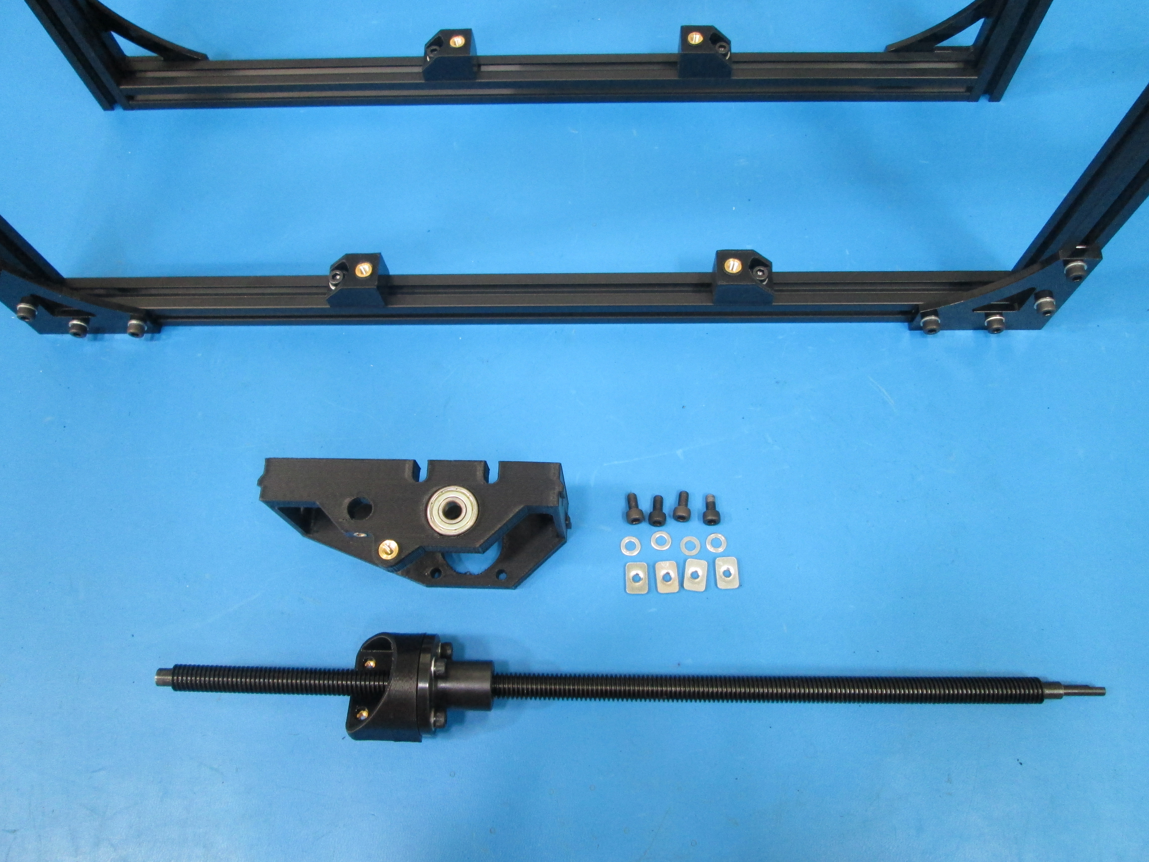
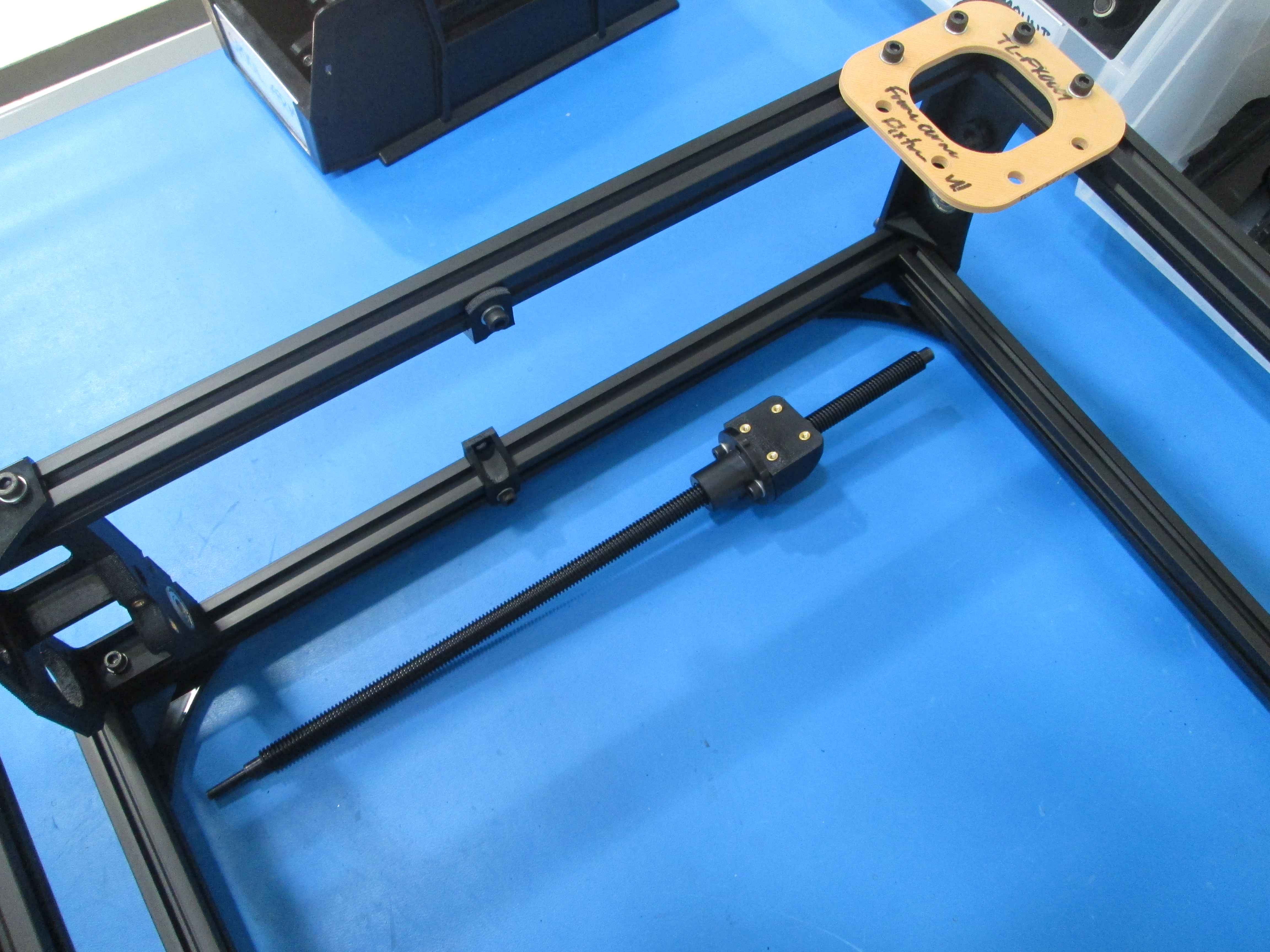
Install 4x M5 T nuts in to the extrusion, two in the back frame and two in the front frame as shown.
Use 4x M5x10 SHCS with M5 washers to secure the motor mount, the motor mount needs to be loose at this point.
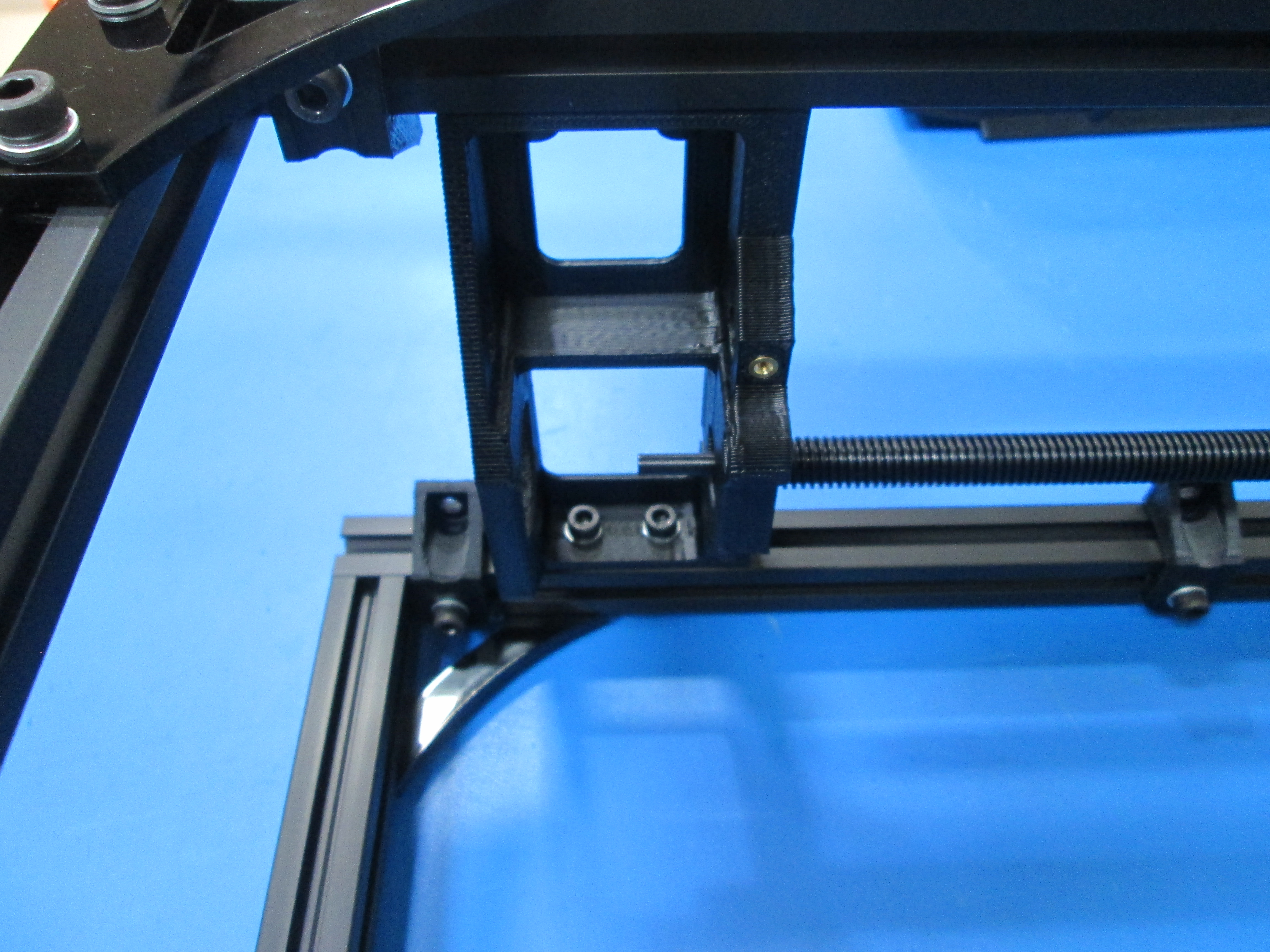
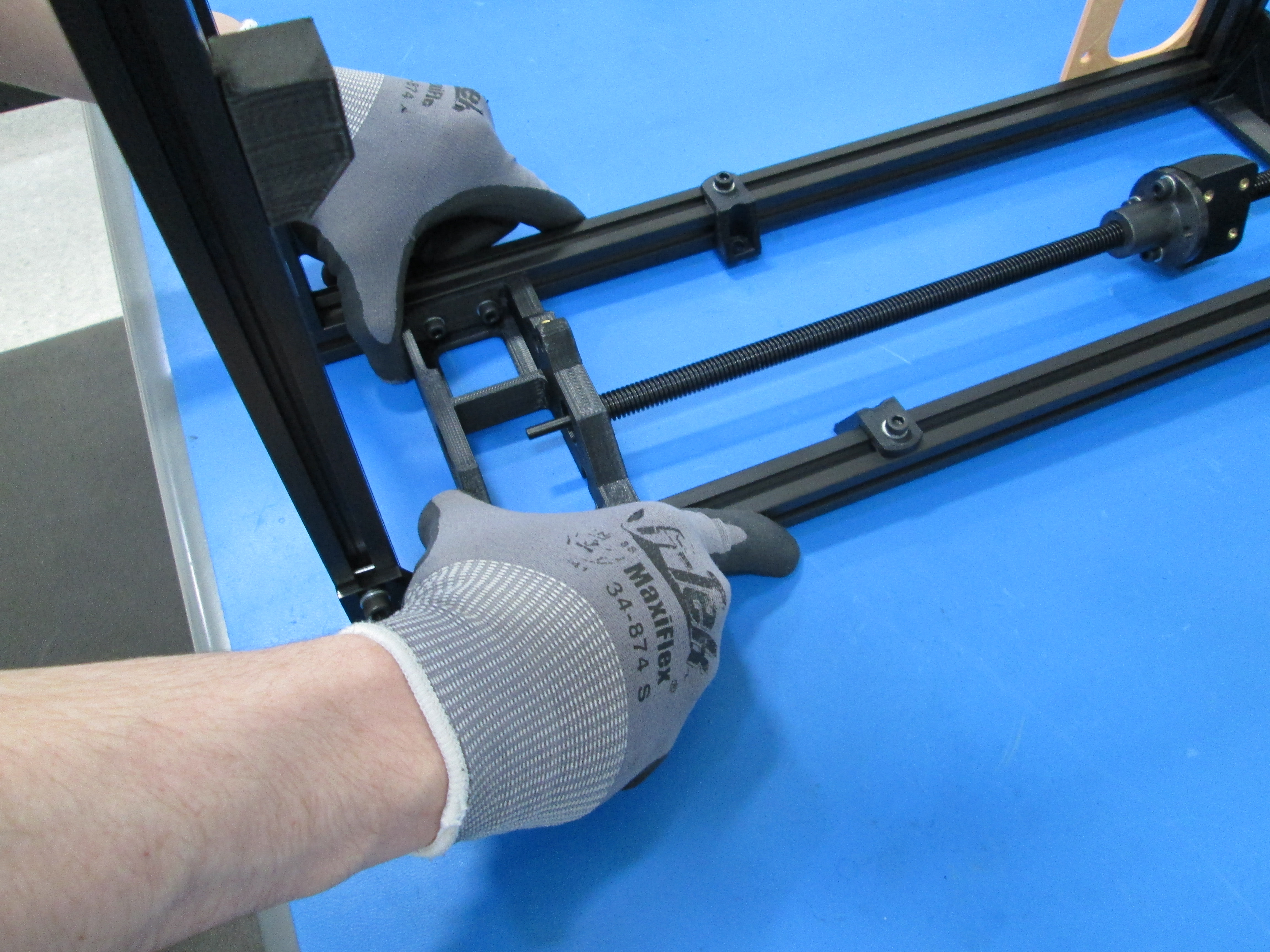
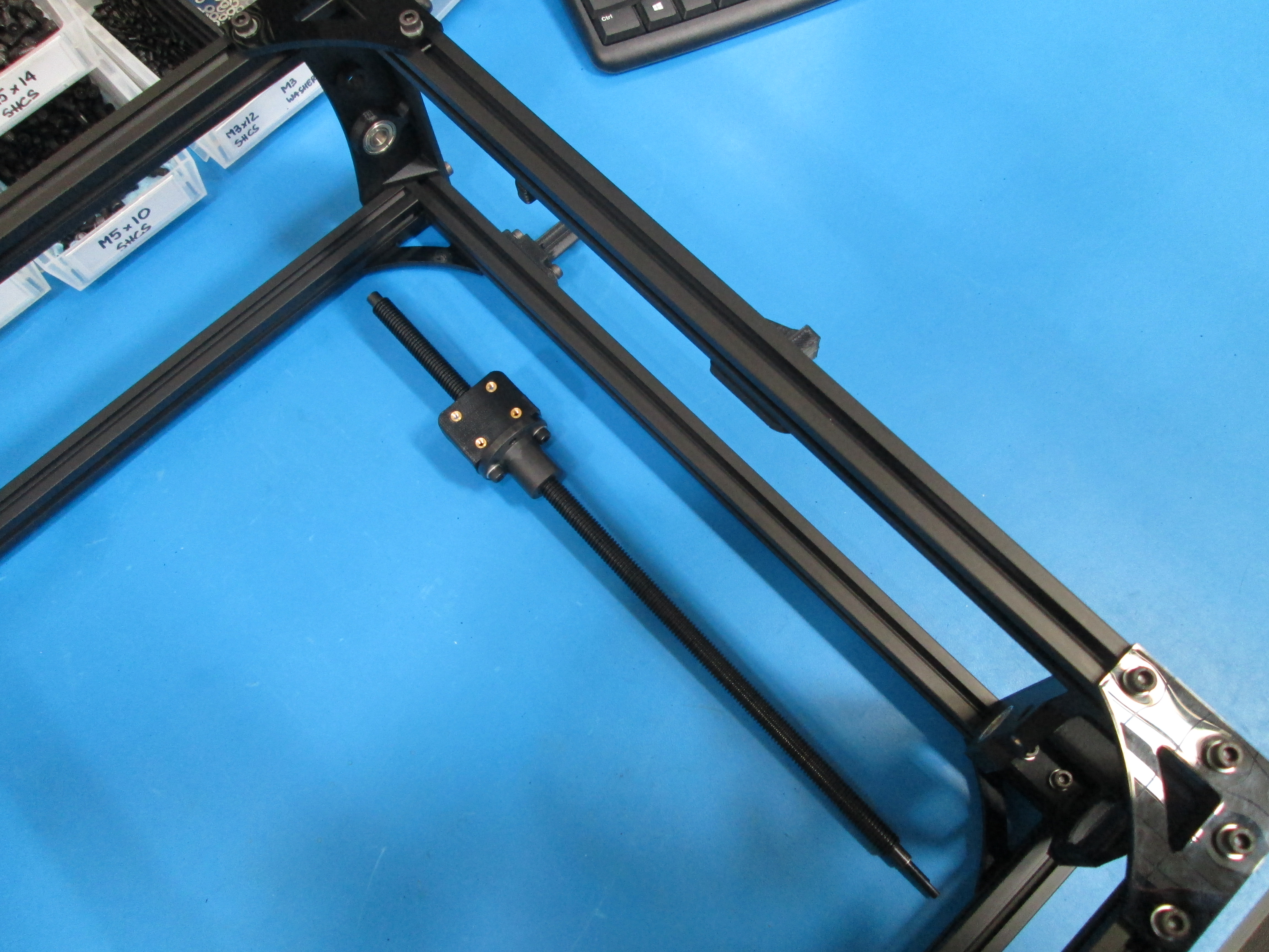
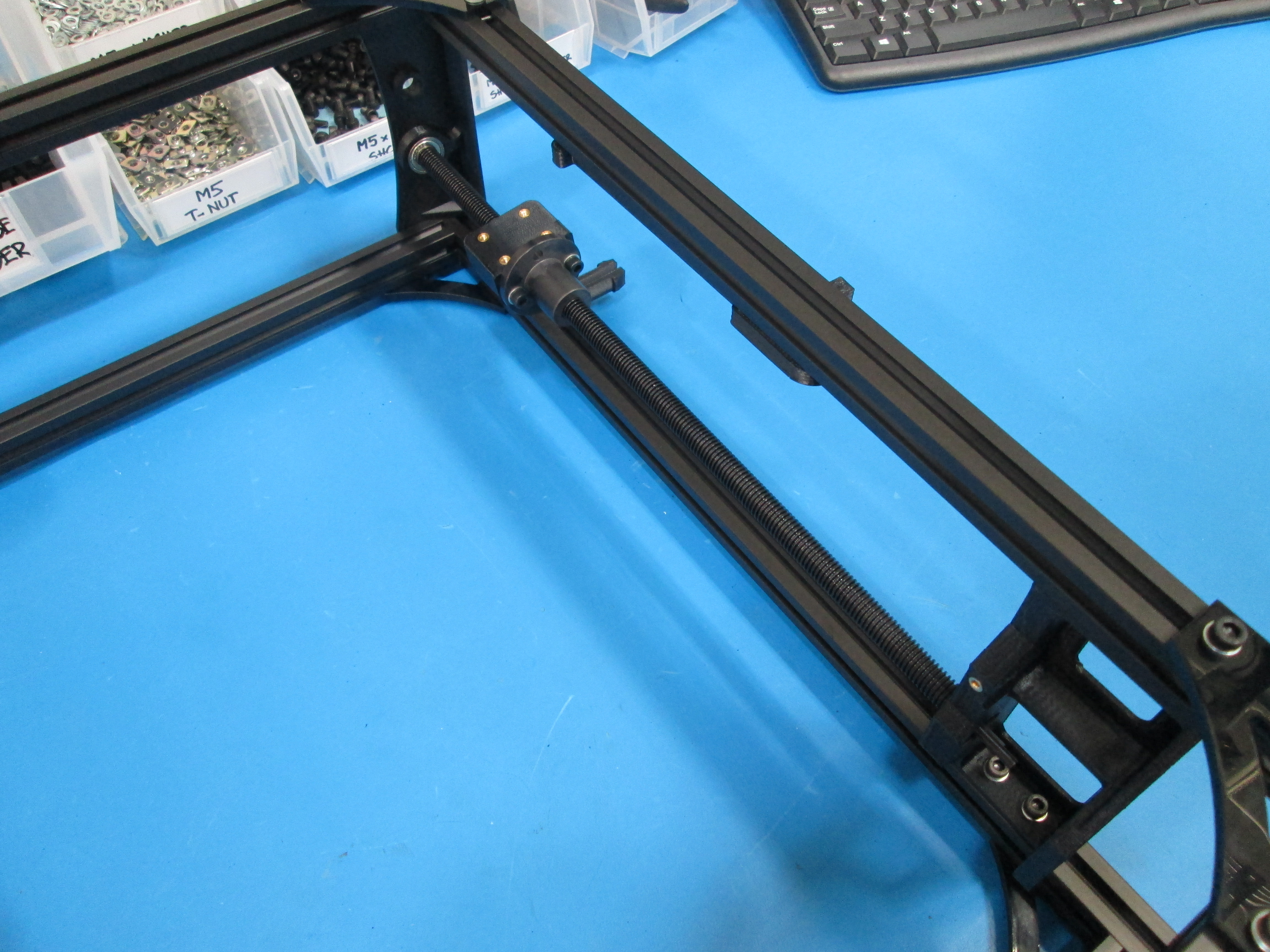
Install the drive rod into the motor mount and Z top, note orientation as shown.
Push the motor mount towards the top of the frame to ensure there is no up and down play in the drive rod.
Once the motor mount and drive rod has been pushed to the top, you can tighten the M5 bolts on the motor mount.

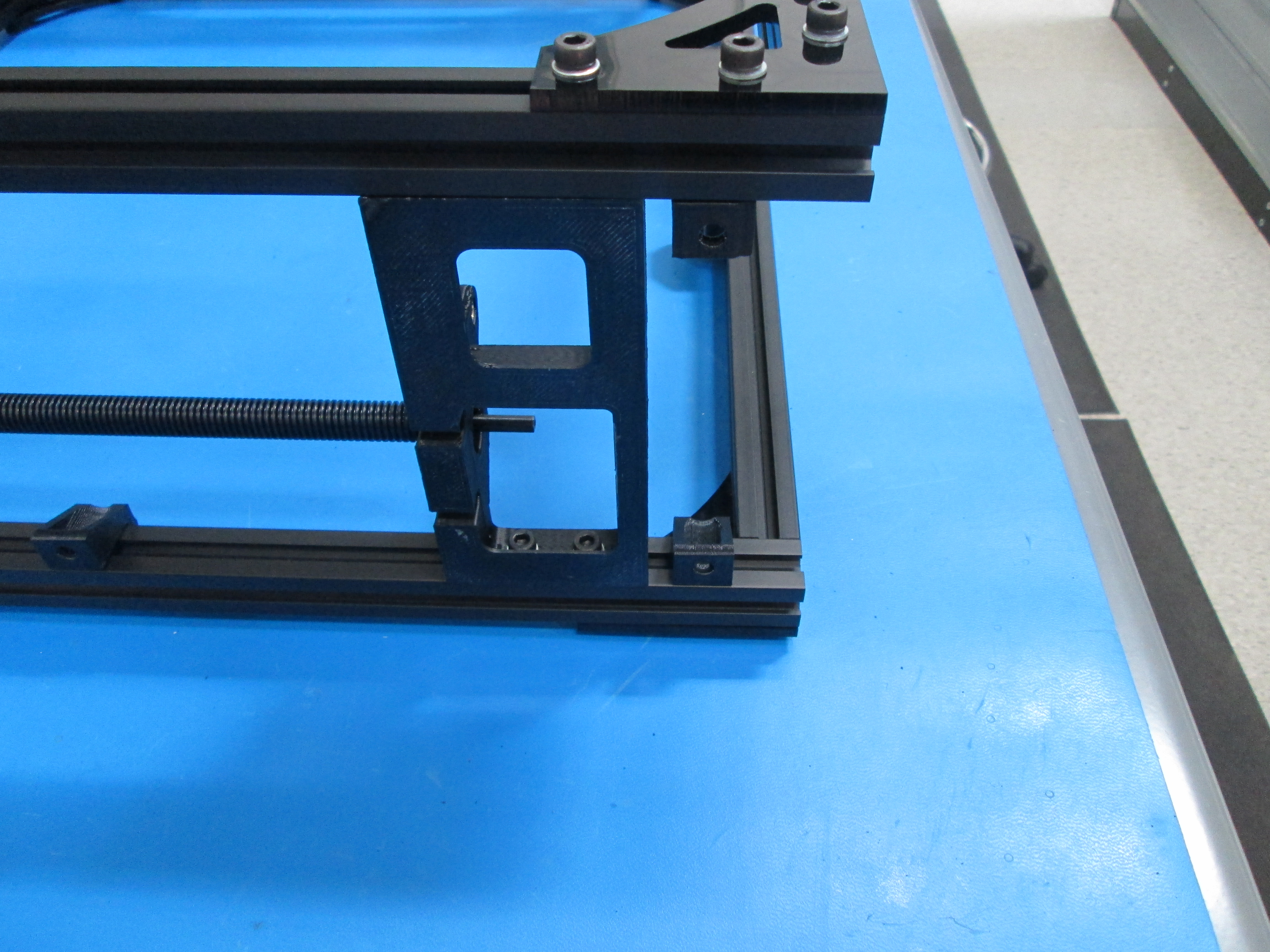
Install 4x M5 T nuts in to the extrusion, two in the back frame and two in the front frame as shown.
Use 4x M5x10 SHCS with M5 washers to secure the motor mount, the motor mount needs to be loose at this point.
Install the drive rod into the motor mount and Z top, note orientation as shown.
Push the motor mount to the top of the frame to ensure there is no up and down play in the drive rod.
Once the motor mount and drive rod has been pushed to the top, you can tighten the M5 bolts on the motor mount.

Install Electronics case mounts on the left side, one on the back frame square and one on the front frame square, using M5x10 SHCS, M5 washers, and M5 T nuts as shown.
Set the frame up on a flat surface.
Close any gaps there may be at the ends of the extrusions.
Make sure all parts are straight on the assembly with edges flush with the extrusion.
Make sure all the bolts are tight once frame is confirmed square.