Open HardwareAssembly Instructions
Guides for installation and assembly of the LulzBot line of products made by FAME 3D LLC.
Guides for installation and assembly of the LulzBot line of products made by FAME 3D LLC.
16x- [HD-BT0073] M5x10 BHCS, Black-Oxide
2x- [HD-BT0157] M3x8 SHCS, Black-Oxide
2x- [HD-BT0266] M4x30 HHCS, Black-Oxide
10x- [HD-BT0272] M5x20 BHCS, Black-Oxide
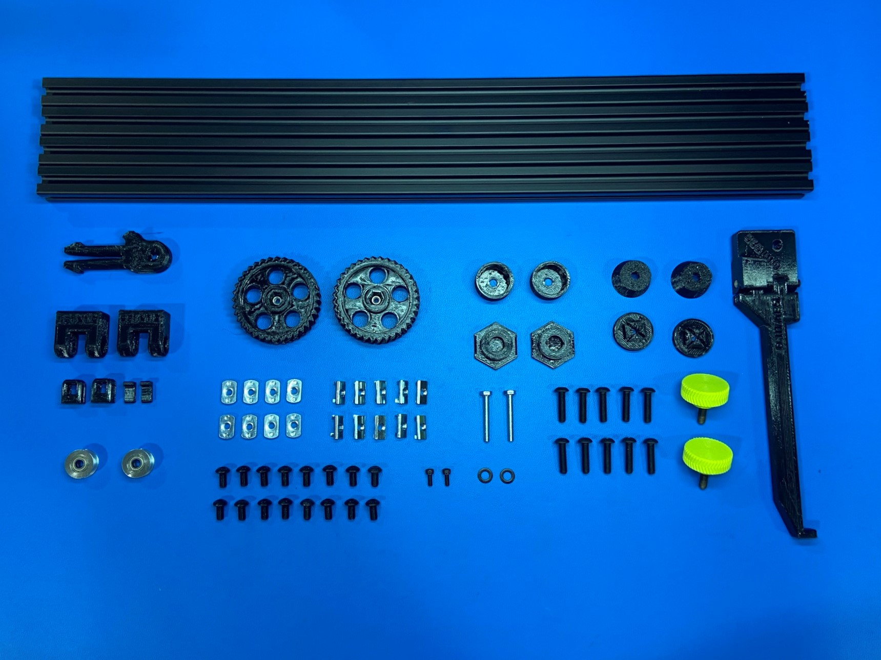
4x- [HD-EX0062] T-Slot Extrusion 500mm
2x- [HD-MS0593] 5mm Smooth Bore Idler
10x- [HD-NT0044] Post Assembly M5 T-Nut
8x- [HD-NT0053] M5 T-Slot Nut
2x- [HD-WA0040] M5 Washer
1x- [PP-GP0531] Z Belt Tensioner
1x- [PP-GP0532] Belt Clamp
1x- [PP-GP0557] XYZ Tensioner Knob
1x- [PP-GP0558] Z Level Printer Foot
1x- [PP-GP0567] Z Adjustable Frame Foot Top
1x- [PP-GP0568] Z Adjustable Frame Foot Bottom
1x- [PP-GP0587] M5 28mm DIA Press Fit Knob
1x- [PP-GP0594] Feed Tube Holder Mount
1x- [PP-GP0646] Flexy Foot Bottom
1x- [PP-GP0649] Belt Clamp Sled
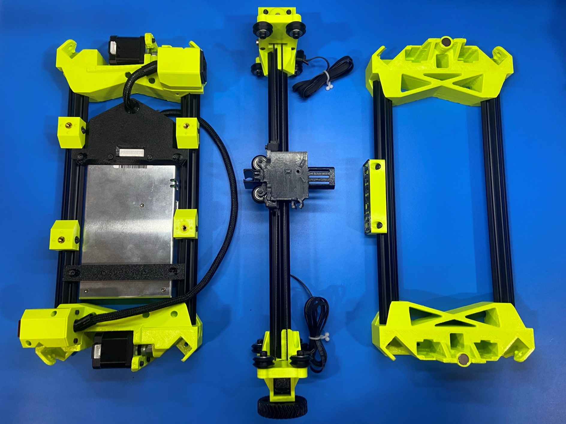

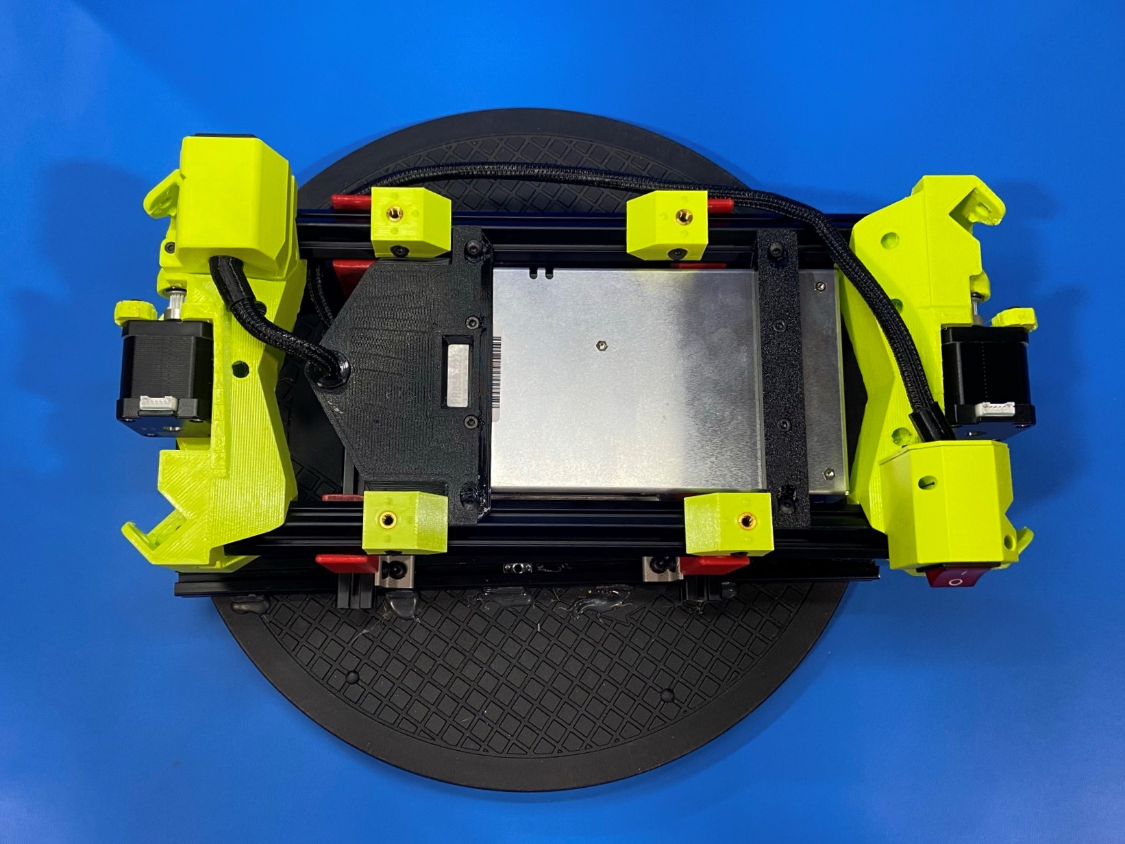
Place the Z Lower assembly inside the fixture that is fastened to the turntable.
Then place 4x T-slot extrusions 500mm [HD-EX0062] inside the four square slots located on the ends of the right and left Z lowers.
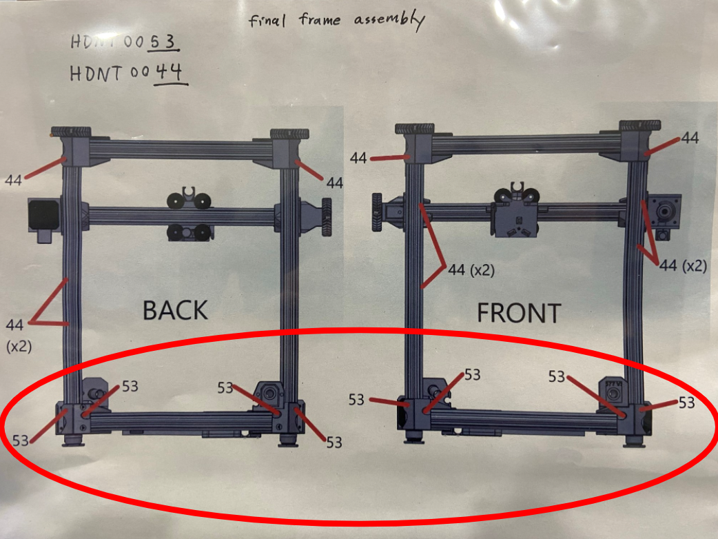
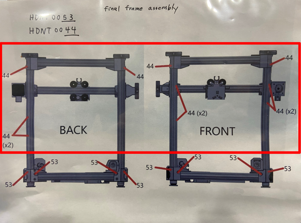
Following [reference#1] slide 8x M5 T-slot nuts [HD-NT0053] inside the four extrusions.
Next follow [reference#2] to slide 10x post assembly T-slot nuts [HD-NT0044] inside the four extrusions.
Note: You may need to bend the tabs to slide the nuts inside the extrusions.
Using 8x M5x10 BHCS [HD-BT0073] secure the extrusions to the Z lowers, making sure to leave the bolts loose so the extrusion can be properly seated inside the Z lower in a later step.
Note: You may need to move the HD-BT0053 T-nuts around to get the bolt started.
Once the extrusions are some what secured to the Z lower slide the X axis assembly in-between the extrusions making sure the BL touch mount is facing down and that the tool head mount is facing the front of the printer. The X motor should also be on the same side as the power switch.
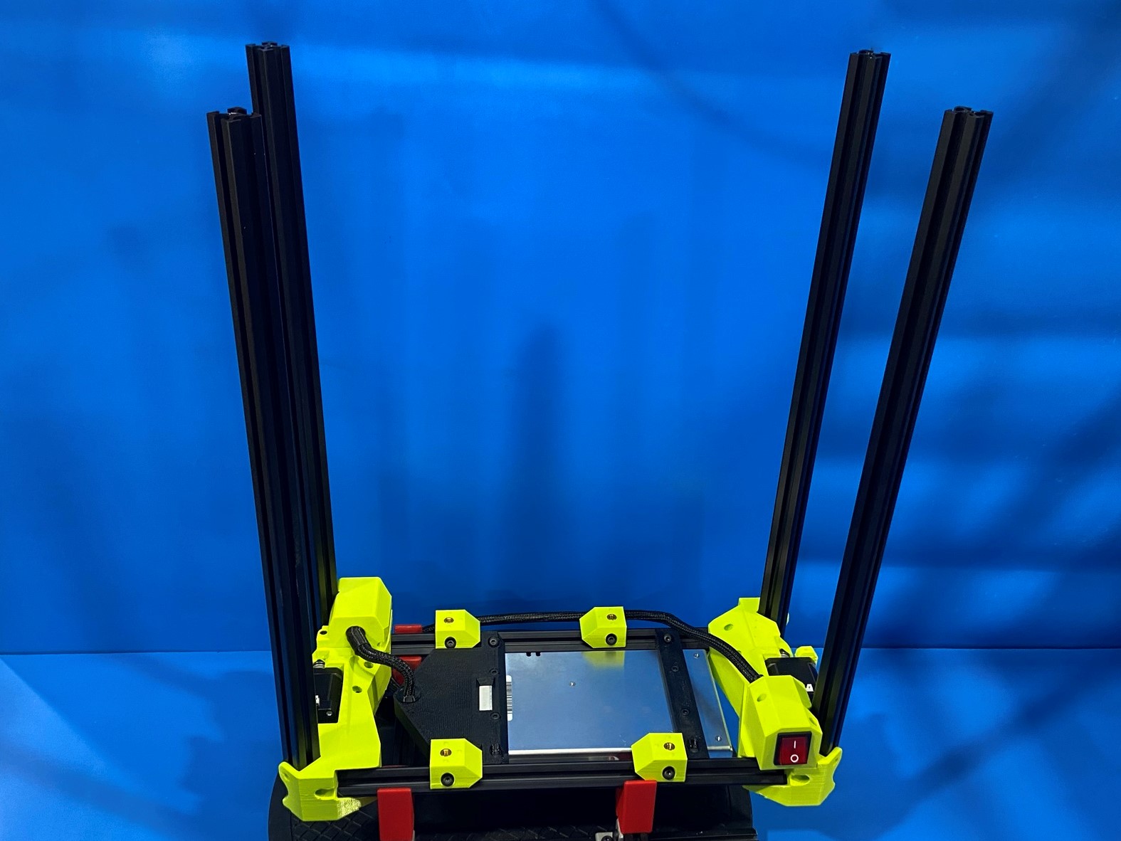

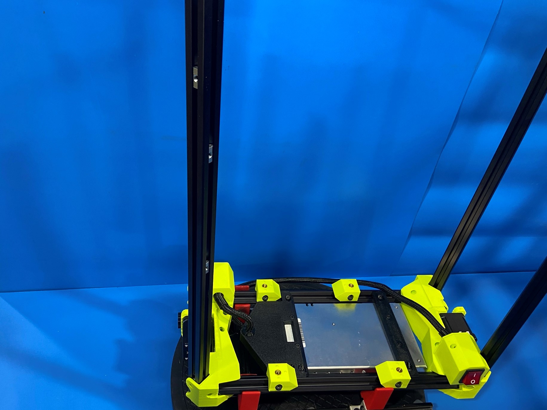
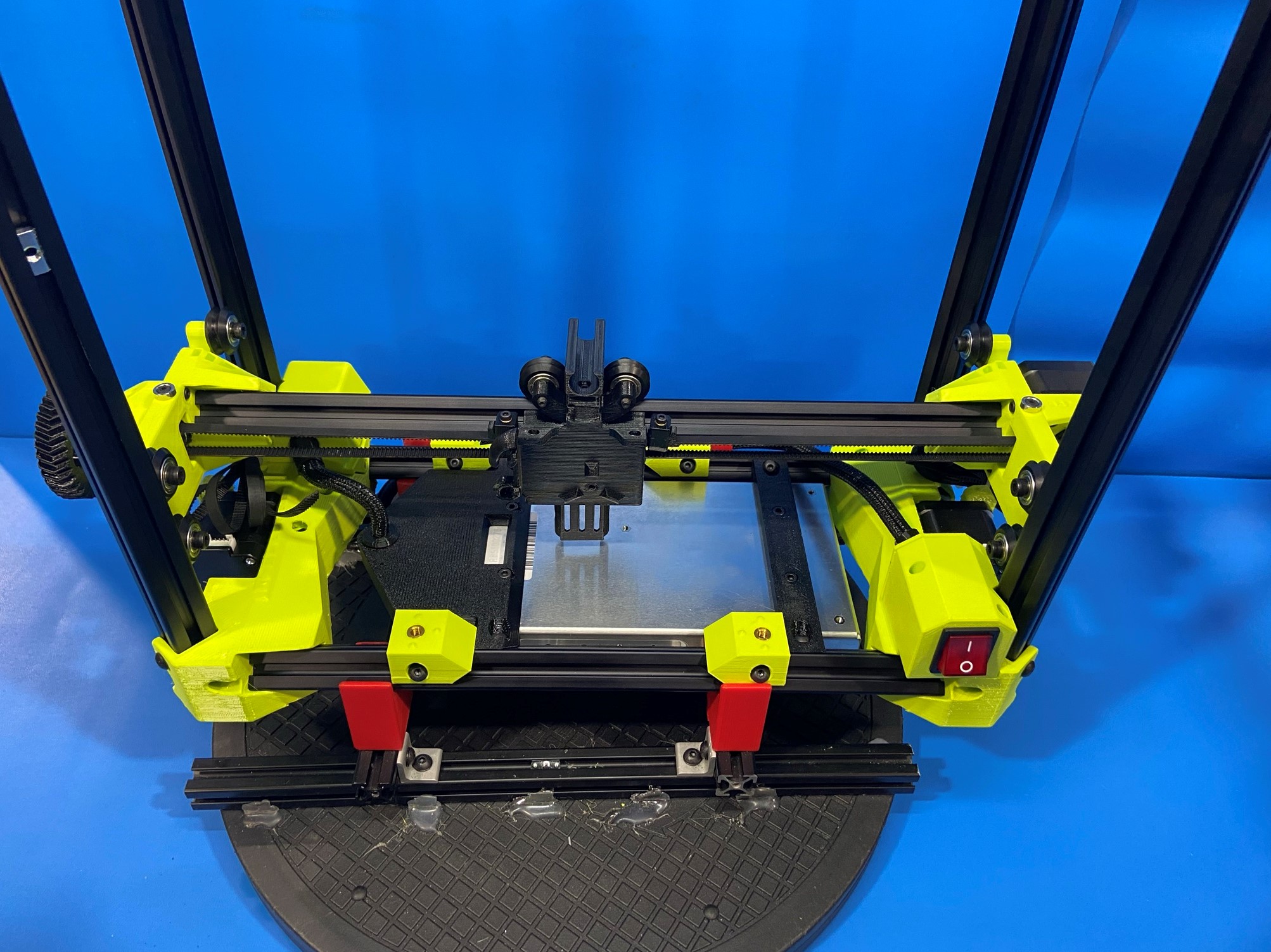
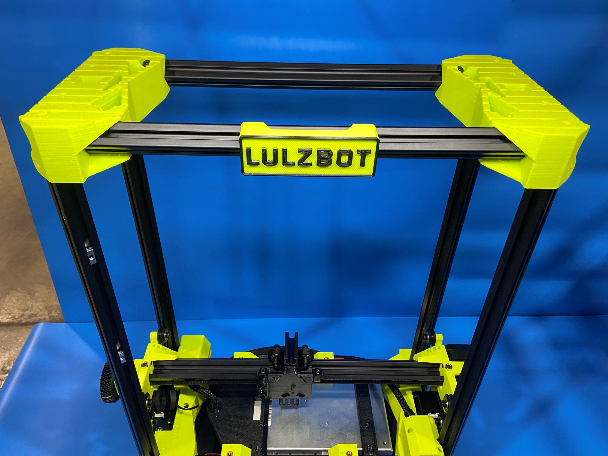
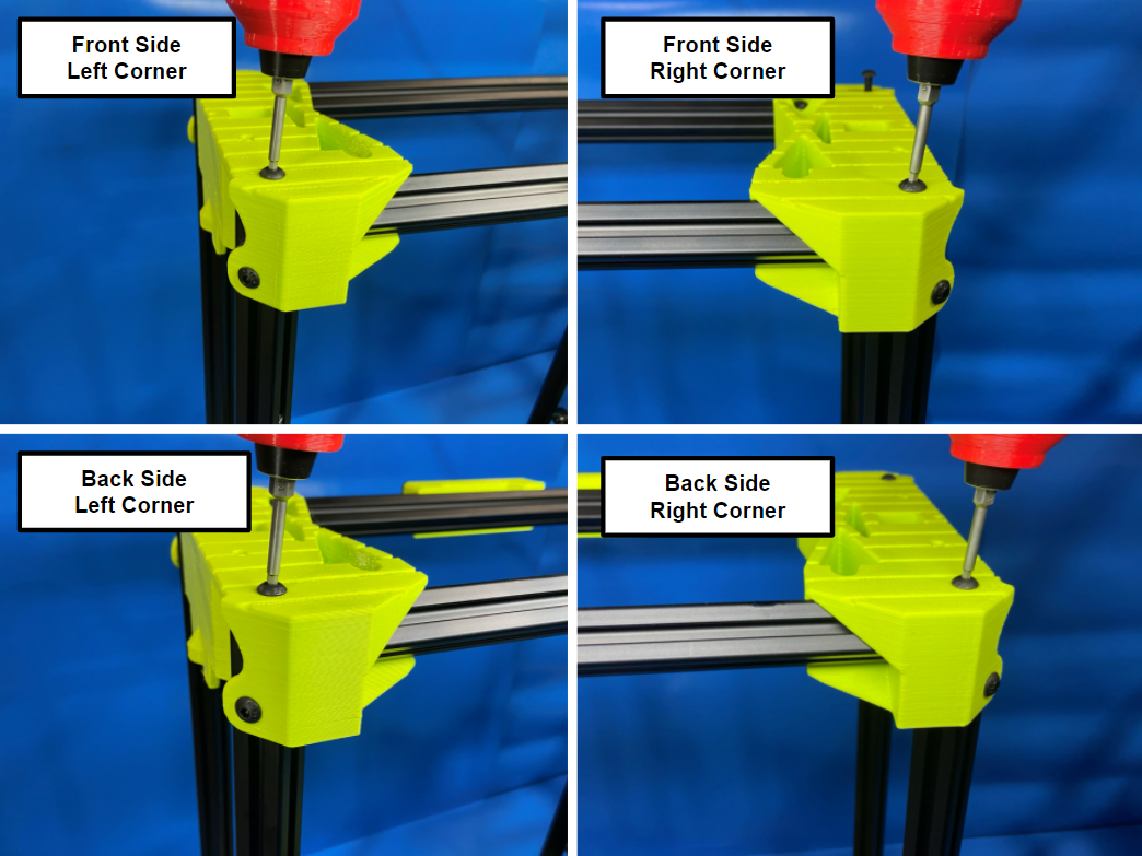
Place the Z upper assembly on top of the four extrusions making sure the extrusion are aligned with the four square slots on the Z uppers.
Note: You may need the mallet to properly place the Z upper.
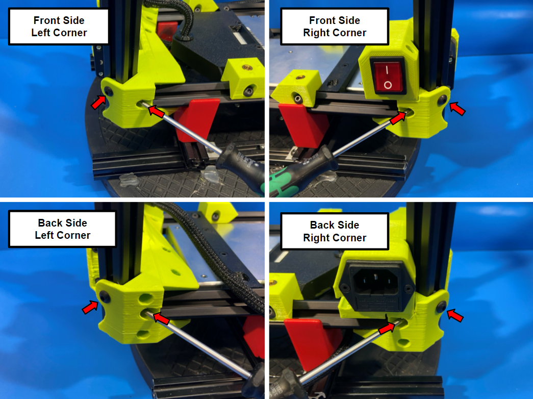
Then slide the post assembly T-slot nut [HD-NT0044] under the tab with a hole in it located on the end of the Z upper, repeat for the other corners.
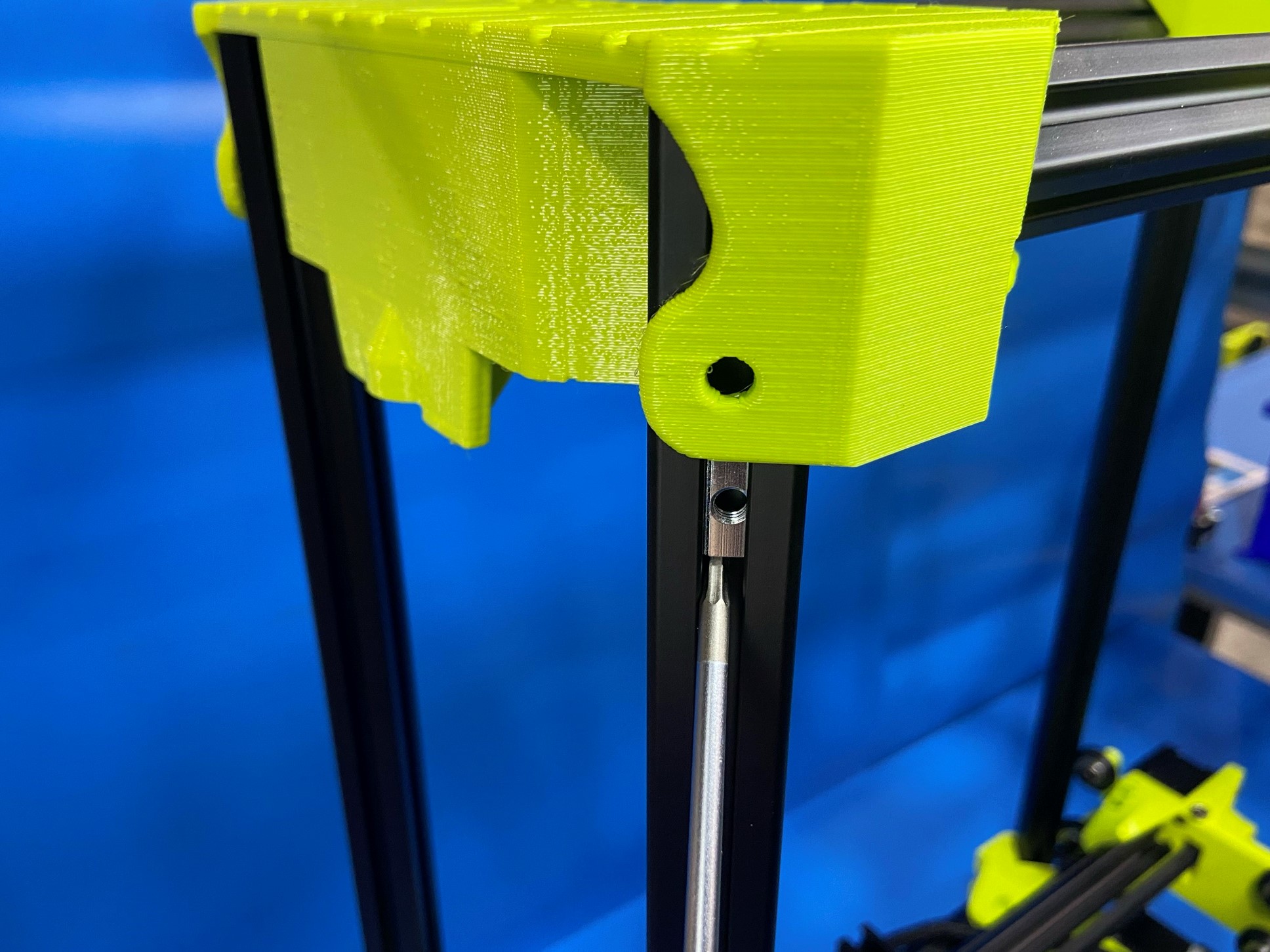
Now using a Hex screw driver loosely fasten 4x M5x10 BHCS [HD-BT0073] to the T-slot nuts securing the Z uppers.
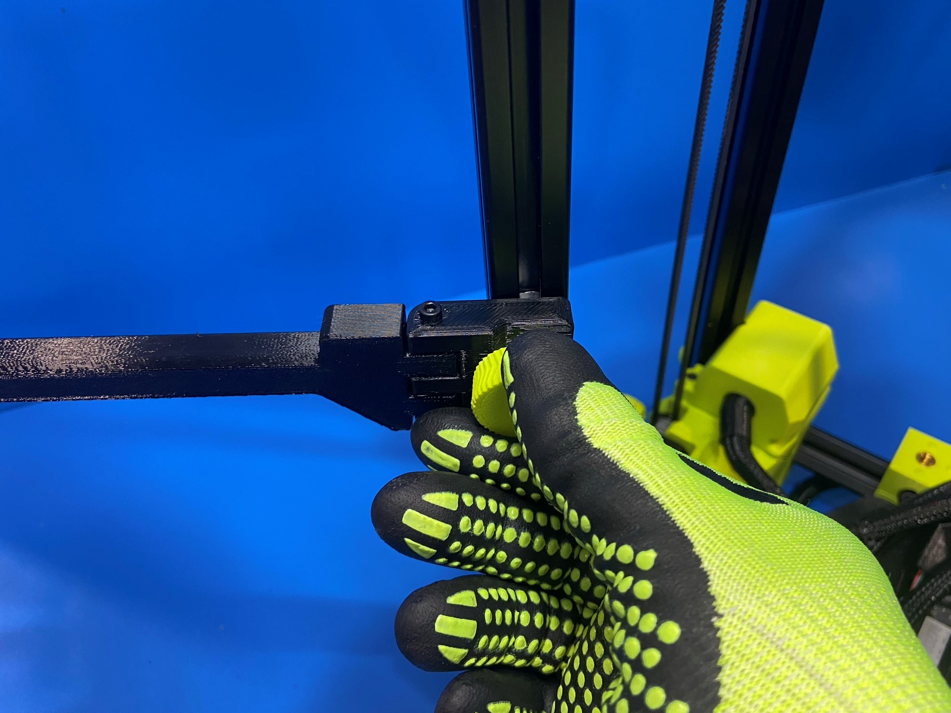
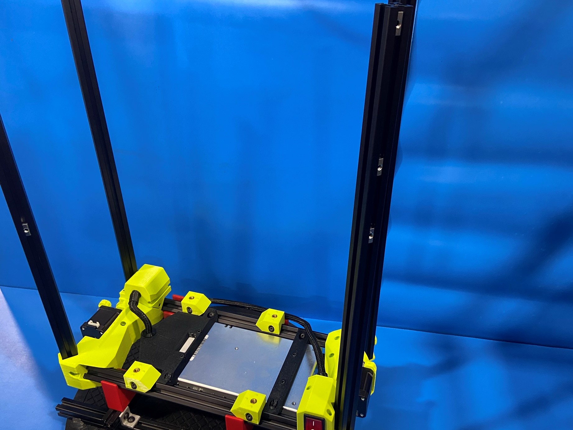
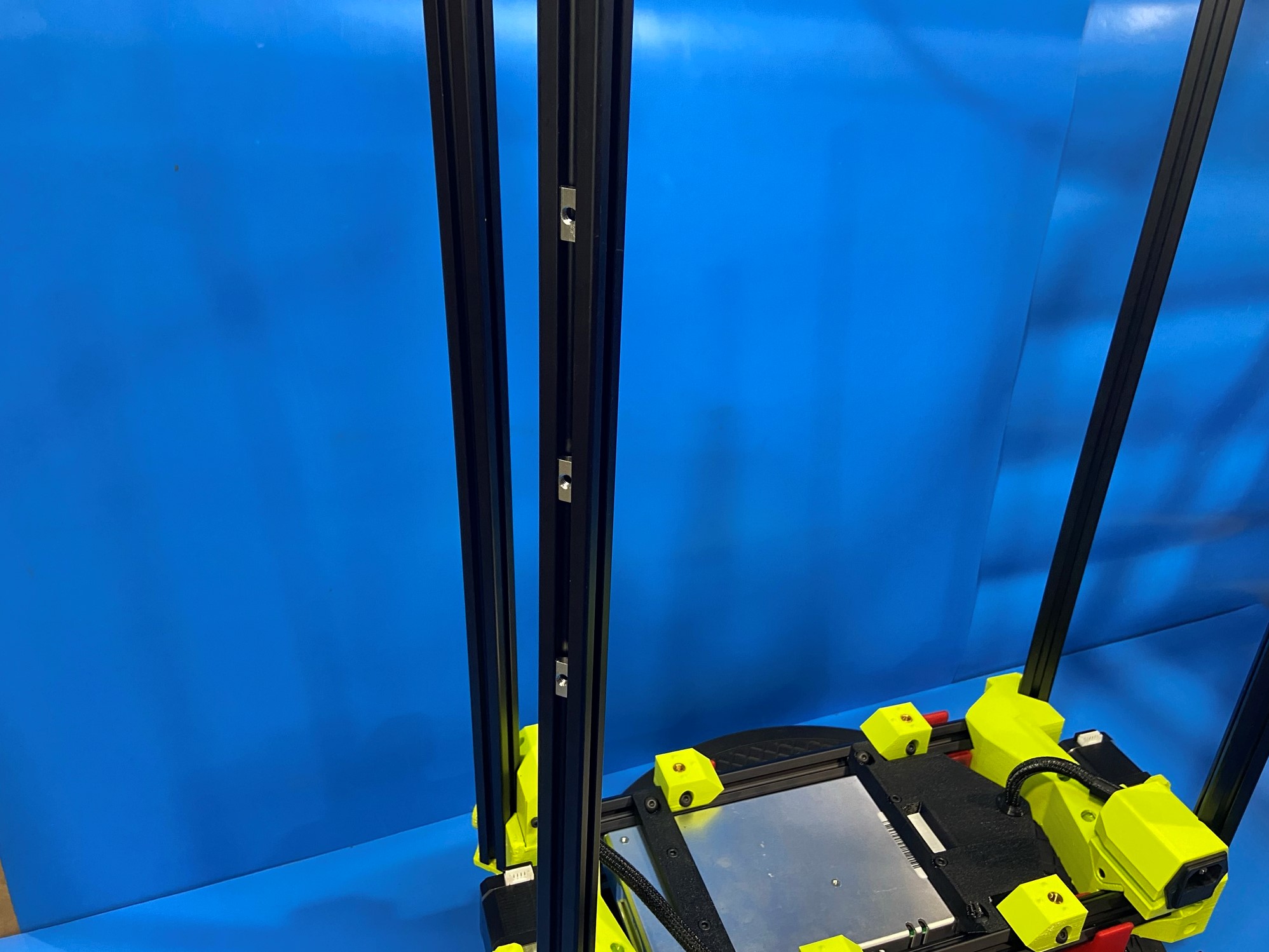
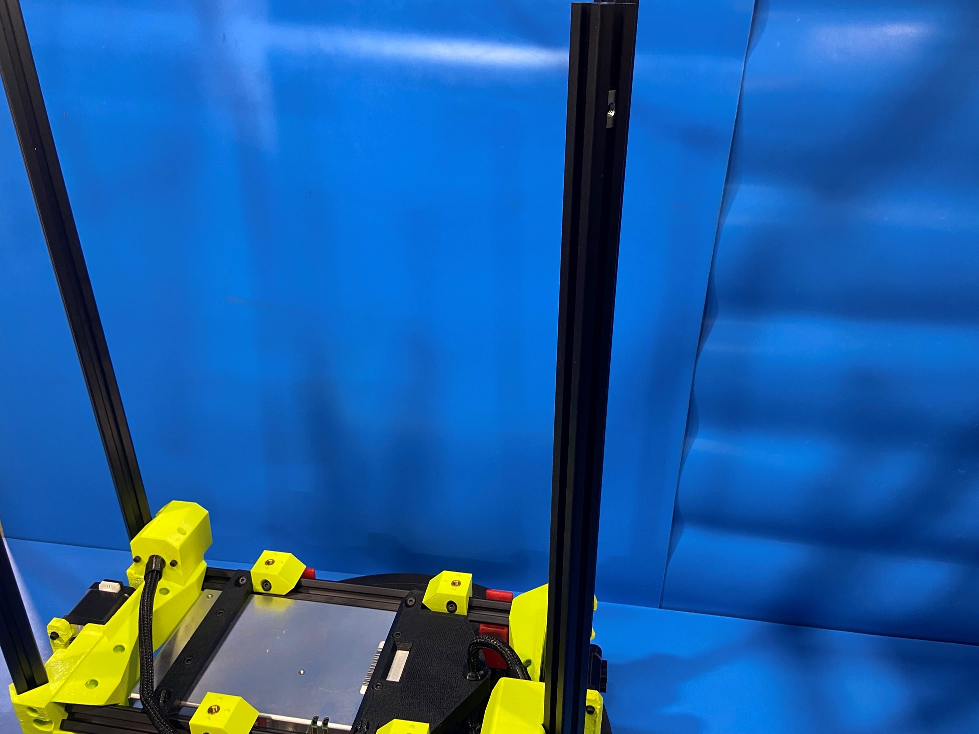
Again using a Hex screw driver start fastening 1x M5x20 BHCS [HD-BT0272] into the extrusions, repeat for the other extrusions.
Then use the drill to tighten the 4x [HD-BT0272] to the extrusions.
Again use the drill to tighten the 4x [HD-BT0073] to the T-slot nuts.


Flip the printer over so that the Z upper is placed inside the fixture.
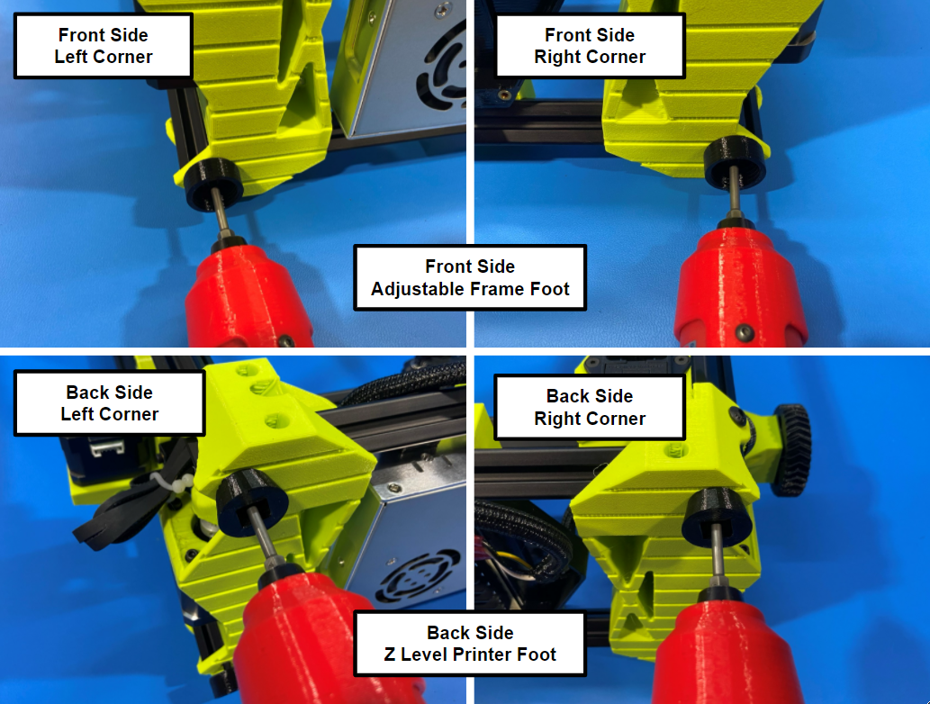
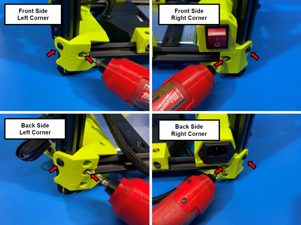
Use a Hex screw driver along with 2x M5x20 BHCS [HD-BT0272] to start attaching 2x Adjustable frame foot bottoms [PP-GP0568] to the two extrusions on the front side of the printer (side with the power switch).
Then repeat the process for the back two extrusions and 2x Z level printer feet [PP-GP0558]
Then use the drill to secure the printer feet to the four extrusions.
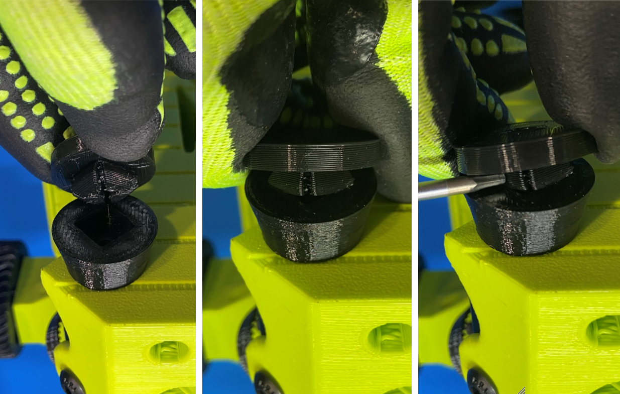
Now take 1x flexy foot bottom [PP-GP0646] and slide a corner into the Z level printer foot making sure the parts align.
Then use a screw driver to push on the side of the flexy foot bottom so that you can push down and snap the flexy foot bottom in place.
Repeat for the other Z level printer foot.
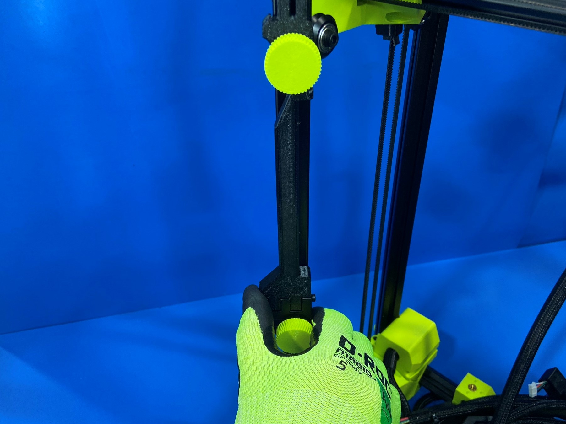
Then take 1x Z adjustable frame foot top [PP-GP0567] and screw it into one of the Z adjustable frame foot bottoms and repeat for the other side.
Now use the drill to fasten the 8x [HD-BT0073] to the T-slot nuts securing the extrusions to the Z lowers.

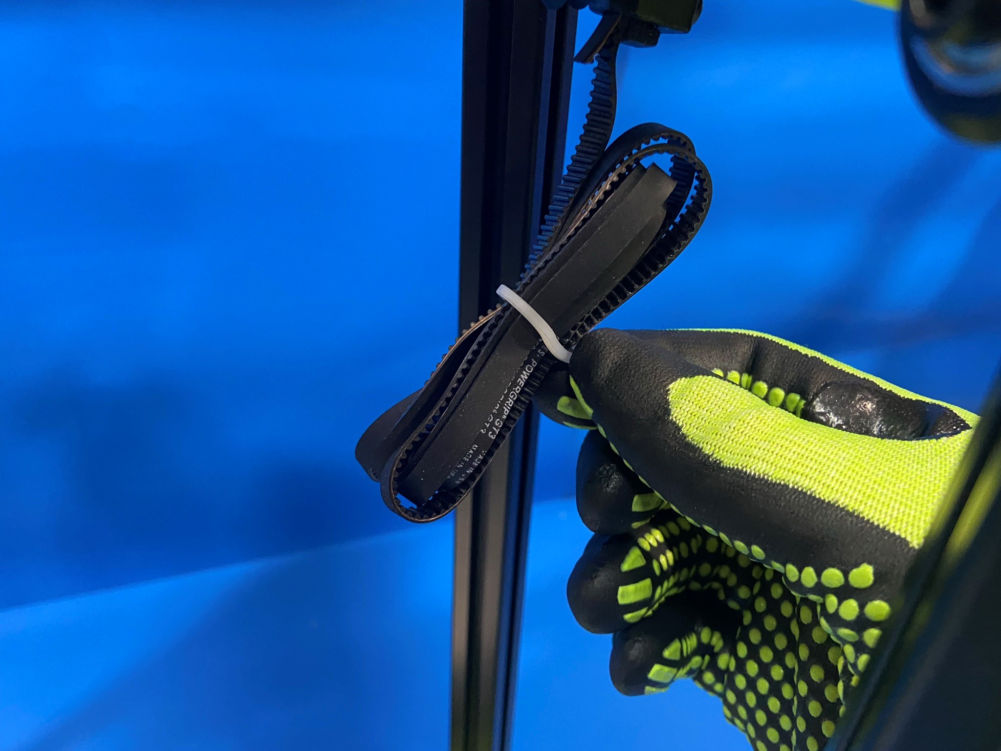
Start by removing both clips that are around the Z belts on the X axis assembly.
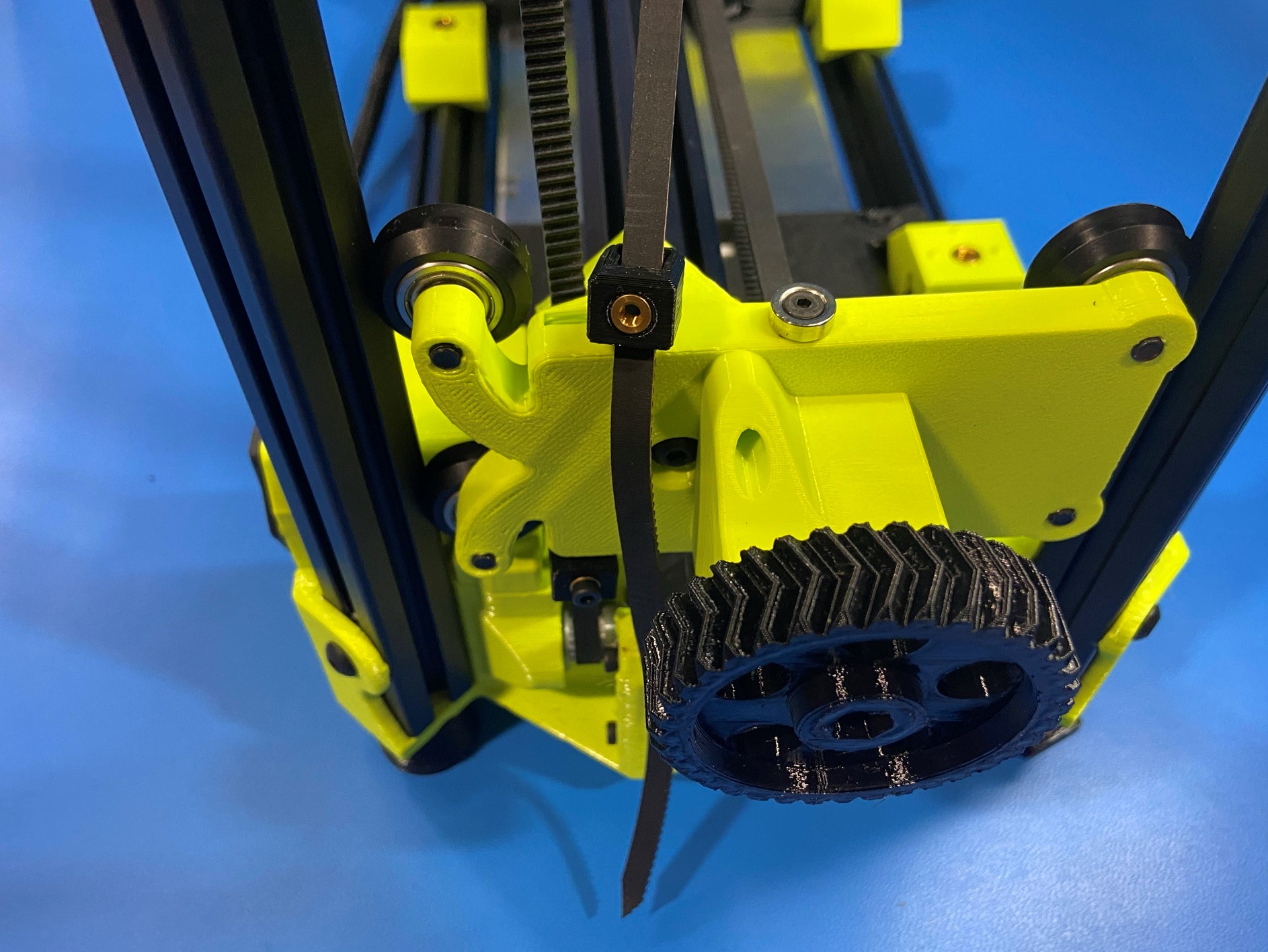
Then starting with either side, feed the belt around the timing pulley making sure there is no twist in the belt. Now pull the belt up and route it through the inner most hole on the X end and pull through.
Repeat for the other belt on the other side.
Once both belts are around the timer pulleys and through both X ends, hold the ends of both belts and push the X axis all the way down so you have room to work at the top of the printer.
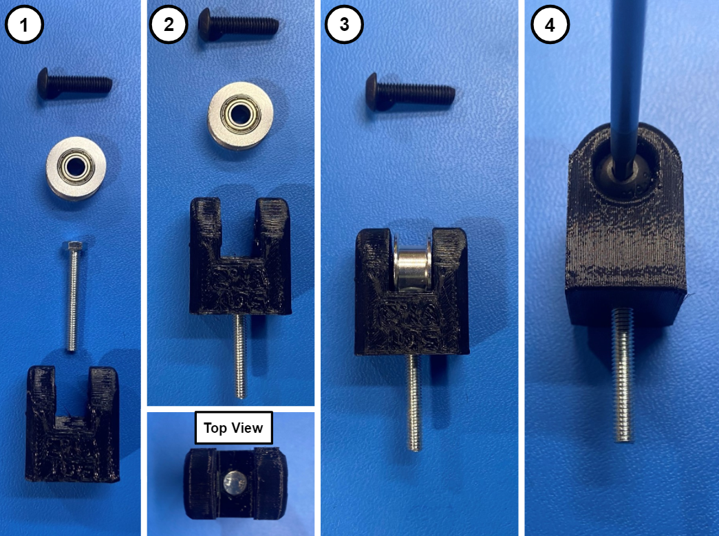
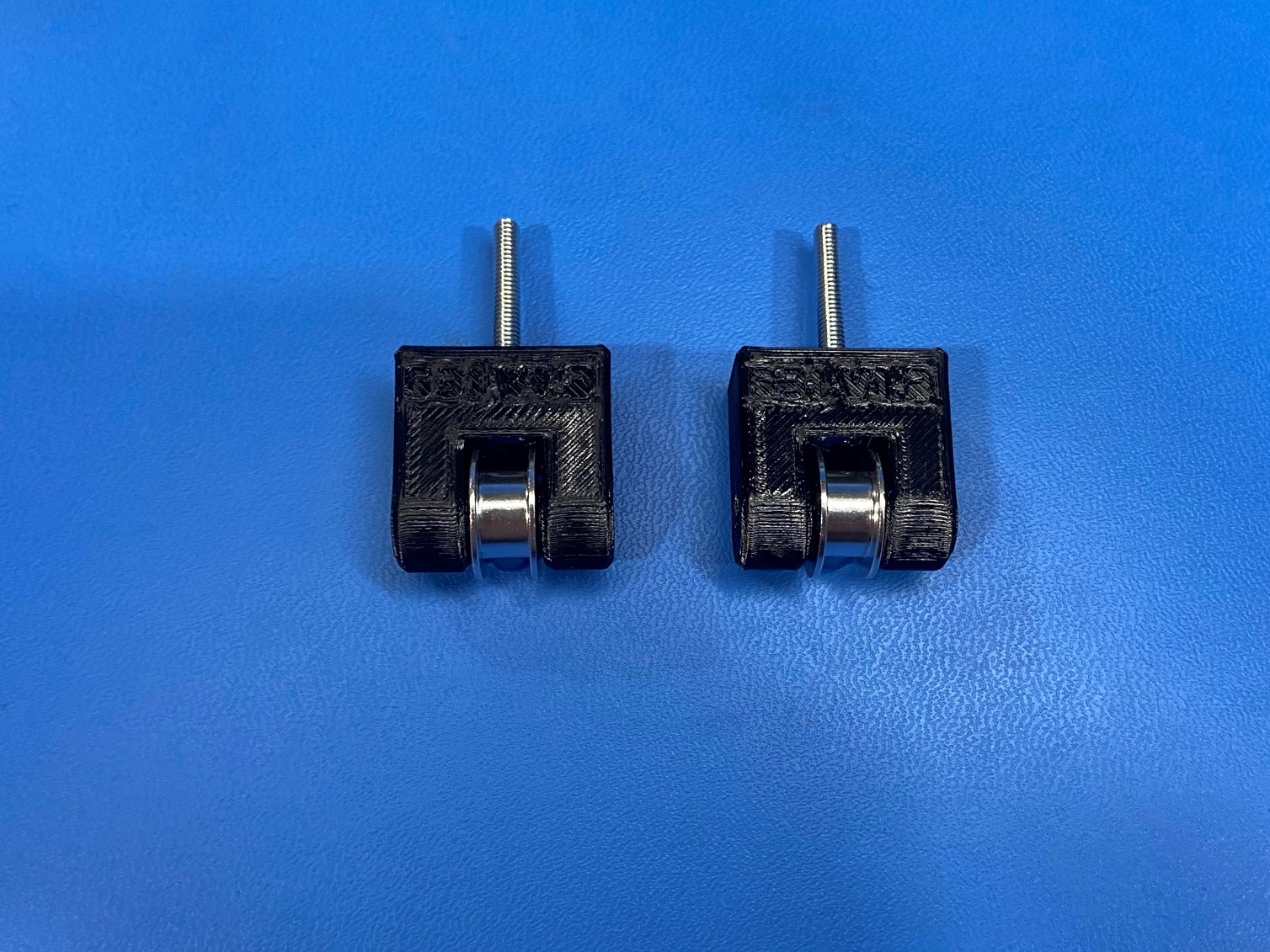
Gather the following material for the Z belt tensioner assembly: 1x Z belt tensioner [PP-GP0531], 1x 5mm smooth bore idler [HD-MS0593], 1x M4x30 HHCS [HD-BT0266] and 1x M5x20 BHCS [HD-BT0272]
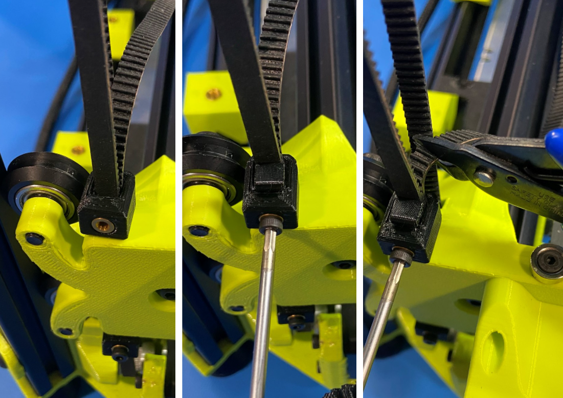
Then take the M4x30 HHCS and push it through the Z belt tensioner making sure the head of the bolt is seated inside the hex hole on the tensioner.
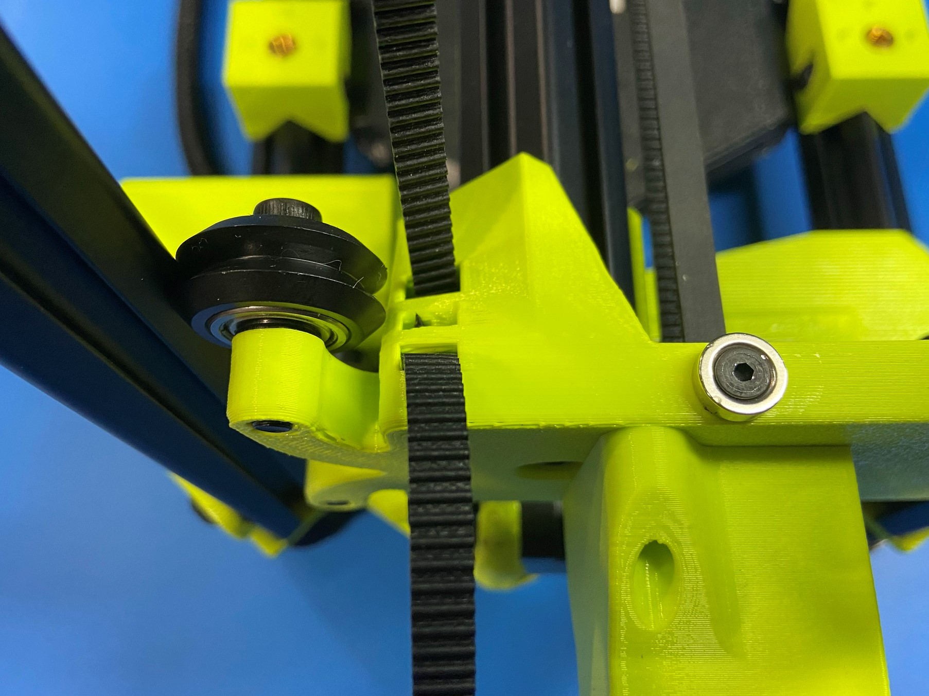
Slide the smooth idler in-between the two walls on the tensioner and secure with the M5x20 BHCS, making sure to not over tighten. We will need two Z belt tensioners so repeat process for second assembly.
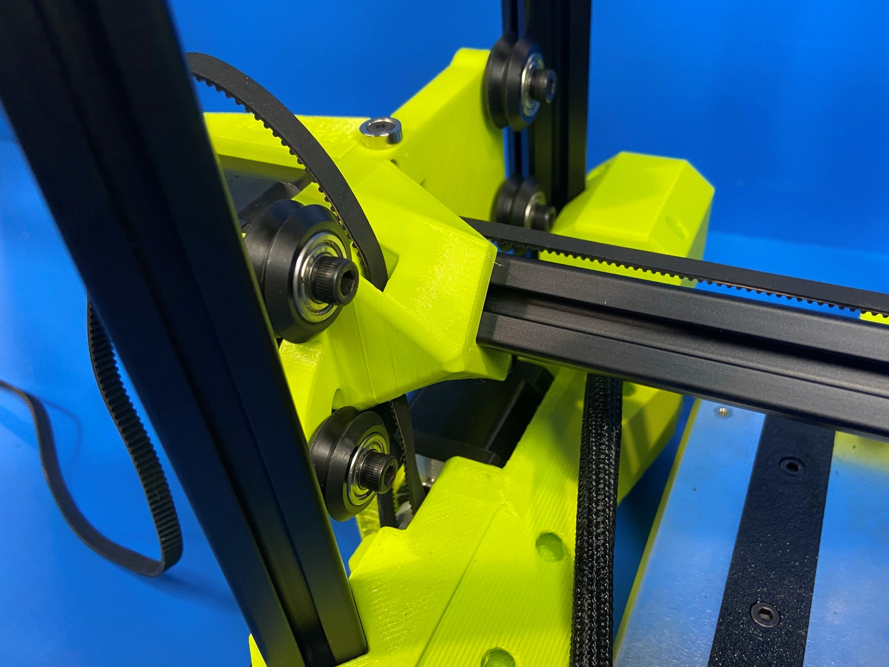
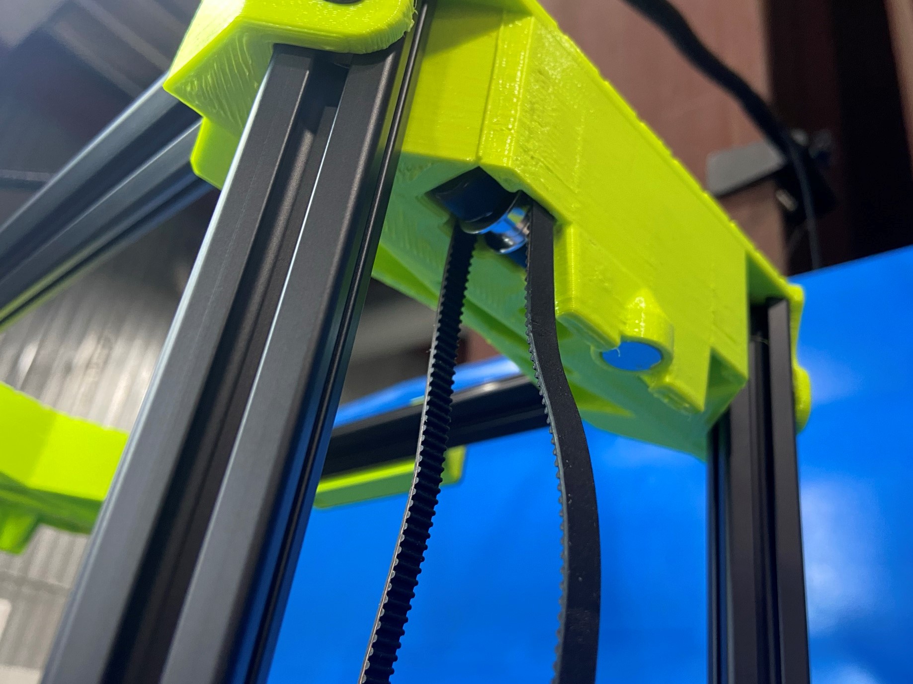
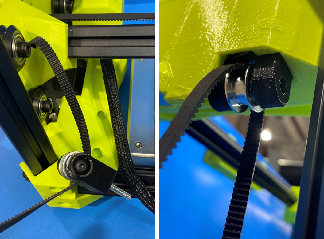
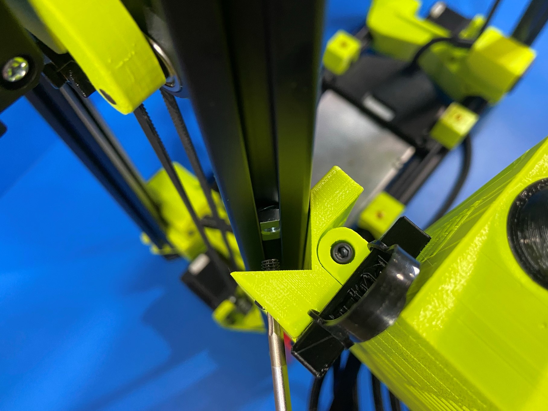
Route the belt around the smooth idler making sure the head of the bolt on the tensioner is facing the front of the printer, then push the tensioner into the channel on the underside of the Z upper. (Use the channel that is closest to the rear side of the printer.)
Then place a M5 washer [HD-WA0040] around the tail of the bolt, and screw 1x XYZ belt tensioner knob [PP-GP0557] onto the bolt until the end of the bolt is level with the top of the nut.
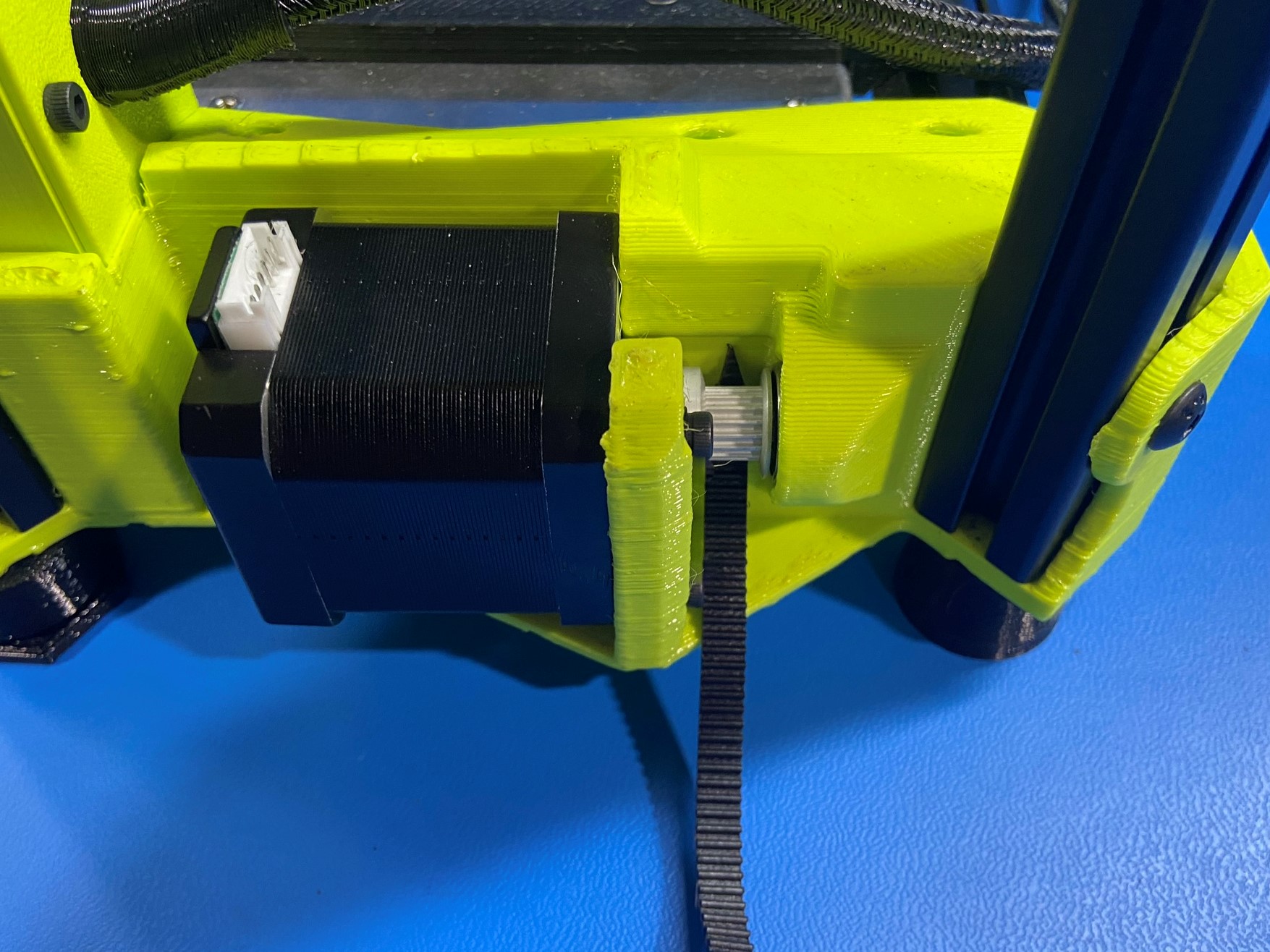
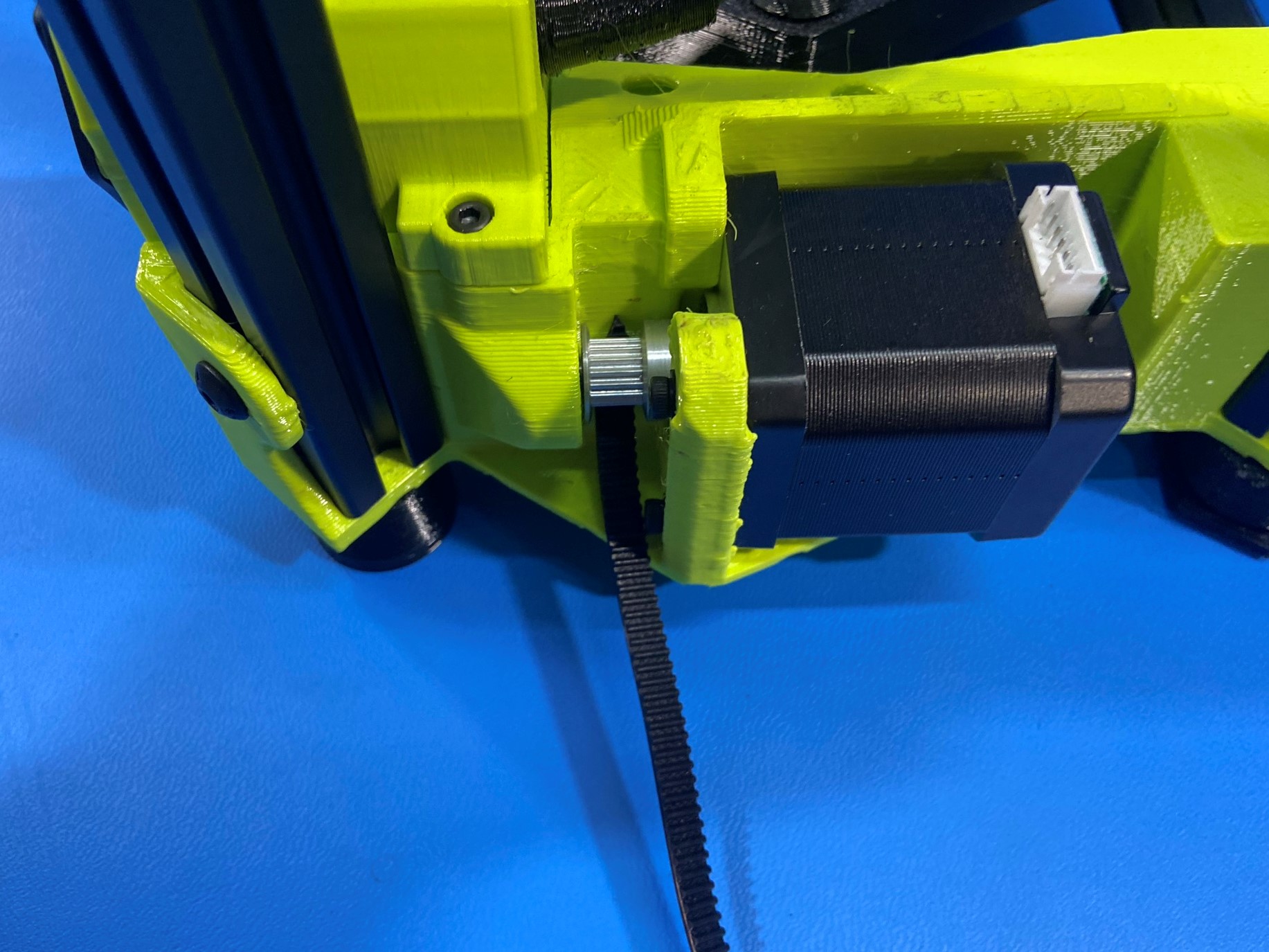
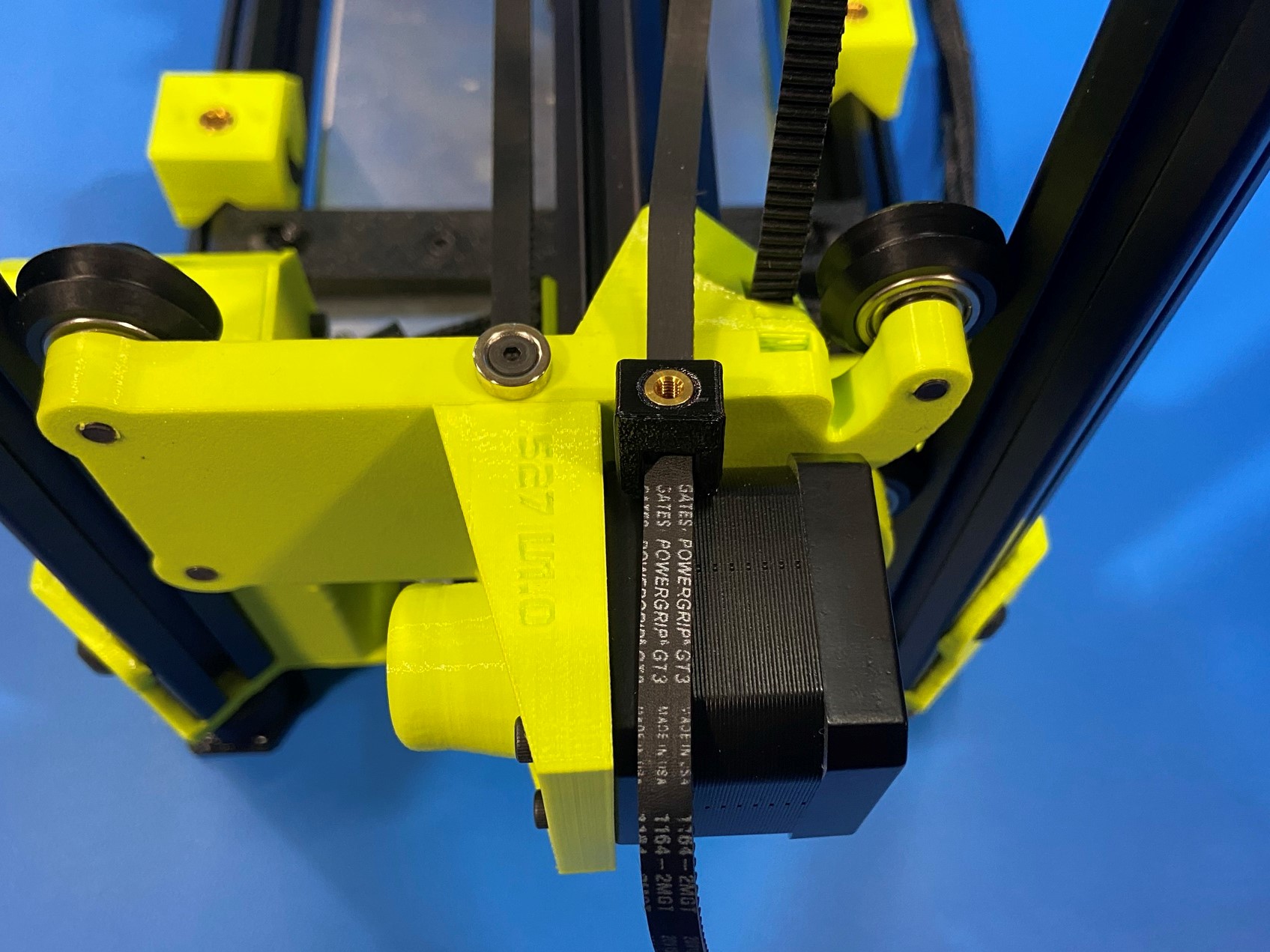
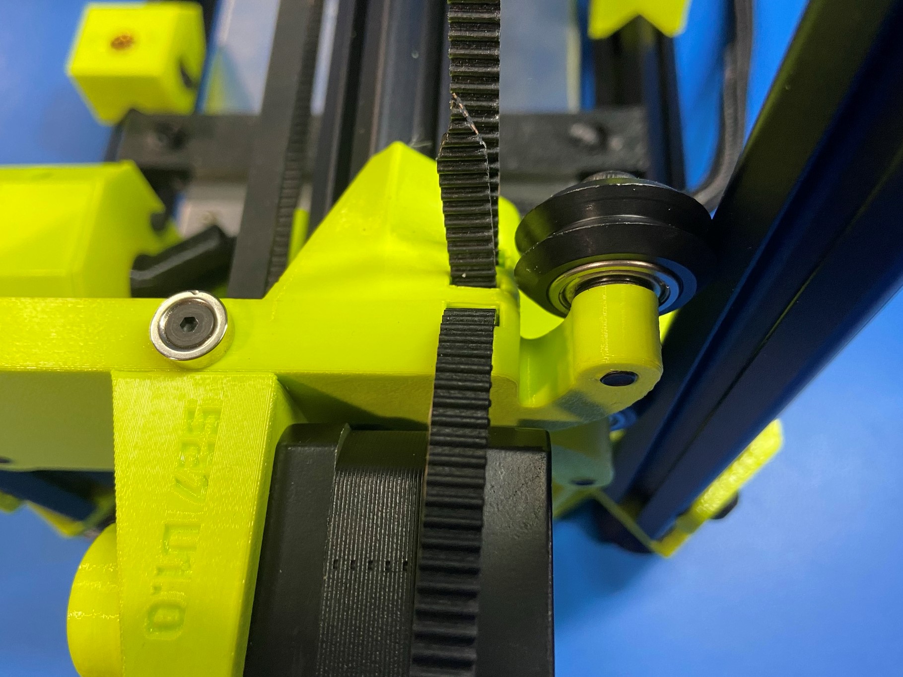
Take 1x belt clamp [PP-GP0532] and slide in around the end of the belt. Then push the end of the belt through the outside hole on the X motor so that it comes through the middle hole.
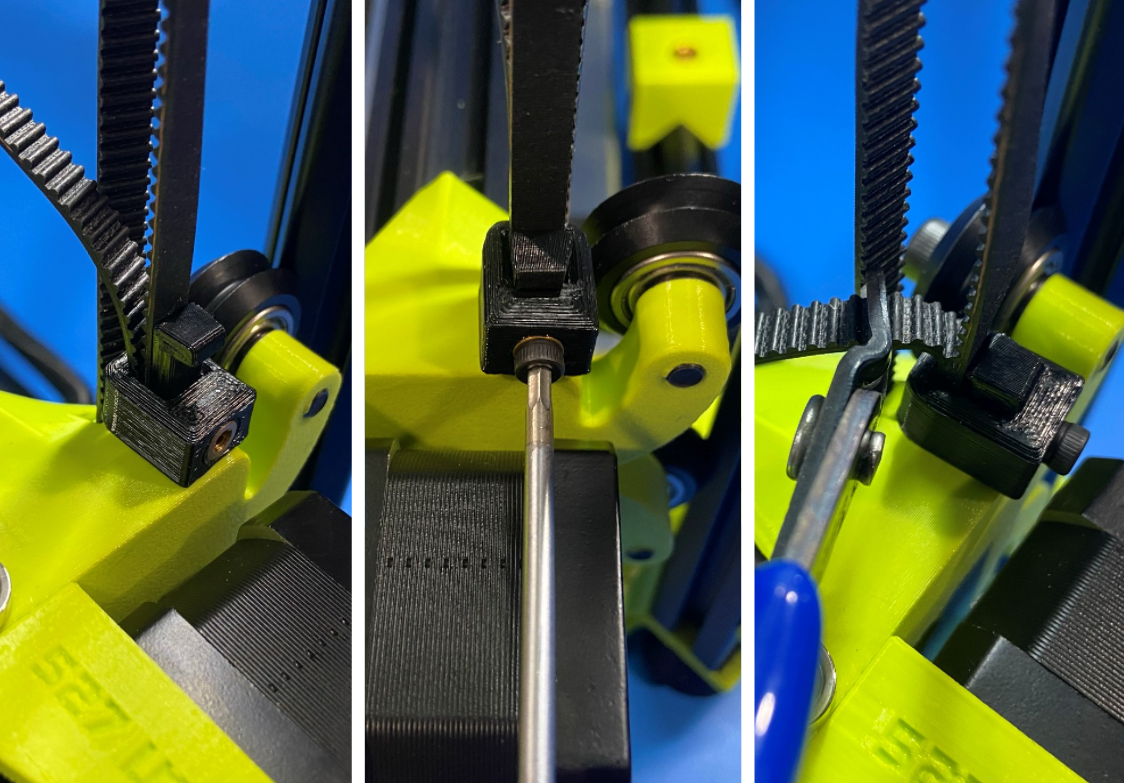
Pull on the end of the belt so that there is little slack, then take the belt clamp and slide it around the end of the belt again so it is holding the over lapping belt in place . Now take the belt clamp sled [PP-GP0649] and wedge in between the belt clamp and belt then secure with M3x8 SHCS [HD-BT0157].
Once belt clamp is secure trim belt so there is 3-5 teeth left on the end.
Repeat process for the other Z belt.


Using 2x M5x10 SHCS [HD-BT0073] mount the LCD backplate assembly to the front right extrusion.
You will need to align the top hole on the LCD mount with the top M5 post assembly T-slot nut [HD-NT0044] and loosely fasten the M5x10 SHCS. Followed by aligning the bottom hole with the bottom T-slot nut.
Then slide the LCD mount up aligning the top edge with the bump stop located on the bottom side of the Z upper. Tighten both bolts to secure the LCD mount to the extrusion.
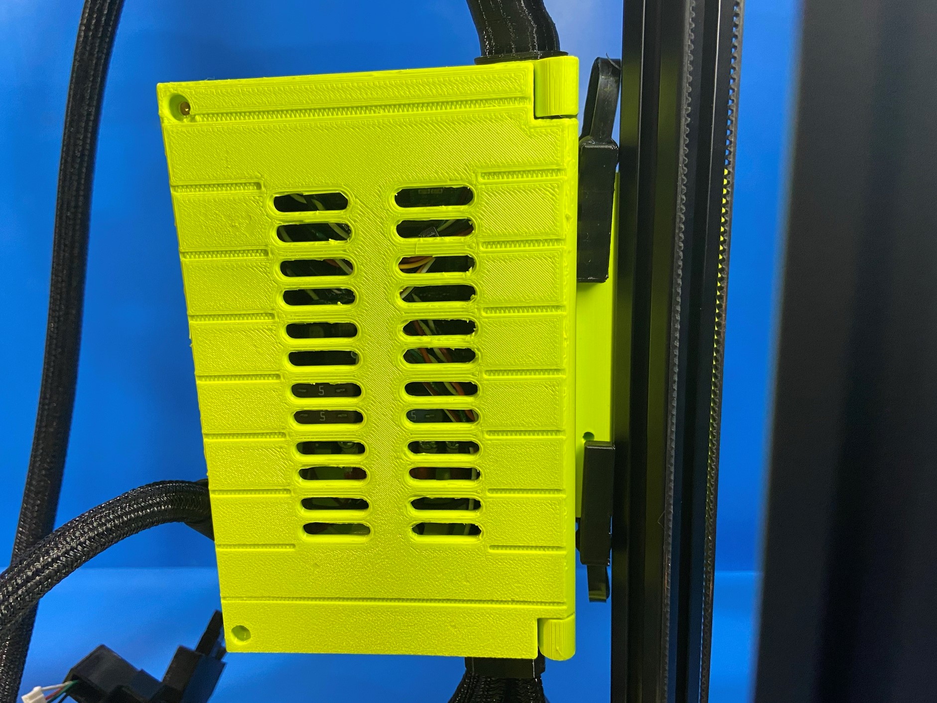
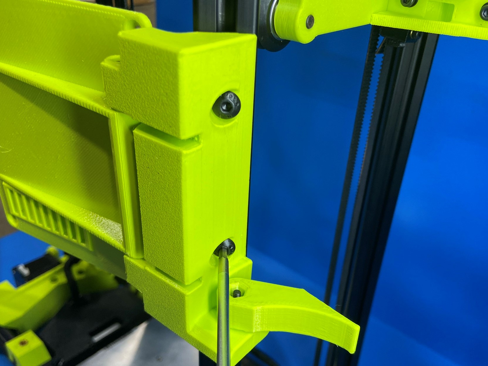
Using a similar process attach the control box assembly to the extrusion right behind the front right extrusion.
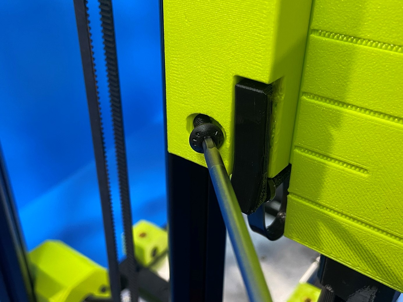
Start by aligning the top hole on the control box mount with the top T-slot nut, then loosely fasten 1x M5x10 BHCS [HD-BT0073] to the T-slot nut.
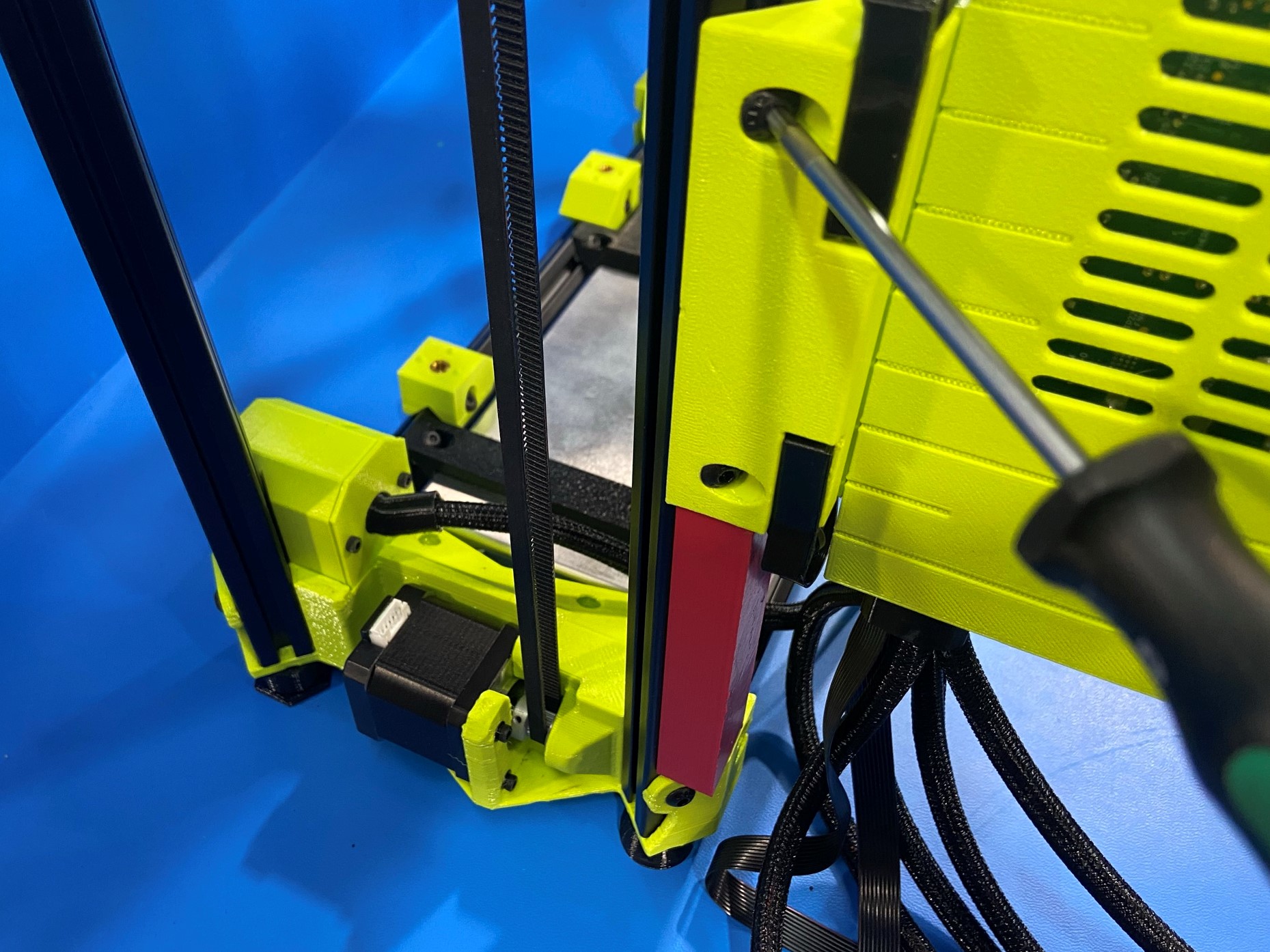
Repeat with the bottom hole and bottom T-slot nut, then place control box spacing jig under the control box mount then tighten both bolts.
Once the control box mount is secured to the extrusion remove the spacing jig and both CB clips. Rotate the control box so that it is parallel to the X axis then replace the CB clips.


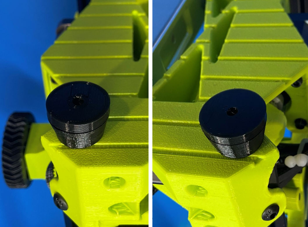
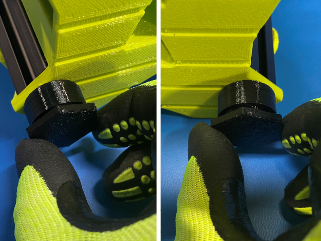
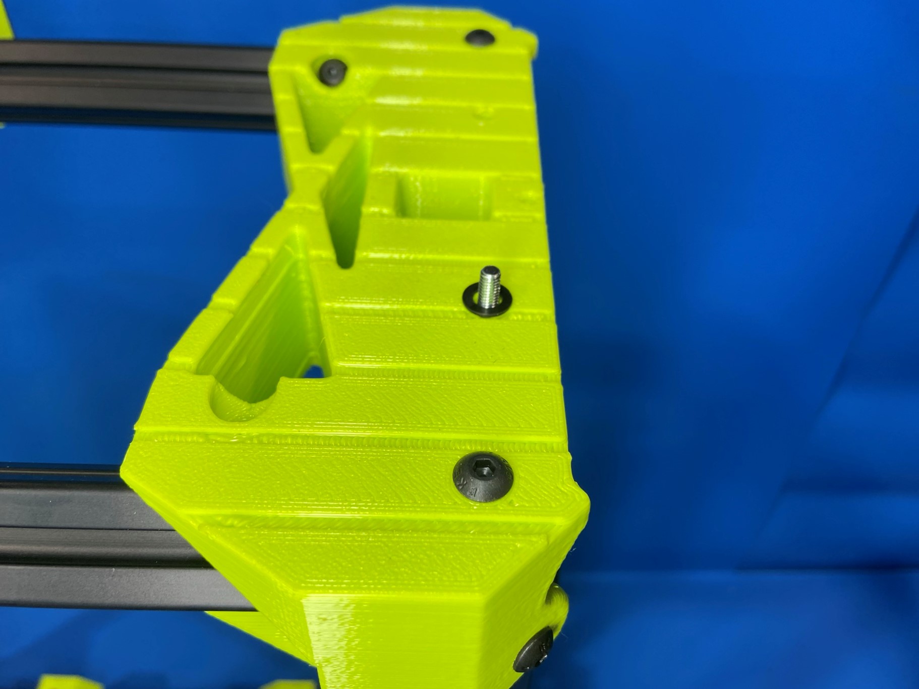
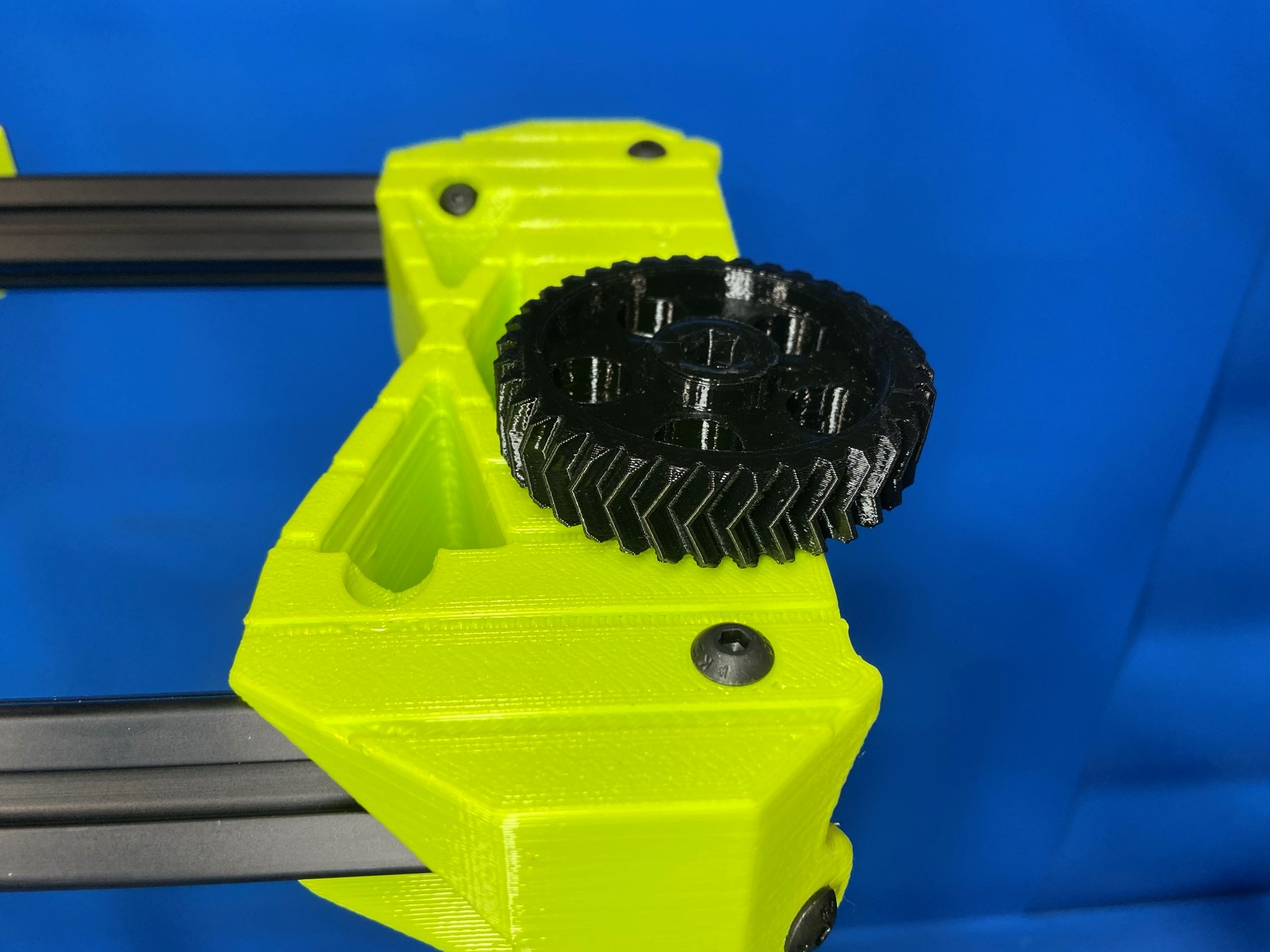
Using 1x M5 28mm DIA press fit knob [PP-GP0587] secure the feed tube holder mount [PP-GP0594] to the front left extrusion. Rotate the feed tube mount so it is in the vertical position then slide it to the top of the extrusion.
Repeat process for the spool arm assembly using 1x M5 28mm DIA press fit knob. Then rotate spool arm to the vertical position and slide it up on the extrusion leaving a small gap between the spool arm and feed tube mount.
Take all the wires from the control box and place them all inside the printer to make sure they are not damaged when the printer is moved.