Open HardwareAssembly Instructions
Guides for installation and assembly of the LulzBot line of products made by FAME 3D LLC.
Guides for installation and assembly of the LulzBot line of products made by FAME 3D LLC.
Components:
Printed
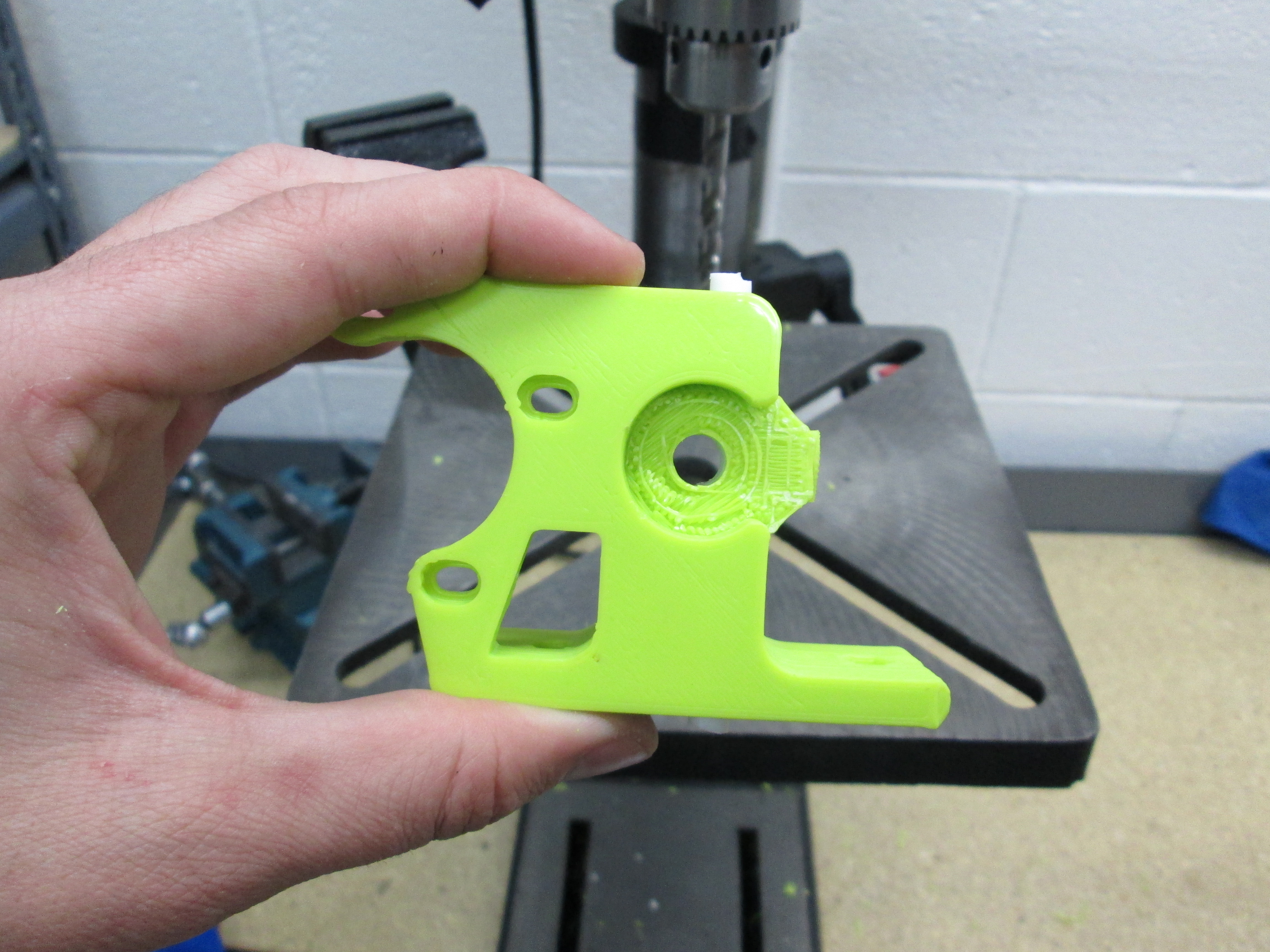
1 - Flexystruder Body
1 - Large Herringbone Gear
1 - Small Herringbone Gear
1 - Extruder mount, TAZ
1 - Extruder Washer
Hardware
1 - M3 Nut
1 - M3 Set Screw (Grub Screw)
4 - M3-.5 3.8mm Heatset Insert
3 - M3 x 5 Bolt, SHCS Black-Oxide
3 - M3 Washer, Steel, Zinc Plated
2 - M4 x 20 Bolt, SHCS Black-Oxide
2 - M4 Washer
2 - M4 Nut,Zinc-Plated Steel
1 - Hobbed, M8 x 60 Hex Head Bolt
1 - M8 Nyloc Nut, Zinc Plated
4 - M8 Washer, Steel, Zinc Plated
2 - 608ZZ bearing
1 - M5-.8 11mm Heatset Insert
1 - M5 x 20 Bolt
1 - Thumb Screw Knob for M5 SHCS, Black
75mm - .25”ODx.125”ID PTFE tube (~2.5”)
Electrical
1 - Assy, Budaschnozzle 2.0c with 0.5 nozzle
1 - NEMA 17 Stepper Motors, wires cut to 60mm
4 - Connector Pins, Male
1 - Connector, 4 pin Male housing with latch
50mm - EMI/RFI-Shield Heat-Shrink Tubing 3/16" ID Before, 3/32" ID After, 48" L, Black
Tools:
13mm Wrench
2.5mm Allen Driver
1.5mm Allen Driver
3.5mm drillbit
6.5mm drillbit
8mm drillbit
Box cutter


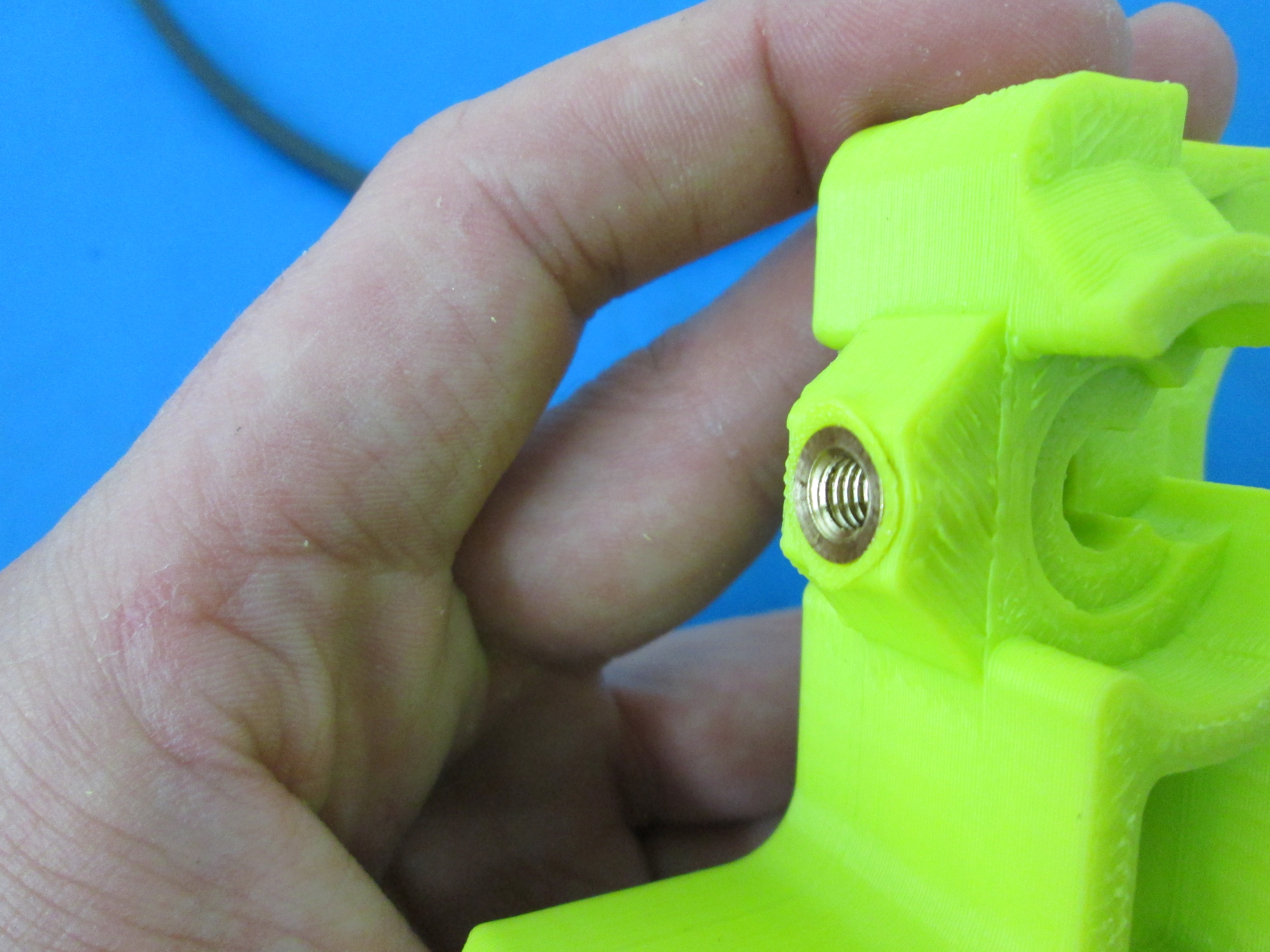
Using a soldering iron, insert 4 M3 heatset inserts into the sides of the extruder mount and one M5 heatset insert into the side of the flexystruder body. Make sure that the tops of the inserts are flush with the surface of the part.


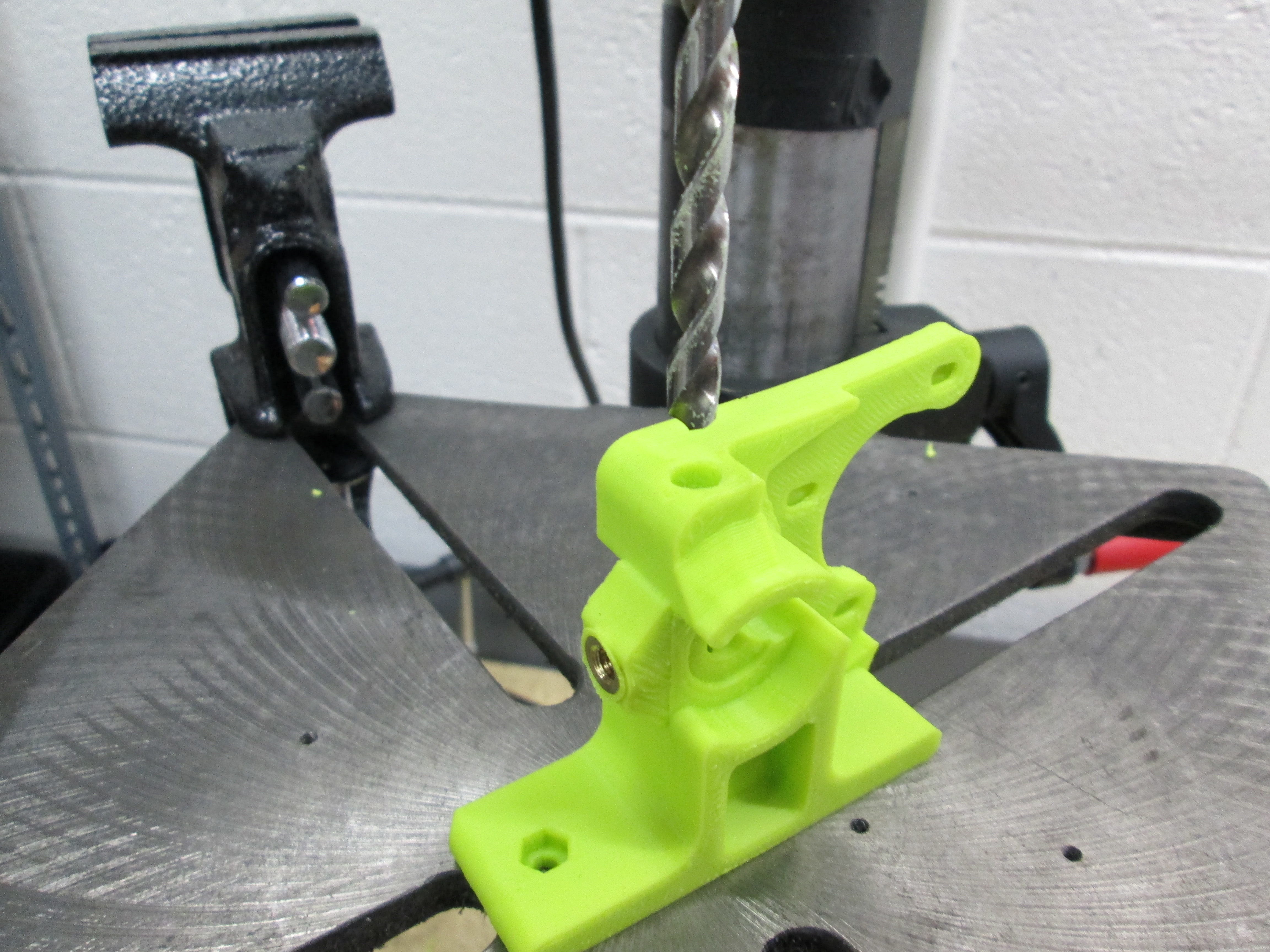
Using a 6.5mm drillbit, drill through the entire length of the flextstruder from the top down. The existing hole should guide the drillbit through.
Cut a piece of the PTFE tube to 2.5", or just longer than the length of the Flexystruder Body. Slide this piece onto the 2.5mm allen wrench, and then press into the flexystruder body so that a small amount is sticking out from the top and bottom.
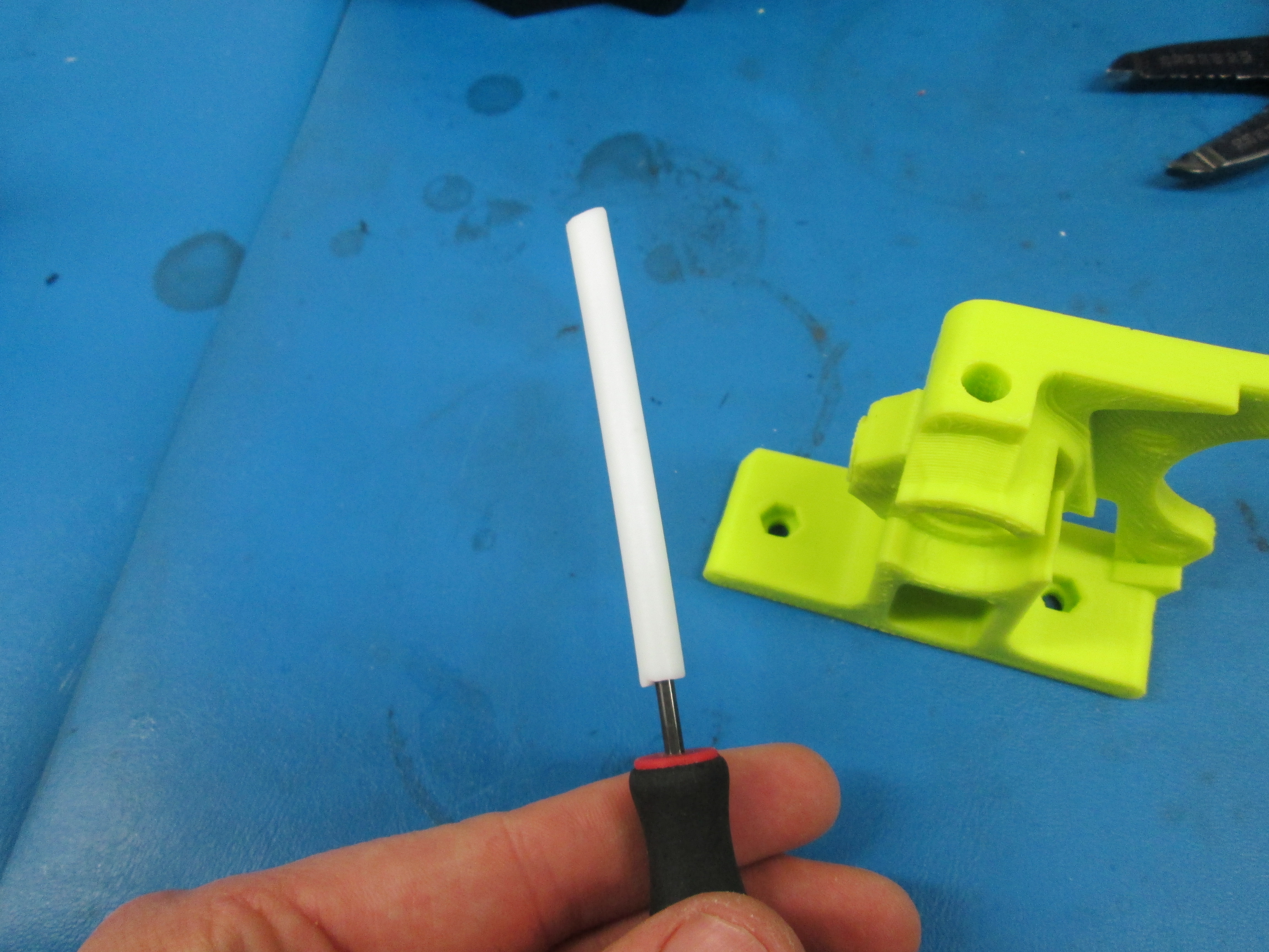

Drill out the entire length of the PTFE tube with a 3.5mm drillbit. This should clear out the drilled section of the PTFE tube.
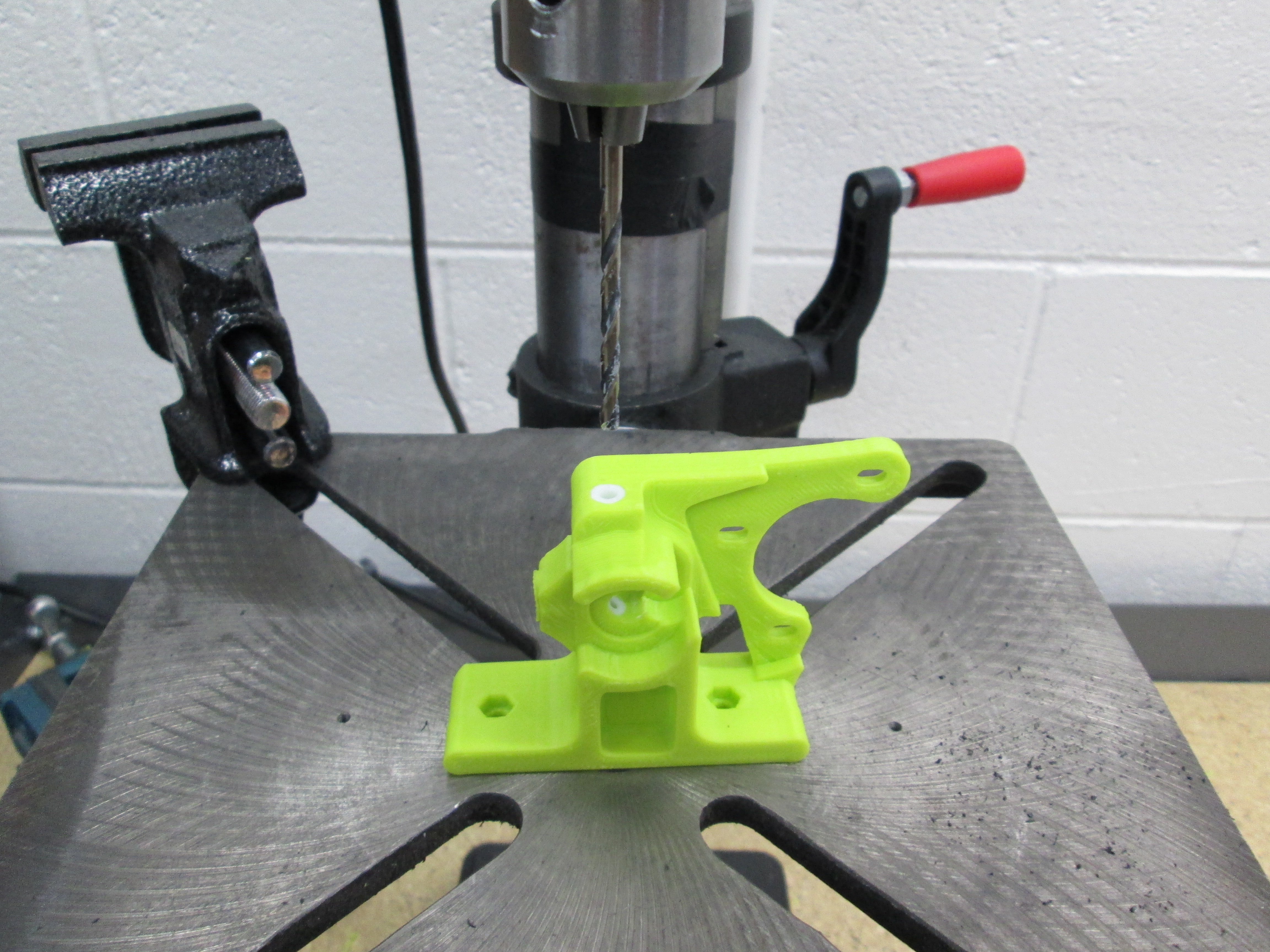

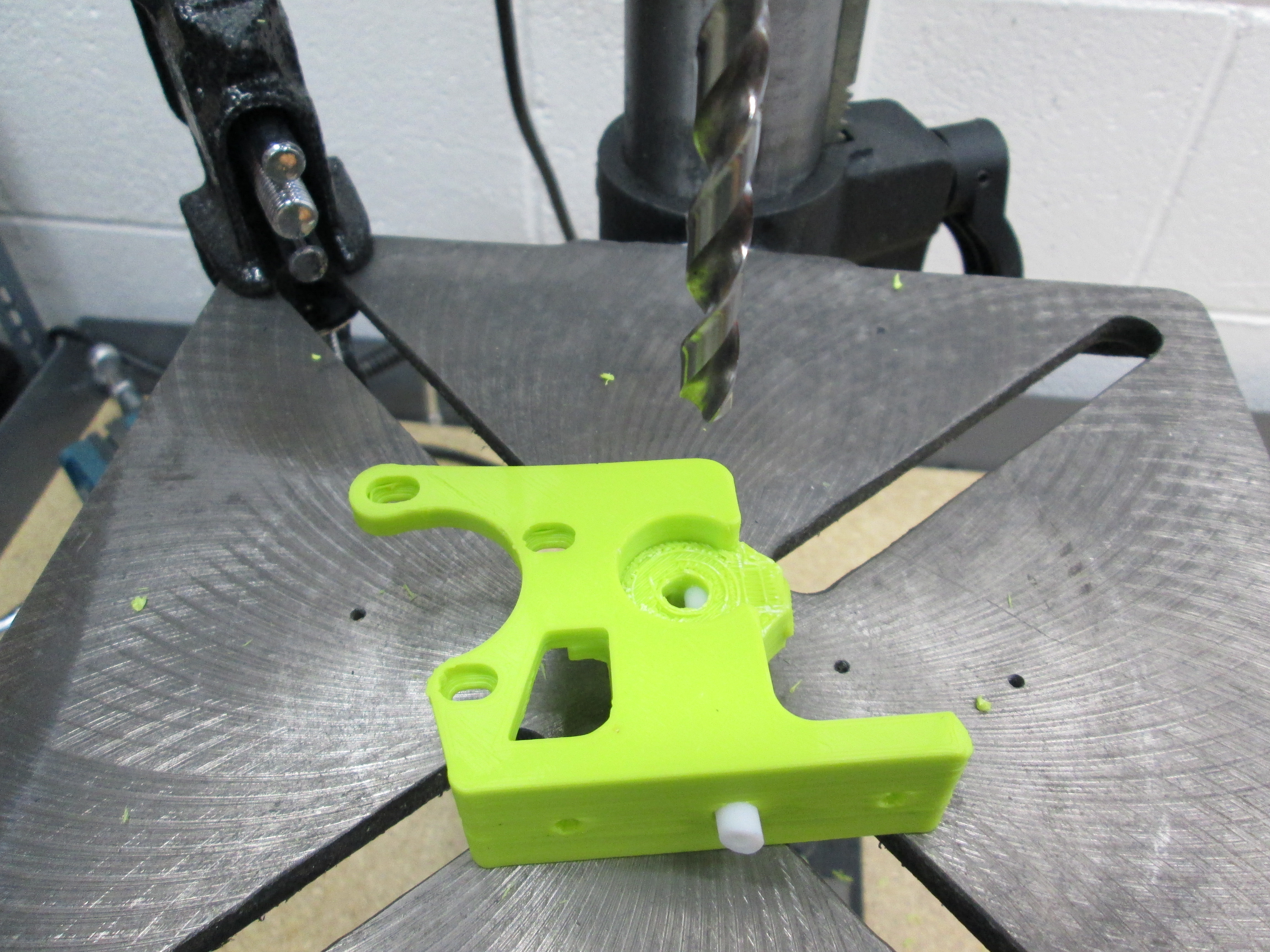
Using an 8mm drill bit, drill through the PTFE tube using the bolt hole through the flexystruder body as a guide
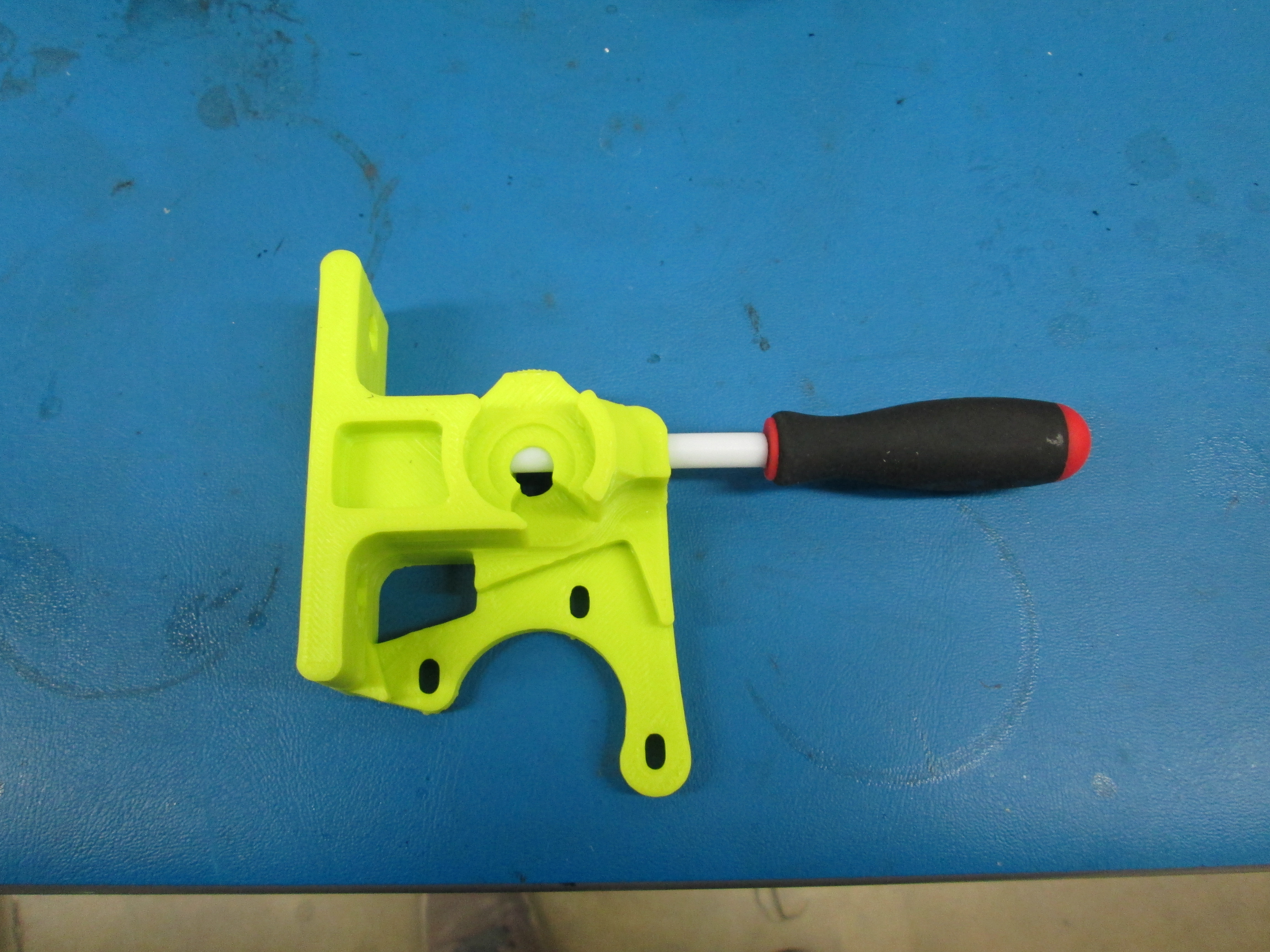
Using a box cutter, trim the ends of the ptfe tube flush with the end of the flexystruder body
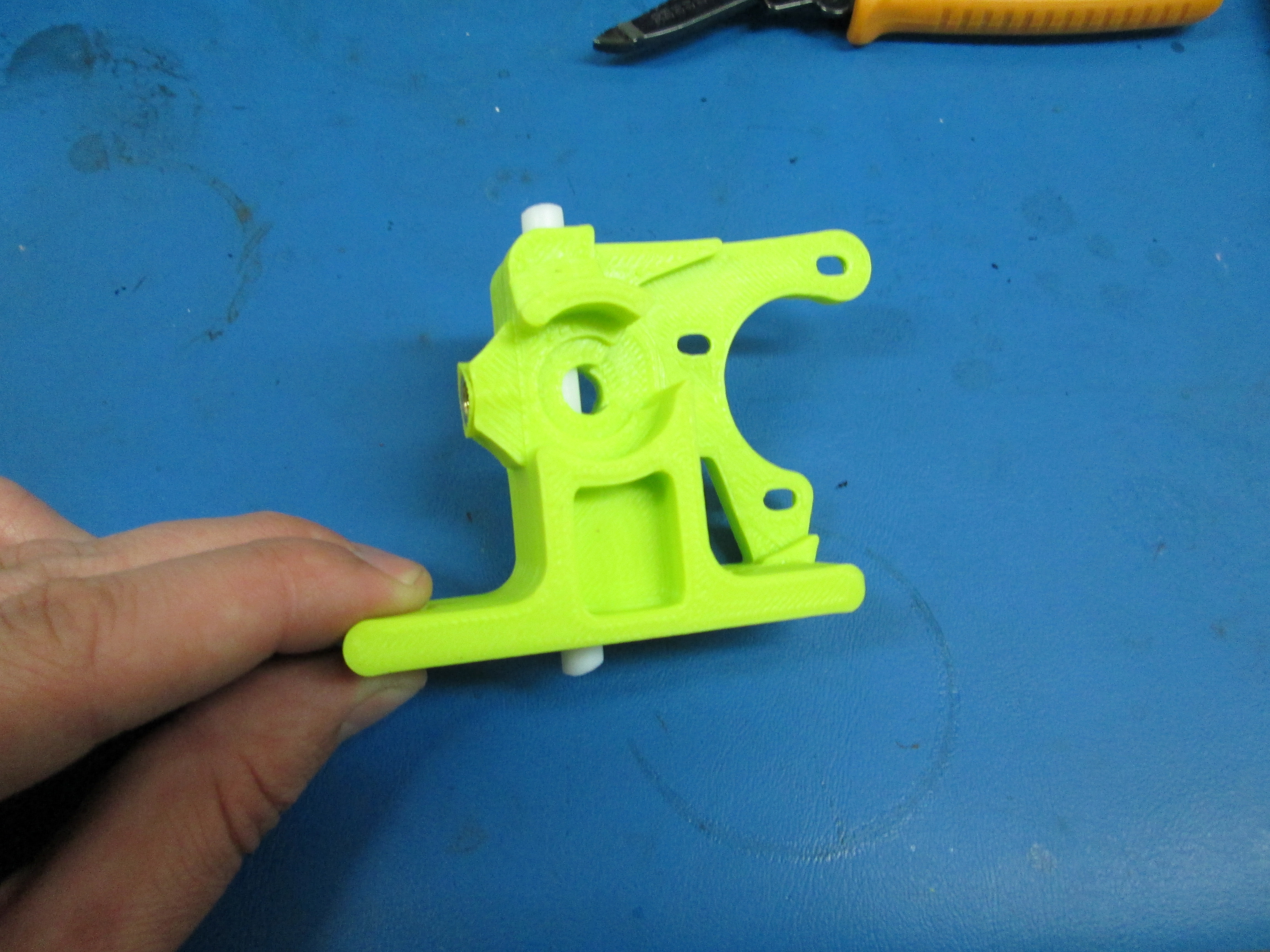

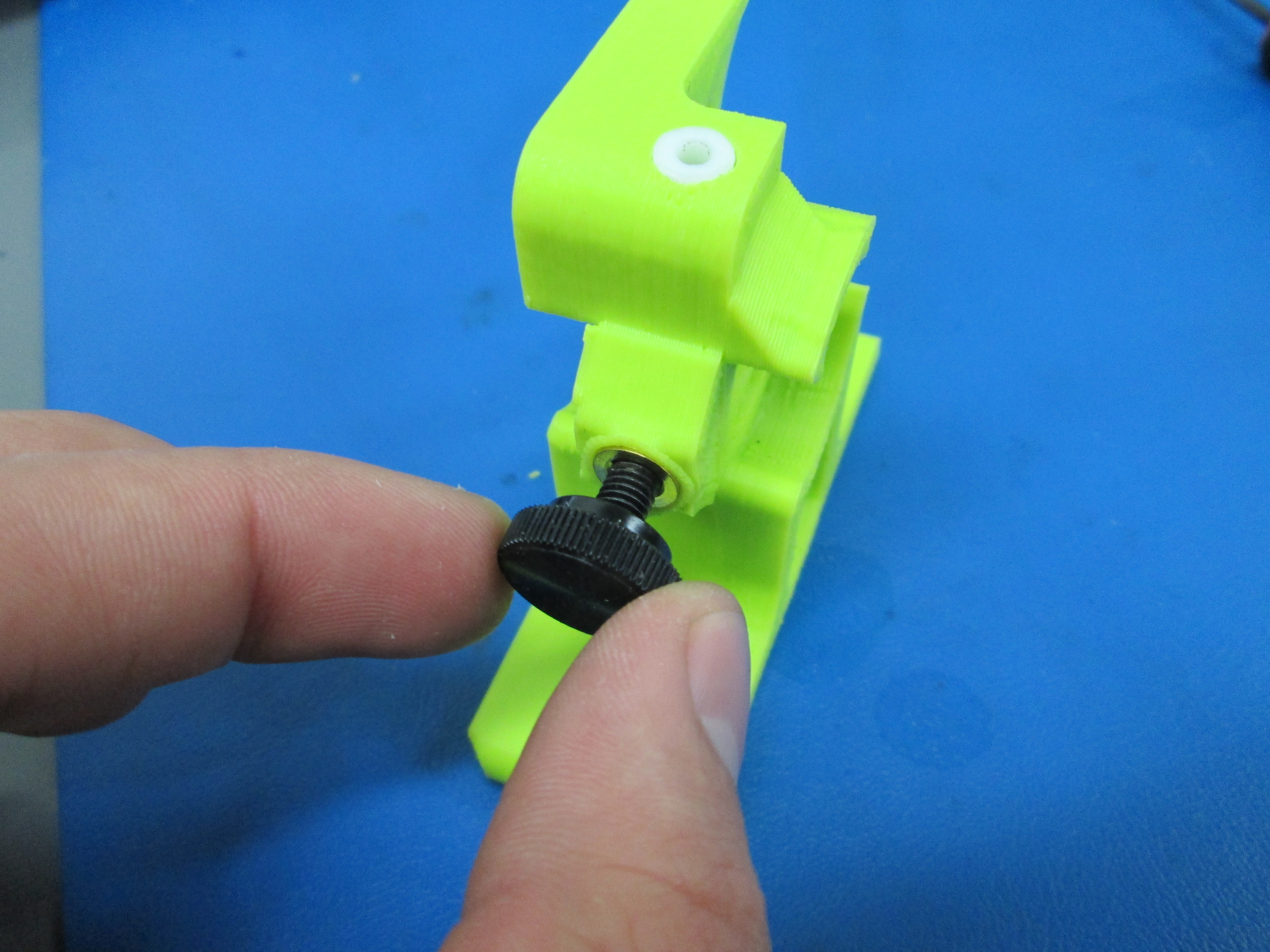
Screw in the M5 x 20 with thumb screw cap into the M5 insert in the side of the extruder. It only needs to be finger tight.
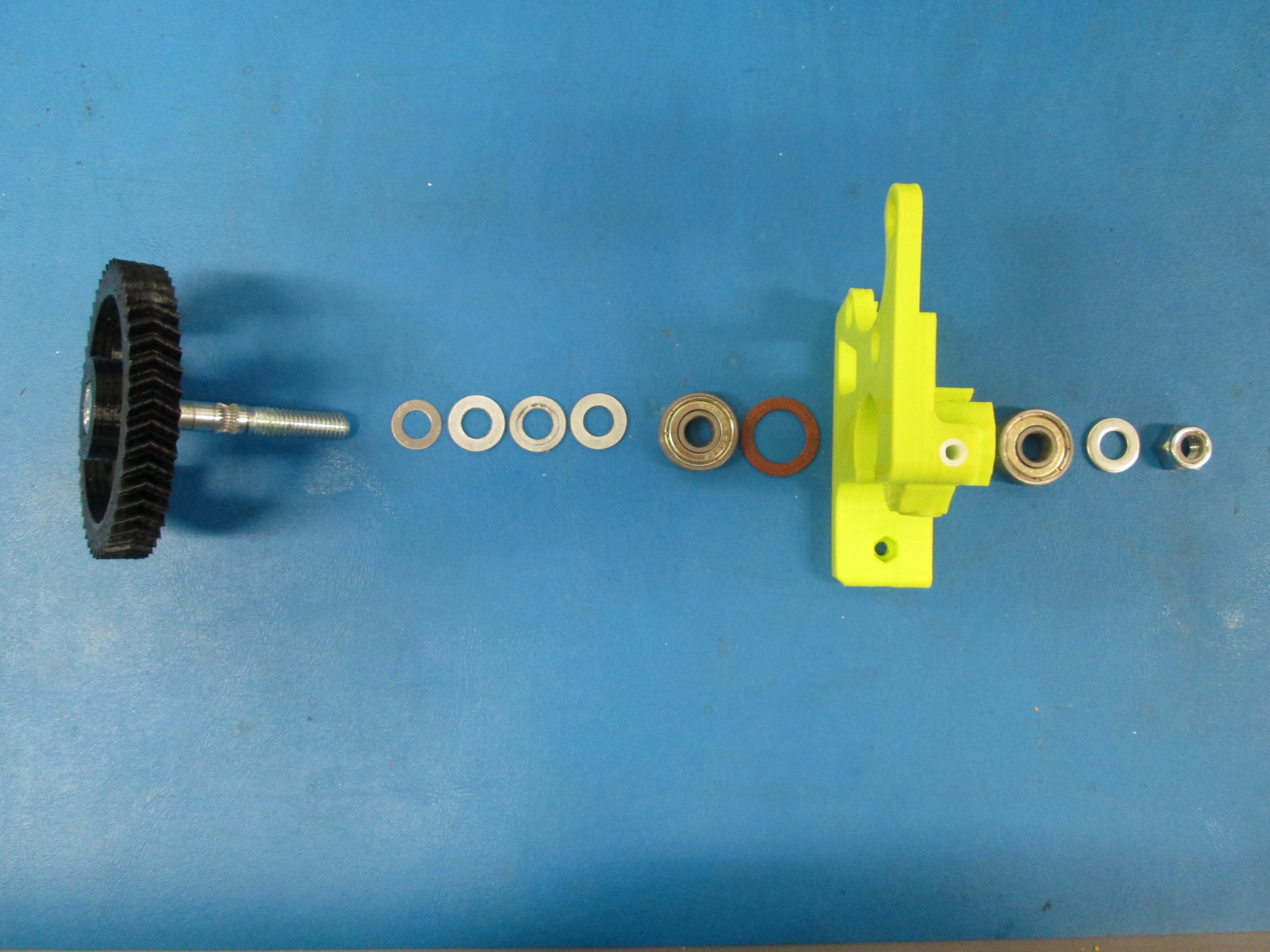
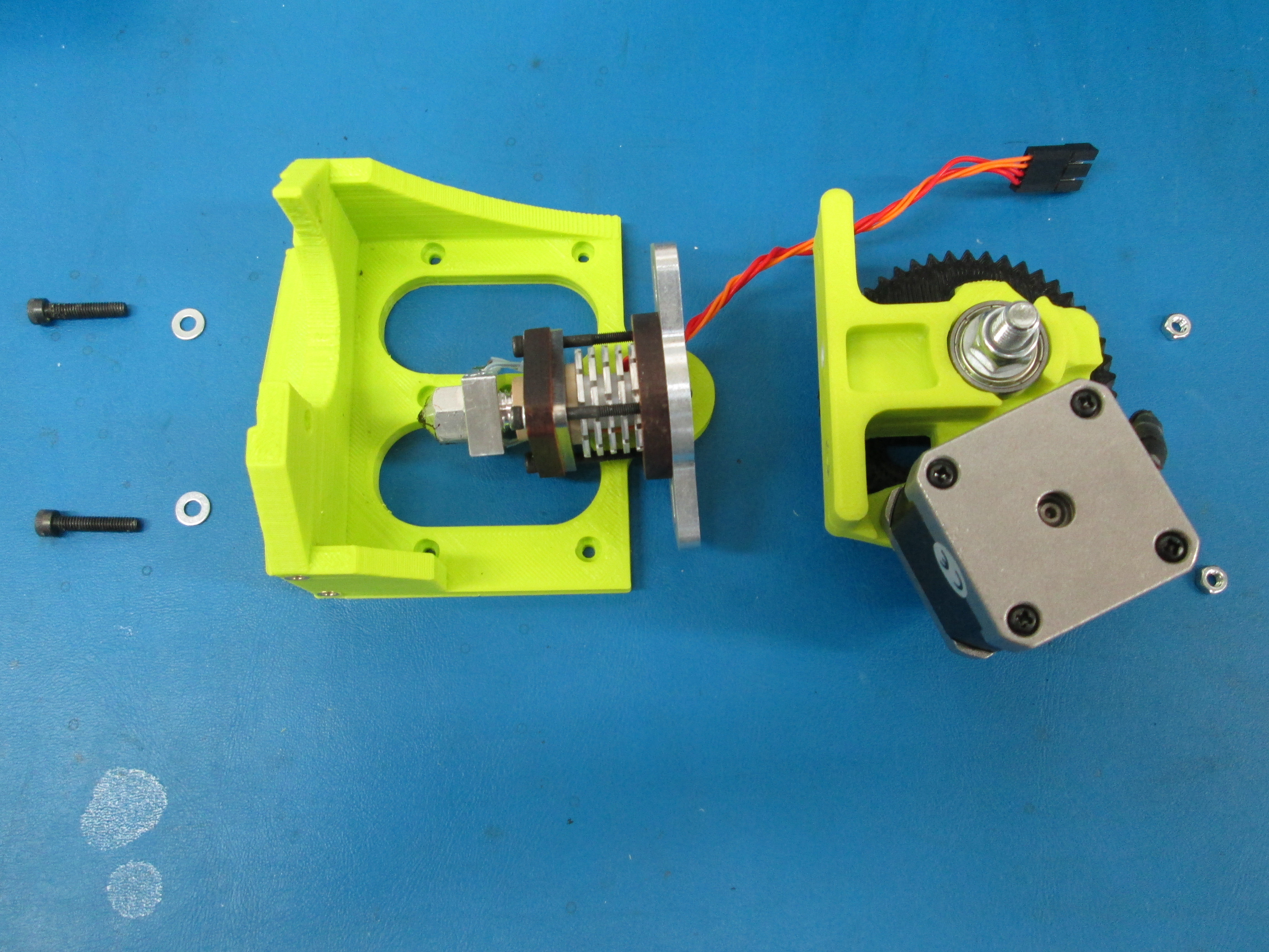
Press the M8 hobbed bolt into the larger gear, then stack 4 M8 washers, 1 608ZZ bearing and the printed washer on the hobbed bolt. Press it in to the front of the extruder body (the one that printed flat on the glass).
Check to make sure that the teeth of the hobbed gear line up with the hole in the PTFE tube, if it doesn't you may need to remove washers and/or add shims
On the other side, stack a single 608zz bearing, a sacher and the M8 nylock nut. Tighten until the gear no longer wobbles at all, but spins freeley.
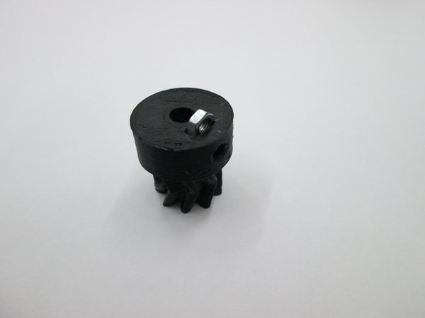
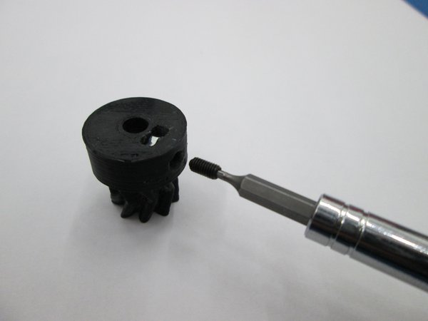
Install the M3 nut into the bottom of the small herringbone gear.
Then install the M3 x 6mm set screw through the side of the small gear and into the nut.
Be sure the M3 x 6mm set screw does not protrude into the hole through the small gear.
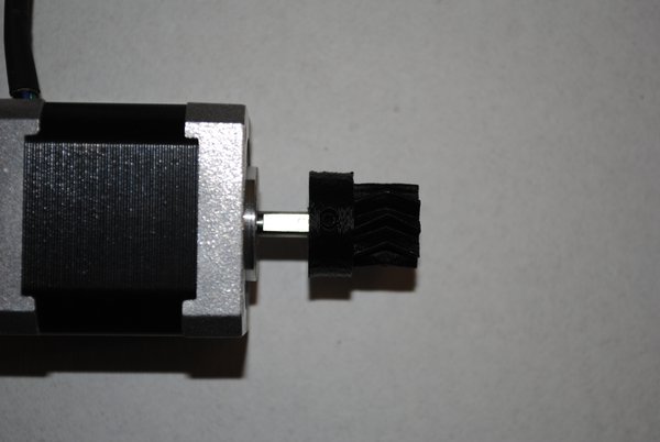
Locate the flat side of the motor shaft.
With the set screw aligned with the flat, slide the small gear onto the motor shaft.
The location will be adjusted later so positioning isn't important at this point.
Do not tighten the set screw yet.
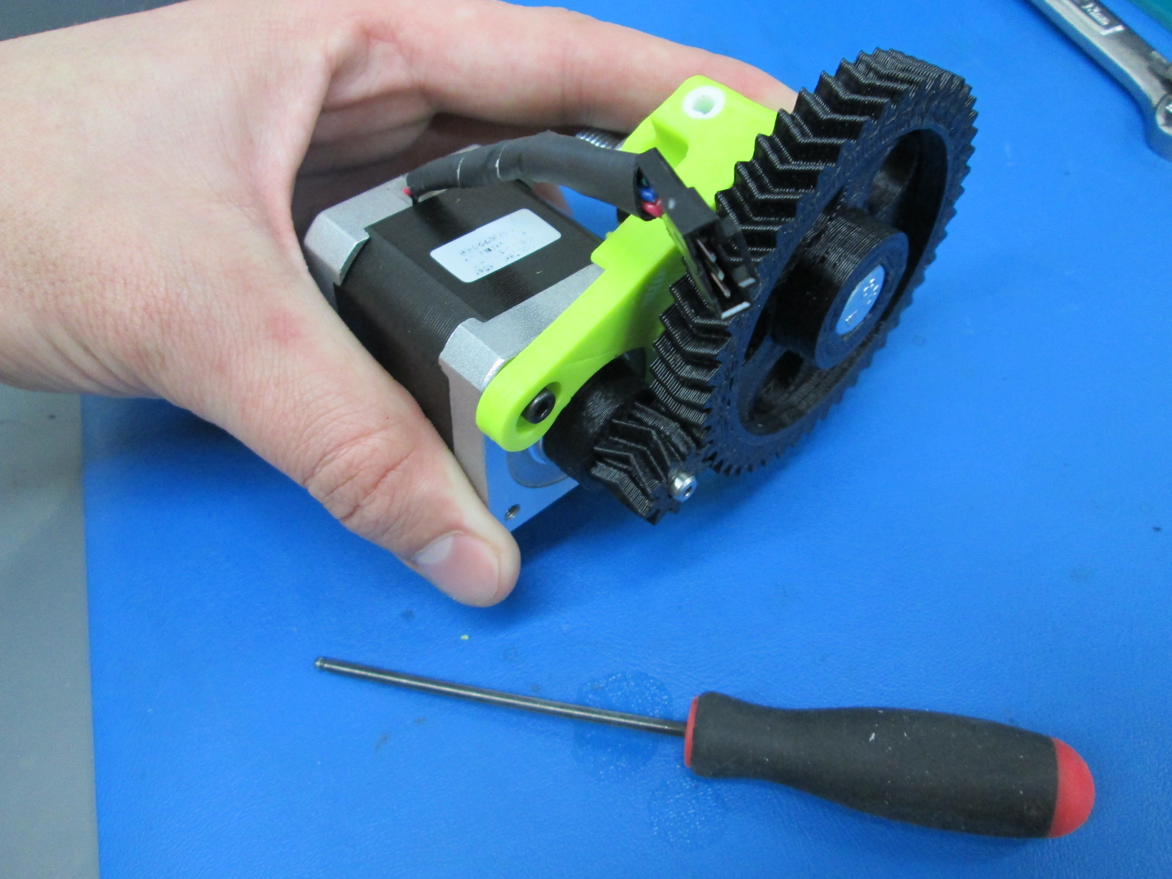
Holding the motor in the location where it will be mounted, align the herringbone gears by sliding the small gear in or out on the motor shaft so the V-grooves are centered on each other.
Install motor using 3x M3 x mm SHCS and 3x M3 washers, taking note of the orientation of the motor wires.
Push the gears together while you tighten the bolts to make sure the contact is tight.
Tighten the set screw on the small herring bone gear.
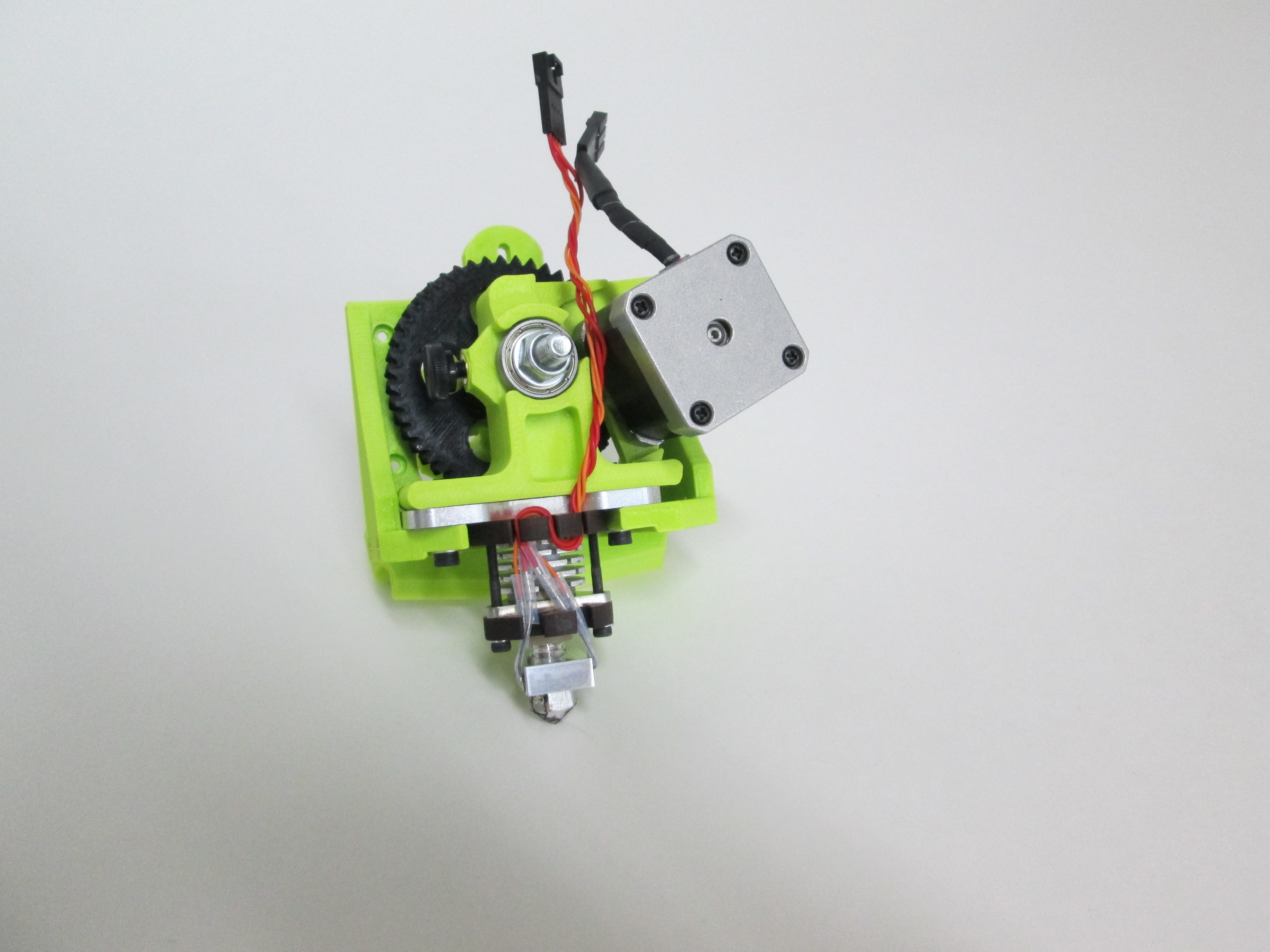
Using 2 M4 x 20 screws, 4x M4 washers and 2x M4 nuts, secure the Flexystruder body and Budashnozzle to the extruder mount as shown. Use a small piece of ABS filament to make sure that the budashnozzle and flexystruder line up. Remove this filament after bolts are tightened.

Review your work. Looks nice, doesn't it?