Open HardwareAssembly Instructions
Guides for installation and assembly of the LulzBot line of products made by FAME 3D LLC.
Guides for installation and assembly of the LulzBot line of products made by FAME 3D LLC.
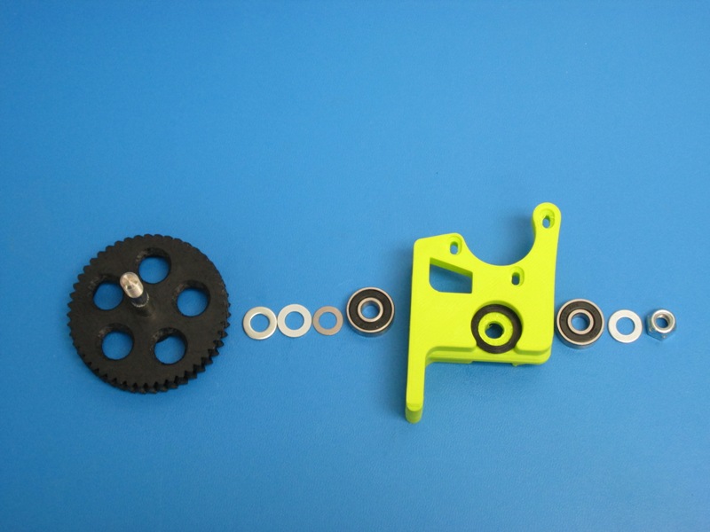
Components:
1x- Extruder Body
1x- Large Herringbone Gear with Hobbed Bolt
60mm- PTFE tubing 6.5mm OD, 3.0mm ID
1x- 608 Bearing
1x- M3 x 6 set screw
1x- M8 Nyloc Nut
1x- M8 Washer
1x- M8 Shim Washer 0.5mm, as needed
1x- M8 Shim Washer 1..0mm, as needed
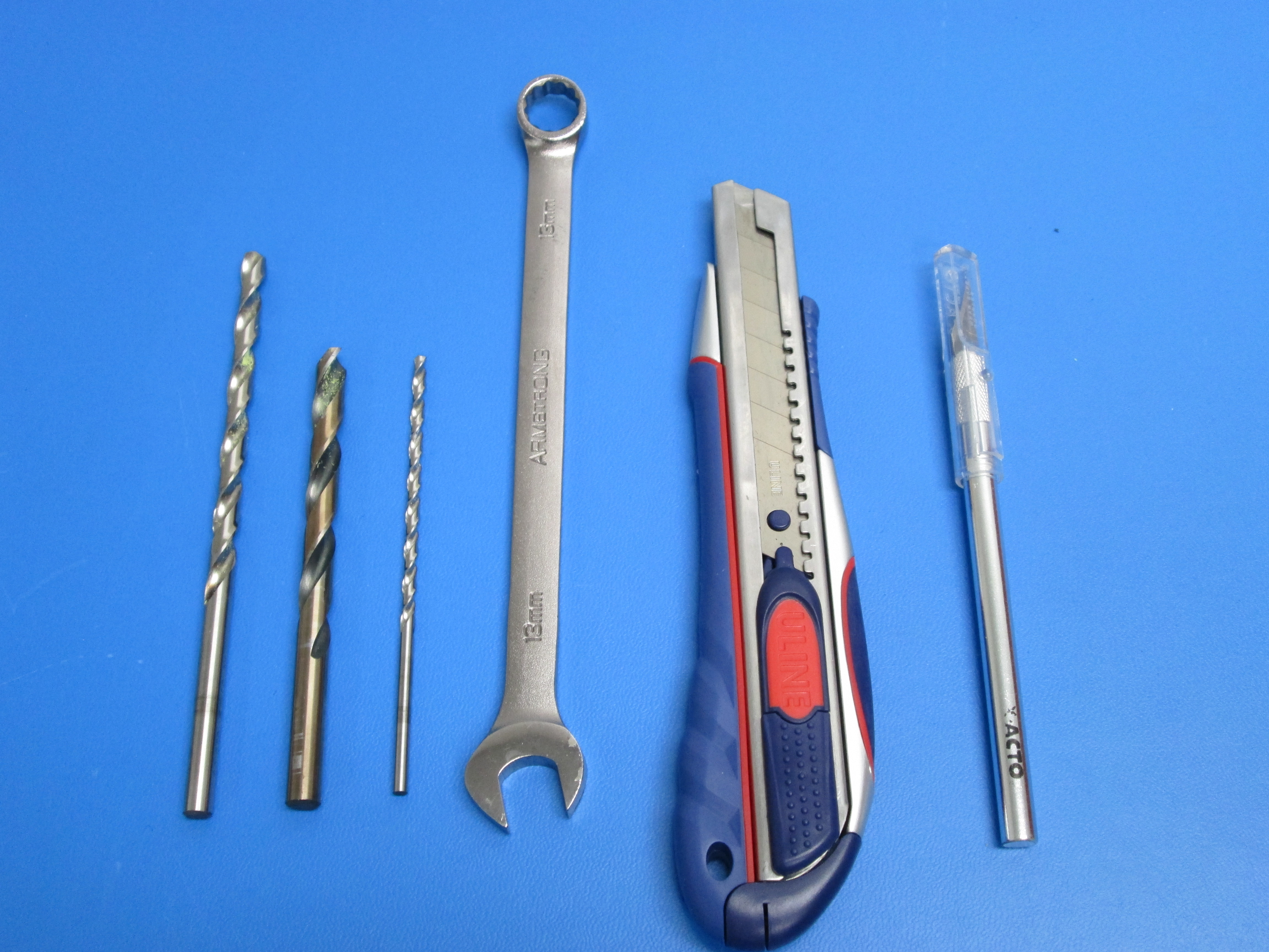
Tools:
13 mm Wrench
Precision craft knife (ex. Xacto style)
3.5mm drill bit, at least 75mm long
6.5mm drill bit, at least 75mm long- increase bit diameter to address variances in PTFE outer diameter, PTFE must still be a press fit into the part
Electric drill, preferably a drill press
Utility knife
Using a ~6.5mm drill, from bottom of body, ream out the entire length of the filament feed hole
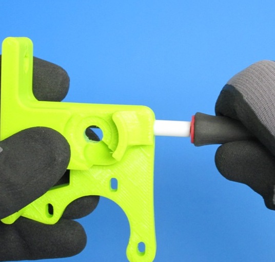
Cut a ~60mm long section of PTFE tubing making sure at least one end is cut to 90degrees
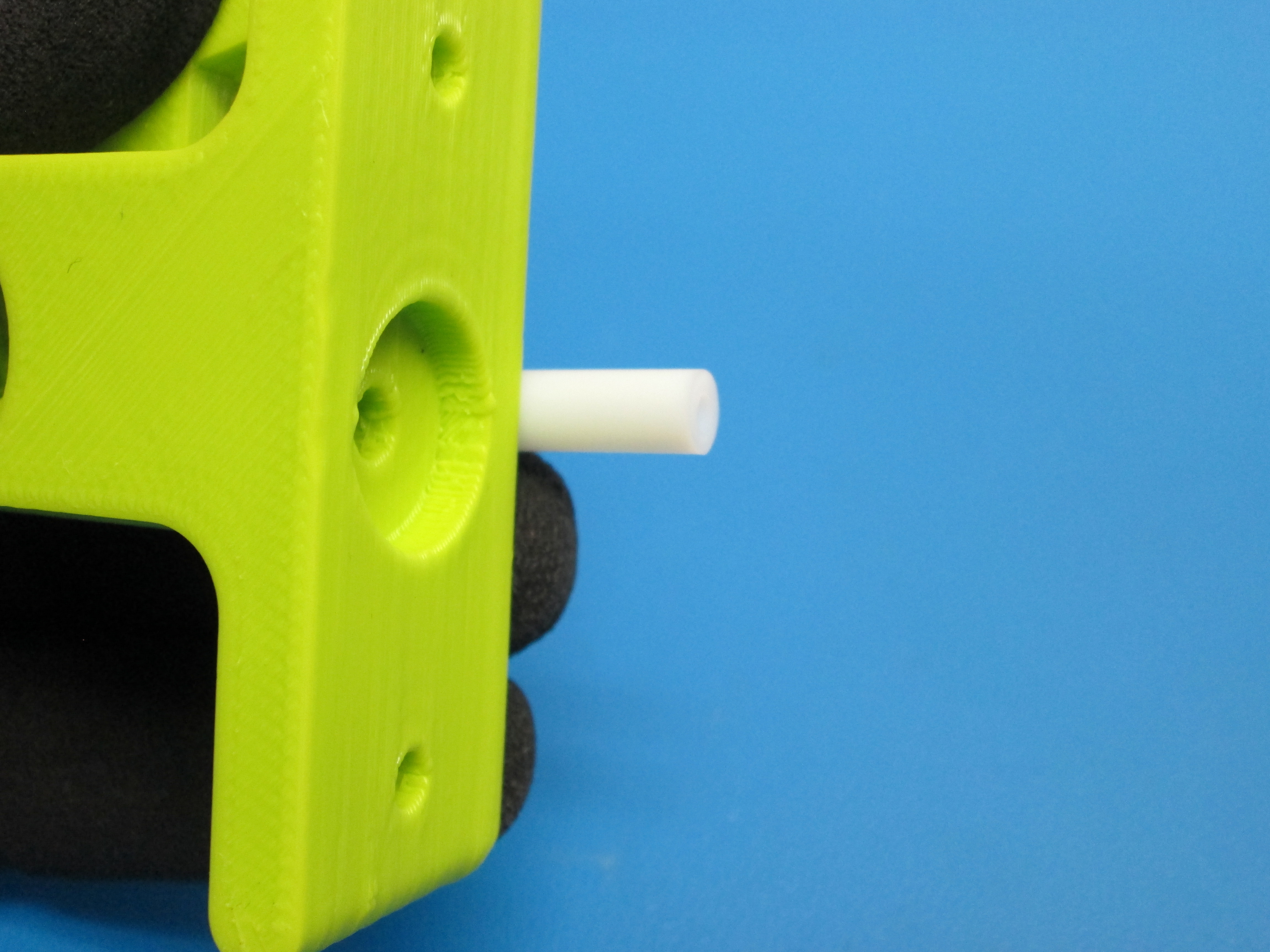
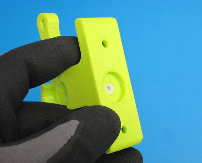
Position the 90degree cut side toward the bottom of the extruder body and press the PTFE tube into the filament feed hole until it is flush with the bottom of the extruder body
Using a 3.5mm drill bit ream out the entire length of the filament feed hole
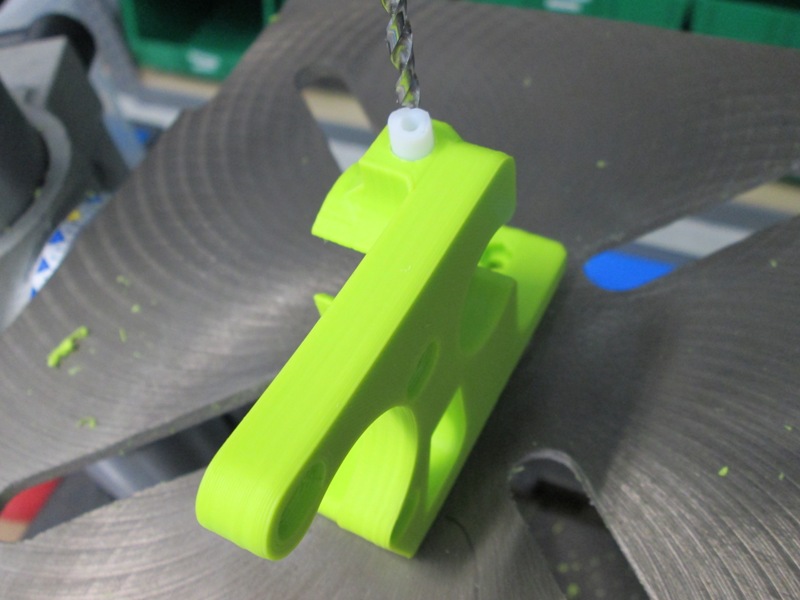
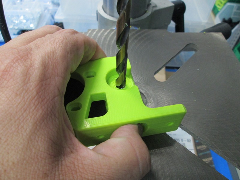
Verify the PTFE is flush with the bottom of the extruder body; Secure the PTFE in place; Align a 8mm drill bit with the center hole of the extruder body, it will be used as a guide for the drill bit.
Drill out the PTFE that occupies the extruder body center
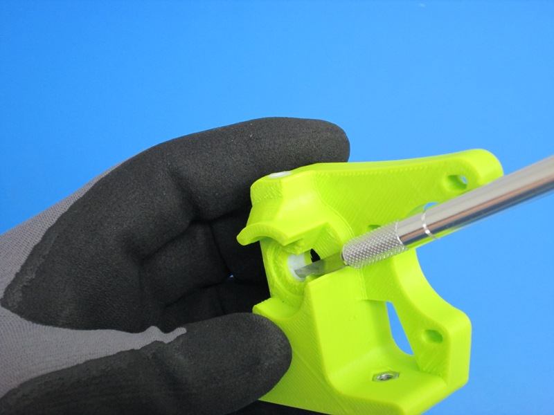
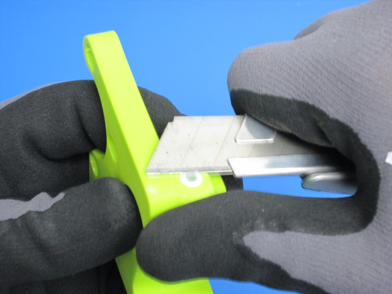
Deburr the trimmed PTFE; using a knife cut off excess PTFE flush from the top of the extruder body

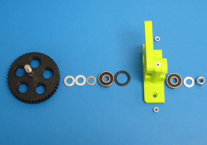
If needed, press hobbed bolt into large herringbone gear.
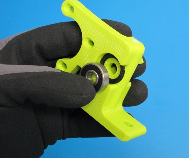
Install 2x M8 washer onto hobbed bolt then a 608 bearing.
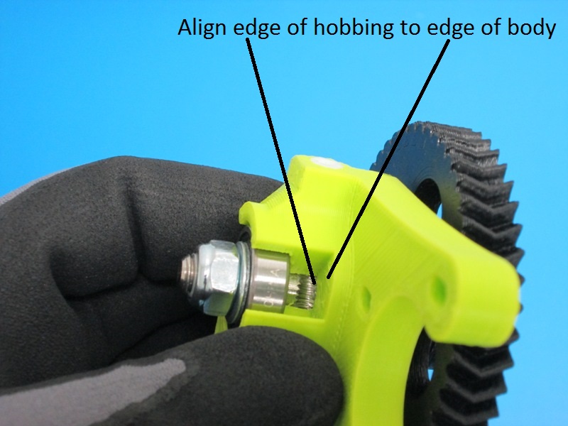
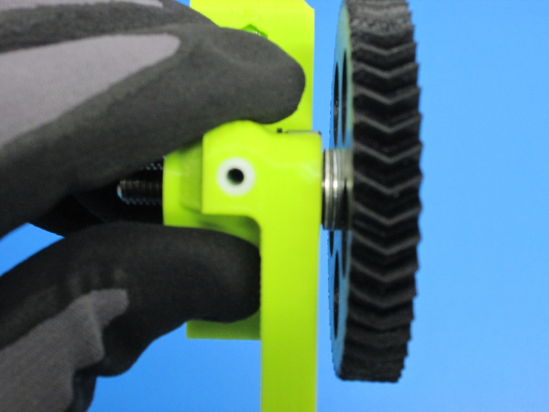
Once installed, does the hobbing on the bolt line up with the small hole going thru the extruder body?
If you need to adjust it's location, you can add either a 0.50mm or 1.0mm shim washer to get the correct spacing

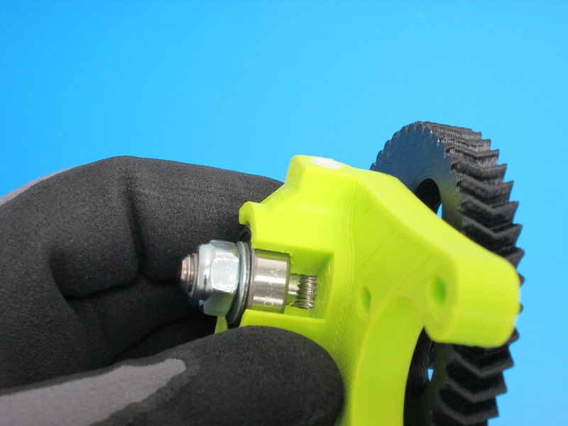
On the opposite side of the gear, add a 608 bearing, M8 Washer and a M8 nyloc nut.
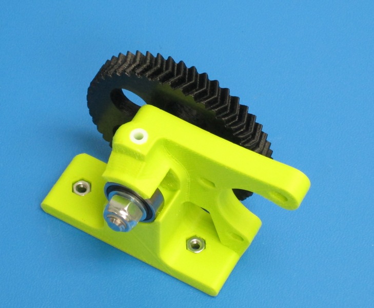
Tighten the Locknut down until the bearing is seated and there is no space between the Nut, Washer and Bearing. Once tightened the washer under the M8 nut should not be able to move.
You may need to go back and add or subtract a 1mm shim washer or .5mm shim washer.
The large gear shouldn't be able to rock back and fourth, but should spin freely.