Open HardwareAssembly Instructions
Guides for installation and assembly of the LulzBot line of products made by FAME 3D LLC.
Guides for installation and assembly of the LulzBot line of products made by FAME 3D LLC.
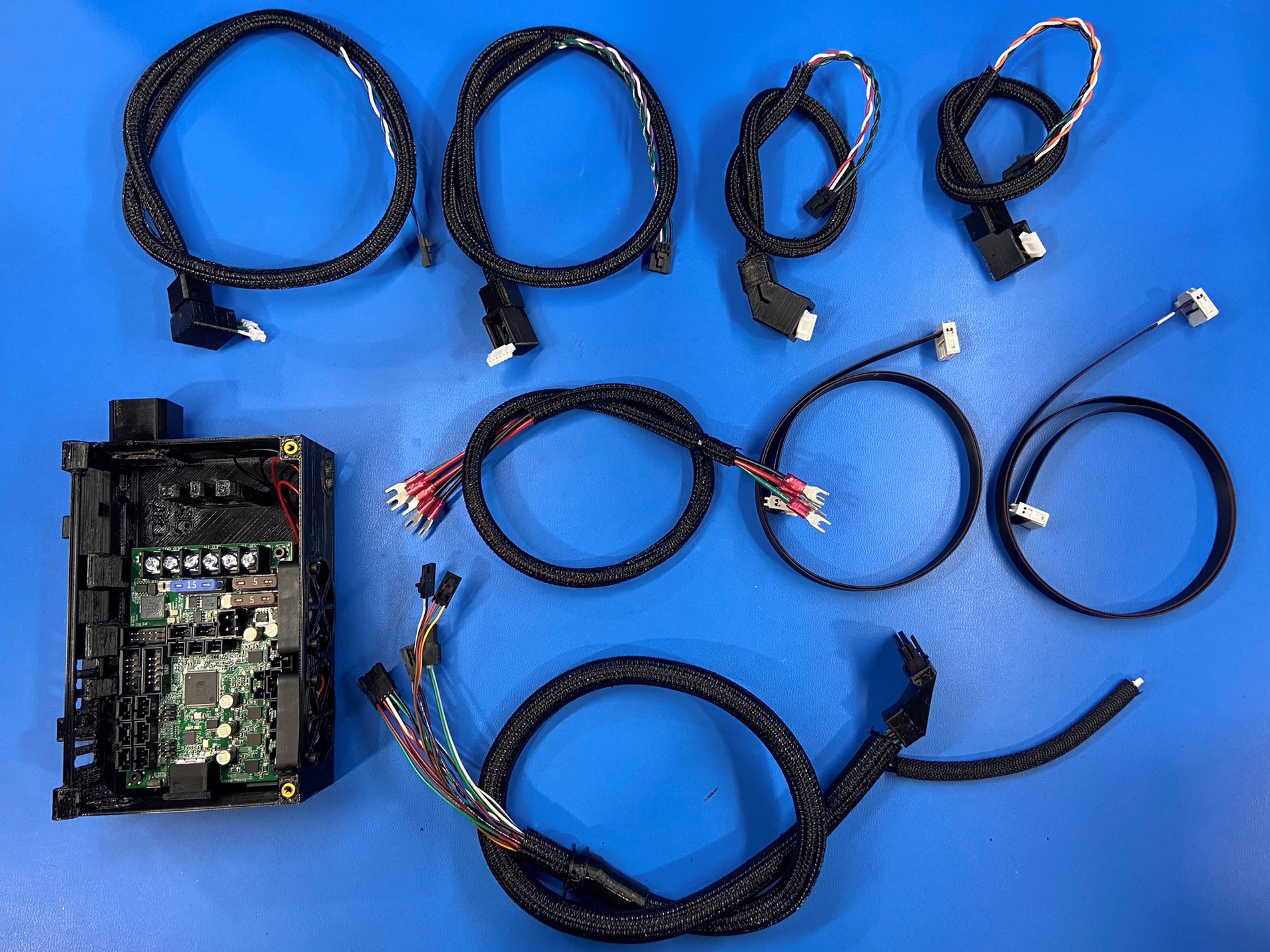
1x- [AS-CB0114] Y Axis Motor Harness
1x- [AS-CB0115] X Axis Motor Harness
1x- [AS-CB0116] Right Z Motor Harness
1x- [AS-CB0117] Left Z Motor Harness
1x- [AS-CB0119] Power Supply to Board Harness
1x- [AS-CB0120] Bed Harness
1x- [AS-CB0130] Standard LCD Harness 1
1x- [AS-CB0131] Standard LCD Harness 2
1x- [EL-HR0194] X Extruder Harness
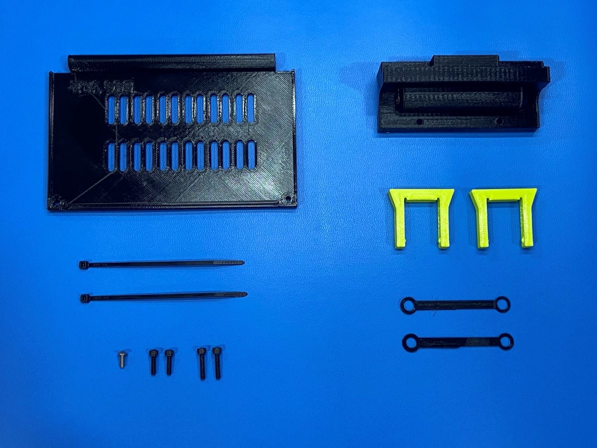
4x- [HD-BT0039] M3x12 SHCS, Black-Oxide
1x- [HD-BT0104] M3x8 BHCS, SST
2x- [HD-MS0588] 4" Black Standard Cable Tie
1x- [PP-GP0549] Control Box Cover
2x- [PP-GP0565] CB Clip
1x- [PP-GP0571] Control Box Frame Mount
2x- [PP-GP0622] Control Box Clip Tether
Control Box Assembly
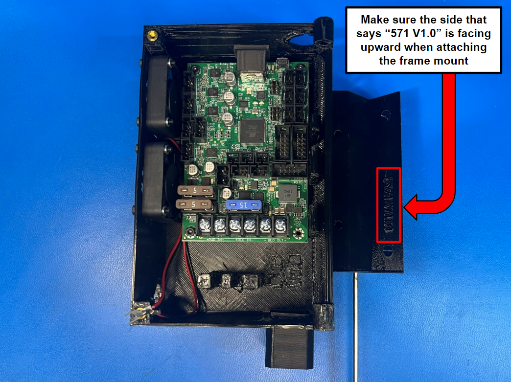
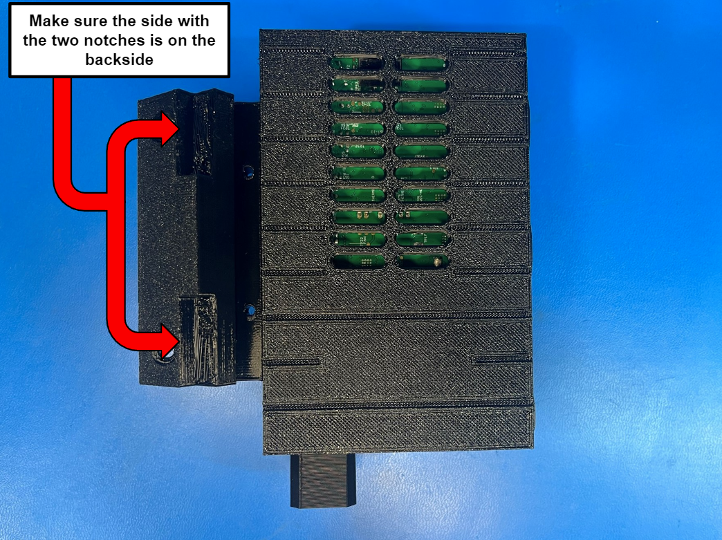
Using 2x M3x12 SHCS [HD-BT0039] attach the control box frame mount [PP-GP0571] to the control box hinge.
Note: Make sure the orientation of the frame mount is correct, follow [reference#1] and [reference#2].
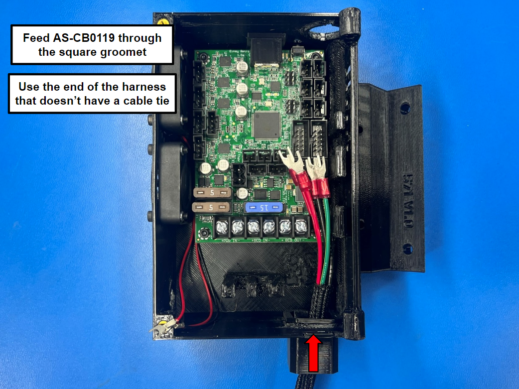
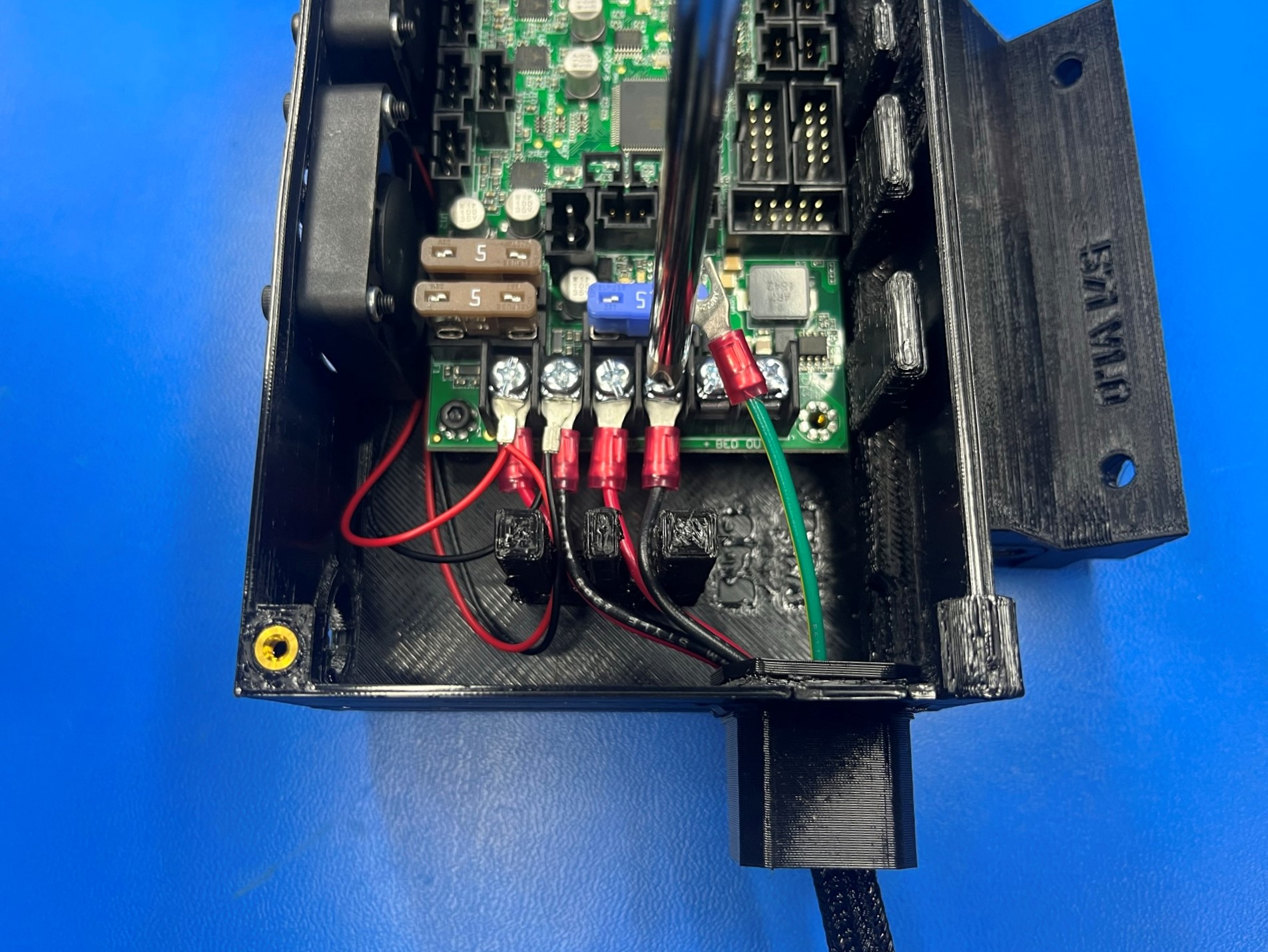
Feed the power supply to board harness [AS-CB0119] through the square grommet located on the bottom wall of the control box case.
Note: make sure to use the end of the harness that doesn't have a cable tie.
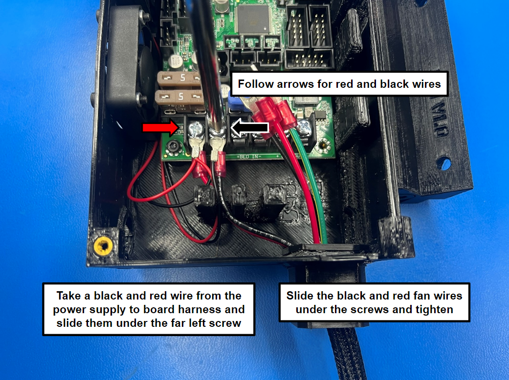
Then take one red wire from the power supply to board harness and slide it under the far left screw, then repeat with one black wire and slide it under the next screw.
Note: route both wires through the left opening on the wire comb.
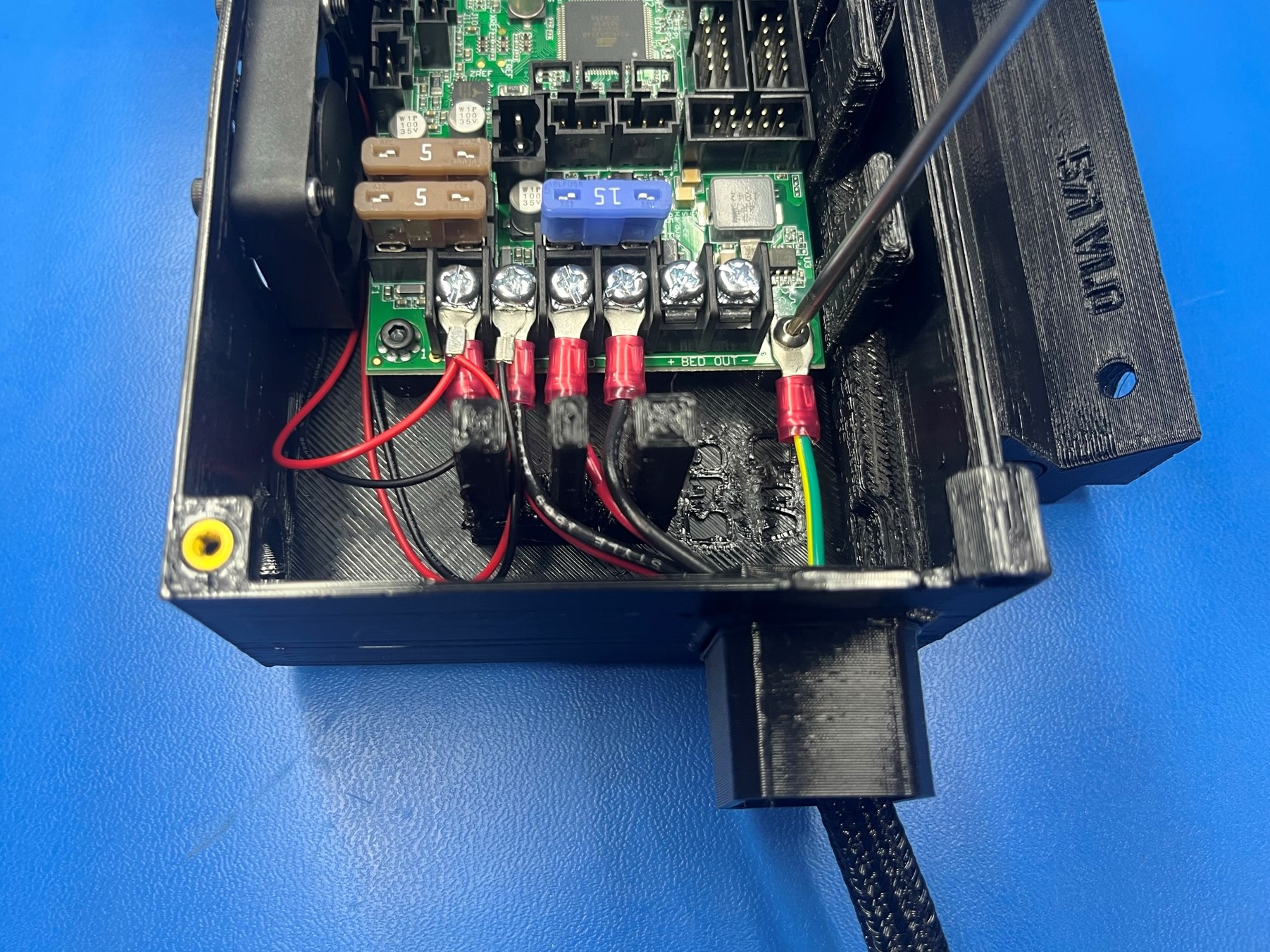
Secure the green ground wire to the board using 1x M3x8 BHCS [HD-BT0104]
Now take the red and black fan wires and slide them over the red and black wires, that were just placed and tighten the screws down.
Make sure to pull on the wires to verify they are secure.
Take one red wire and slide it under the third screw from the left and tighten. Repeat for the last black wire with the next screw.
Note: route both wires through the right opening on the wire comb.
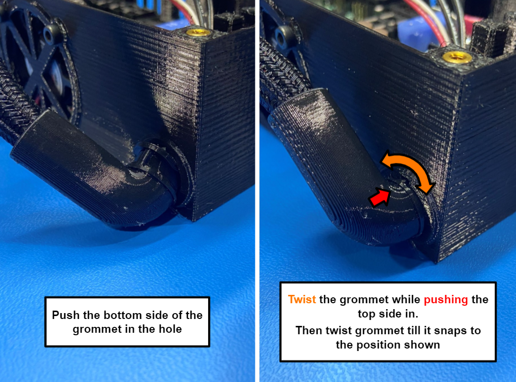
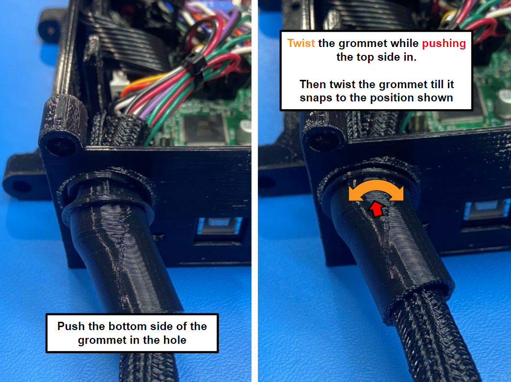
Feed the bed harness [AS-CB0120] through the hole on the left wall, then push the bottom side of the grommet into the hole and then twist and push the top side in place [reference#3]
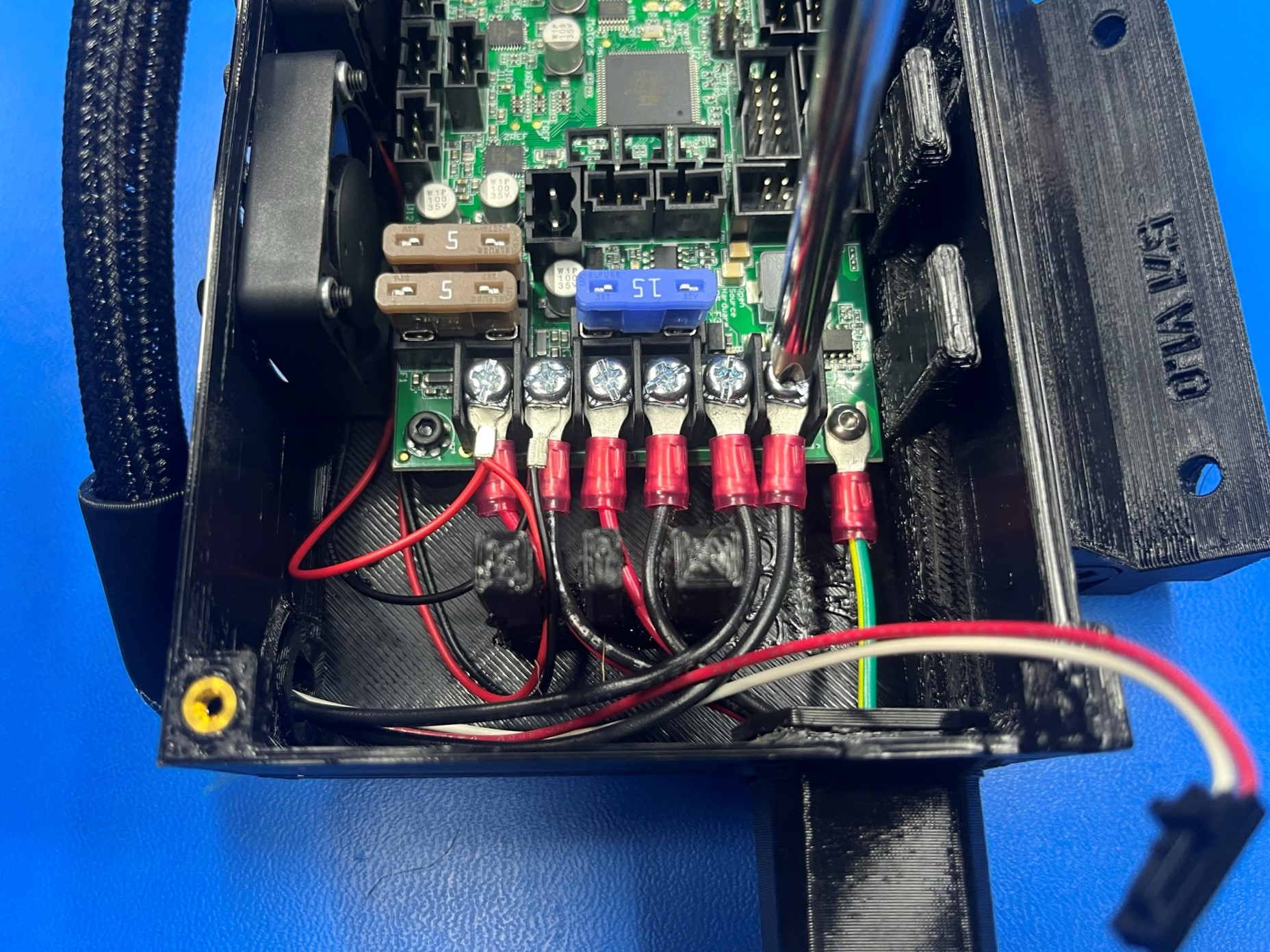
Take the two black wires and slide them under the last two open screws (far right screws) then tighten.
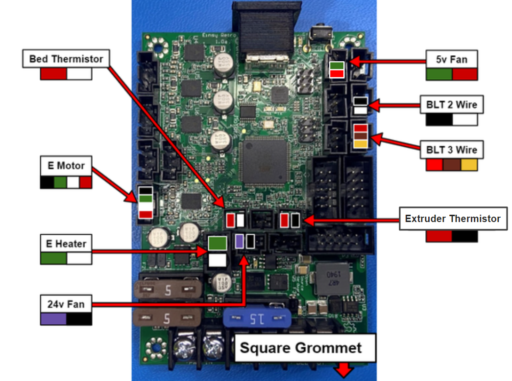
Then connect the bed thermistor wire (red and white wire) to board.
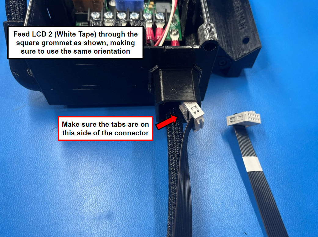
LCD 2 is the harness that has white tape on one end
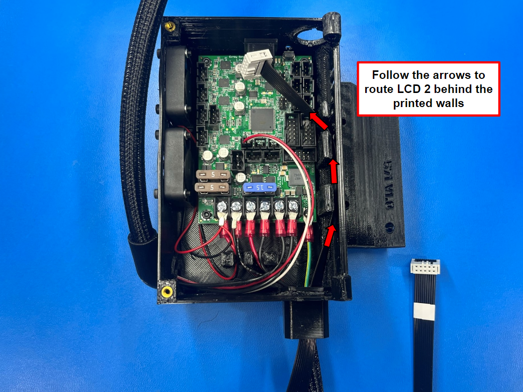
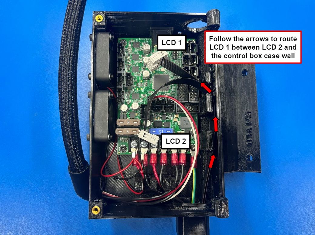
Take the end of the standard LCD harness 2 [AS-CB0131] that has the tabs on the same side as the wires and feed it through the square grommet. Then route the wire behind the tabs on the right side of the box. Make sure its behind the first two tabs and then on the outside of the last smaller tab.
Make sure the end of the LCD harness that has the white tape is outside of the control box case!
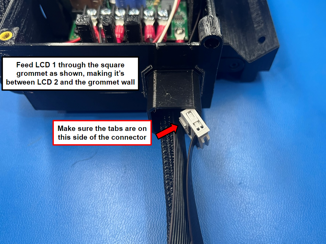
Now take standard LCD harness 1 [AS-CB0130] and repeat the process with LCD 2 being on the inside or left side of LCD 1.
Note: make sure to take the end of LCD 1 that has the tabs on the same side as the wires.
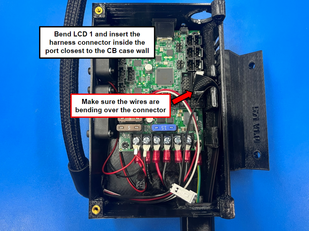
Bend LCD 1 over so that you can connect it to the board as shown in [reference#4].
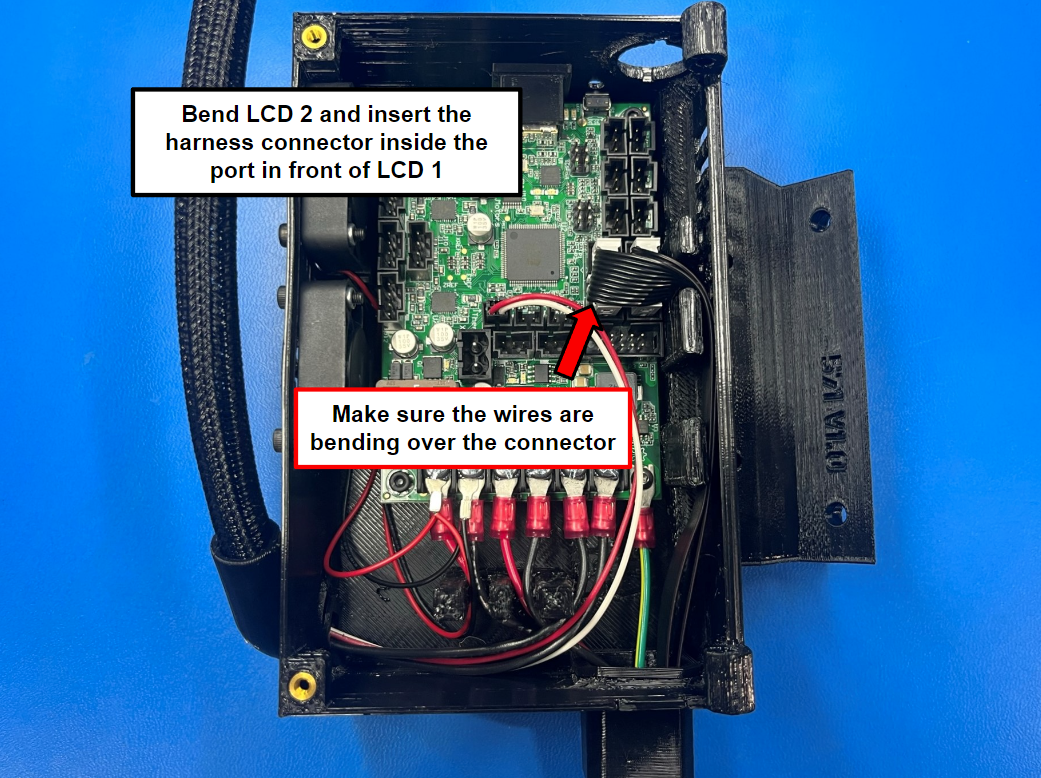
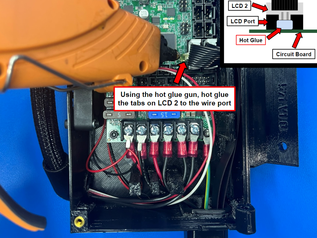
Repeat process for LCD 2 making sure the wires are holding LCD 1 in place, and then using the hot glue gun place hot glue over the connector tabs and the port that is mounted to the board.
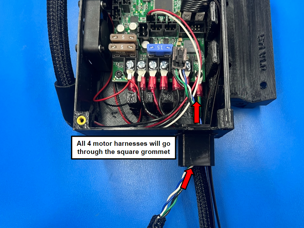
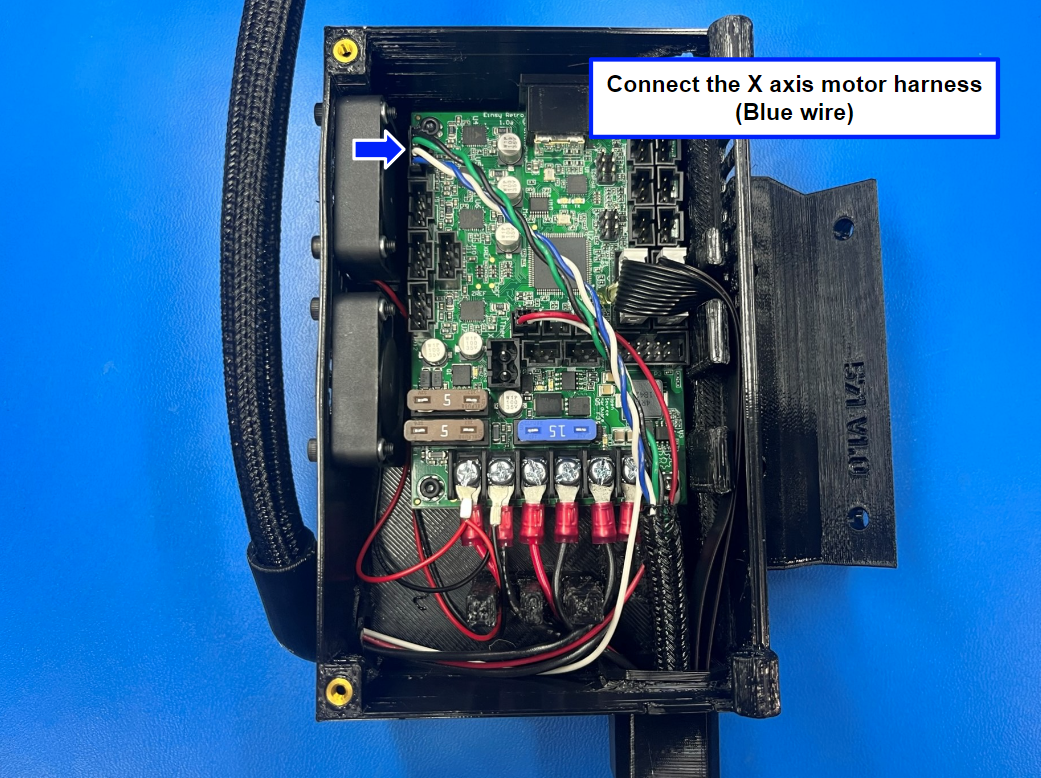
Take the X axis motor harness [AS-CB0115] and route it through the square grommet and connect it to the top motor port on the control board.
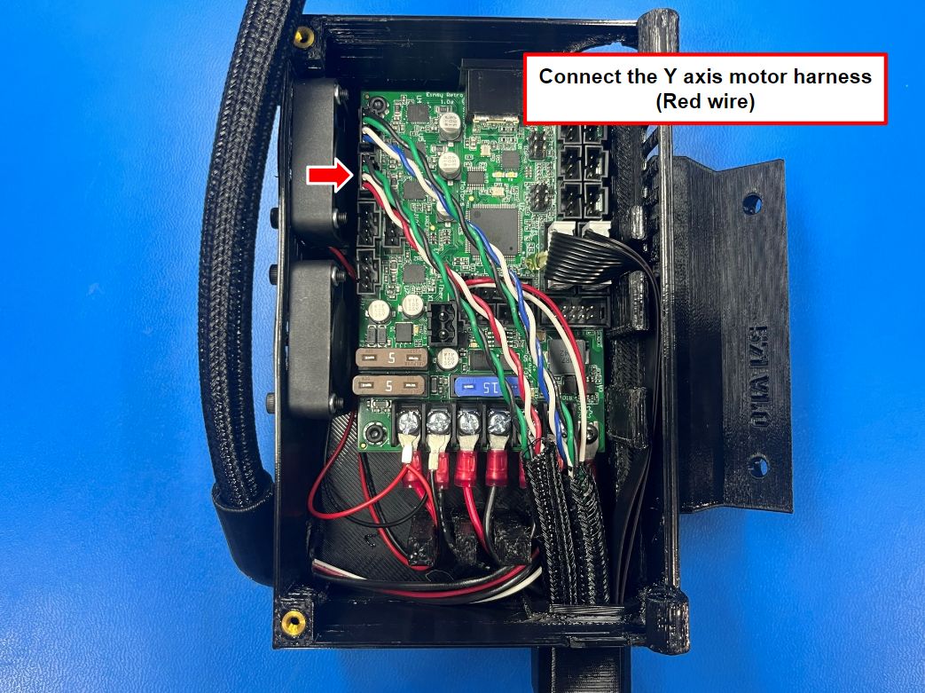
Now take the Y axis motor harness [AS-CB0114] and repeat the process with the next motor port on the control board.
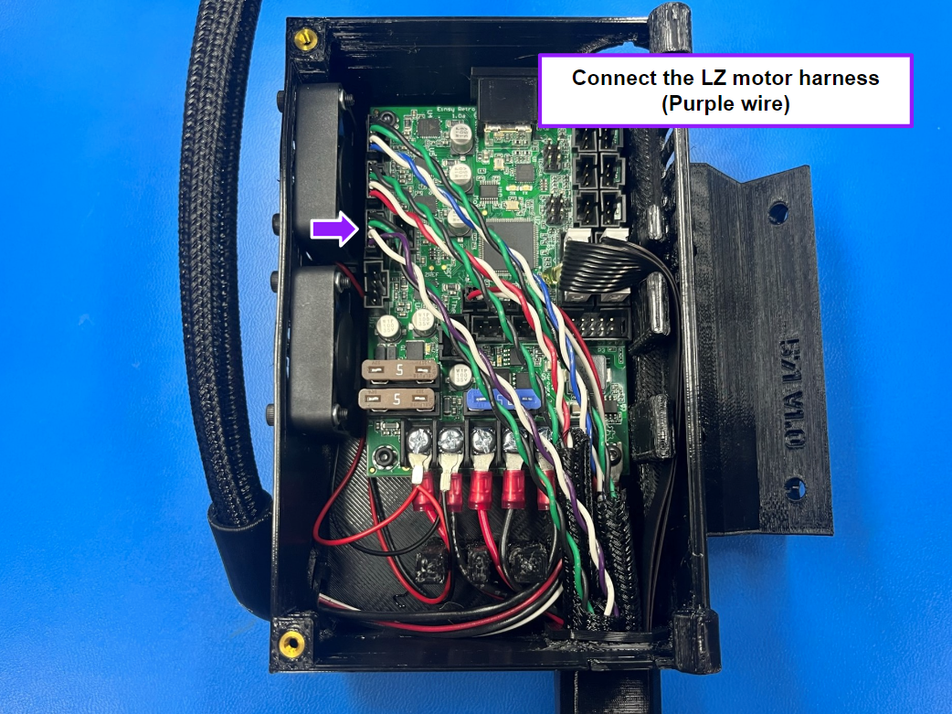
Next we are using the left Z motor harness [AS-CB0117] and feed it through the square grommet and place it in the left motor port on the board that is directly under the Y axis harness.
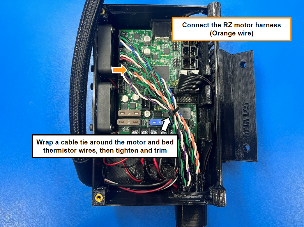
Finally take the right Z motor harness [AS-CB0116] and repeat the process with the motor port on the right of the LZ motor harness.
Note: You may need to rearrange the wires inside the square grommet in order to fit all of the harnesses, you can also use a pliers or screw driver to push the harnesses through the grommet.
Once all the motor wires are connected to the board wrap a 4" cable tie [HD-MS0588] around the motor harnesses and the bed thermistor wire and then tighten and trim the cable tie.
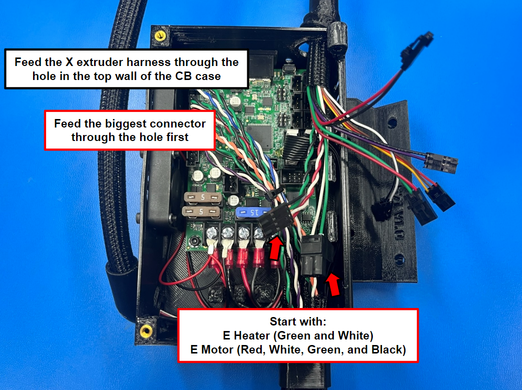
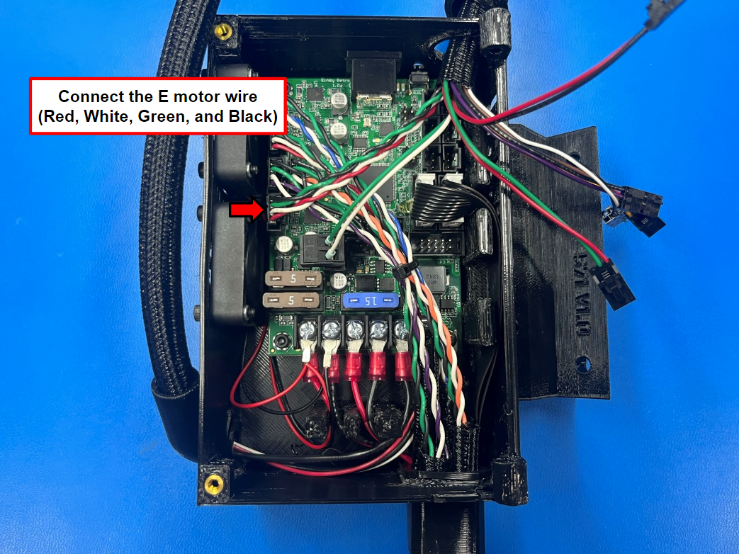
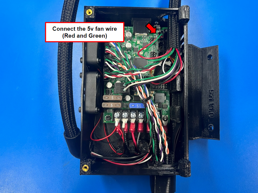
Feed the X extruder harness [EL-HR0194] through the hole in the top wall of the control box case.
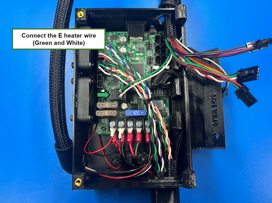
Note: make sure to start with the E heater wire (Green and White) and the E motor wire.
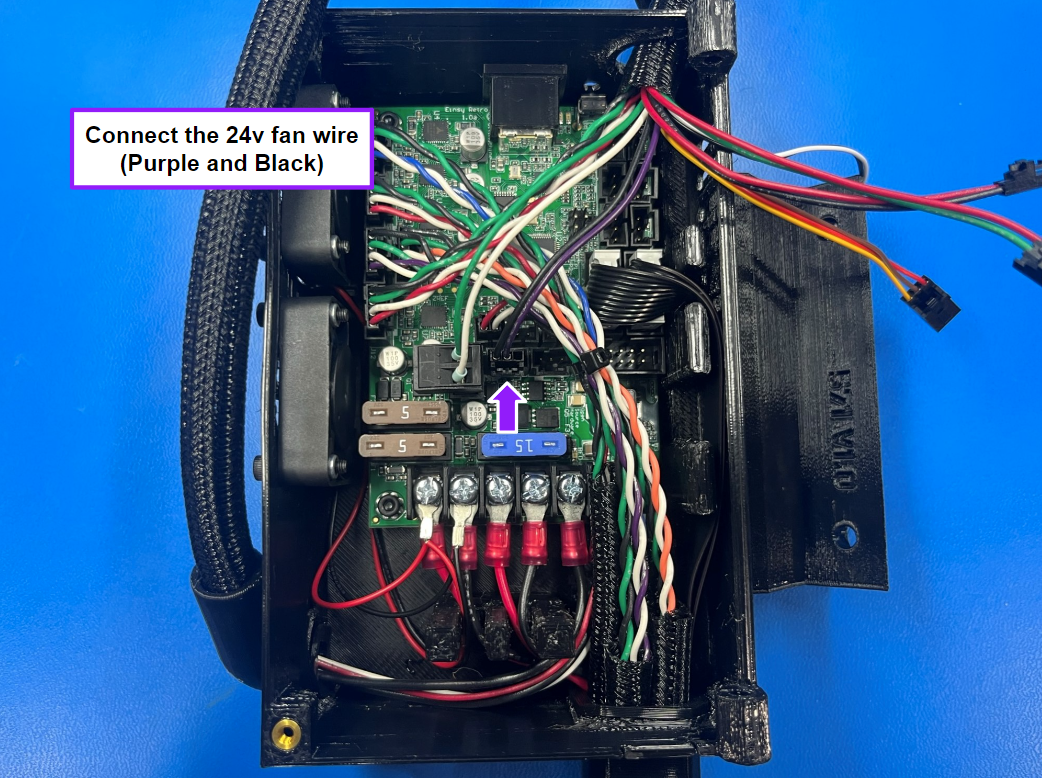
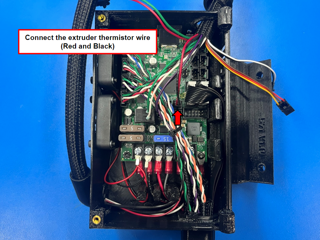
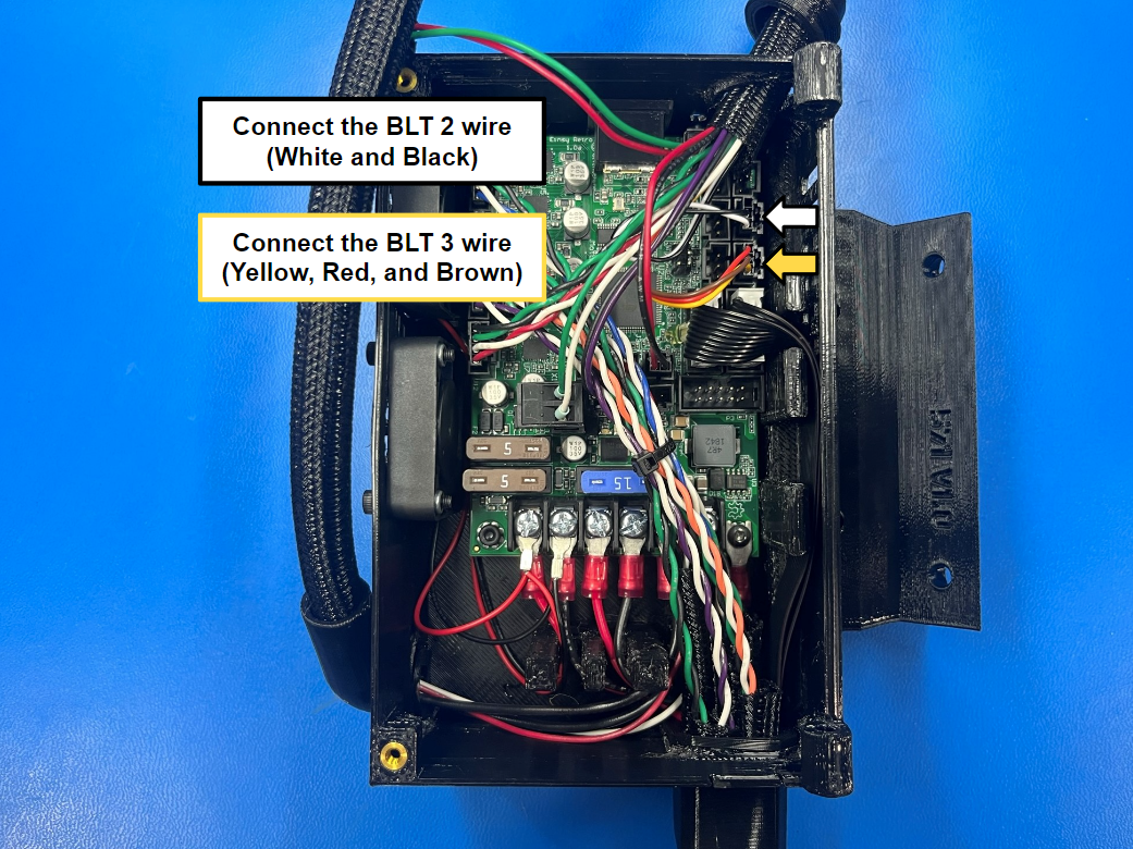
Following the pictures, connect the following wires:
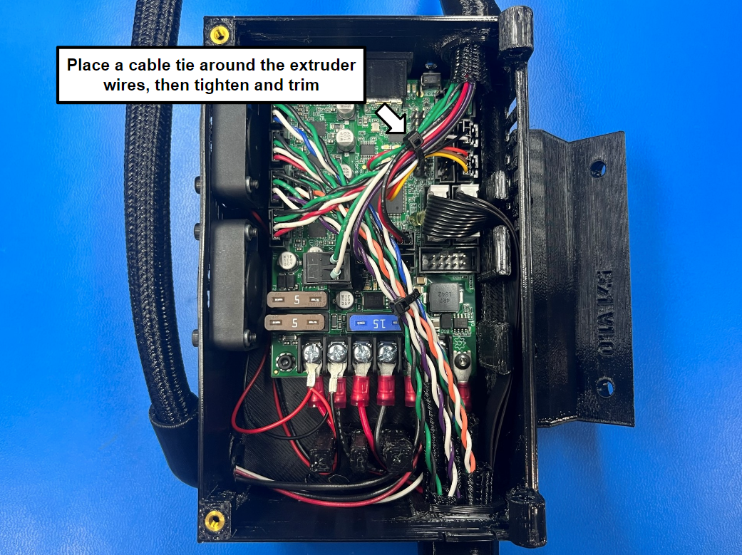
Once all wire are connected place a cable tie around all the X extruder wires.
Note: you can loop the 5v fan, BLT 2, and BLT 3 wires inside the cable tie to make the inside of the box look cleaner.
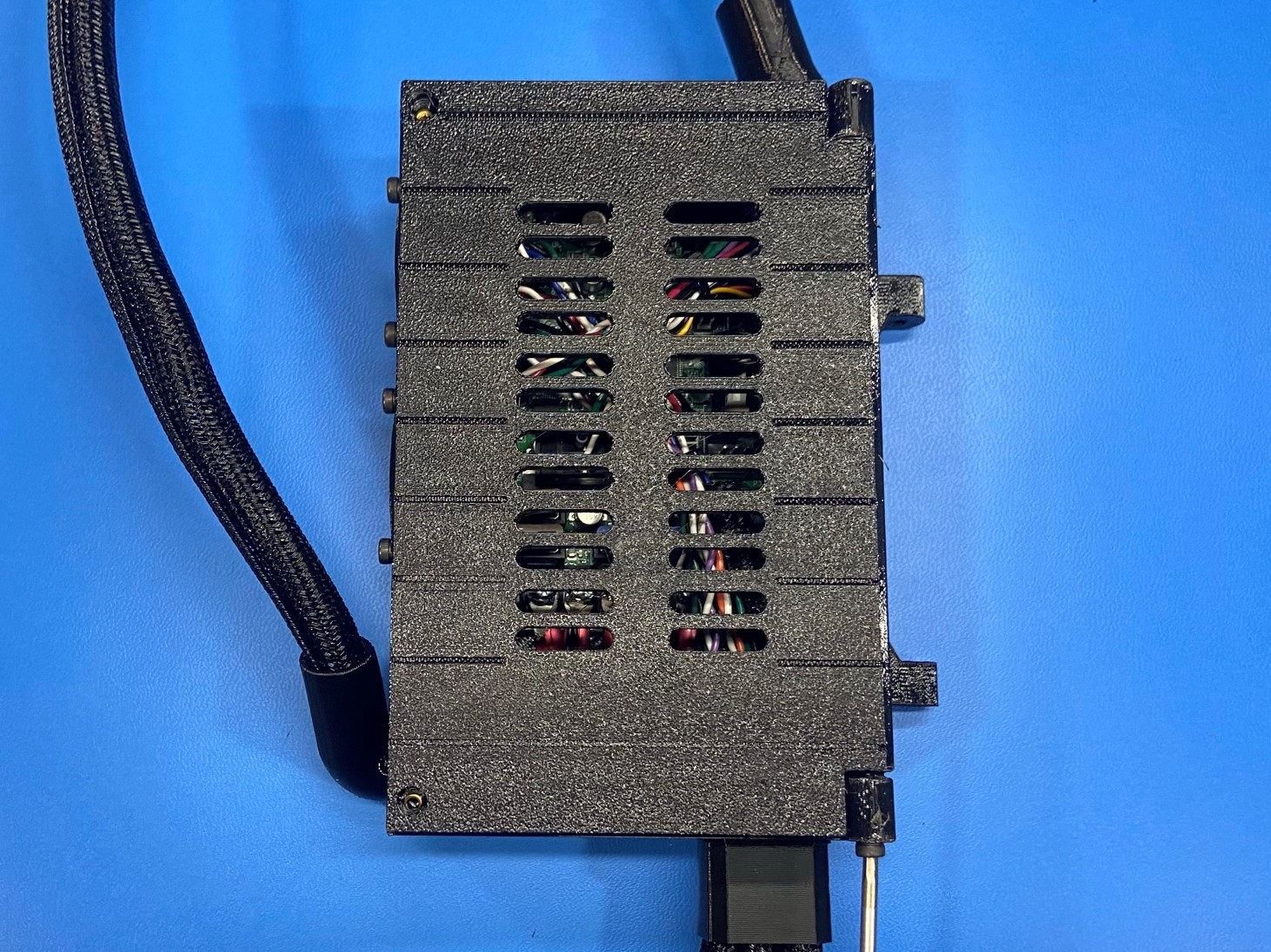
Using 2x M3x12 SHCS [HD-BT0039] attach the control box cover [PP-GP0549] to the top side of the control box case.
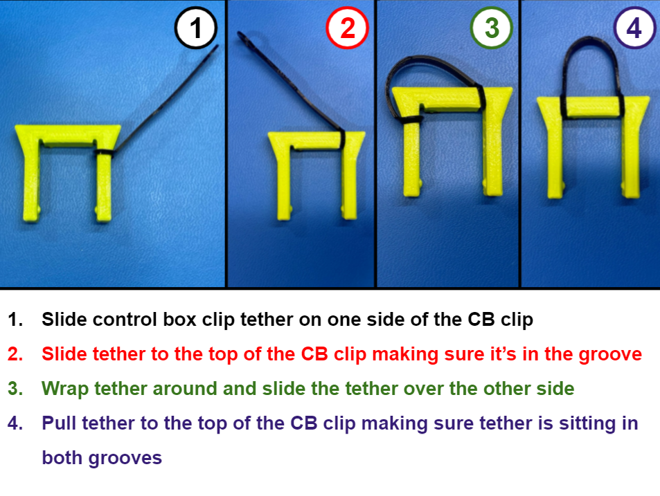
Using 1x CB clip [PP-GP0565] and 2x control box clip tether [PP-GP0622] follow [reference#5] for assembling the CB clips.
Then repeat for the second CB clip.
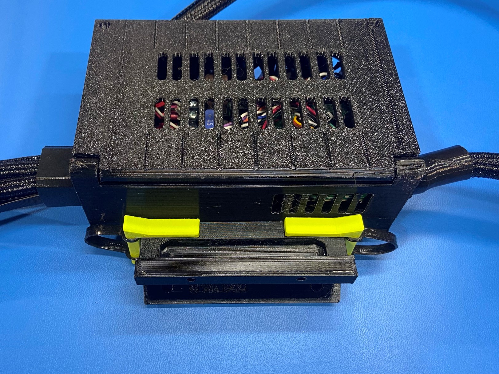
Once both CB clips are assembled place them around the control box hinge and the control box frame mount.
Note: Make sure both clips snap into place.