Open HardwareAssembly Instructions
Guides for installation and assembly of the LulzBot line of products made by FAME 3D LLC.
Guides for installation and assembly of the LulzBot line of products made by FAME 3D LLC.
Before we begin exploring the user interface of the 9380 used to control how the wire is processed we must first learn to properly load raw material into the machine.
Refer to the Cut List found near the machine to determine which raw cable material is to be processed.
Open the safety cover, and turn the feeding unit opener clockwise to the open position. Do not attempt to turn the feeding unit opener past the locked open position as it will damage the unit.
Select the appropriate guides for the raw material selected. The wire must slide freely through the guides.
Immovable Guide Left & Right
Open the Safety Cover
Push the Lever (1) downwards
Remove the Guide (2) from the holder
Grasp the required guide so that the flat surface (3) is positioned upwards
Push the Guide into the holder -The lever (1) must snap in
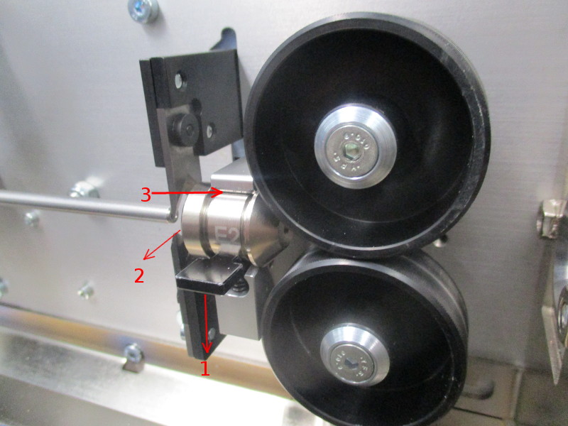
Swivel Guide
Loosen the thumb screw (1)
Grasp the guide (2) and remove it from the holder
Slide the required guide (2) into the holder
Tighten the thumb knob (1)
Load the spool of raw cable material onto the cable reel holder of the PreFeeder, with the spooling direction of the reel facing counter-clockwise. Lock in place with the centering cones. Make sure the cable reel will spin freely.
Open the Quick Lock on the PreFeeder’s transport unit by flipping the toggle upwards.
Feed the raw material through the transport unit.
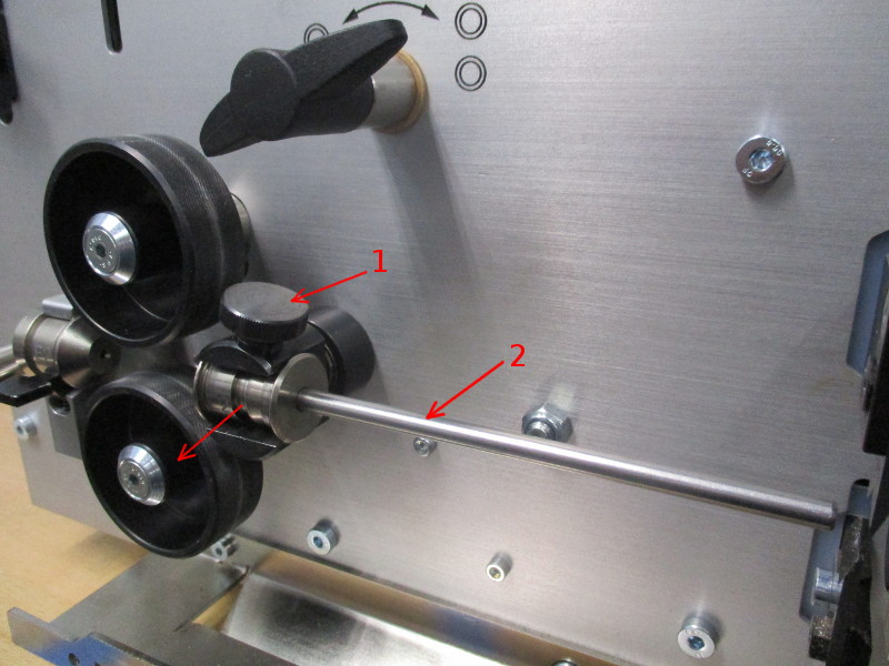
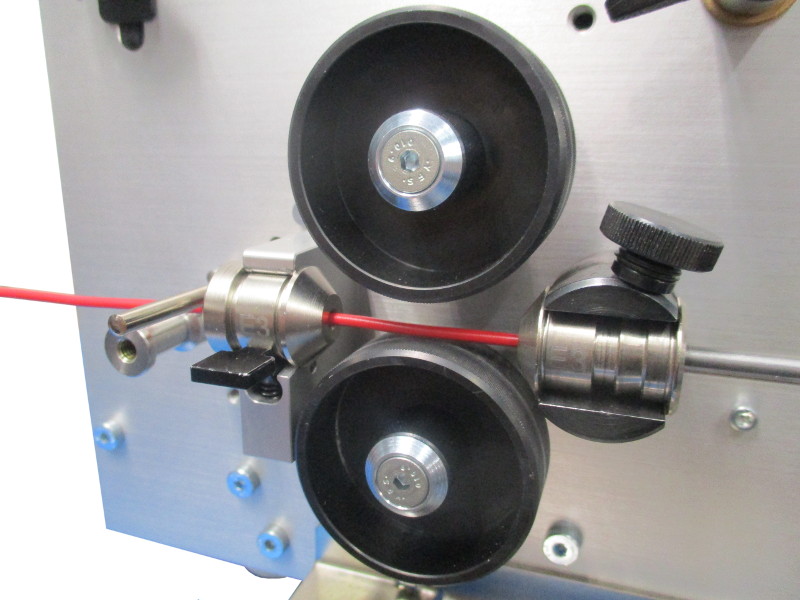
Turn the top and bottom locking levers on the accumulator rollers clockwise to open.
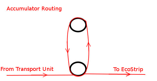
The diagram, also visible on the Operator Panel, shows how the raw material is routed through the Accumulator.
Route the cable around the Accumulator lower dancer roller first, counter-clockwise, and then around the top guide roller before again passing the lower roller.
For smaller gauge wire (<16AWG) you will route around the accumulator twice before continuing to the EcoStrip. This ensures proper tension to lift the lower dancer roller.
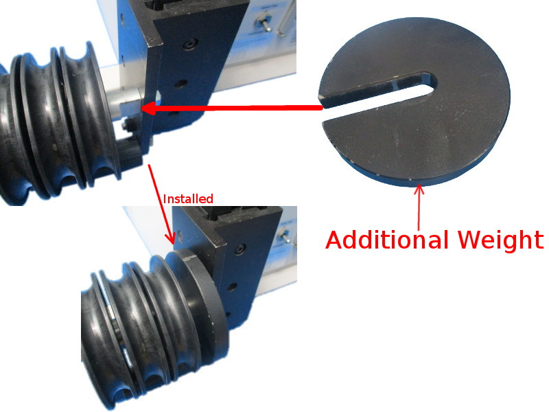
To achieve enough downward force on the dancer roller while larger gauge wire is being processed (>16AWG), the additional weight is used. See picture for installation of the additional weight.
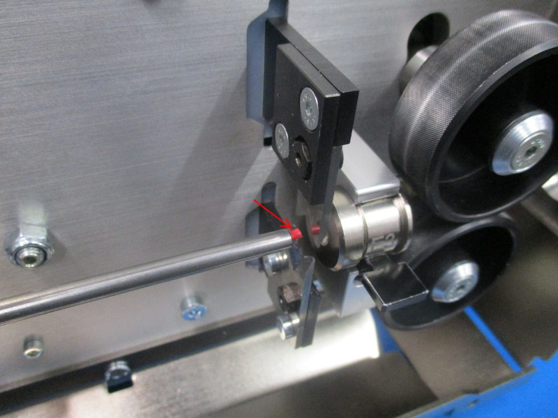
Lift up the Wire End Monitoring Switch and feed the raw material through the first guide, and then between the left feed rollers.
Feed the raw material through the swivel guide until a small amount of wire can be seen at its right end near the blades. Do not feed through or past the blades.
Close the feeding unit opener by turning the lever counter-clockwise.
Close the safety cover.
Lightly tension the cable in the PreFeeder by hand-spinning the spool clockwise, and then lock the transport belts with the Quick Lock.
If the Quick Lock is too difficult to engage you must first loosen the Adjuster Knob on top of the PreFeeder’s Transport Unit.
Tighten the Adjuster Knob until the transport belts have firm grip on the raw material and will not allow it to slip.

On the touch screen display, select the raw material loaded in order to access the Production Commands Menu.
The gap between the right feed rollers must be adjusted whenever there is a change in raw material in order to ensure accurate processing of the wire. This gap is adjusted manually however with guided assistance through the Graphical User Interface.
Select the Production Commands Menu (see picture)
In the menu that appears, select “Adjust” (see picture)
In the opened dialogue, press “Feed” until wire is present between the right feed rollers. Follow the on screen prompts until the adjustment is complete. The wire used to adjust is then automatically cut and ejected, giving us a proper “Zero Cut” to begin processing from.
Contact pressure between the feed rollers does not often need adjustment unless slippage occurs during processing, causing inconsistent cut/strip lengths. Usually a value around 3 is sufficient.
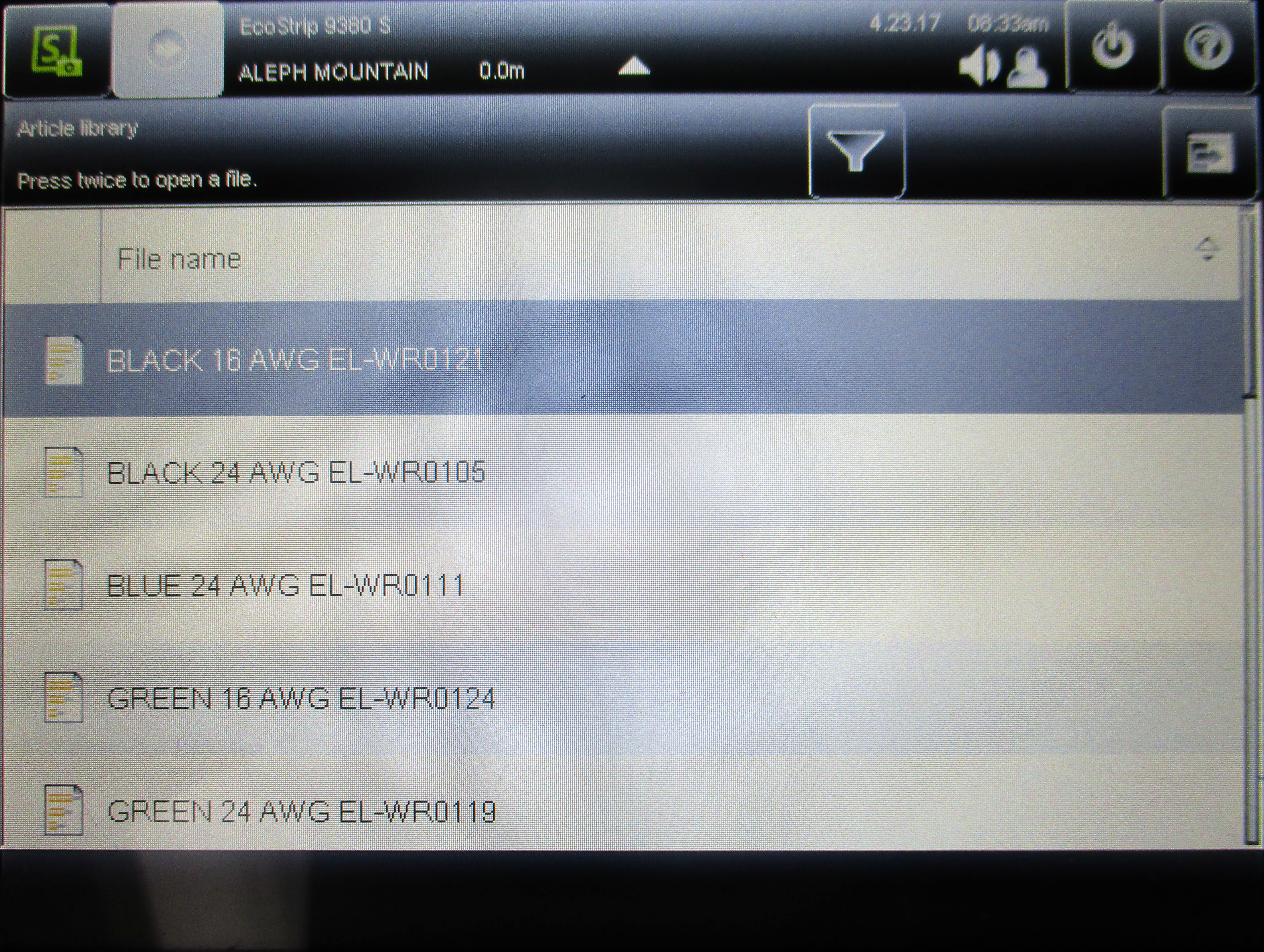

All needed articles from the loaded raw material should be cut before loading another raw material.
From the article list select the article you wish to cut first. This brings up the properties of the selected article.
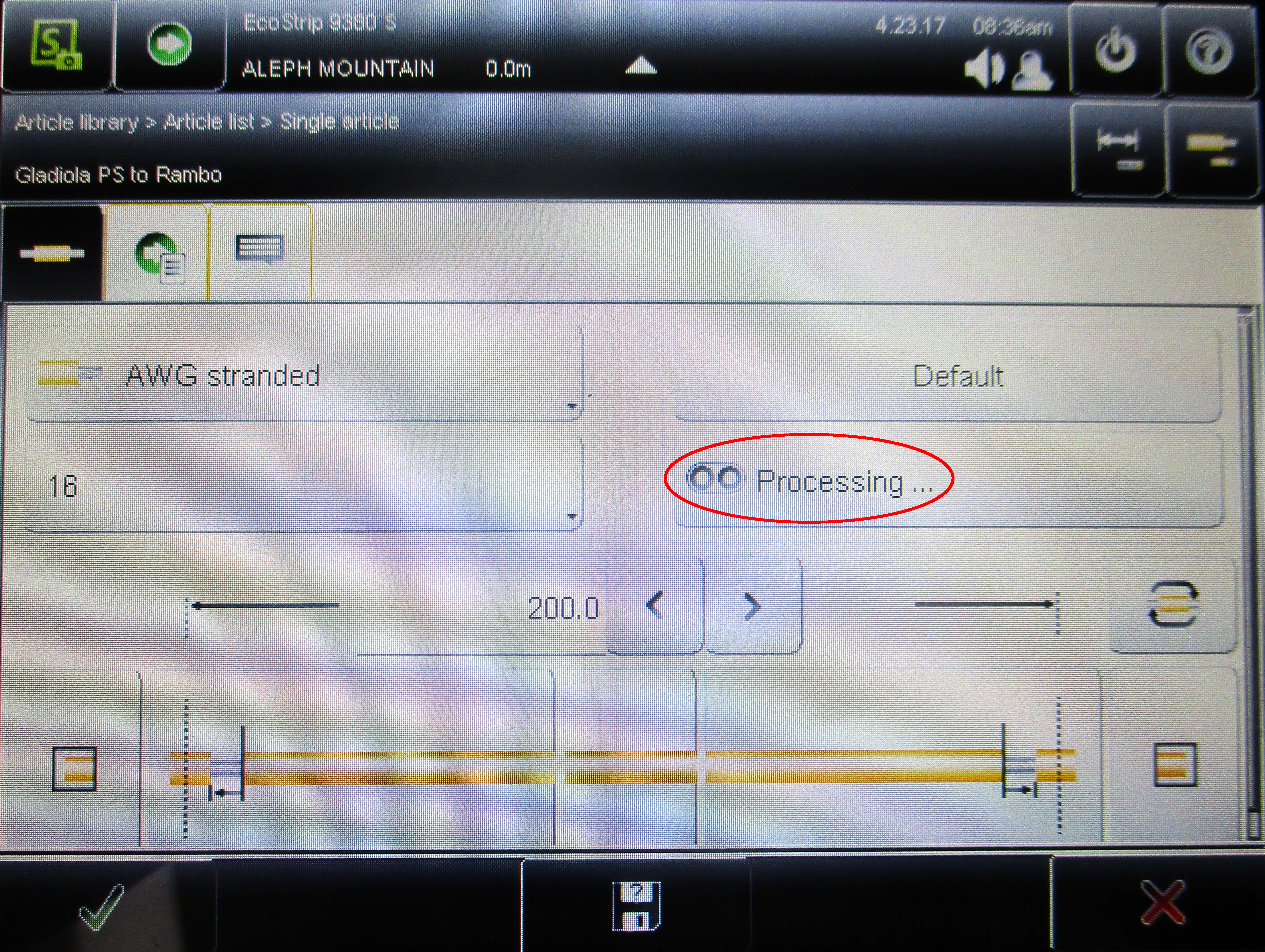
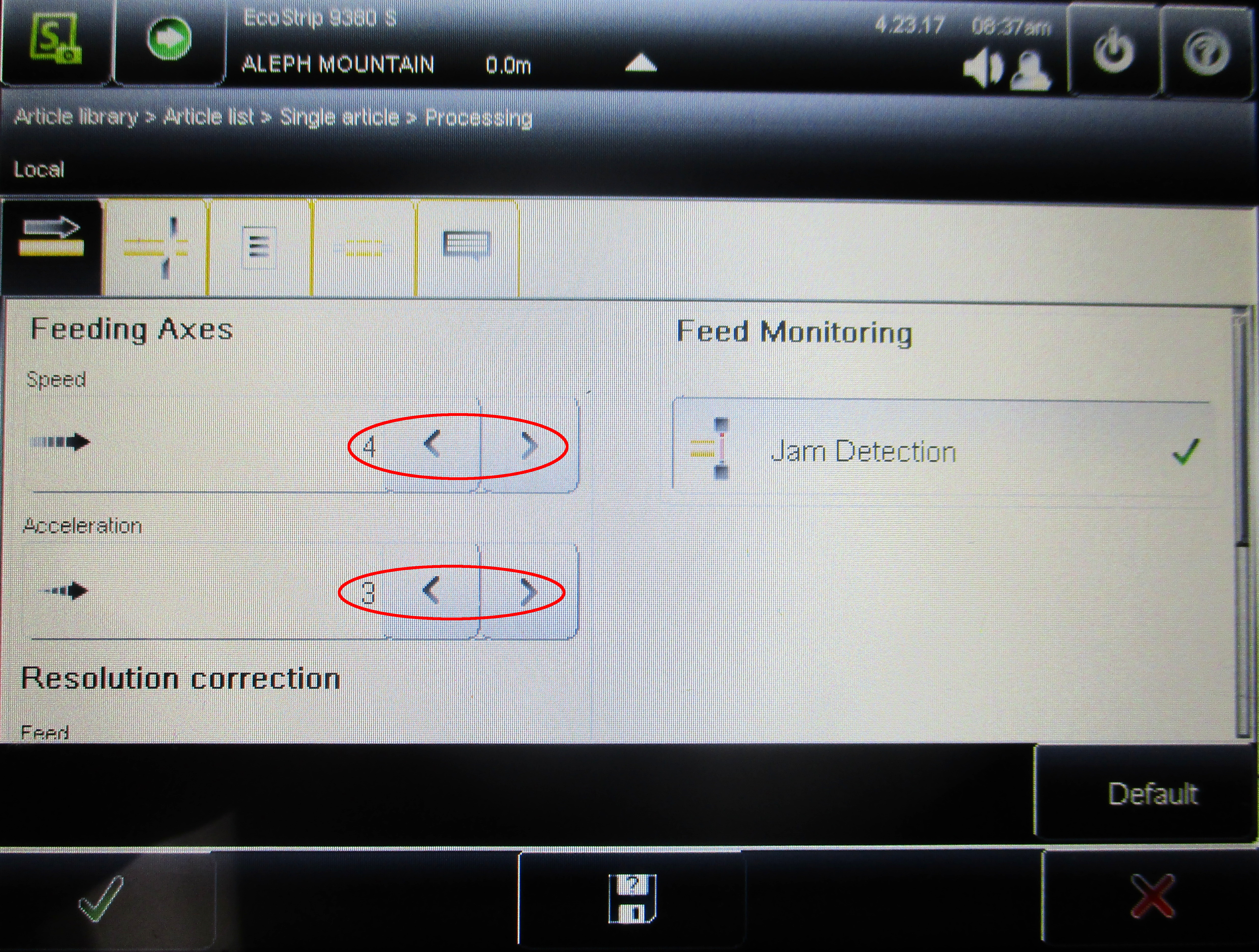
Before we begin processing wire, we’ll want to adjust a few basic settings in the processing menu.
Select “Default” above “Processing” to clear any adjustments performed previously.
Reduce the Speed and Acceleration of the feeding axis from the default value by one. Acceleration should always be lower than the Speed.
Adjusting this speed will slow operation of the machine slightly but greatly increases its accuracy.
Select the green check mark in the lower left of the screen to save these changes and return to the article screen.
Verify the desired length, as well as the strip and pull off lengths of the article to be processed with the printed Cut List. Pull of length should be about half of the strip length.
Before starting a batch of wires we must ensure the wires will be cut to specifications throughout the batch. We will also verify wires cut mid-batch as well as at the end of each batch. No other activities are permitted while processing wire, you must remain attentive to the process at all times.
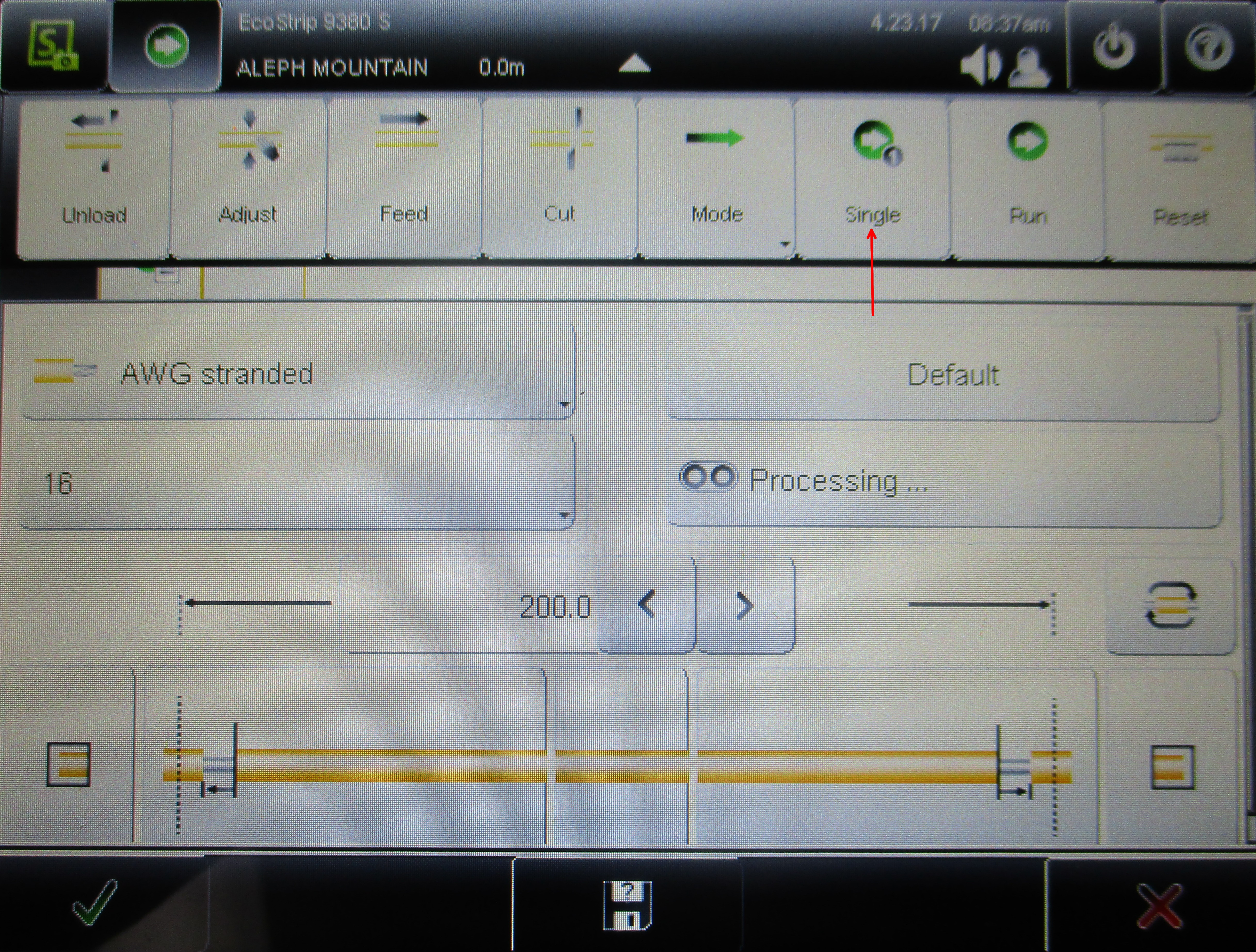
You will now run 3 to 5 wires to verify accurate cuts and strips.
Open the Production Commands menu and select “Single”
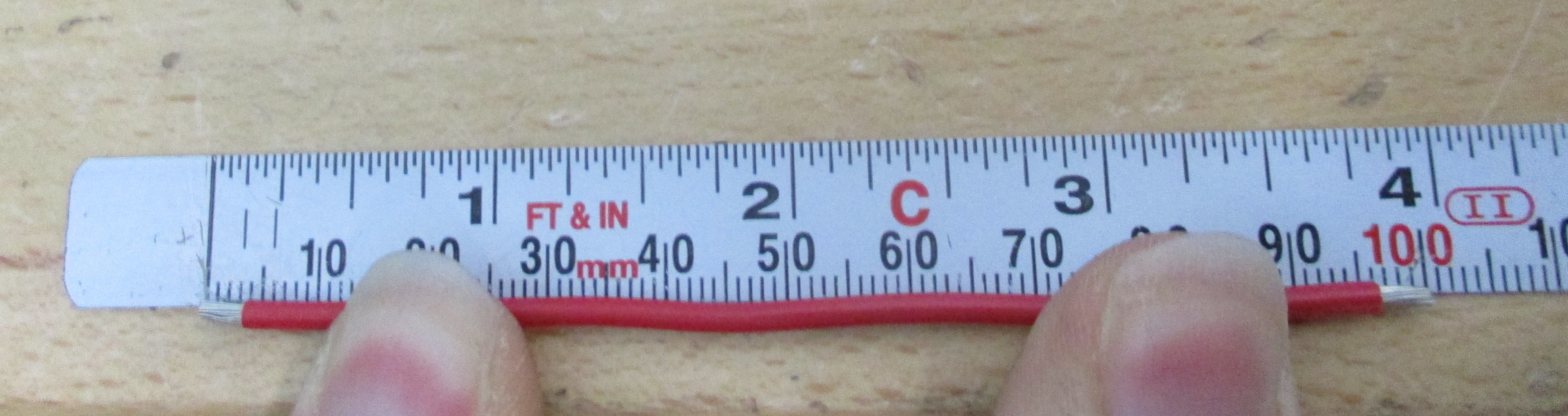
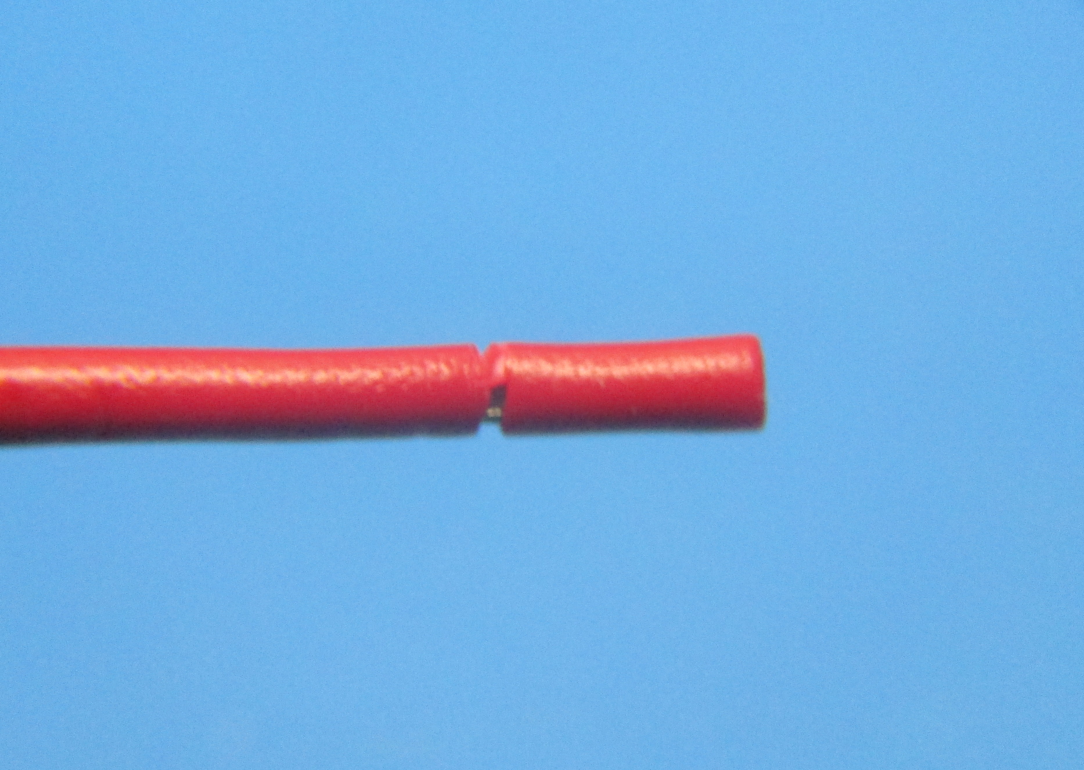
Remove the slugs from the stripped ends of the processed wire and measure it with the ruler fixed to the table.
Check both the overall length as well as the length of the stripped ends.
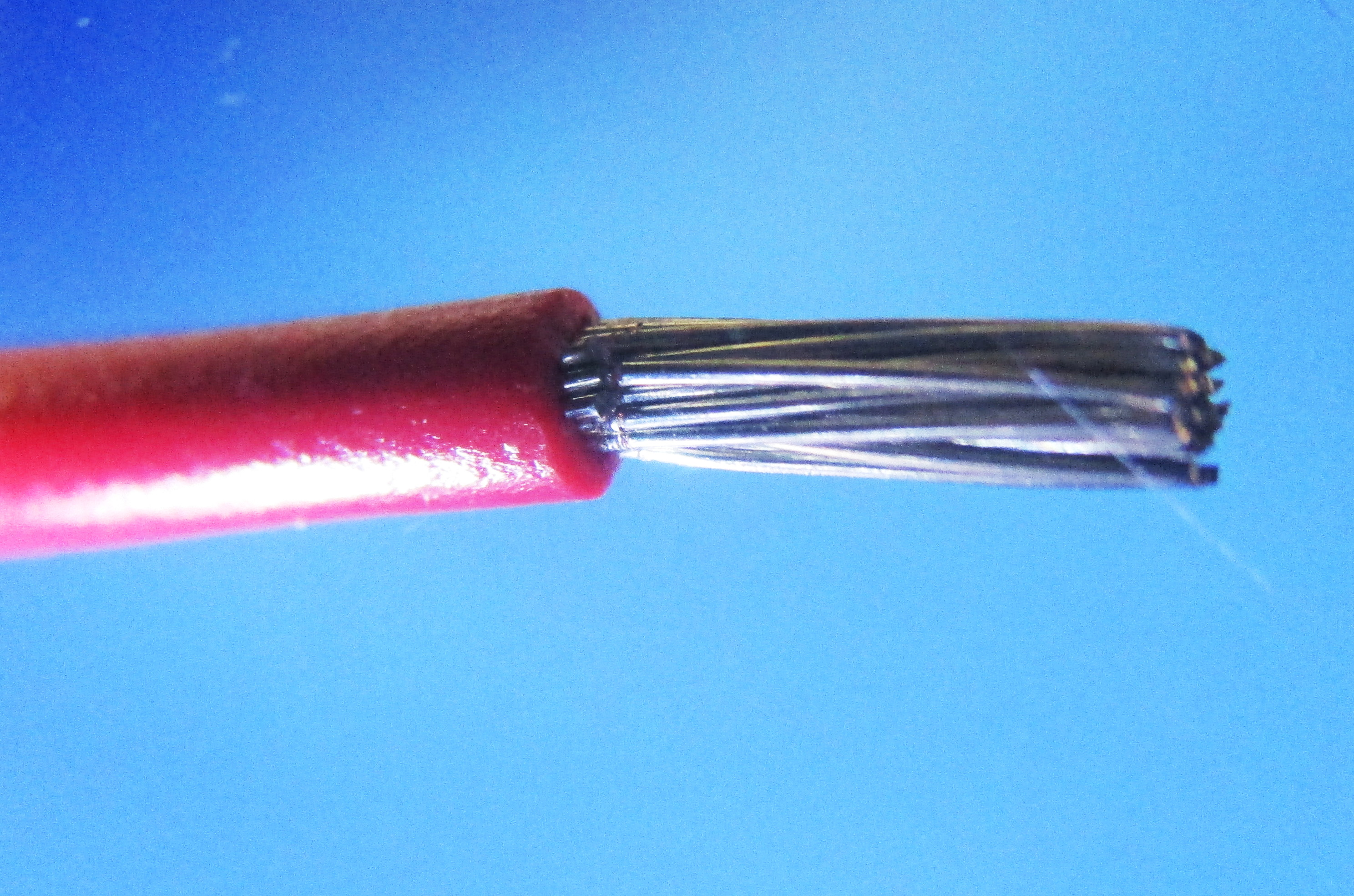
We will also want to look closely at the quality of the strip;
Did the machine succeed at stripping both ends of the wire?
Have any conductors been damaged or cut at the incise point of the strip?
Proceed to troubleshooting in the next step.


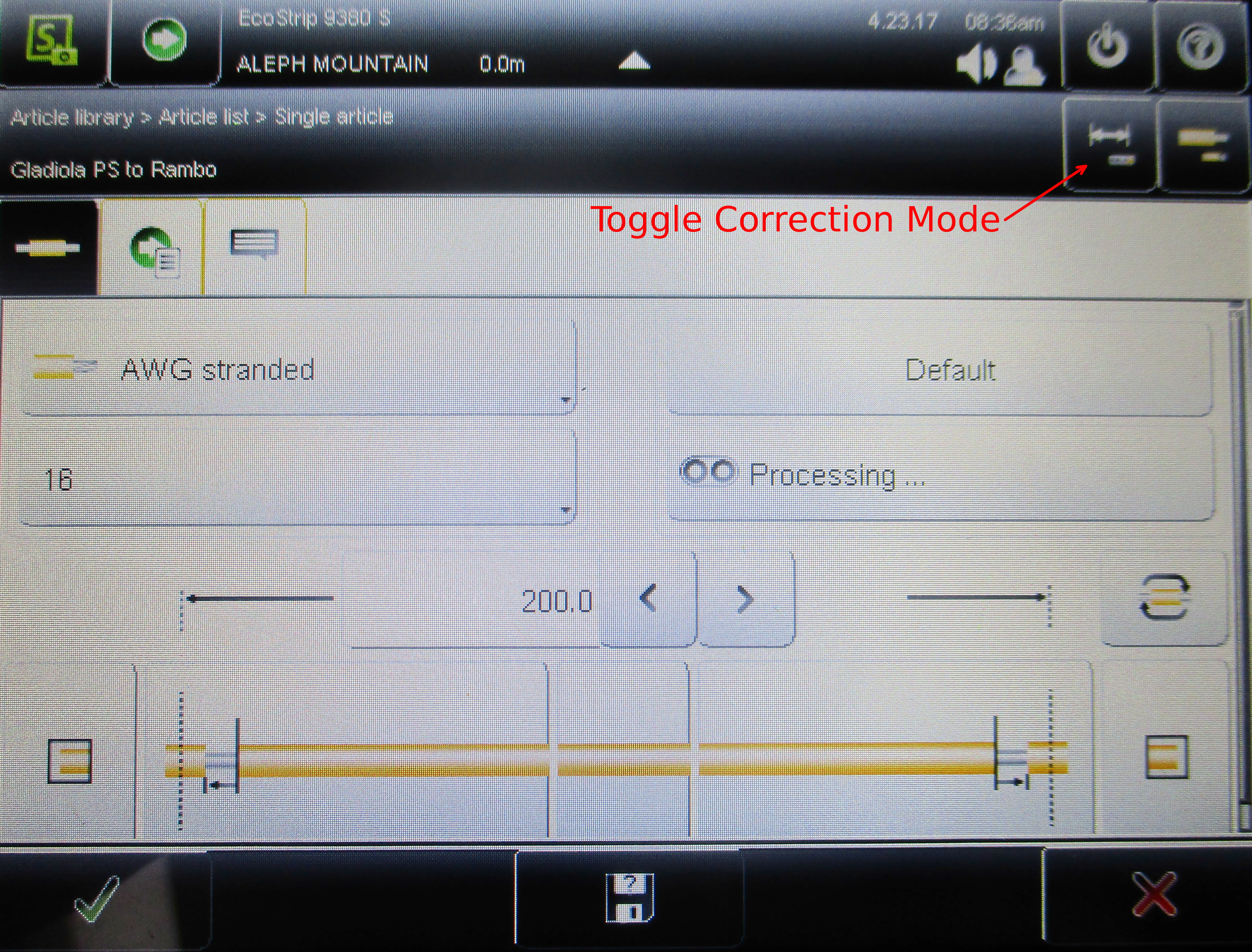
There are two methods for correcting the overall cut length of the article;
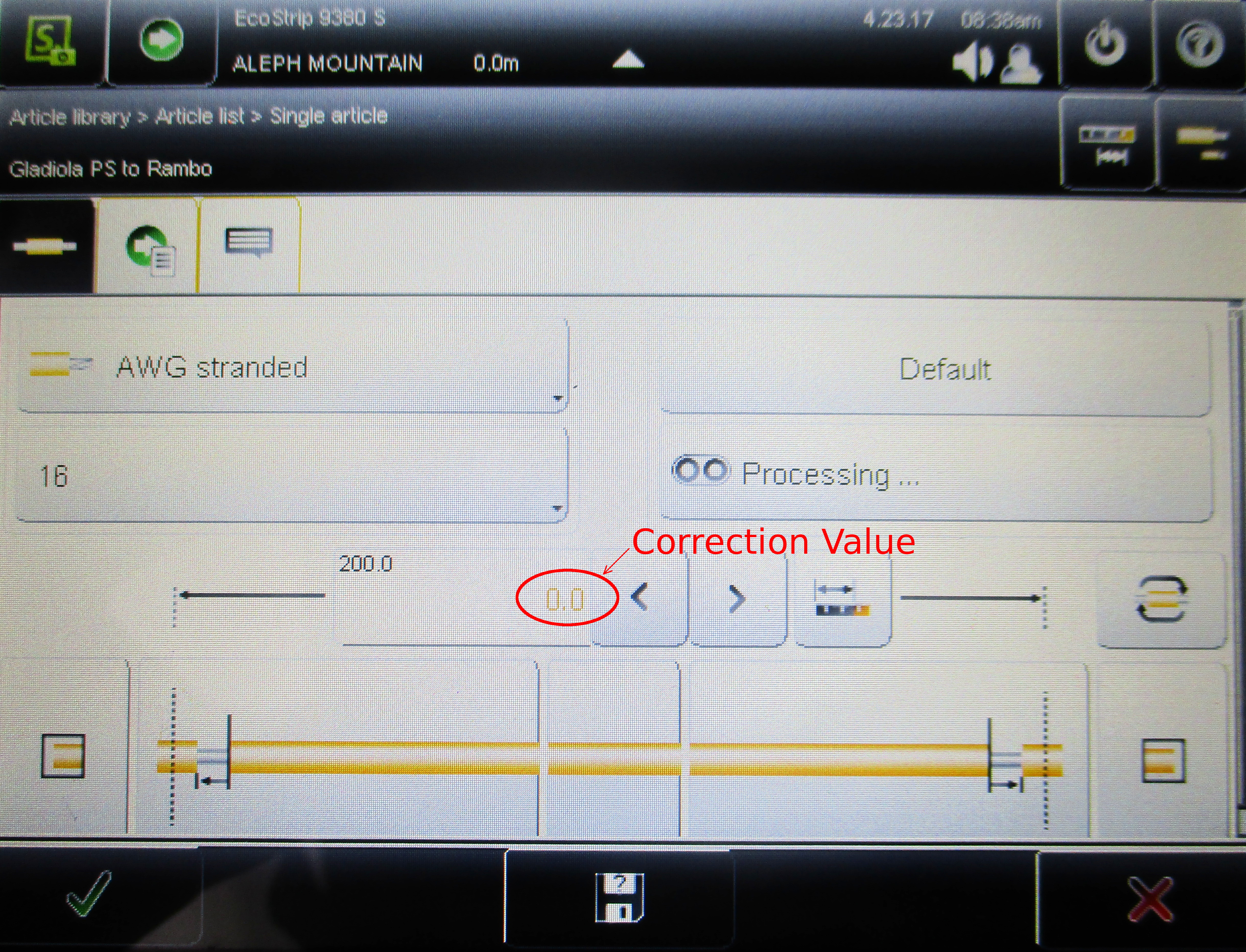
Correction mode – toggled via a button near the top right of the screen above the article properties. Using this mode allows the user to easily add or subtract length from any part of the processed wire including strip and pull-off lengths. When correction mode is activated, the predetermined lengths become smaller font in their respective areas and the correction value is shown in yellow. Simply add or subtract the appropriate amount to produce a sample that meets specifications.
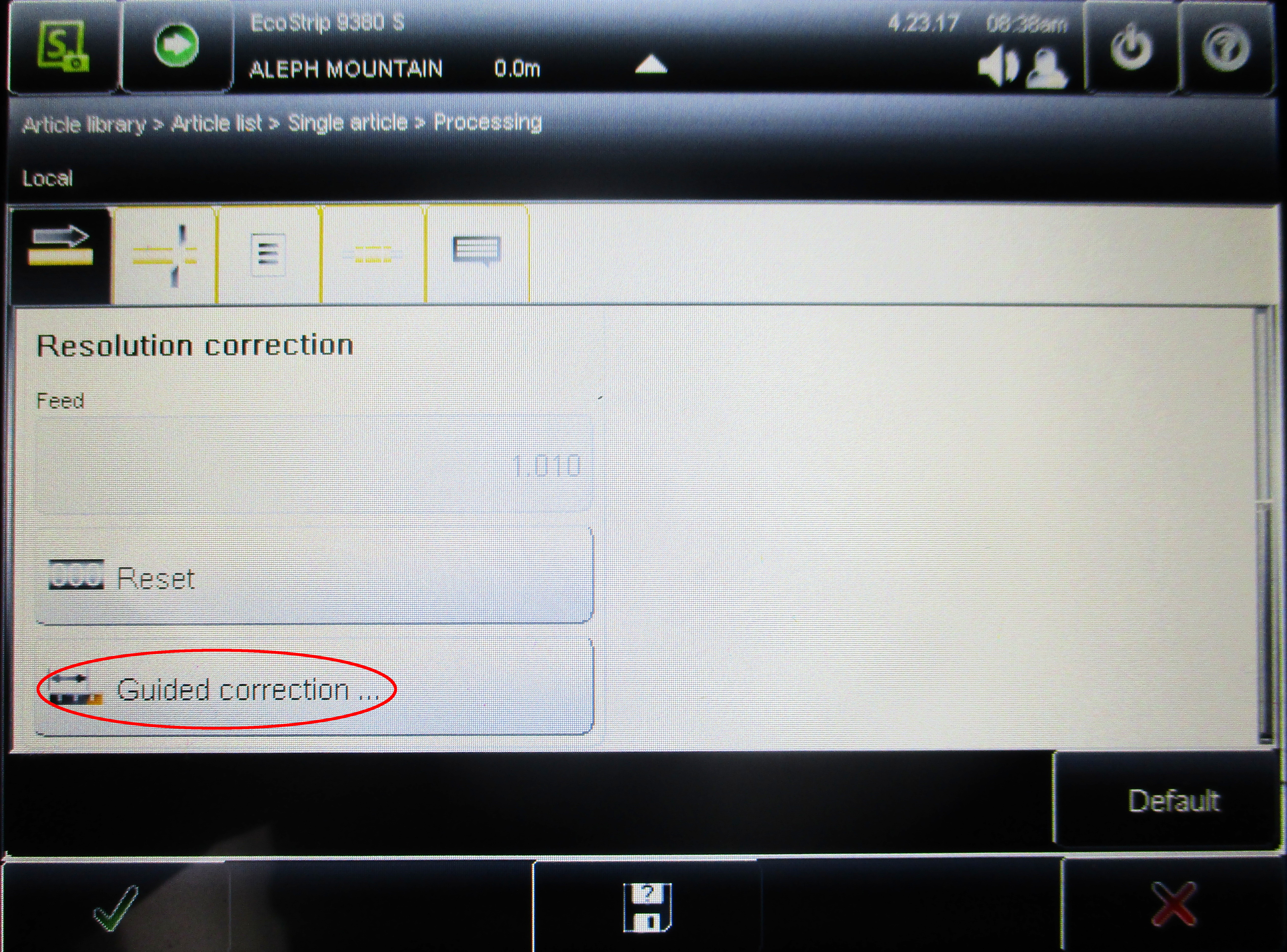
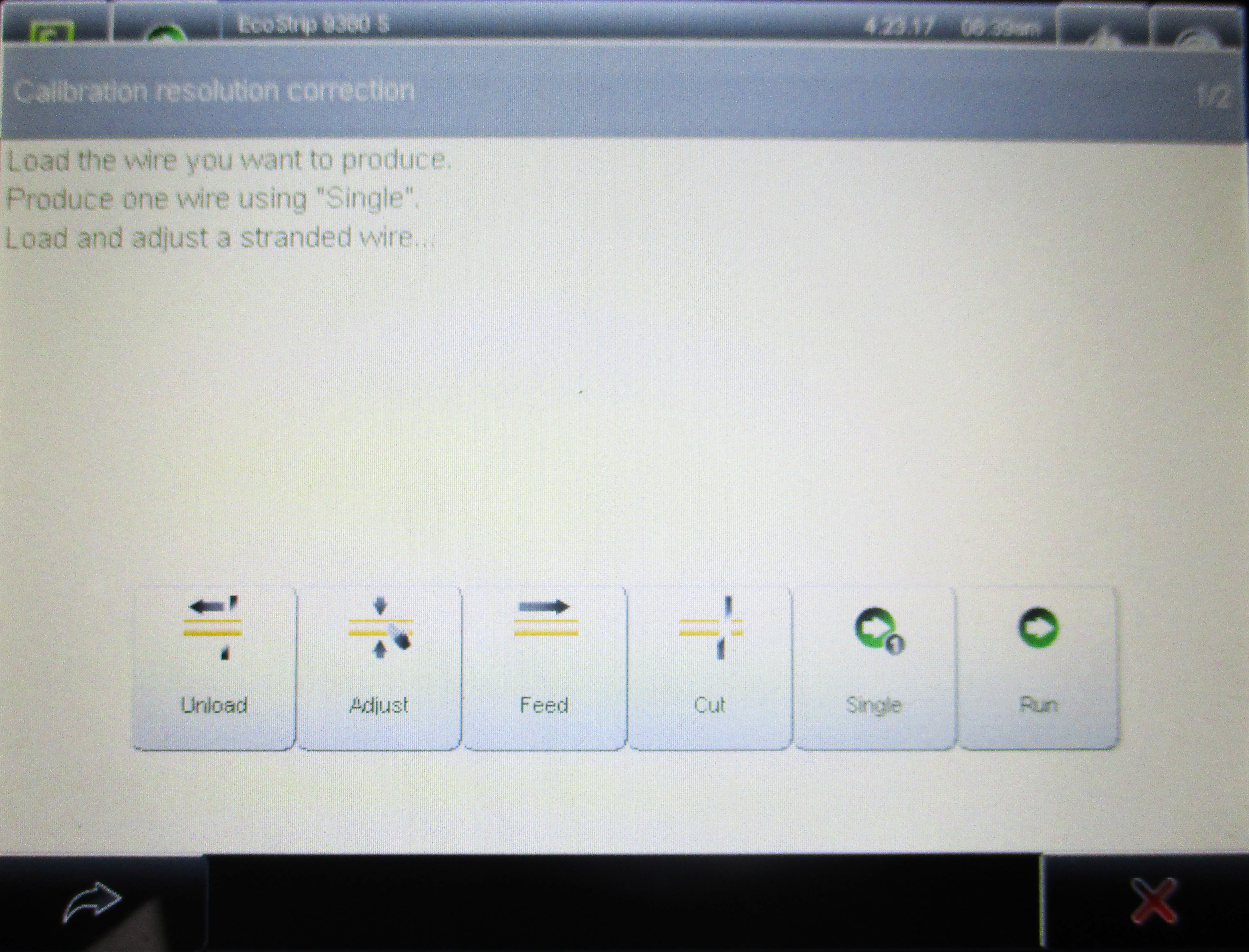
Guided Correction – Guided Correction is found by opening the processing menu, scroll to the bottom and select “Guided Correction.” Production commands will now be visible in the opened dialogue if you don’t already have a measured sample. Tap the arrow in the bottom left corner of the screen once you have your sample. Enter the measured over-all length of your sample into the field provided and tap the check mark in the bottom left corner of the screen. The machine has corrected its feed rate based off the length provided. Produce and measure another sample to verify the correction was successful.
Use Correction Mode as described above if adjustments to strip and pull off lengths are required.

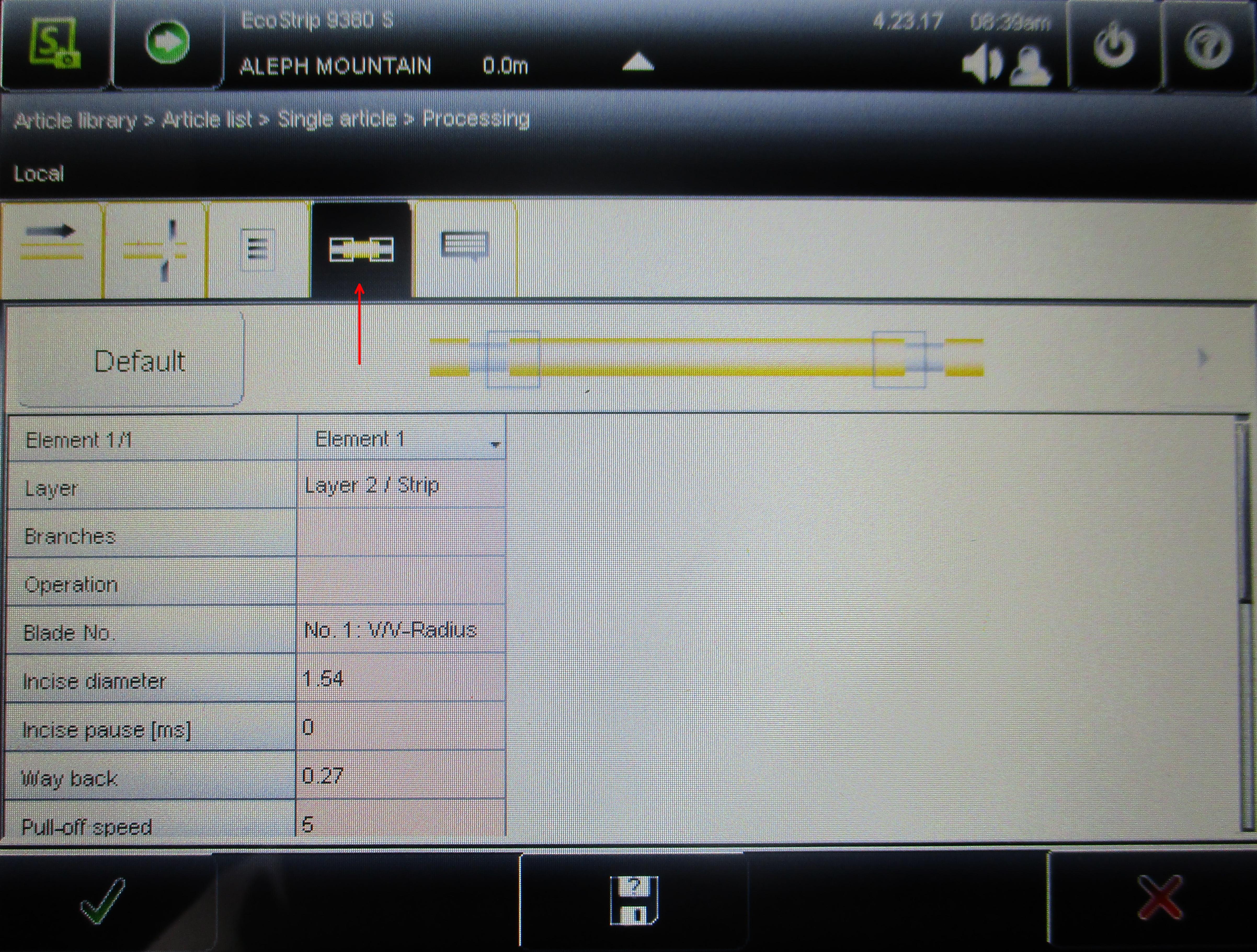
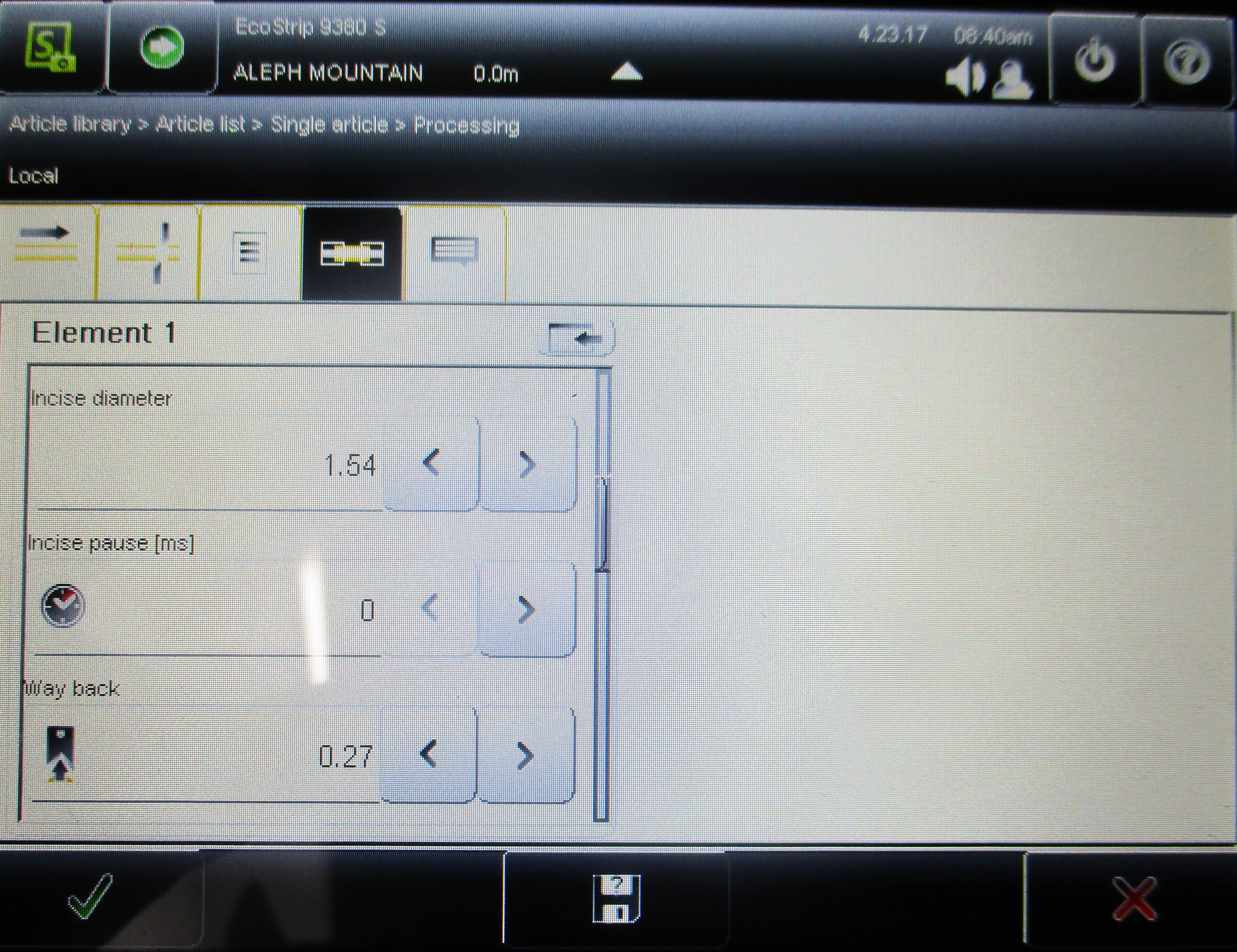
If the machine failed to strip the wire as specified on either end, verify your settings are correct and adjust if necessary. Sometimes a slight increase of the pull-off length on the troublesome side can be helpful. If the cuts are not being made deep enough to strip the wire, the “Incise Diameter” value can be adjusted in the Processing Menu’s fourth tab. Decrease the Incise Diameter until a sample can be reliably produced with both ends stripped as desired.
Looking closely at the point where the cut was made for stripping the wire end; Do any conductors appear cut or damaged?
If any conductors are cut or damaged, the cut is being made too deep, or the blades are not retracting far enough before pulling back the insulation. Both issues can be corrected in the Processing Menu’s fourth tab. Tap the table presented to adjust the values.
Increase the “Incise Diameter” value if cuts are made too deep.
The “Way Back” value is the retraction of the blades from the incise position just far enough so that the blades grip the insulation but do not contact the conductors during pull-off.
When cutting the shielded multi-conductor cables (Grey 4-conduit) users often see torn foil near the incise point. Increasing the Way Back value will help alleviate this issue.

Once proper settings have been verified you may continue producing in batches of 50, as needed. Batch quantities are set on the second tab of Single Article View. Then, simply hit "Run" in the Production Commands Menu.
Continue to check individual processed wires throughout the batch as well as at the end of each batch.
Once a batch has been completed, bind the batch of wires together with blue painters tape. On the blue painters tape, write your initials and the length and harness name of the wires cut.
Continue processing all needed cuts from the loaded raw material before selecting the next raw material to be cut.