Open HardwareAssembly Instructions
Guides for installation and assembly of the LulzBot line of products made by FAME 3D LLC.
Guides for installation and assembly of the LulzBot line of products made by FAME 3D LLC.
1x- [AS-CB0039] V3 Dual Extruder Harness 1
1x- [AS-CB0042] V3 Dual Extruder Harness 0
1x- [AS-HE0023] E3D Dual V3 Hot End, Left
1x- [AS-HE0024] E3D Dual V3 Hot End, Right
2x- [AS-TH0067] V3 Thumbscrew Assembly
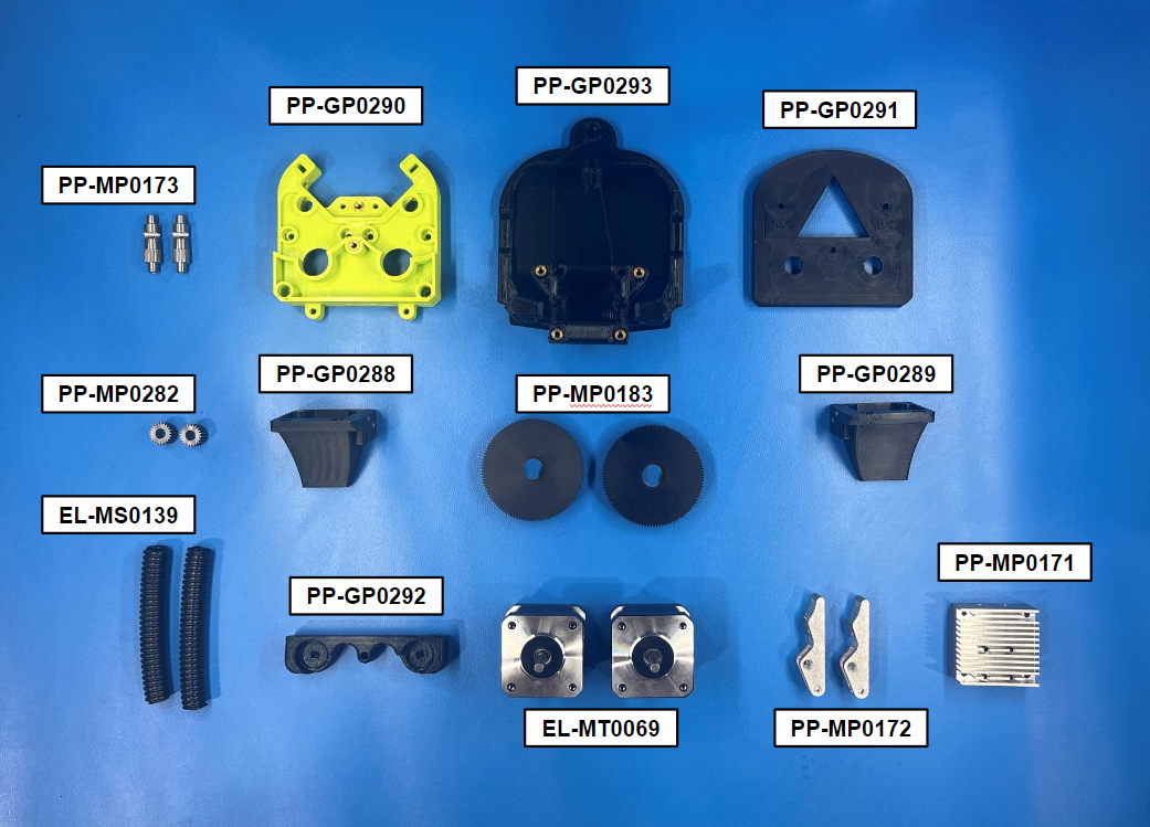
2x- [EL-MS0139] Tubing Corrugated Loom 3/8"
2x- [EL-MT0069] NEMA 17 Half Height Stepper Motor
1x- [EL-SW0022] Switch Basic SPDT 3A
6x- [HD-BT0012] M3 Set Screw
10x- [HD-BT0039] M3x12 SHCS, Black-Oxide
1x- [HD-BT0042] M3x30 SHCS, Black-Oxide
3x- [HD-BT0043] M3x35 SHCS, Black-Oxide
2x- [HD-BT0049] M5x14 SHCS, Black-Oxide
1x- [HD-BT0104] M3x8 BHCS, SST
2x- [HD-BT0107] M2x10 SHCS, Black-Oxide
4x- [HD-BT0116] M3x10 FHCS, Black-Oxide
2x- [HD-BT0154] M3x45 SHCS, Black-Oxide
3x- [HD-BT0185] M3x16 SHCS, Black-Oxide
2x- [HD-BT0203] M3x60 SHCS, Black-Oxide
4x- [HD-MS0058] Wire Tie 8" Black
2x- [HD-MS0375] ESD Foam 1.06"x.6"x.3" Extruder Pin Insertion
8x- [HD-MS0411] Premium Two Side Rubber Sealed Bearing
2x- [HD-MS0421] Music-Wire Steel Precision Compression Spring Zinc
2x- [HD-MS0555] LCD Spacer 4.5OD
2x- [HD-NT0001] M3 Locknut
2x- [HD-NT0004] M3 Nut
2x- [HD-WA0012] M2 Washer
1x- [HD-WA0035] M3 Lock Washer
11x- [HD-WA0038] M3 Washer
2x- [HD-WA0040] M5 Washer
4x- [HD-WA0047] Spring Steel Shim for Screw Shoulders Shortening
1x- [PP-GP0288] Dual Duct Left V3
1x- [PP-GP0289] Dual Duct Right V3
1x- [PP-GP0290] Dual Extruder Body V3
1x- [PP-GP0291] Bearing Housing Front V3
1x- [PP-GP0292] Bearing Housing Rear V3
1x- [PP-GP0293] Dual Mount V3
2x- [PP-GP0501] Dual V3 Fan M3x3 Spacer
1x- [PP-MP0162] Thermal Compound E3D Hotend
1x- [PP-MP0171] Dual V3 Heat Sink
2x- [PP-MP0172] Aluminum Idler for Dual V3
2x- [PP-MP0173] Knurled Gear Shaft for Dual V3
2x- [PP-MP0183] 108 Tooth 20pa 0.5 Mod Delrin Gear
2x- [PP-MP0282] E3D V3 Aero Steel Pinion Gear

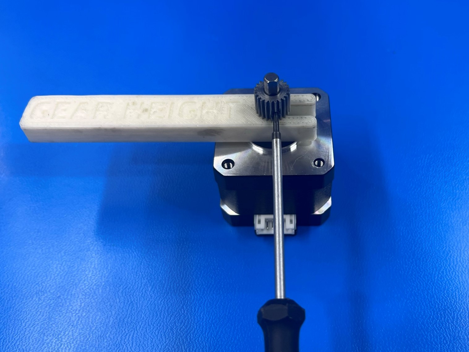
Use the printed spacer jig to offset the E3D steel pinion gear [PP-MP0282] to the NEMA 17 half height stepper motor [EL-MT0069]. Make sure the set screw is aligned with the flat side of the motor shaft and its on the bottom side.
Then repeat for the second stepper motor.
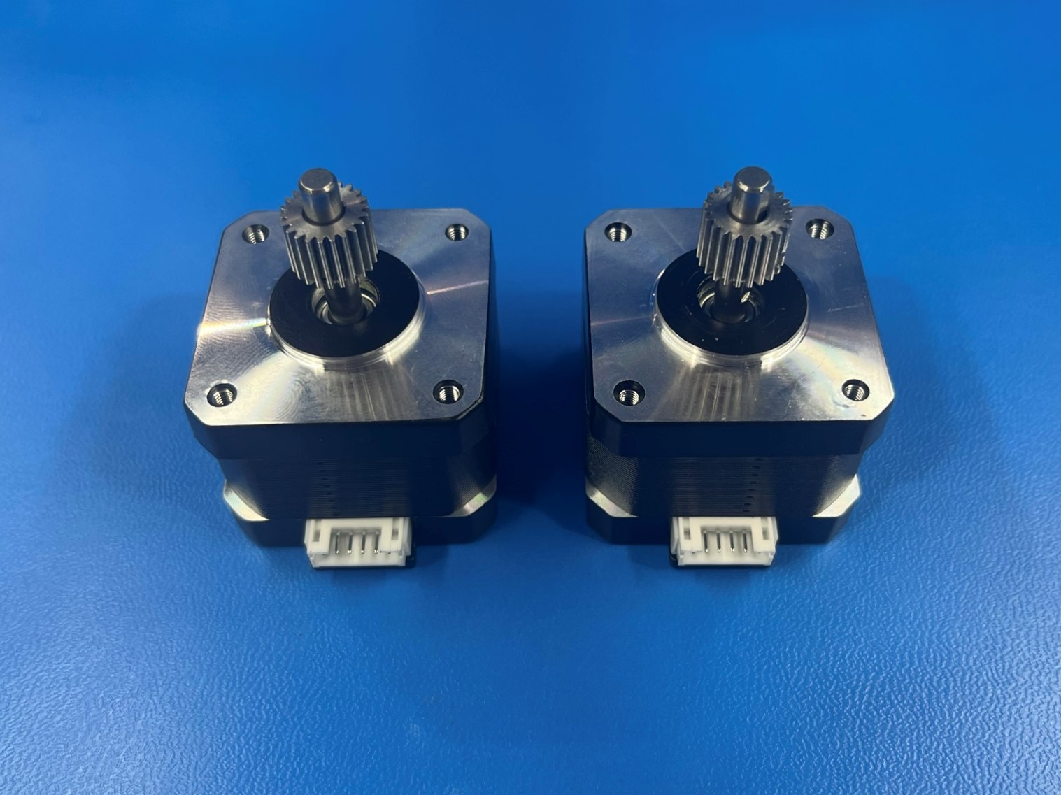
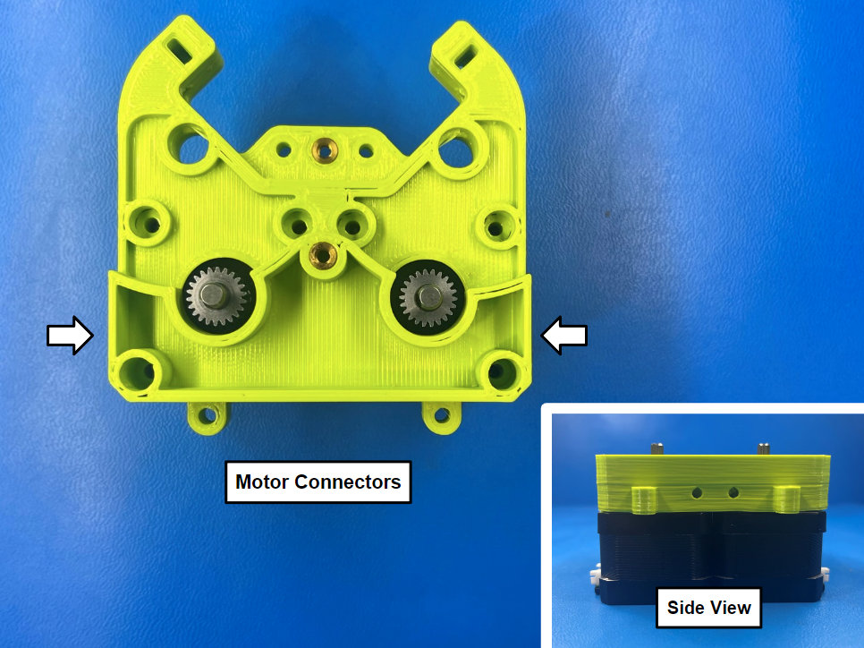
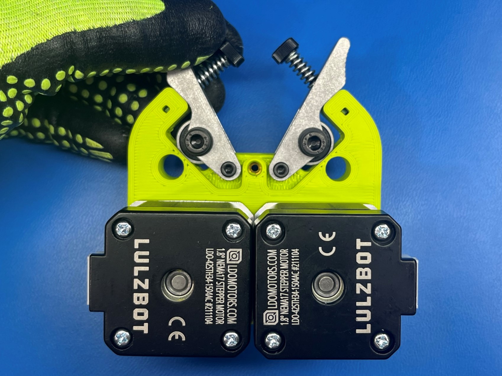
Align the motors with the dual extruder body [PP-GP0290] make sure the connectors are on the sides of the extruder body.
Once the motors are aligned, attach the motors to the extruder body using 3x M3x12 [HD-BT0039]. Then repeat for the other side.
Place 2x M3 nuts [HD-NT0004] inside the extruder body in the rectangular holes at the ends of the part.
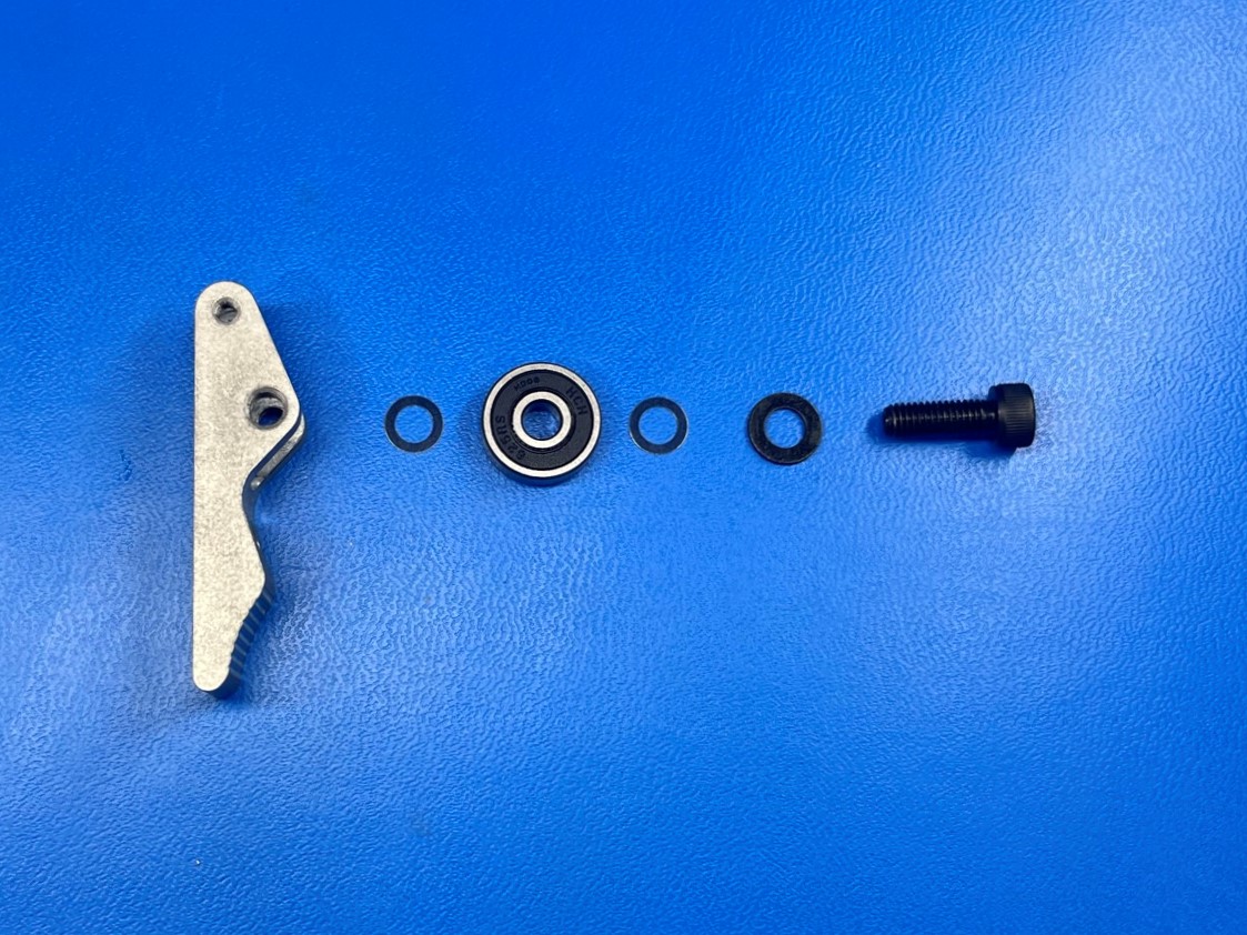
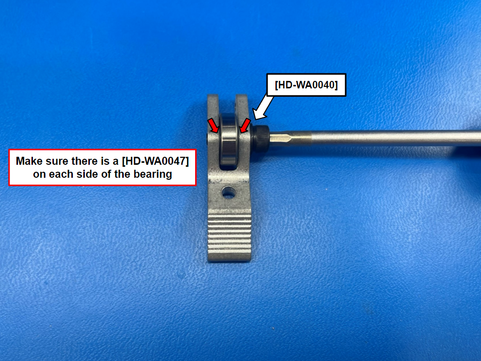
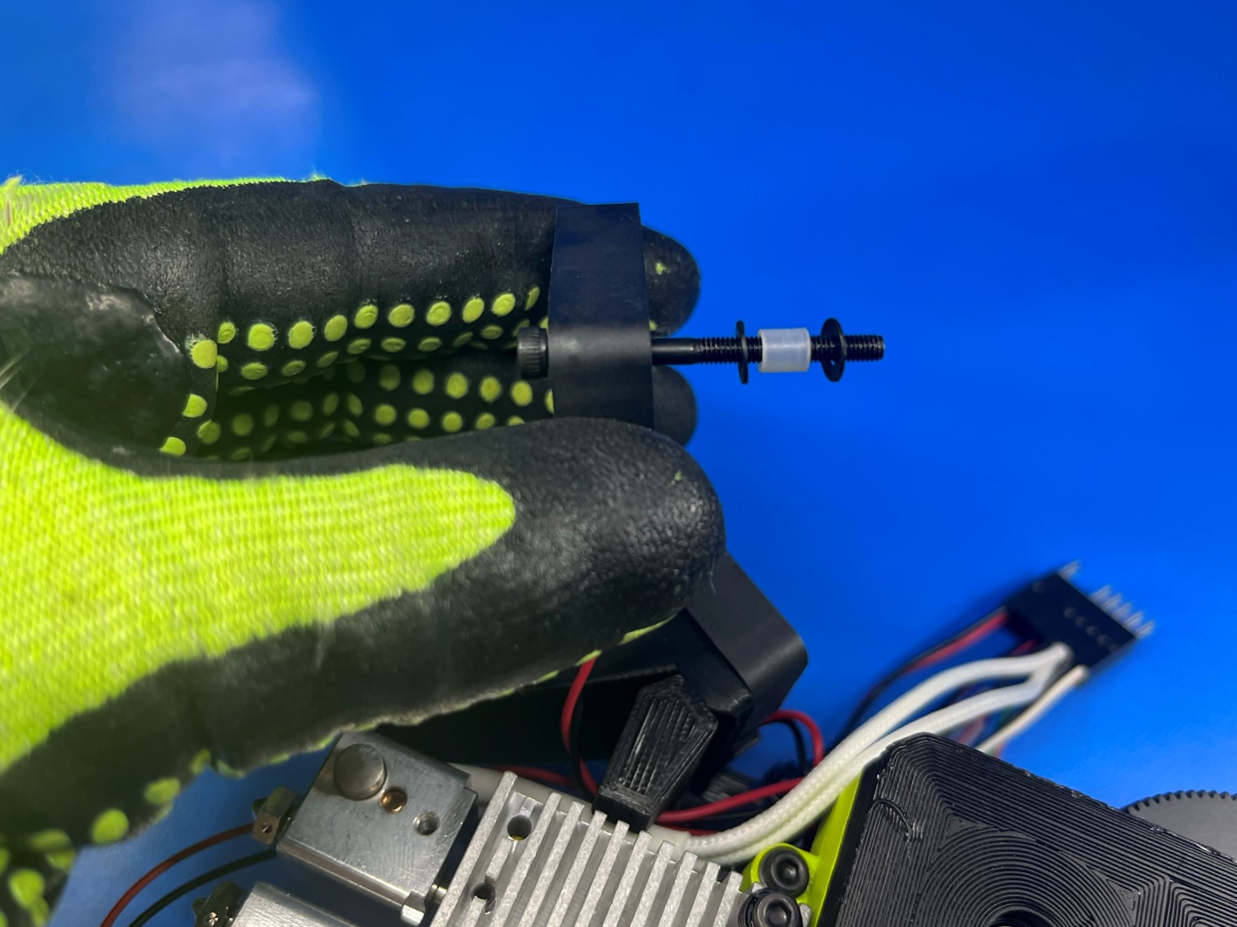
Then assemble the aluminum idler [PP-MP0172] with 1x M5x14 SHCS [HD-BT0049], 1x rubber sealed bearing [HD-MS0411], 1x M5 washer [HD-WA0040] and 2x spring steel shim [HD-WA0047].
Slide the M5 washer over the M5x14 SHCS and then start to thread the bolt through the aluminum idler. Now place a spring steel shim on both sides of the rubber sealed bearing and thread the screw through them.
Keep tightening the screw until it stops and the bolt is completely through the idler.
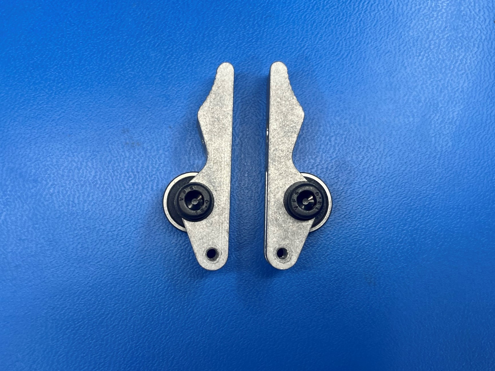
Then repeat steps so that you have 2 assembled idlers. Make sure to mirror the assembly
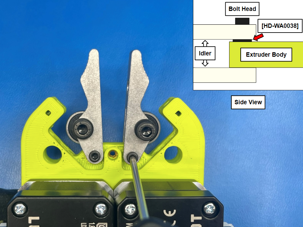
Now attach the idler to the extruder body using 1x M3x12 SHCS [HD-BT0039] and 1x M3 washer [HD-WA0038] between the idler and extruder body. Make sure bolt heads are on the same side as the bottom of the motors.
Then repeat for the other side.
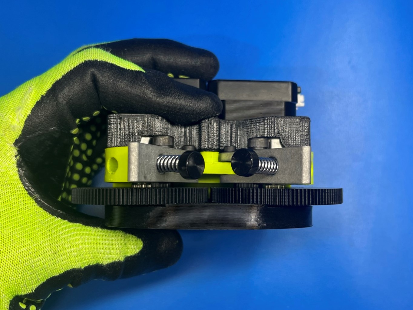
Finally secure the top side of the idler to the extruder body using 1x V3 thumbscrew assembly [AS-TH0067] with 1x steel precision compression spring [HD-MS0421]. Slide the spring around the thumbscrew assembly then secure the top of the idler to the extruder body.
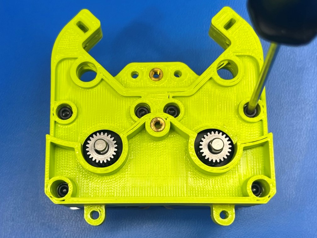
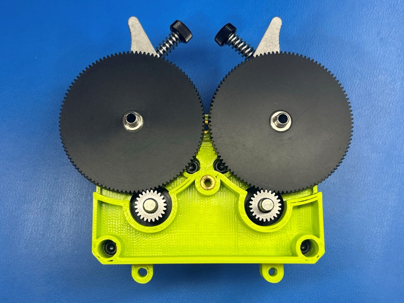
Place the 108 tooth delrin gear, with the knurled gear shaft pressed inside of it, on the extruder body with longer side of the sliver shaft by the bearing on the idler and the gear meshing with the motor gear.
Then repeat for the other side.
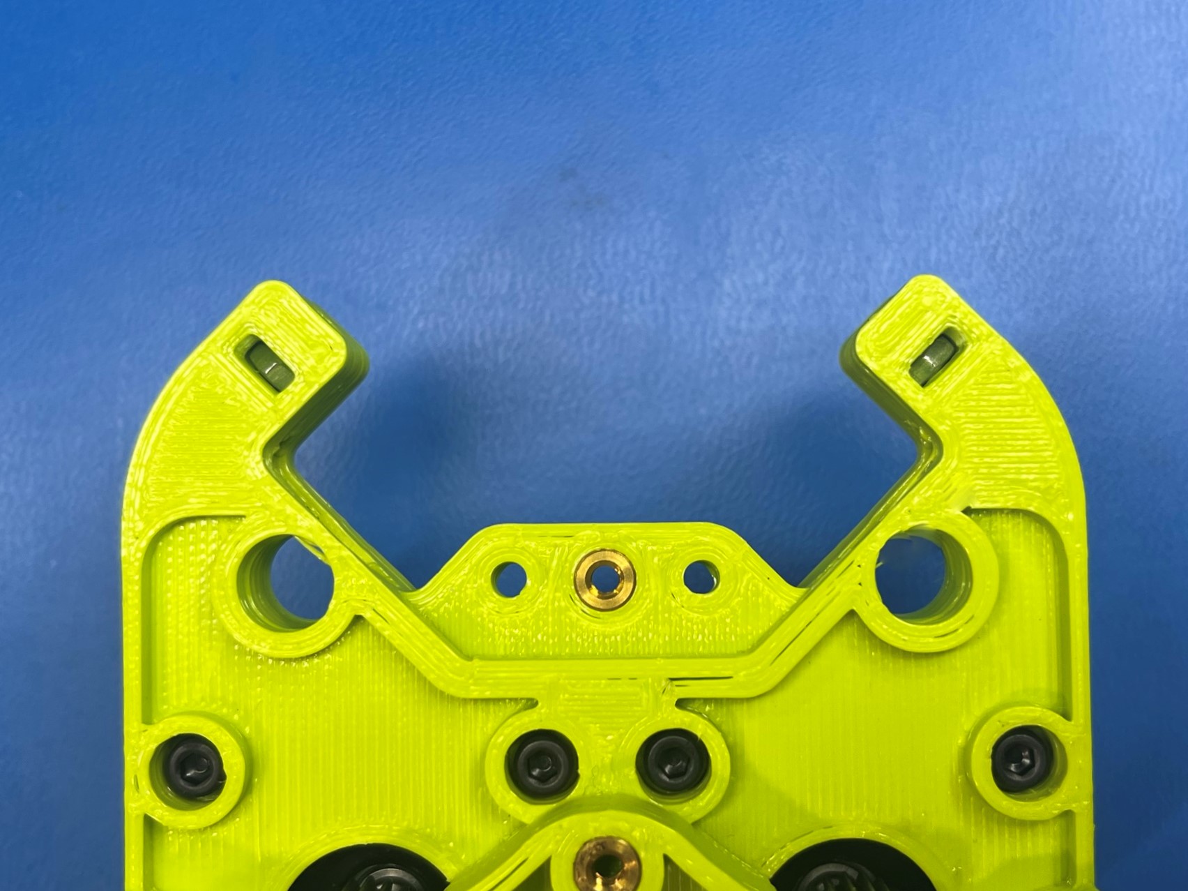
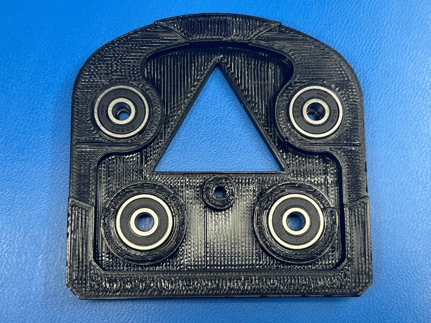
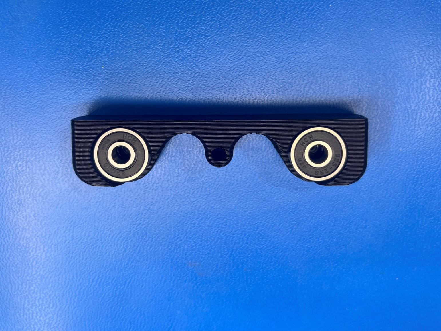
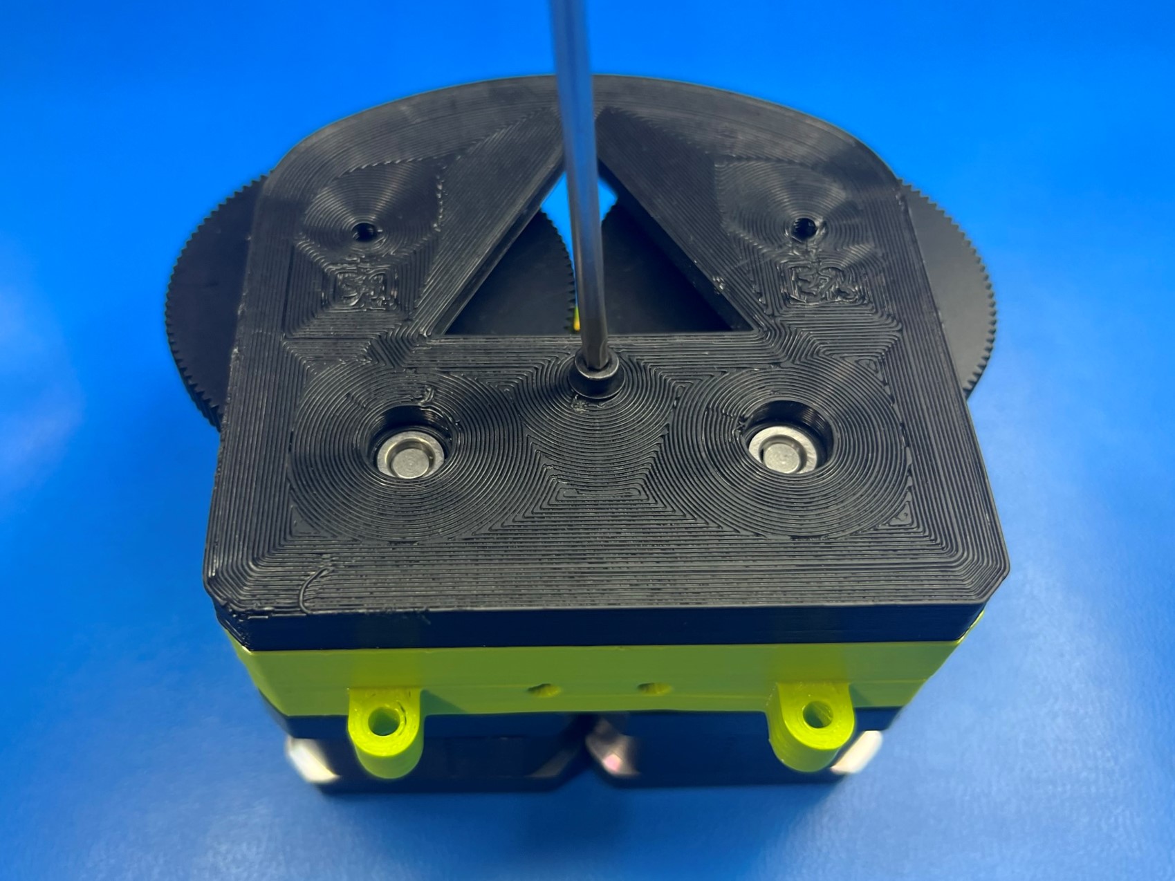
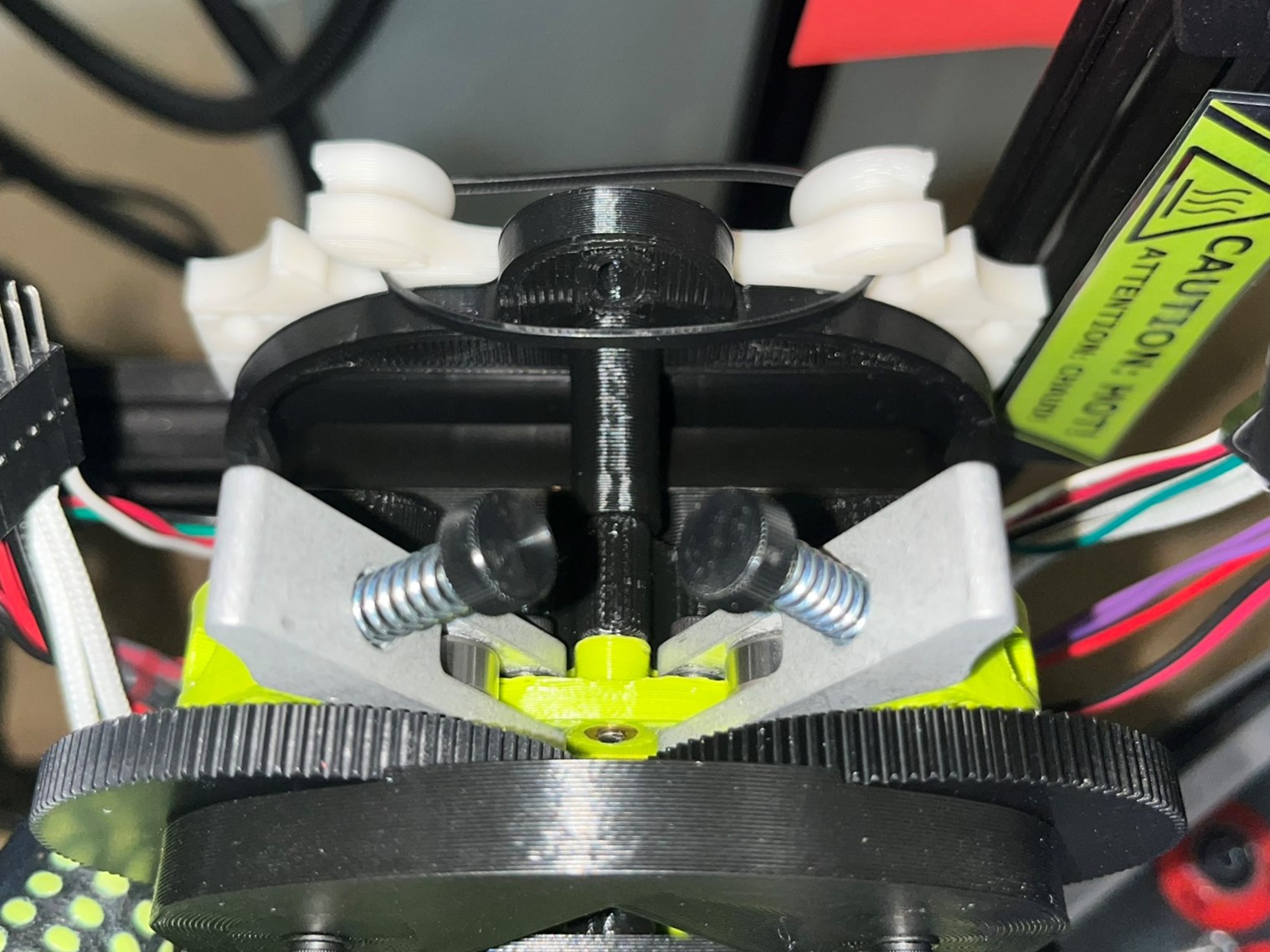
Press 4x rubber sealed bearings [HD-MS0411] into the bearing housing front [PP-GP0291] and press 2x rubber sealed bearings into the bearing housing rear [PP-GP0292]. Then flip the bearing housing rear over and place 2x M3 locknut [HD-NT0001] inside the nut traps.
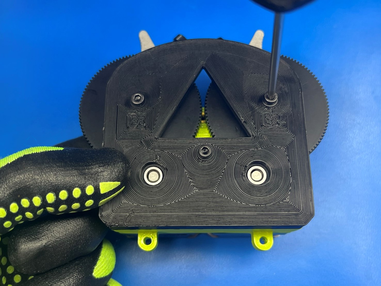
Place the bearing housing front over the gears making sure the bearings are aligned with the gear shafts. Secure the bearing housing front using 1x M3x16 SHCS [HD-BT0185] with a M3 washer [HD-WA0038].
Then align the bearing housing rear with the bottom side of the gear shafts and secure using 2x M3x45 SHCS [HD-BT0154] with M3 washers.

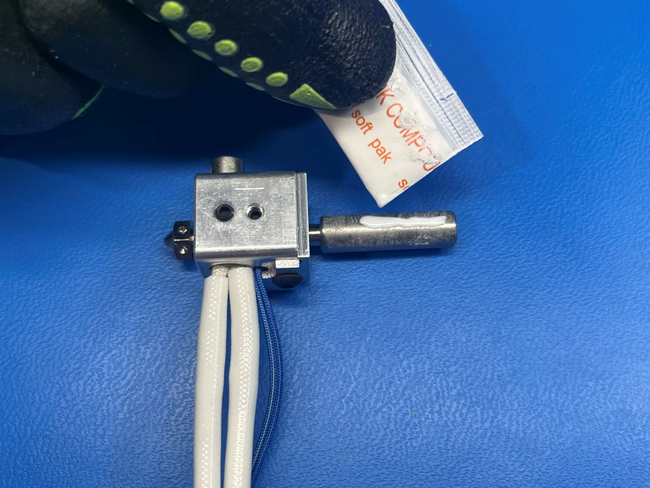
Cut open the thermal compound [PP-MP0162] and apply the compound to either the left or right E3D dual hot end [AS-HE0023] or [AS-HE0024].
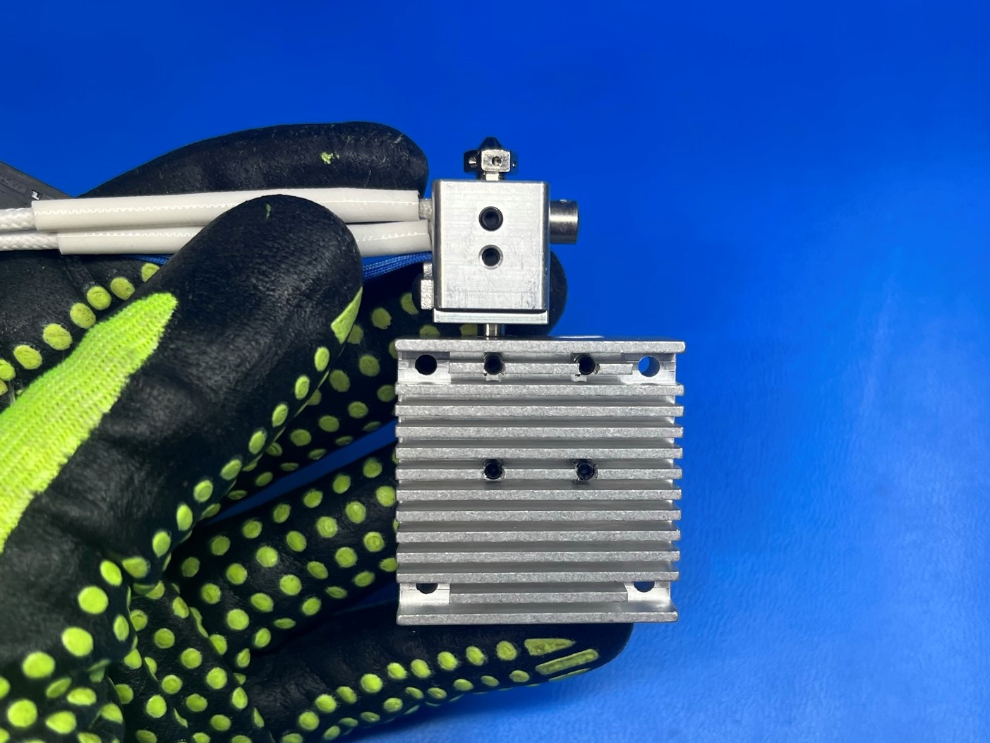
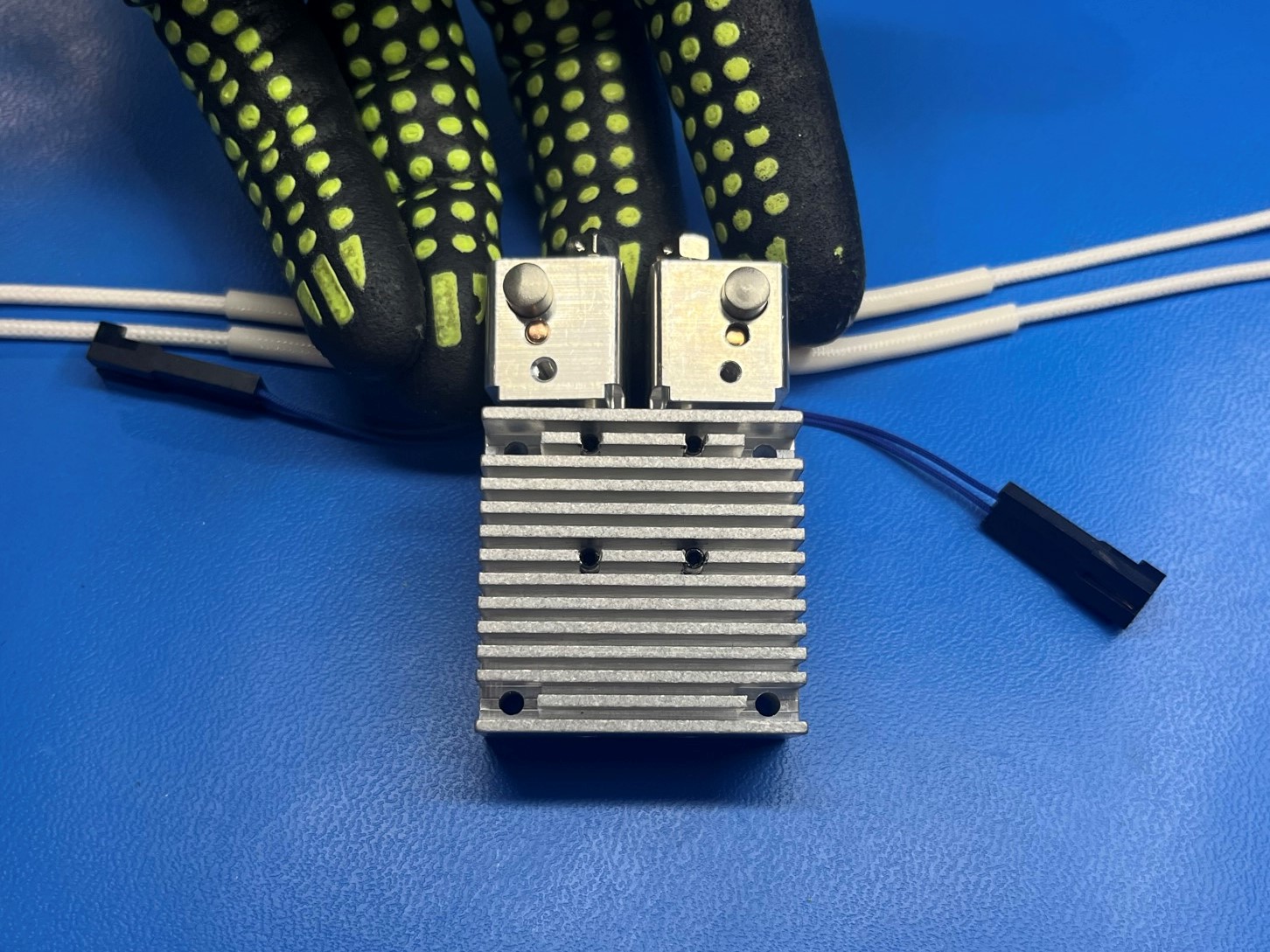
Once the compound is applied to the hot end slide it into the dual head sink [PP-MP0171] making sure its on the side with the four holes. Then spin the hot end to spread the thermal compound. Once the compound is spread out rotate it so that the wire are on the same side as the flat side of the dual heat sink.
Repeat the process for the other hot end, but you will have to try to spread the compound with the packet since you won't be able to rotate the hot end inside the heat sink.
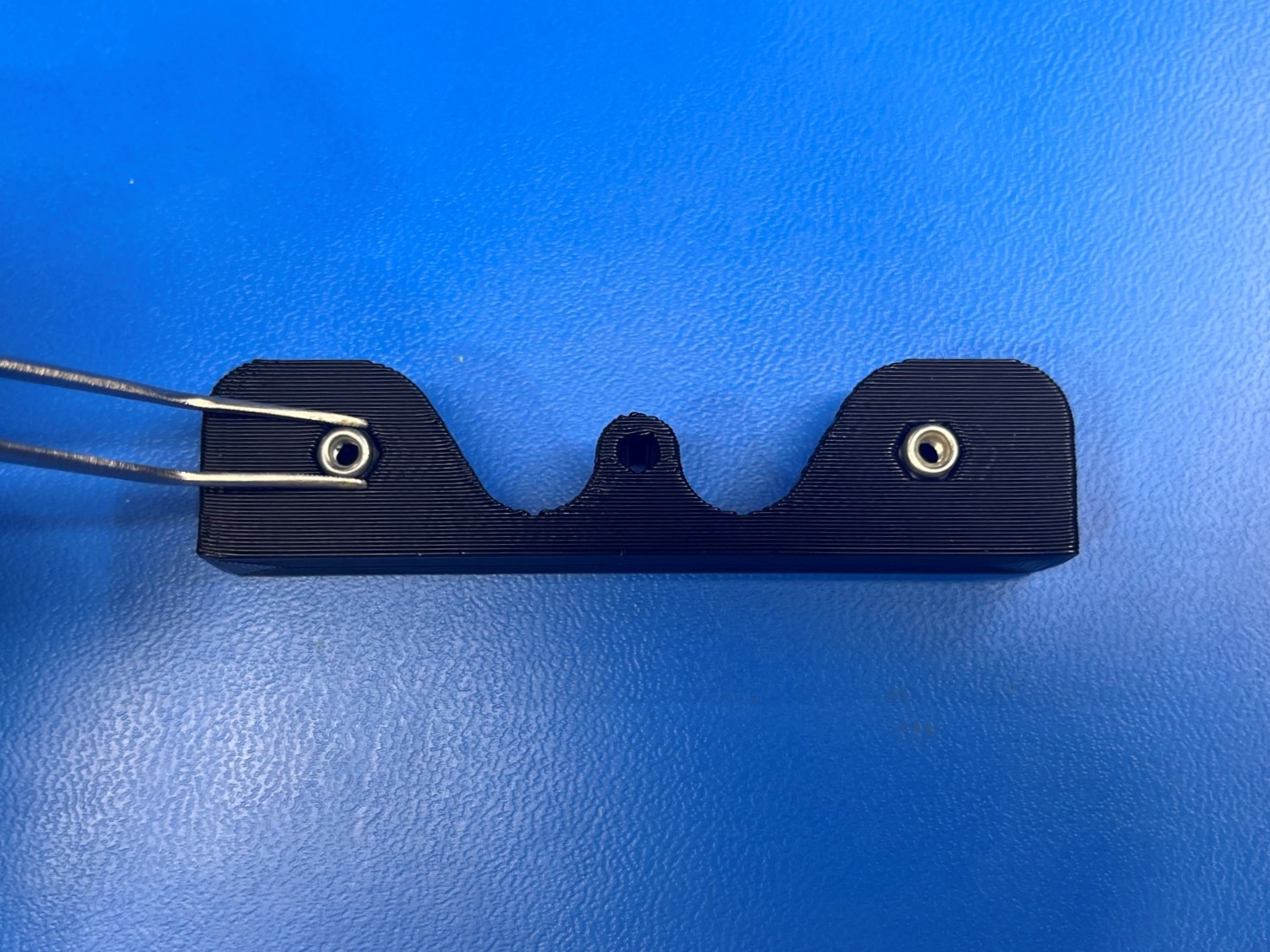
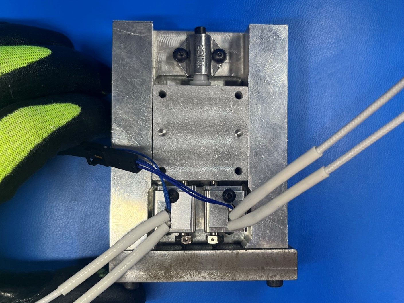
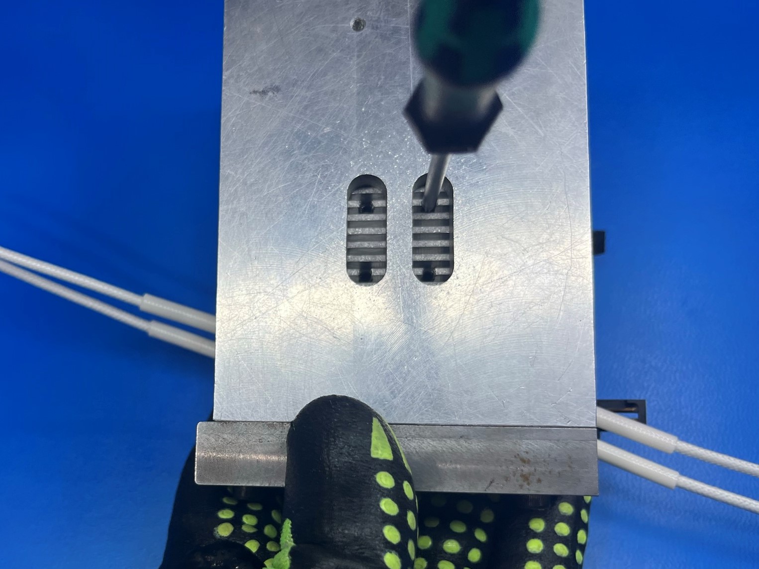
The place the dual heat sink with hot ends inside the heat sink jig making sure the flat side is facing up. Then while holding the heat sink in place flip the jig over so that the bottom side of the jig is facing up.
Tighten the four set screws that are threaded into the heat sink. If the heat sink doesn't have the set screw inside it already use 4x M3 set screws [HD-BT0012].


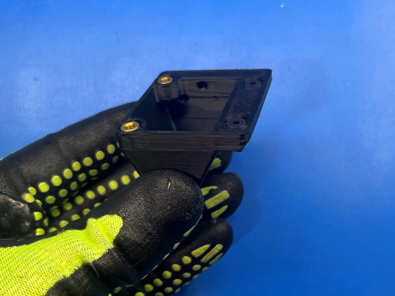
Place the dual mount [PP-GP0293] on the table and set the assembly inside the dual mount. Make sure the two tabs on the dual extruder body are aligned with the two brass inserts on the dual mount.
Then use 2x M3x12 SHCS [HD-BT0039] with M3 washers [HD-WA0038] and secure the assembly to the dual mount.
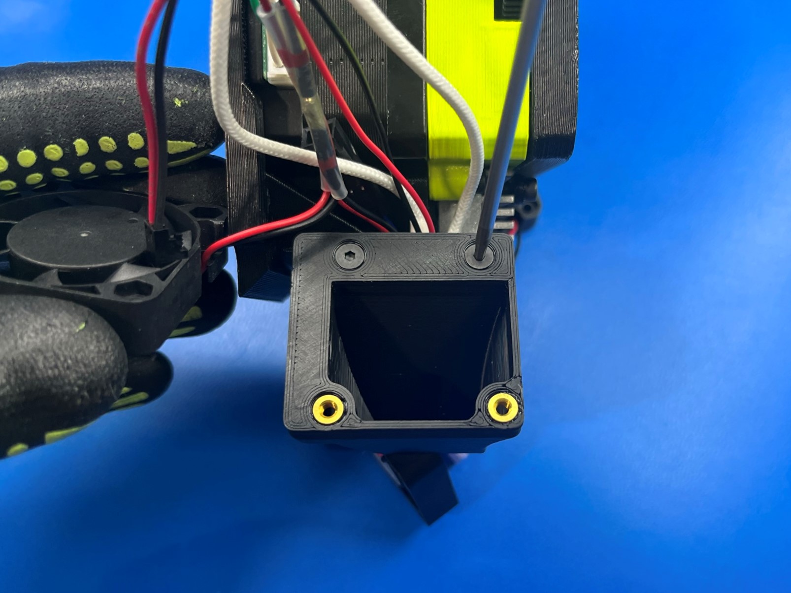
Then take 2x M3 set screw [HD-BT0012] and thread them into the two center holes on the dual mount.
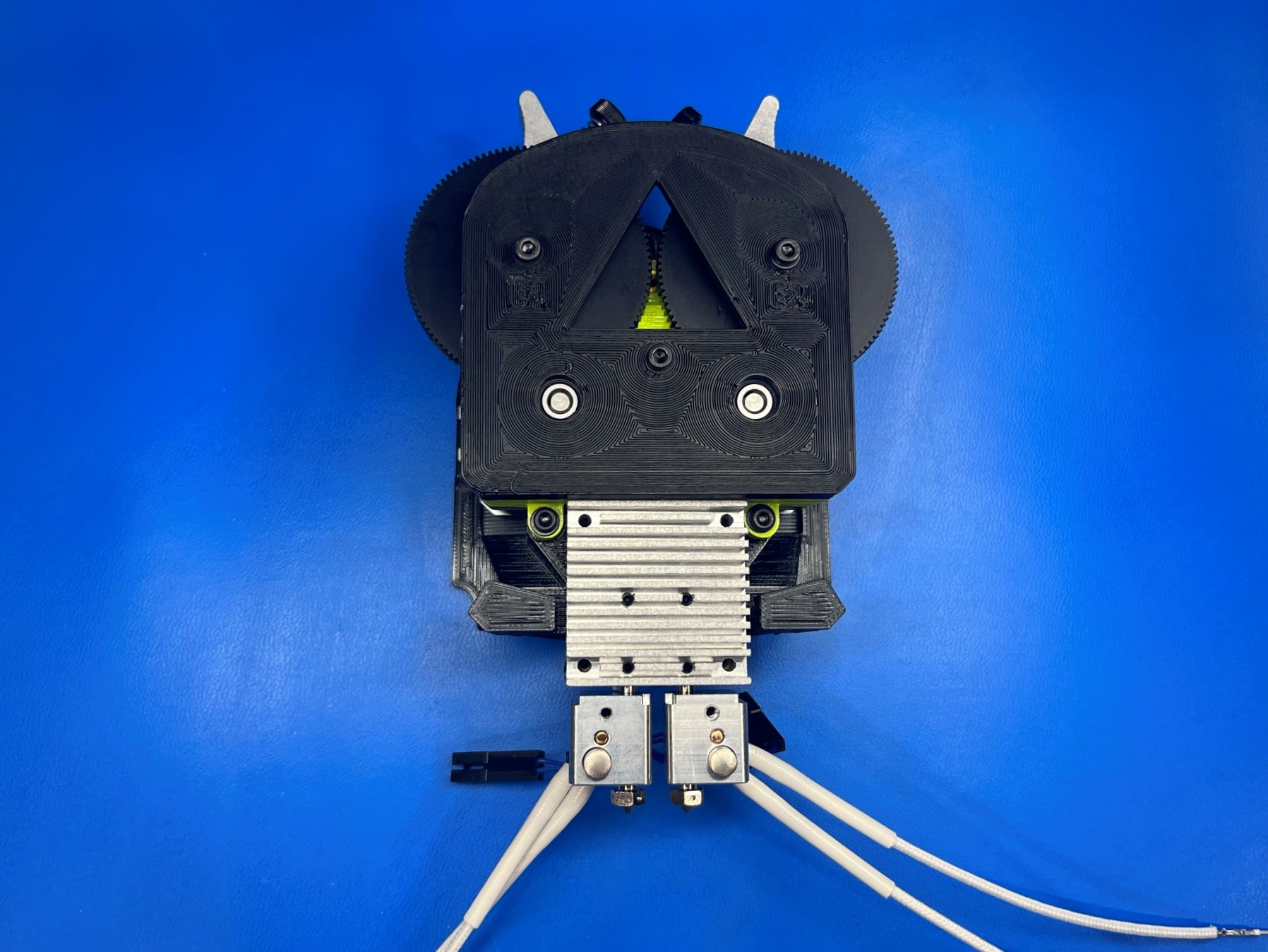
Now place the heat sink over the two set screw making sure the nozzles are facing away from the assembly.
Once the heat sink is in place use 2x M3x60 SHCS [HD-BT0203] with dual fan spacers [PP-GP0501] to attach the heat sink to the dual mount. Make sure not to over tighten these screw the end of the screws should not pass the backside of the dual mount.
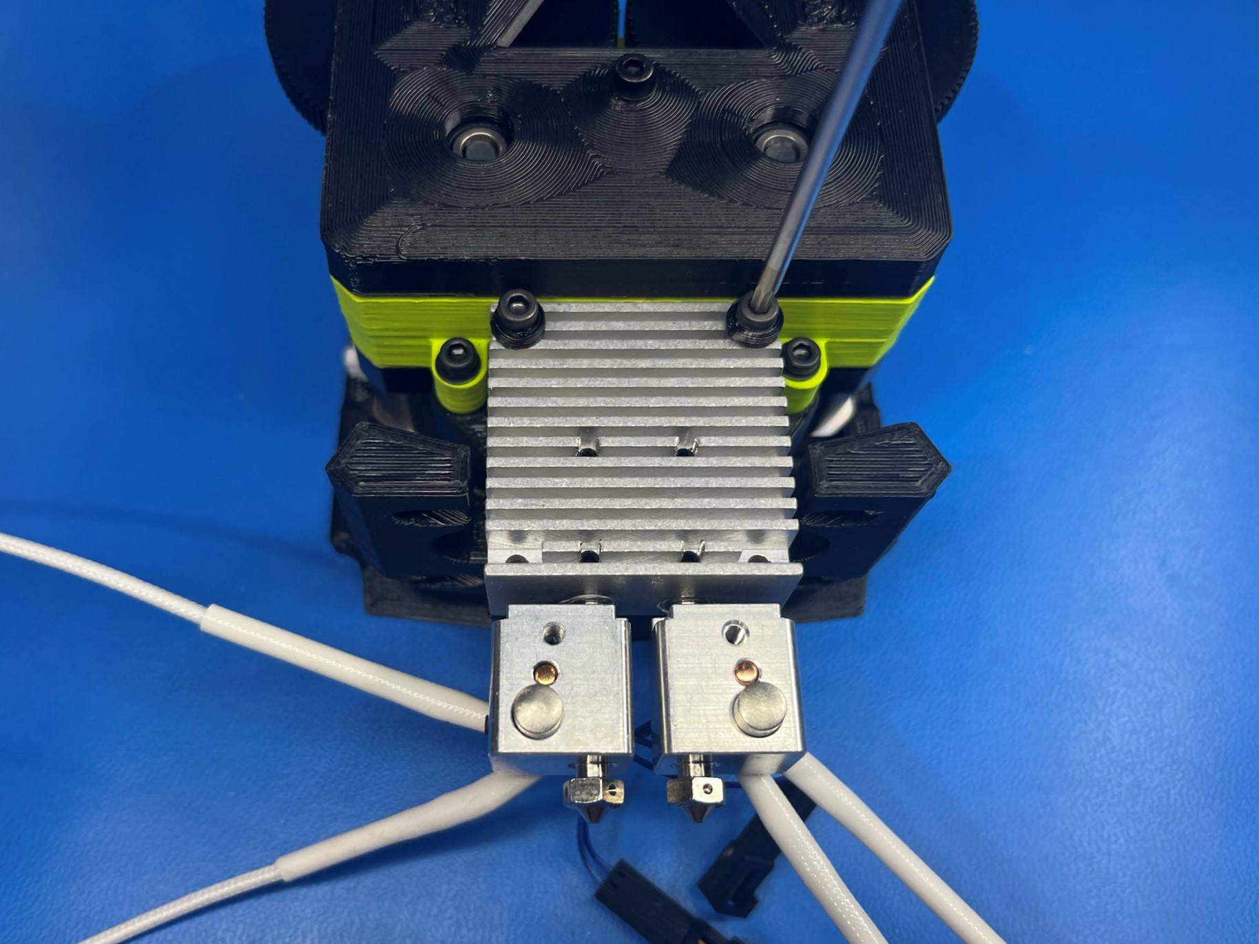
Then take the thermistor wire and the heat cartridge wires and route them through the gap between the heat sink and the dual mount. Make sure they are tucked behind the fan mount.
Repeat for the other hot end.
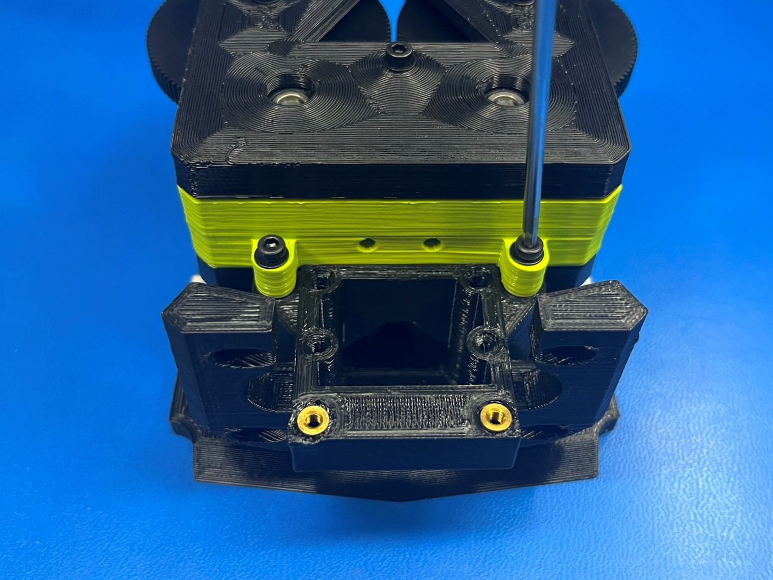
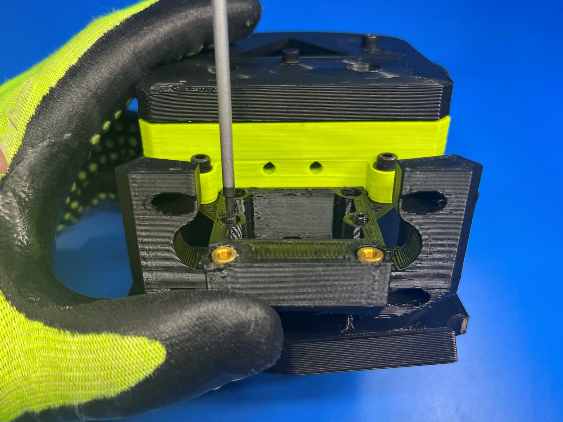
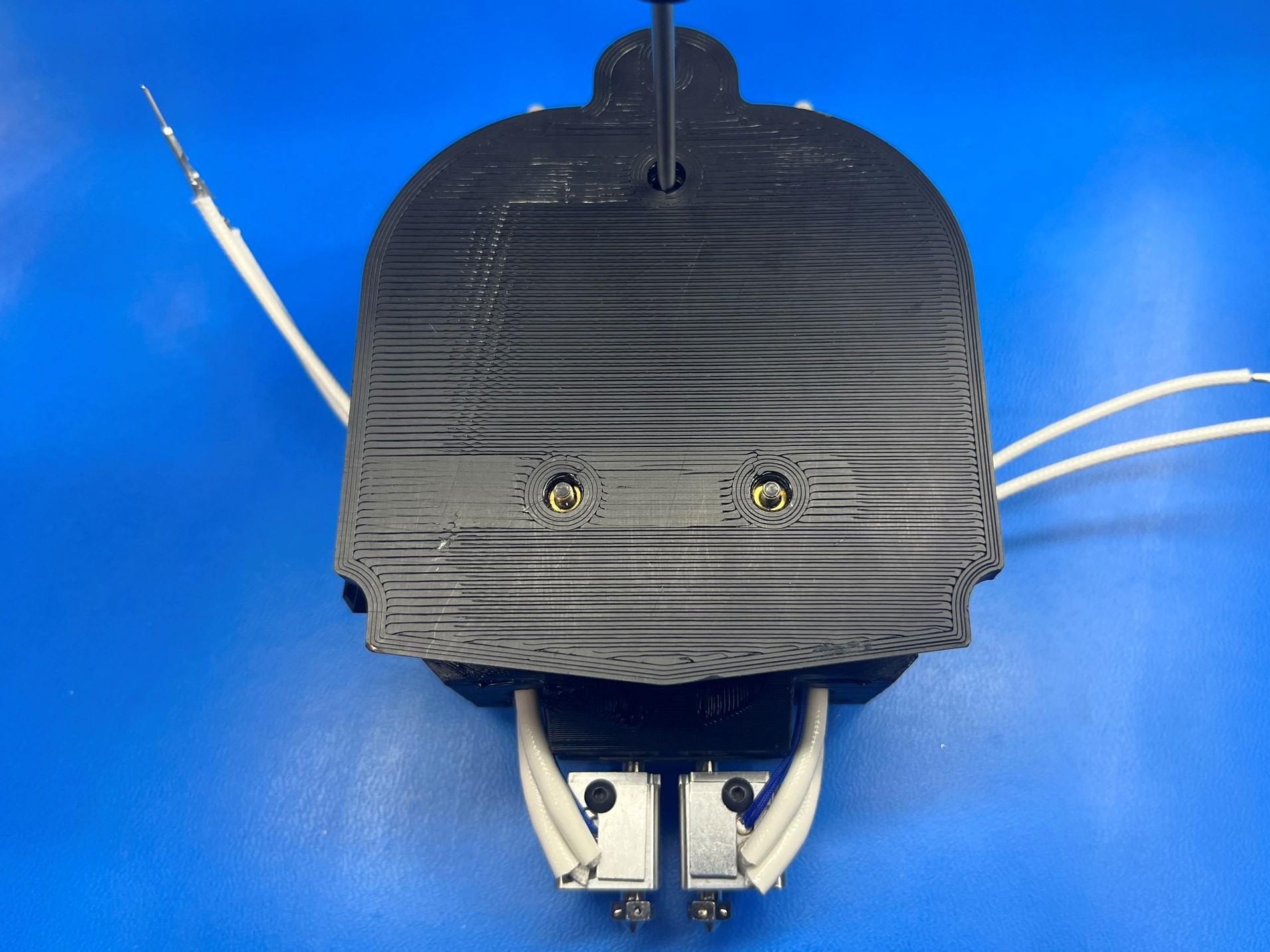
Once the wire are tucked away flip the assembly over so that the backside of the dual mount is facing up. Use 1x M3x30 SHCS [HD-BT0042] with a M3 washer and secure the back side of the dual mount.
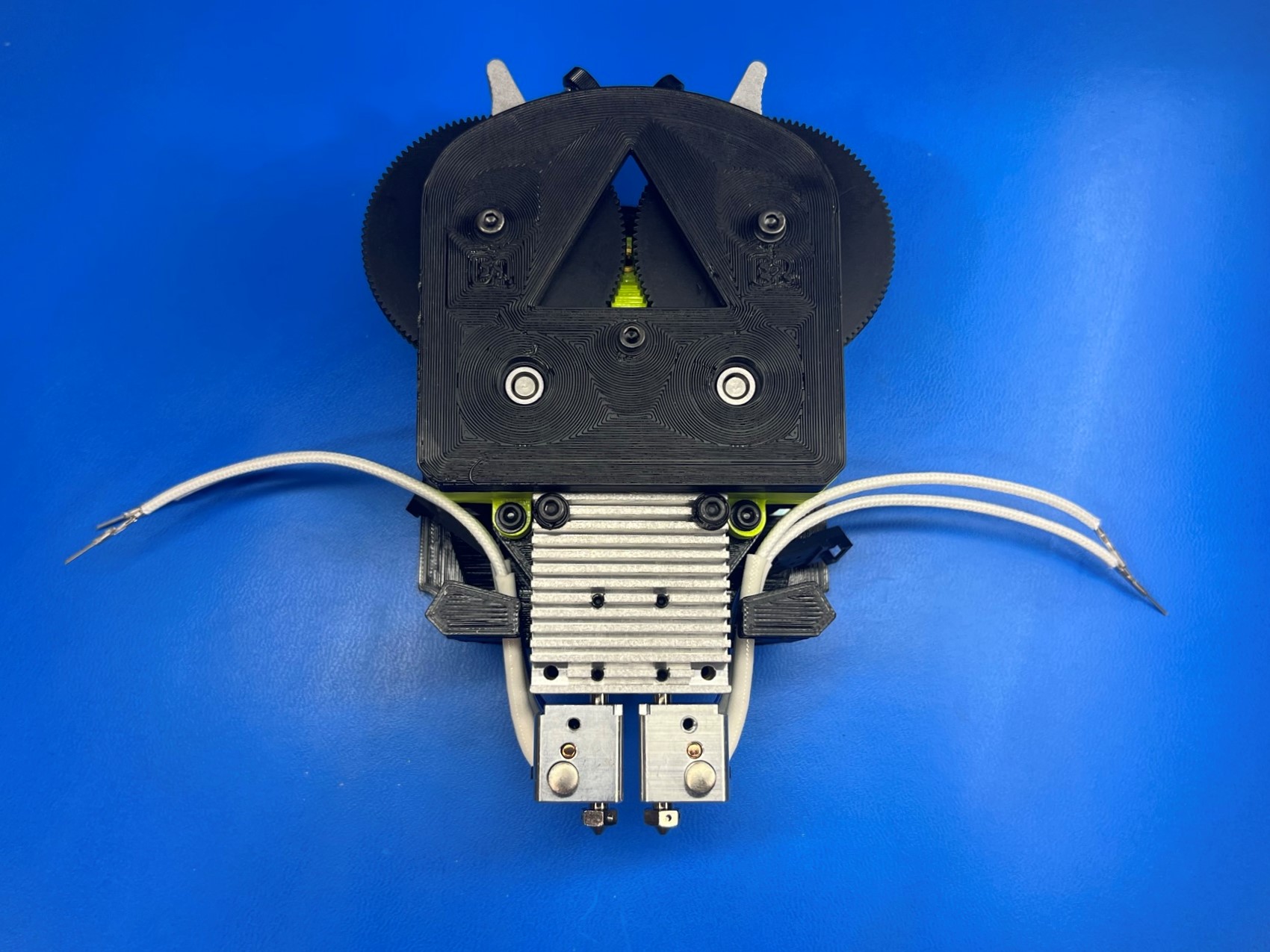
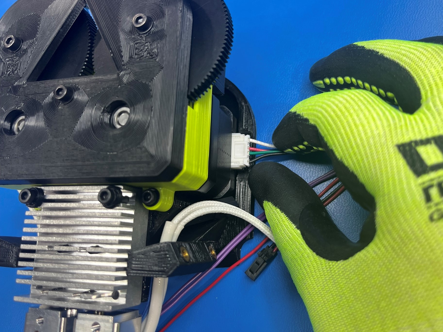
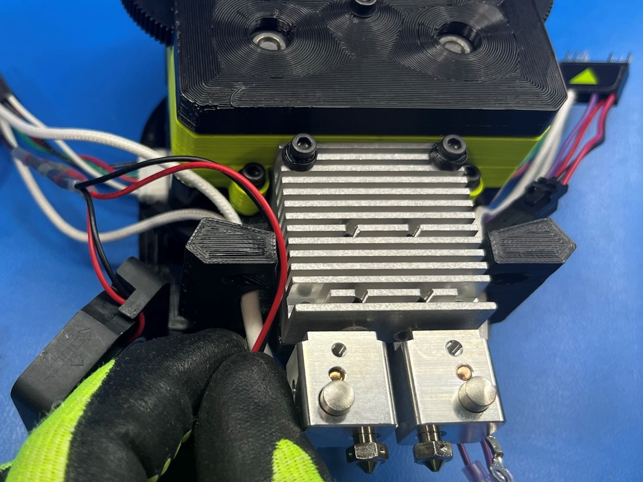
Connect the motor harness on the dual extruder harness 0 [AS-CB0042] to the right motor on the assembly.
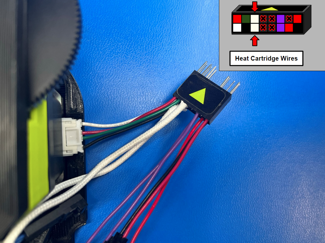
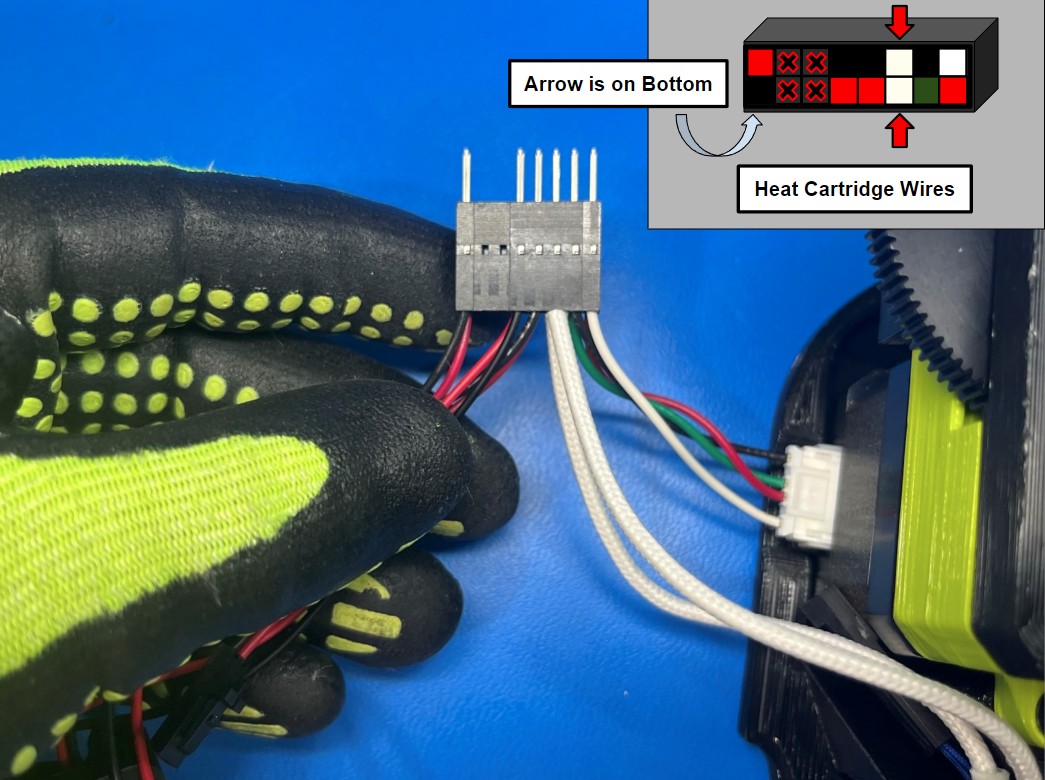
Then take the 2x white heat cartridge wires and connect them to the port next to the motor wires. Make sure the tab on the prong is facing the open square so that the wires lock in place.
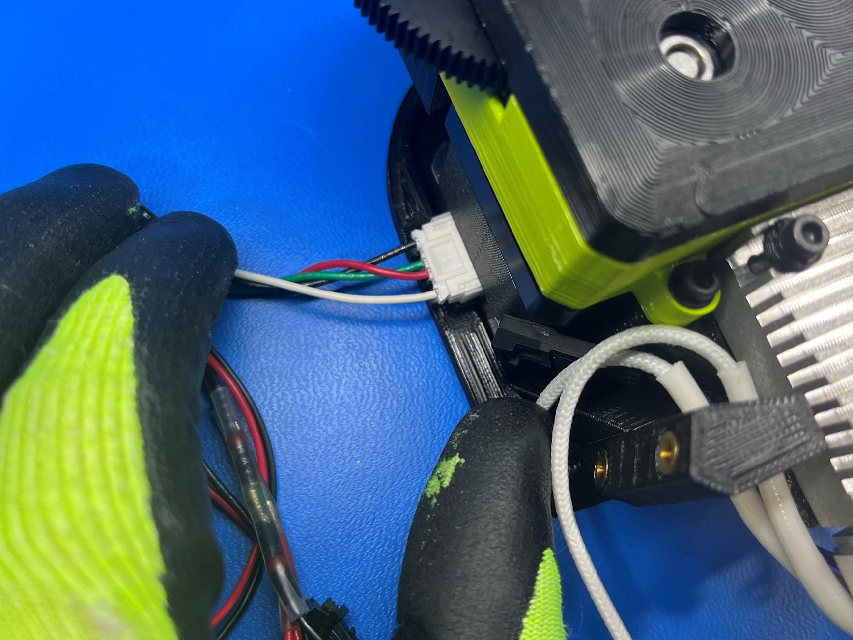
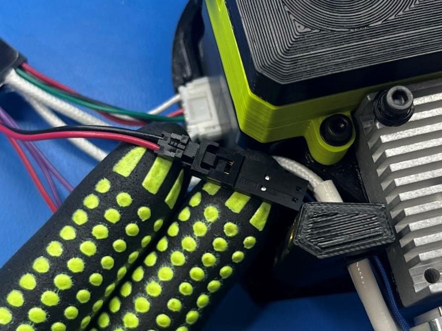
Now take the thermistor connector and connect it to the blue thermistor wire from the hot end.
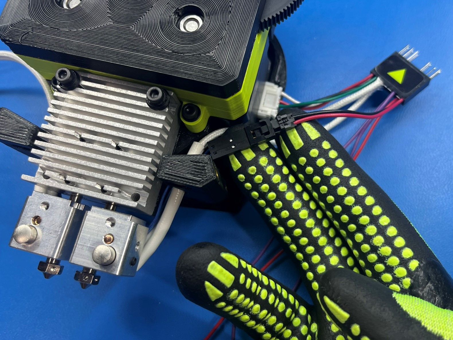
Once all the wires are connected make sure they are all routed through the gap between the heat sink and the dual mount.
Repeat the process for the dual extruder harness 1 [AS-CB0039], start with the motor harness and connect it to the left motor.
Then take the two white heat cartridge wire and connect them to the harness connector next to the motor wires.
Now take the thermistor connector and connect it to the blue thermistor harness on the hot end.
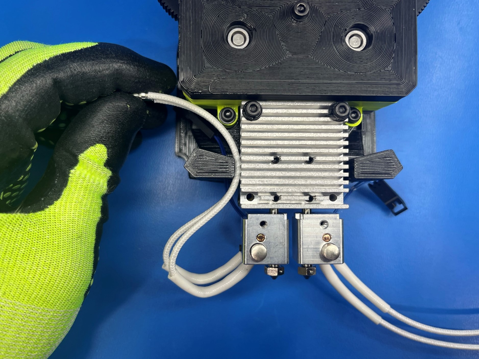
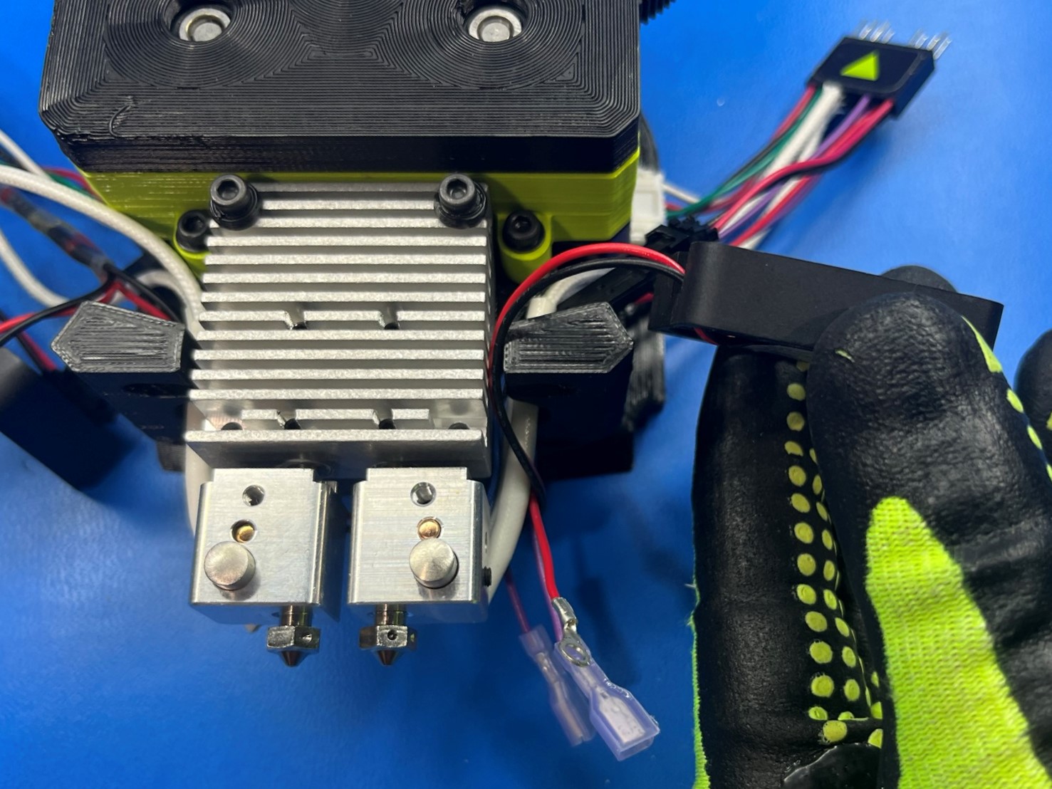
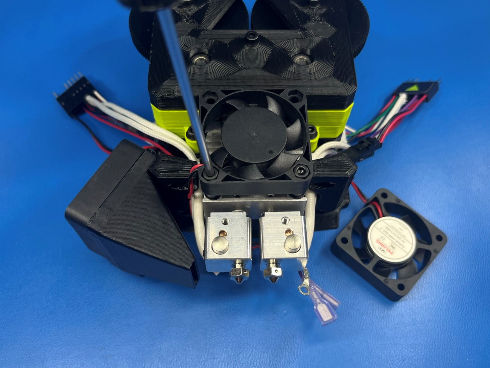
Find the long fan harness that has two fans connected to it and take the end fan and route it through the left gap. Then under and around the backside of the hot ends and back up through the right gap.
Then find the short fan harness and route that through the left gap.

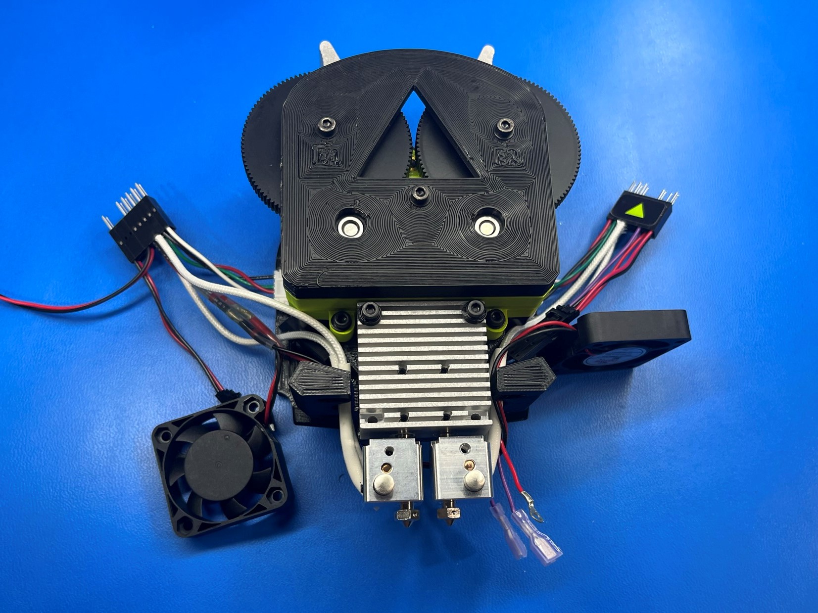
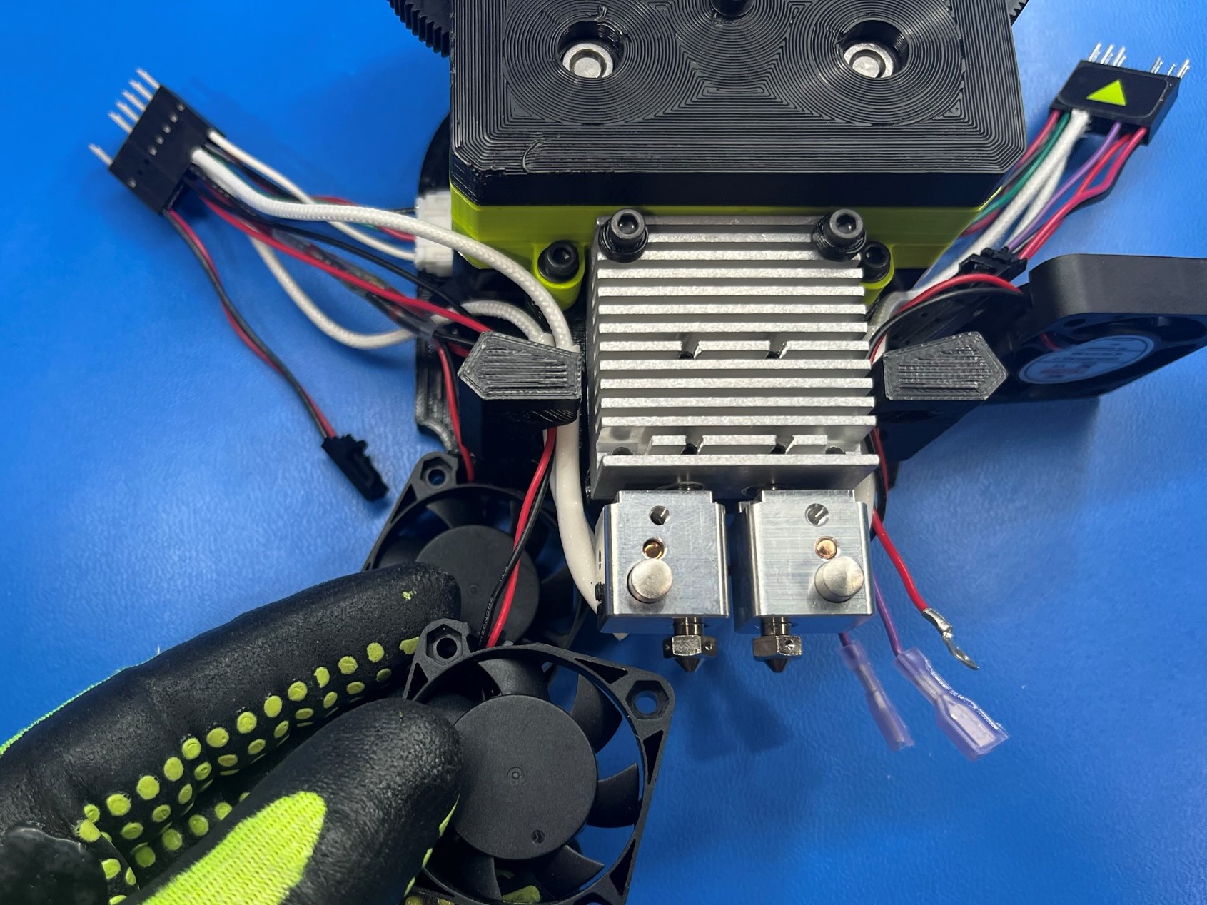
Take the dual duct left [PP-GP0288] and slide 2x M3x10 FHCS [HD-BT0116] through the two countersunk holes, then attach it to the left fan mount on the dual mount.
Now place the fan over the dual fan duct left and secure it using 2x M3x12 SHCS [HD-BT0039] make sure the wire are toward the center of the assembly and that the fan sticker is facing down.
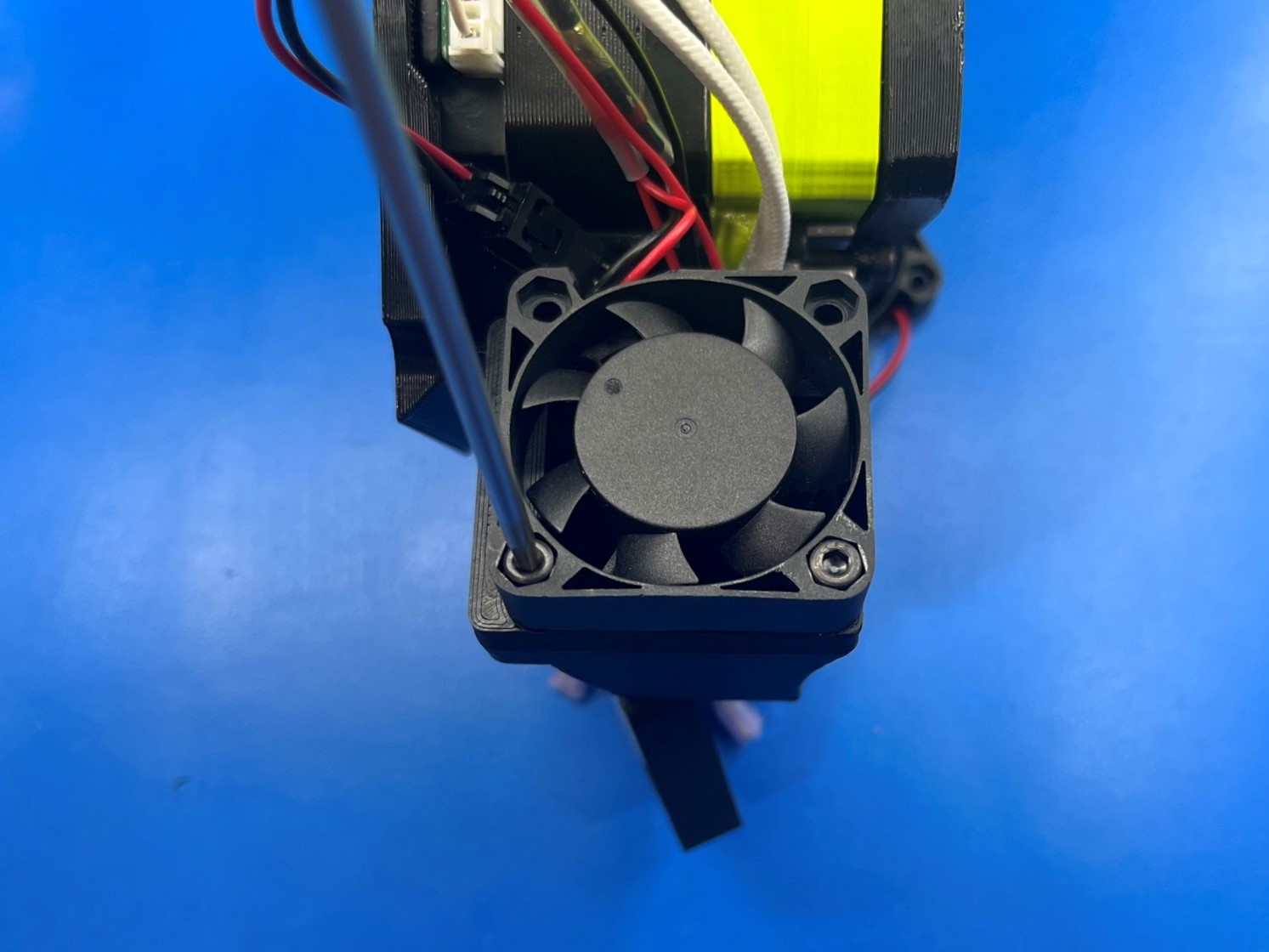
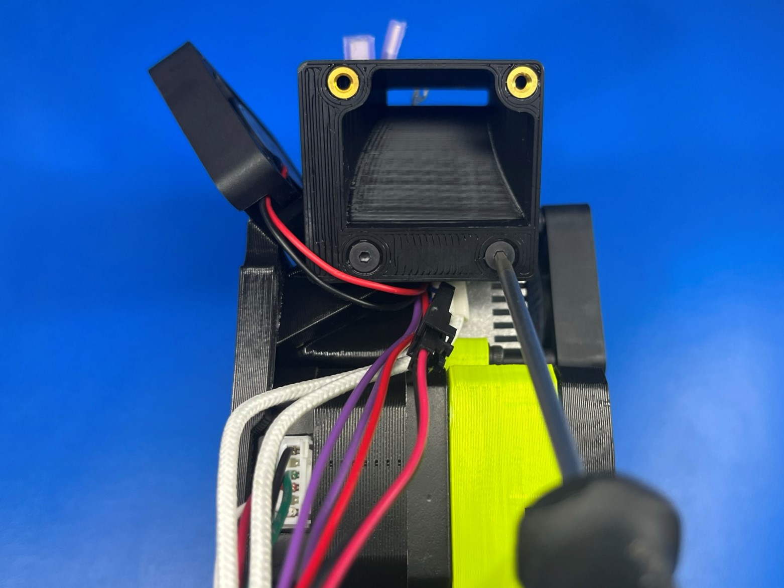
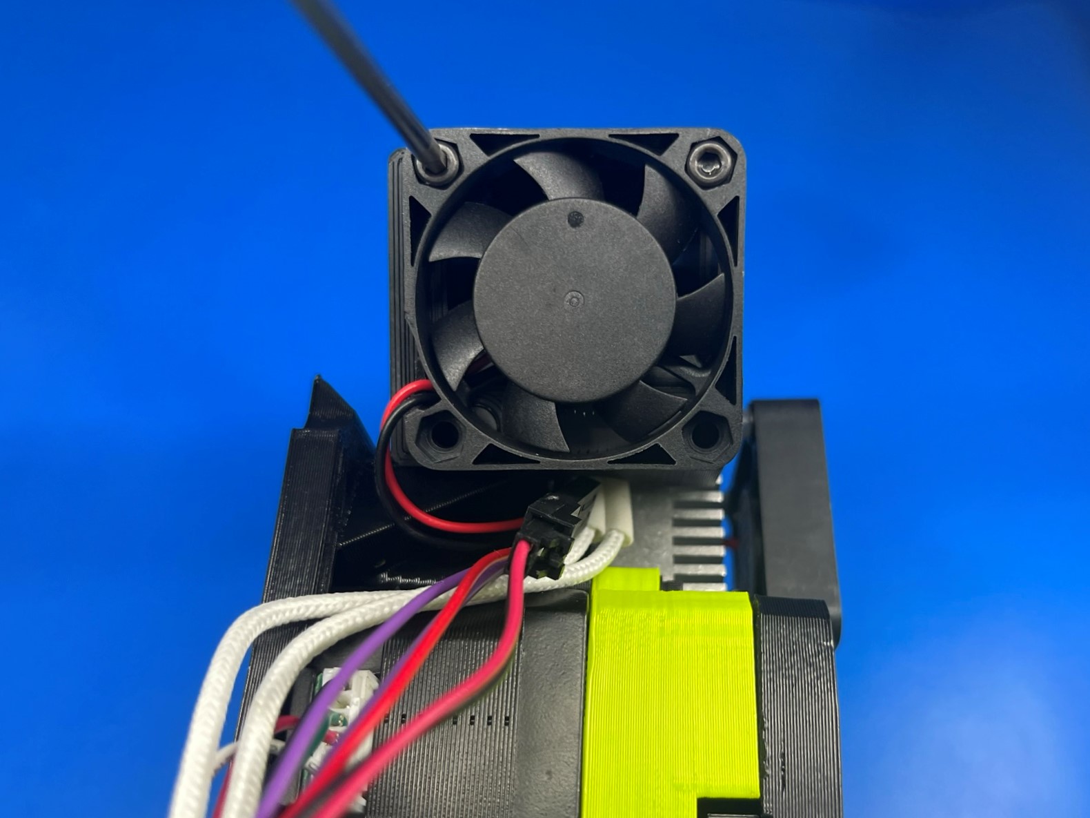
Before attaching the center fan to the heat sink you need to prepare the spacers. Take 1x M3x35 SHCS [HD-BT0043] And slide it through the bottom right hole on the fan. Then slide 1x M3 washer [HD-WA0038], 1x LCD spacer [HD-MS0555], followed by one more M3 washer.
Then repeat for the bottom left hole and attach to the heat sink,
Repeat the dual duct left process for the dual duct right [PP-GP0289]. Make sure the fan has it wires pointed back with the sticker facing down.
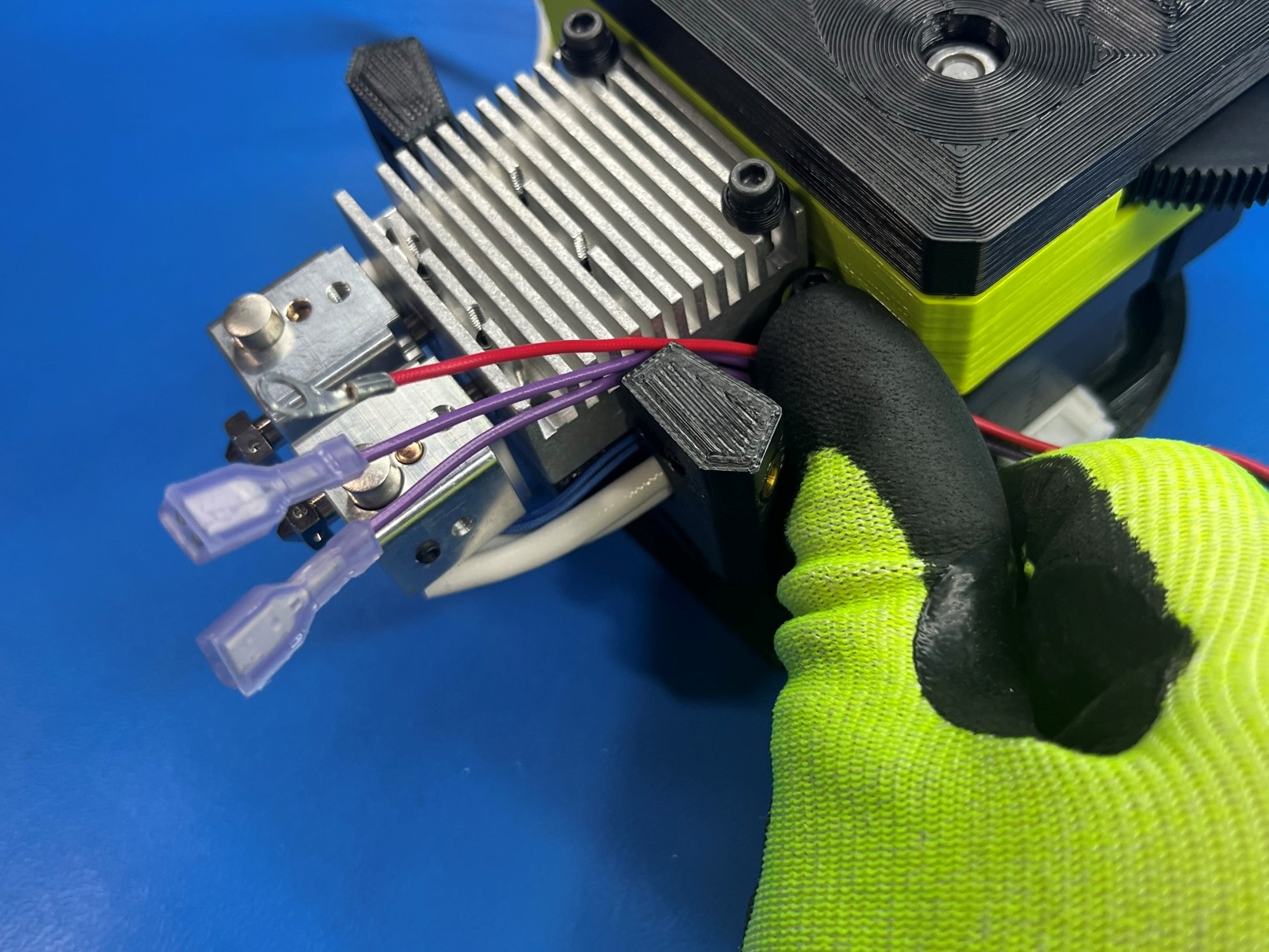
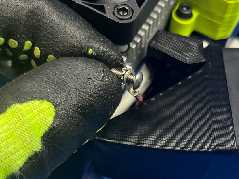
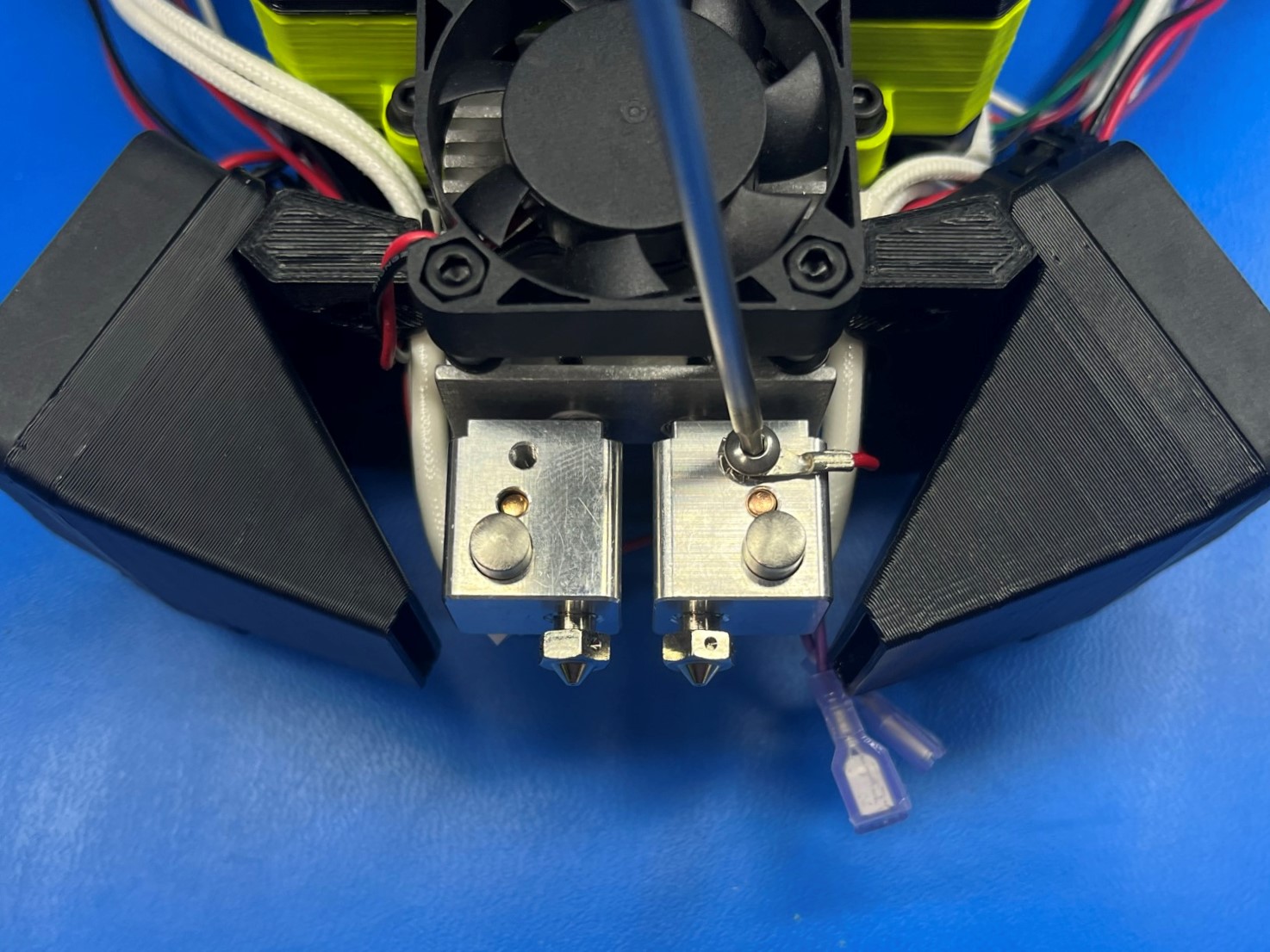
Take 1x M3x8 SST BHCS [HD-BT0104] and slide the red zero sense wire over the bolt with an M3 lock washer [HD-WA0035].
Then fasten the bolt to the right hot end in the top hole.
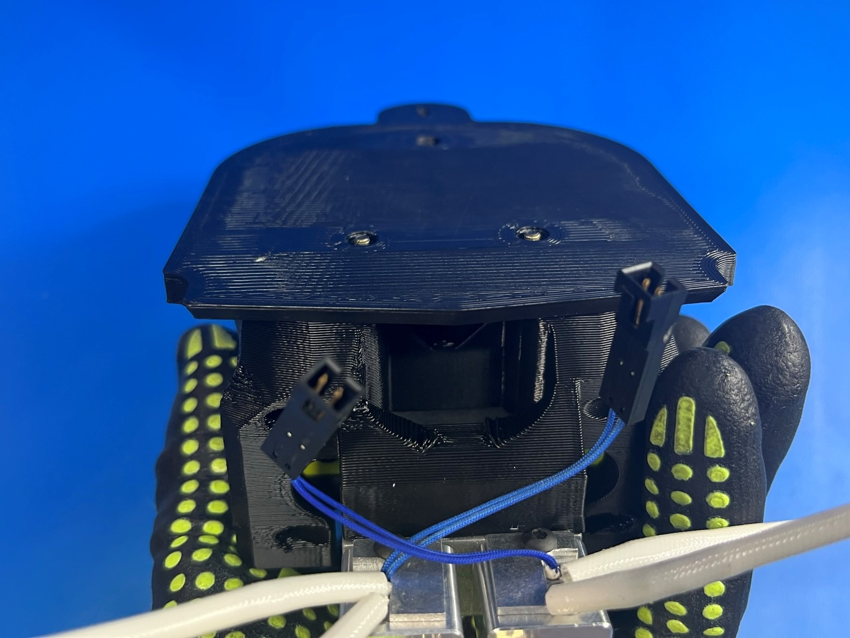
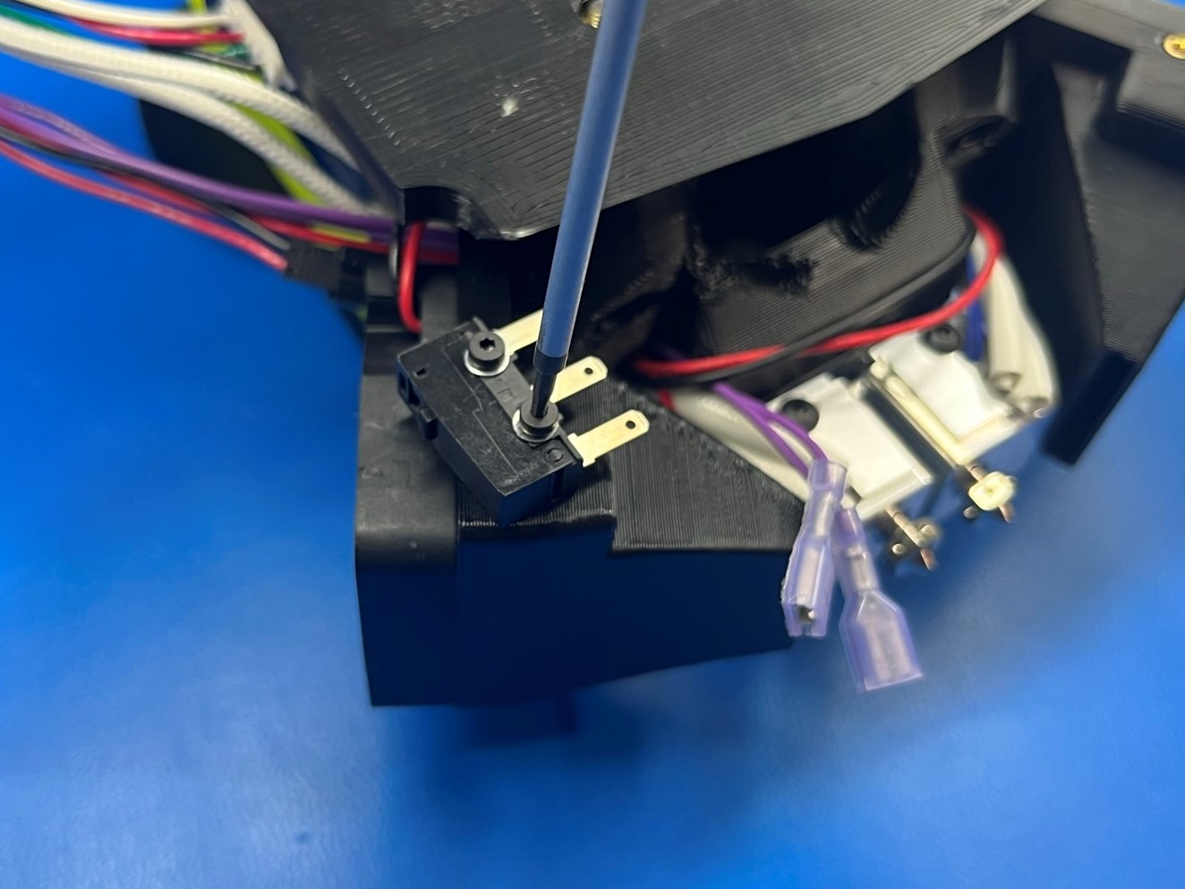
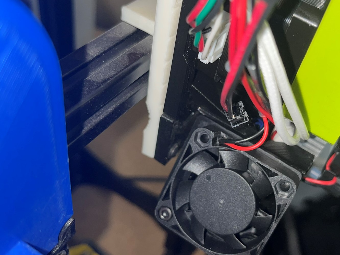
Turn the tool head over so that the back of the assembly is facing up then find the two purple wires. This will be the side that we install the limit switch [EL-SW00022] on.
Use 2x M2x10 SHCS [HD-BT0107] with M2 washers [HD-WA0012] to mount the limit switch to the dual duct right making sure the tabs are facing the center of the assembly.
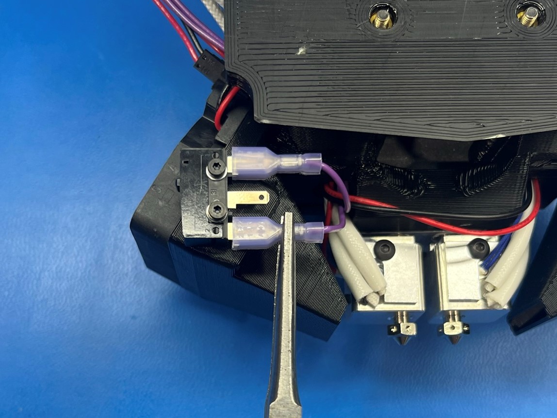
Then connect the two purple wire to the two outside tabs on the limit switch.
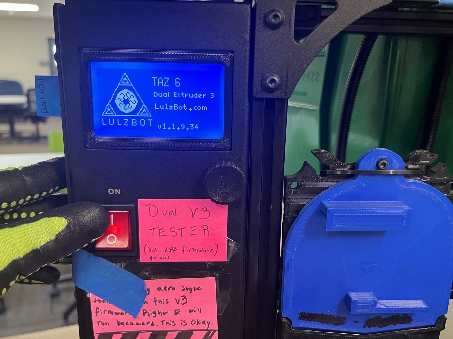
Slide the top of the dual mount through the cable tie on the test stand, then align the bottom of the dual mount with the shelf on the test stand.
Then connect both extruder harnesses to the test stand, make sure the alignment arrows are aligned.
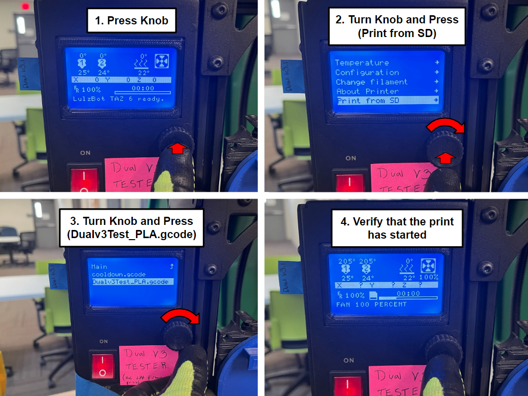
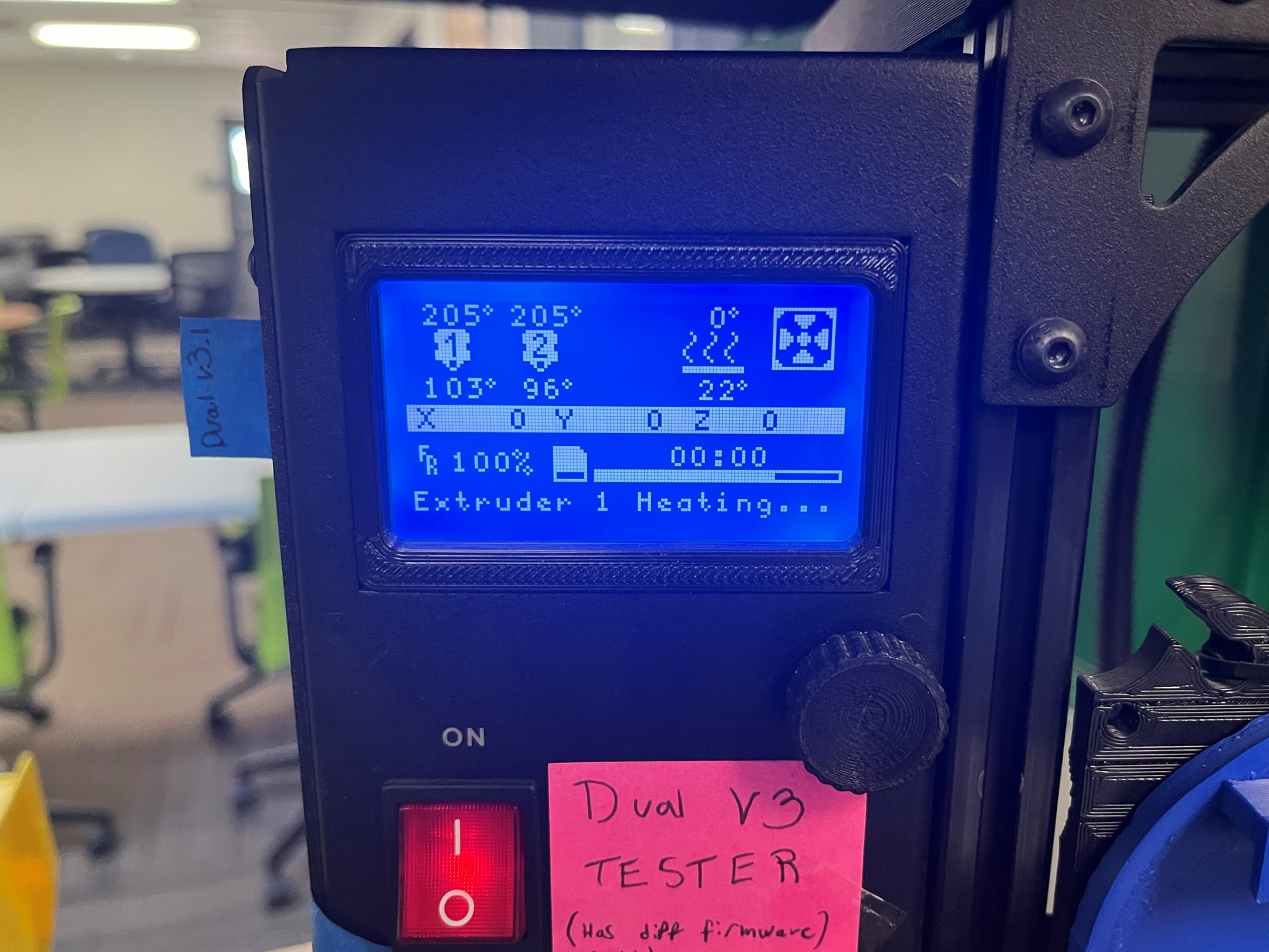
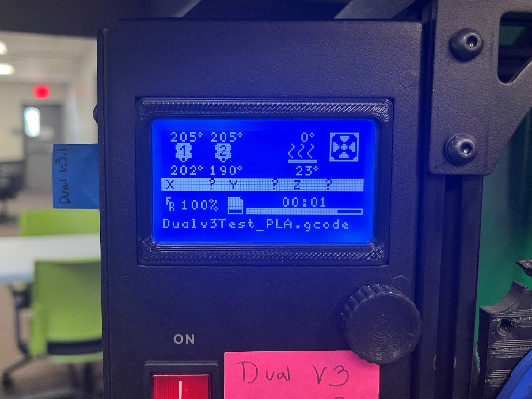
Once the tool head is connected turn the test stand on and go to the printer menu by pressing the LCD knob. Then scroll down to Print from SD and select it, then select the Dualv3Test_PLA.gcode and make sure to start the print.
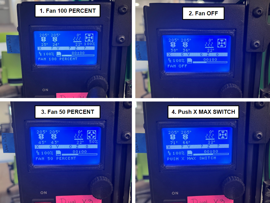
When the test starts it will show the fan running at 100 percent then it will shut off and finally at 50 percent.
Then it will ask for you to PUSH X MAX SWITCH find the switch on the right side of the tool head and press the button.
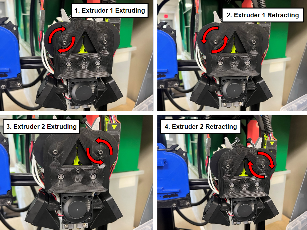
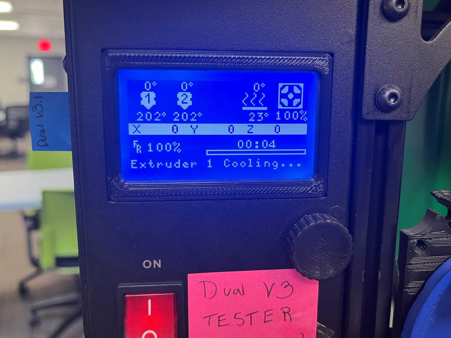
Then both hot ends will continue to heat up until they reach 205 or come close to it. The left hobb gear will begin to extrude then retract making sure the motor is working correctly. Once the left hobb gear finishes the right will begin.
Once both side of the tool head checked the motor the hot ends will begin cooling, at this point if the tool head didn't have any problems it passes the test and you may remove it once it temperature is lower then 45 degrees C.


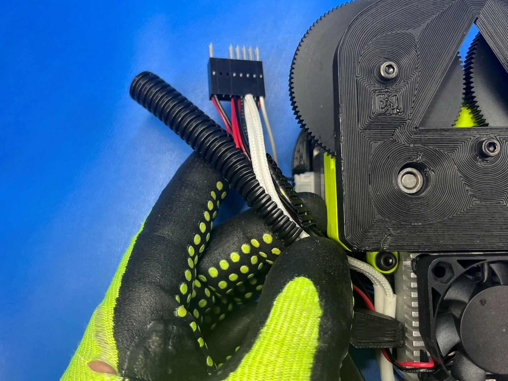
Take a section of the tubing corrugated loom 3/8" [EL-MS0139] and wrap it around the left extruder harnesses making sure to get all the wires inside the loom except the motor wires. Its easiest to open one end and wrap it around the wires then slide it down continuing to push the wires inside the loom.
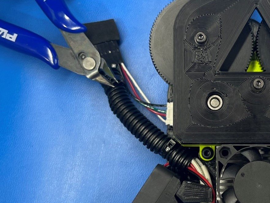
Once the loom is containing the wires add a cable tie [HD-MS0058] to both ends to secure the loom. Once the cable ties are tight, trim the ends.
Repeat process for the right side.
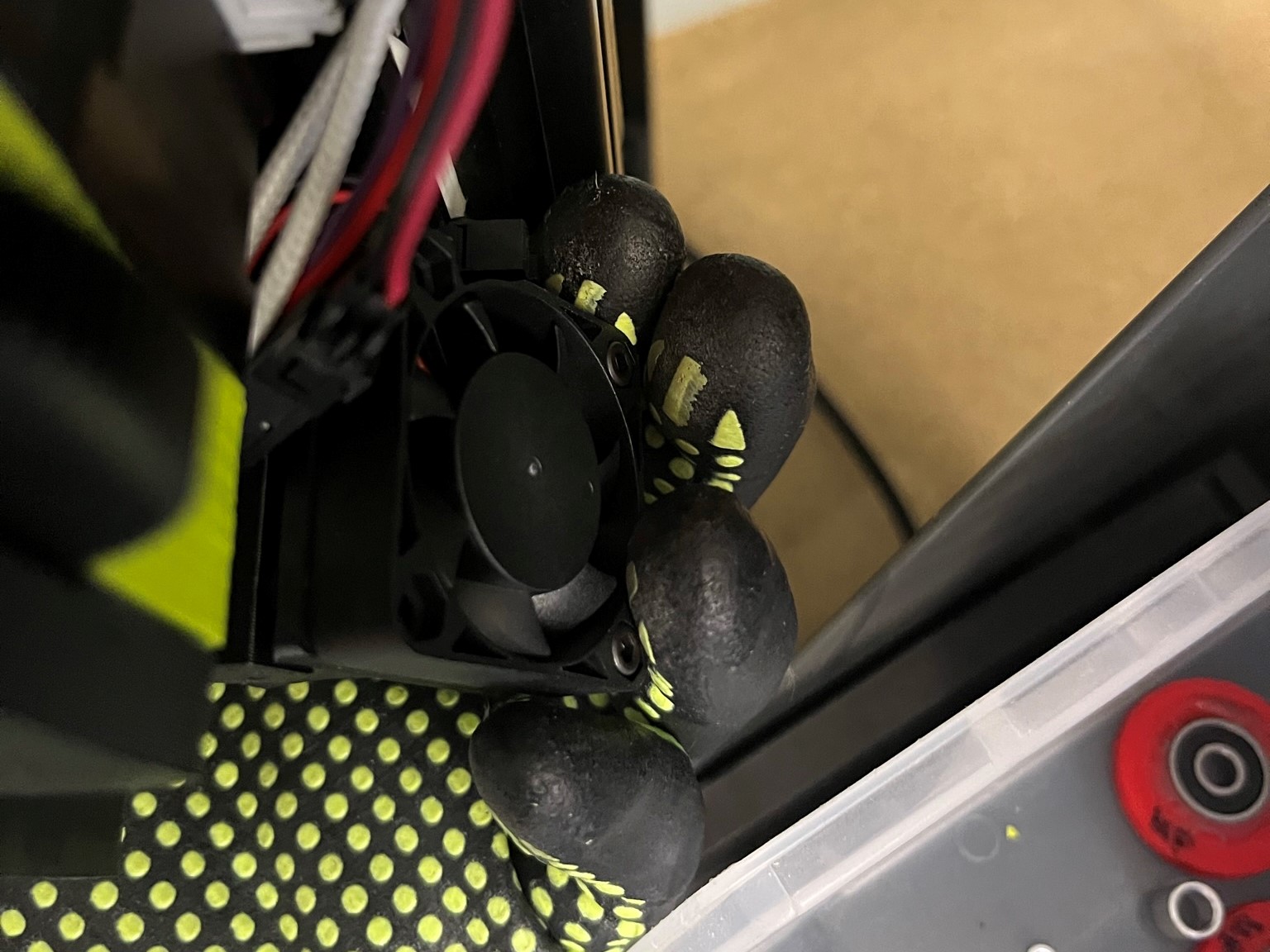
Once the loom is on both sides stick foam 1.06"x.6"x.3" extruder pin insertion [HD-MS0375] on both pin connectors. This protects the pins from getting damaged.