Open HardwareAssembly Instructions
Guides for installation and assembly of the LulzBot line of products made by FAME 3D LLC.
Guides for installation and assembly of the LulzBot line of products made by FAME 3D LLC.
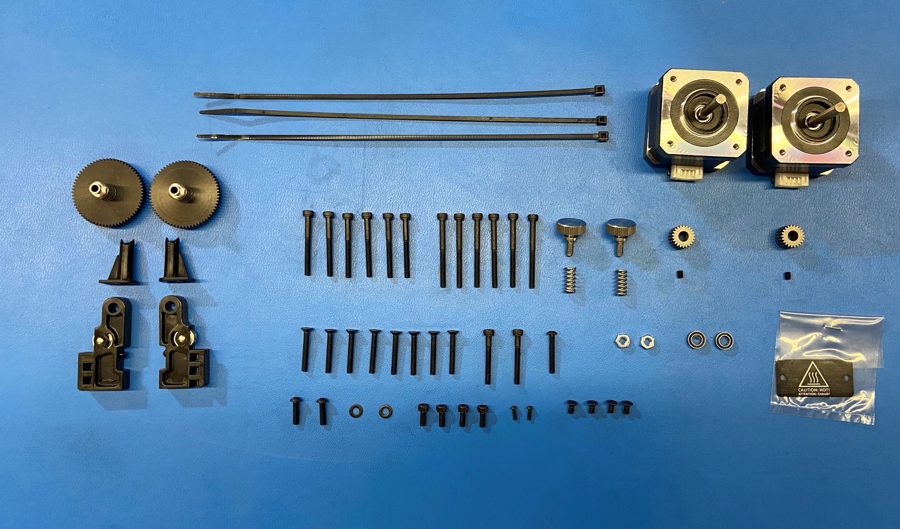
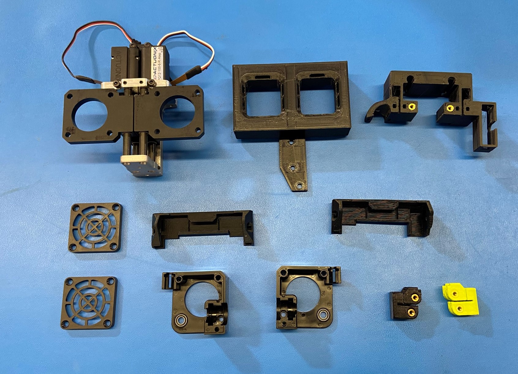
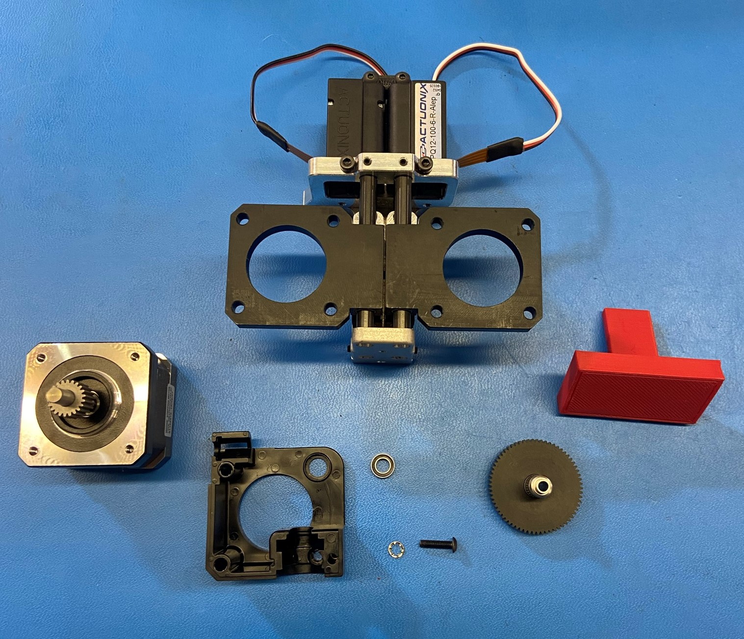
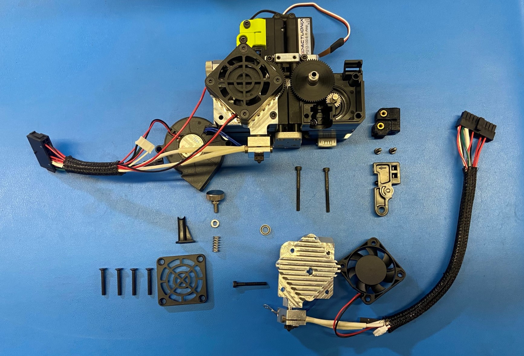
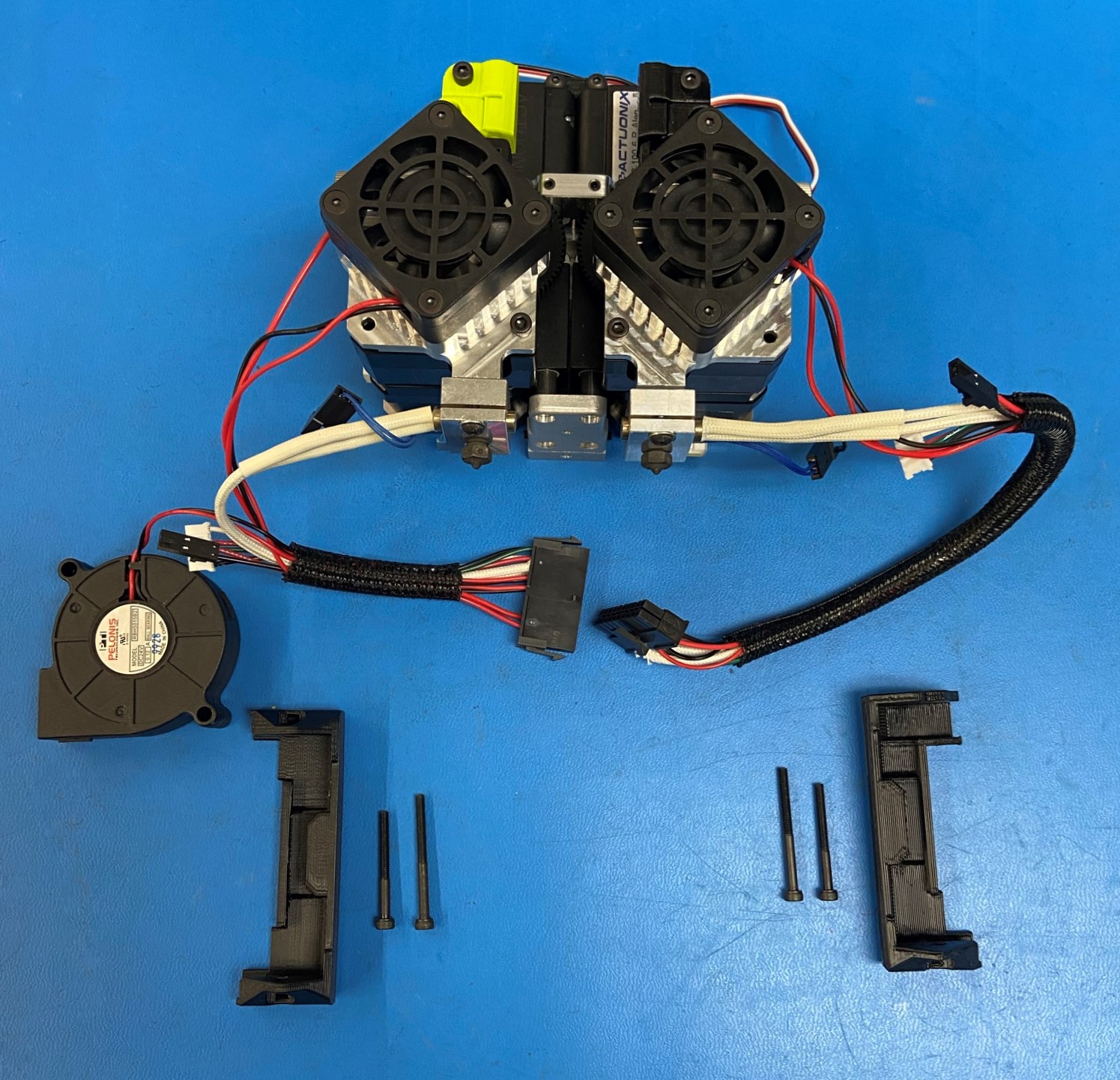
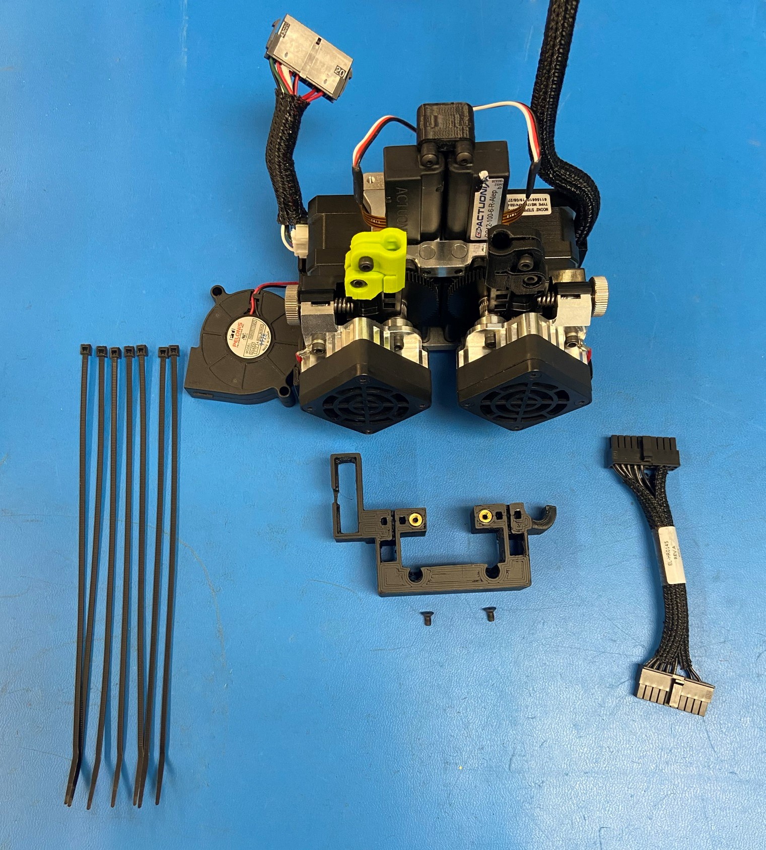
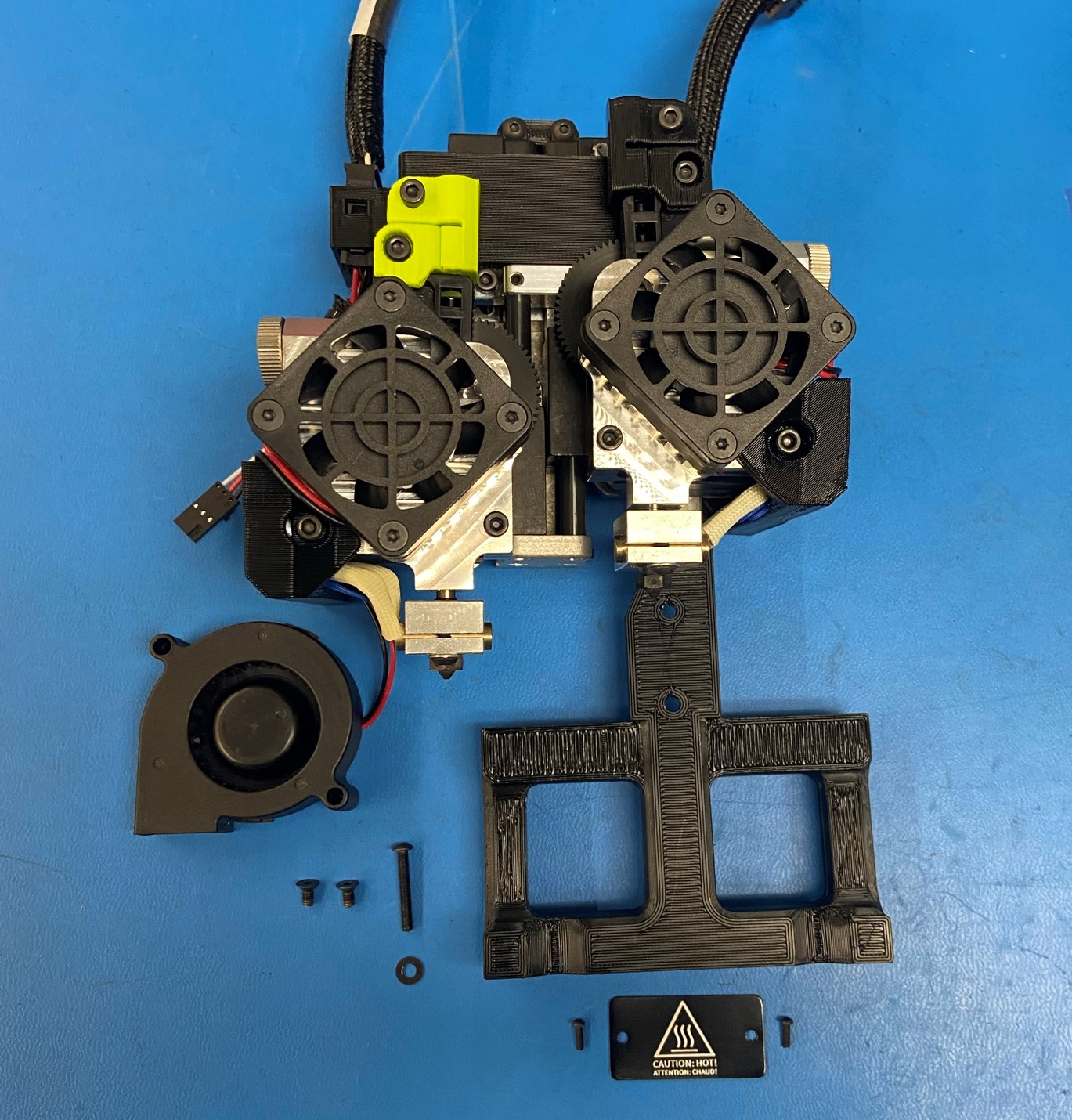
Gather all the required materials:
1x- Actuator Sub-Assembly
2x- [HD-BT0235] M2x0.4 BHCS
2x- [HD-BT0041] M3x25 SHCS
6x- [HD-BT0042] M3x30 SHCS
6x- [HD-BT0043] M3x35 SHCS
4x- [HD-BT0157] M3x8 SHCS
4x- [HD-BT0128] M3x6 FHCS
2x- [HD-BT0146] M3x12 BHCS
2x- [HD-BT0162] M3x4 Set screw
1x- [HD-BT0171] M3x20 BHCS
2x- [HD-BT0197] M4 Thumb screw
8x- [HD-BT0204] M3x22 FHCS
2x- [HD-MS0430] Idler spring
4x- [HD-MS0446] Bearing
2x- [HD-NT0011] M4 Nut
2x- [HD-WA0027] Lock washer
1x- [HD-WA0038] M3 washer
1x- [PP-GP0419] Blower shroud
1x- [PP-GP0428] Idler clamp right
1x- [PP-GP0427] Idler clamp left
1x- [PP-GP0470] Cable channel E1
1x- [PP-GP0471] Cable channel E2
1x- [PP-GP0420] Actuator cover
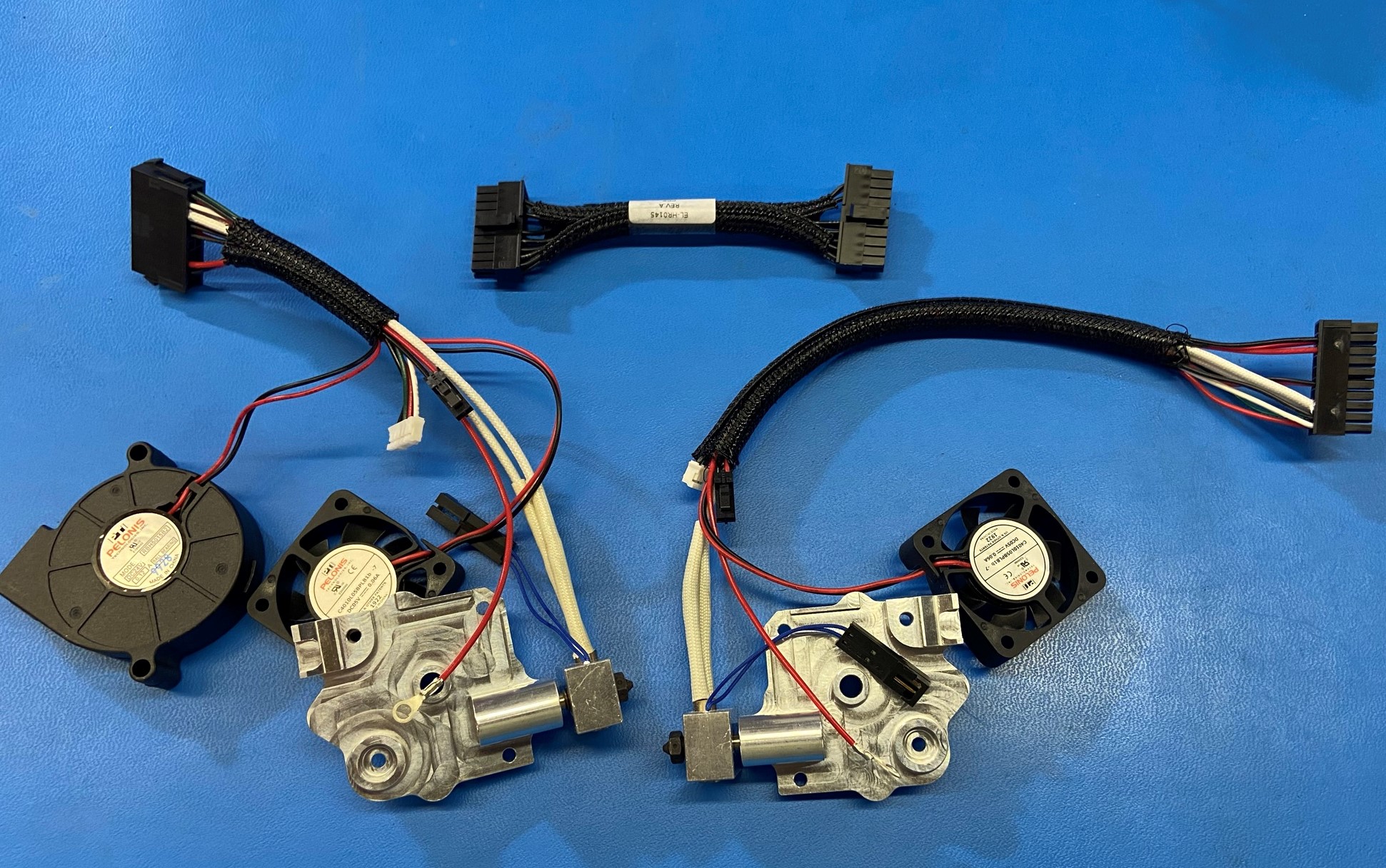
1x- [EL-HR0145] E1 Extension harness
1x- [EL-HR0165] Standard Aero Extruder Harness
1x- [EL-HR0166] Mirrored Aero Extruder Harness
2x- [EL-HR0170] Fan guard
2x- [EL-MT0069] Half height stepper motor
1x- [PP-FP0135] Mirrored Idler lever
1x- [PP-FP0136] Mirrored filament guide
2x- [PP-FP0154] Extruder hobb
1x- [PP-FP0158] Standard filament guide
1x- [PP-FP0162] Standard idler lever
1x- [PP-MP0204] Mirrored body
2x- [PP-MP0282] Steel pinion gear
1x- [PP-MP0233] Standard body
1x- [DC-LB0175] Caution Hot tag
5x- [HD-MS0058] Cable Tie
Materials:
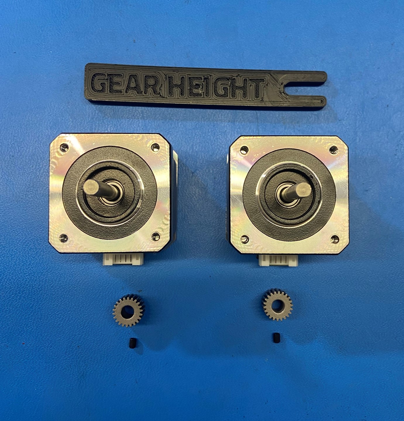
2x- [EL-MT0069] - NEMA 17 Half Height Stepper Motor
2x- [PP-MP0282] - E3D Aero Steel Pinion Gear
2x- [HD-BT0162] - Alloy Steel Cup Point Set Screw M3x4
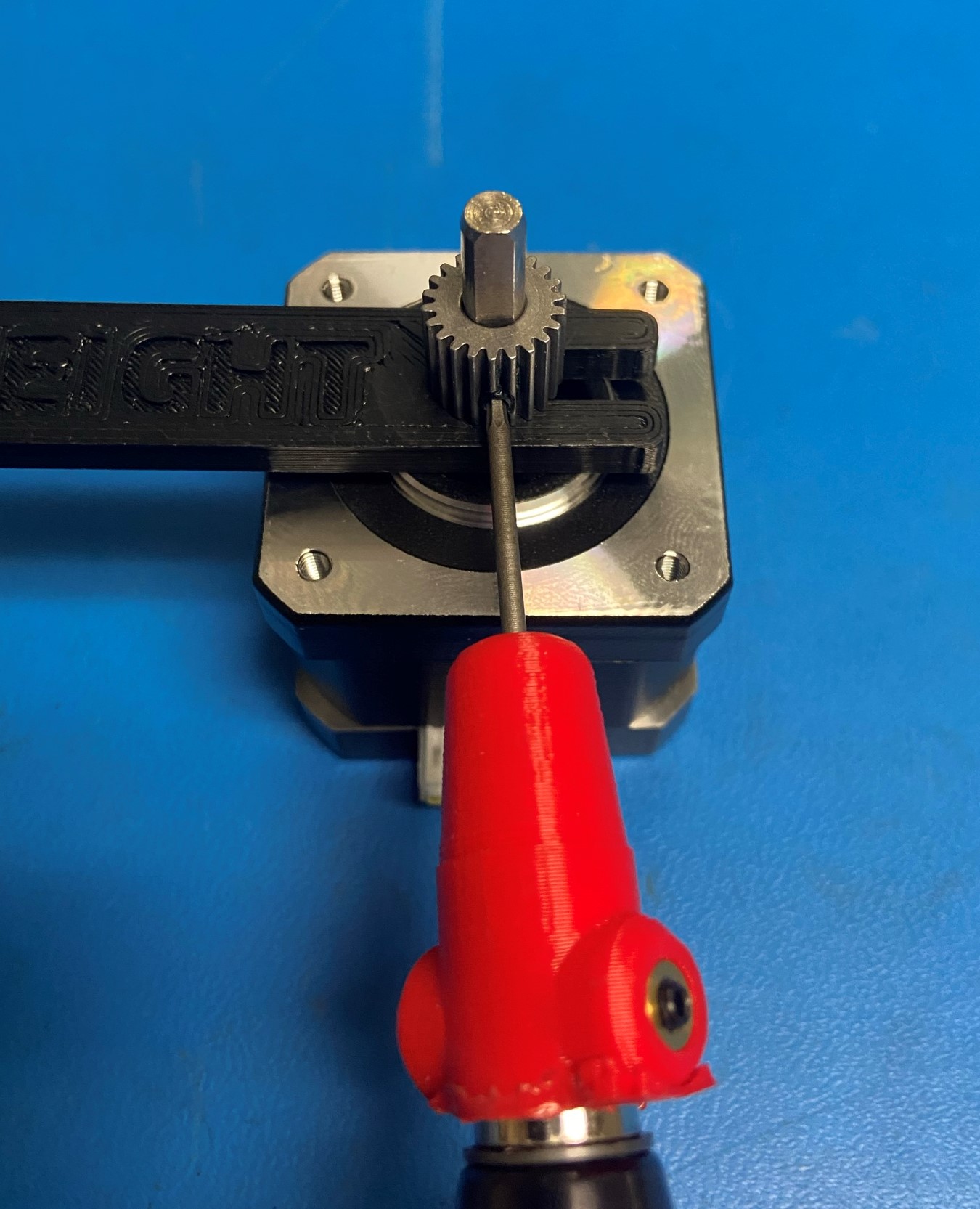
Using the GEAR HEIGHT spacing jig , line up the set screw with the flat side of the motor shaft.
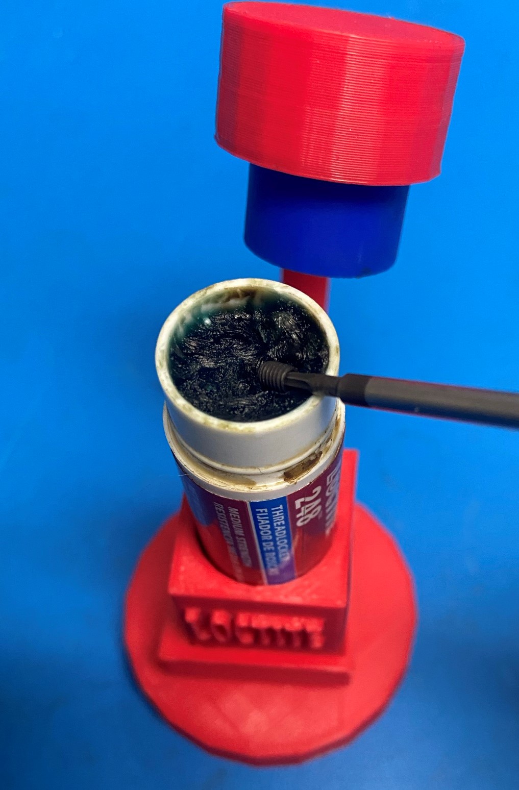
Apply Blue Loctite and torque the set screw to 3 in*lbs
Repeat for the second motor.
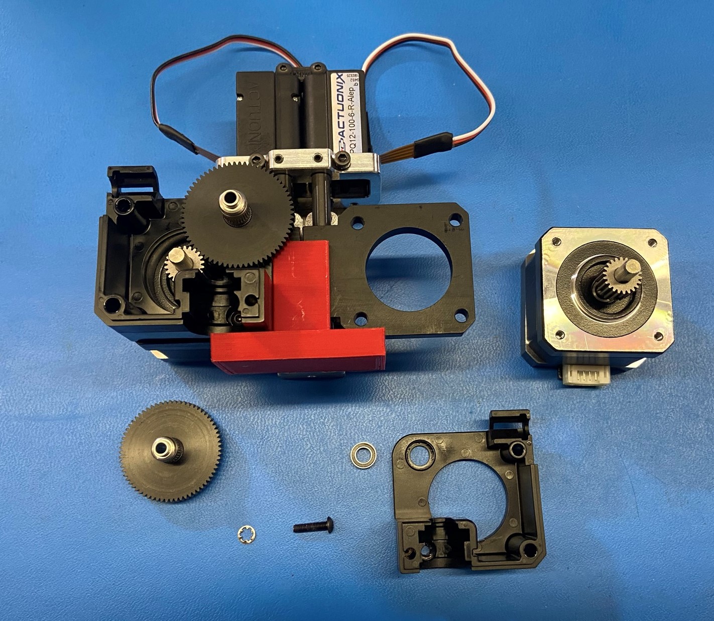
Materials:
Actuator Sub-Assembly
1x- Motor with pinion gear attached
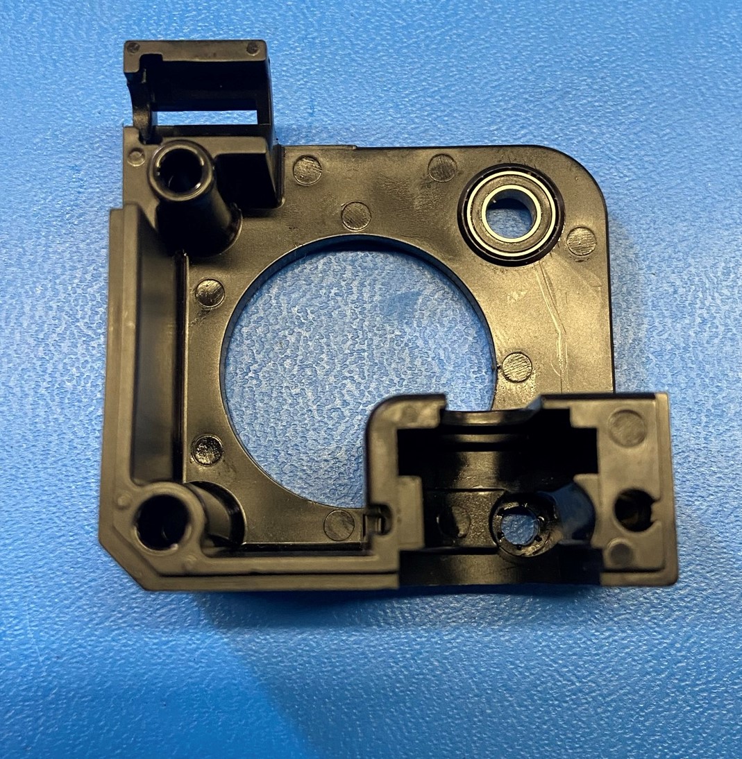
1x- [PP-MP0233] - Standard body
1x- [HD-WA0027] - Lock washer
1x- [HD-BT0146] - M3x12 BHCS
1x- [HD-MS0446] - Radial Ball Bearing
1x- [PP-FP0154] - Extruder hobb
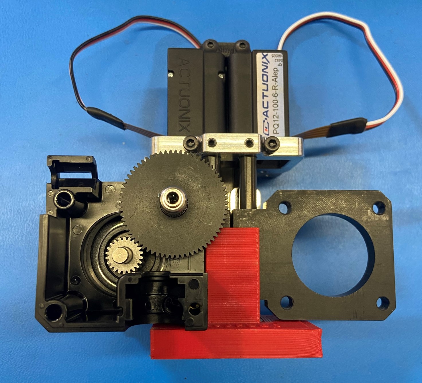
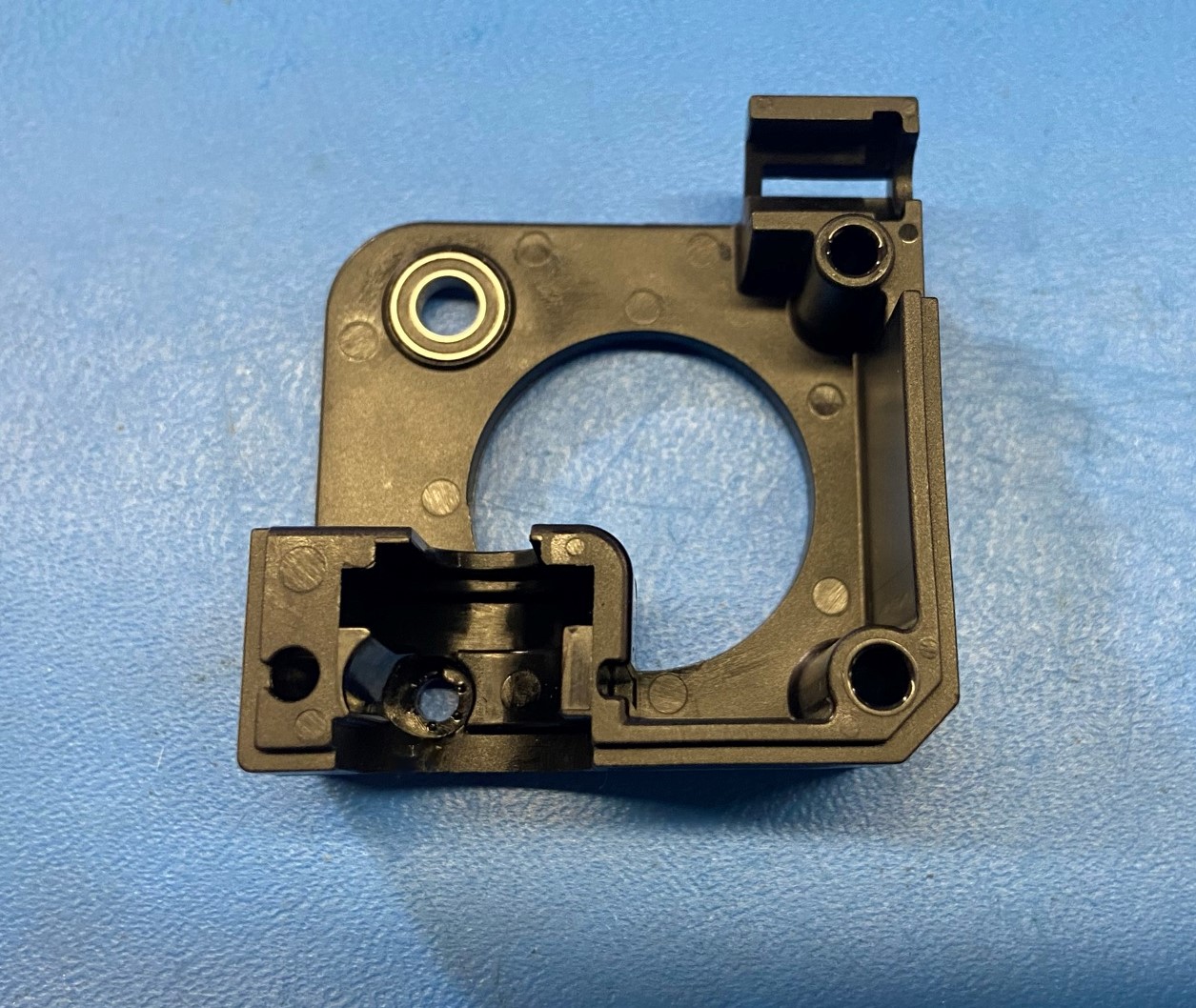
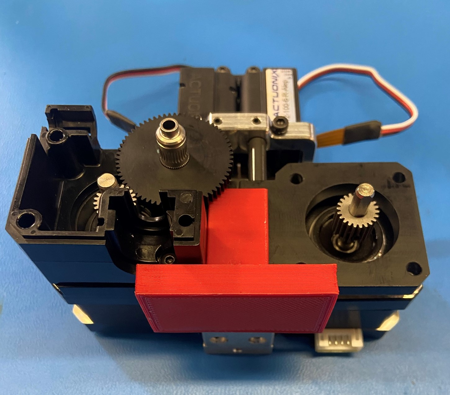
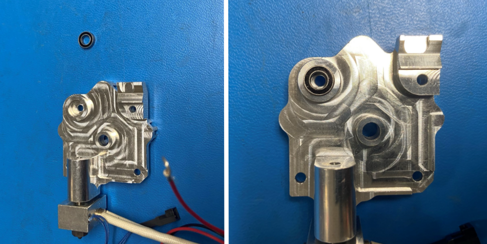
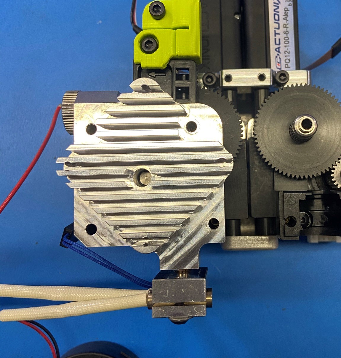
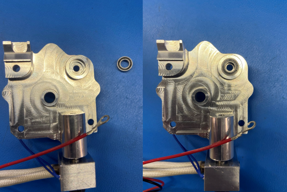
Start by installing the Radial Ball Bearing [HD-MS0446] into the Standard body [PP-MP0233]
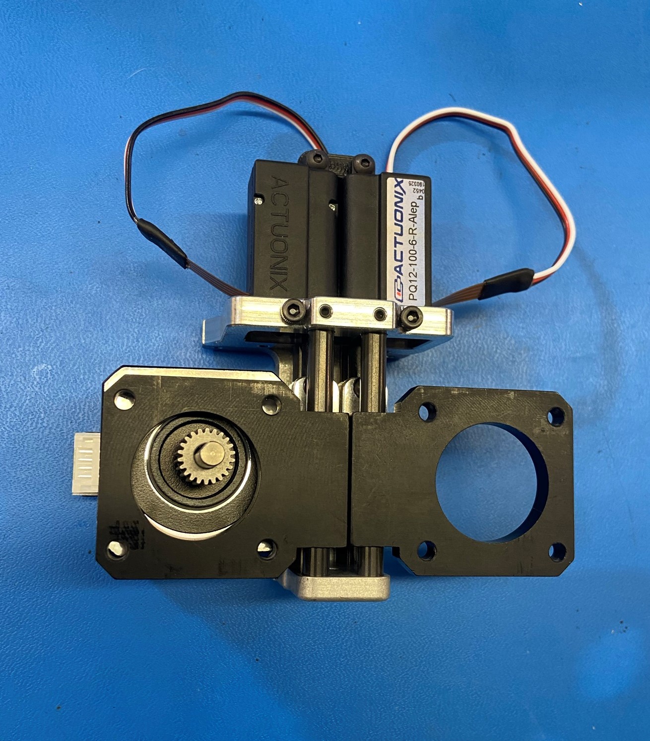
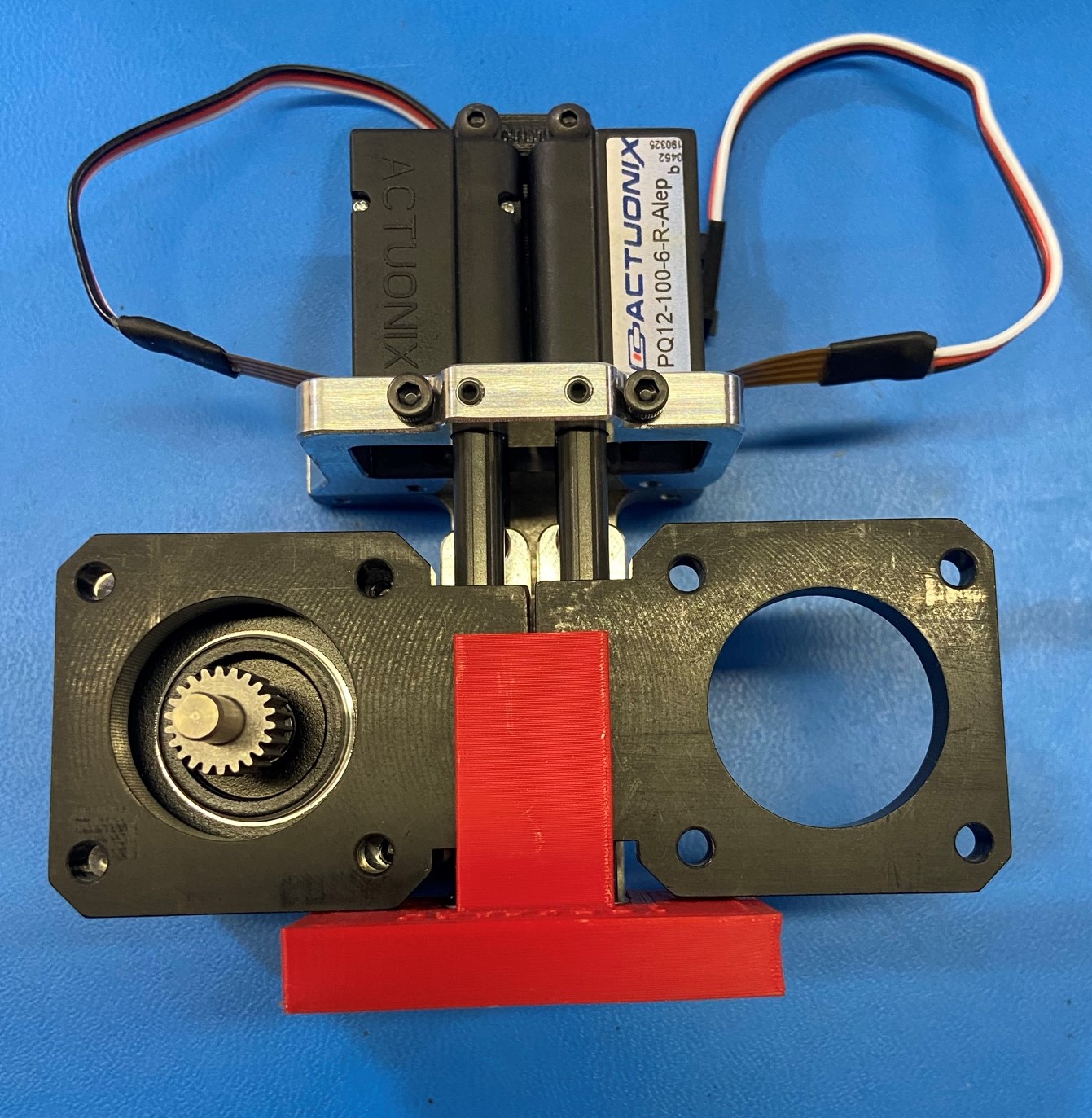
Next place motor with pinion gear under the motor plate on the actuator sub-assembly
Make sure the motor connector is facing the left as shown
Slide the jig over the bottom plate on the actuator sub-assembly and make sure the actuators are extended so the motor plates are tight against the jig.
Then place the standard body with bearing over the motor plate and insert the extruded hobb [PP-FP0154] through the bearing on the standard body.
Using 1x M3x12 BHCS [HD-BT0146] and 1x M3 Lock washer [HD-WA0027] while holding the motor up, so that the gears mesh together, secure the motor and standard body to the actuator sub-assembly.
Torque to 5in lbs
Materials:
Actuator Sub-Assembly (with jig still attached for step 3)
1x- Motor with pinion gear attached
1x- [PP-MP0204]- Mirrored body
1x- [HD-WA0027] - Lock washer
1x- [HD-BT0146] - M3x12 BHCS
1x- [HD-MS0446] - Radial Ball Bearing
1x- [PP-FP0154] - Extruder hobb
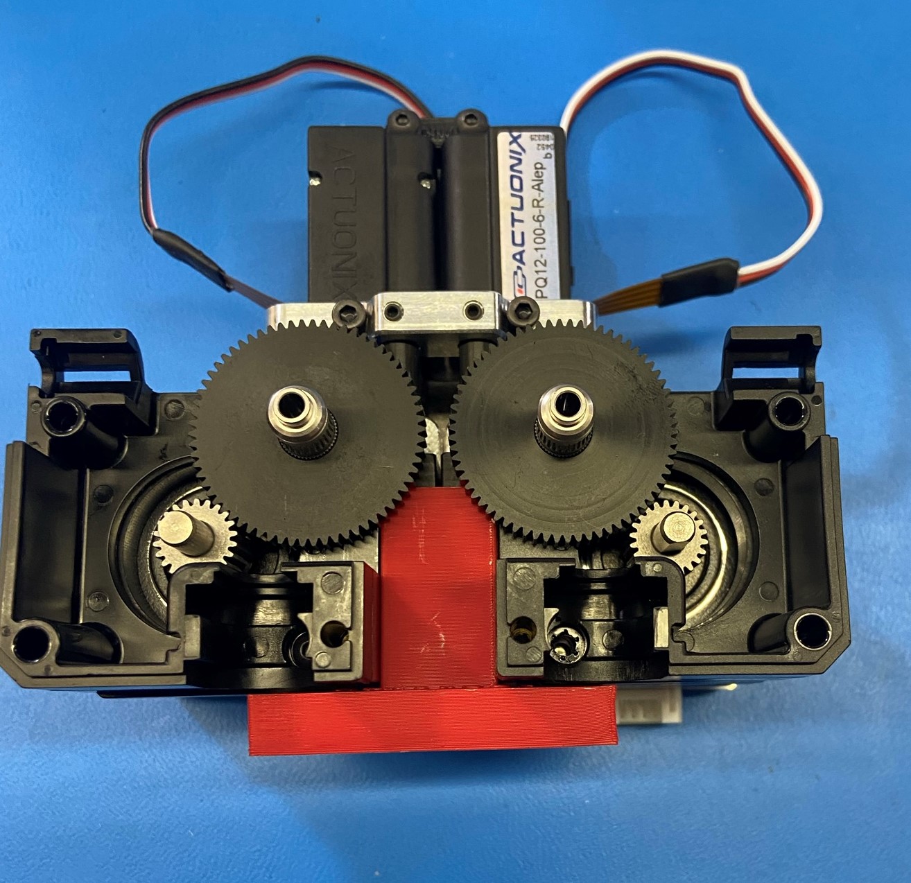
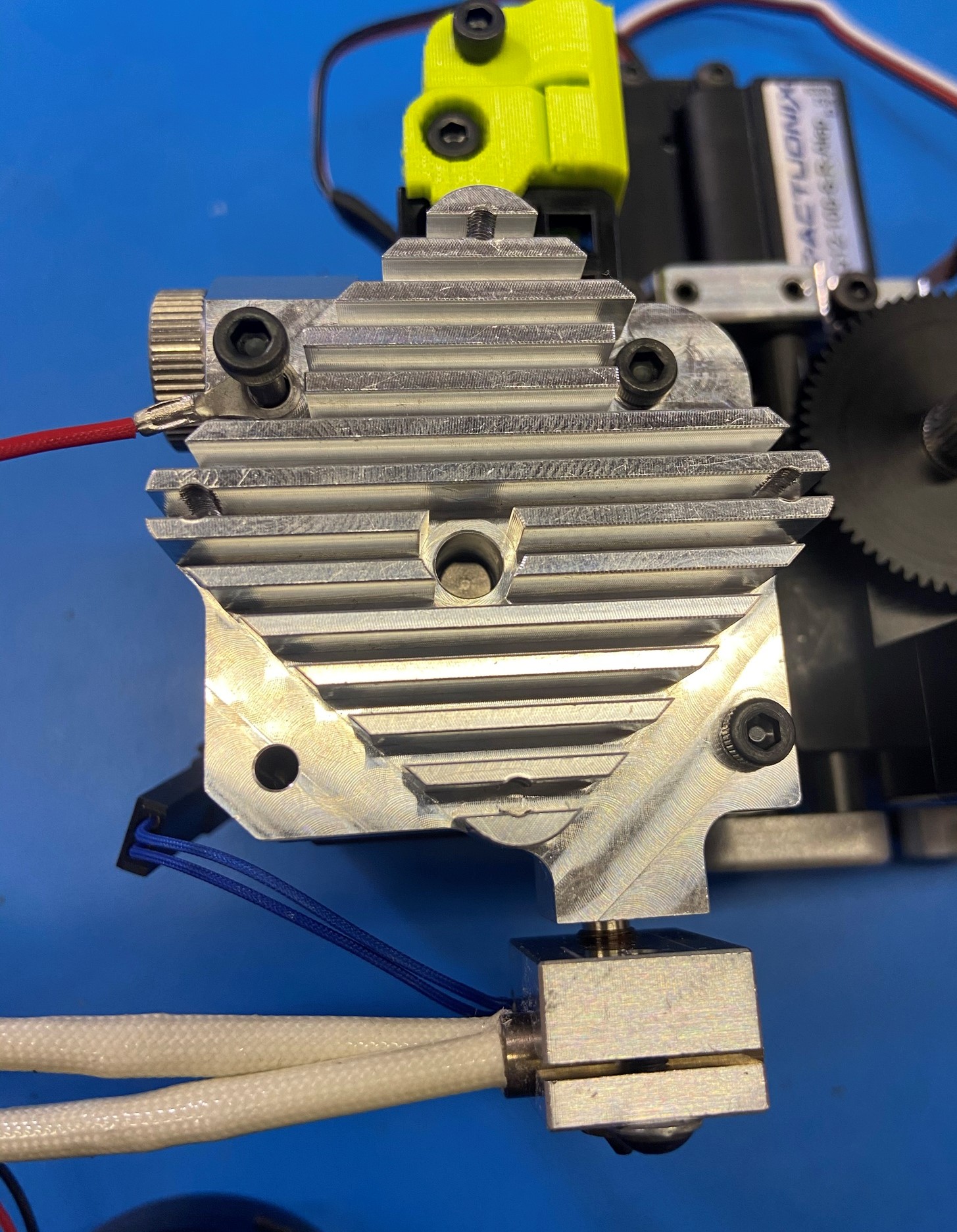
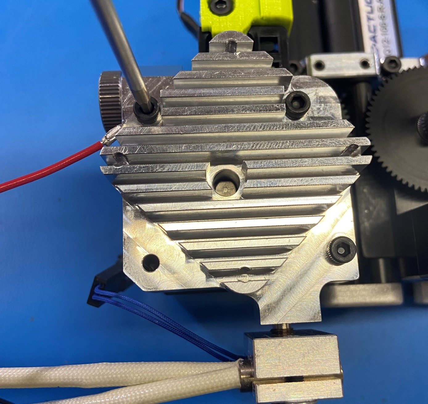
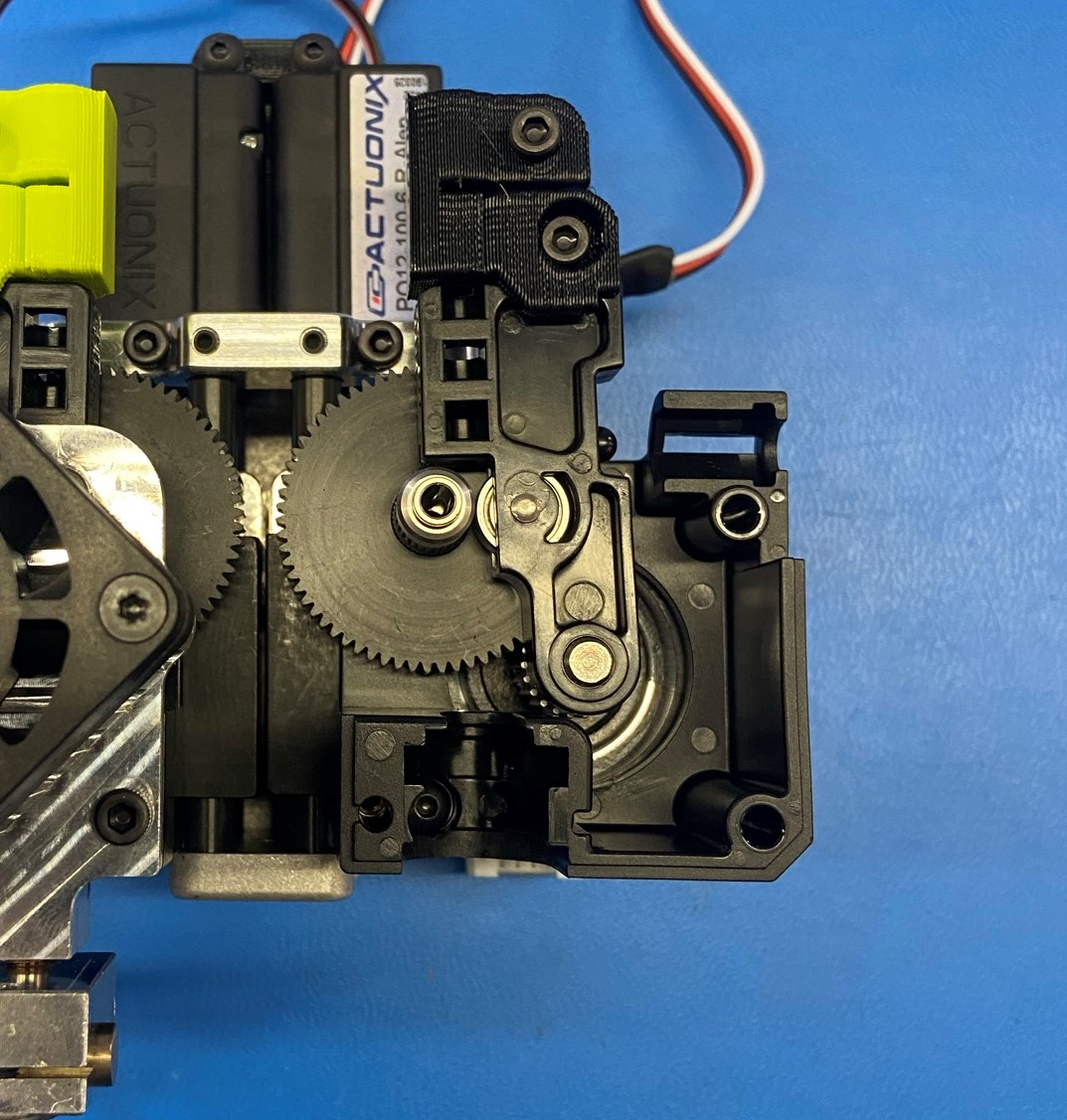
Start by installing the Radial Ball Bearing [HD-MS0446] into the Mirrored body [PP-MP0204]
Next place motor with pinion gear under the motor plate on the actuator sub-assembly
Make sure the motor connector is facing the bottom of the actuator sub-assembly as shown
Then place the mirrored body with bearing over the motor plate and insert the extruded hobb [PP-FP0154] through the bearing on the mirrored body.
Using 1x M3x12 BHCS [HD-BT0146] and 1x M3 Lock washer [HD-WA0027] while holding the motor up, so that the gears mesh together, secure the motor and mirrored body to the actuator sub-assembly.
Torque to 5in lbs
Materials:
Assembly from step 4
1x- [HD-BT0041] - M3x25 SHCS
2x- [HD-BT0043] - M3x35 SHCS
2x- [HD-BT0157] - M3x8 SHCS
1x- [HD-BT0197] - M4 Thumbscrew
4x- [HD-BT0204] - M3x22 FHCS
1x- [HD-MS0430] - Idler Spring
1x- [HD-MS0446] -Radial Ball Bearing
1x- [HD-NT0011] - M4 Nut
1x- [PP-GP0427] - Standard Idler Clamp
1x- [EL-HR0165] - Standard Aero Extruder Harness
1x- [EL-HR0170] - Fan Guard
1x- [PP-FP0158] - Standard Filament Guide
1x- [PP-FP0162] - Standard Idler Lever
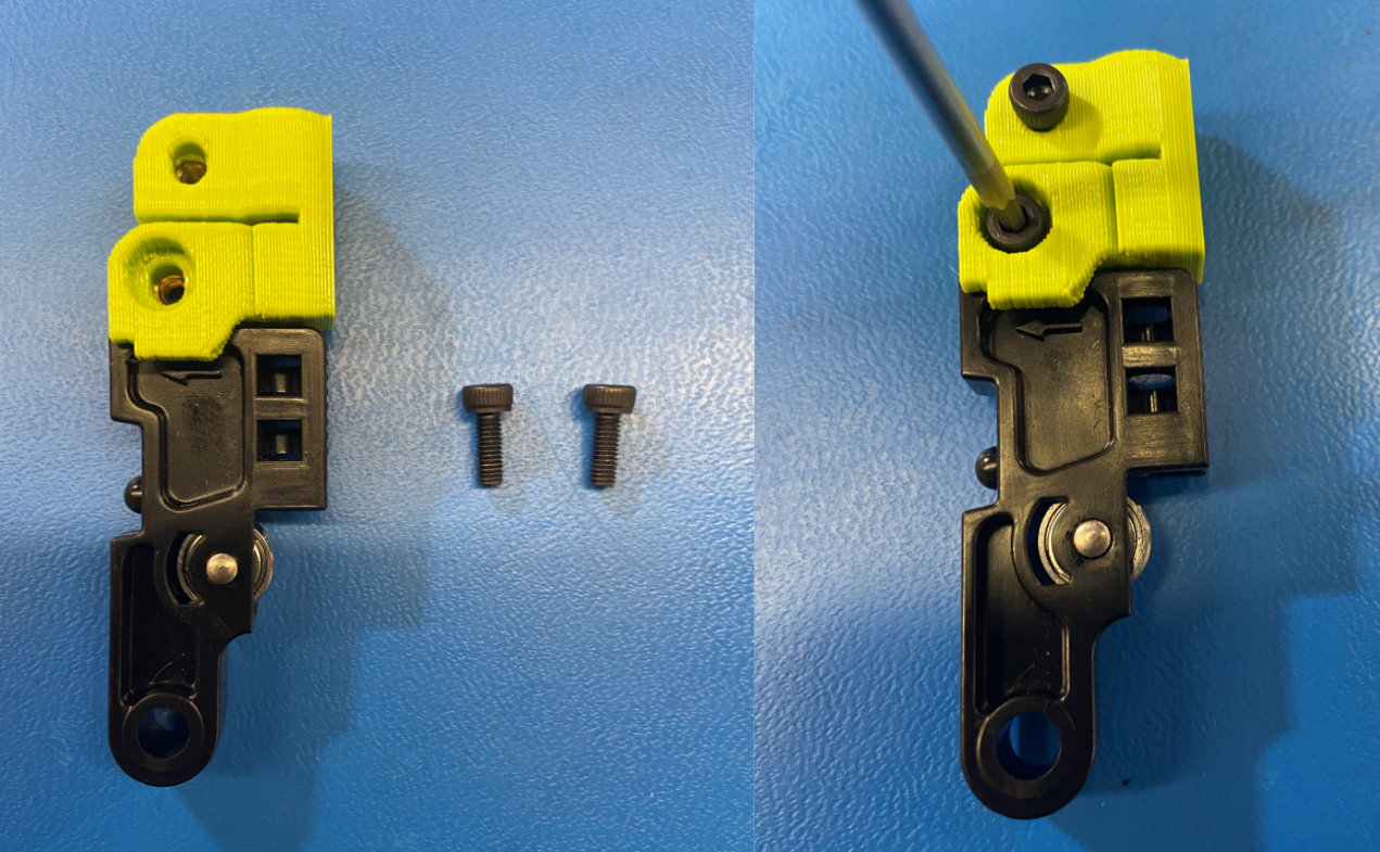
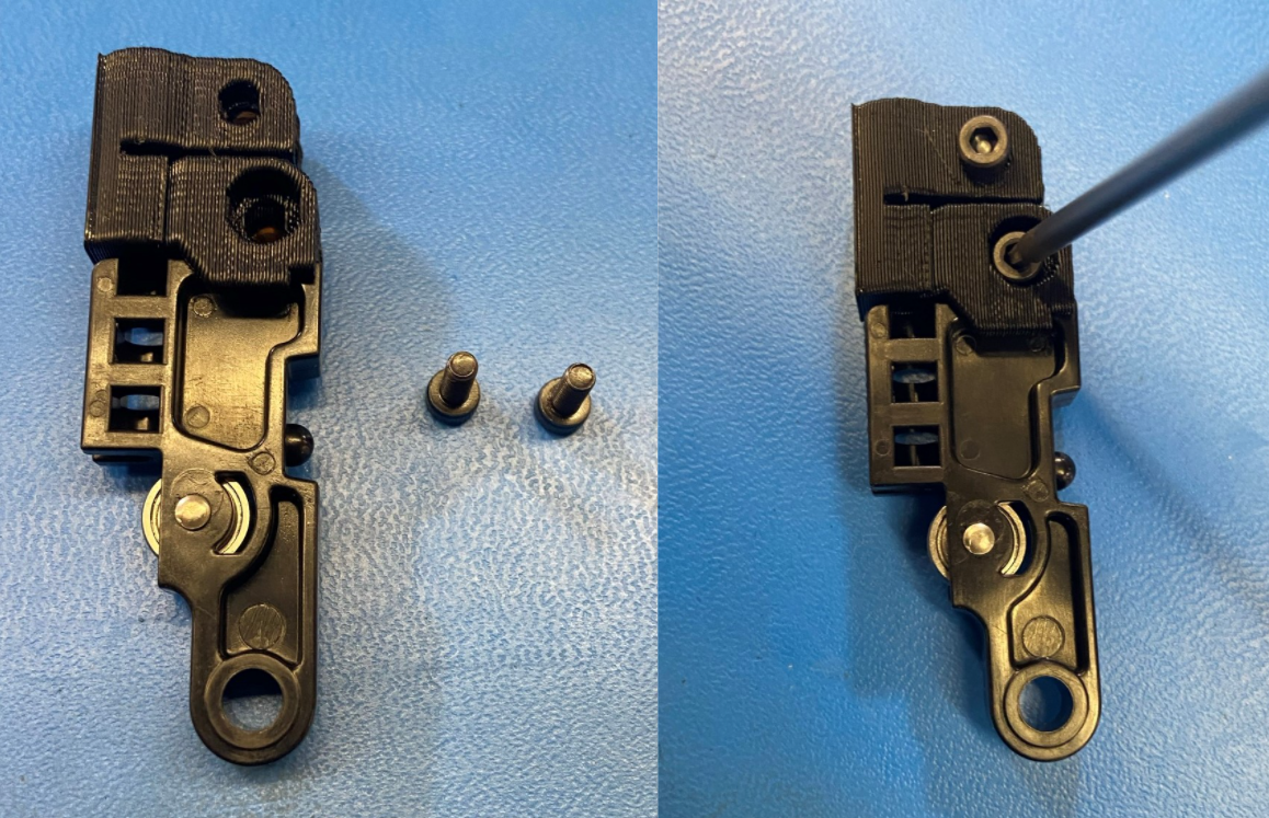
Using 2x M3x8 SHCS [HD-BT0157] attach the Standard Idler Clamp [PP-GP0427] to the Standard Idler Lever [PP-FP0162]
Make sure the hole for the filament is aligned between the idler clamp and the idler lever
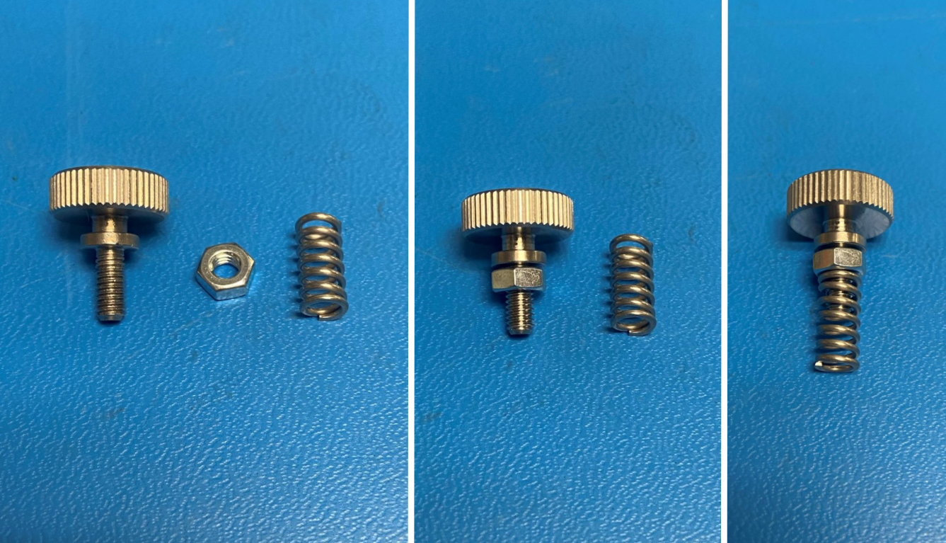
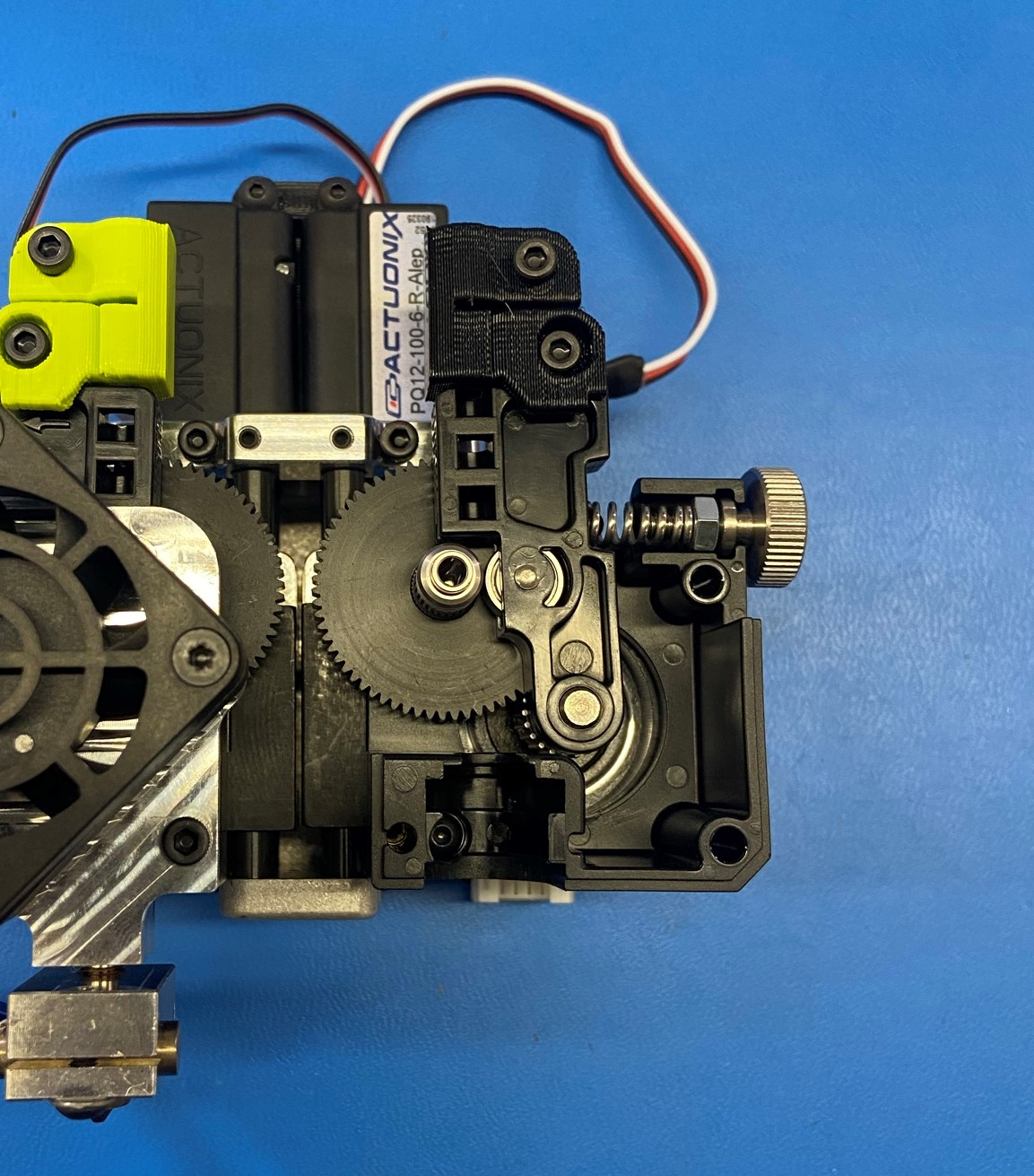
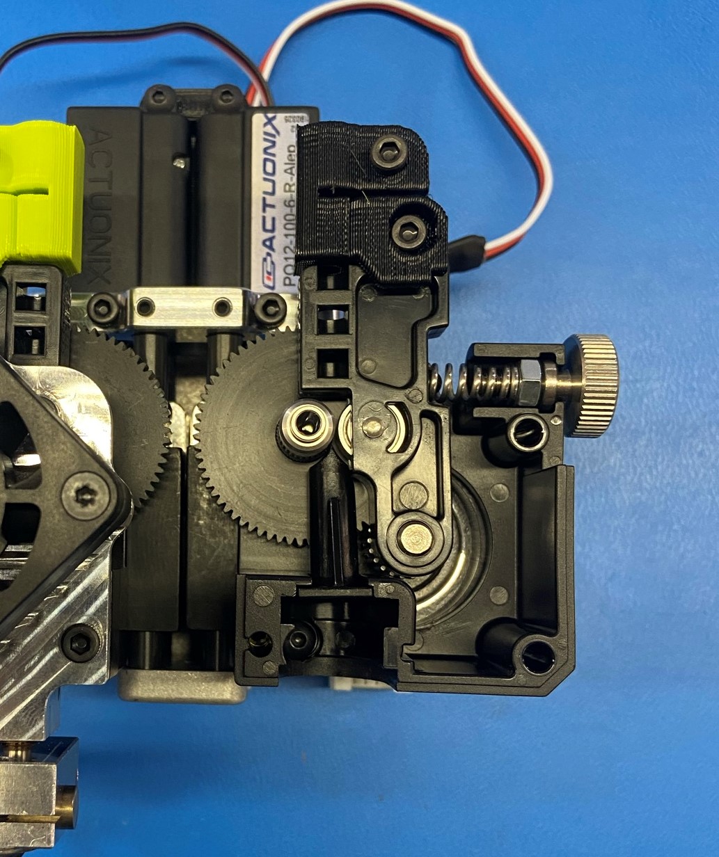
Assemble the thumbscrew tension spring by screwing the M4 nut [HD-NT0011] to the base of the M4 Thumbscrew [HD-BT0197], finish by placing the Idler Spring [HD-MS0430] over the end of the threads.
Apply Super Lube to the thumb screw and thread the nut on and off the thumbscrew a couple of times
Place 1x Radial Ball Bearing [HD-MS0446] in the bearing cavity on the Standard Aero Extruder Harness [EL-HR0165]
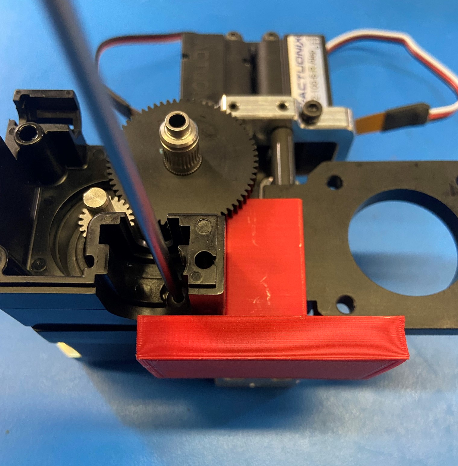
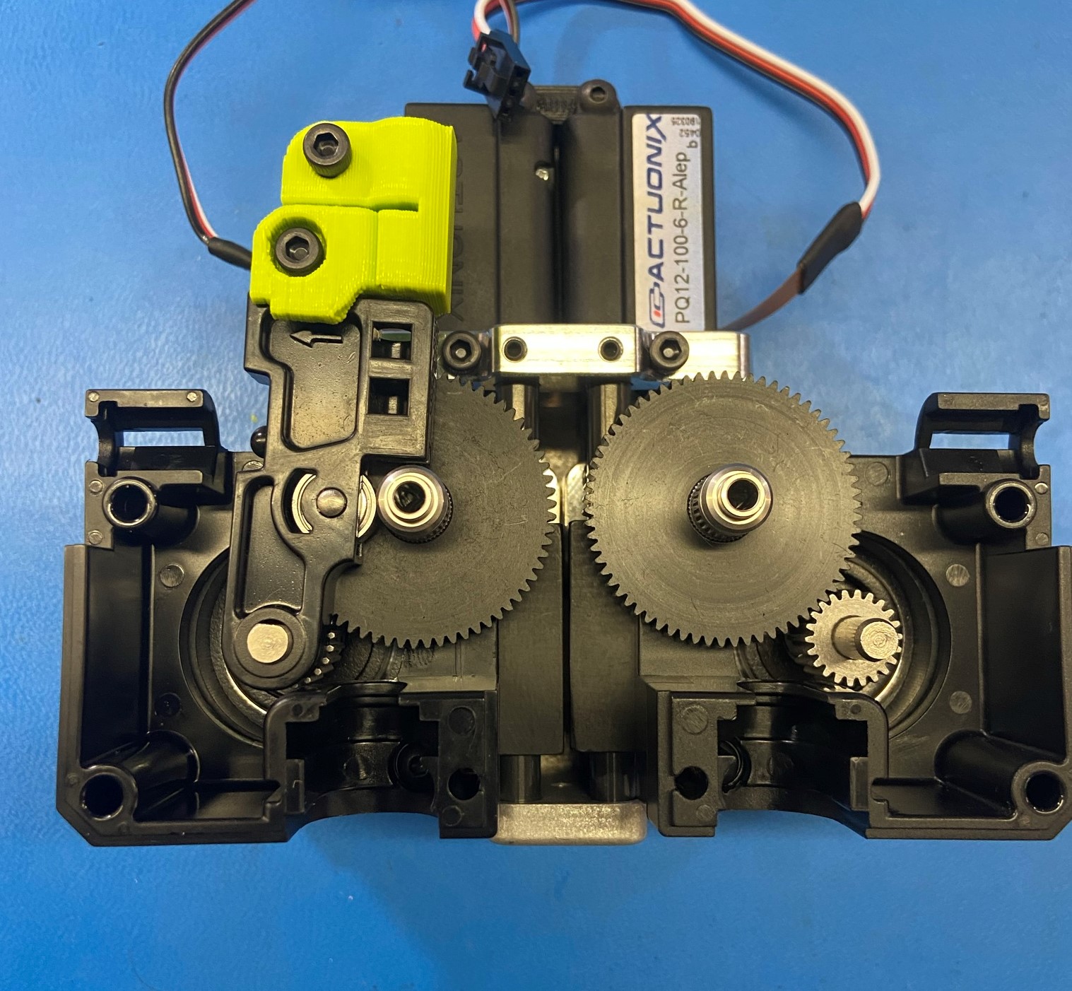
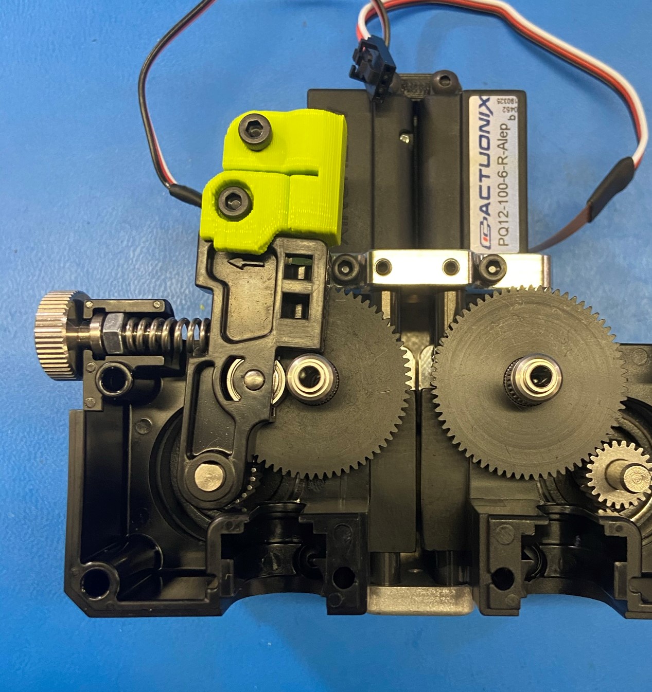
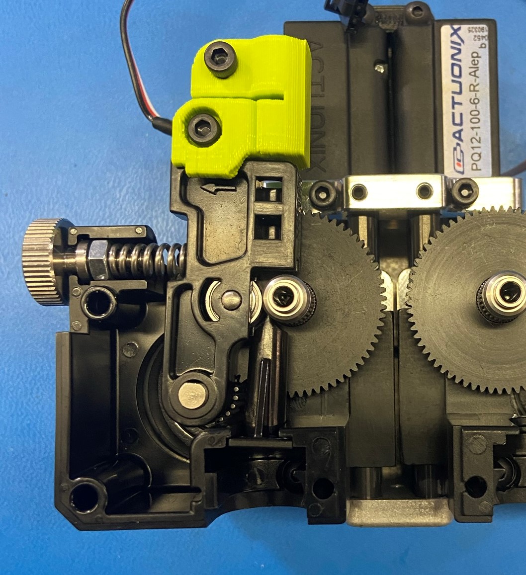
Place the idler lever assembly over the motor shaft, ensure the idler bearing is facing towards the extruded hobb.
Place thumbscrew assembly into the cavity of the standard body, the end of the spring should fit over the nub on the idler lever.
Put the Standard Filament Guide [PP-FP0158] into the cavity below the hobb.
Filament guides should only fit in corresponding extruded body, make sure the bottom of the filament Guide shows 2.85R and not 2.85L
Place the Standard Aero Extruder Harness [EL-HR0165] onto the assembly, make sure the hobb shaft and filament guide are not out of alignment.
Install 1x M3x35 SHCS [HD-BT0043] into the top right hole of the front plate, and Install 1x M3x25 SHCS [HD-BT0041] into the lower right hole. Then using 1x M3x35 SHCS [HD-BT0043] place the ground wire around the screw and fasten the screw into the top left hole making sure the ground wire point outwards.
Torque these to 3in lbs
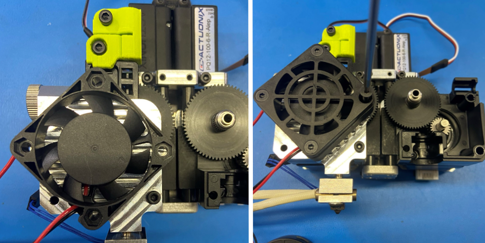
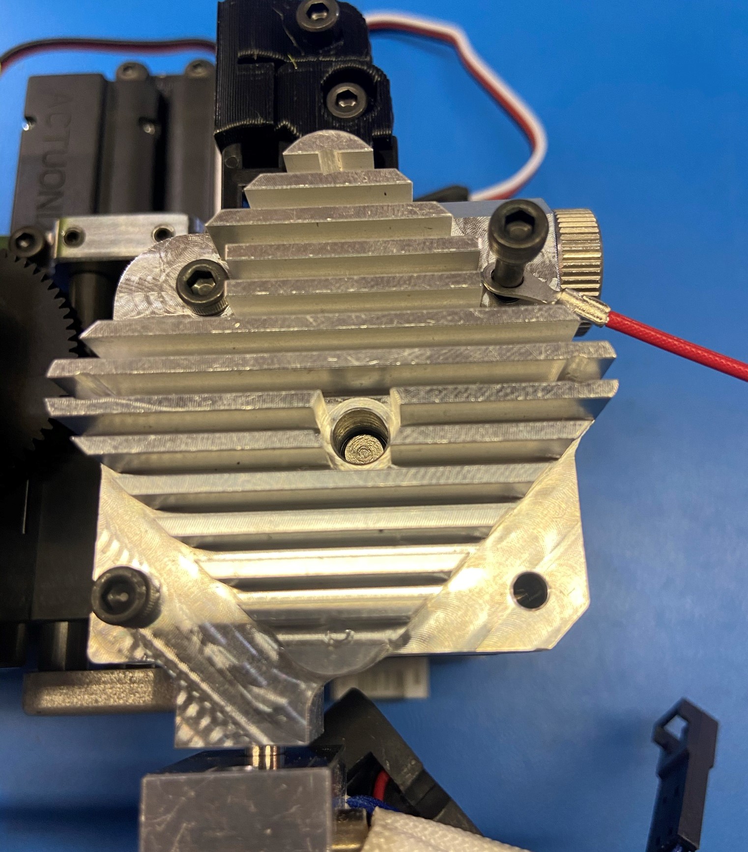
Finish by placing the fan, fan guard [EL-HR0170] over the Standard Aero Extruder Harness, and secure using 4x M3x22 FHCS [HD-BT0204].
Be sure the fan is in the correct orientation. The label should not be visible.


Materials:
Assembly from step 5
1x- [HD-BT0041] - M3x25 SHCS
2x- [HD-BT0043] - M3x35 SHCS
2x- [HD-BT0157] - M3x8 SHCS
1x- [HD-BT0197] - M4 Thumbscrew
4x- [HD-BT0204] - M3x22 FHCS
1x- [HD-MS0430] - Idler Spring
1x- [HD-MS0446] -Radial Ball Bearing
1x- [HD-NT0011] - M4 Nut
1x- [PP-GP0428] - Mirrored Idler Clamp
1x- [EL-HR0166] - Mirrored Aero Extruder Harness
1x- [EL-HR0170] - Fan Guard
1x- [PP-FP0135] - Mirrored Idler Lever
1x- [PP-FP0136] - Mirrored Filament Guide
Using 2x M3x8 SHCS [HD-BT0157] attach the Mirrored Idler Clamp [PP-GP0428] to the Mirrored Idler Lever [PP-FP0135]
Make sure the hole for the filament is aligned between the idler clamp and the idler lever
Assemble the thumbscrew tension spring by screwing the M4 nut [HD-NT0011] to the base of the M4 Thumbscrew [HD-BT0197], finish by placing the Idler Spring [HD-MS0430] over the end of the threads.
Apply Super Lube to the thumb screw and thread the nut on and off the thumbscrew a couple of times
Place 1x Radial Ball Bearing [HD-MS0446] in the bearing cavity on the Mirrored Aero Extruder Harness [EL-HR0166]
Place the idler lever assembly over the motor shaft, ensure the idler bearing is facing towards the extruded hobb.
Place thumbscrew assembly into the cavity of the mirrored body, the end of the spring should fit over the nub on the idler lever.
Put the Mirrored Filament Guide [PP-FP0136] into the cavity below the hobb.
Filament guides should only fit in corresponding extruded body, make sure the bottom of the filament Guide shows 2.85L and not 2.85R
Place the Mirrored Aero Extruder Harness [EL-HR0166] onto the assembly, make sure the hobb shaft and filament guide are not out of alignment.
Install 1x M3x35 SHCS [HD-BT0043] into the top left hole of the front plate, and Install 1x M3x25 SHCS [HD-BT0041] into the lower left hole. Then using 1x M3x35 SHCS [HD-BT0043] place the ground wire around the screw and fasten the screw into the top right hole making sure the ground wire point outwards.
Torque these to 3in lbs
Finish by placing the fan, fan guard [EL-HR0170] over the Mirrored Aero Extruder Harness, and secure using 4x M3x22 FHCS [HD-BT0204].
Be sure the fan is in the correct orientation. The label should not be visible.


Materials:
Assembly from step 6
2x- [HD-BT0042] - M3x30 SHCS
2x- [HD-BT0043] - M3x35 SHCS
1x- [PP-GP0470] - Left Cable Channel
1x- [PP-GP0471] - Right Cable Channel
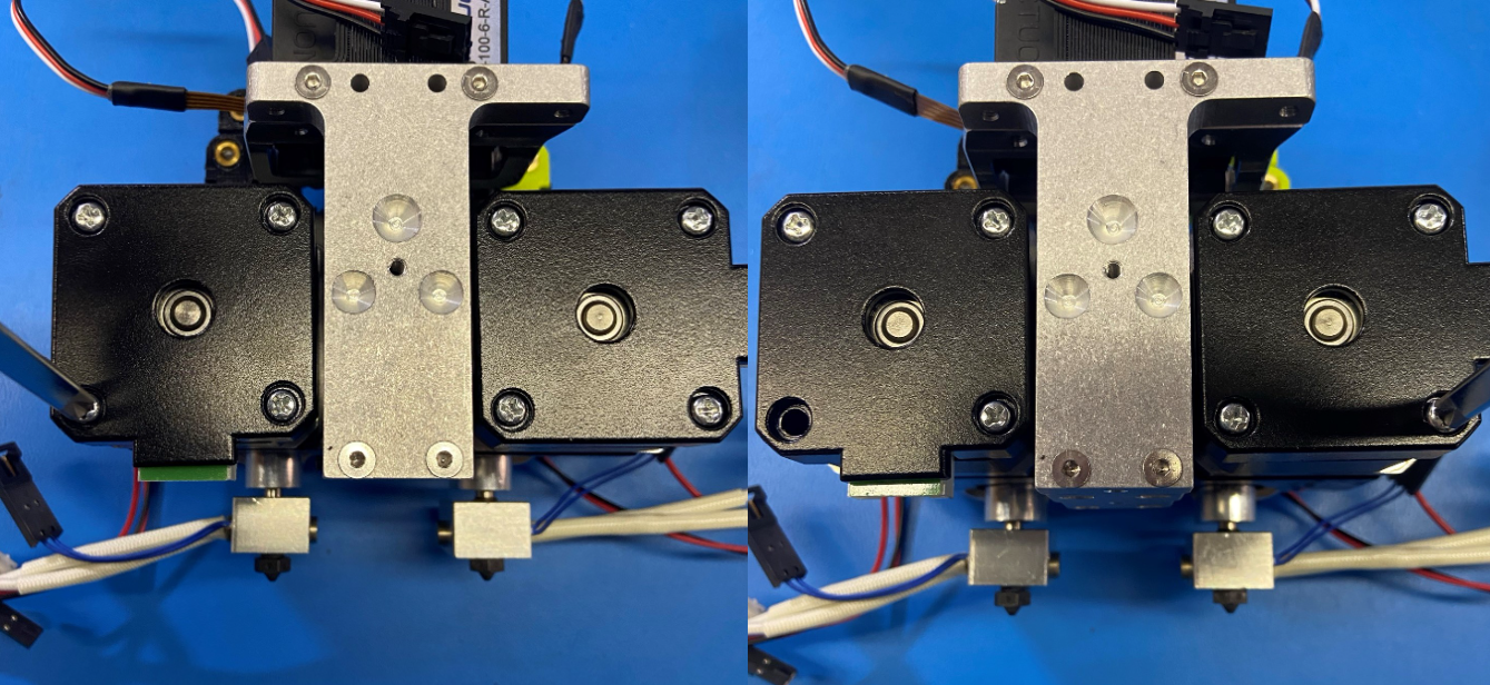
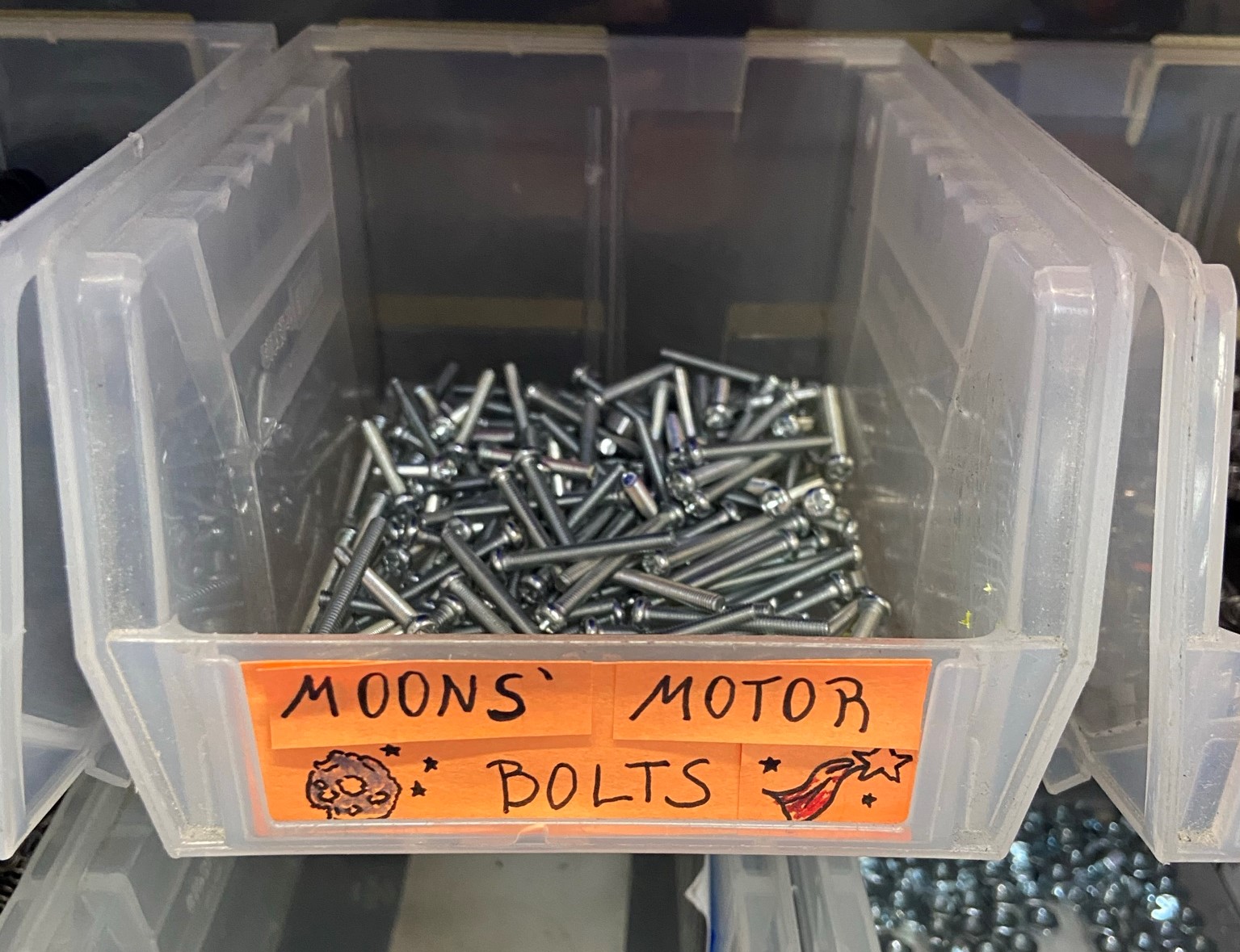
Using a Phillips head screwdriver, remove the outer bottom screw from both motors. (Place Moons Motor bolt in designated bin)
Start with the Standard Aero Extruder Harness (Left side)
First make sure the wire sheathing is 50 mm long if it's long then trim down to 50mm
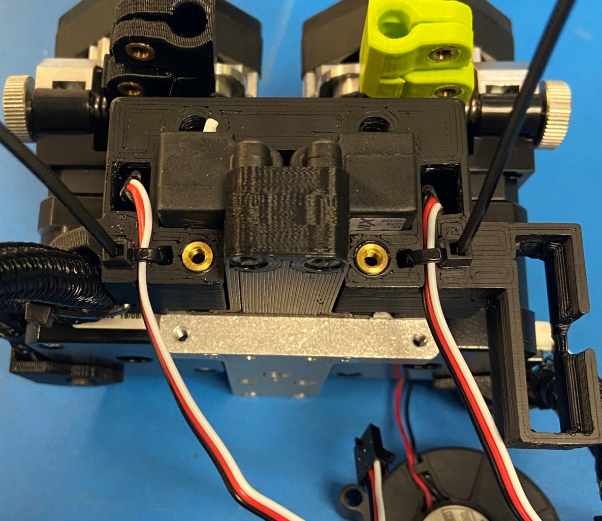
Connect the two wires for the thermistor and slide it in the Left Cable Channel [PP-GP0470]
Then take the two white hot end wires and place them in the left cable channel next to the thermistor connector
Take the rest of the wires except for the motor wire and place them in the cable channel
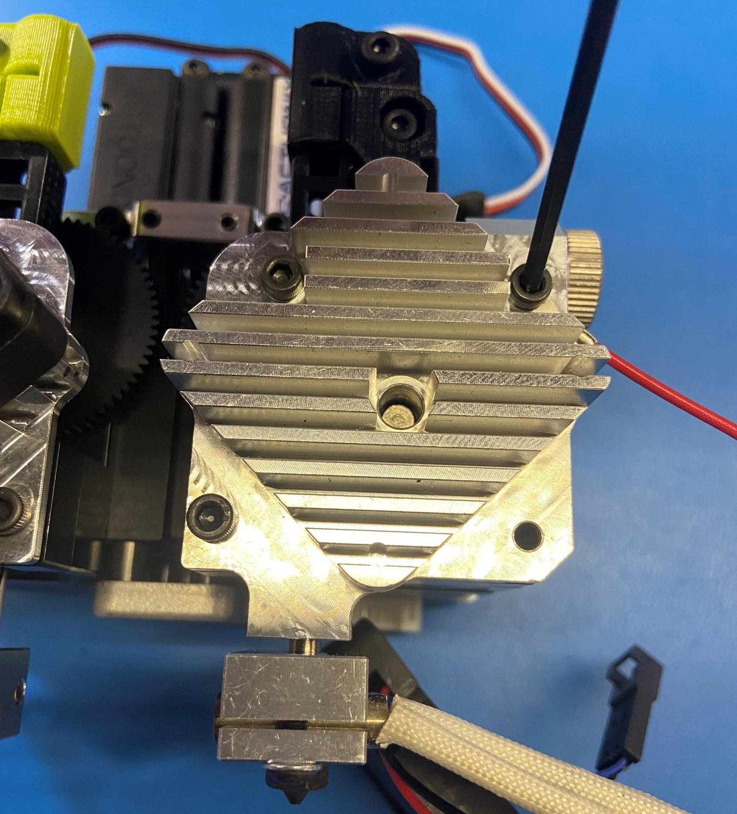
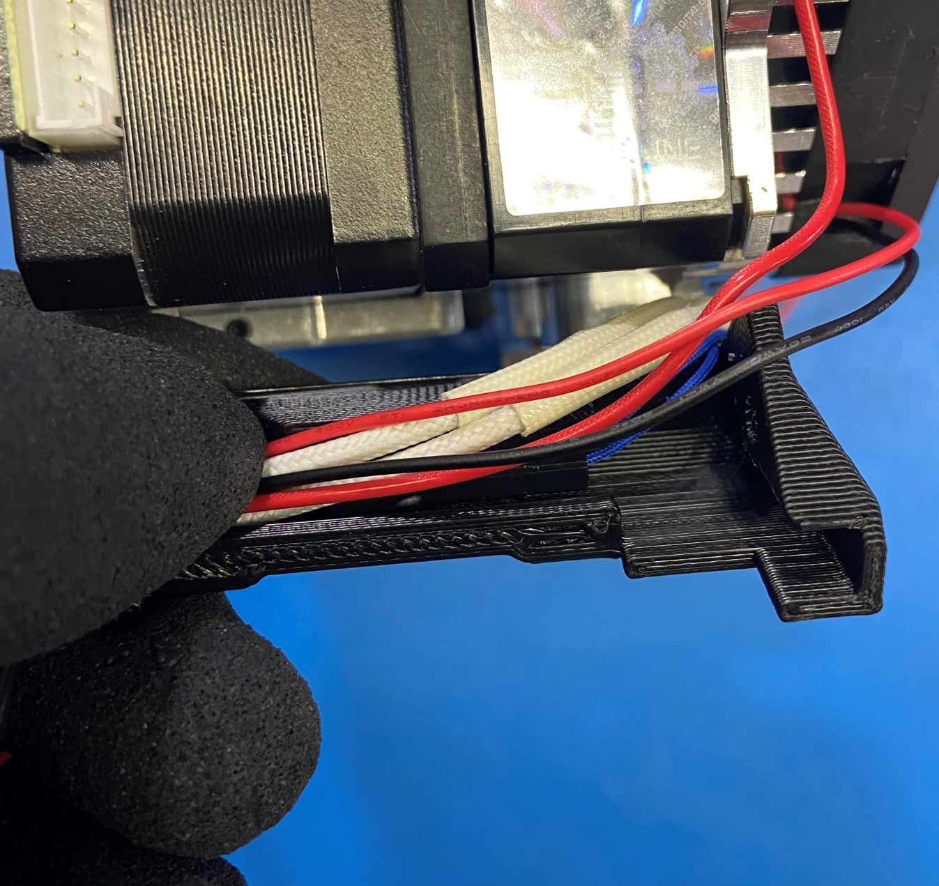
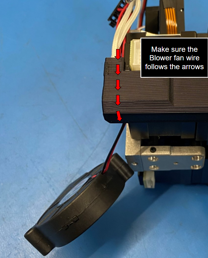
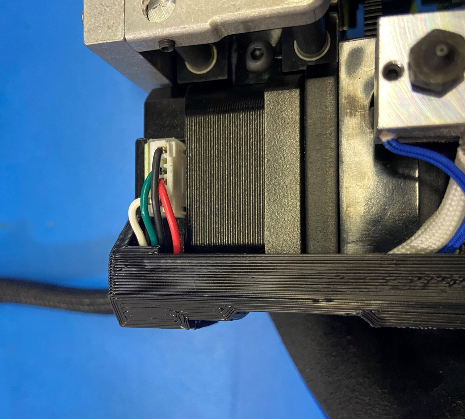
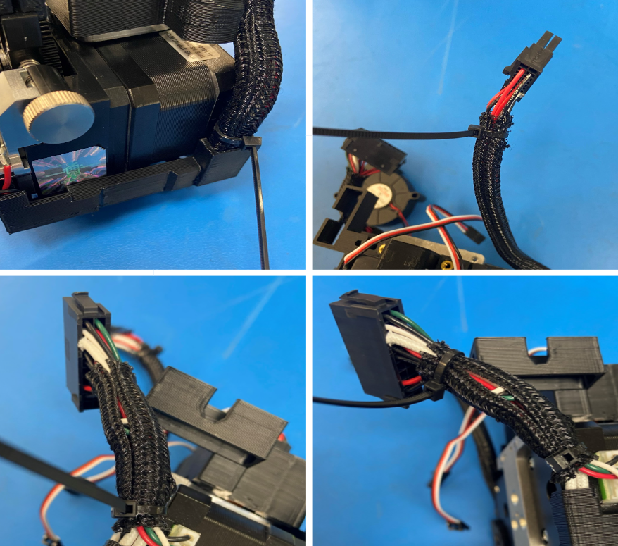
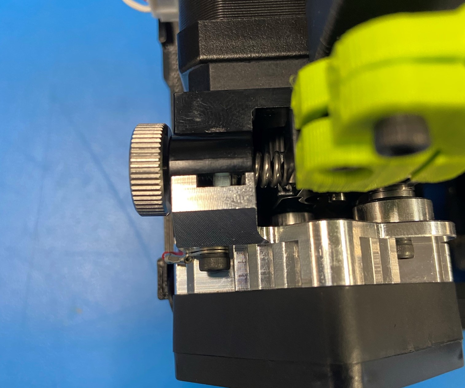
Make sure the blower fan wire follows the side of the cable channel [reference#1]
Then keeping all the wires in the cable channel, secure both end using 1x M3x30 SHCS [HD-BT0042] and 1x M3x35 SHCS [HD-BT0043], use the M3x30 SHCS on the motor side and the M3x35 SHCS one the side with the fan. Do not Over-Tighten or cable channel may break
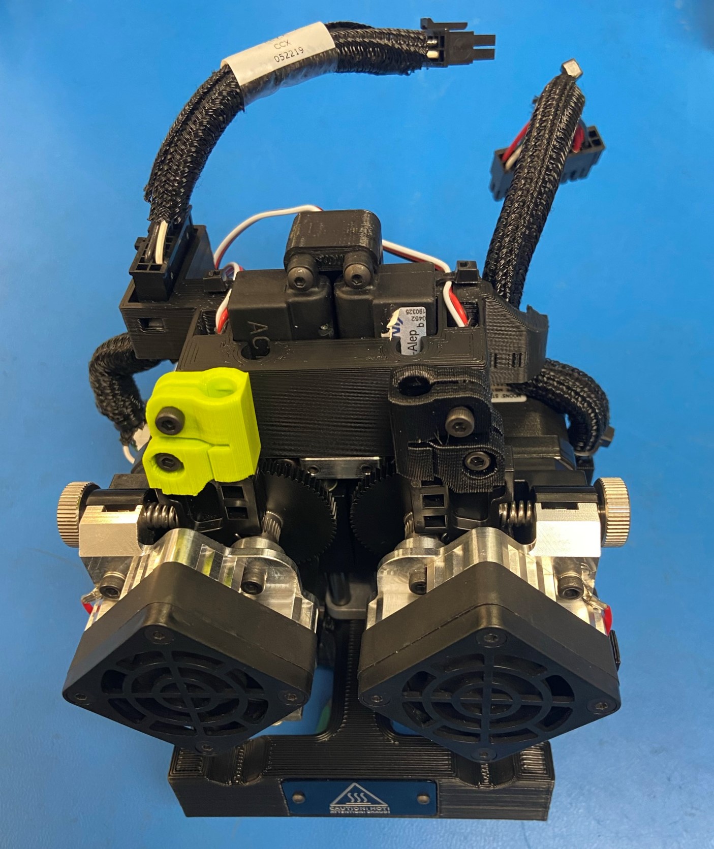
Check work, making sure the wires are fully inside the cable channel and that the cable channel is parallel with the toolhead
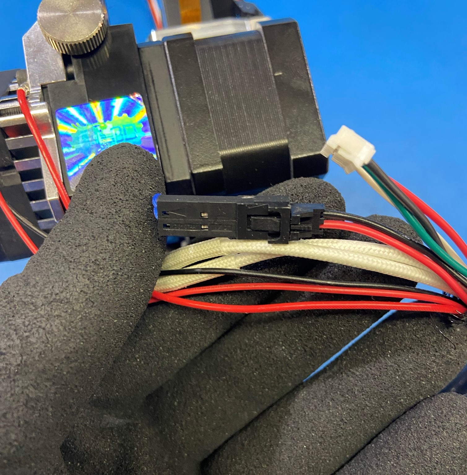
Wrap the motor wire around all of the other wires two time then plug it into the motor
Start on the Mirrored Aero Extruder Hardness
Connect the two wires for the thermistor and slide it in the Right Cable Channel [PP-GP0471]
Then take the two white hot end wires and place them in the right cable channel next to the thermistor connector
Take the rest of the wires place them in the cable channel
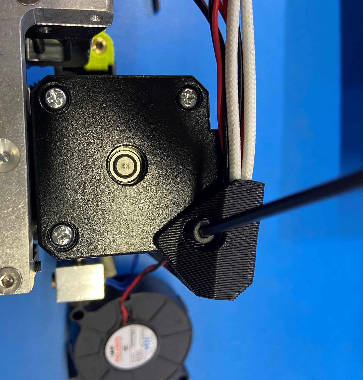
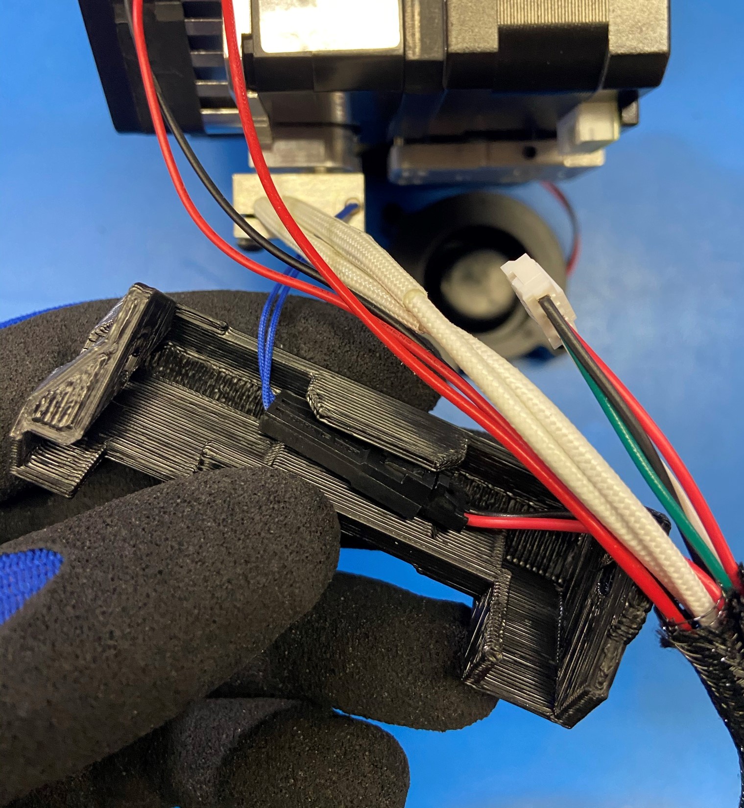
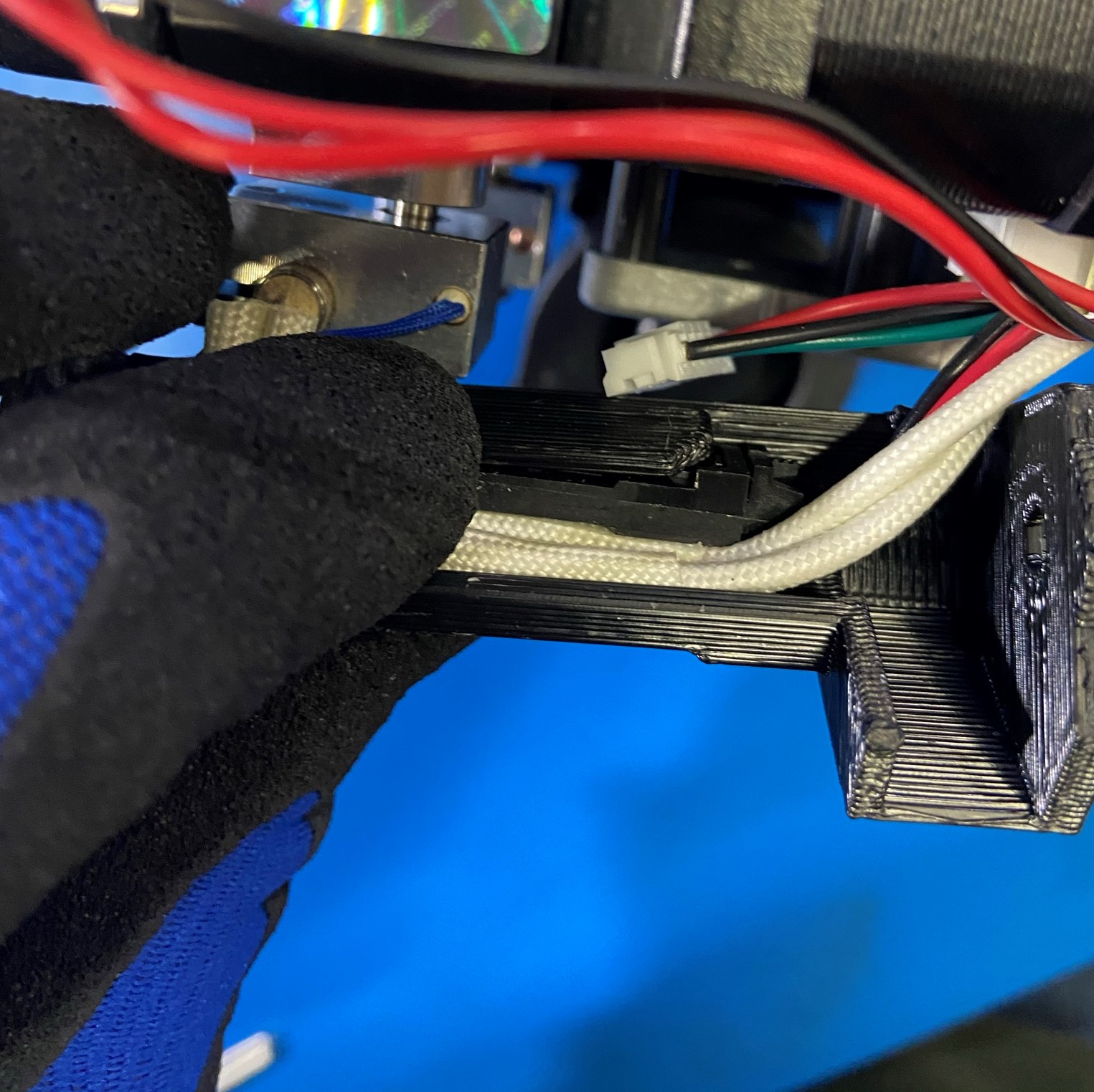
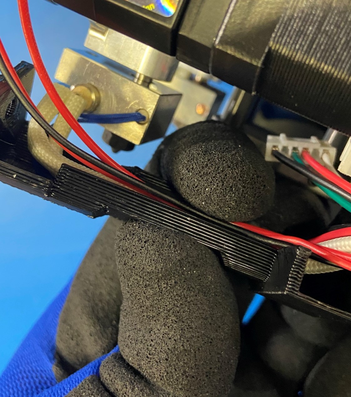
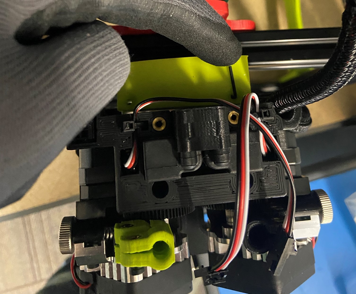
Make sure the motor wire follows the side of the cable channel [reference#2]
Then keeping all the wires in the cable channel, secure both end using 1x M3x30 SHCS [HD-BT0042] and 1x M3x35 SHCS [HD-BT0043], use the M3x30 SHCS on the rear motor side and the M3x35 SHCS on the front side with the fan. Do not Over-Tighten or cable channel may break
Check work, making sure the wires are fully inside the cable channel and that the cable channel is parallel with the toolhead


Materials:
Assembly from step 7
1x- [PP-GP0420] - Actuator Cover
2x- [HD-BT0128] - M3x6 FHCS
7x- [HD-MS0058] - Zip Tie
1x- [EL-HR0145] - E1 Extension harness
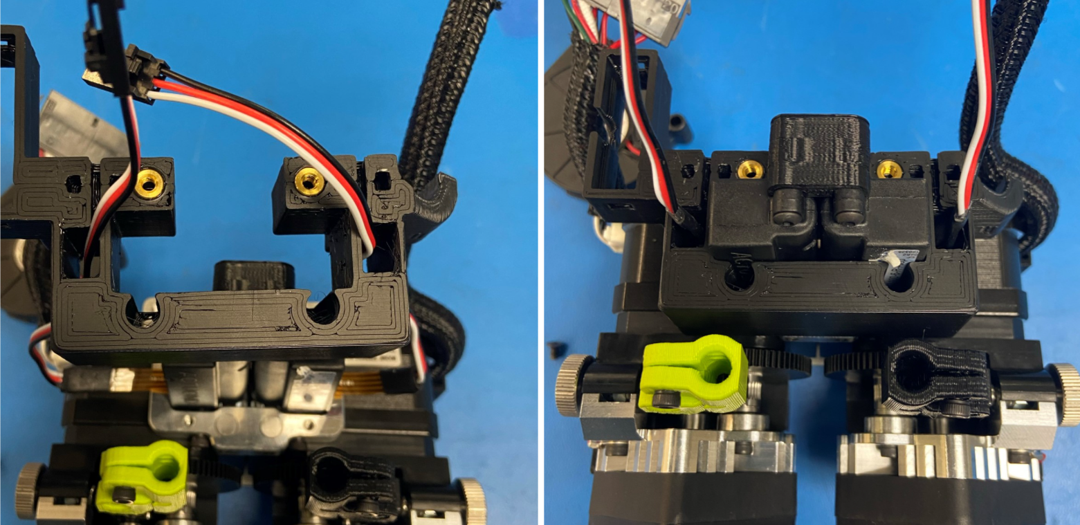
Feed the two actuator wires through the Actuator Cover [PP-GP0420] then slide the actuator cover over the actuators, make sure not to pinch the fragile ribbon cable. Fasten the actuator cover to the assembly using 2x M3x6 FHCS [HD-BT0128]
Using 4x Zip Ties [HD-MS0058] secure the sheathing around the two Aero Extruder harnesses. Use two zip ties for both wires one and the top of the sheathing and one at the bottom.
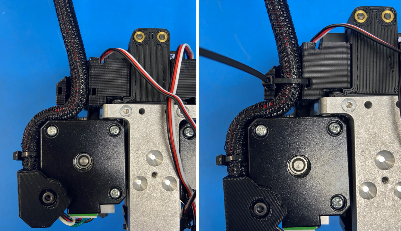
Route the mirrored harness under the actuator cover, so it's in between the actuator cover and the motor, then route it through the channel on the actuator cover and secure with a zip tie with the head facing outwards.
Using 2x zip ties, secure the two actuator wires to the actuator cover making sure the zip tie heads are facing outwards.
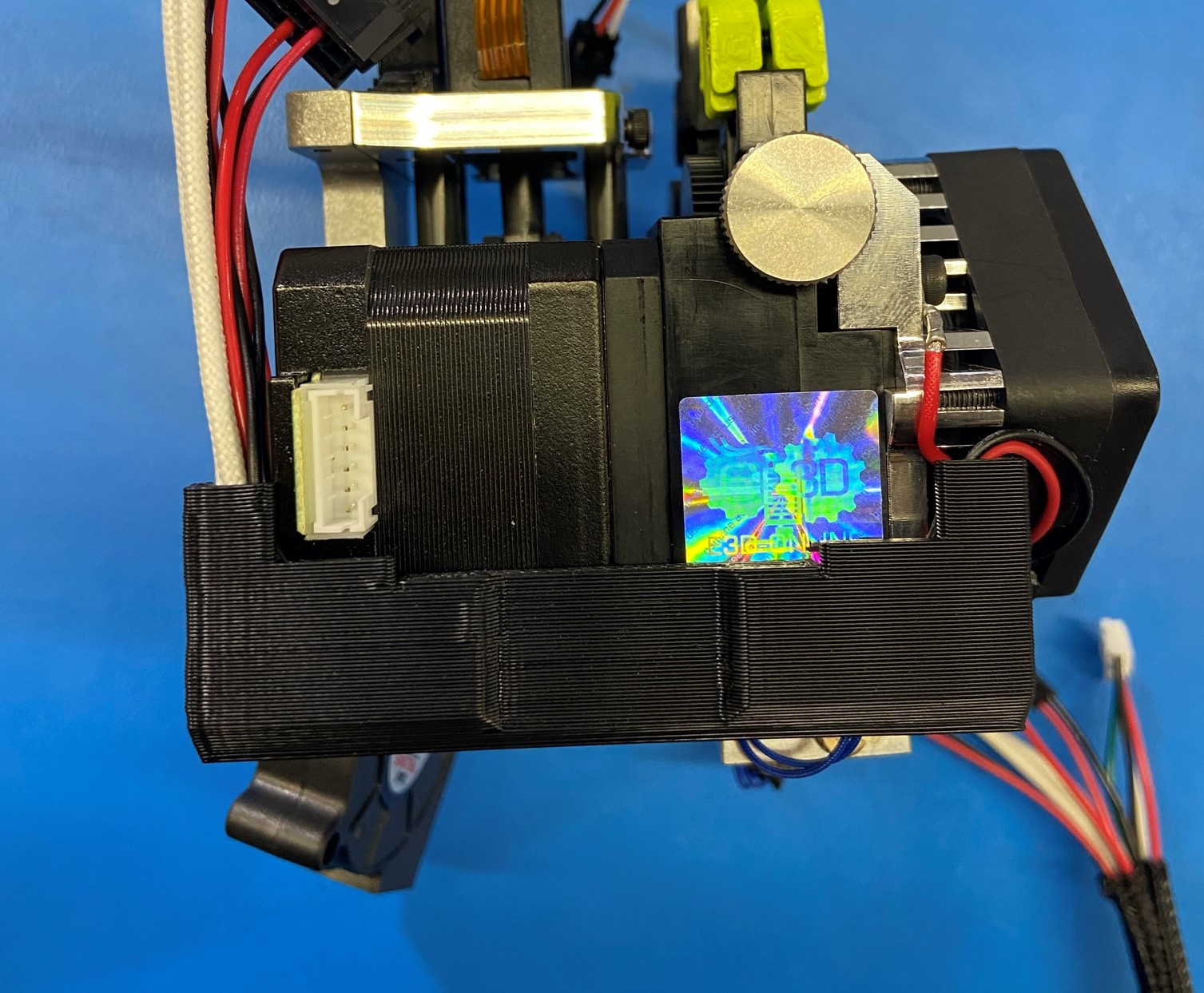
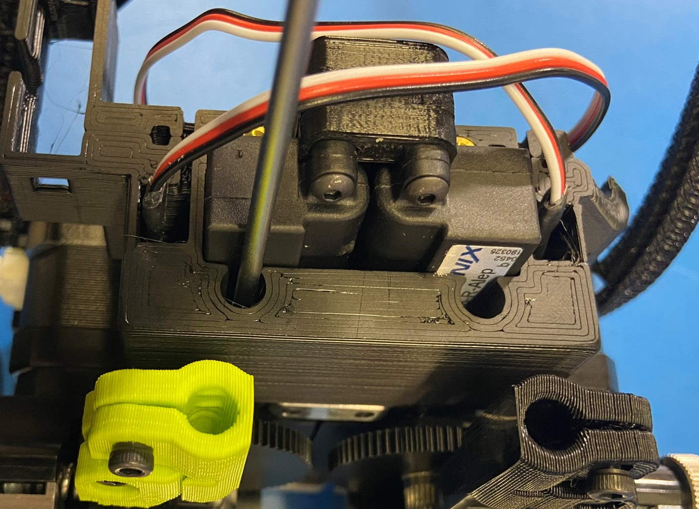
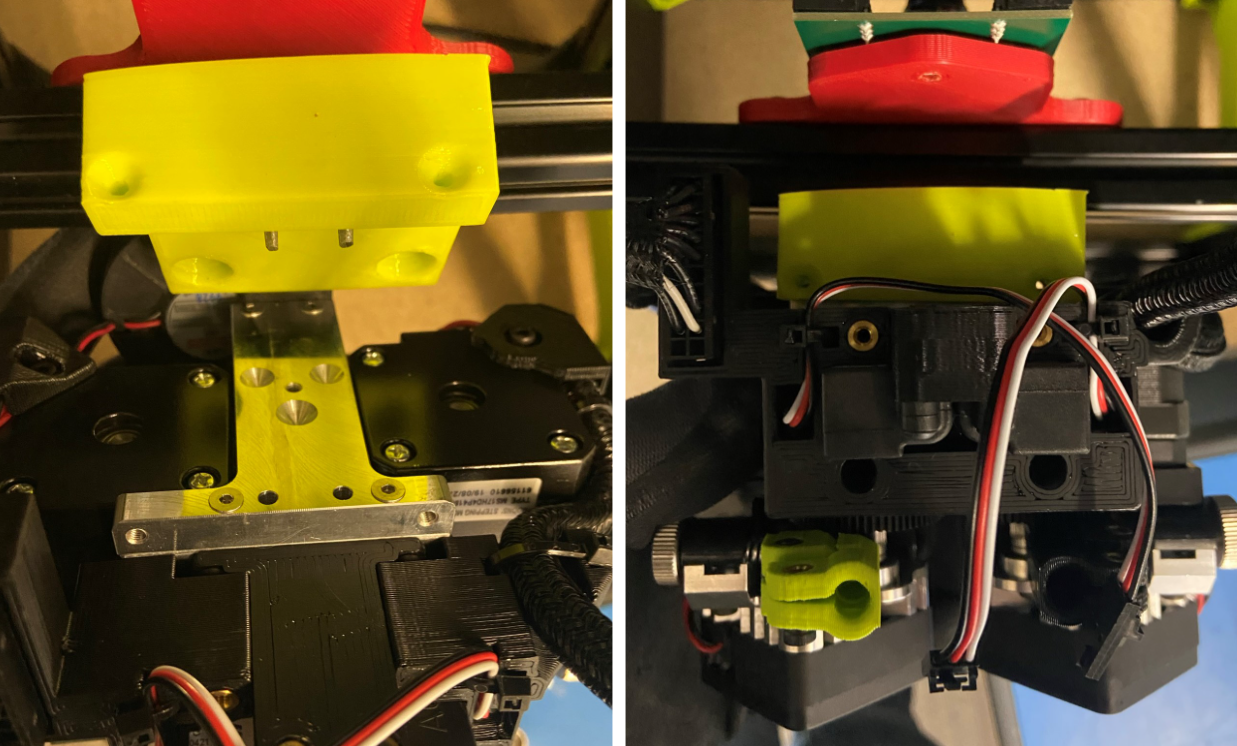
Extend the actuator on the left side as shown in [reference#3]
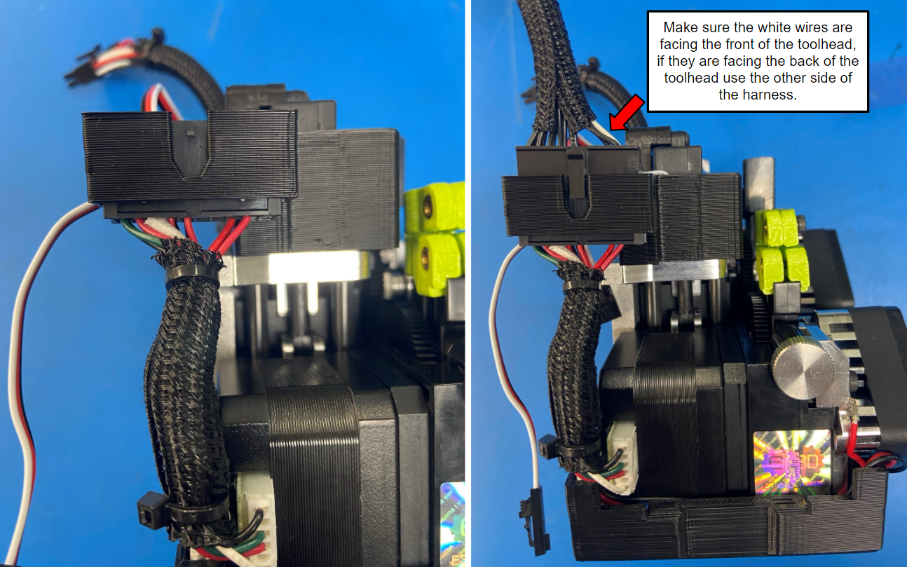
Take the end of the standard aero extruder harness and slide it through the actuator cover making sure the two tabs on the side snap into place, then take the E1 Extension Harness [EL-HR0145] and connect it to the standard aero extruder harness.
Make sure the white wires on the extension harness are facing the front of the toolhead.

Materials: Assembly for step 8
1x- [PP-GP0419] Blower Shroud
1x- [DC-LB0175] Caution Hot Tag
2x- [HD-BT0235] M2x0.4 BHCS
2x- [HD-BT0128] M3x6 FHCS
1x- [HD-BT0171] M3x20 BHCS
1x- [HD-WA0038] M3 Washer
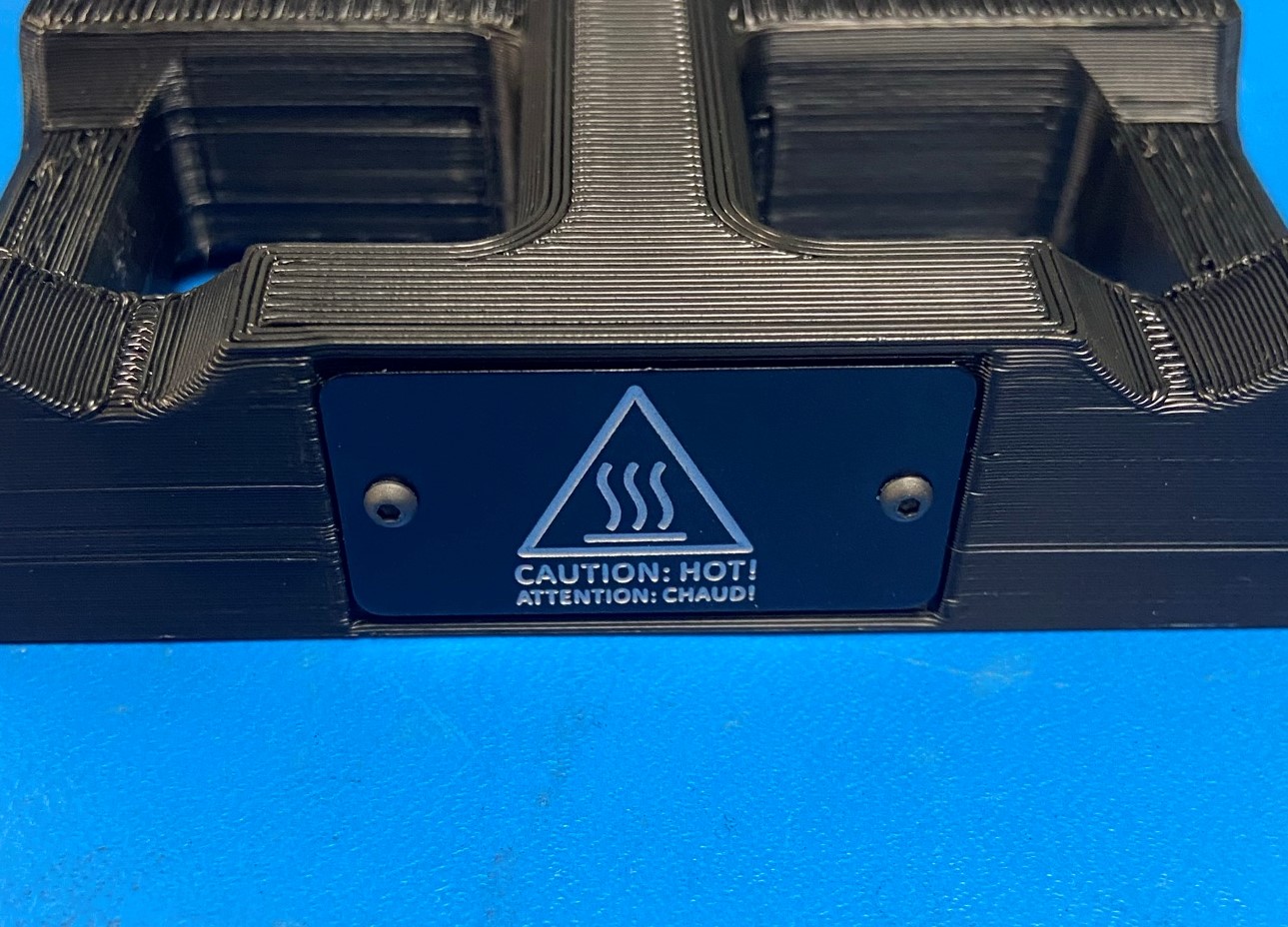
Using 2x M2x0.4 BHCS [HD-BT0235], 1x Caution Hot Tag [DC-LB0175], and 1x Blower Shroud [PP-GP0419] attach the caution hot tag to the blower shroud making sure the bottom of the tag is on the same side that has the flat edge.
Attach the blower shroud with the hot tag to the assembly from step 8 using 2x M3x6 FHCS [HD-BT0128]
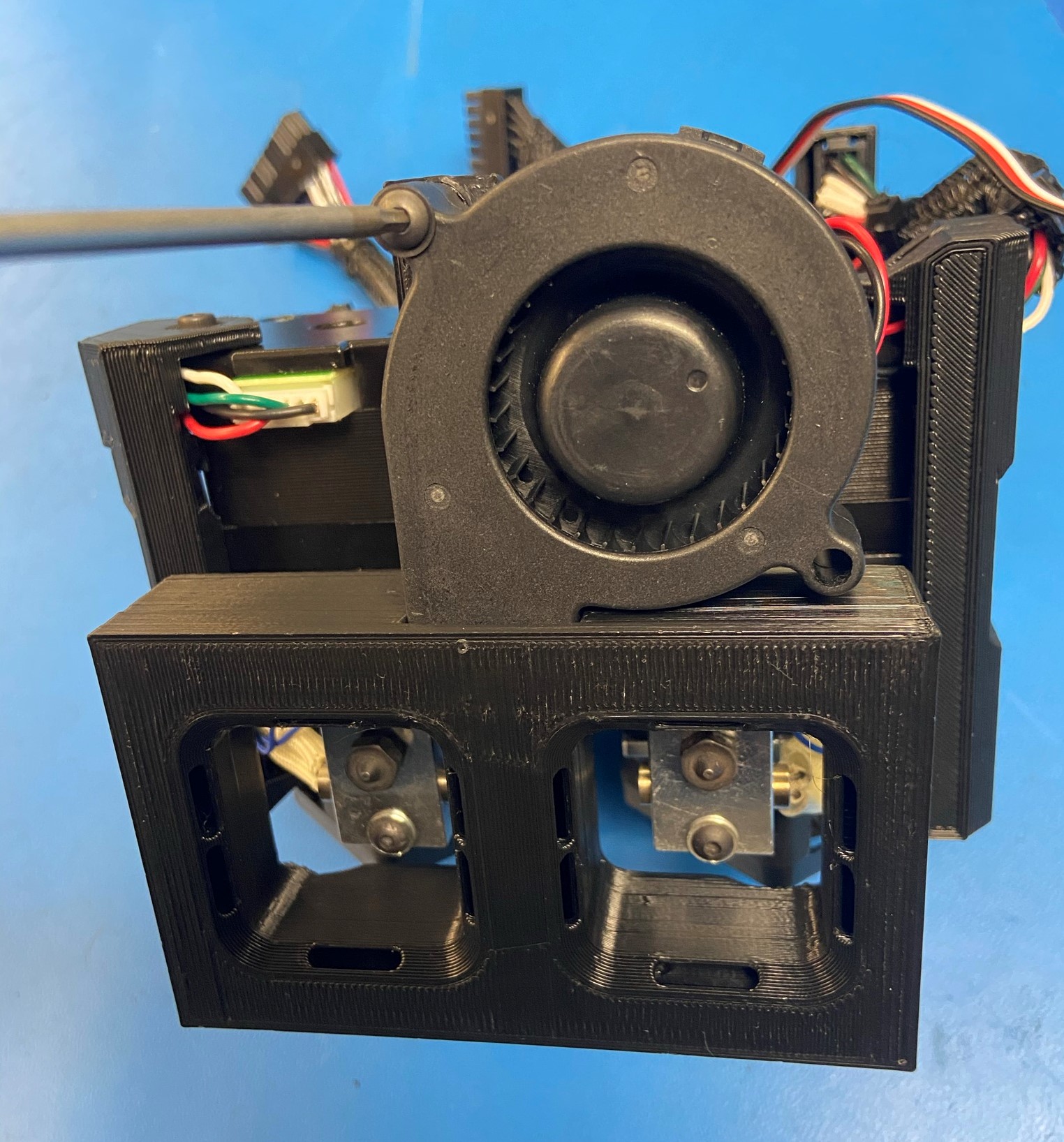
Using 1x M3x20 BHCS [HD-BT0171] with 1x M3 Washer [HD-WA0038] attach the fan to the blower shroud
Turn the idler spring compression thumbscrew [HD-BT0197] until the idler spring compression nut is in the middle of the adjustment window.
Repeat with other side

Check for the following:
-No pinched wires
-No cross threaded/rounded screws
-Hot tag is flush with the printed part
-Motor wires fully plugged in
-Ground wires tight to hot end
-Tight zipties
-Trimmed zipties
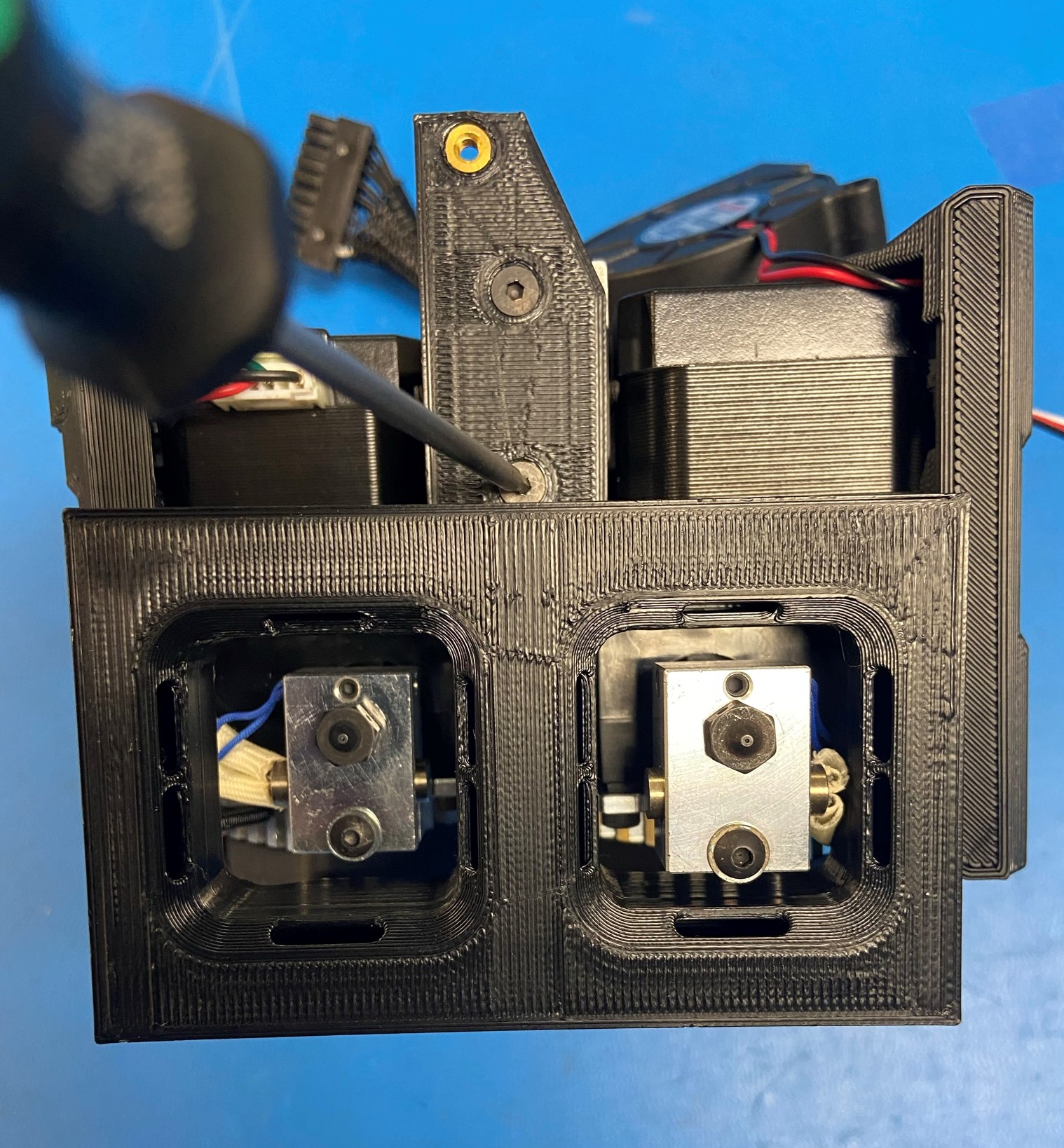
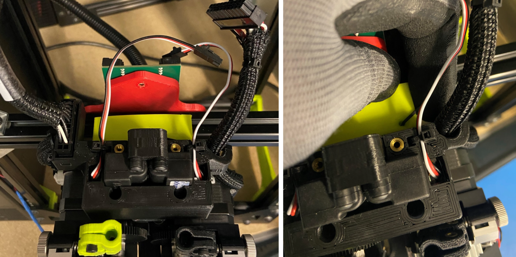
Remove the Hex Key from the text bar and align the two prongs on the test bar with the two holes on the back plate of the actuators.
Then place the Hex Key in either the left or right hole to secure the tool head to the test bar
Note: You have to wiggle the Hex Key around before you can slide it all the way down
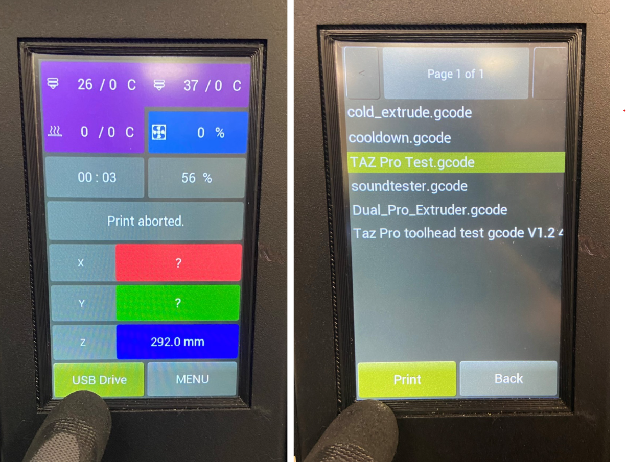
Power on the test stand
Are both heat sink fans running? If not the unit has failed.
Navigate to the TAZ Pro Test.gcode in the USB Drive menu and select "Print"
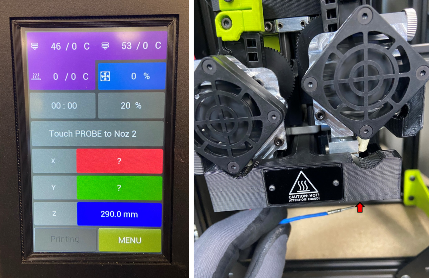
Grab the probe and touch it to the left nozzle
Wait for the tool head to switch to the right nozzle then Touch the probe to the right nozzle
While switching extruders, watch the blower shroud and both movements to ensure no interference or binding occurs.
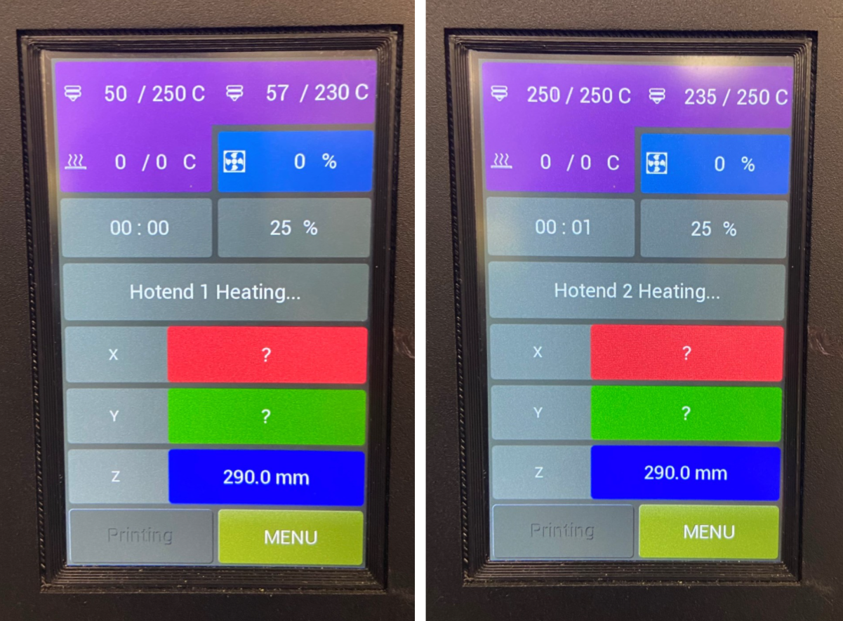
You must observe the following:
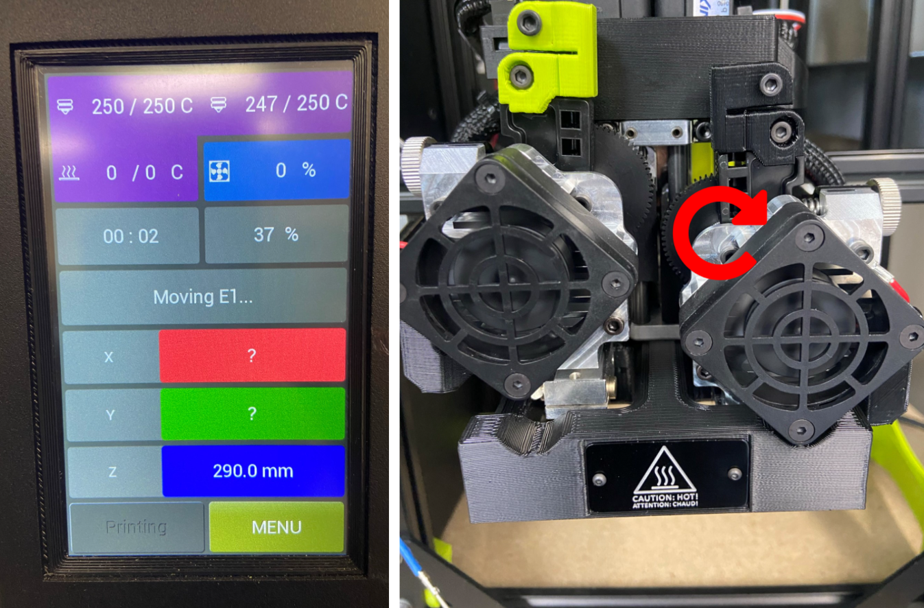
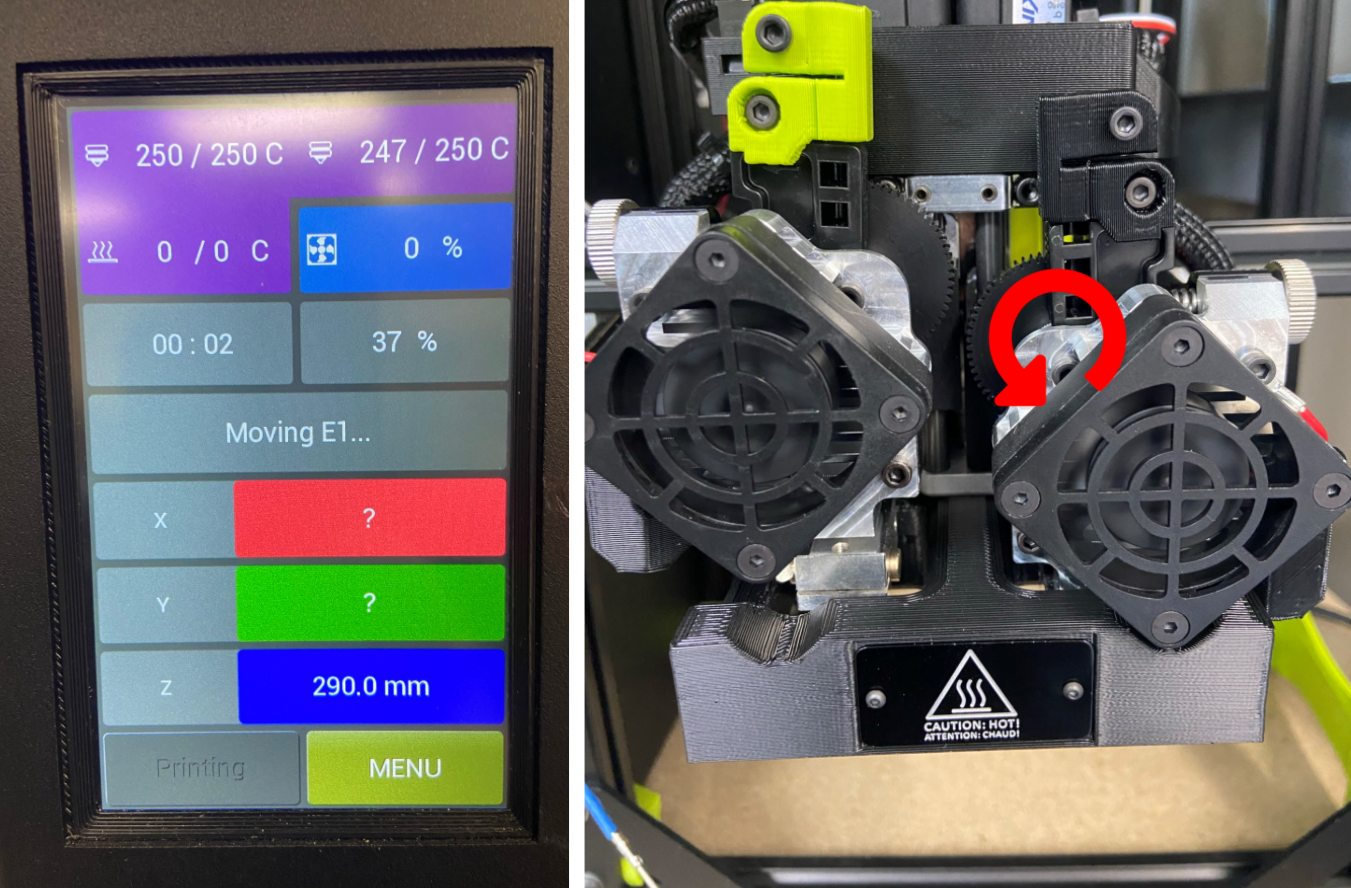
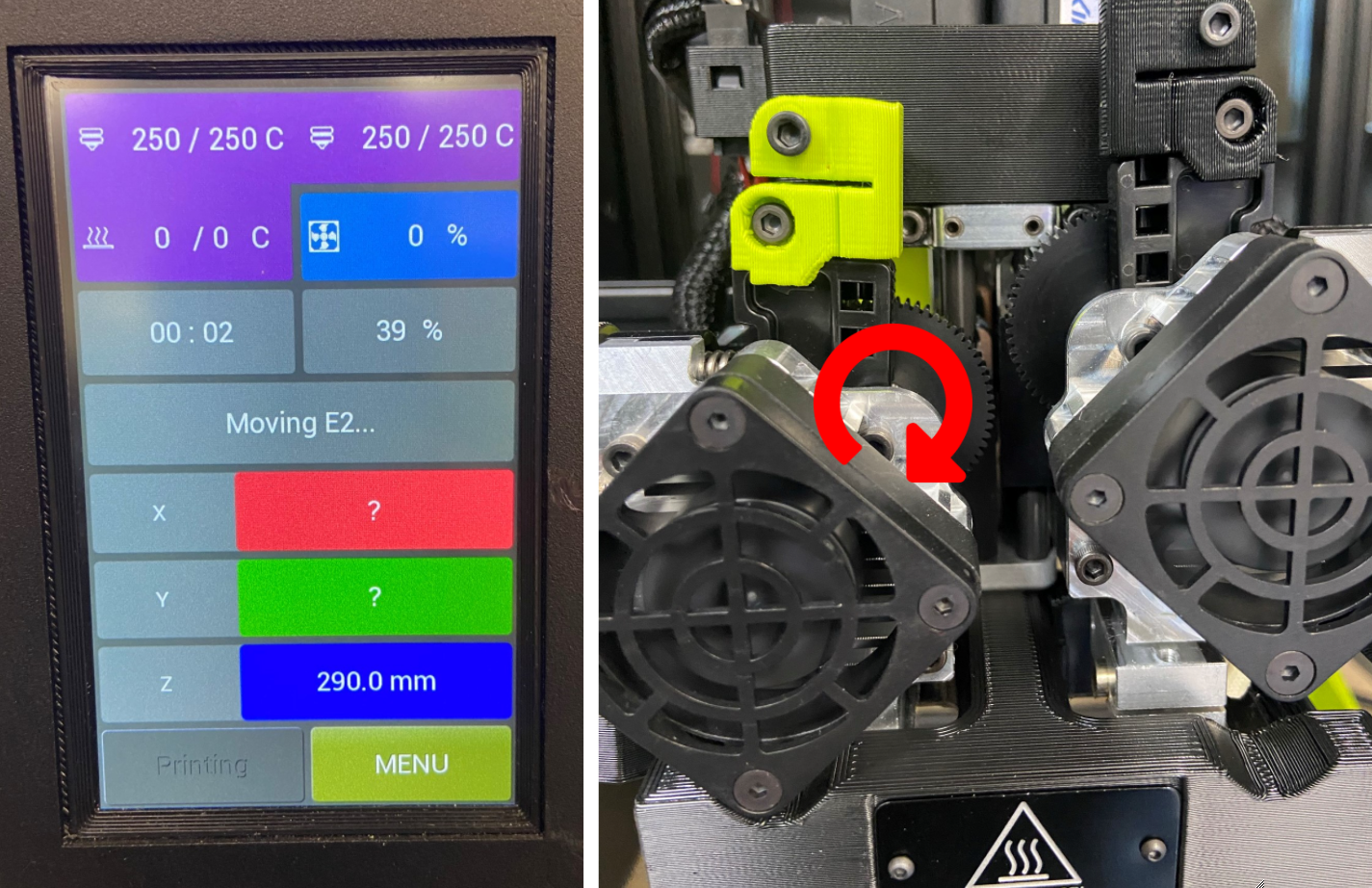
Both hot ends will heat to 250C and then the test stand will cycle both extruder motors in both directions.
Make sure the hot ends heat evenly with no long pauses or jumps and that the extruders are moving in the correct directions
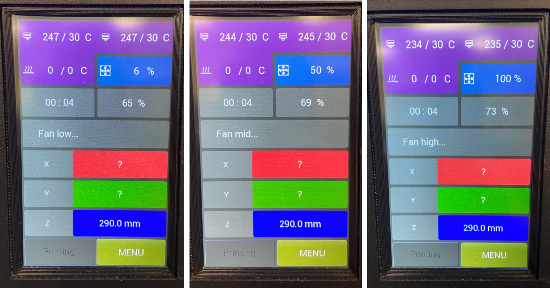
The test stand will now cycle the cooling fan, first at 6%, then at 50%, and lastly at 100%. Verify the fan spins at all three speeds.
The hot ends will then cool to 35C for handling before completing the test gcode, utilizing the cooling fan to slightly accelerate the cooling time.
MINTEMP, MAXTEMP, and HEATING FAILED are possible failure modes.


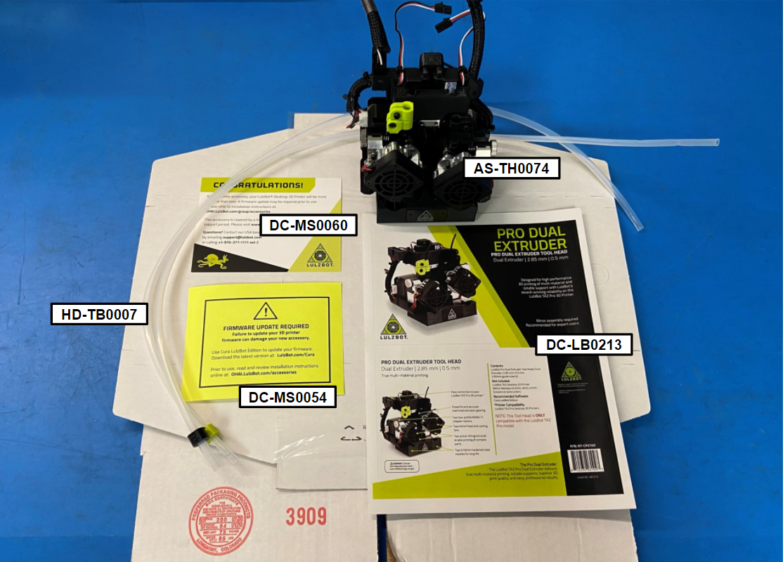
1x- [AS-TH0074] TAZ Pro Dual Extruder Tool Head
2x- [HD-TB0007] TAZ Pro, Feed Tube
1x- [DC-MS0054] Firmware Update Warning Cards
1x- [DC-MS0060] CONGRATULATIONS!- Accessory Instruction Card
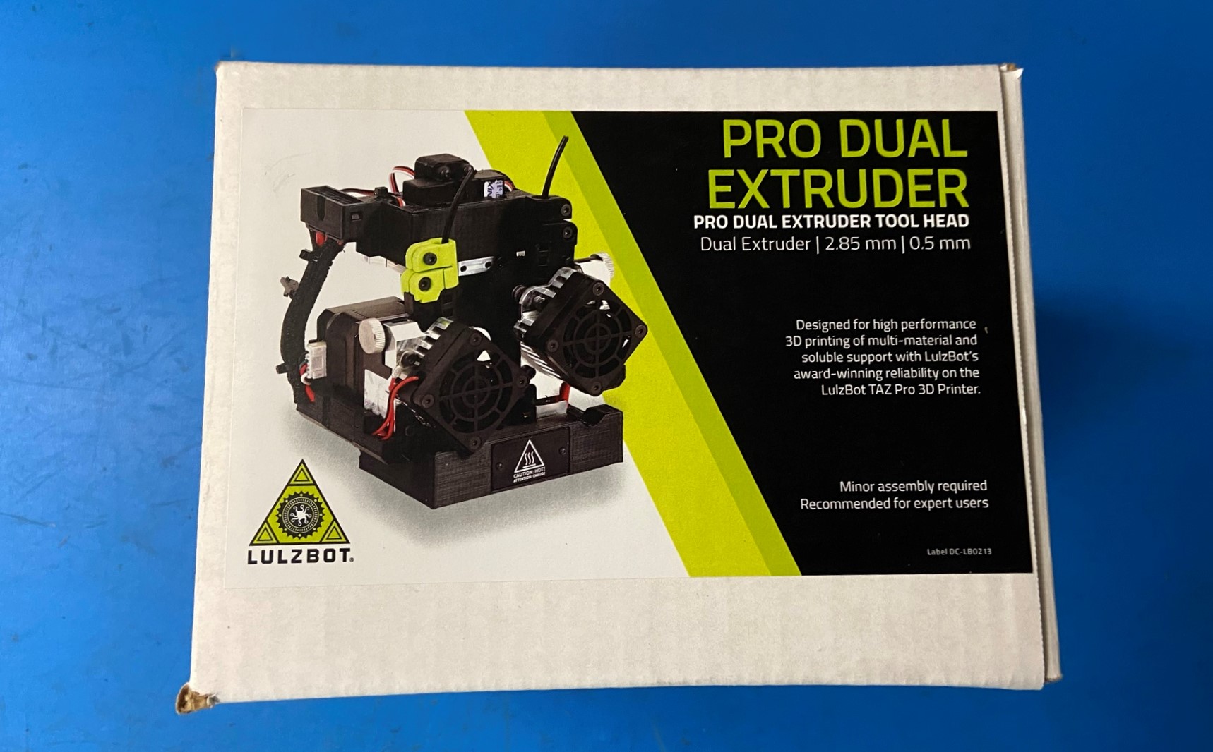
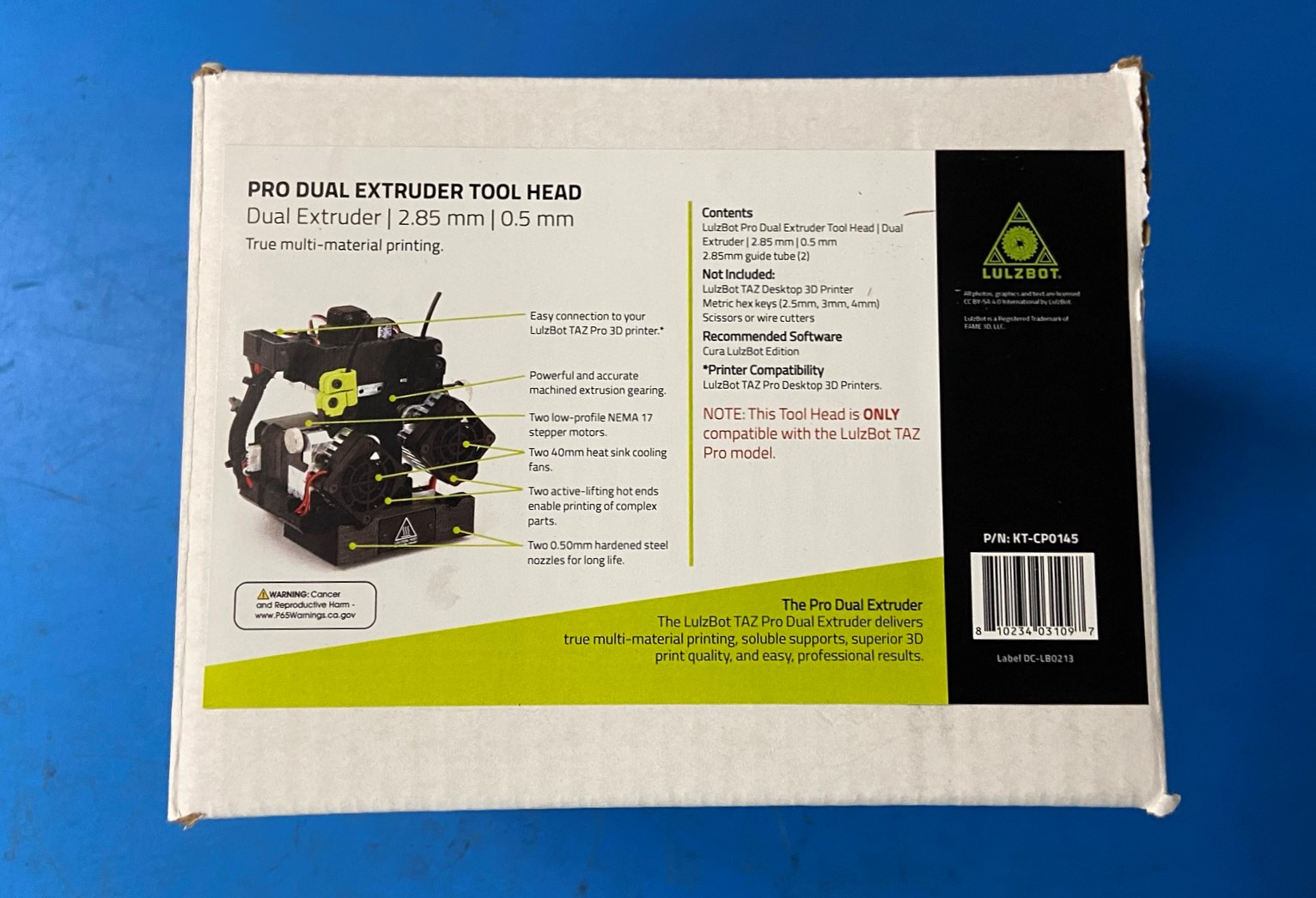
1x- [DC-LB0213] TAZ Pro, Front and Back Label
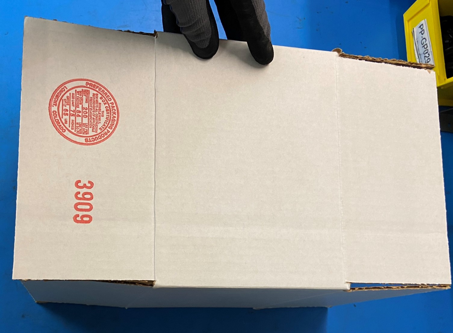
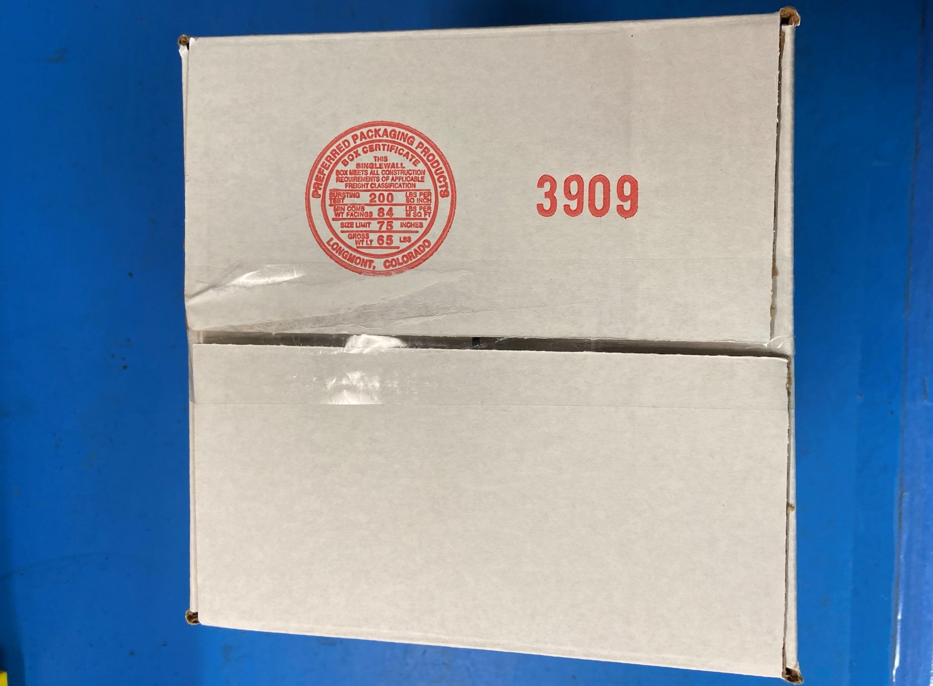
1x- [SH-PA0066] TAZ Pro, Tool Head Box 8" x 8" x 6"
1x- [SH-PA0065] TAZ Pro, Tool Head Korrvu Insert
1x- [SH-PG0131] #260 White Reinforced Gummed Tape with LulzBot Printed Logo
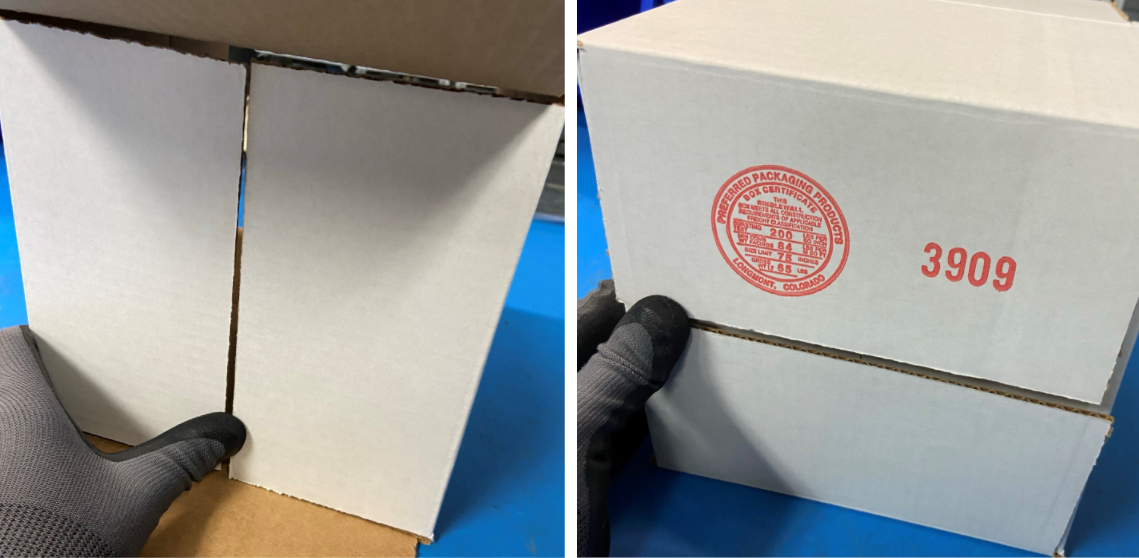
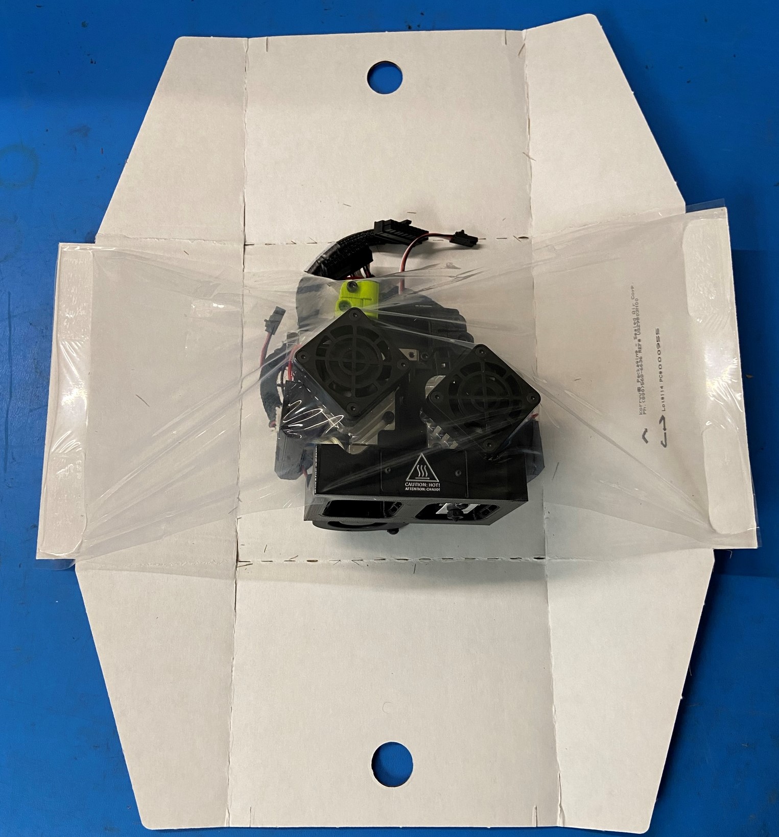
Take the flattened TAZ Pro, Tool Head Box 8" x 8" x 6" [SH-PA0066] and unfold it so it stands up, then take the two bottom tabs that are next to the tab with the red stamp and fold them in,
Next fold in the tab with the red stamp and the tab across from it.
Take a piece of packing tape and tape the bottom of the box
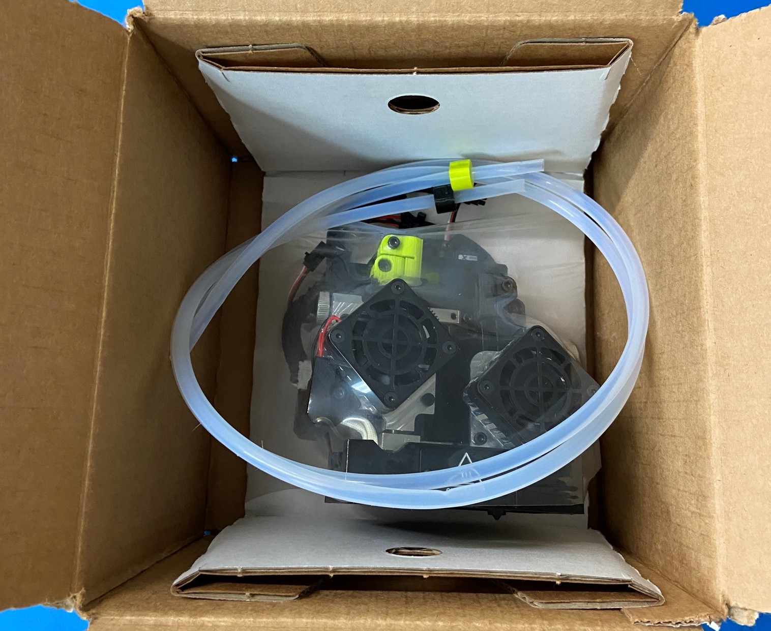
Fold the two sides without the finger holes up so that there is space for the tool head under the plastic wrap
Place the TAZ Pro Dual Extruder Tool Head [AS-TH0074] under the plastic wrap on the Korrvu [SH-PA0065]
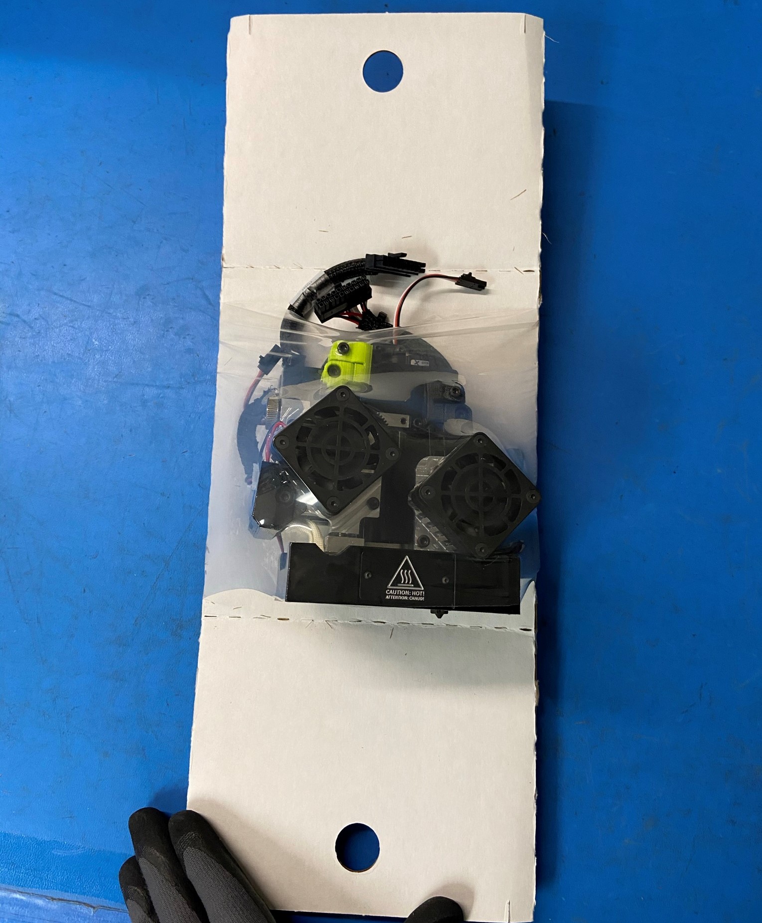
Fold the left side of the Korrvu back then fold the right side back then fold the top and bottom side up so it holds the left and right sides folded back so the plastic wrap is stretched around the tool head
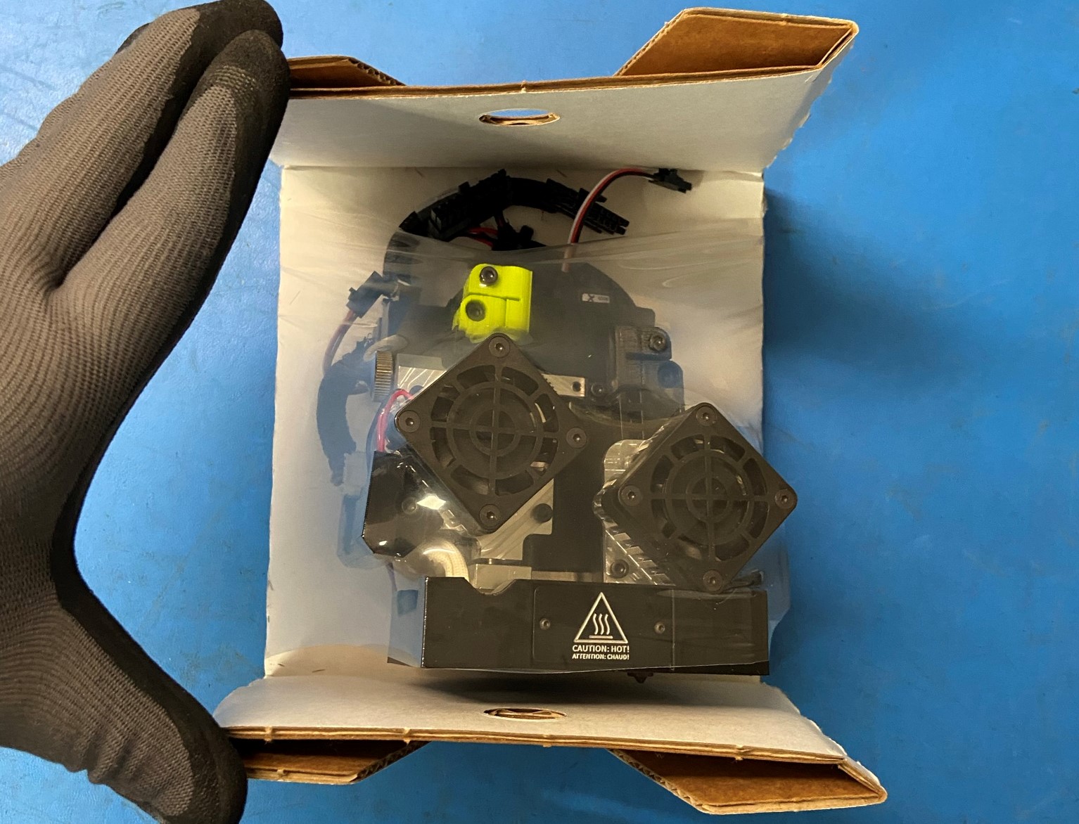
Then place the Korrvu and tool head inside the box

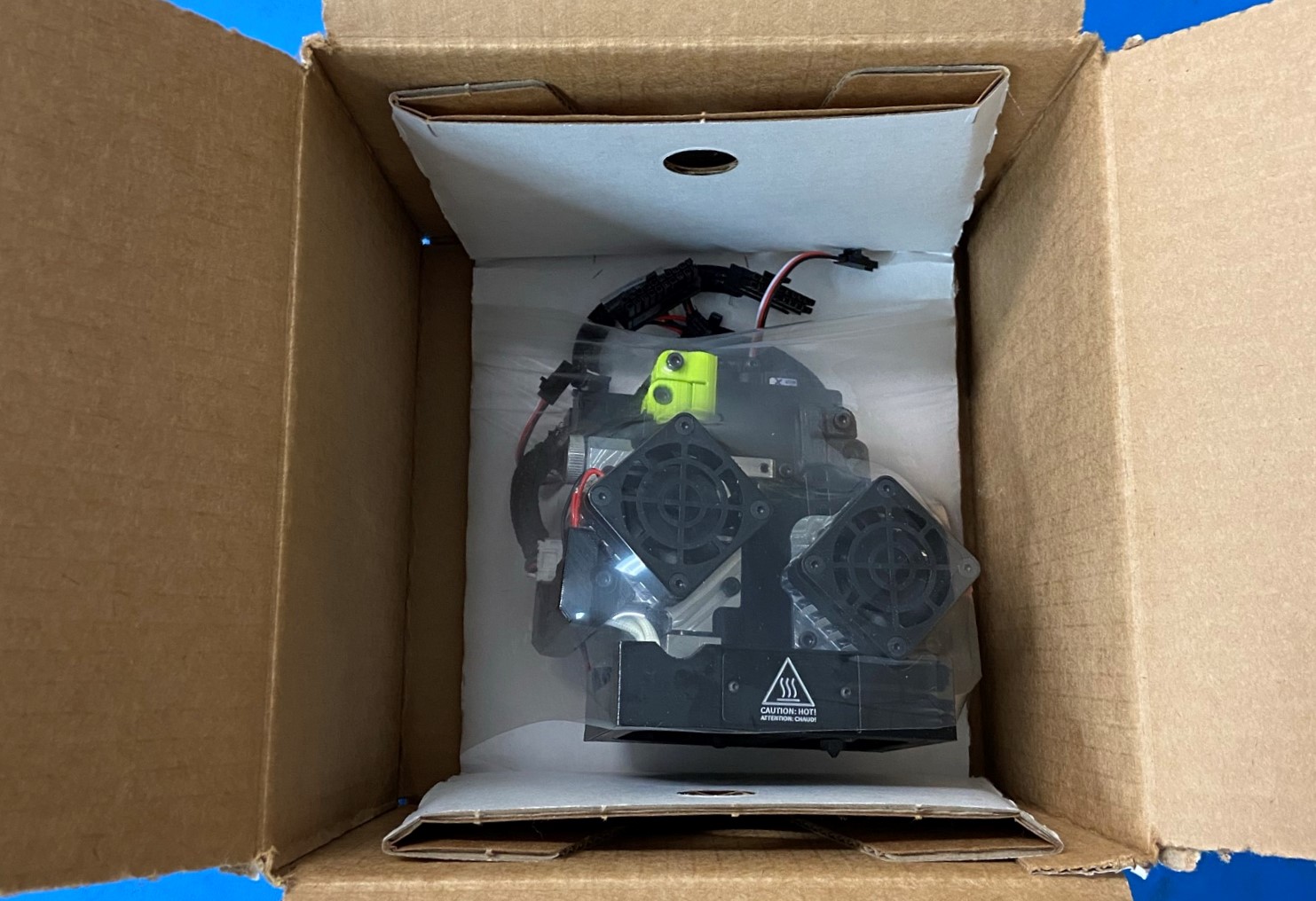
Place 2x Feed Tubes [HD-TB0007] inside the box onto of the tool head.
Note: wrap the two feed tubes into a circle
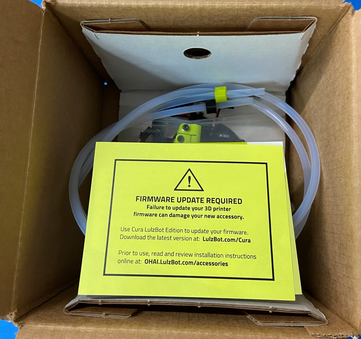
Next place the CONGRATULATIONS! Accessory Instruction Card [DC-MS0060] on top of the tool head and place the Firmware Update Warning Card [DC-MS0054] over the congratulations card

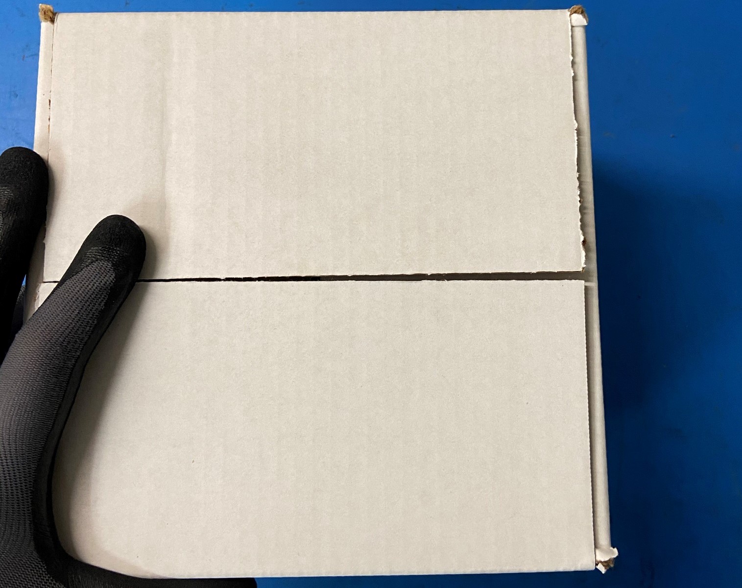
Now close the box and take it to the Uline tape machines.
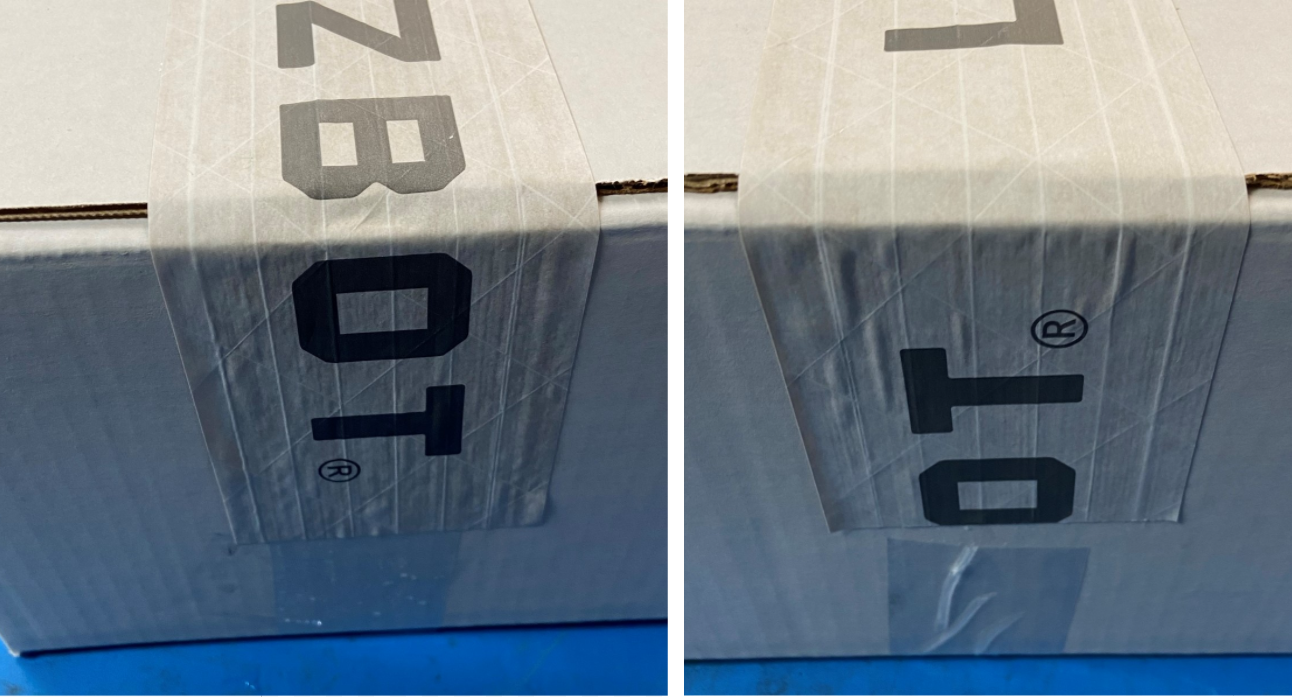
Use #260 White Reinforced Gummed Tape with LulzBot Printed Logo [SH-PG0131]
Select the short length on the machine.
Place the tape on one of the tabs about half way on, then fold the tab in so the tape secures both tabs together then make sure the tape runs down both sides of the box to secure the box from opening

Place the Front TAZ Pro Label [DC-LB0213] on the front of the box, then place the Back TAZ Pro Label [DC-LB0213] on the back of the box.
Note: The front label is on the top of the sheet and the back label is on the bottom