Open HardwareAssembly Instructions
Guides for installation and assembly of the LulzBot line of products made by FAME 3D LLC.
Guides for installation and assembly of the LulzBot line of products made by FAME 3D LLC.
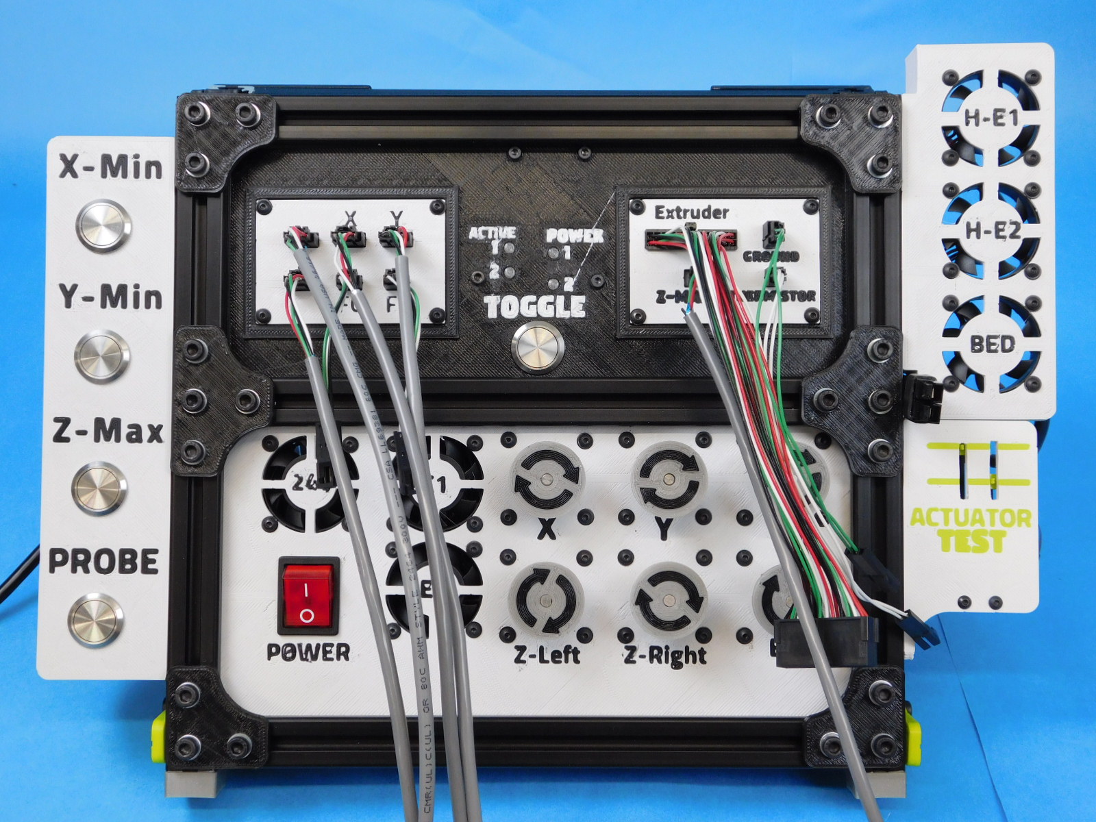
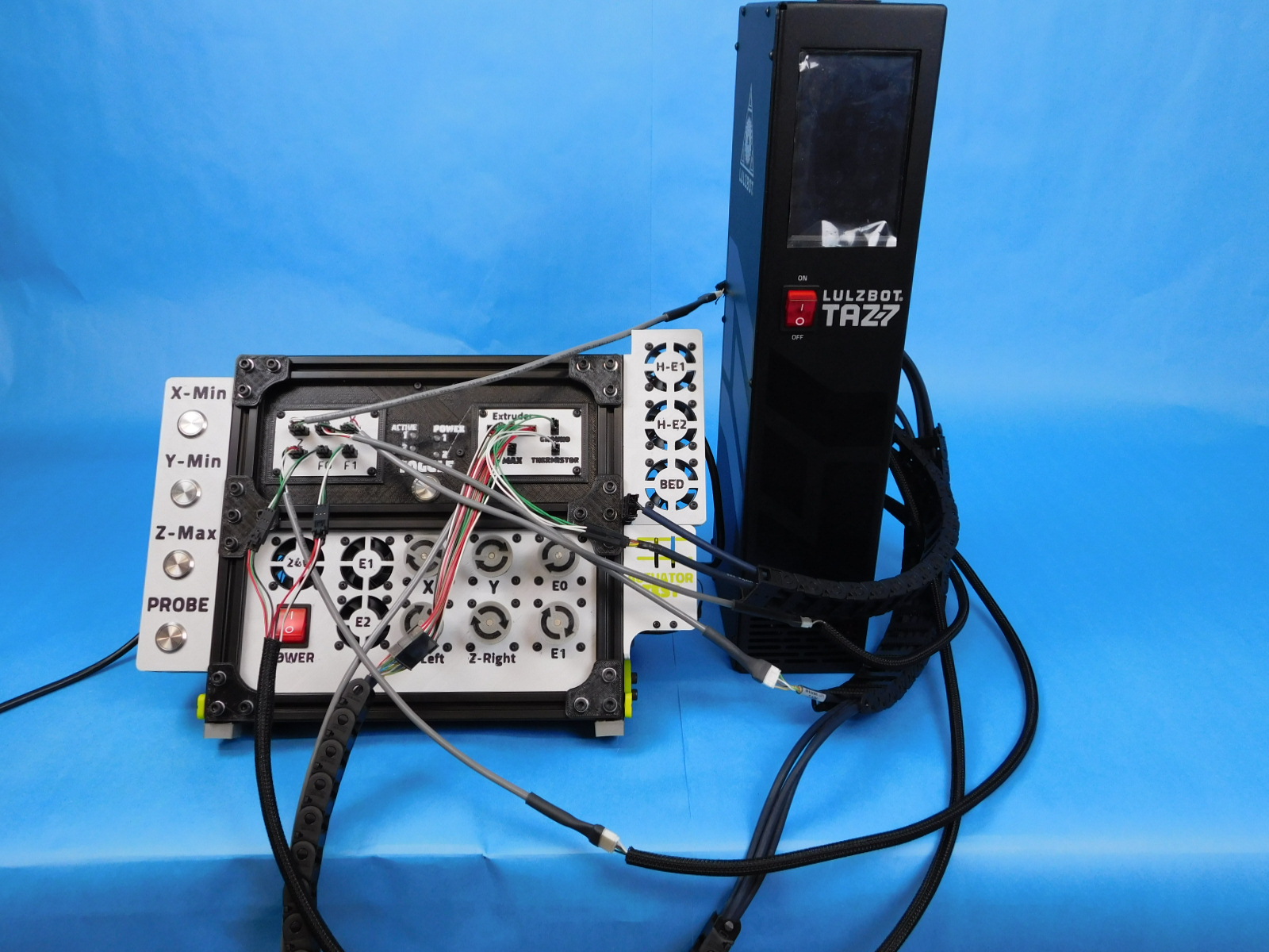
TAZ Pro Control Box Test Stand – test stand unit made to emulate external hardware of the LulzBot TAZ Pro. Requires its own power cable.
Workstation Computer with USB Cable – for flashing firmware to the Archim
NA Power Cable – will be used to power the box during testing
Preloaded USB drive – loaded with TAZ Pro Control Box test stand gcode. The user will run a gcode made specifically for this process.
GFCI Power Strip – the unit in testing and the CB Test Stand should both be powered with a GFCI power outlet, this is for safety.
Before testing can begin, firmware must be uploaded to the Control Box via the USB port on the rear of the chassis.
Connect a North American Power Cable to the receptacle located on the bottom rear of the chassis.
Connect the USB Cable from the Workstation Computer to the USB port on the rear of the chassis.
Power on the Control Box
Open CuraLE
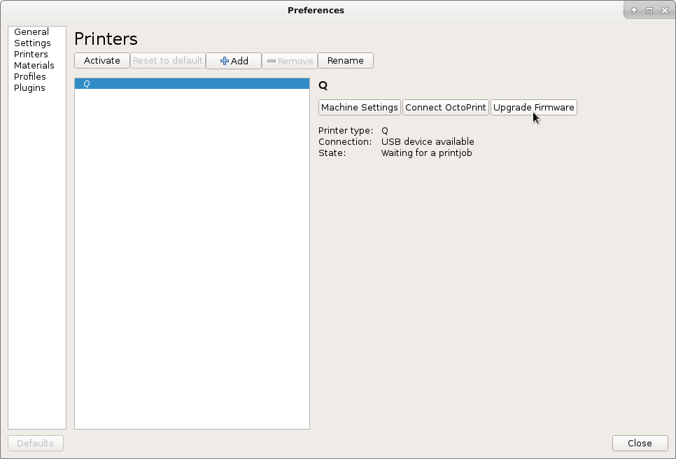
From the top menu bar select settings > printer > manage printers
Make sure "LULZBOT TAZ Pro Dual Extruder" is selected from the list of printers. Add it if needed.
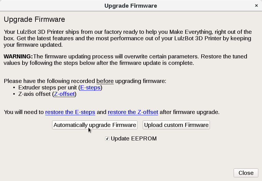
From the menu, select "Upgrade Firmware"
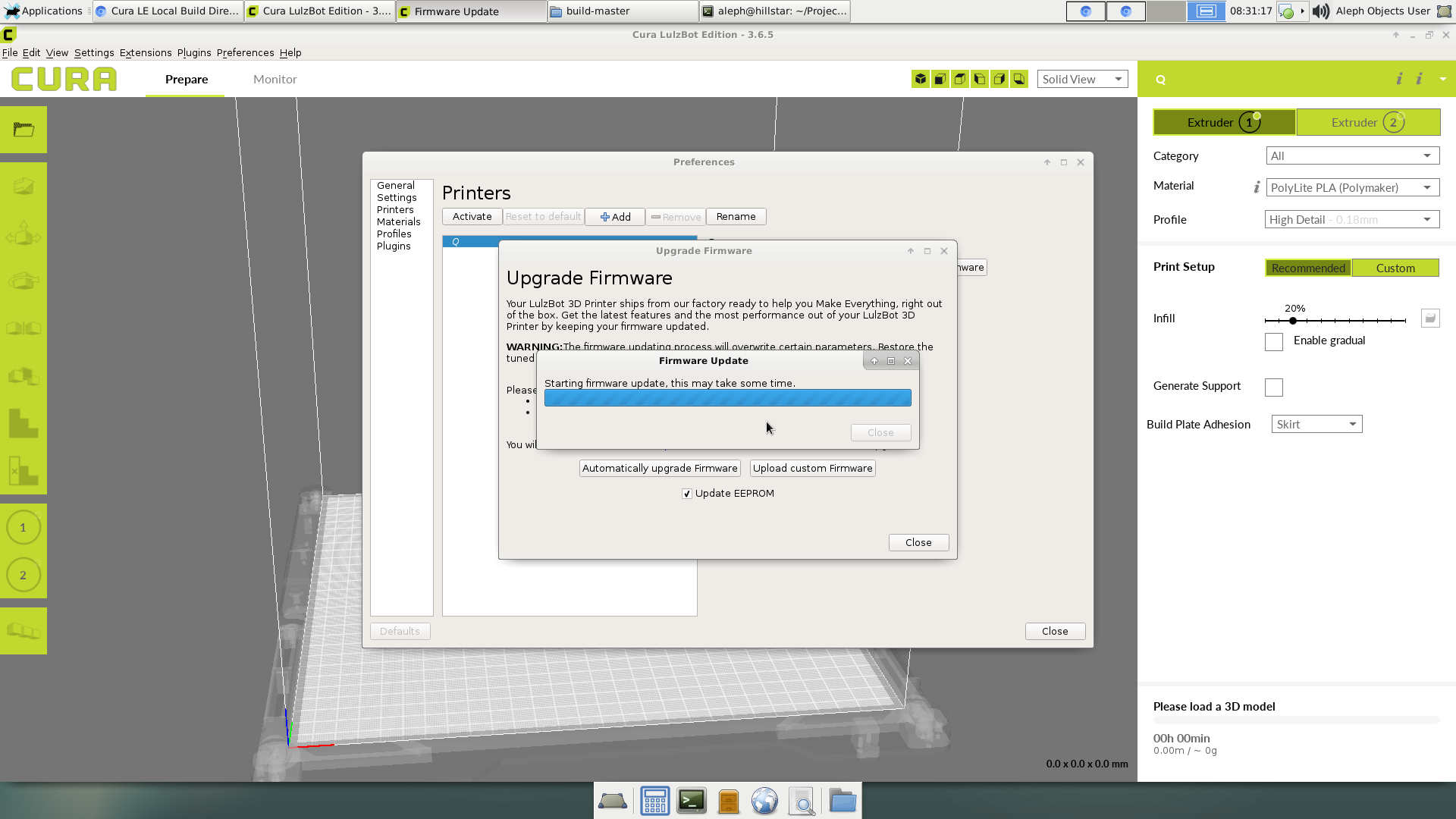
From the resulting dialogue, select "Automatically upgrade firmware".


Place the flashed unit to be tested to the right of the Control Box Test Stand
  | Extruder
  |
  | X motor
  |
  | Filament Sensor
  | Bed Thermistor
  | Bed Ground
  | Bed Power
  |
  | Z max
  | Z left motor
  | Y Motor
  | Z right motor
Connect all of the external connectors of the Control Box to the Control Box Test Stand:
Extruder Connector – 24 pin Molex Microfit connector
Z Motors – JST connectors; one short one long from bottom of interconnect
X Motor – JST connector; located mid-way on extruder harness
Y Motor – JST connector; middle length of 3 cables at bottom of interconnect
Filament Sensors – 3 pin Molex SL connectors; Green to F0, White to F1
Bed Power – Anderson connector
Bed Ground – 3 pin Molex SL connector
Bed Thermistor – 2 pin Molex SL connector
Z Max – 2 pin Molex SL connector located at interconnect housing
Begin by powering on the connected unit to be tested and the Control Box Test Stand
The following checks must be performed BEFORE starting the test gcode:
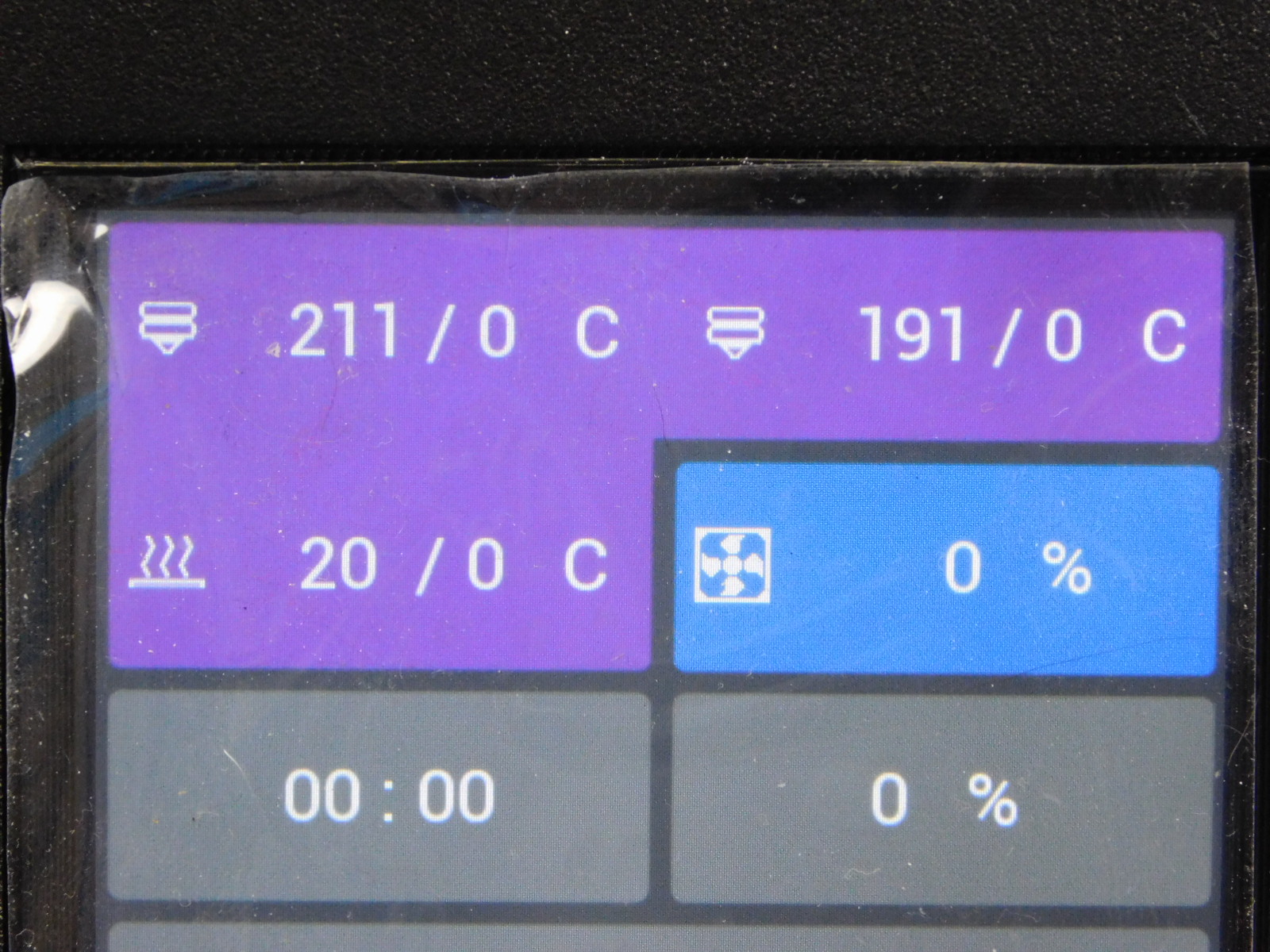
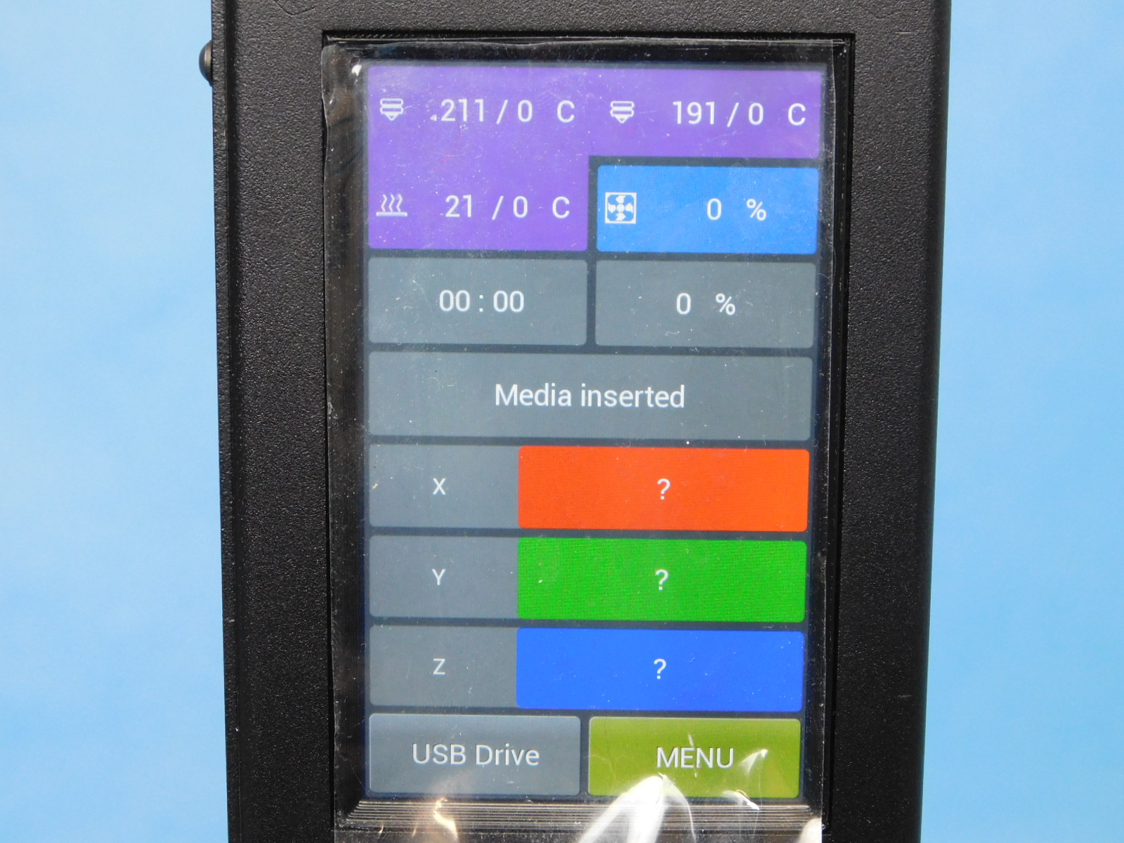
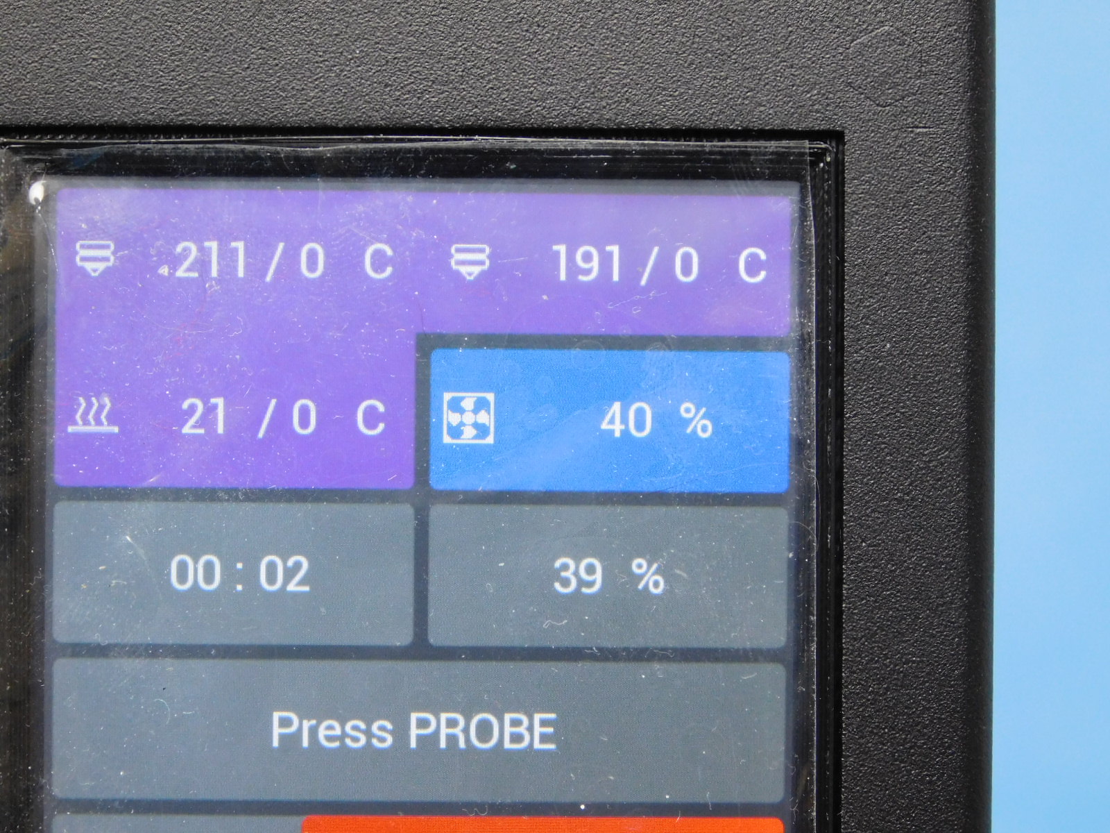
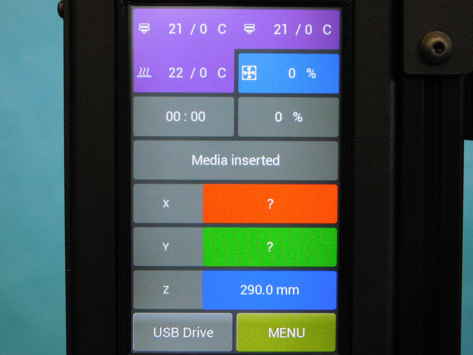
1. Check thermistor values:
Hot End 1 should read 211C
Hot End 2 should read 191C
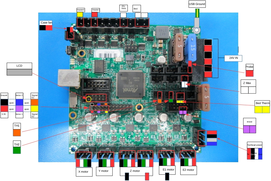
If the values listed above are reversed or no value is shown (0) the unit has failed testing and must be reworked. In this case, the two thermistor connectors inside the unit are connected incorrectly. Return the unit to an ESD safe work area, remove the Electronics Cover, and verify correct connector locations. See (link to pin out diagram)
2. Check bed thermistor value:
Should read close to room temperature in degrees C, if no value is shown, verify external connection before returning the unit to an ESD safe work area for rework.
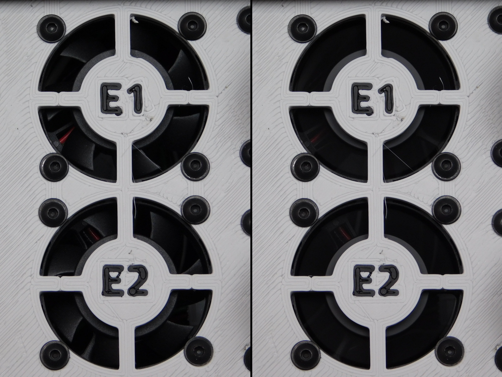
3. Check E1/E2 Fans:
Both heat sink fans (labeled E1/E2 and located on bottom panel of CB Test Stand) should be spinning any time the unit is powered on. If either of these fans is not functioning the unit has failed the test and must be reworked. After returning the unit to an ESD Safe work area and removing the cover, verify the tool head power connector is pinned correctly and properly connected. See Pinout Diagram
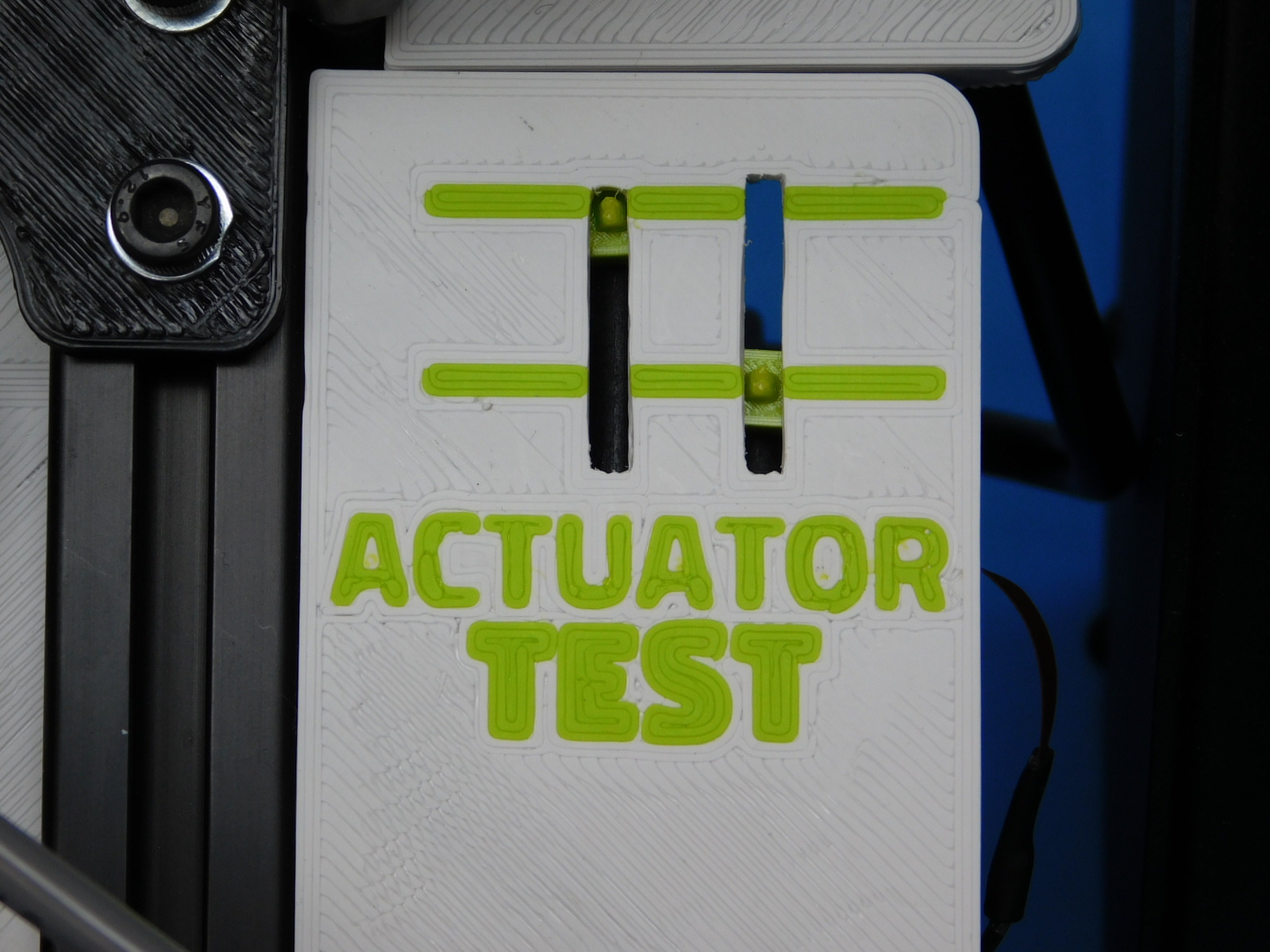
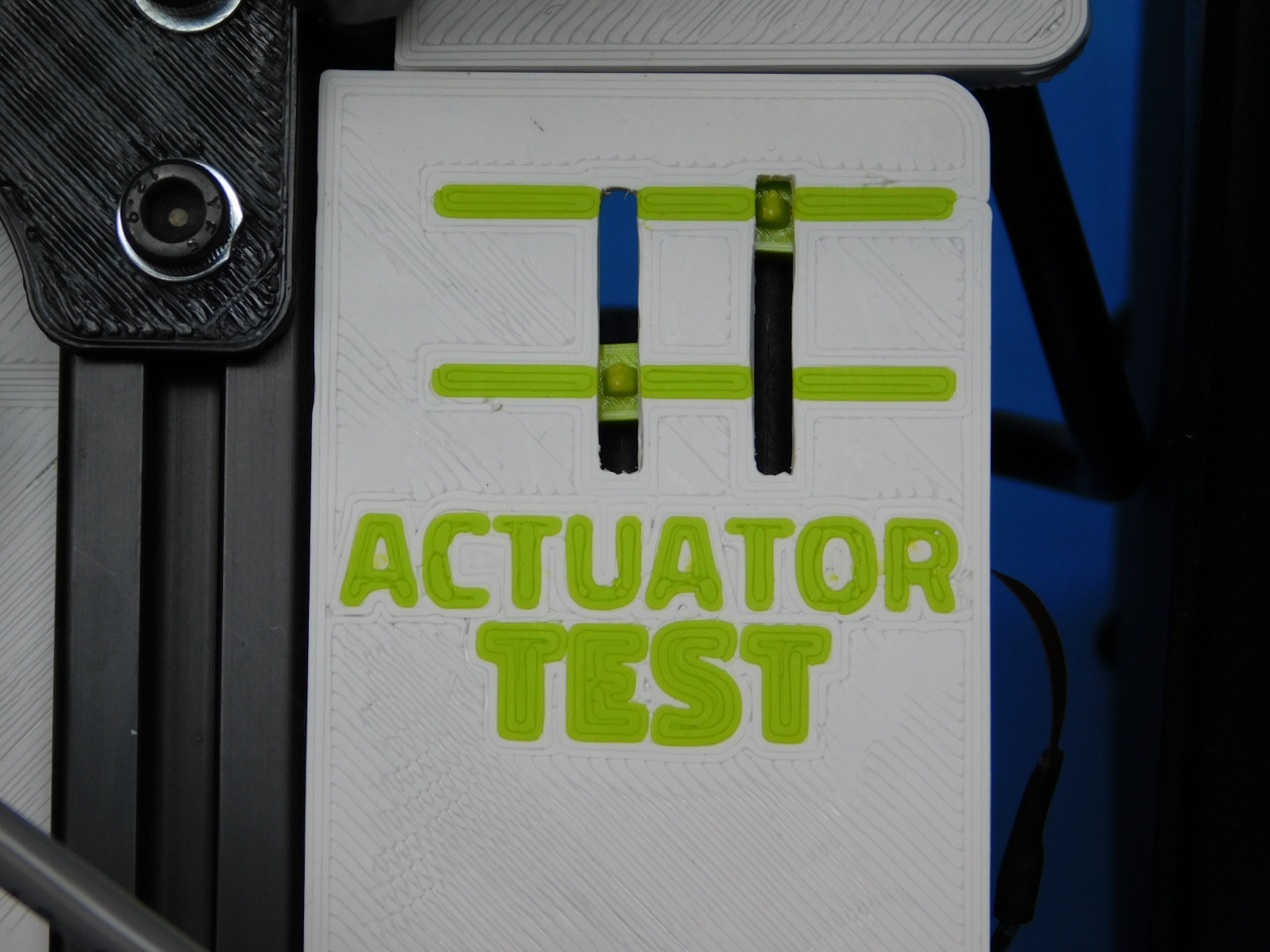
4. Actuator function:
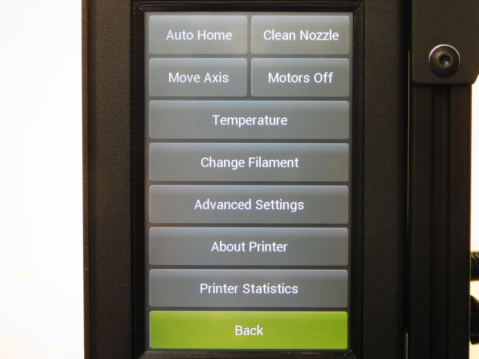
The actuator test located on bottom right of the test stand is used for visualizing proper function of the actuator circuits. Both indicator should rest within the green zones in either position. To cycle between positions, select MENU > Change Filament and use the 1 & 2 buttons at the top of the display. The left actuator should be at the top when number 1 is selected. When number 2 is selected, the left actuator should lower and the right raise to the top.
If an actuator fails to move, return the unit to an ESD Safe work area for diagnosis.
5. LCD Screen:
Verify that the touch screen is installed straight in relation to the chassis, use straight horizontal lines of the GUI to reference against sheet metal. Does it look straight? If it is determined to be crooked, return the unit to an ESD Safe work area for rework.
6. Case Fan:
Verify that the case fan is blowing air OUT from the rear of the case. A sticky note or other small piece of paper may be used to verify direction of flow.
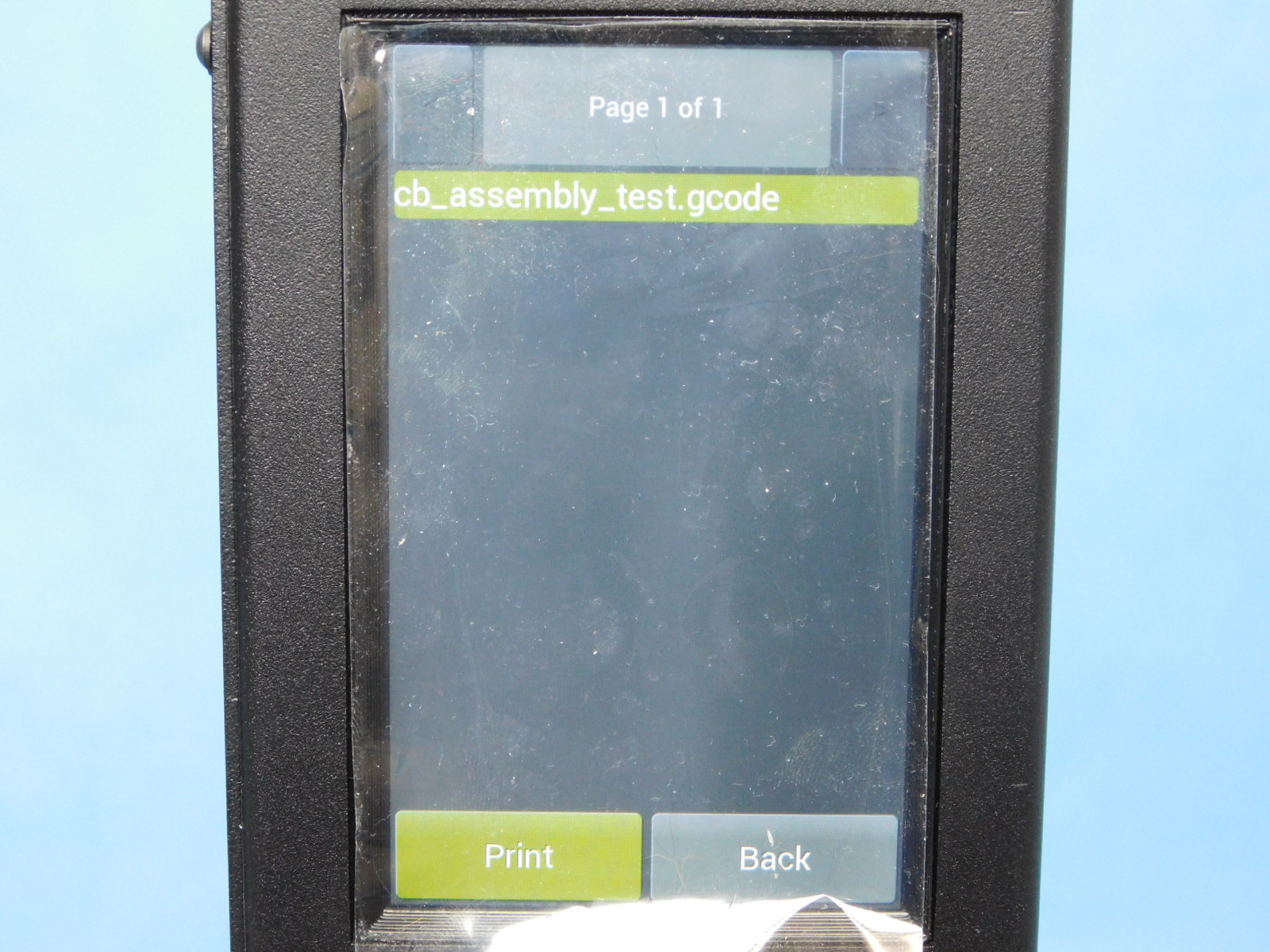
If the unit passed the above checks, plug in the preloaded USB drive to the port on the top of the unit.
Before proceeding, familiarize yourself with steps 6 thru 8 as the test moves quickly at the start and a delay on the user’s part will require a restart of the test from this step
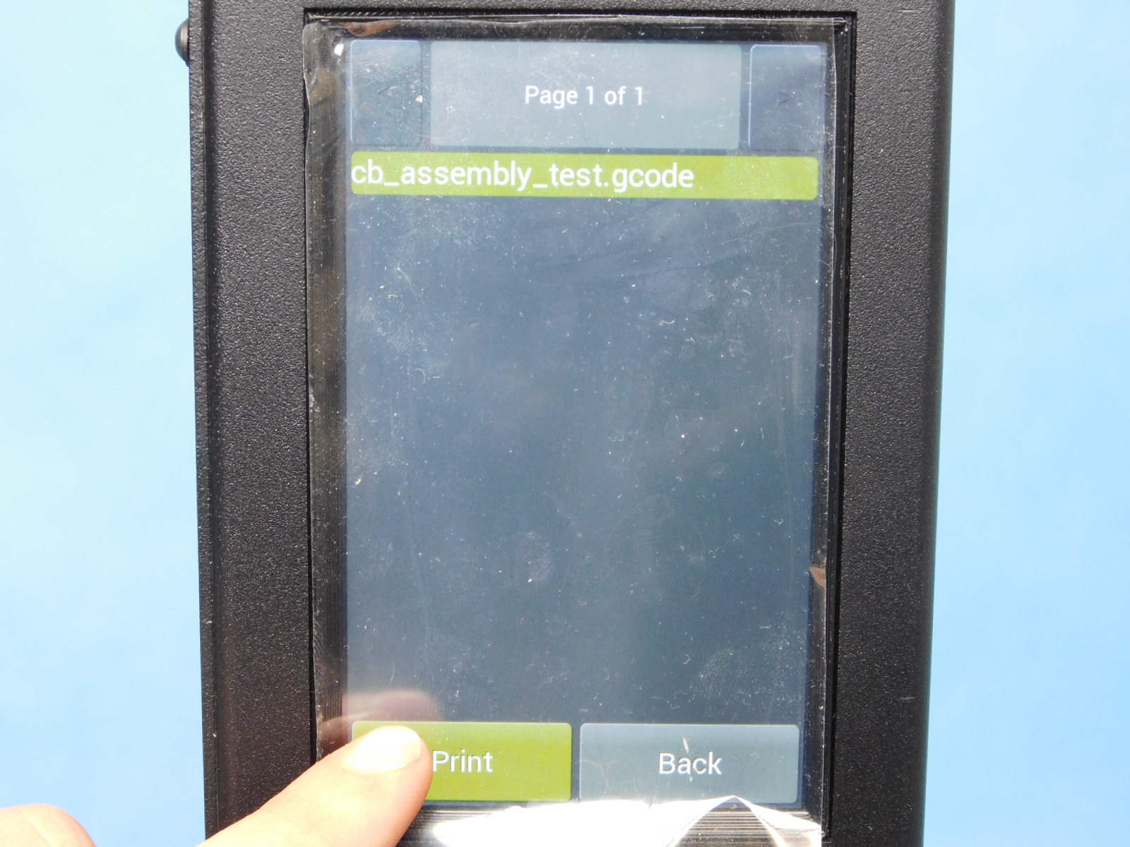
Press the button bottom left of the screen labeled “USB Drive,” select the CB_Assembly_Test.gcode and then select “Print”
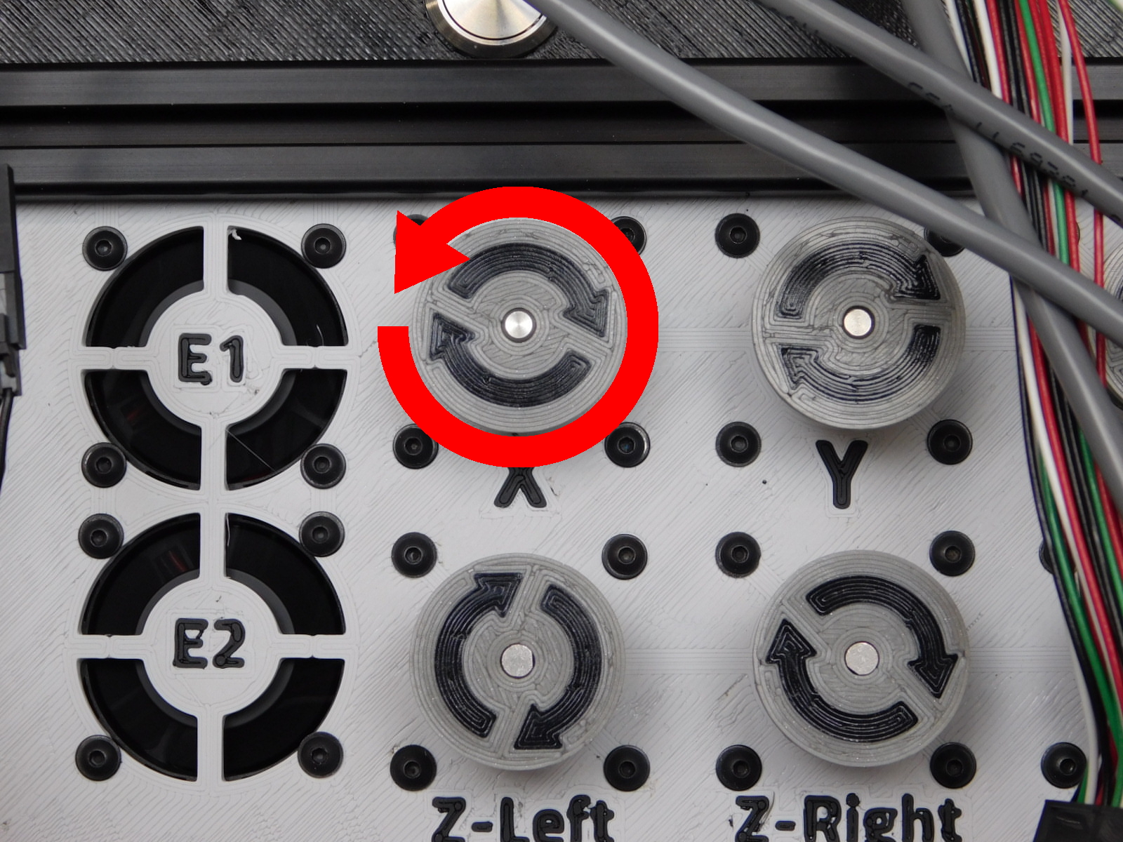
After selecting “Print” the unit will chime and begin the test gcode by homing the X axis, the motor should begin by spinning counter-clockwise.
Press and release the X-Min button on the left of the CB Test Stand within 10 seconds or the unit will report “Homing Failed” and the test must be restarted from step 5.
This emulates the X bump stop on the printer.
The X Motor should now slowly turn clockwise and then turn very fast clockwise.
Failure conditions:
If the X Motor moves clockwise first, the motor is wired incorrectly.
If the motor fails to move at all, check external connections first.
If the X Motor jiggles or twitches, this is indicative of poor connection on one of the individual wires of the motor lead.
In the event that the above failures occur and are not rectified by checking connections, return the unit to an ESD Safe work space for diagnosis and repair.

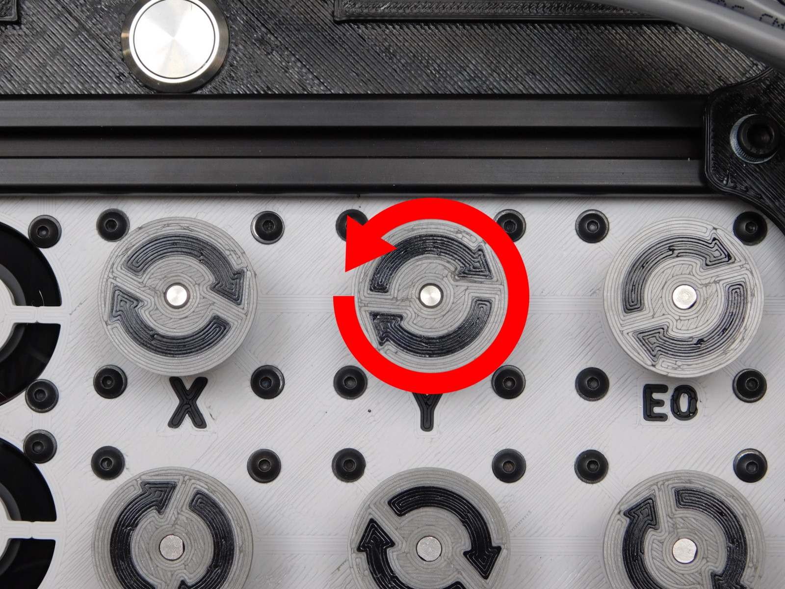
The Y Motor will begin moving counter-clockwise immediately following the X Motor’s rapid clockwise move.
Press and release the Y-Min button on the left side of the CB Test Stand within 10 seconds or the unit will report “Homing Failed” and the test must be restarted from step 5.
This emulates the Y bump stop on the printer.
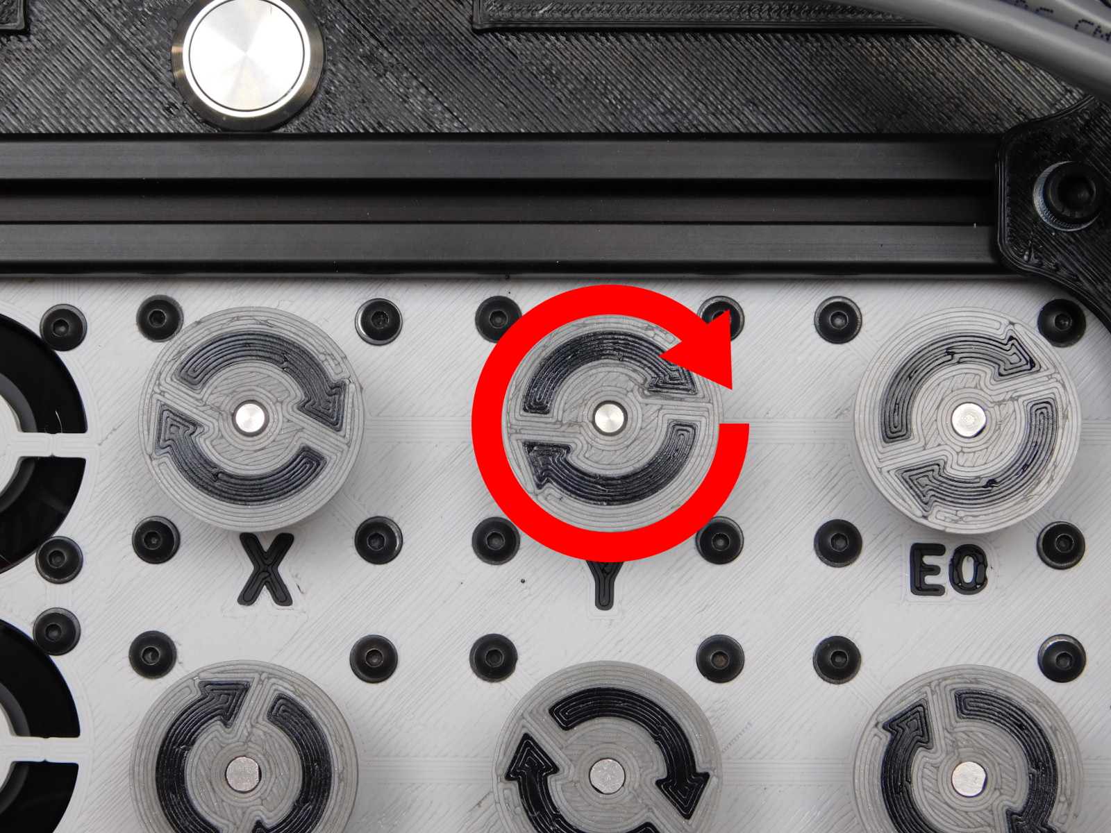
The Y Motor should now spin clockwise rapidly.
Failure conditions:
If the Y Motor moves clockwise first, the motor is wired incorrectly.
If the motor fails to move at all, check external connections first.
If the Y Motor jiggles or twitches, this is indicative of poor connection on one of the individual wires of the motor lead.
In the event that the above failures occur and are not rectified by checking connections, return the unit to an ESD Safe workspace for diagnosis and repair.
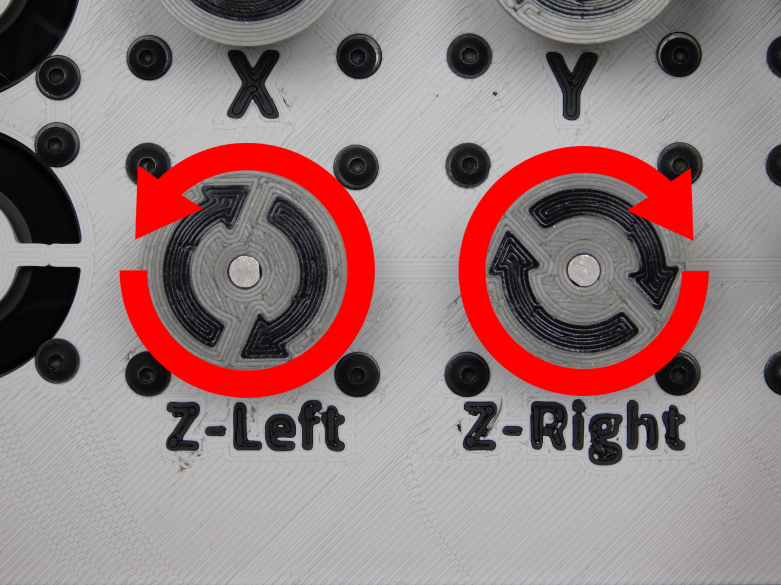
The Z Motors will now begin moving simultaneously, the left one turning clockwise and the right turning counter-clockwise.
Press and release the Z-Max button TWICE on the left side of the CB Test Stand within 10 seconds and one immediately after the other or the unit will report “Homing Failed” and the test must be restarted from step 5.
This emulates the Z Max switch on the printer.
The motors should now spin rapidly the opposite direction.
Failure conditions:
If the Z Left Motor moves counter-clockwise first, the motor is wired incorrectly.
If the Z Right motor moves clockwise first, the motor is wired incorrectly.
If the motor fails to move at all, check external connections first.
If the Y Motor jiggles or twitches, this is indicative of poor connection on one of the individual wires of the motor lead.
In the event that the above failures occur and are not rectified by checking connections, return the unit to an ESD Safe work space for diagnosis and repair.

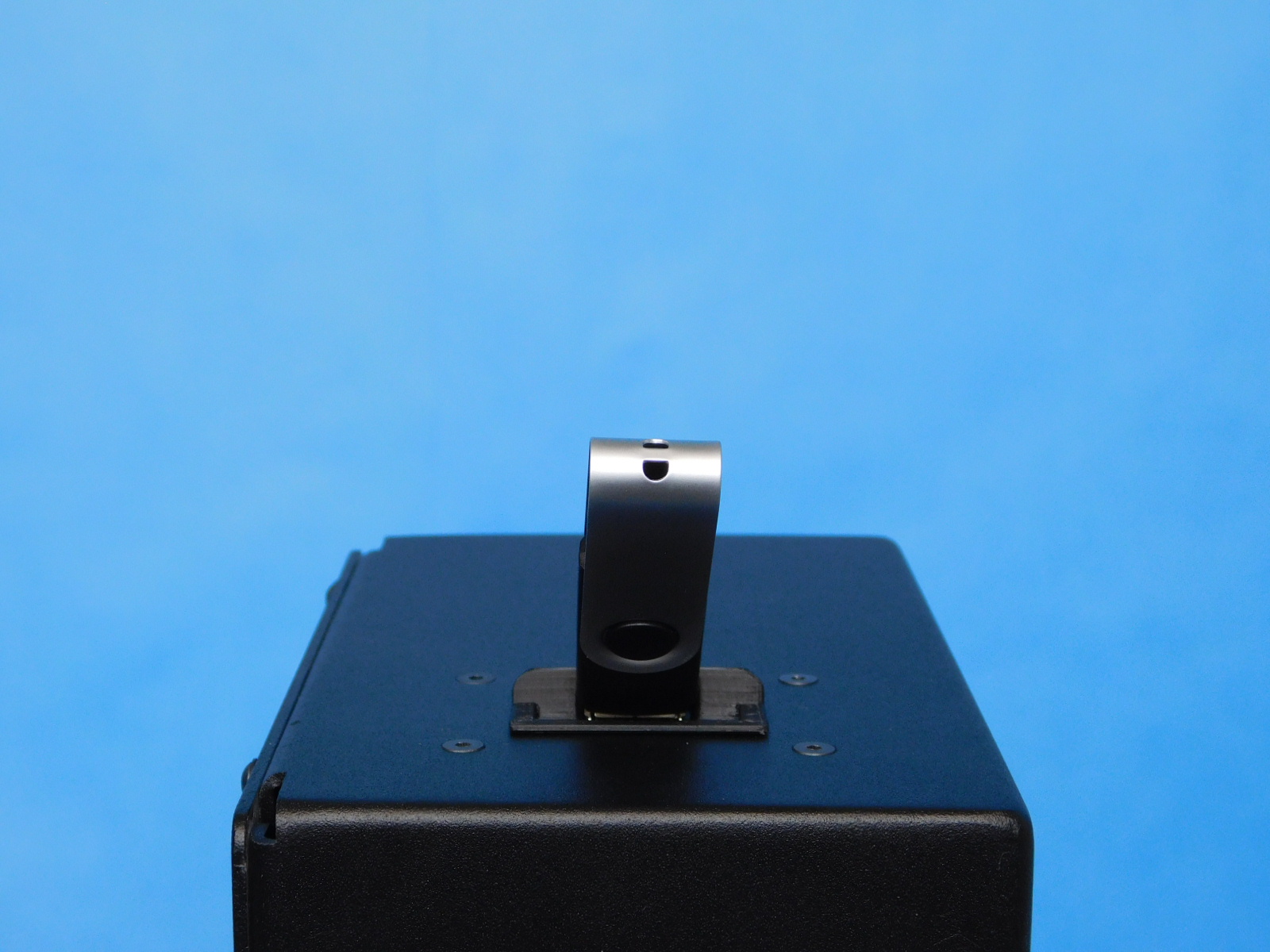
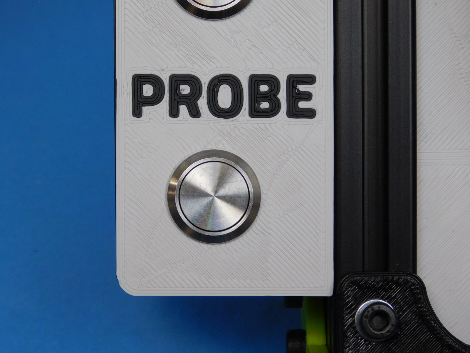
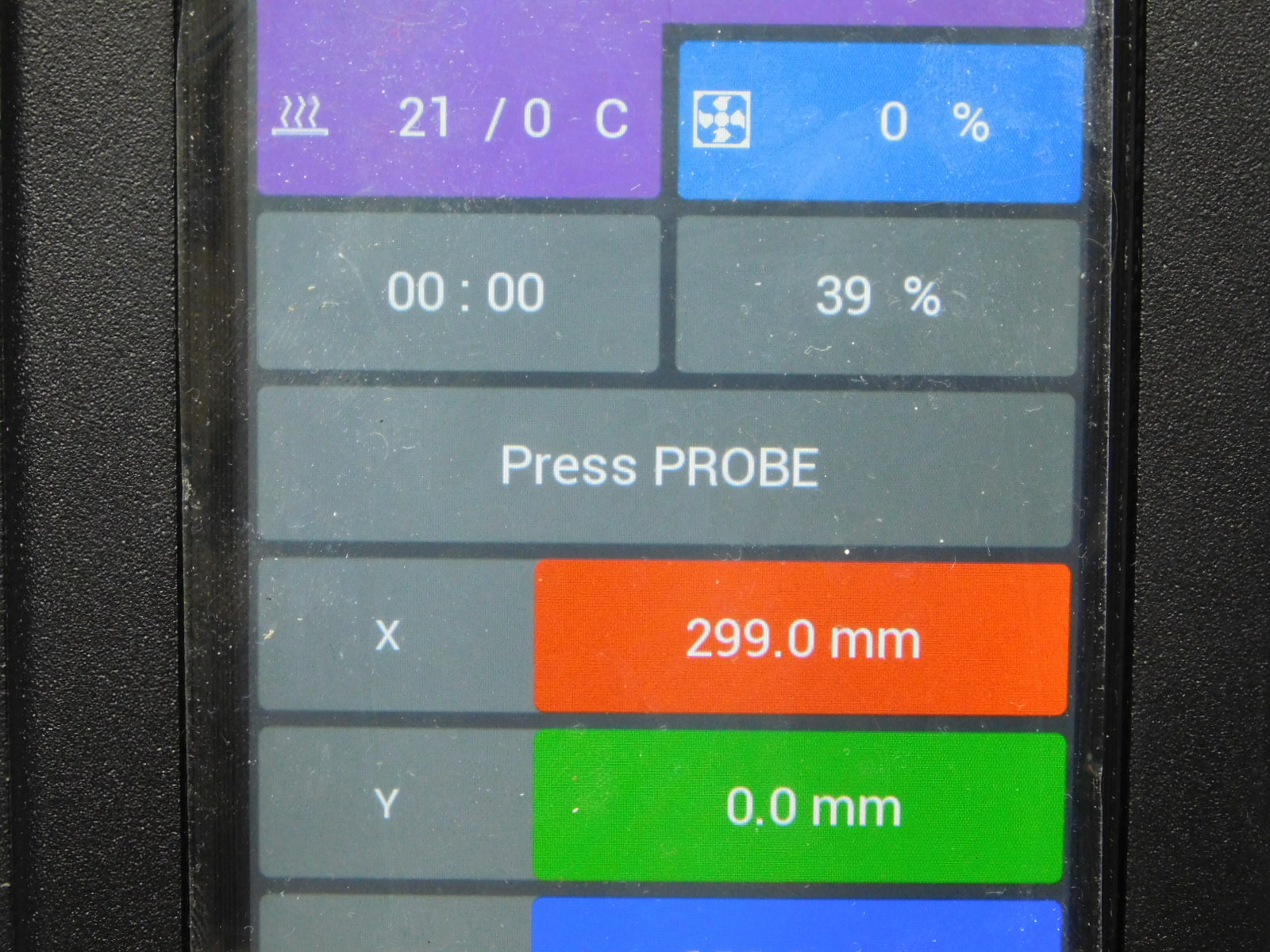
The unit will now wait indefinitely for the user to press the Probe button on the left side of the CB Test Stand.
Now is a good time to read ahead if you haven’t already, so that you’re aware of the conditions that must be visually verified from this point forward.
Press and release the Probe button.
Failure condition:
If the unit does not proceed with the test following actuation of the probe button, there is not continuity in the circuit and the unit has failed the test.
Check external connections to the CB Test Stand and reattempt before returning the unit to an ESD Safe workspace for diagnosis and rework.
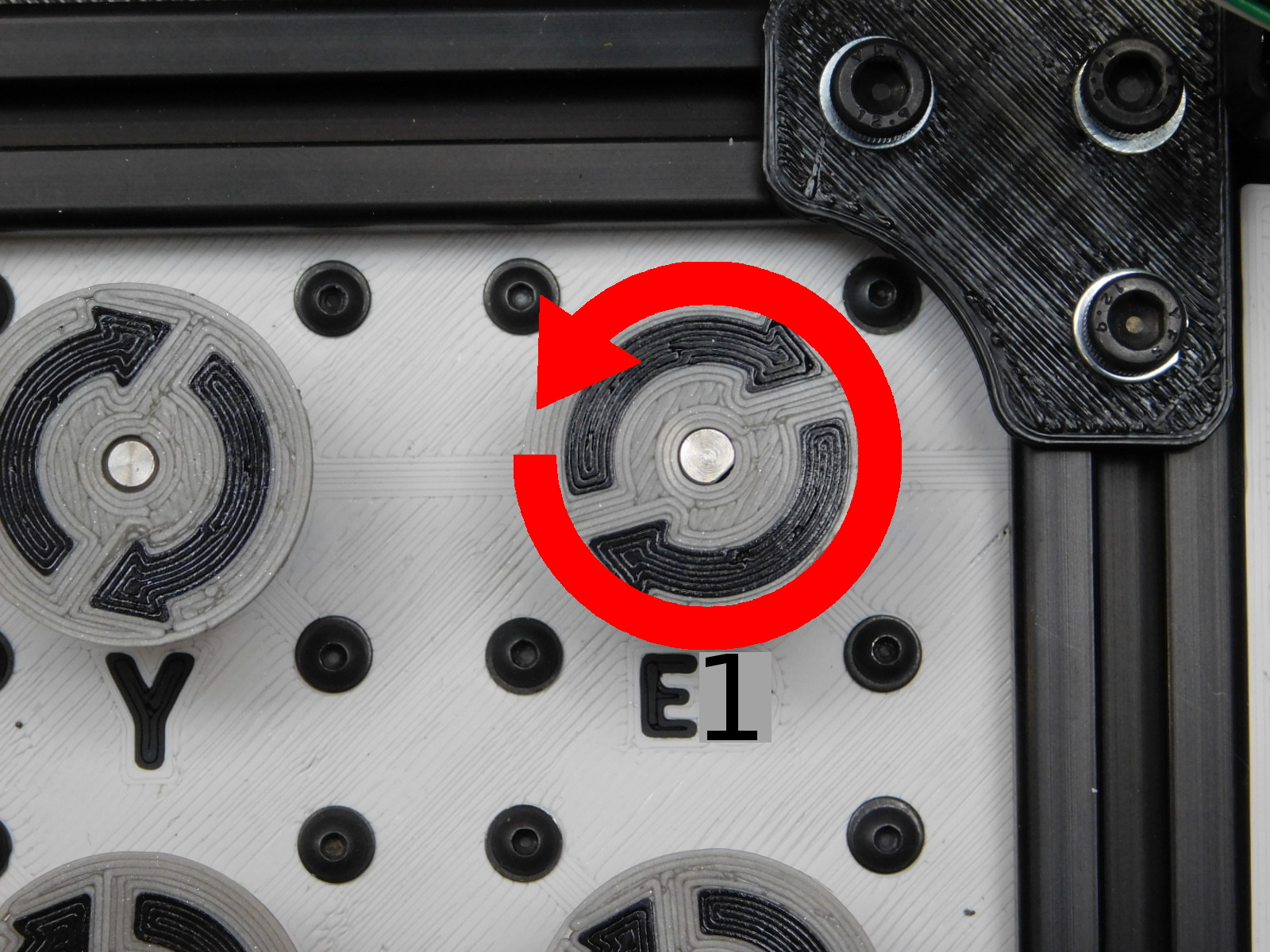
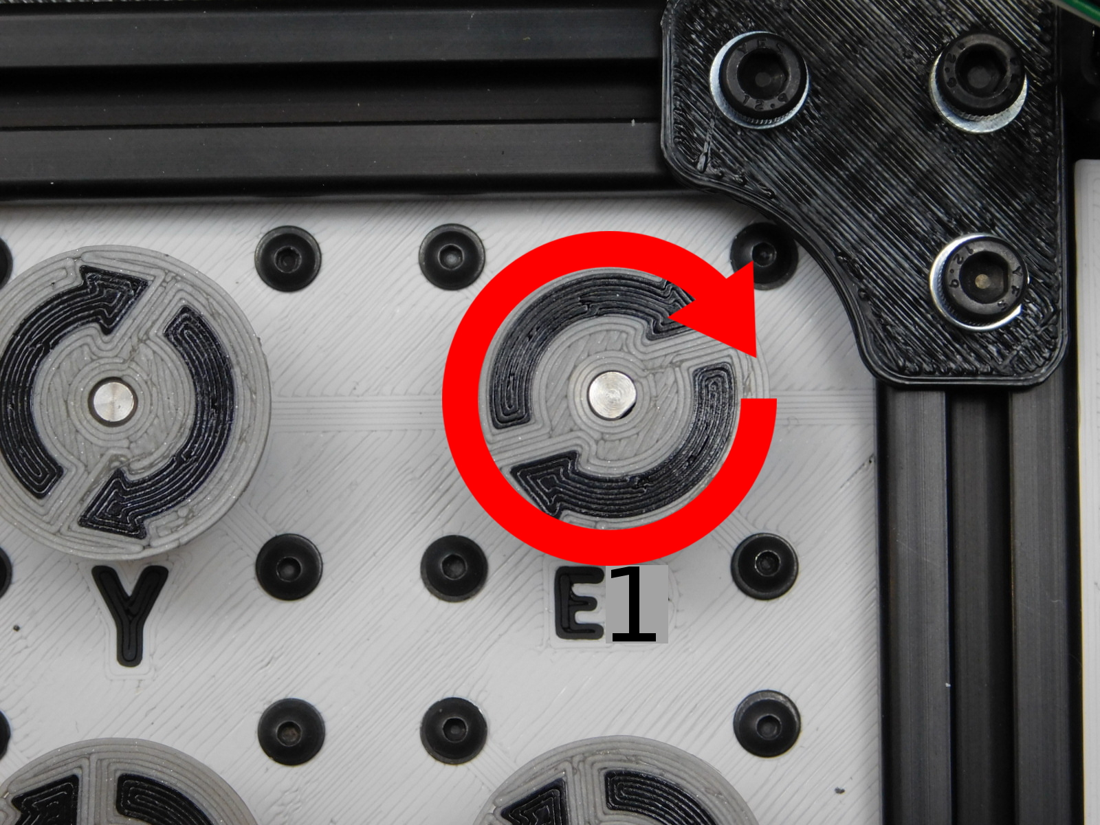
Immediately following actuation of the probe button, the E1 Motor on the test stand should begin moving counter-clockwise.
If the motor moved clockwise first or failed to move it is not wired correctly and the unit has failed the test.
To confirm the motor moved counter-clockwise and proceed with the test, press the PROBE button.
The motor will now spin clockwise.
To confirm and proceed with the test press the PROBE button.
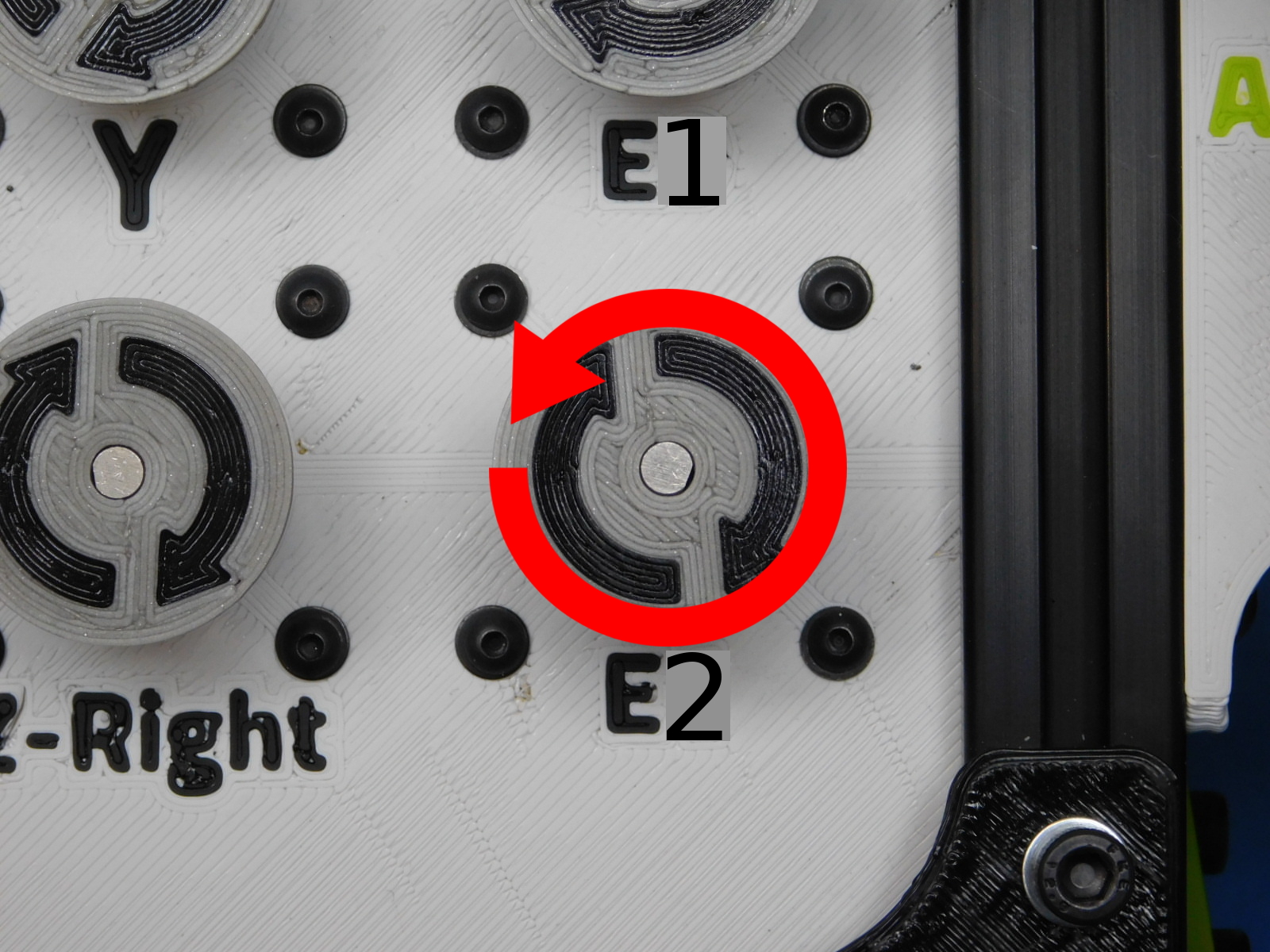
The E2 motor will now move counter-clockwise.
If the motor moved clockwise first or failed to move it is not wired correctly and the unit has failed the test.
To confirm the motor moved counter-clockwise and proceed with the test, press the PROBE button.
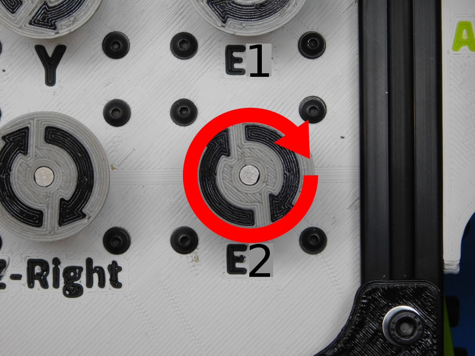
The motor will now spin clockwise.
To confirm and proceed with the test press the PROBE button.
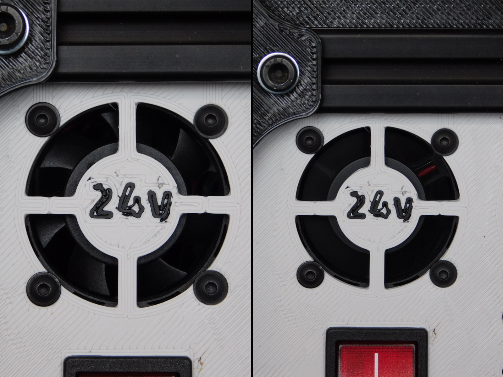
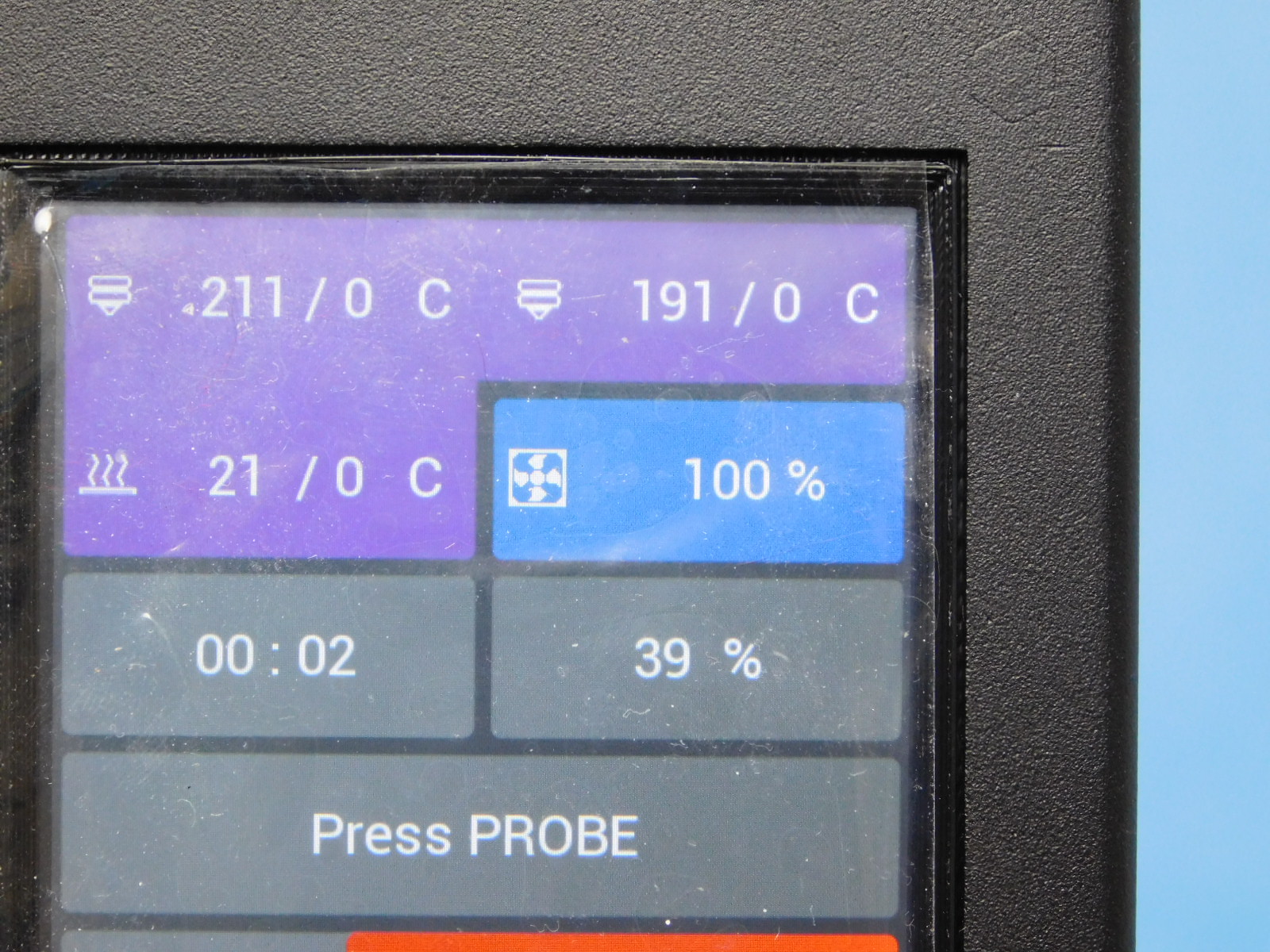
The 24v fan on the CB Test Stand should now be spinning at 40%, it will then speed up to 100%
If the fan doesn’t turn on, the unit has failed the test. Check external connections to the CB Test Stand before returning the unit to an ESD Safe work area for diagnosis and rework.
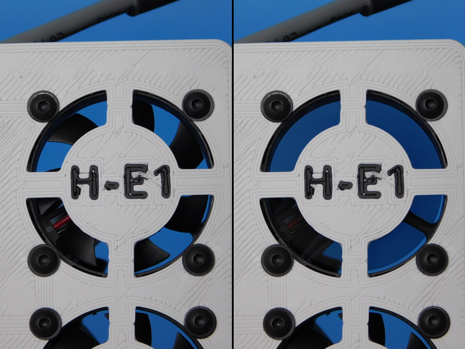
The fan on the right panel of the CB Test Stand labeled ”H-E1” should now turn on.
If the fan did not turn on the unit has failed the test and should be returned to an ESD Safe workspace for diagnosis and repair.
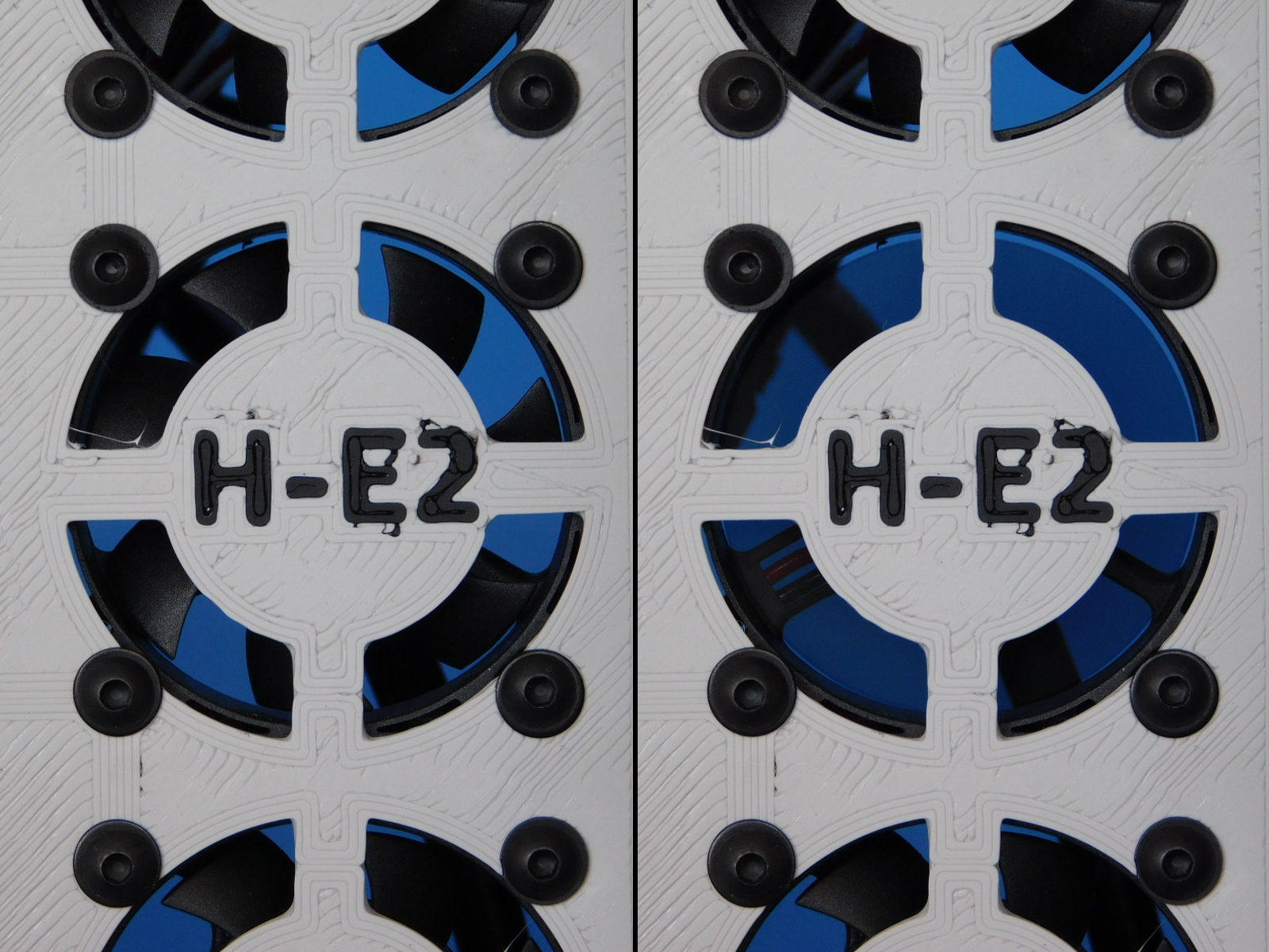
The fan on the right panel of the CB Test Stand labeled ”H-E2” should now turn on.
If the fan did not turn on the unit has failed the test and should be returned to an ESD Safe workspace for diagnosis and repair.
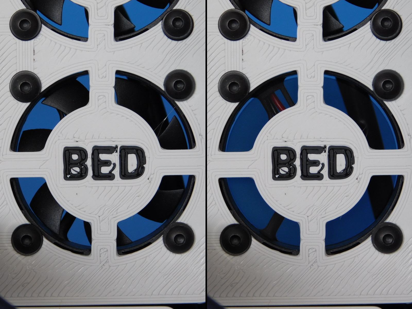
The fan on the right panel of the CB Test Stand labeled ”BED” should now turn on.
If the fan did not turn on the unit has failed the test and should be returned to an ESD Safe workspace for diagnosis and repair.
If the unit completes the test gcode, a happy tune will play.
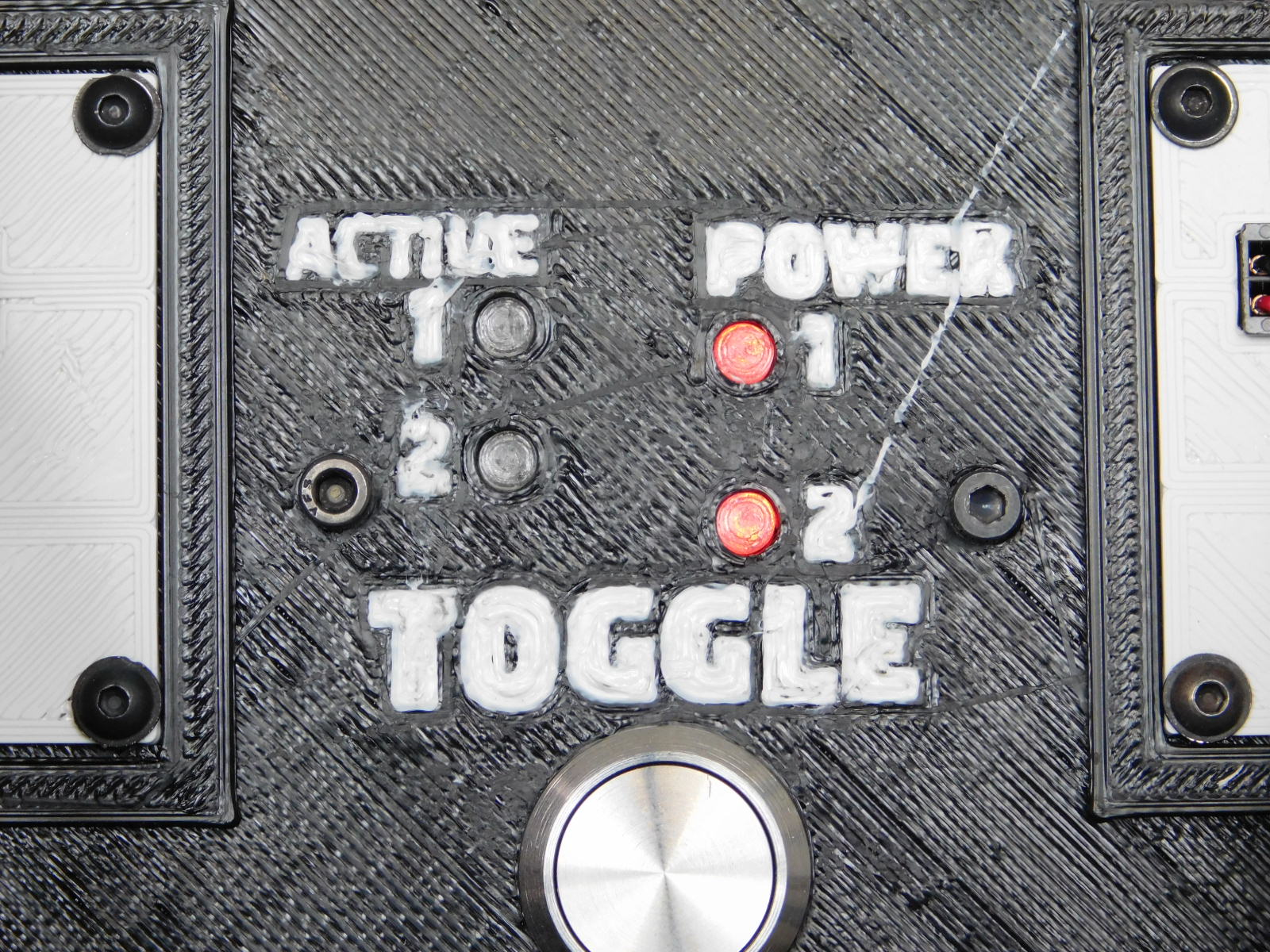
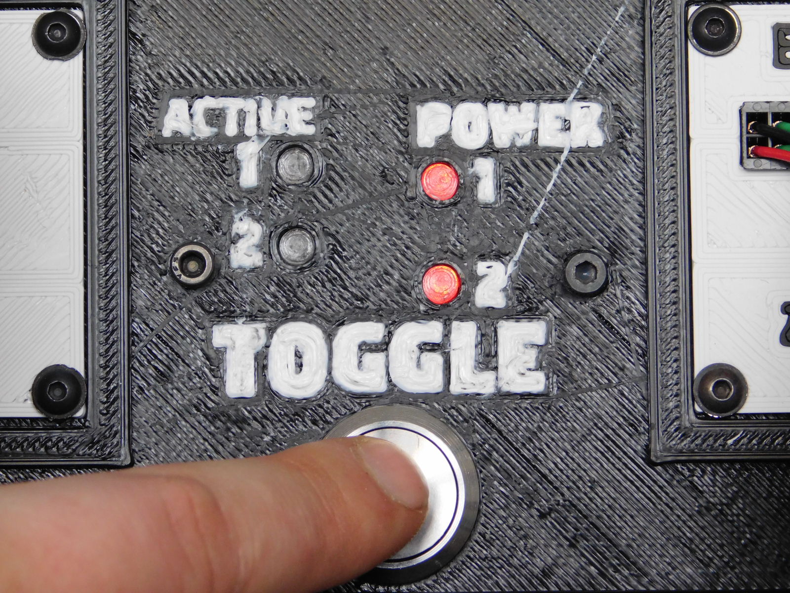
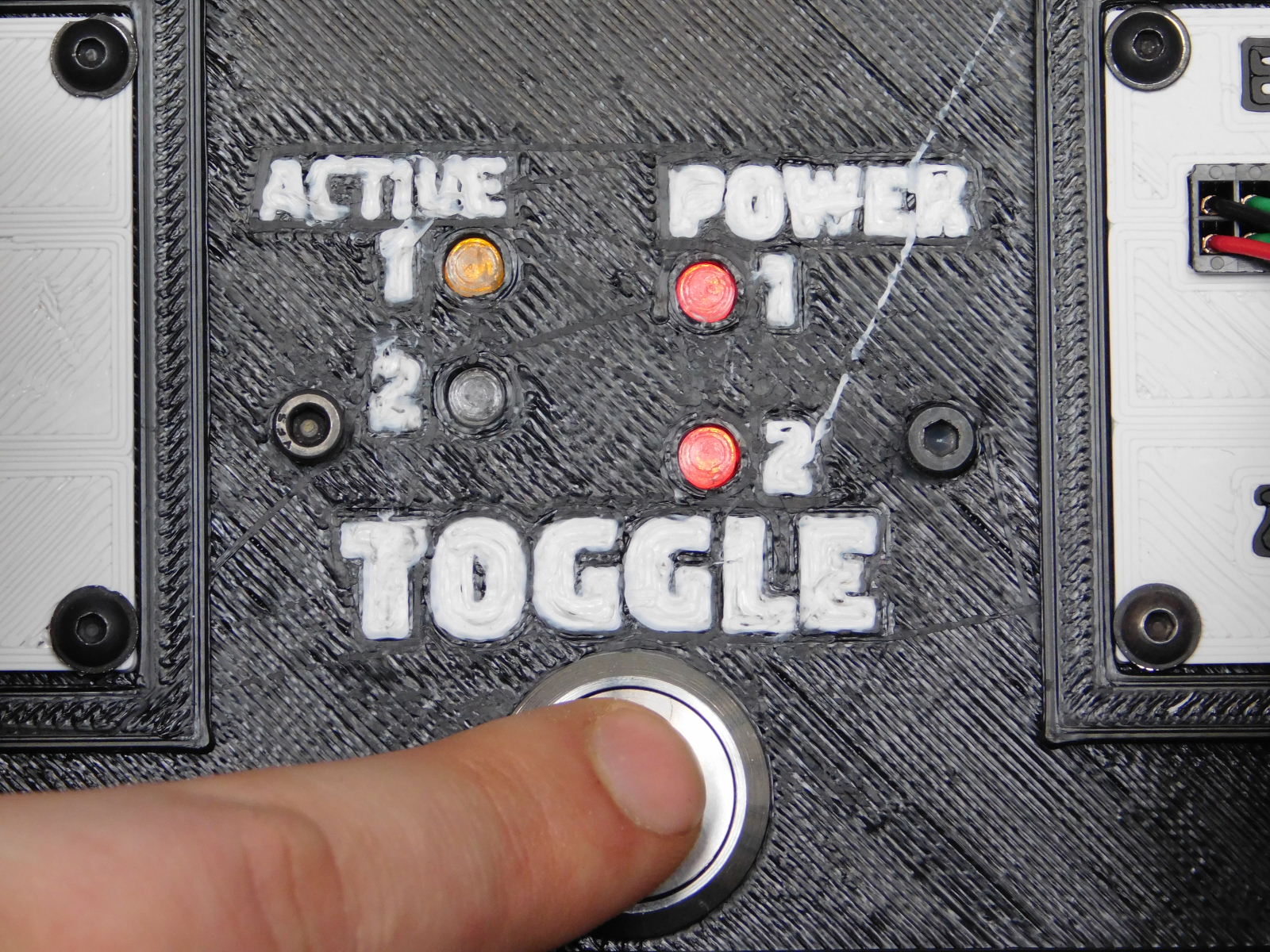
In the center of the upper panel of the test stand is used for testing the filament sensor harness function and the related functions of the Archim.
First, verify that both lights labeled “POWER” are lit, this indicates that the filament sensor harness is made and connected correctly, and the test module is receiving 3.3v from the Control Box Assembly.
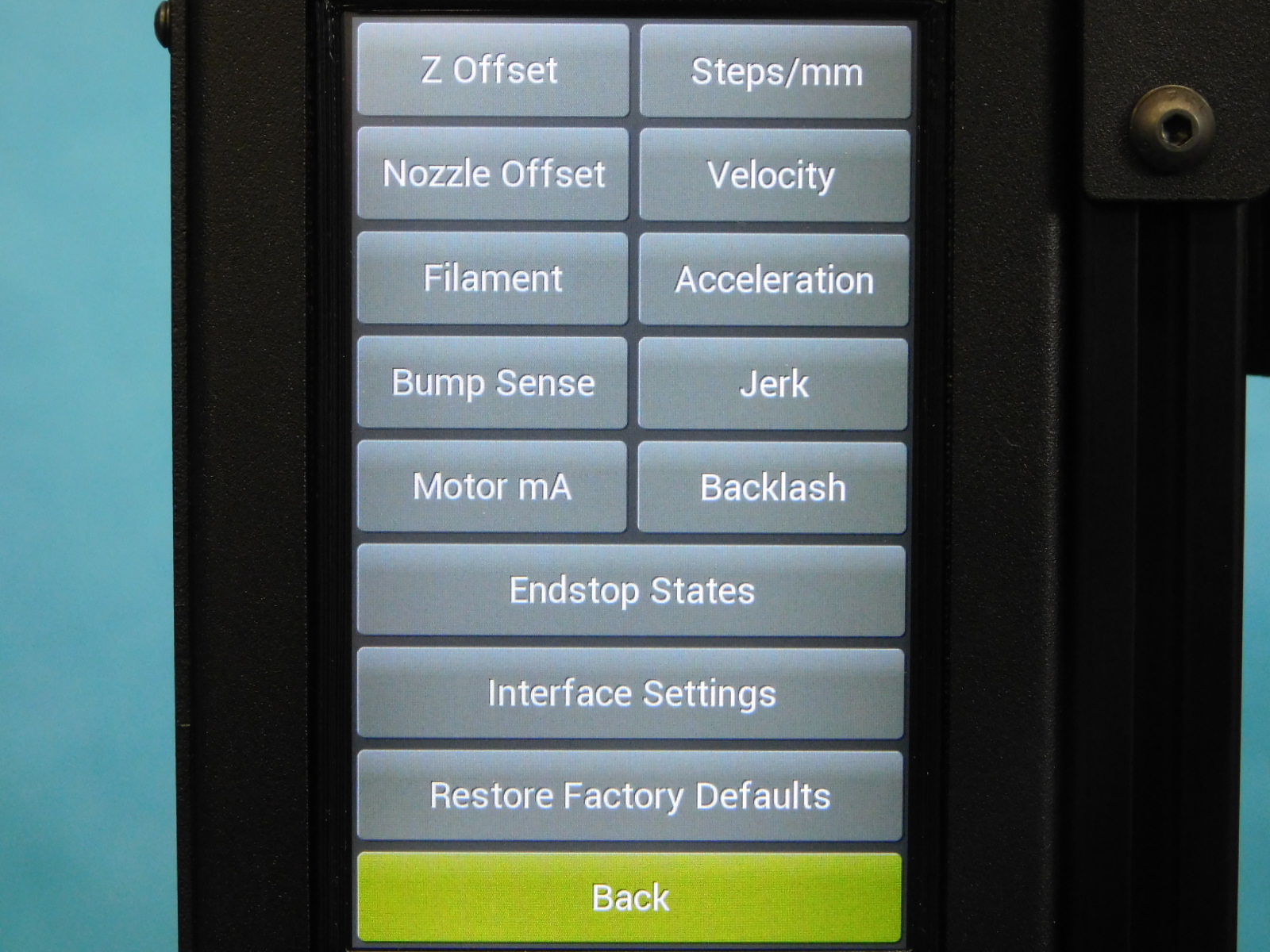
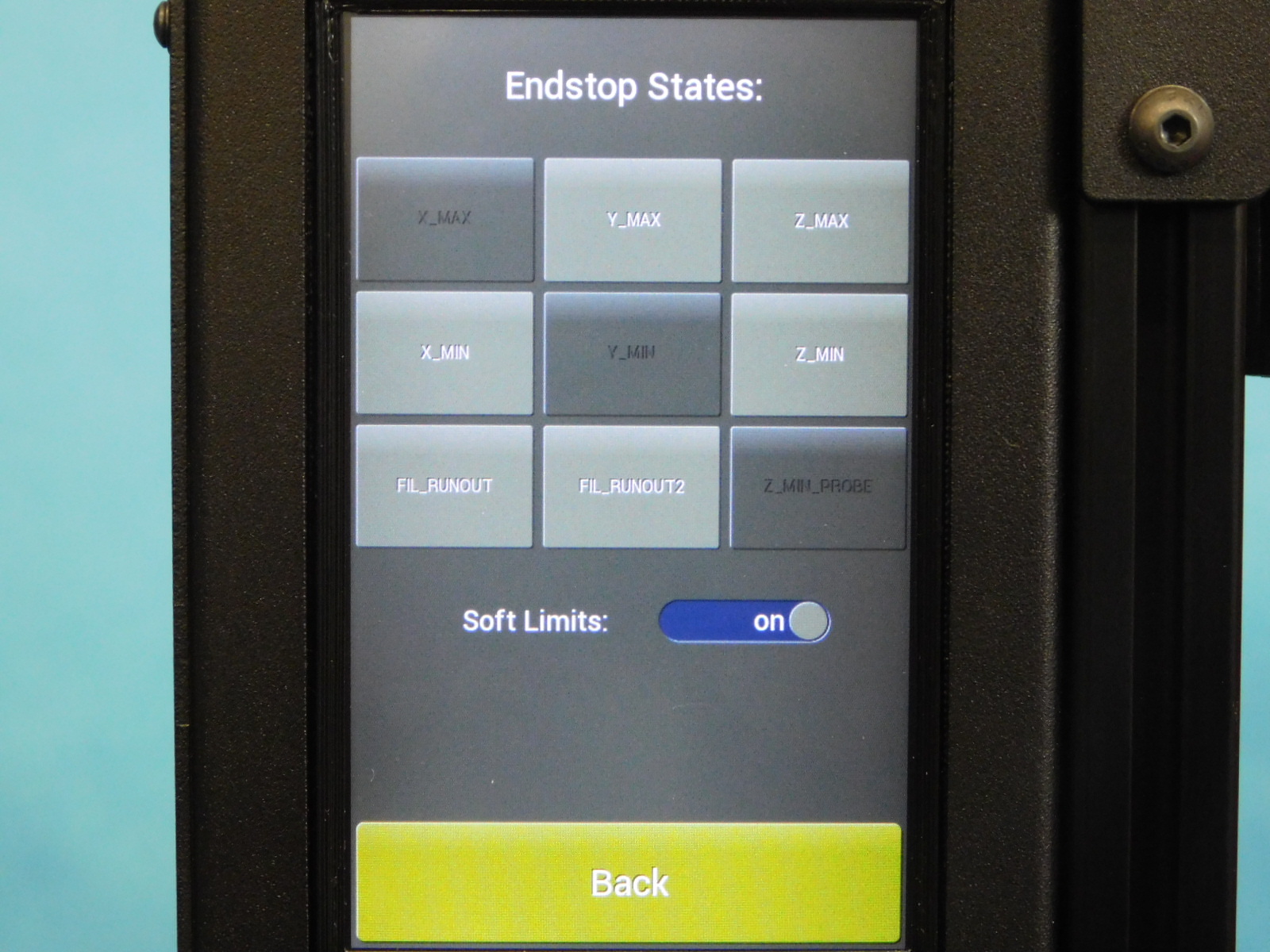
Navigate to the "Endstop States" menu in the LCD: Menu>Advanced Settings> Endstop States
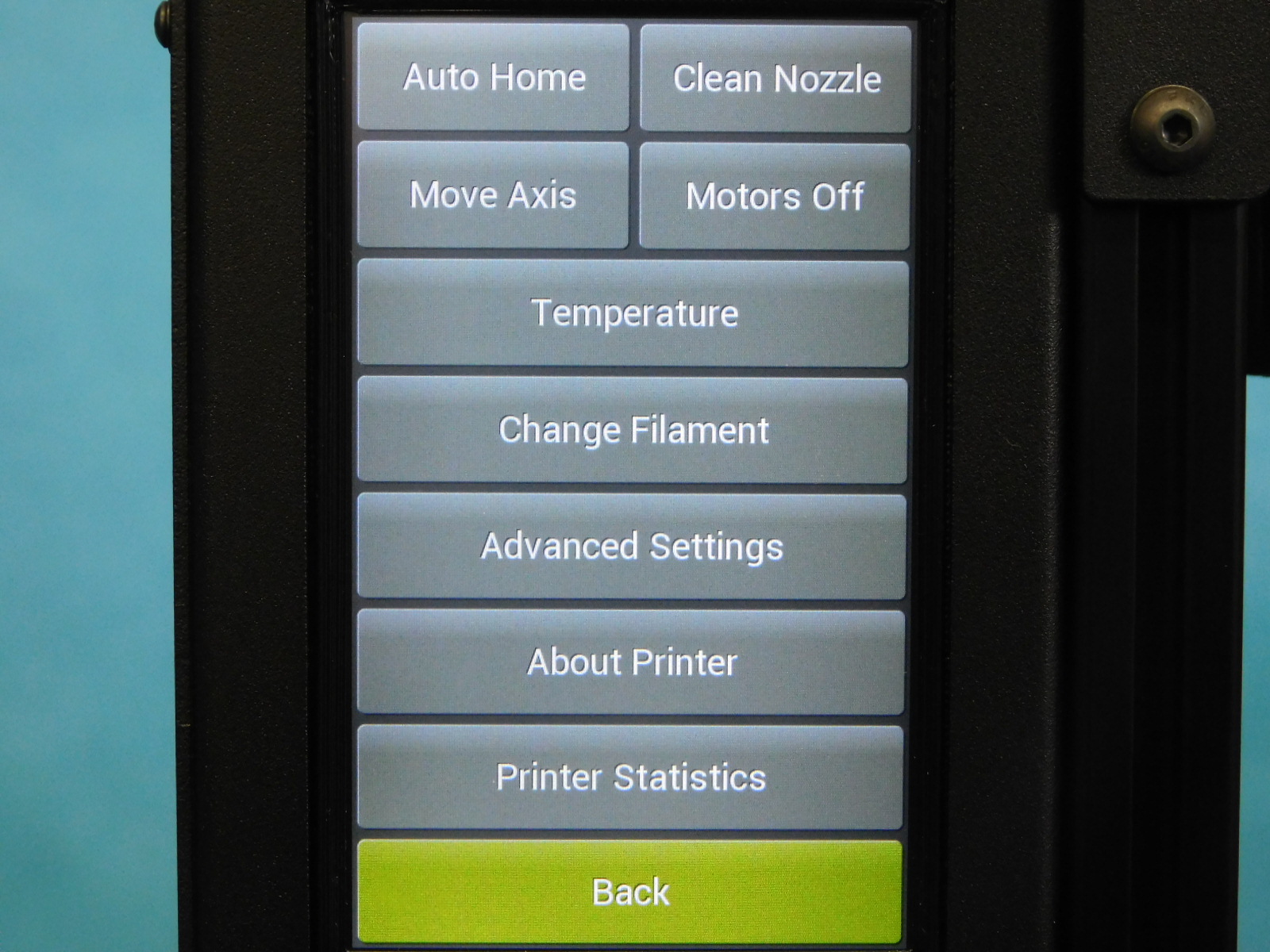
On the LCD, touch “Endstop States”
In the lower left corner is the filament sensor status.
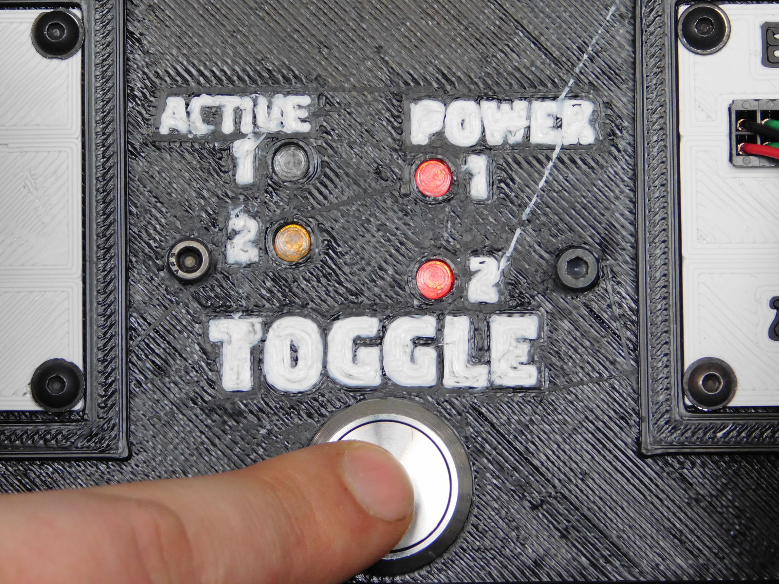
Press the “TOGGLE” button on the Control Box Test Stand
Verify that the light flashing corresponds with the correct section flashing on the control box.
If light “1” is flashing on the test stand, FIL_RUNOUT should be flashing on the LCD.
If light “2” is flashing on the test stand, FIL_RUNOUT2 should be flashing on the LCD.
Continue to toggle through the modes;
Power on mode: no pulse
1st mode: pulse number 2
2nd mode: pulse number 1
3rd mode: pulse both together
4th mode: pulse both alternately
5th mode: both ON
6th press returns to no pulse
If the incorrect light flashes or either of the POWER LEDs have failed to illuminate, the unit has failed testing and must be returned to an ESD safe work area for diagnosis and repair.
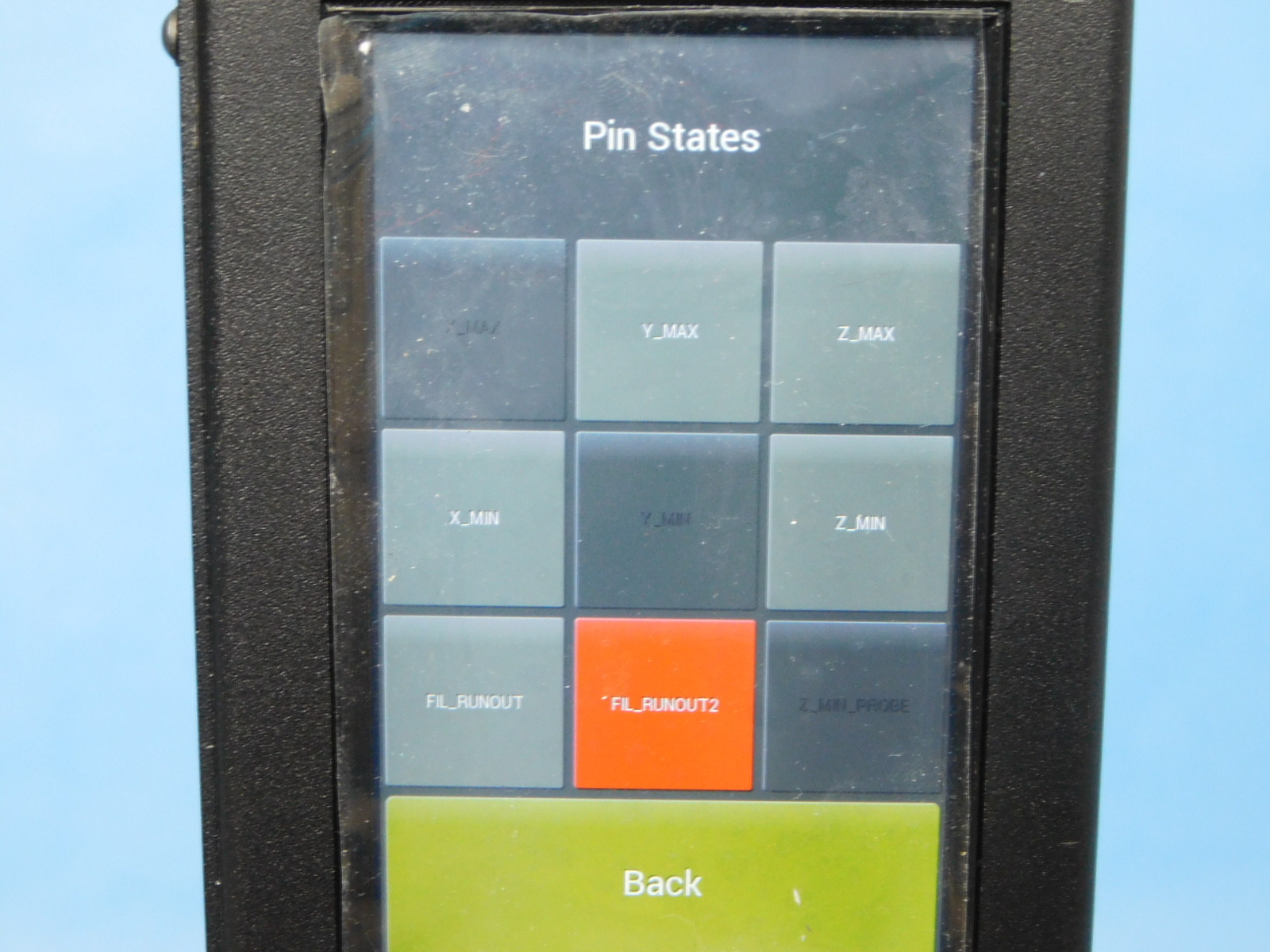
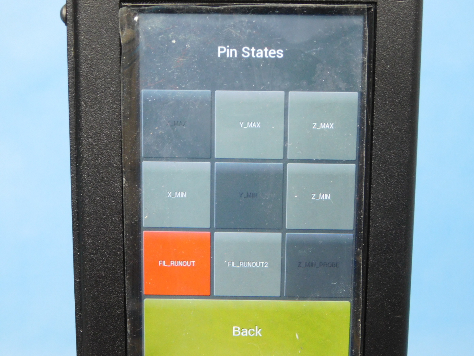
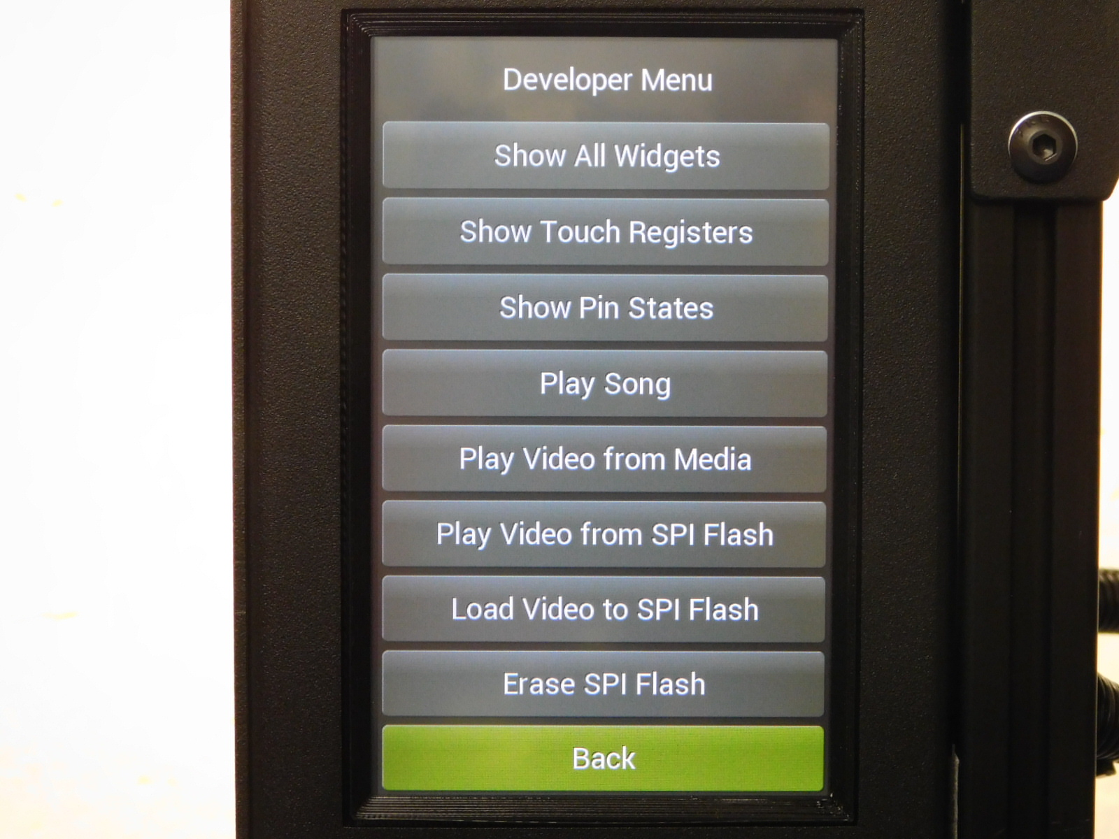
From the Pin States screen, press the "Back" button to return to the Development Menu
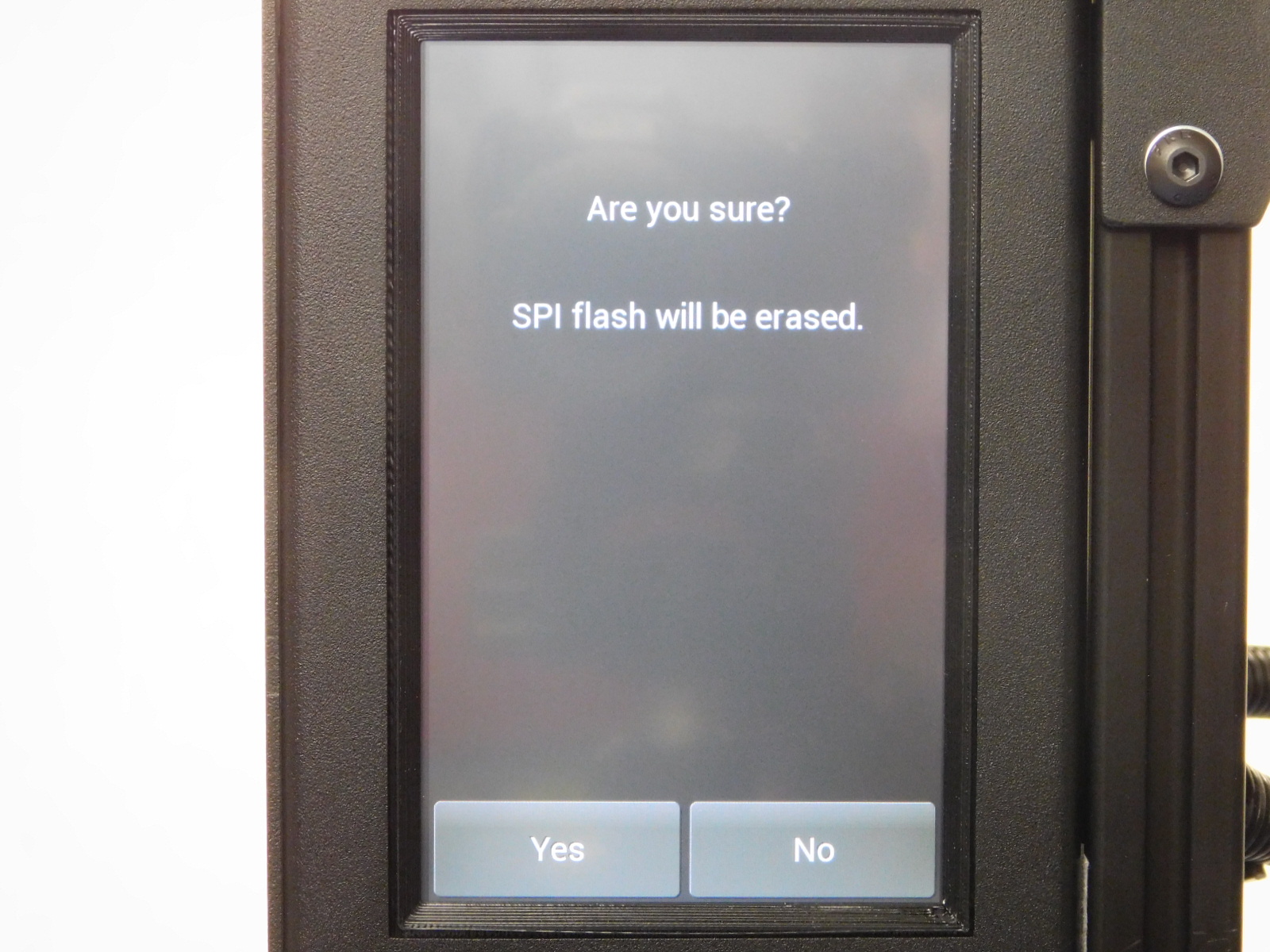
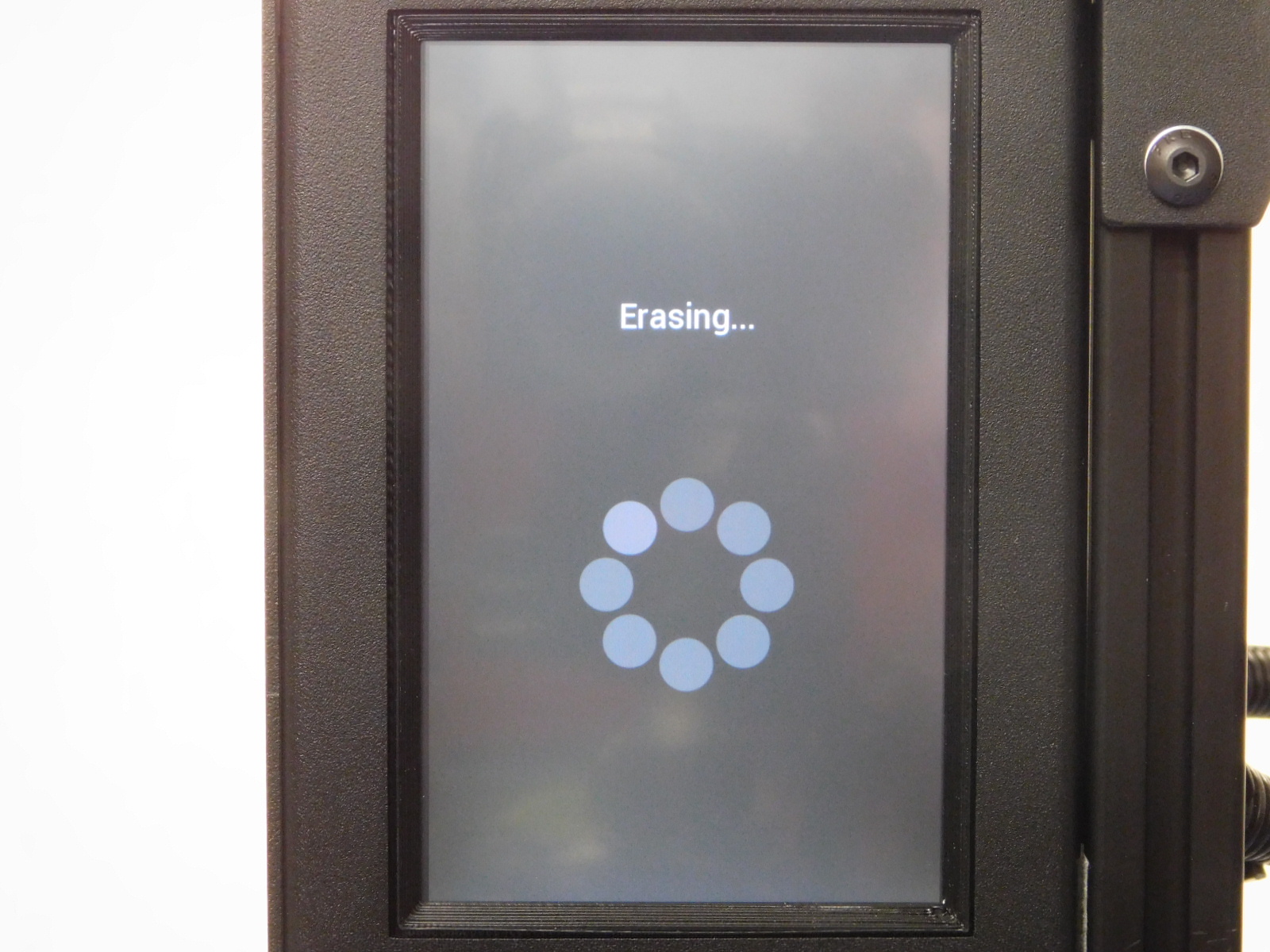
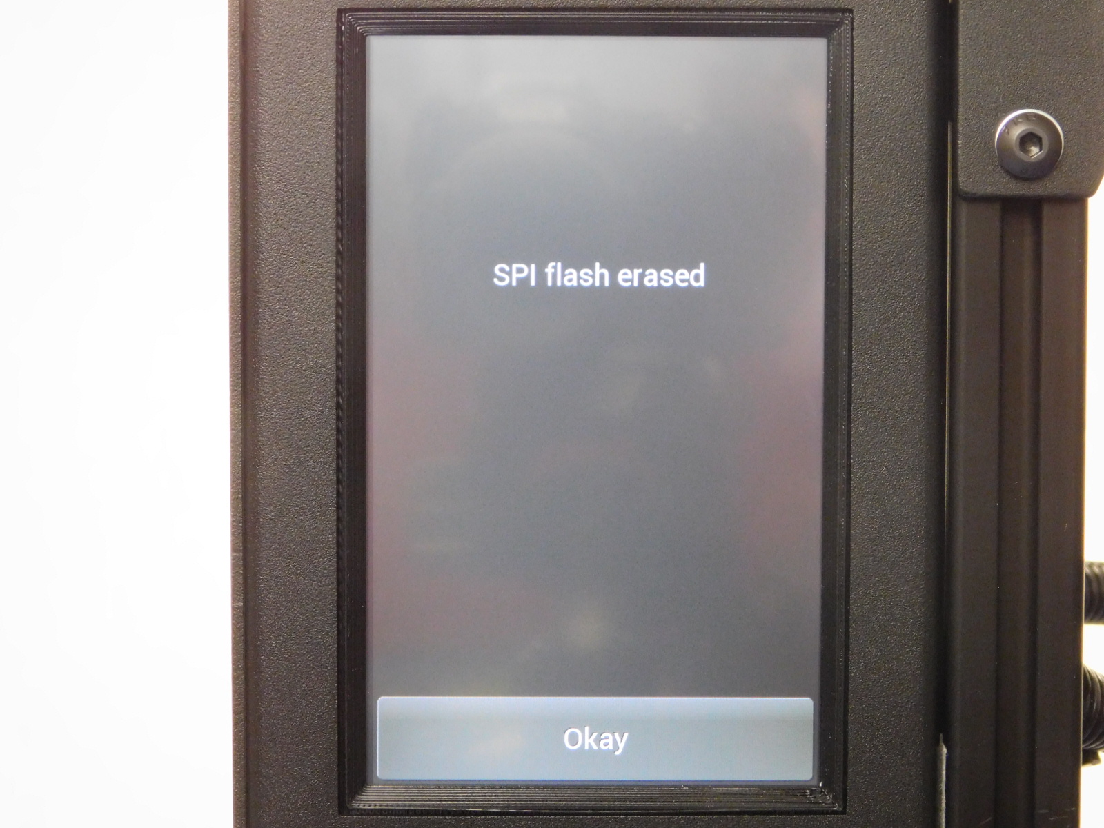
Select "Erase SPI Flash" and "Yes" on the next screen
Wait for the process to finish and select "Okay"
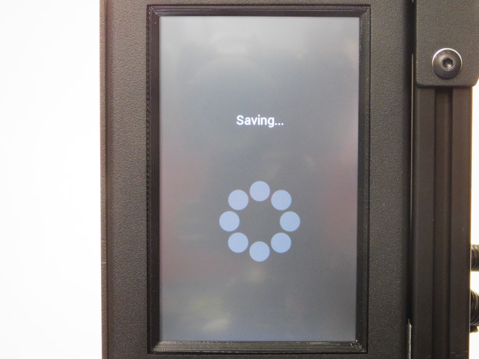
Now select "Load video to SPI Flash"
Wait for the process to finish, it takes about 90 seconds
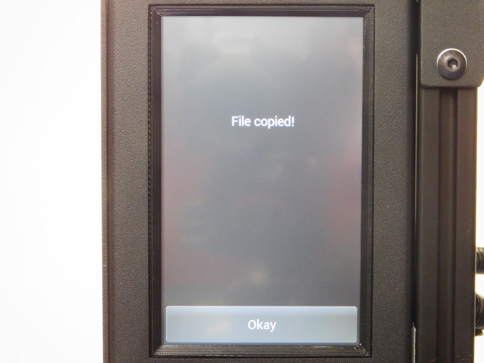
The display will report "File copied"
Select "Okay" > "Back" > "Okay" to return to the menu
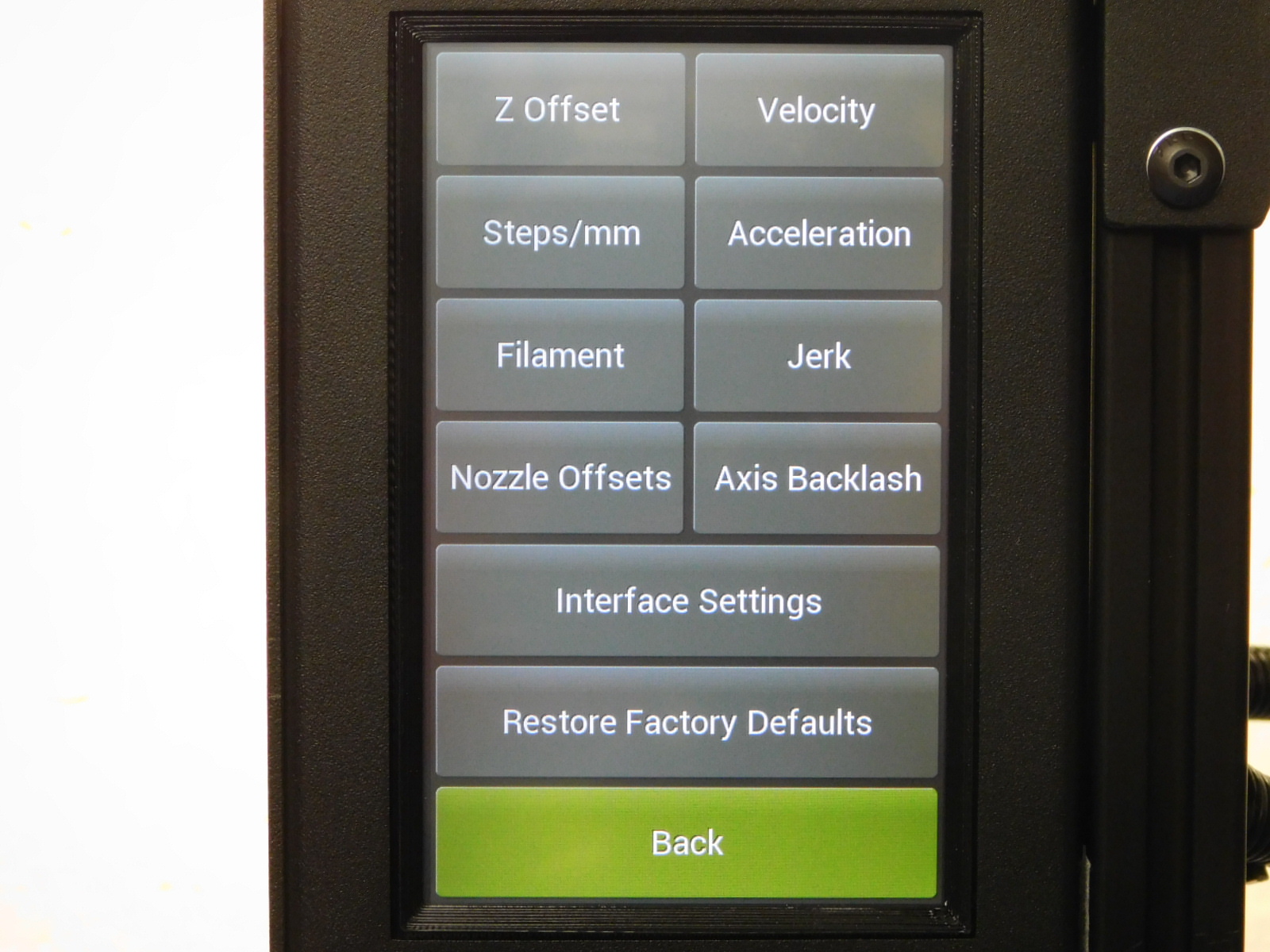
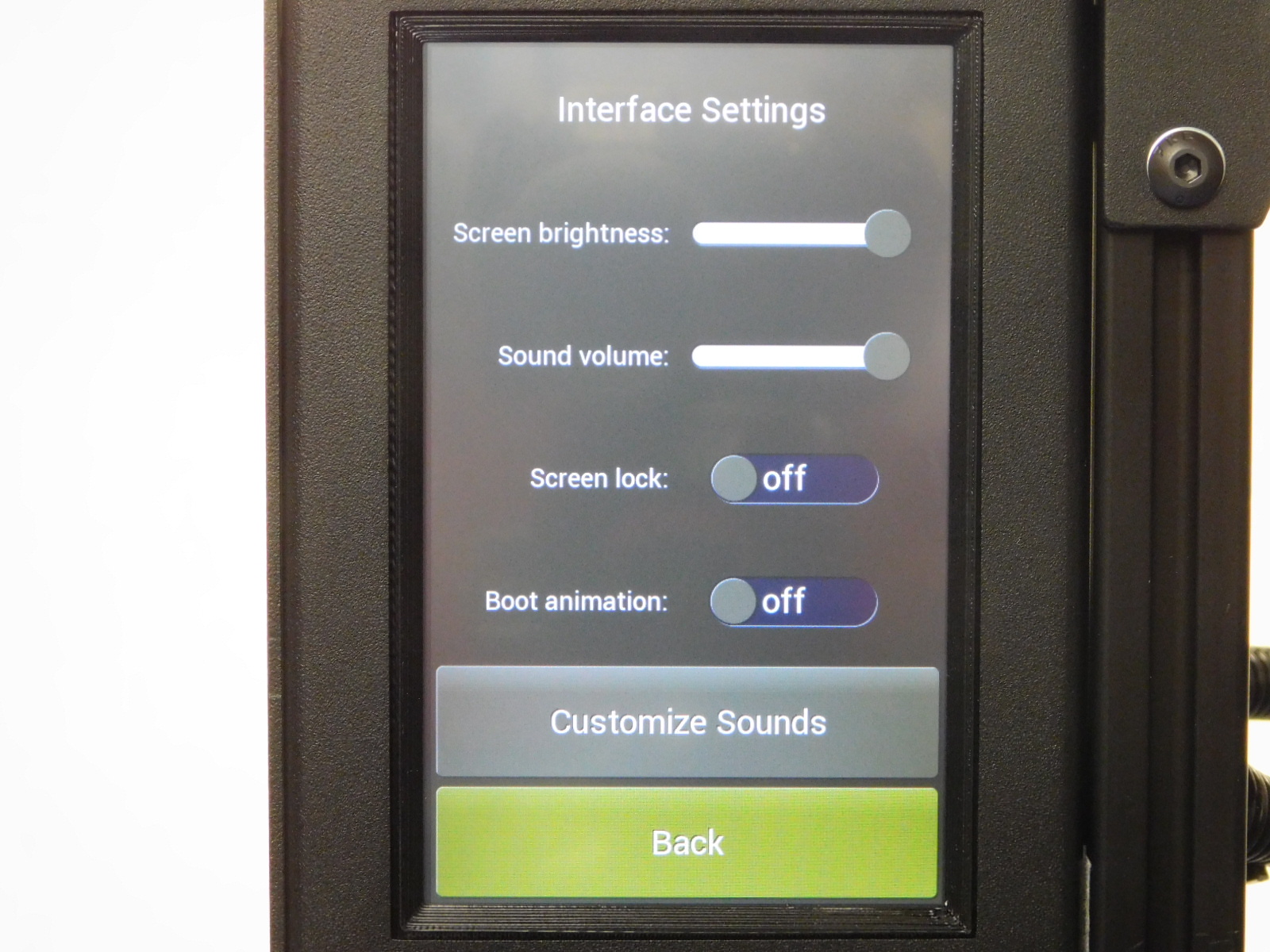
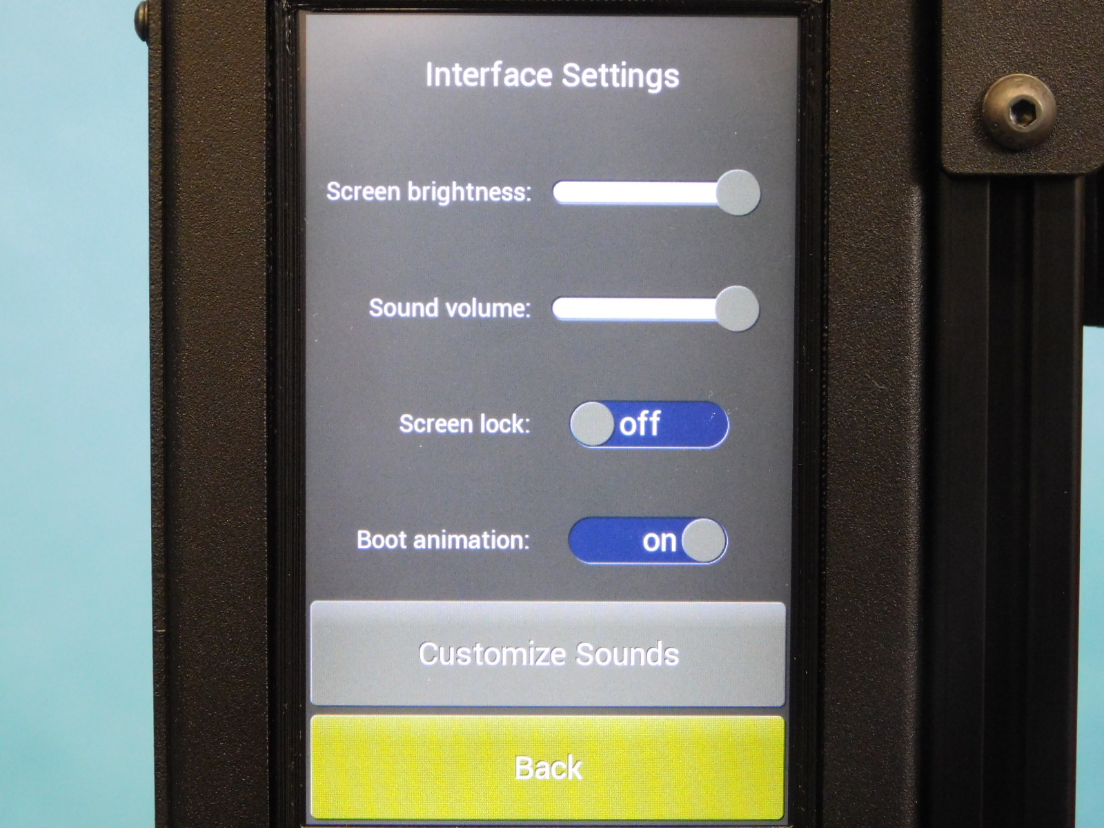
Now activate the boot animation by selecting "Advanced Settings" > "Interface Settings" and toggle "boot animation" to ON
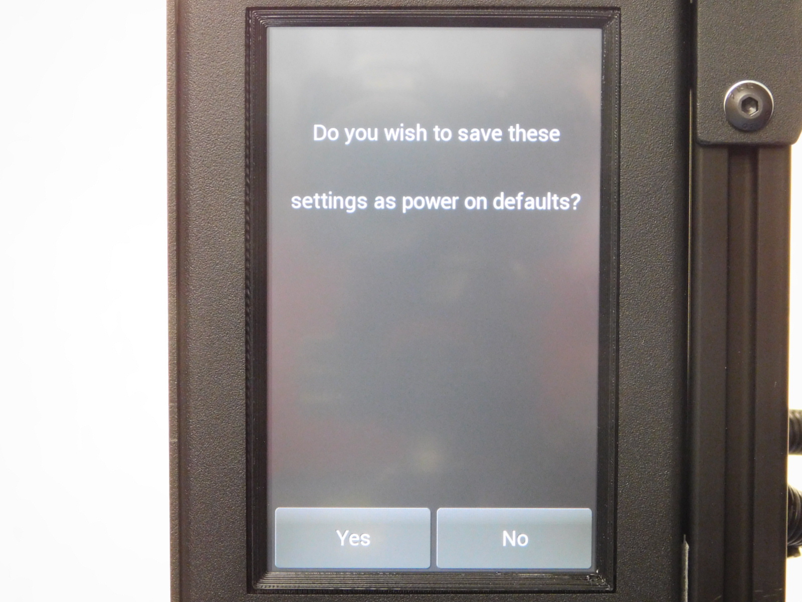
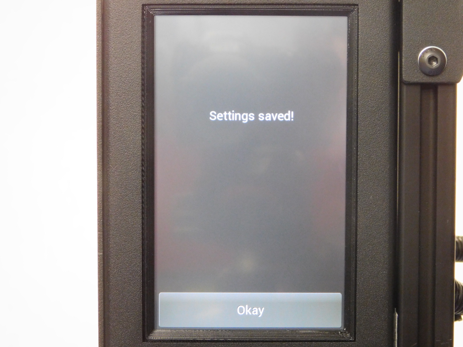
Hit "Back" TWICE followed by "Yes" to save the settings and confirm with "Okay"
Power the unit off and then back on to test the boot animation


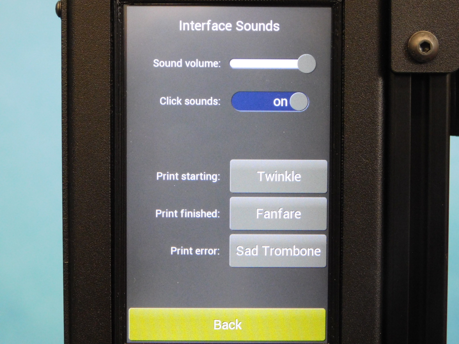
After the machine has powered back on and displayed the boot animation, navigate back to interface settings and select "Customize sounds"
Menu > Advanced Settings > Interface settings > customize sounds
Set the options in the menu to the following:
Click sounds on
Print Starting: Twinkle
Print Finished: Fanfare
Print Error: Sad Trombone
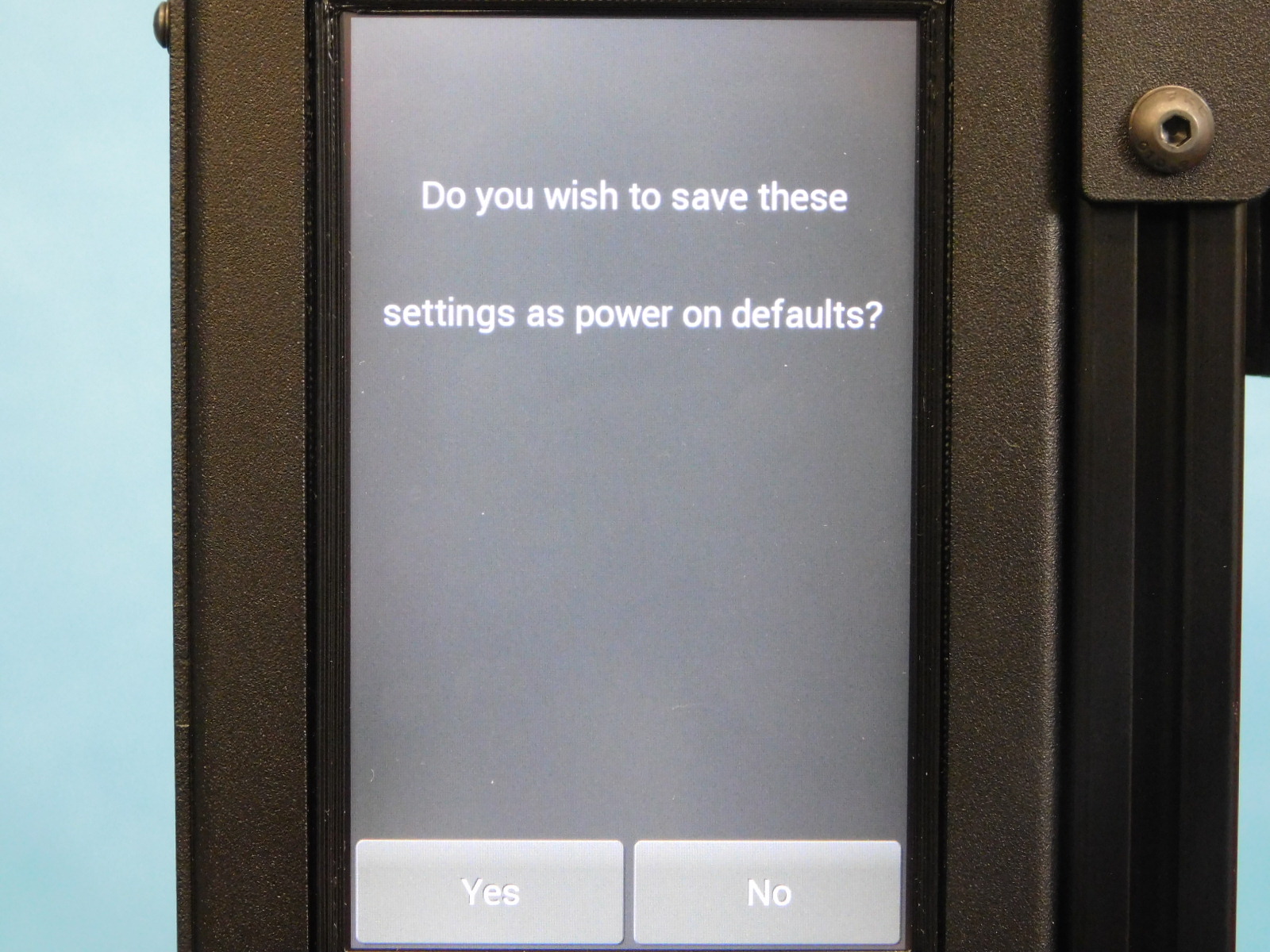
Navigate back to the main screen, saving settings when prompted.


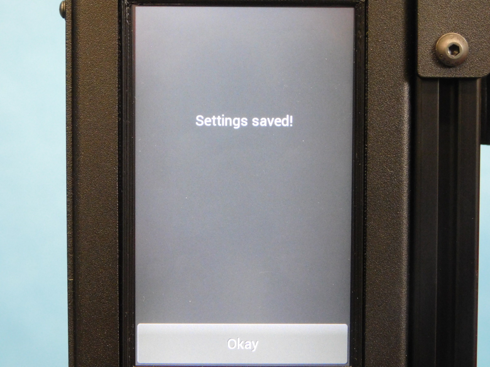
Power off the unit
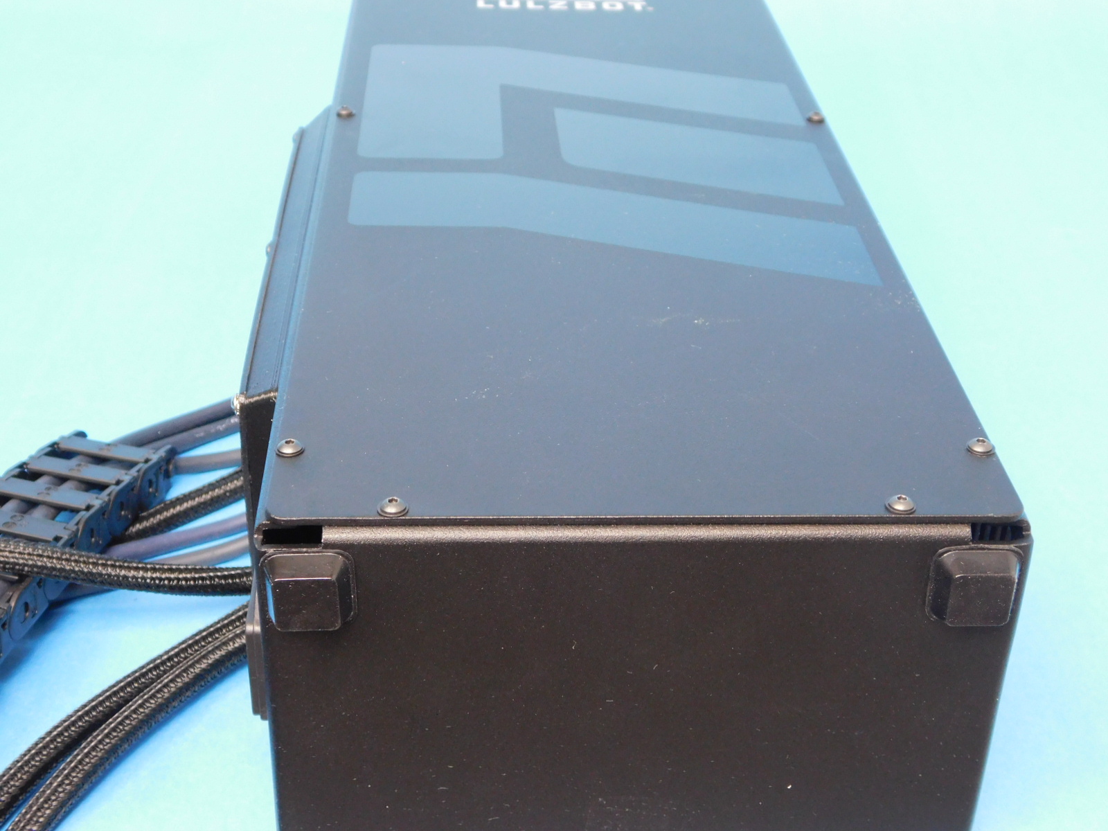
Carefully disconnect the unit from the test stand
Lay the assembly down on a clean surface
Install two rubber feet [HD-MS0363] to the bottom of the chassis at the corners shown.
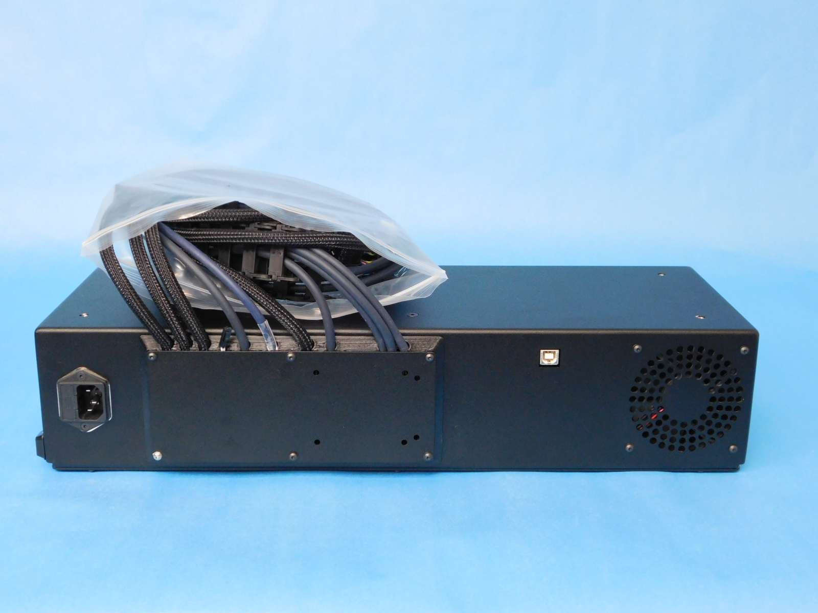
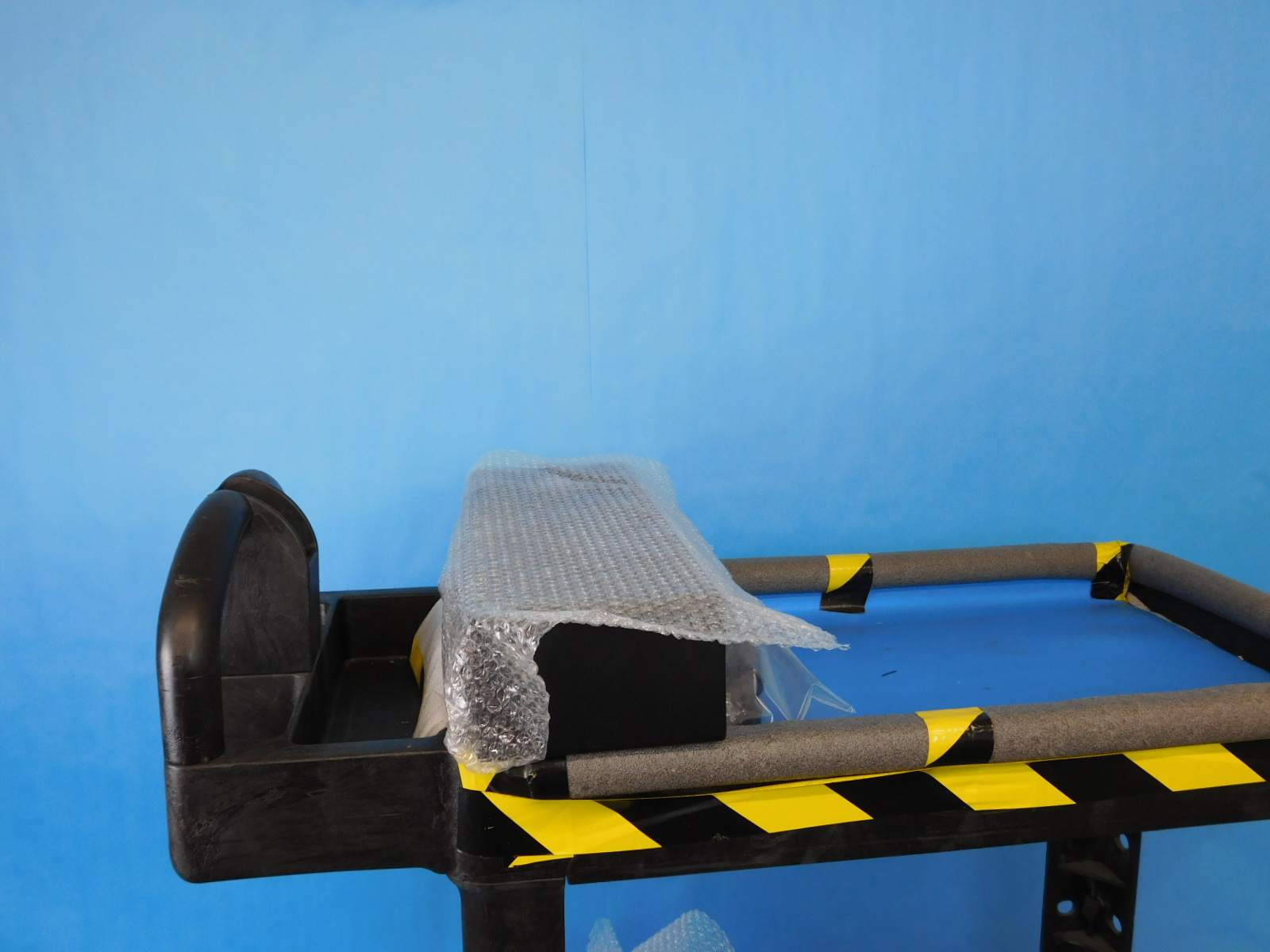
For transit between work areas:
Loop the cables, put a bag over them, then wrap the whole thing in bubble wrap and place it on the cart of passed tested units.
Nicely done!