Open HardwareAssembly Instructions
Guides for installation and assembly of the LulzBot line of products made by FAME 3D LLC.
Guides for installation and assembly of the LulzBot line of products made by FAME 3D LLC.
1x- [EL-FA0061] CB Case Fan
1x- [EL-HR0140] Bed Harness, Assembled
1x- [EL-HR0141] Extruder X Harness, Assembled
1x- [EL-HR0143] Y/Z Harness, Assembled
1x- [EL-HR0144] Filament Sensor Harness, Assembled
2x- [EL-HR0147] LCD/USB Harness
1x- [EL-HR0148] CB Bed Power Harness
1x- [EL-HR0150] CB Z Endstop Harness, Assembled
1x- [EL-HR0151] CB X Harness
1x- [EL-HR0152] PSU to Ground Green
1x- [EL-HR0153] CB Extruder Harness
1x- [EL-HR0154] CB DC Power Harness
1x- [EL-HR0156] Erase Switch Harness
1x- [EL-HR0157] CB Switch to PSU Harness, Assembled
1x- [EL-HR0167] Plug to Ground Green
1x- [EL-HR0168] Plug to Switch, Black and White
1x- [EL-HR0183] CB YZ Harness
1x- [EL-HR0184] CB Bed Harness
1x- USB Reader Assembly
1x- Touchscreen Assembly
1x- [EL-MS0346] MOD PWR ENTRY INLET W/FUSE
1x- [EL-MS0535] USB ESD Sheilding fingers
1x- [EL-PS0031] Mean Well Switching Power Supplies 500W 24V 21A
1x- [EL-SW0023] SWITCH ROCKER DPST 20A 250V, Illuminated Red
5x- [HD-MS0058] Wire Tie 8", Black
2x- [HD-MS0463] Insul-Fab Fujipoly Thermal Gap Filler, Strip
5x- [HD-MS0571] Pre-Cut Adhesive Square
1x- [PC-BD0113] Archim 2.2b PCBA
1x- [PP-FP0149] TAZ Electronics Chassis, HD, Touchscreen, Quiver
1x- [PP-FP0150] TAZ Electronics Cover, Quiver
1x- [PP-FP0153] TAZ Interconnect Cover, Quiver
1x- [PP-GP0382] USB Bezel
1x- [PP-GP0384] LCD Bezel
1x- [PP-GP0389] Heatsink Mount
1x- [PP-GP0407] Interconnect Housing
5x- [PP-GP0483] Universal Cable Tie Mount
1x- [PP-MP0234] Archim Board Heat Sink
9x- [HD-BT0104] M3 x 8 Bolt, BHCS, SST
2x- [HD-BT0116] M3 x 10 Bolt, FHCS Black-Oxide
4x- [HD-BT0128] M3 x 6 Bolt, FHCS Black-Oxide
5x- [HD-BT0137] M3 x 8 Bolt, BHCS, Black-Oxide
10x- [HD-BT0140] M3 x 6 Bolt BHCS, Black-Oxide
5x- [HD-BT0155] M4 x 6 FHCS, Black-Oxide
4x- [HD-BT0171] M3 x 20 Bolt BHCS, Black-Oxide
1x- [HD-BT0234] M3 x 10 Stainless BHCS
6x- [HD-NT0001] M3 Nyloc Nut
3x- [HD-WA0035] External Serrated Lock Washer, M3
19x- [HD-WA0038] M3 Washer, Black-Oxide
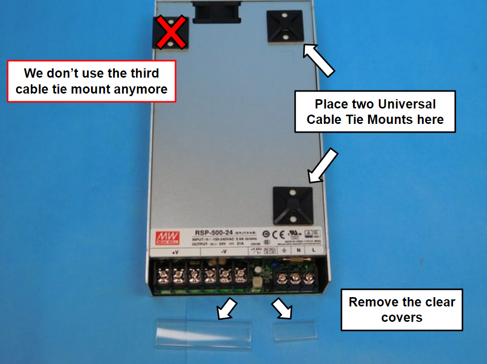
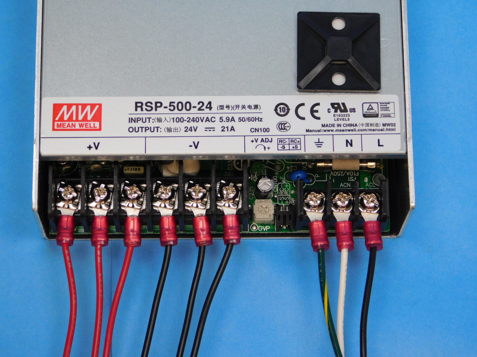
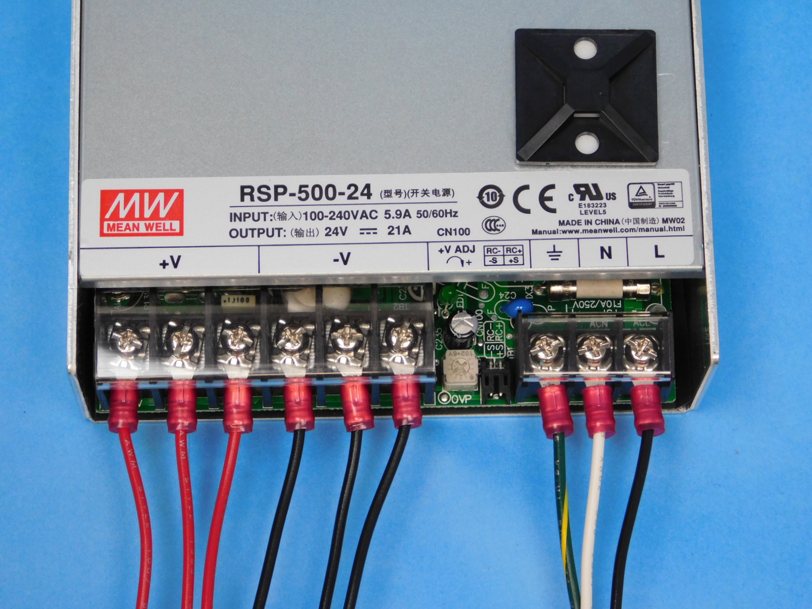
Use 2x universal cable tie mounts [PP-GP0483] and 2x pre-cut adhesive squares[HD-MS0571] and place them on the top surface of the power supply [EL-PS0031] at each arrow, as pictured.
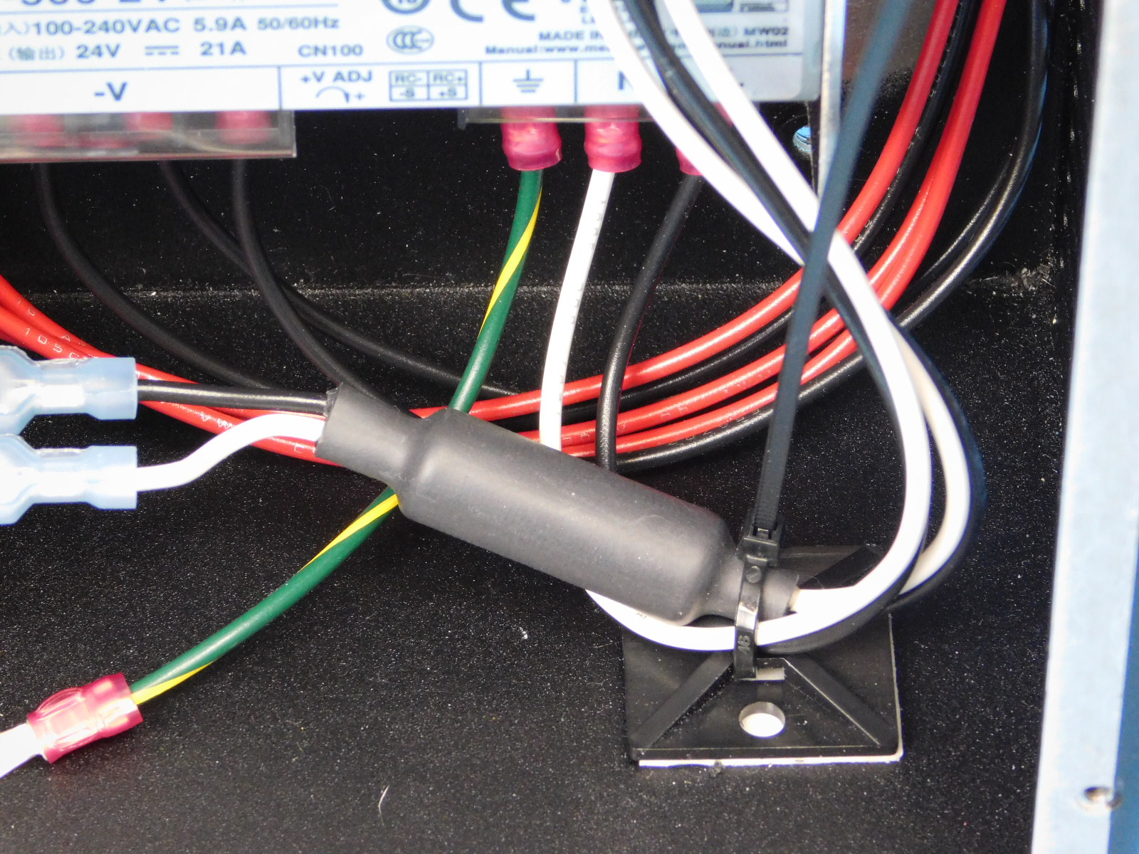
Then remove both of the clear terminal shields to gain access to all 9 screw terminals.
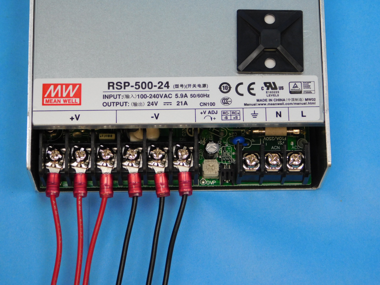
Connect CB DC Power Harness [EL-HR0154] to the power supply;
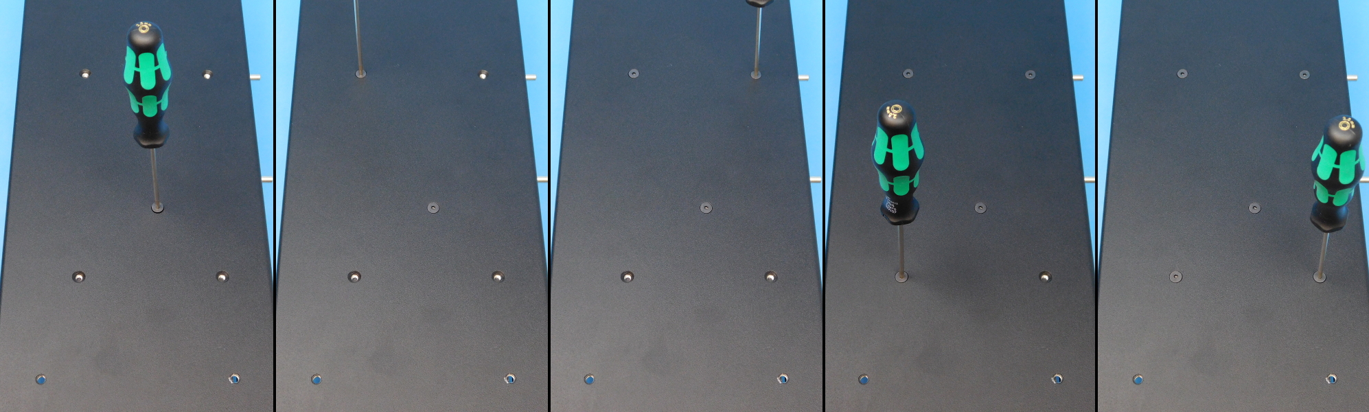
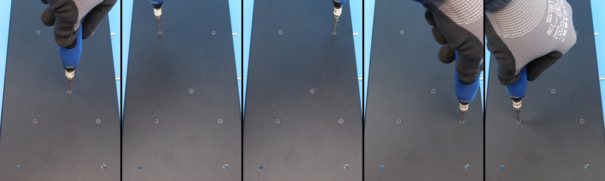
Using a P2 phillips screwdriver loosen the screw terminals until the fork terminals can be inserted, (3 red (+3) and 3 black (-3)) to power supply.
Secure screws to finger tight then ¼ turn past.
Ensure the black leads are connected to the terminals marked “-V” and the red leads are connected to the terminals marked “+V”.
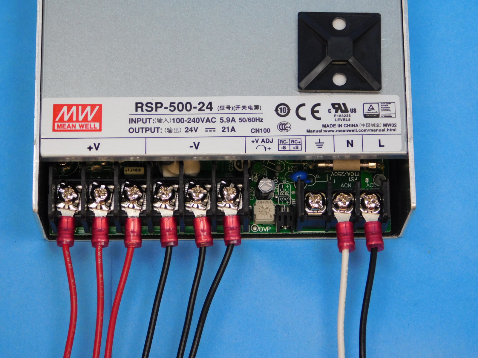
Connect CB Switch to PSU Harness [EL-HR0157]
Secure the black lead in the terminal labeled “L”
Secure the white lead in the terminal labeled “N”
Secure screws to finger tight then a ¼ past.
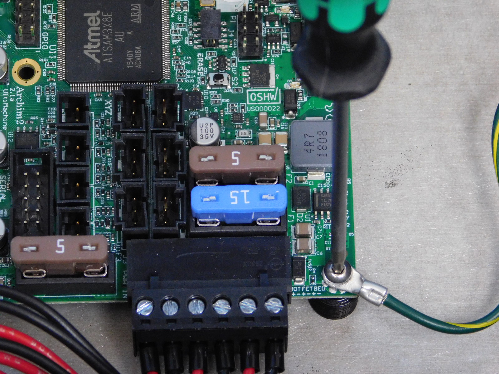
Connect PSU to Ground Green [EL-HR0152] to the power supply ground terminal.
Secure screws to finger tight then a ¼ past.
Replace the two clear terminal shields to their original location.
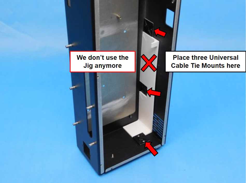
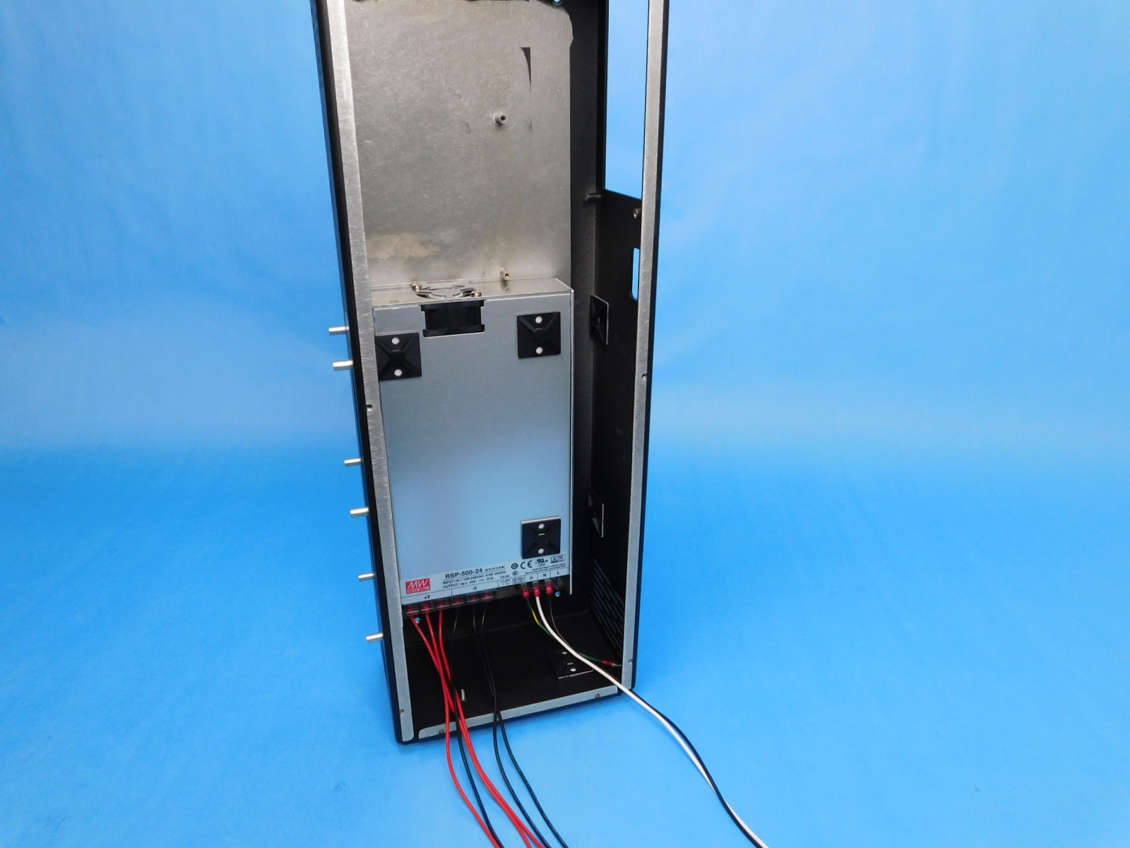
Use 2x universal cable tie mounts [PP-GP0483] and 2x pre-cut adhesive squares[HD-MS0571] and place them inside the electronics chassis [PP-FP0149]**, one on the bottom of the case, and two along the inner front edge, as pictured.
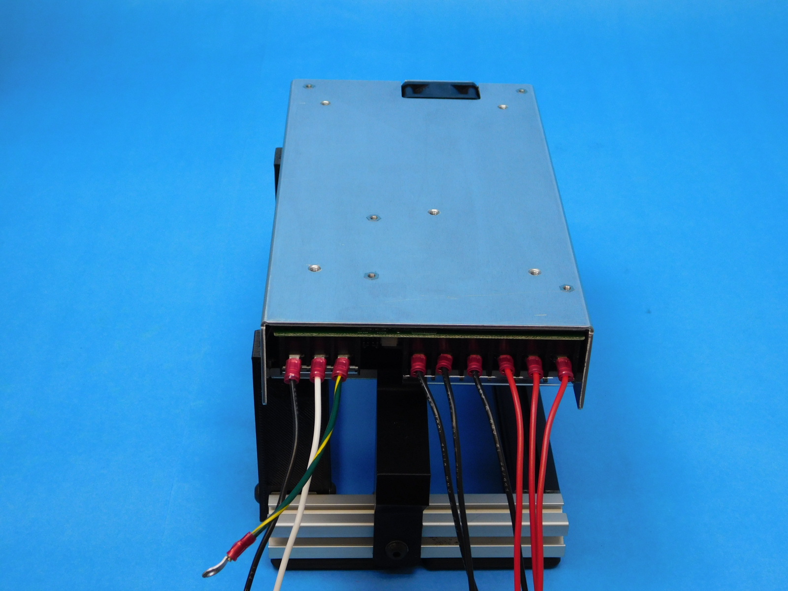
Place the prepared power supply from the previous step on the stand jig as pictured, carefully place the electronics chassis over the power supply with the bottom facing you, line up the fastener holes of the case with the fastener holes of the power supply.
Secure using 5x M4x6 FHCS [HD-BT0155], torque to 5in*lbs
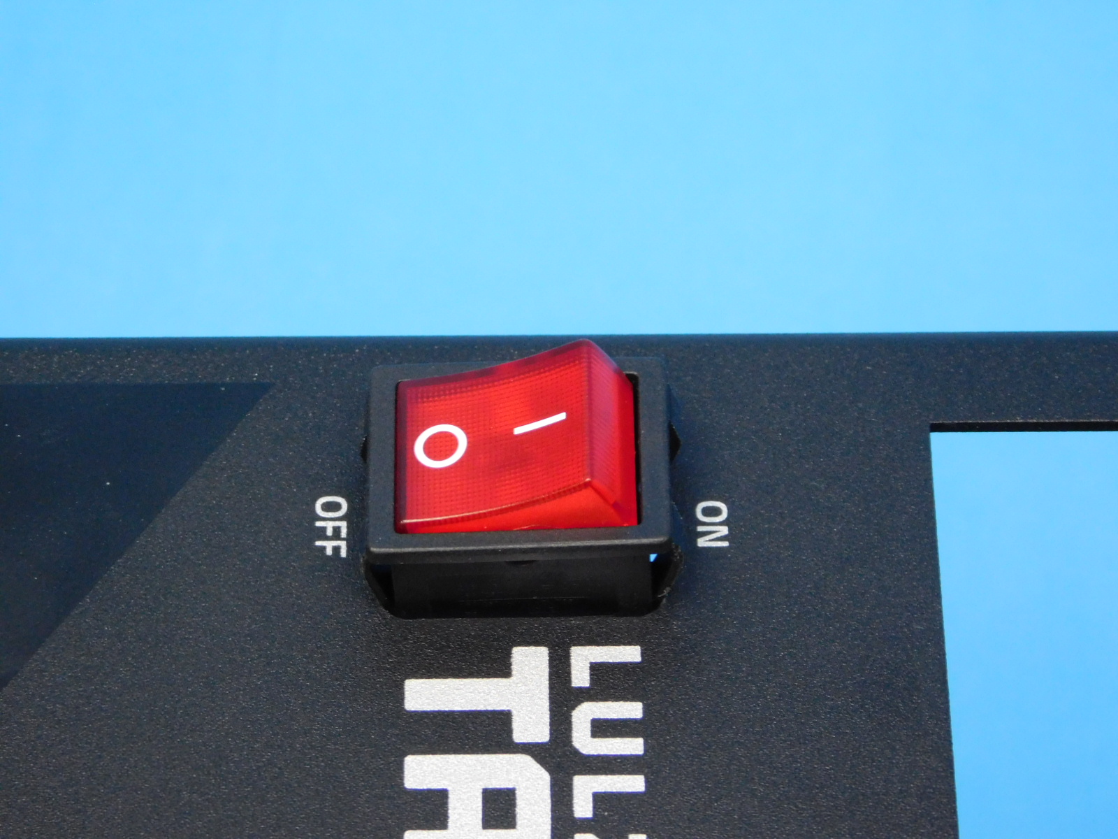
Install one Power Switch [EL-SW0023] into the slot on the front of the chassis [PP-FP0149] with the “I” facing the “ON” label on the chassis. The rocker switch will press in from the front of the case and be held by the clips on the top and bottom of the switch.
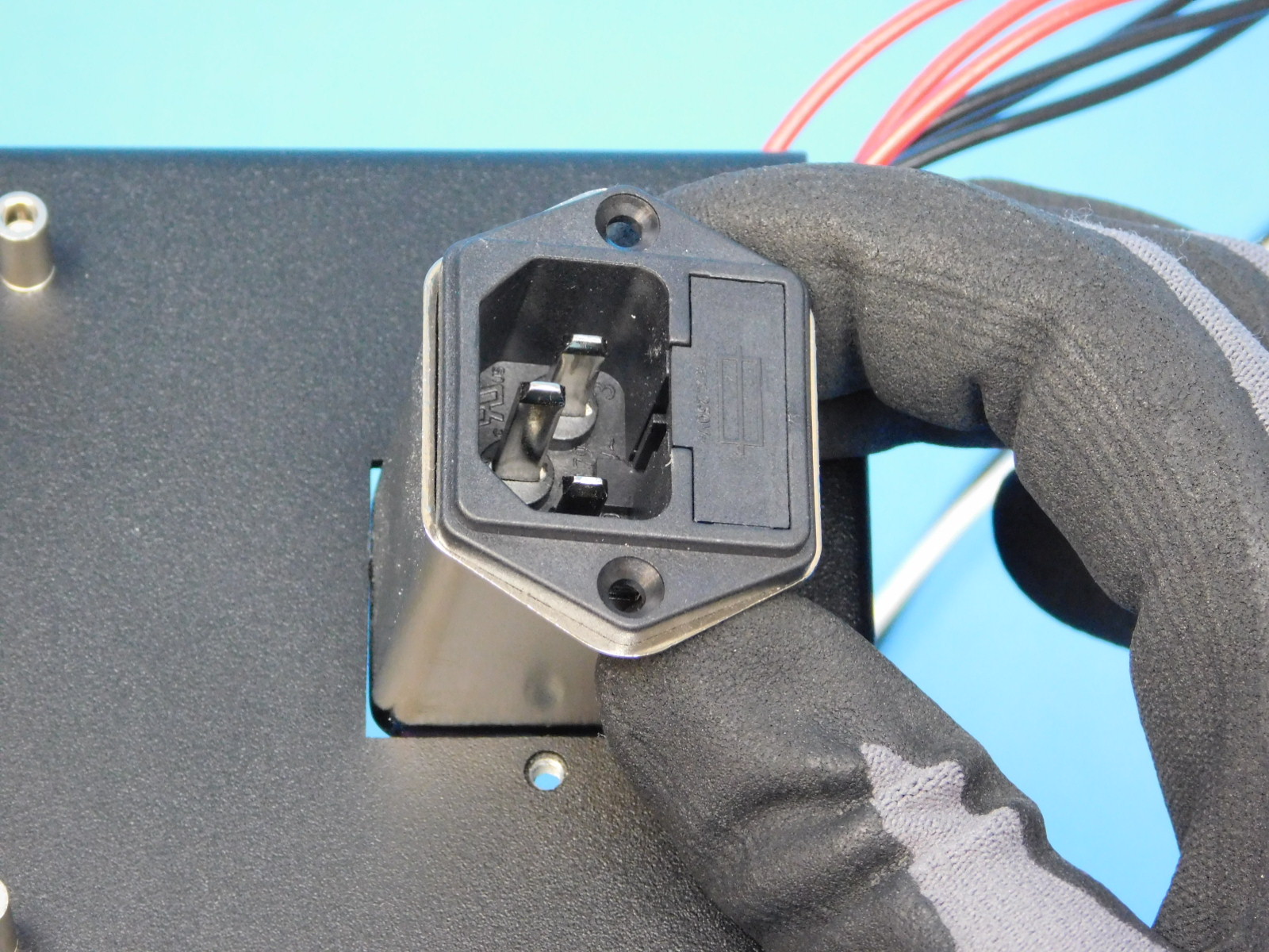
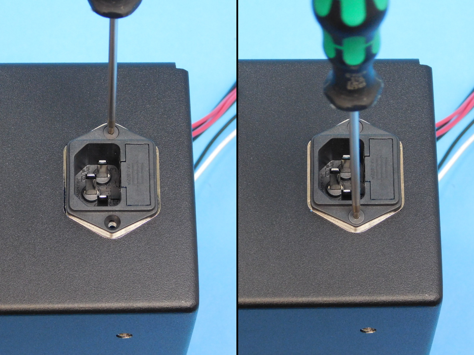
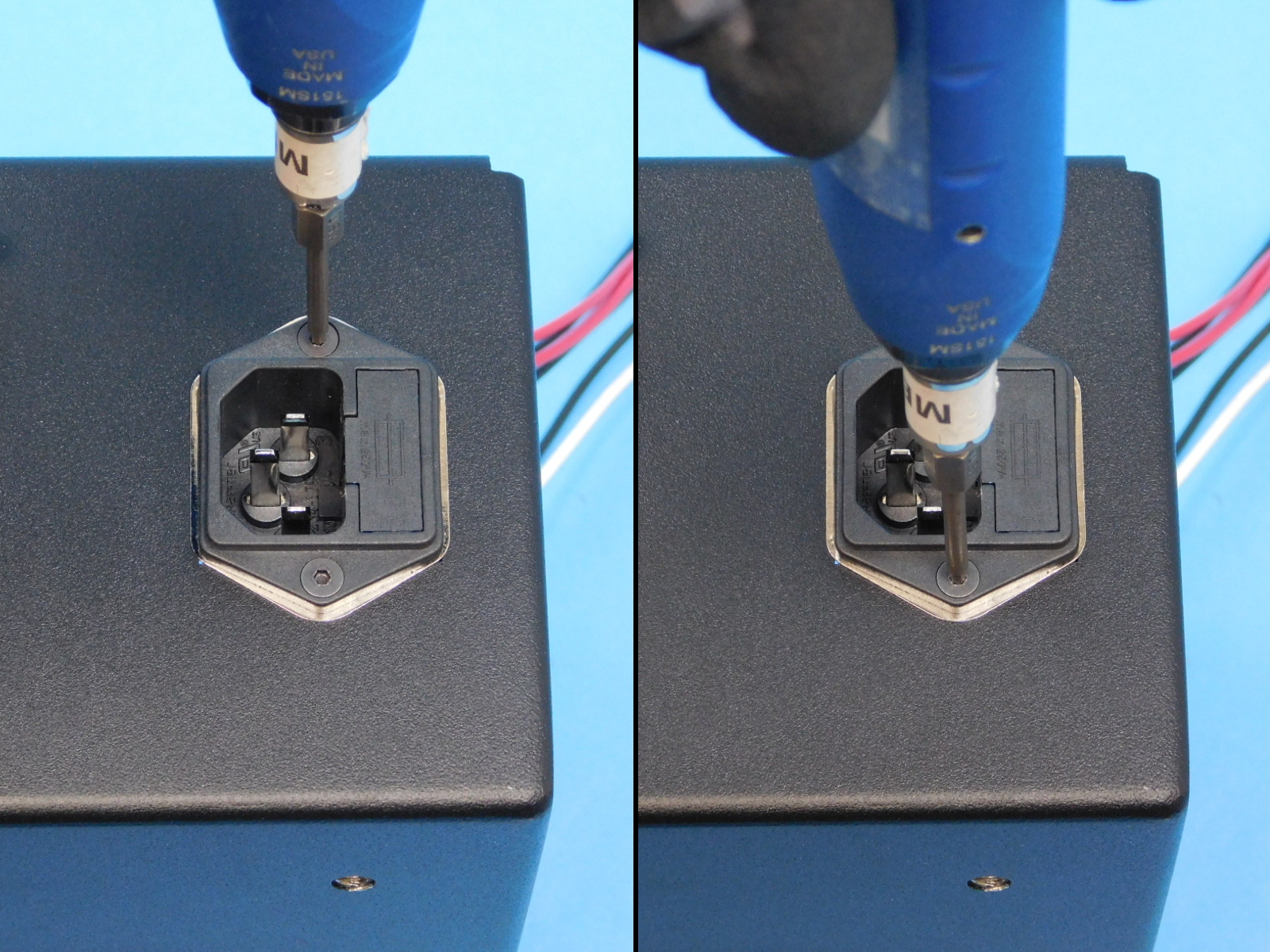
Install one receptacle [EL-MS0346] into the hole at the bottom rear of the chassis [PP-FP0149] with the plug side of the receptacle facing the top of the chassis.
Secure using two M3x10 FHCS [HD-BT0116], torque to 5in-lbs

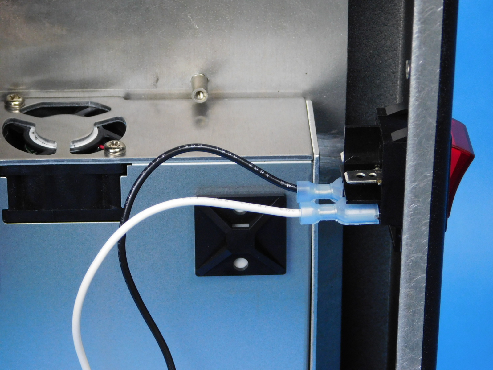
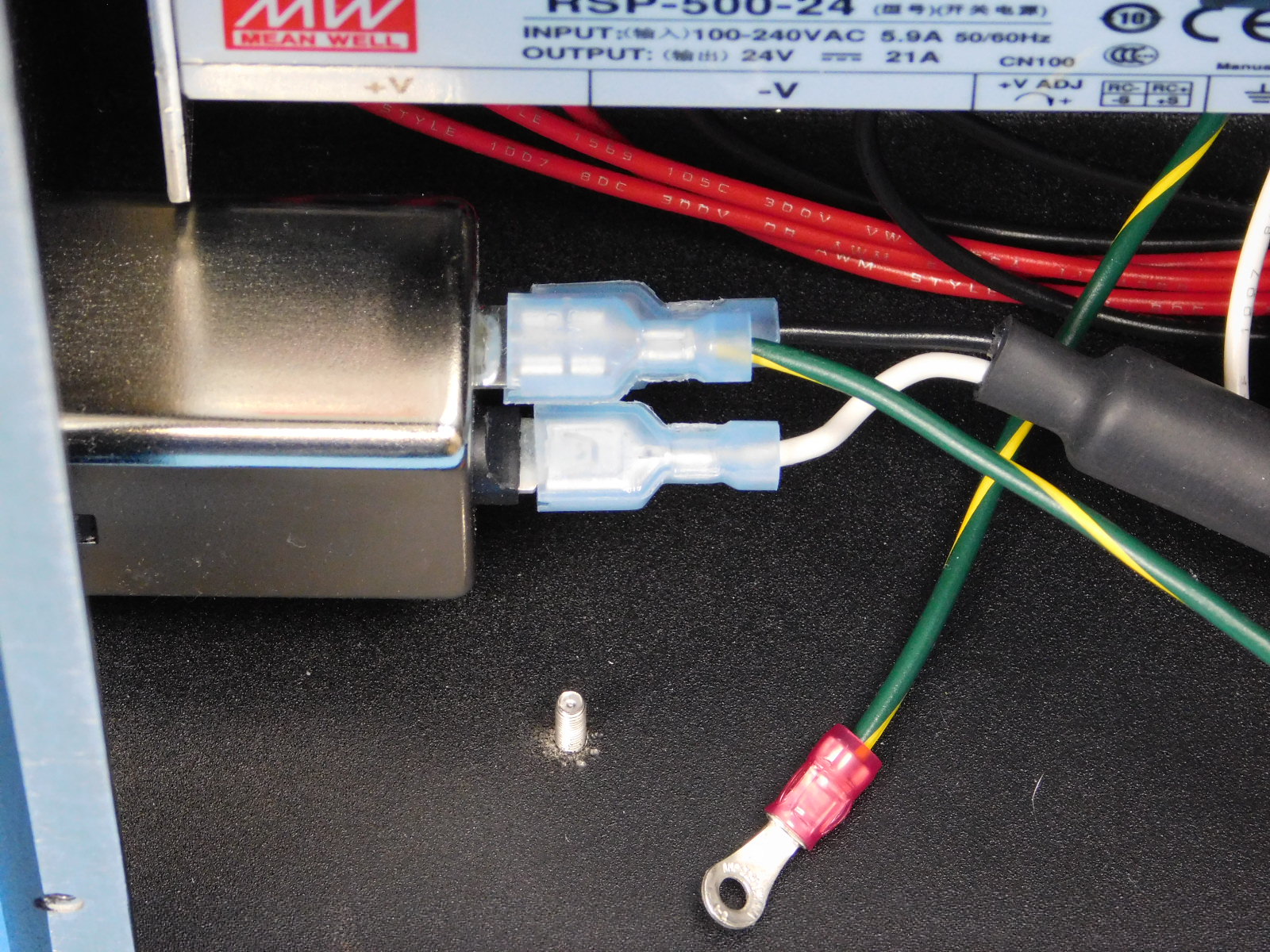
Obtain one Plug to Switch Harness [EL-HR0168]
Connect the ferrite end of the harness to the bottom two prongs of the receptacle with the black lead on the prong closest the inside of the case, and the white lead on the prong closest the outside of the case.
Connect the other end of the harness to the bottom two terminals of the switch with the black lead on the prong closest the inside of the case, and the white lead on the prong closest the outside of the case.
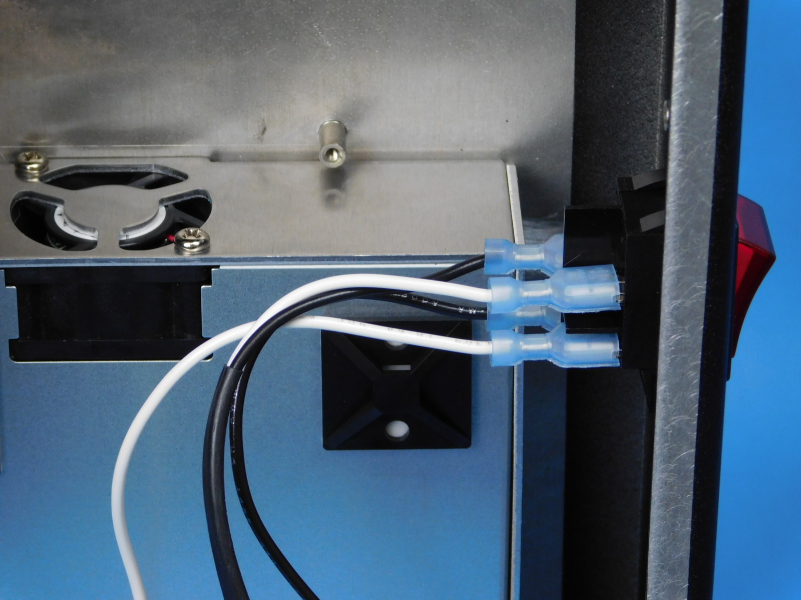
Connect the white and black leads from the power supply [EL-HR0157] to the two terminals on the top of the switch similarly; with the black lead on the prong closest the inside of the case, and the white lead on the prong closest the outside of the case.
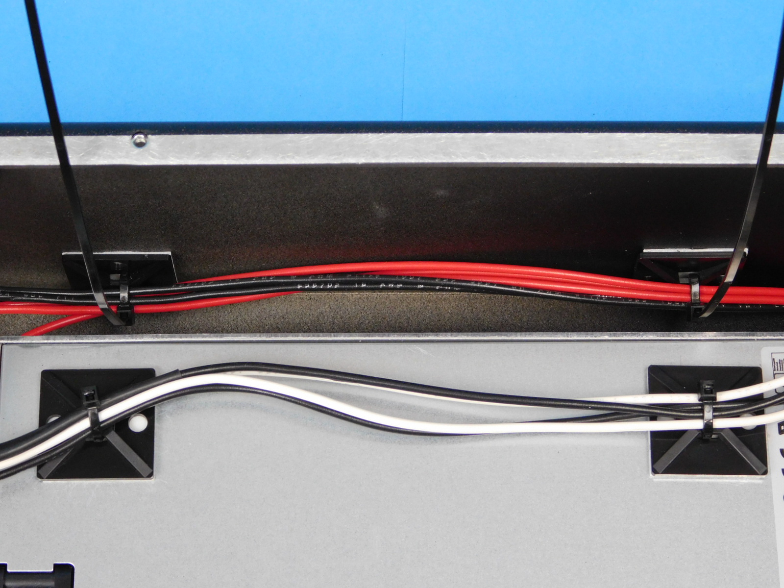
Secure the two black leads and the two white leads to the cable tie downs on the PSU using two zip ties [HD-MS0058] as pictured.
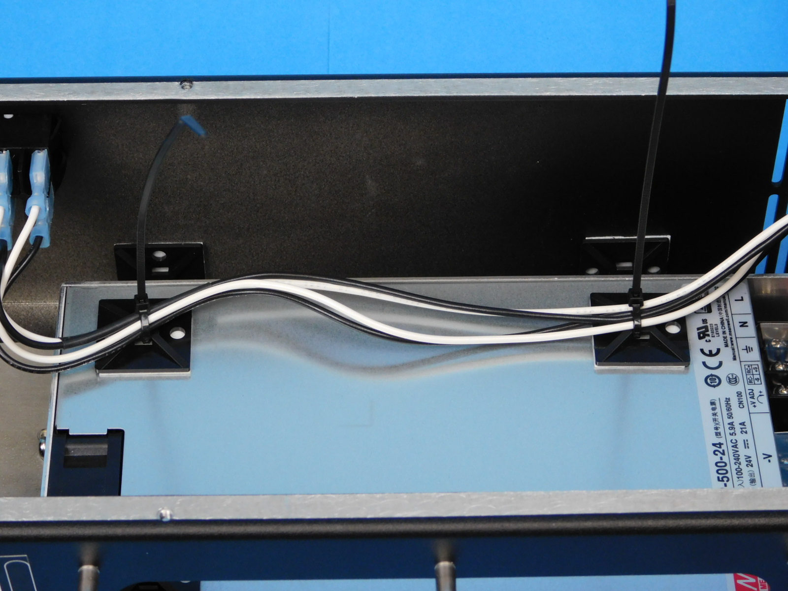
Route the CB DC Power Harness behind the black/white leads and the ground.
Secure the 2x- black/2x- white leads to the tie down on the bottom of the chassis, as pictured.
Secure the CB DC Power Harness to the front wall as pictured using two (2) zip ties [HD-MS0058]
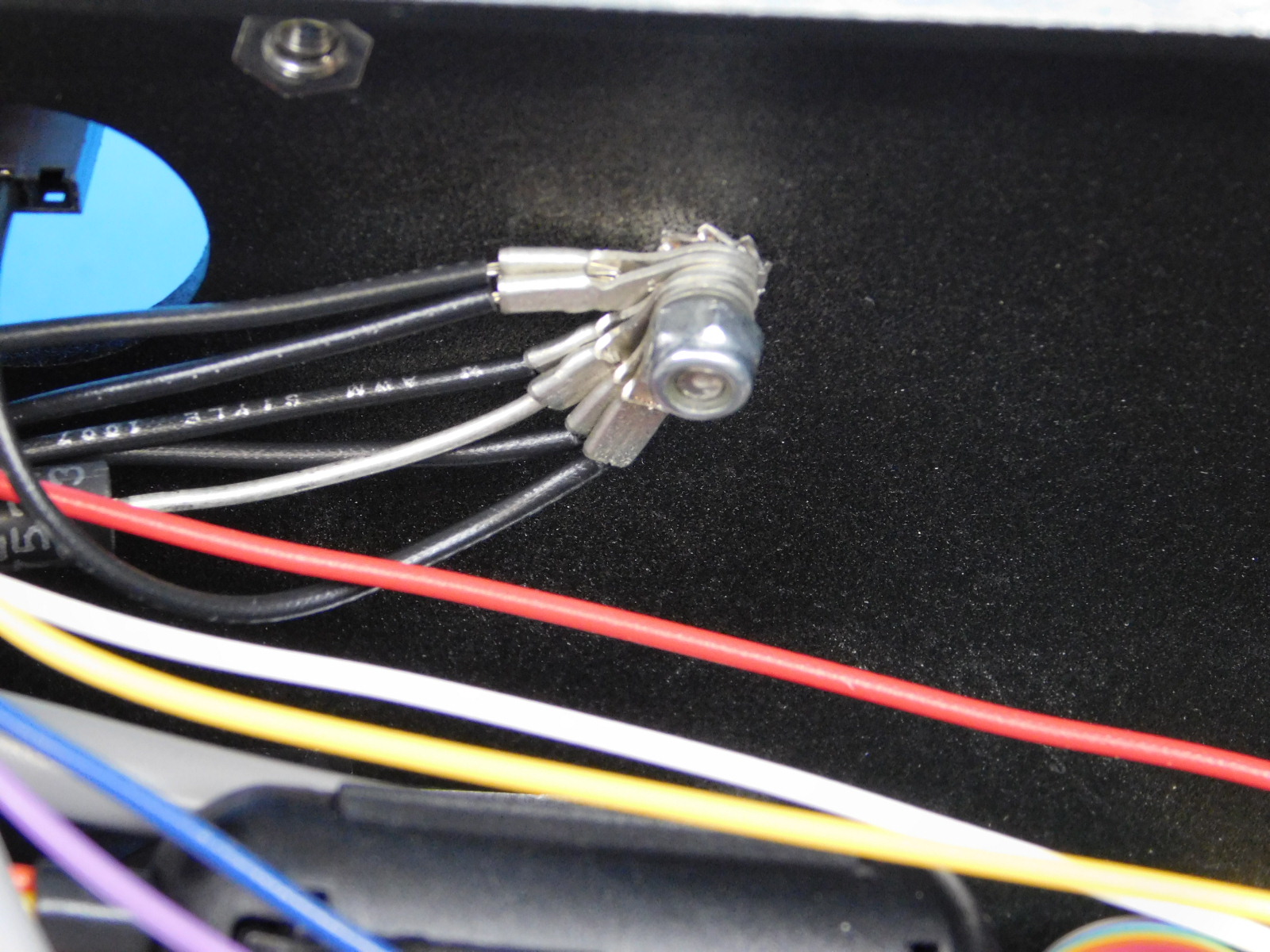
Connect the blue spade terminal of the Plug to Ground harness [EL-HR0167] to the top terminal on the receptacle.

Before handling any PCB or LCD assemblies, ensure you are properly grounded and that all handling of PCB or LCD assemblies is protected:
a) Use of ESD wrist straps is required any time a PCB or LCD is handled outside of a silver ESD protective bag, including but not limited to when they are installed inside assemblies. Ensure the inner metal button of the wrist strap is contacting your skin.
b) All work should be performed upon an ESD work mat
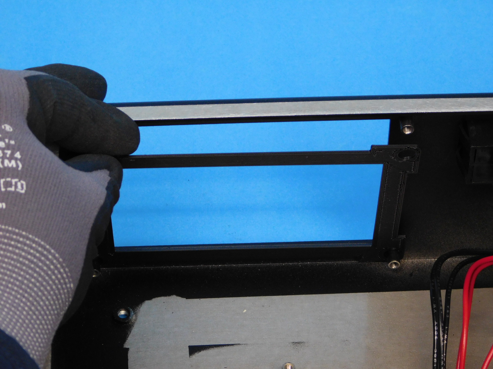
First place the LCD Bezel [PP-GP0384] inside the Electronics Chassis [PP-FP0149] with the beveled side facing out
Obtain one tested LCD Assembly [AS-PR0118]
Carefully remove the LCD Assembly from the static bag
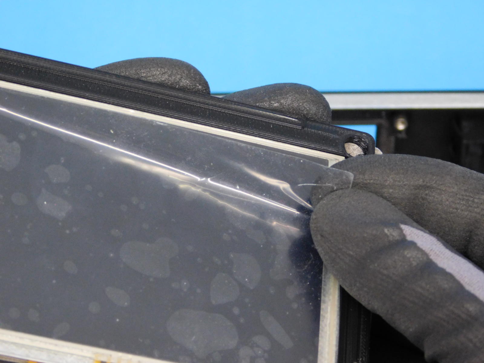
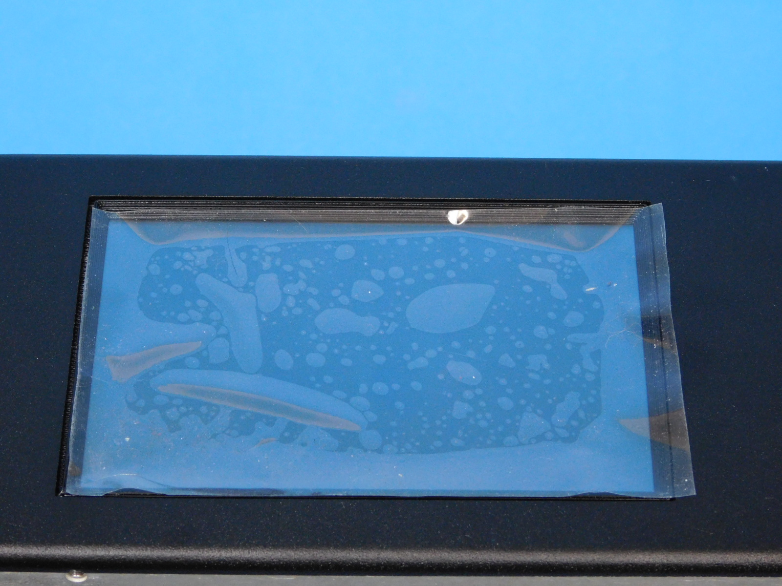
Carefully remove the clear protective cover from the LCD touchscreen, this cannot be removed after installation. Set it aside on a clean surface, it clings well to the side of the workstation monitors. This will be reapplied after the assembly is installed into the chassis to protect the screen in transit between work areas.
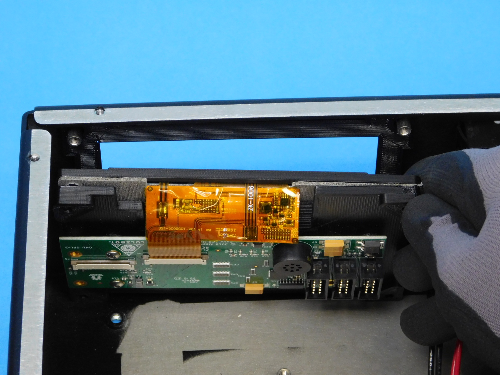
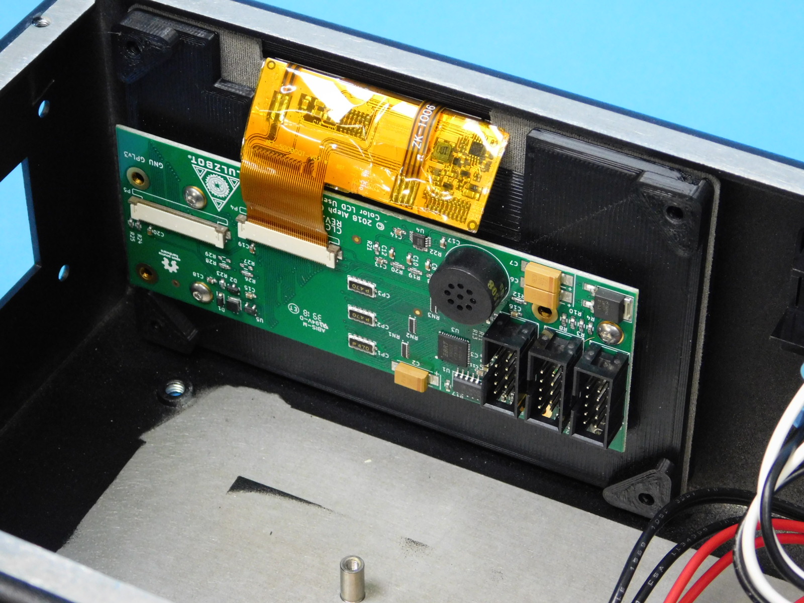
When placing the LCD into the chassis, the ten pin connector headers on the LCD board should be towards the bottom of the chassis.
Place the LCD assembly into the chassis by carefully aligning the holes with the posts inside the chassis.
Ensure the LCD pad is fitted proper around the outside of all four posts.
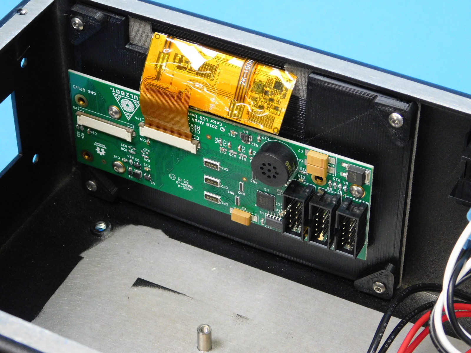
Secure the LCD assembly using four (4) M3x8 Stainless BHCS [HD-BT0104]
Carefully place the previously removed protective cover over the LCD touchscreen, it will cover the bezel as well.
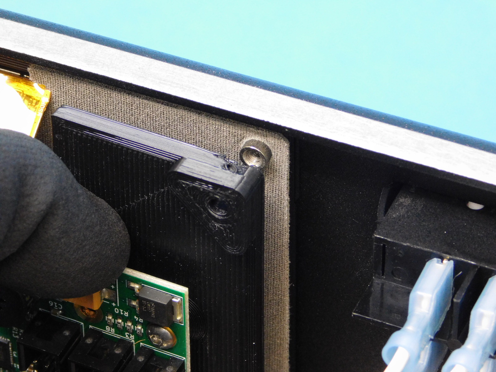
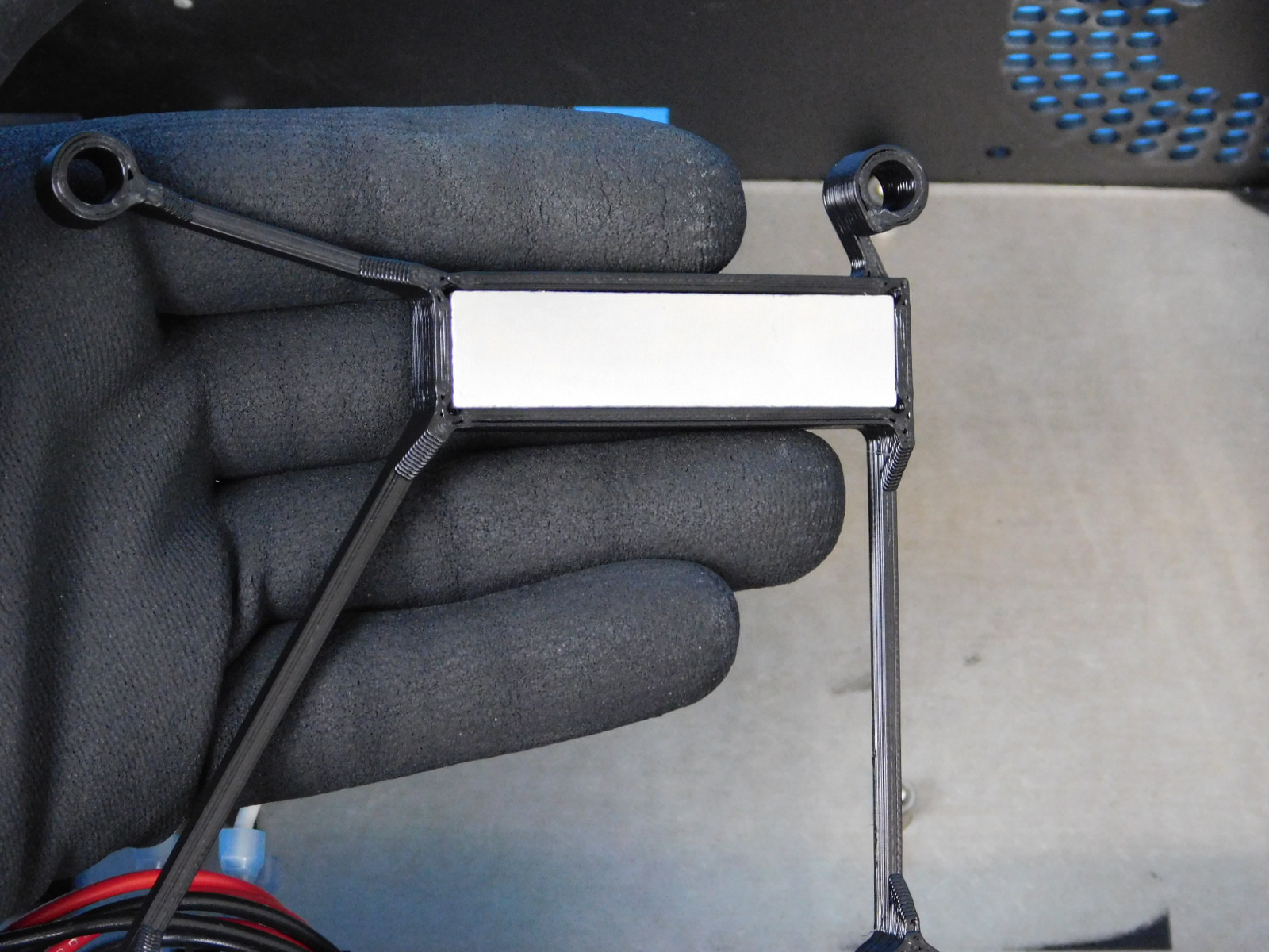
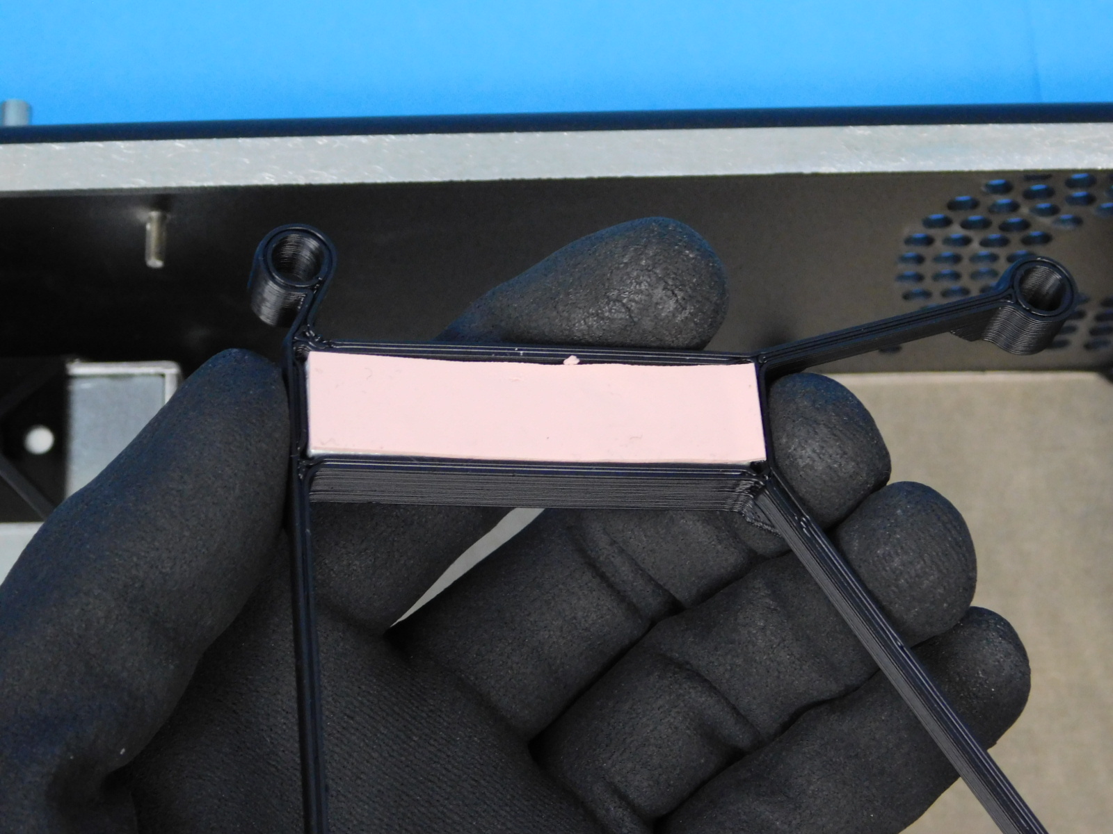
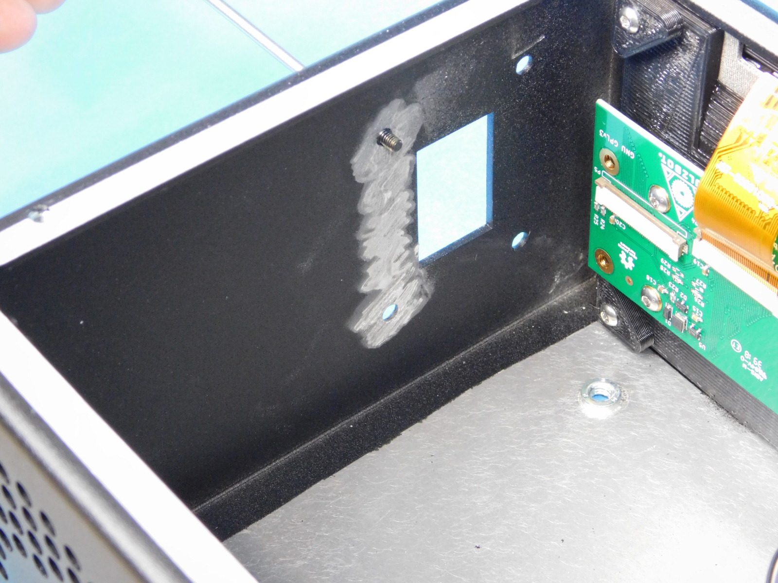
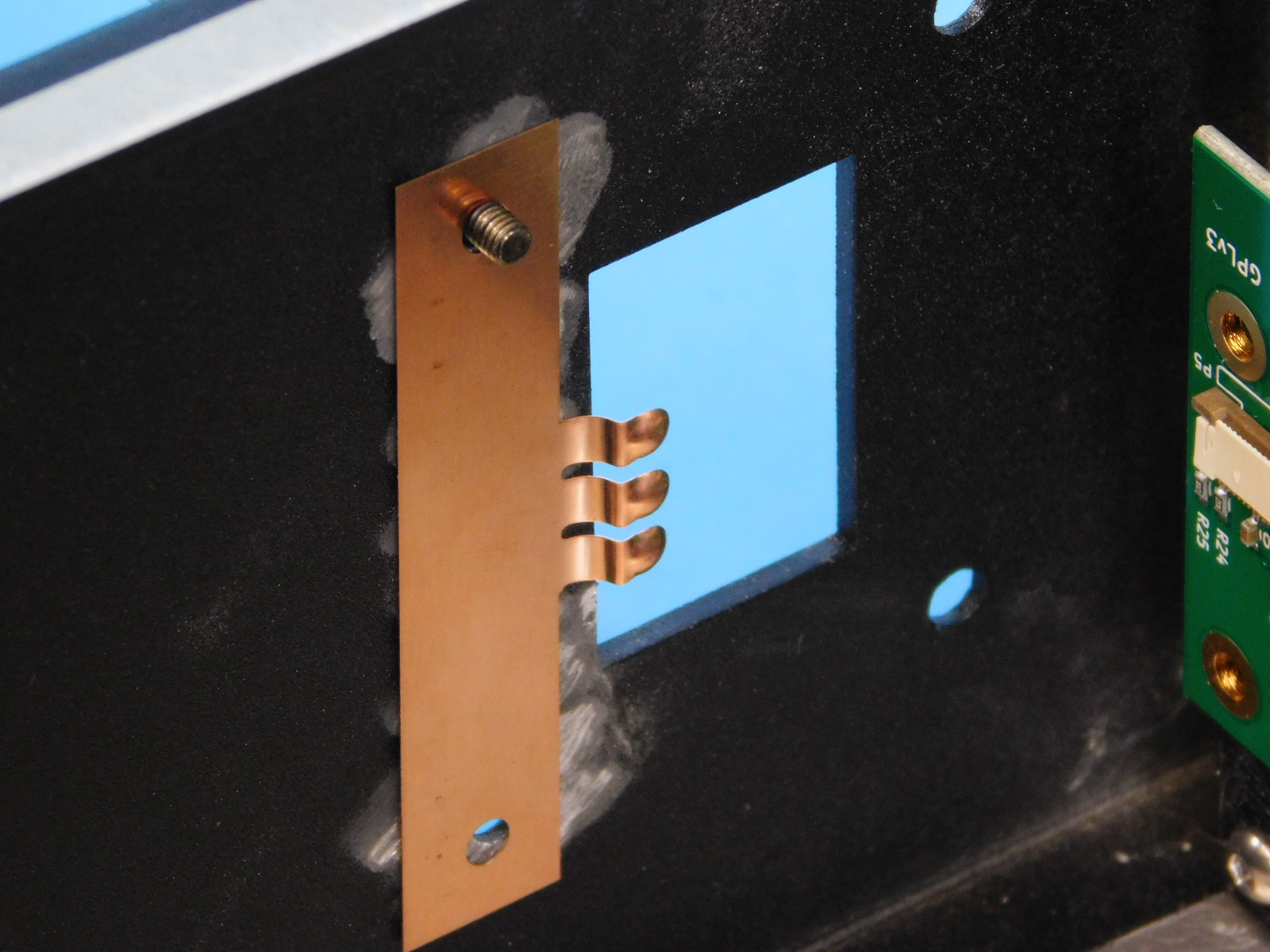
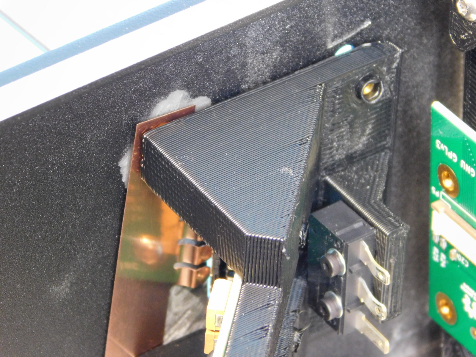
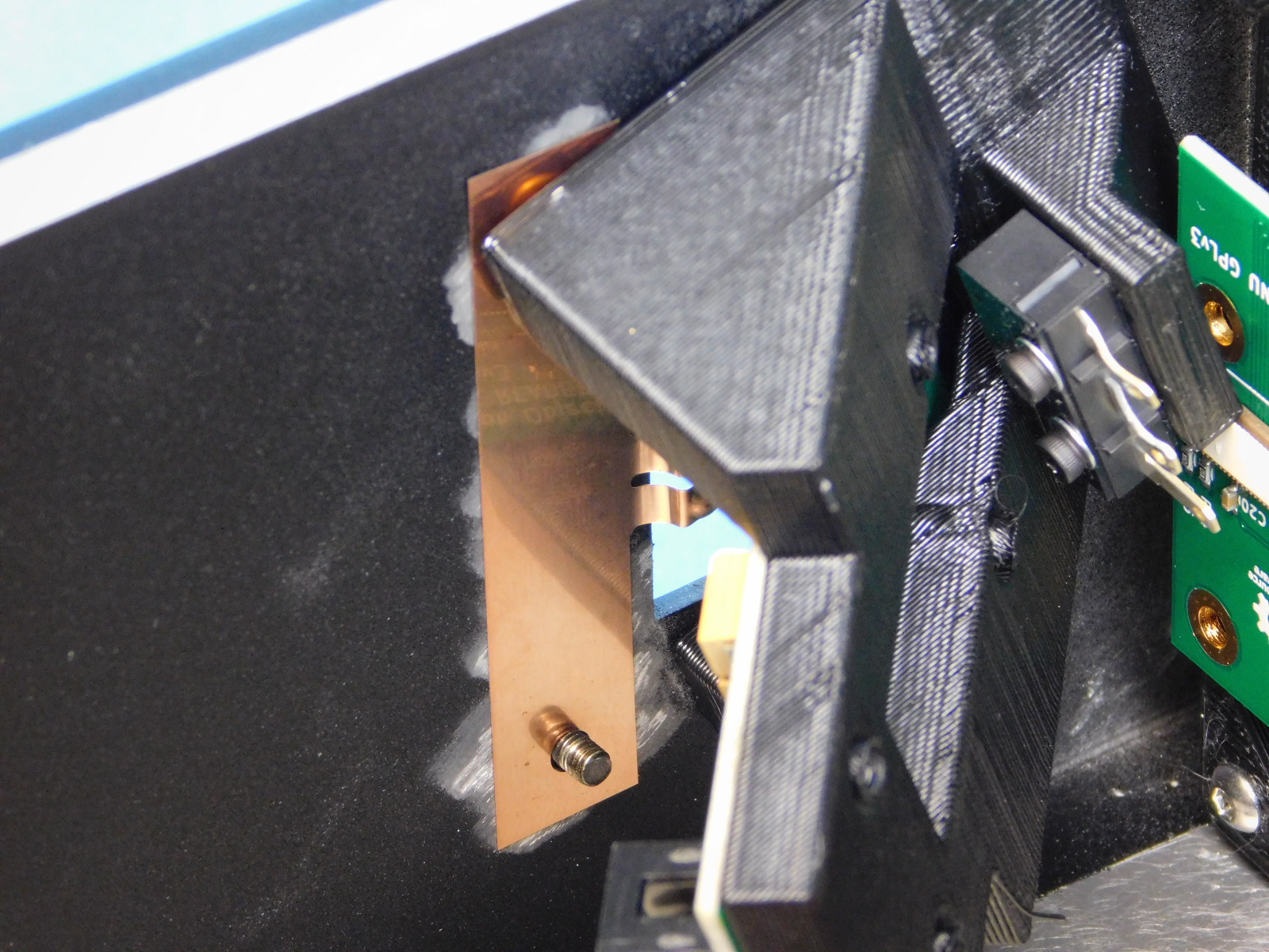
Fit one heat sink [PP-MP0234] inside of a heat sink frame [PP-GP0389]
Cover each exposed side of the heat sink with one strip of Thermal Gap Filler [HD-MS0463]
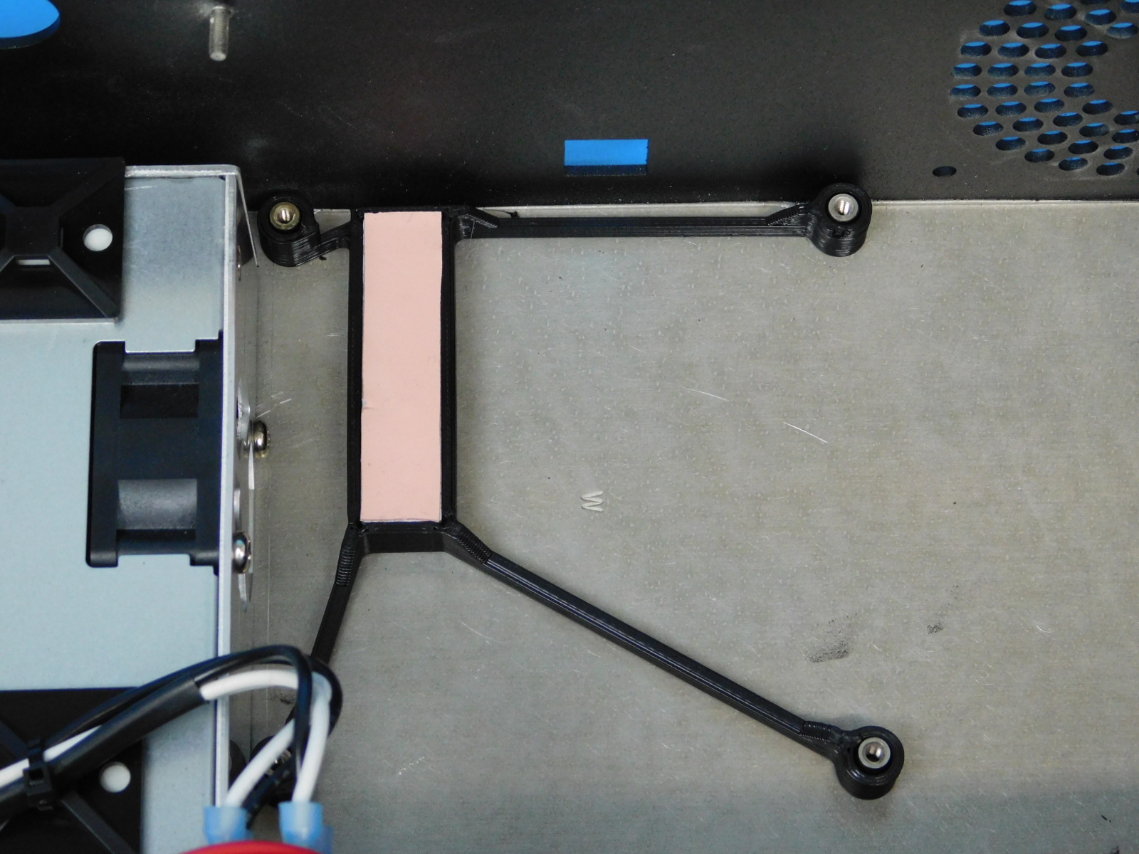
Place the heat sink inside the chassis, oriented as pictured.
See step 8 for ESD protection measures
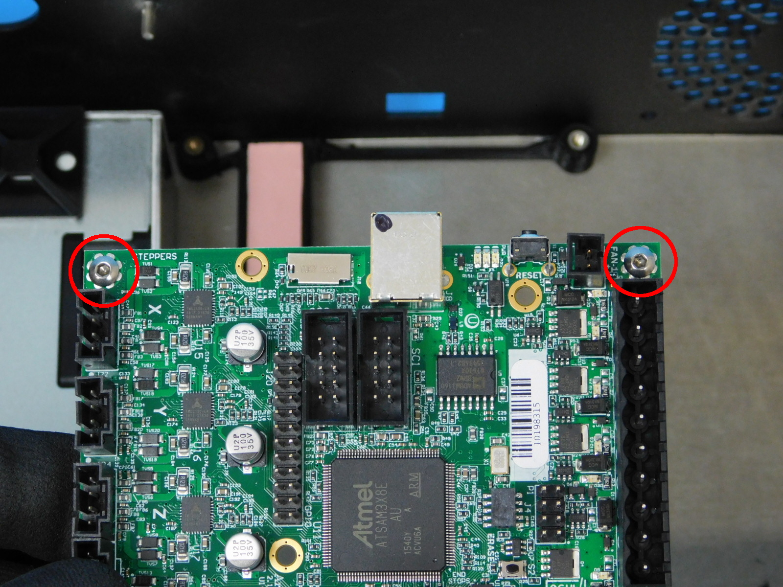
Obtain one Archim PCBA [PC-BD0113]
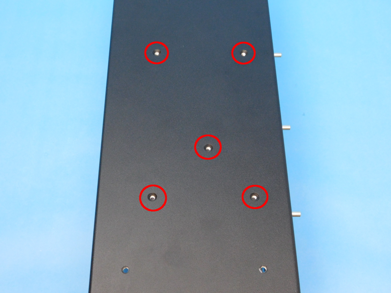
Place one M3x8 Stainless BHCS [HD-BT0104] in the two highlighted holes. Lower the PCBA into the chassis as pictured. Install one more M3x8 Stainless BHCS [HD-BT0104] into the location shown. Tighten all three screws securely.
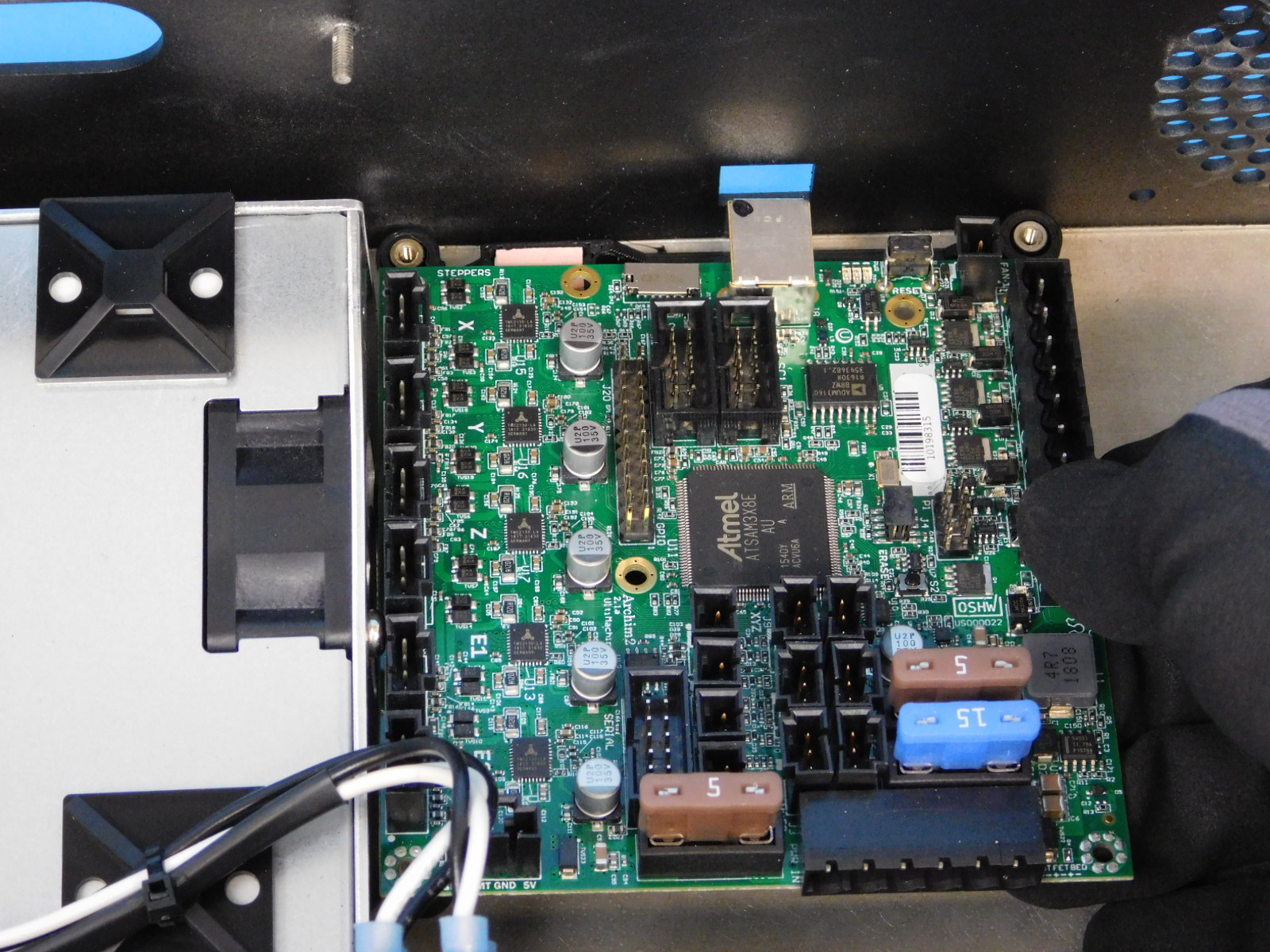
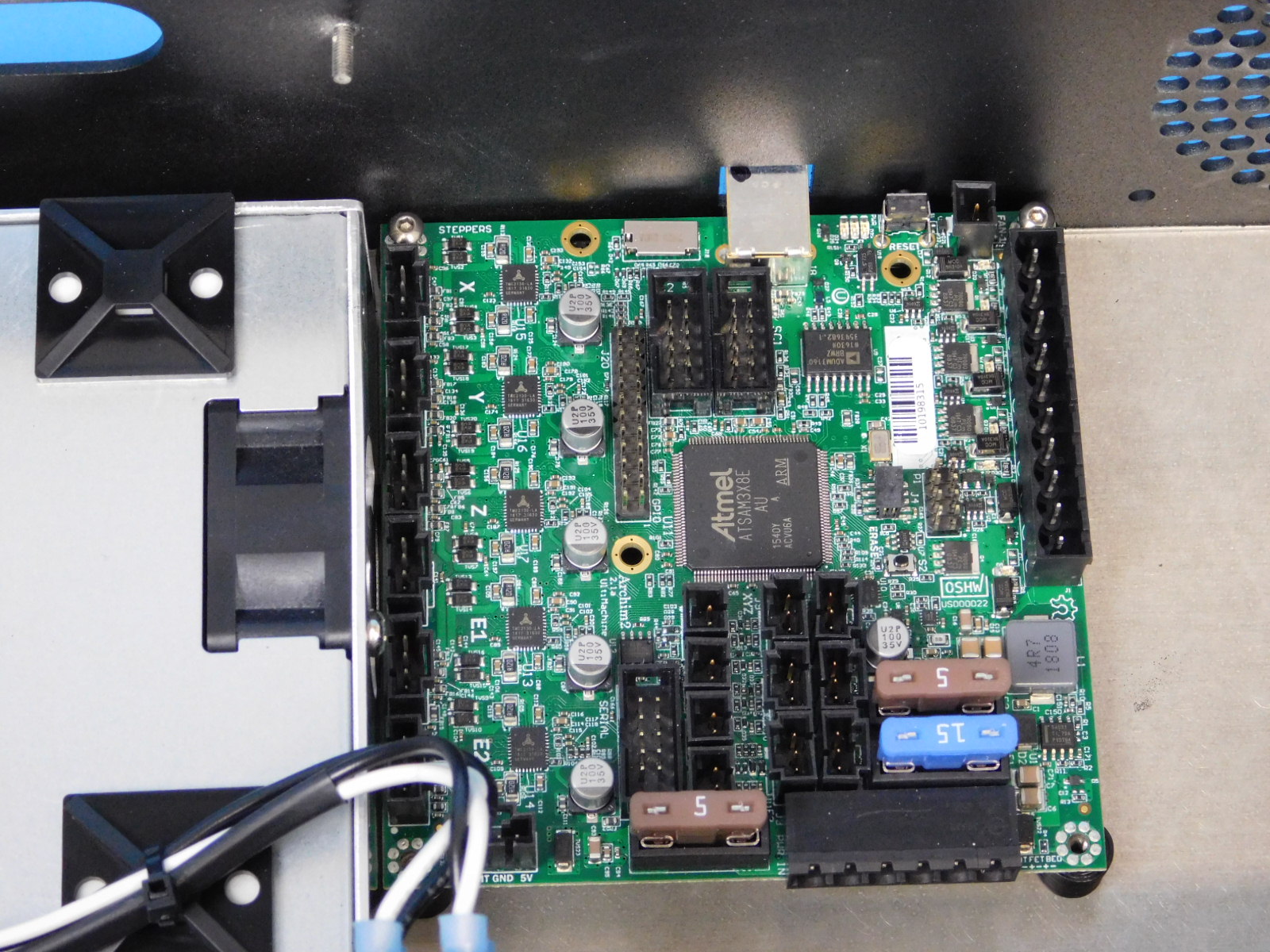
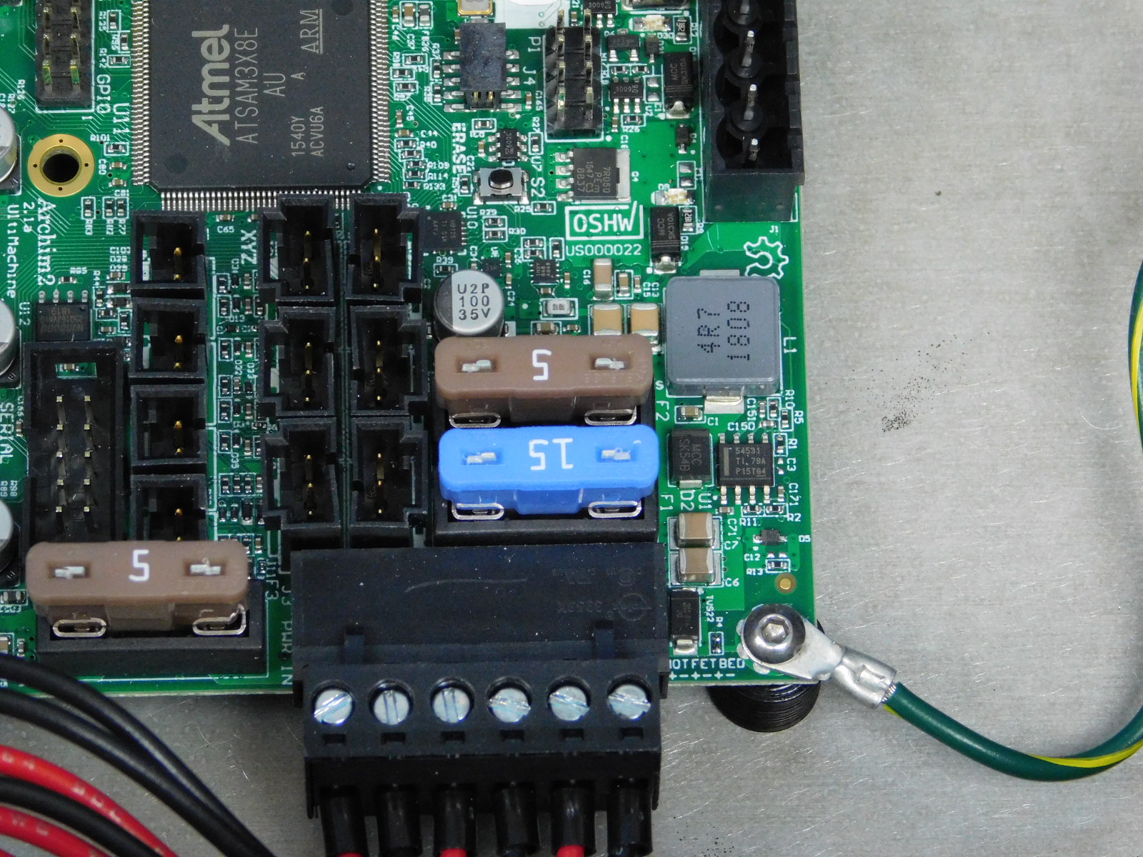
Connect the CB DC Power Harness to the Archim as pictured.
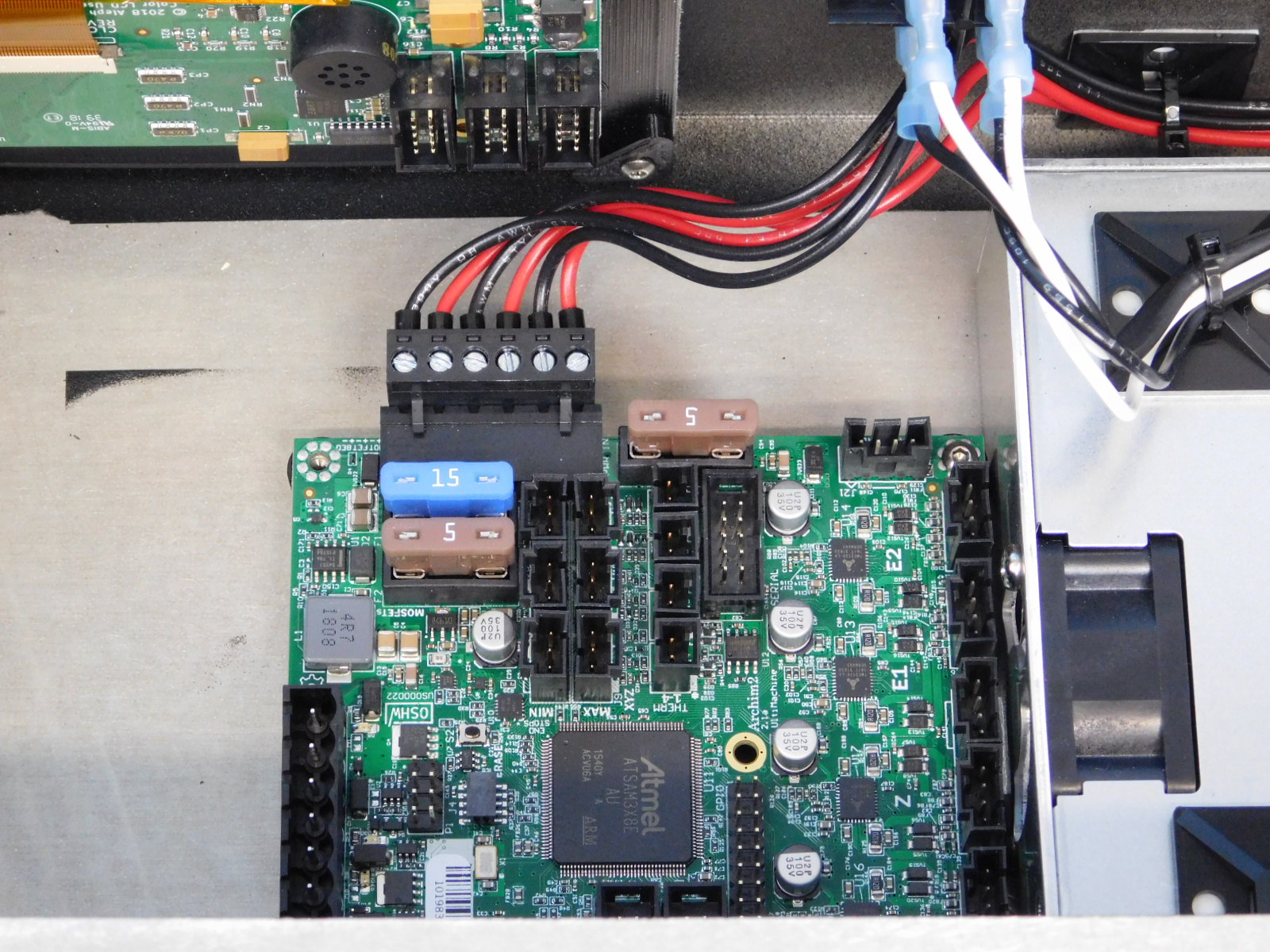
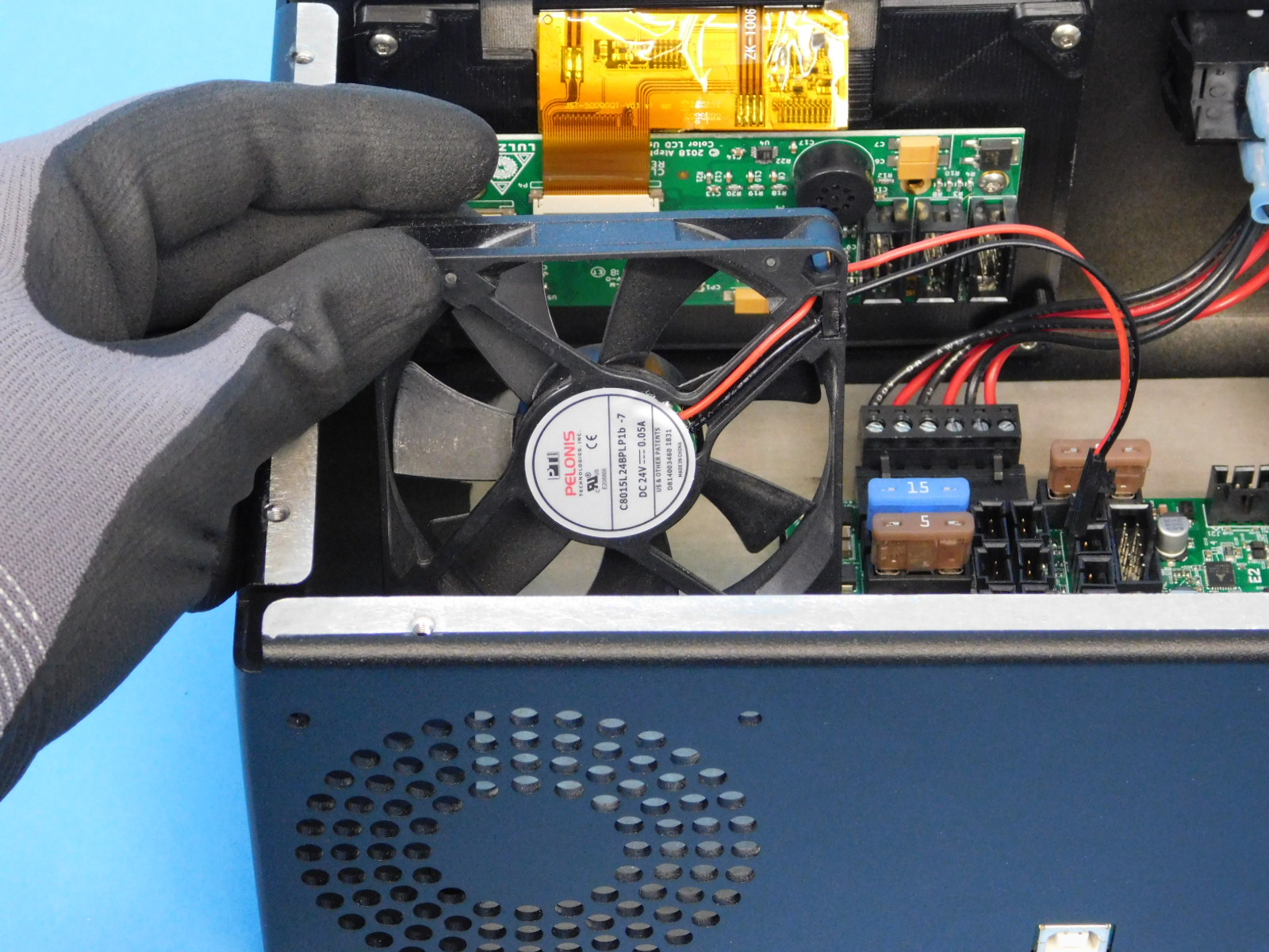
Obtain one CB Case Fan [EL-FA0061]
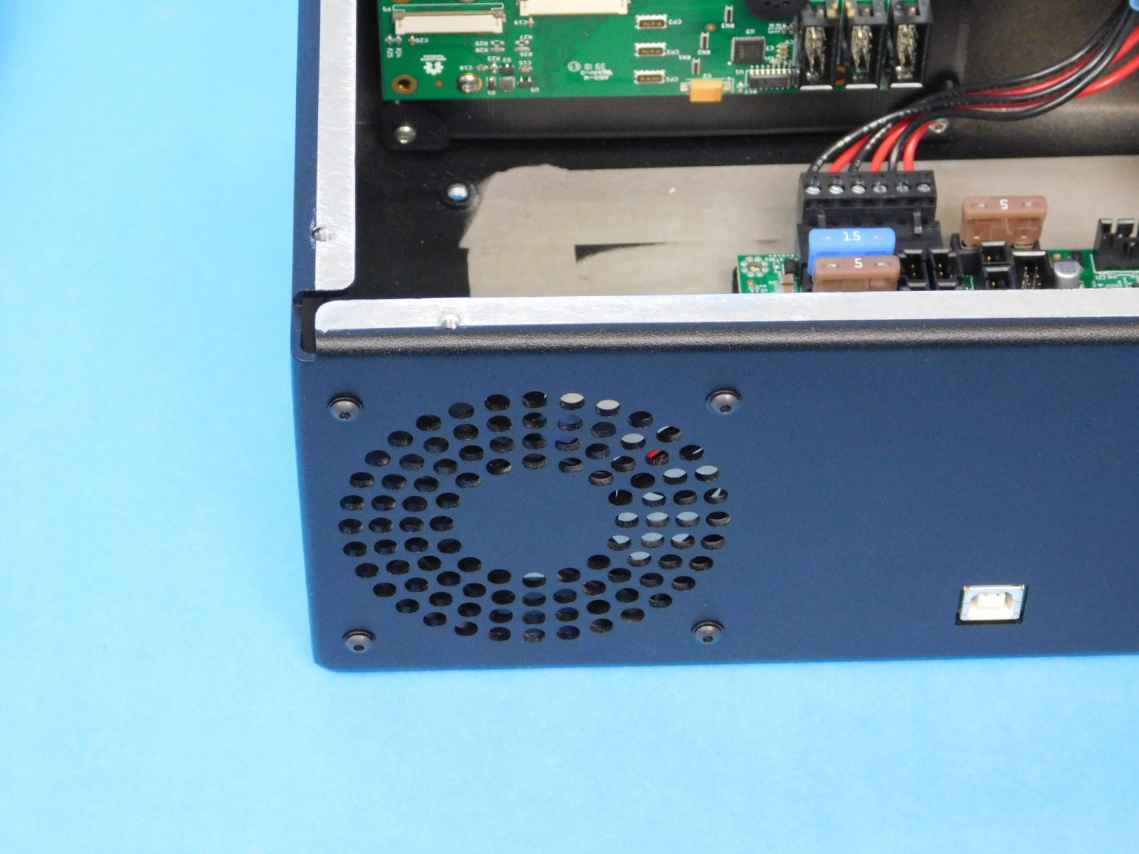
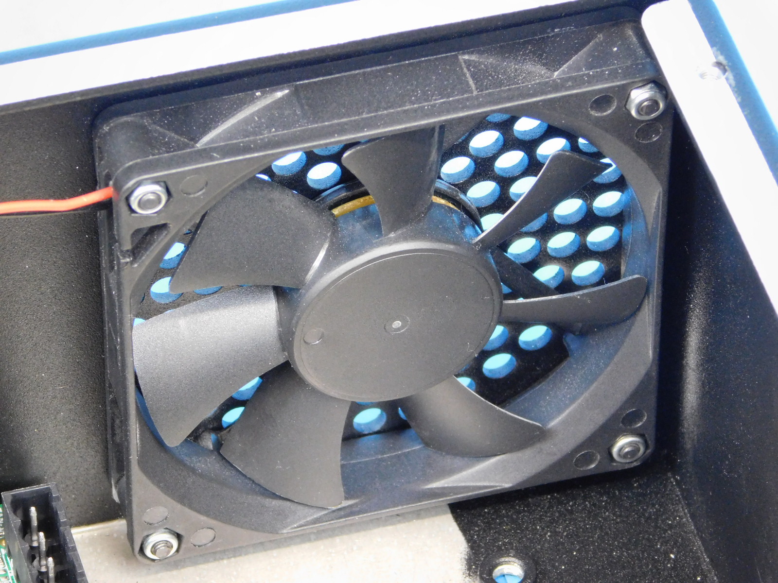
Place the fan into the chassis in the location and orientation shown.
Secure using four (4) M3x20 BHCS [HD-BT0171] with washers [HD-WA0038] and four (4) M3 Nyloc Nuts [HD-NT0001].
Connect the Case Fan to the 2 pin connector at the top left of the Archim, as pictured.

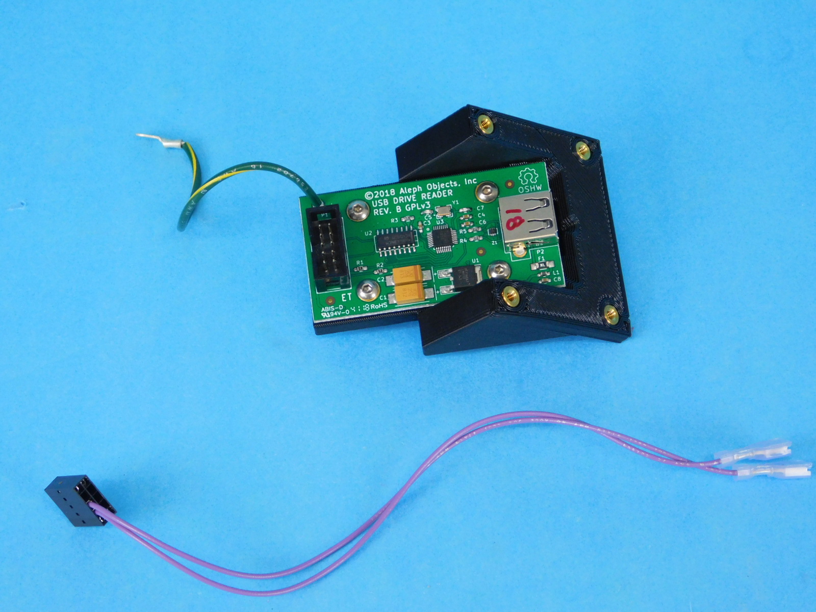
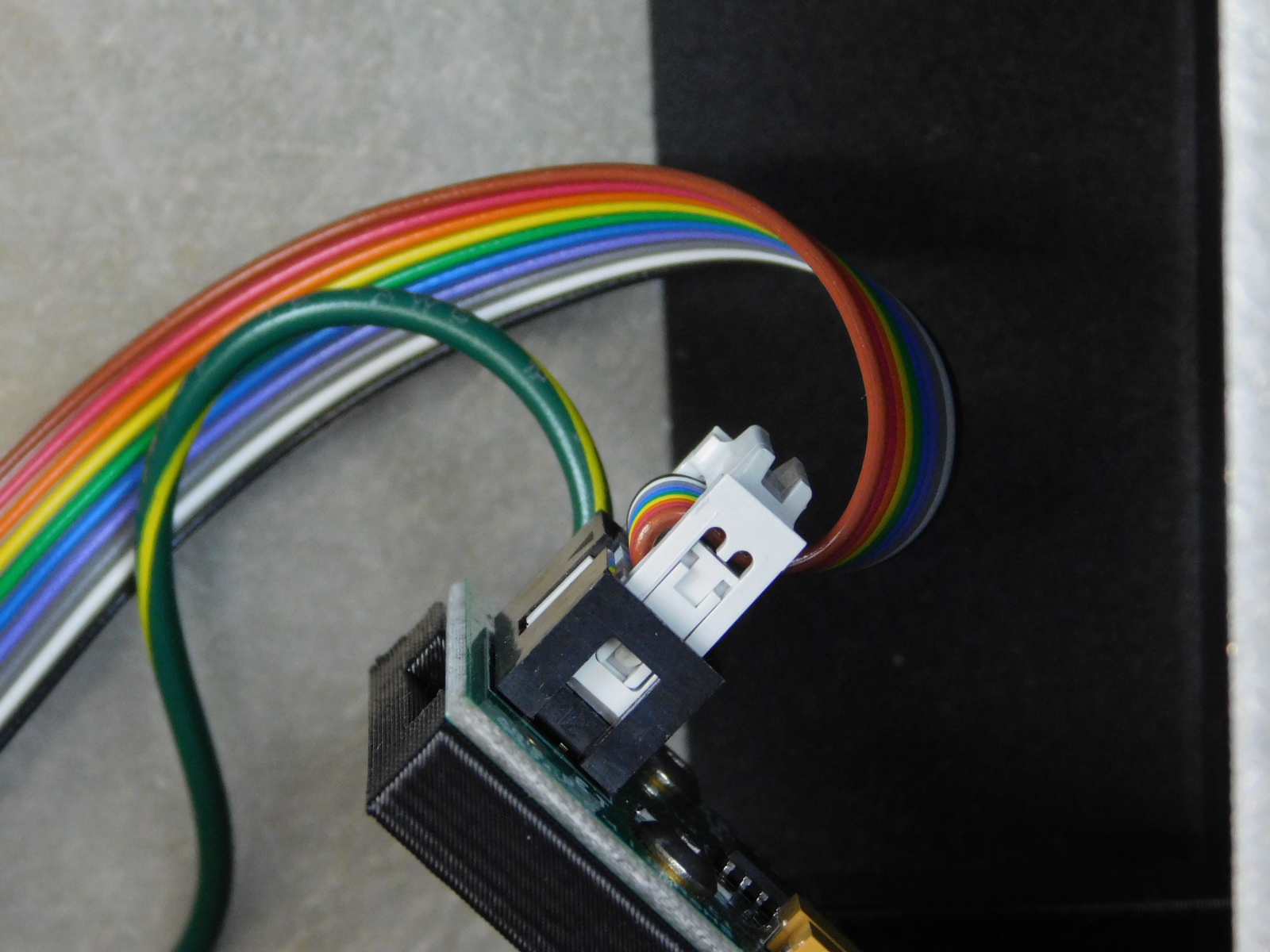
Obtain one USB Reader Assembly [AS-PR0119] and one Eraser switch harness [EL-HR0156]
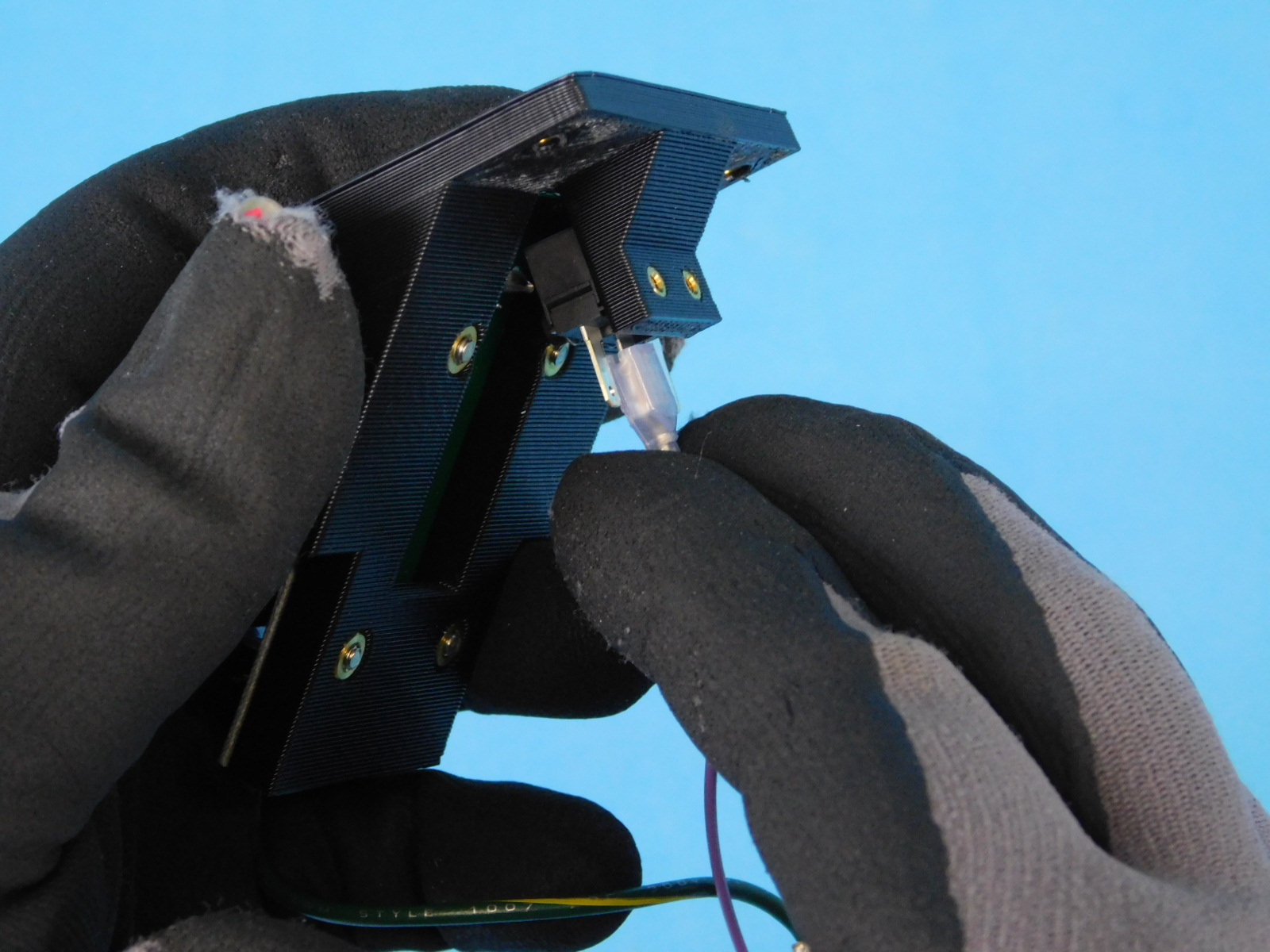
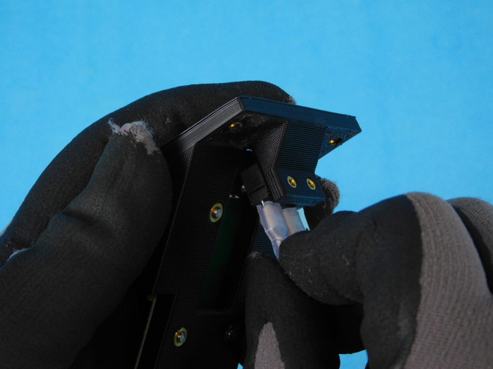
Attach the eraser switch harness to the USB reader as shown.
See orientation photo
Place one M3x6 FHCS [HD-BT0128] through the hole shown
Place the USB static fingers [EL-MS0535] on the fastener as shown; orientation is key.
Begin threading the fastener into the insert in the top of the USB reader assembly as shown
Pivot the USB reader assembly and place another M3x6 FHCS [HD-BT0128] through the lower rear hole on top of the chassis and through the hole in the USB static fingers
Pivot the USB reader assembly back into position and thread the fastener into the insert in the printed part.
Install the remaining two (2) M3x6 FHCS [HD-BT0128] and torque all four fasteners to 5in*lbs
Connect the USB Reader’s ground lead to the remaining Archim mount hole using one (1) M3x8 Stainless BHCS [HD-BT0104], tighten securely.
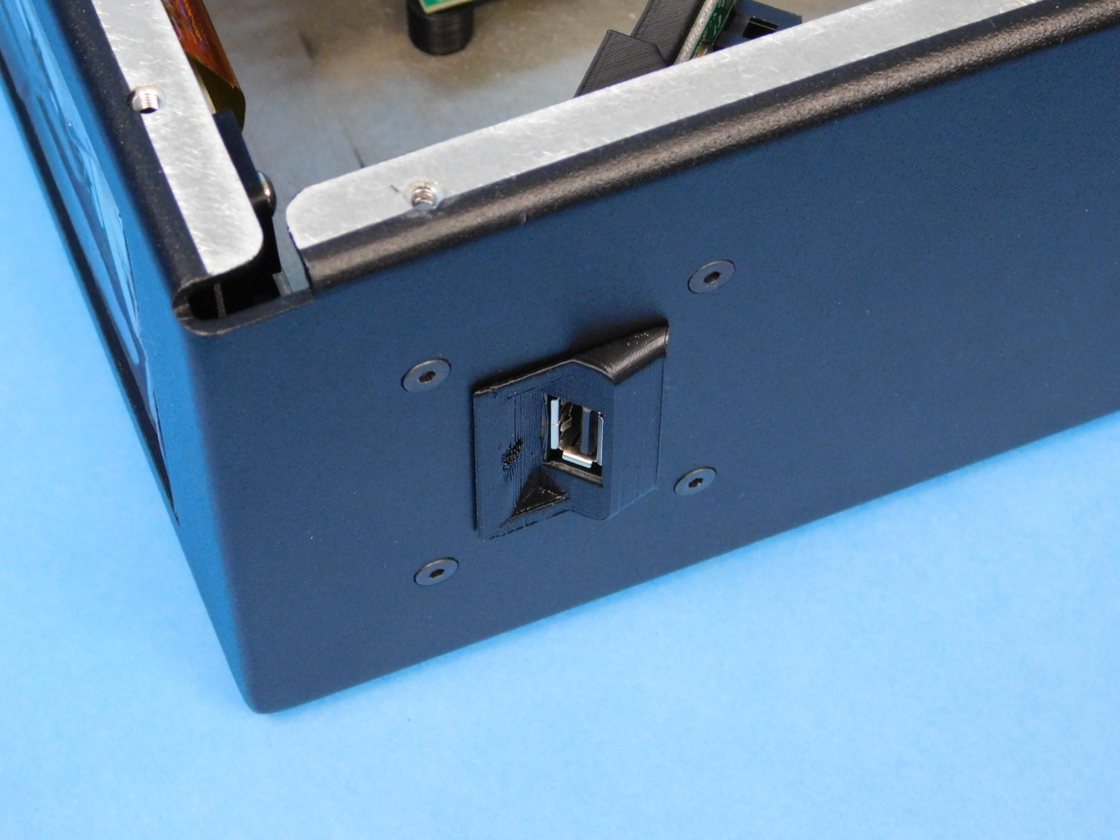
Press the USB Bezel into the case from the outside as pictured.
Ensure that it sits flush with the case.


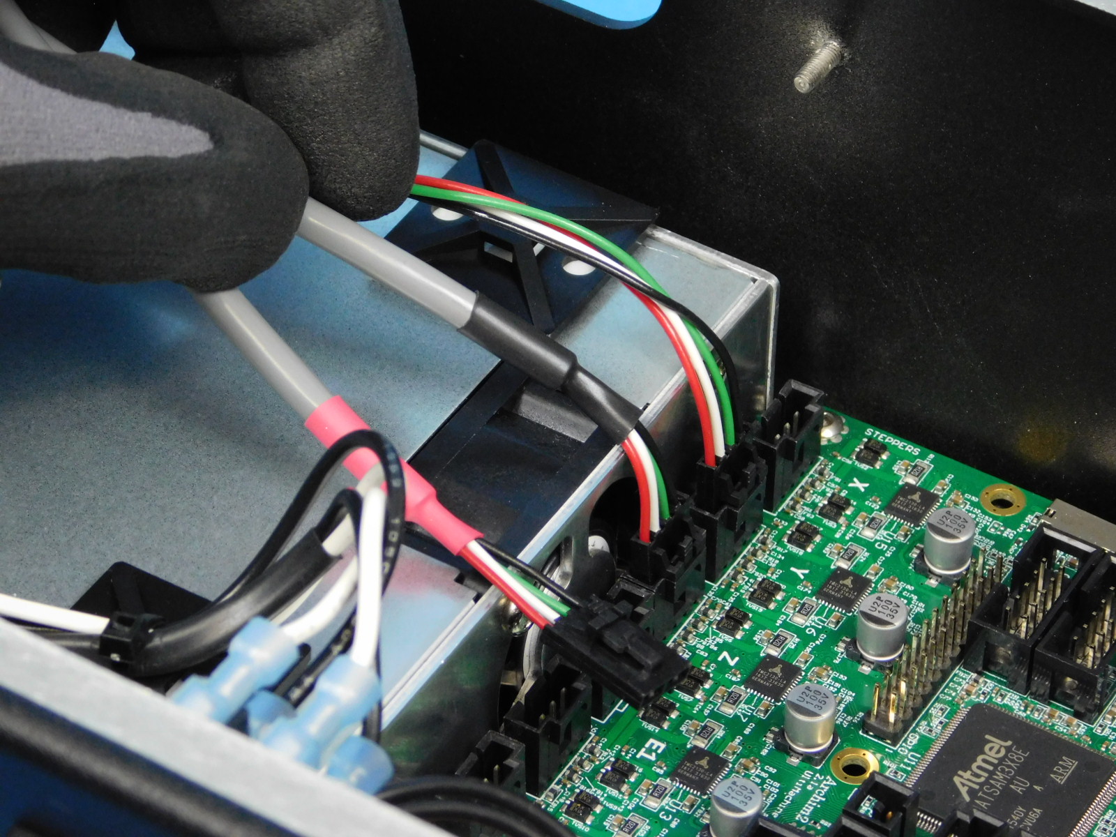
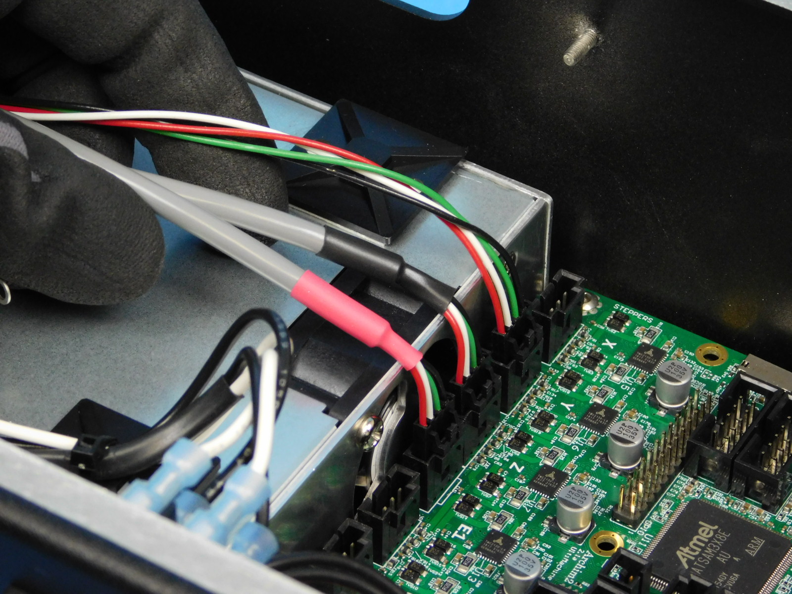
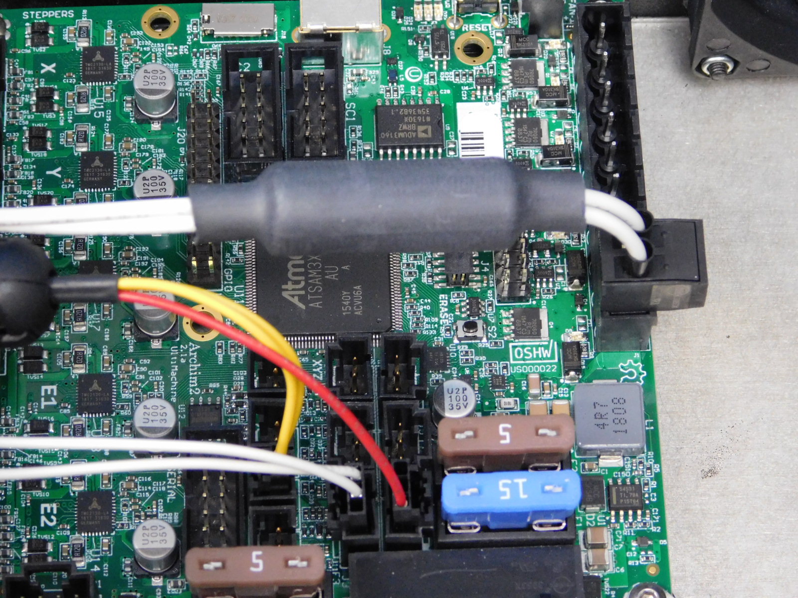
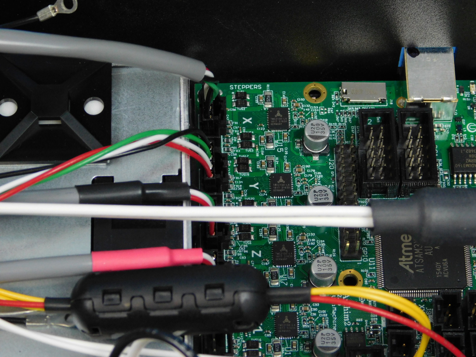
Obtain one CB YZ Harness [EL-HR0183]
Begin by connecting the Y-Motor lead, this lead is the one without colored heat shrink. See pin out diagram.
Connect the Z Motors, lead with black heat shrink on left, lead with red heat shrink on right.
Verify locations by referencing the pin out diagram.
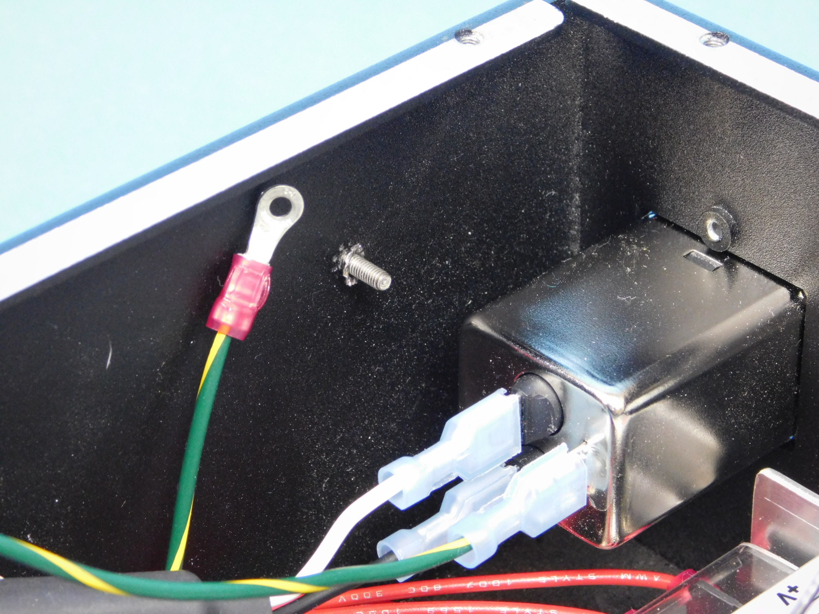
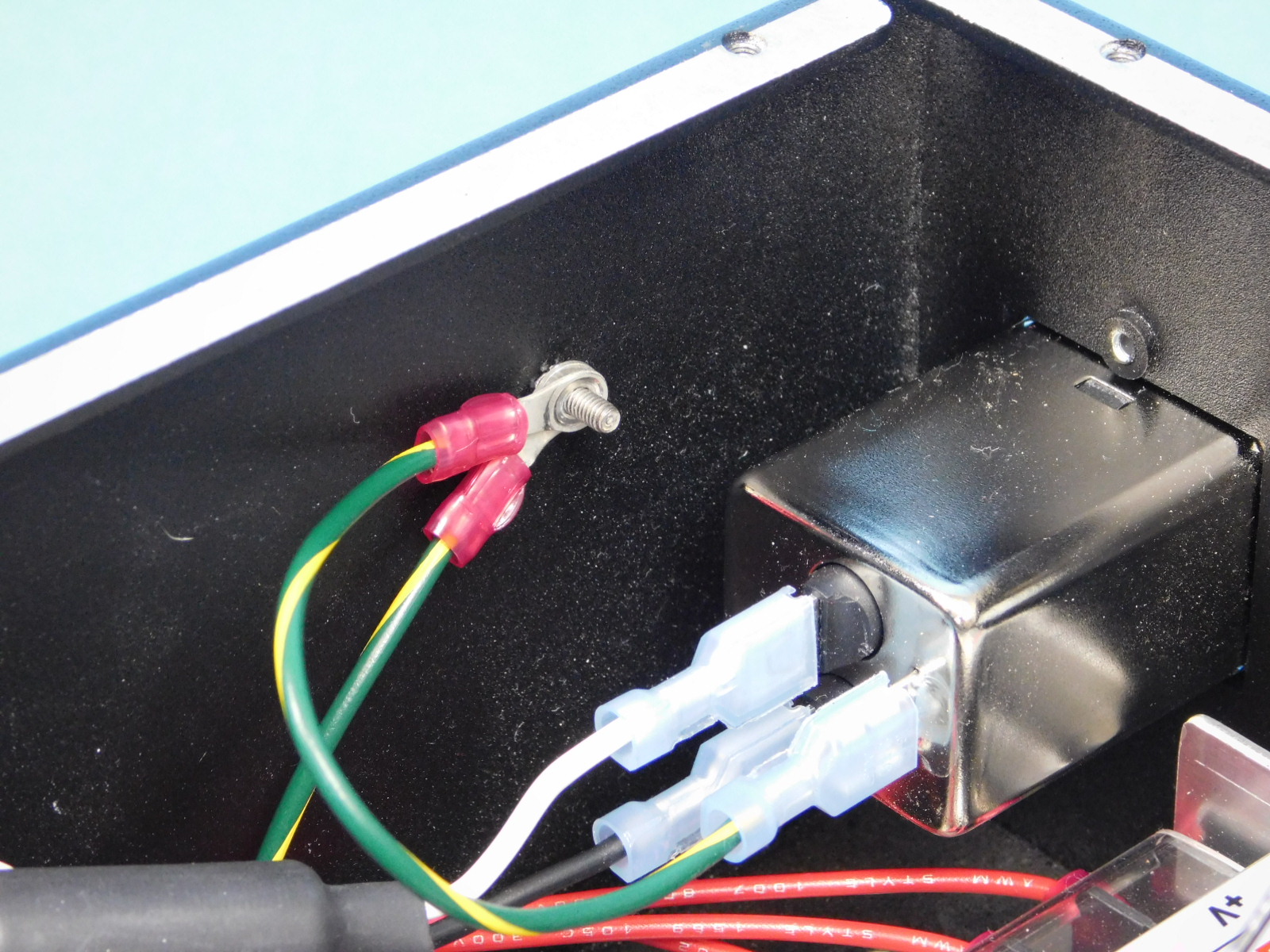
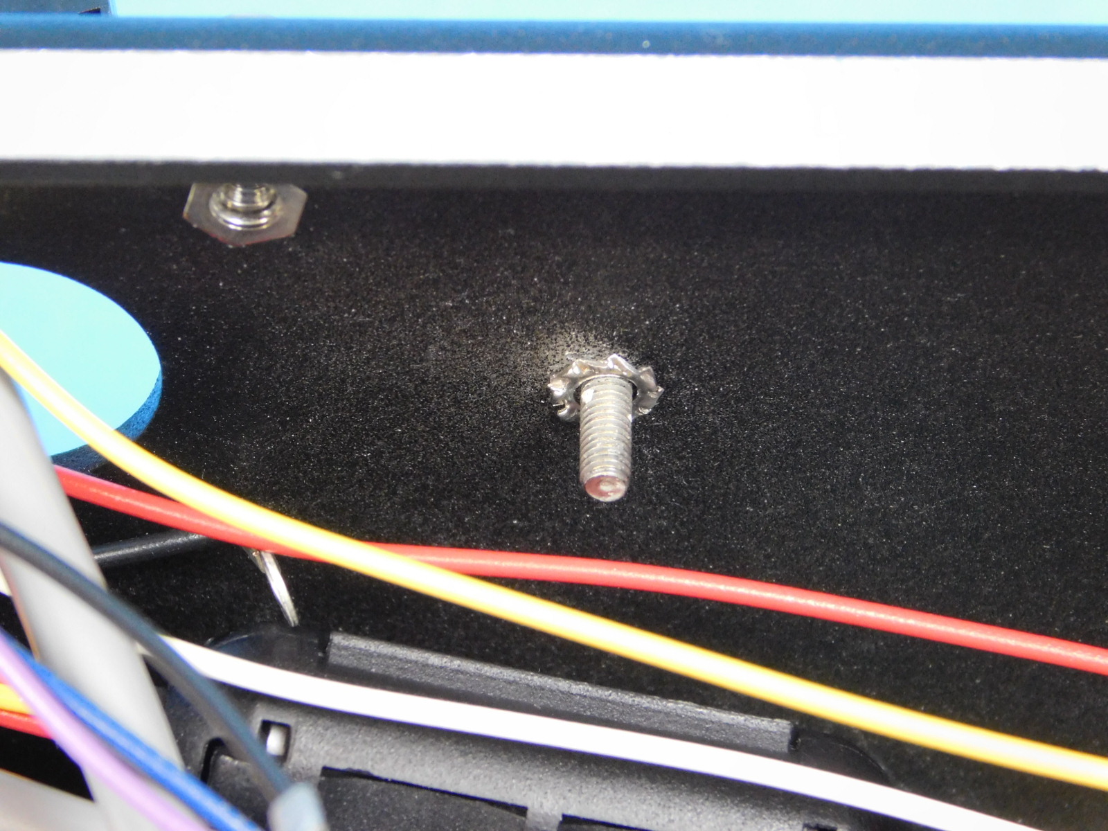
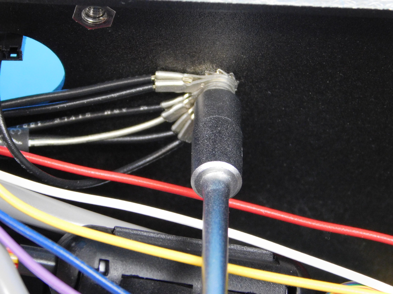
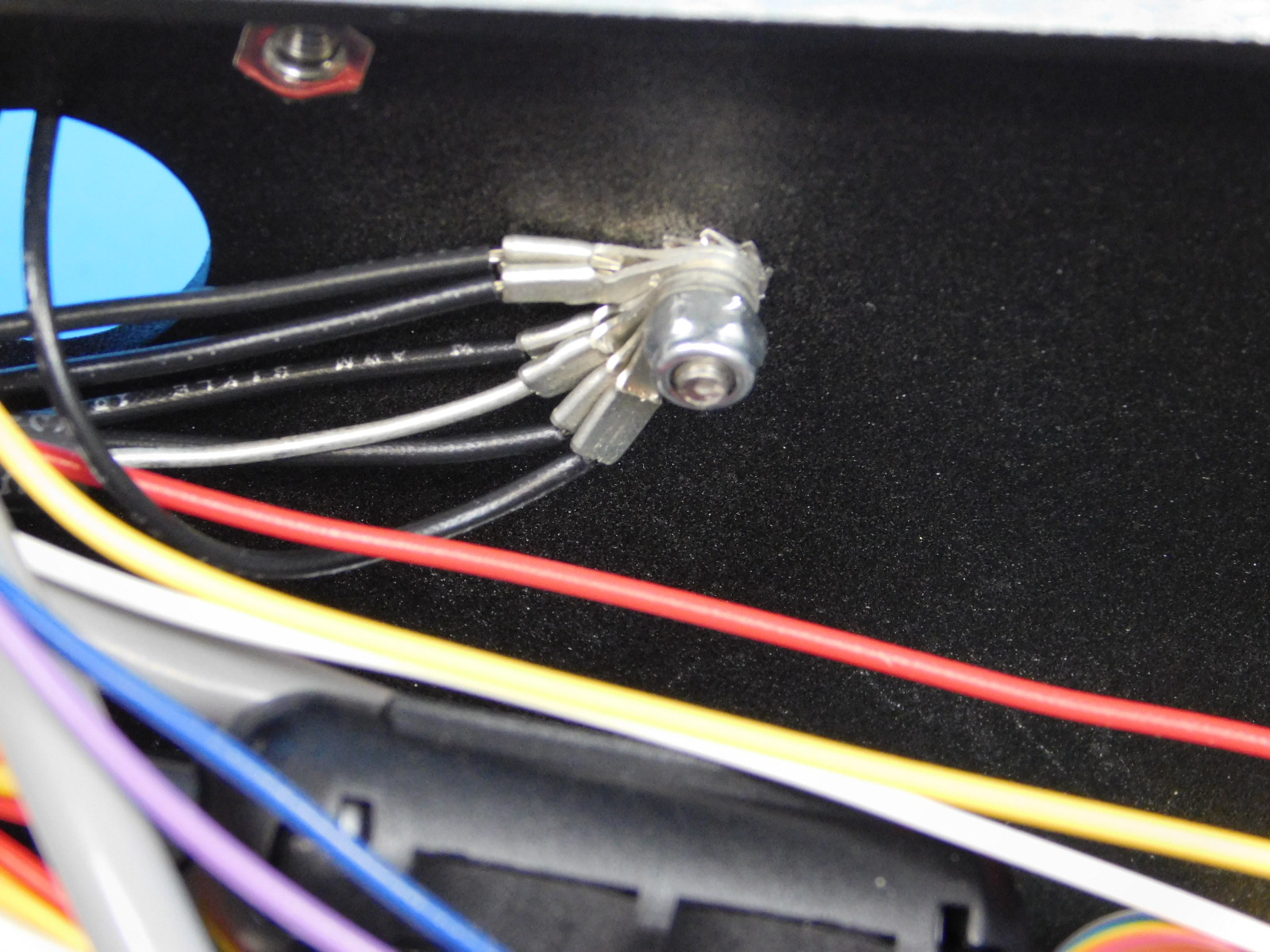
Install one Serrated Lock Washer [HD-WA0035] to the ground post on the bottom of the chassis
Attach the terminal rings from the two ground harnesses ([EL-HR0167] &[EL-HR0152])
Attach all three terminal rings from the CB YZ Harness [EL-HR0183] to the ground post on the bottom of the chassis and secure with one M3 Nyloc Nut [HD-NT0001]
Tighten securely.


Obtain one CB Z Max Harness [EL-HR0150]
Connect the end of the harness with the 3-pin connector to the Archim at the location shown.
Place the other end through the slot in the rear of the chassis.

Obtain one CB Bed Harness [EL-HR0184]
Connect the red lead with the 3 pin connector to the Z Min connector on the Archim; see diagram.
Connect the yellow lead with the 2 pin connector to the Bed Thermistor connector on the Archim; see diagram.

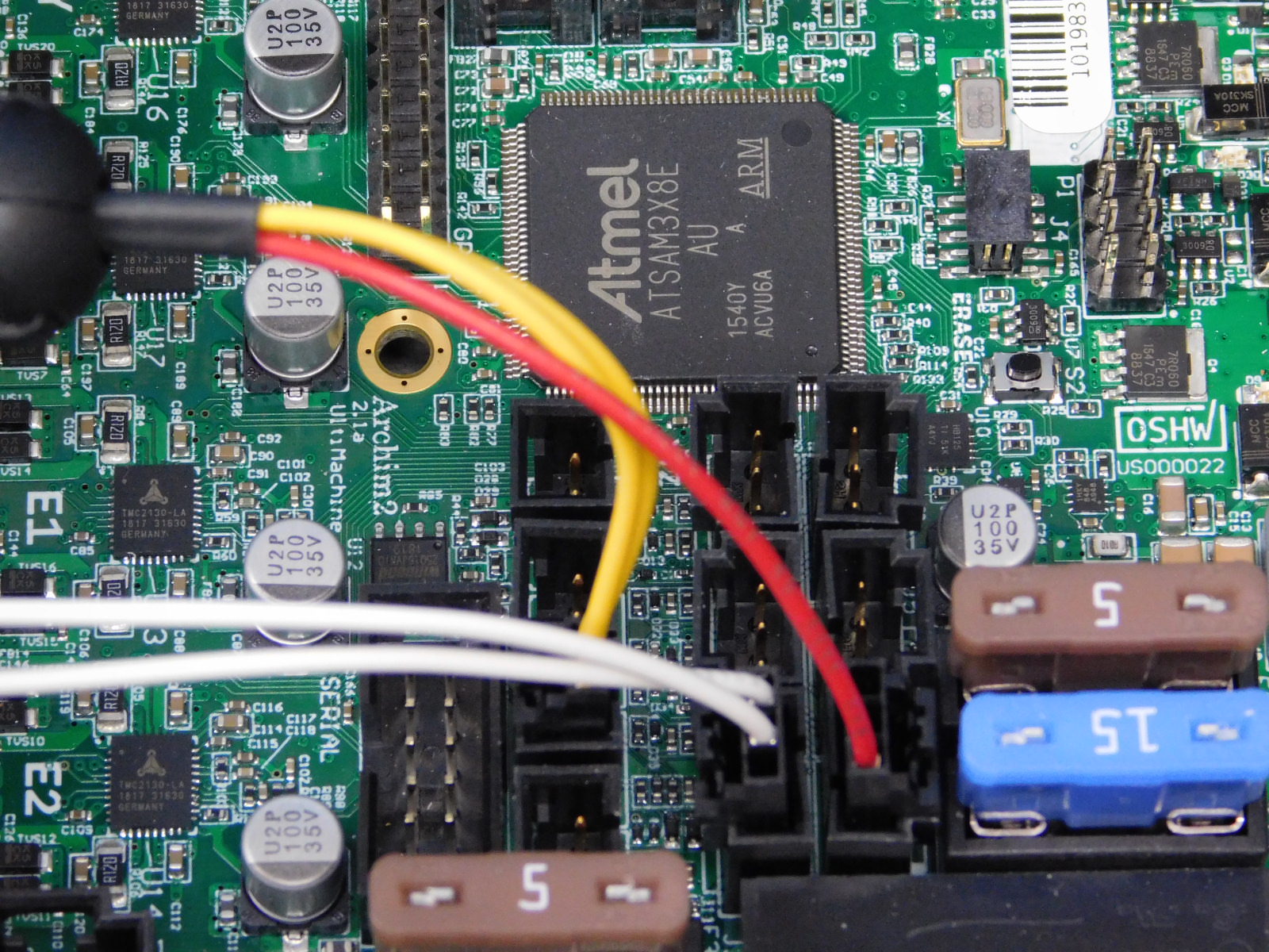
Obtain one CB Bed Power Harness [EL-HR0148]
Connect the terminal block end of the harness to the Archim; see diagram.
Place the other end of the harness through the slot in the rear of the chassis.
Obtain one CB X Harness [EL-HR0151]
Connect the 4 pin connector end of the harness to the X Motor connector on the Archim. This is located on the bottom left of the board.
See pin out diagram.

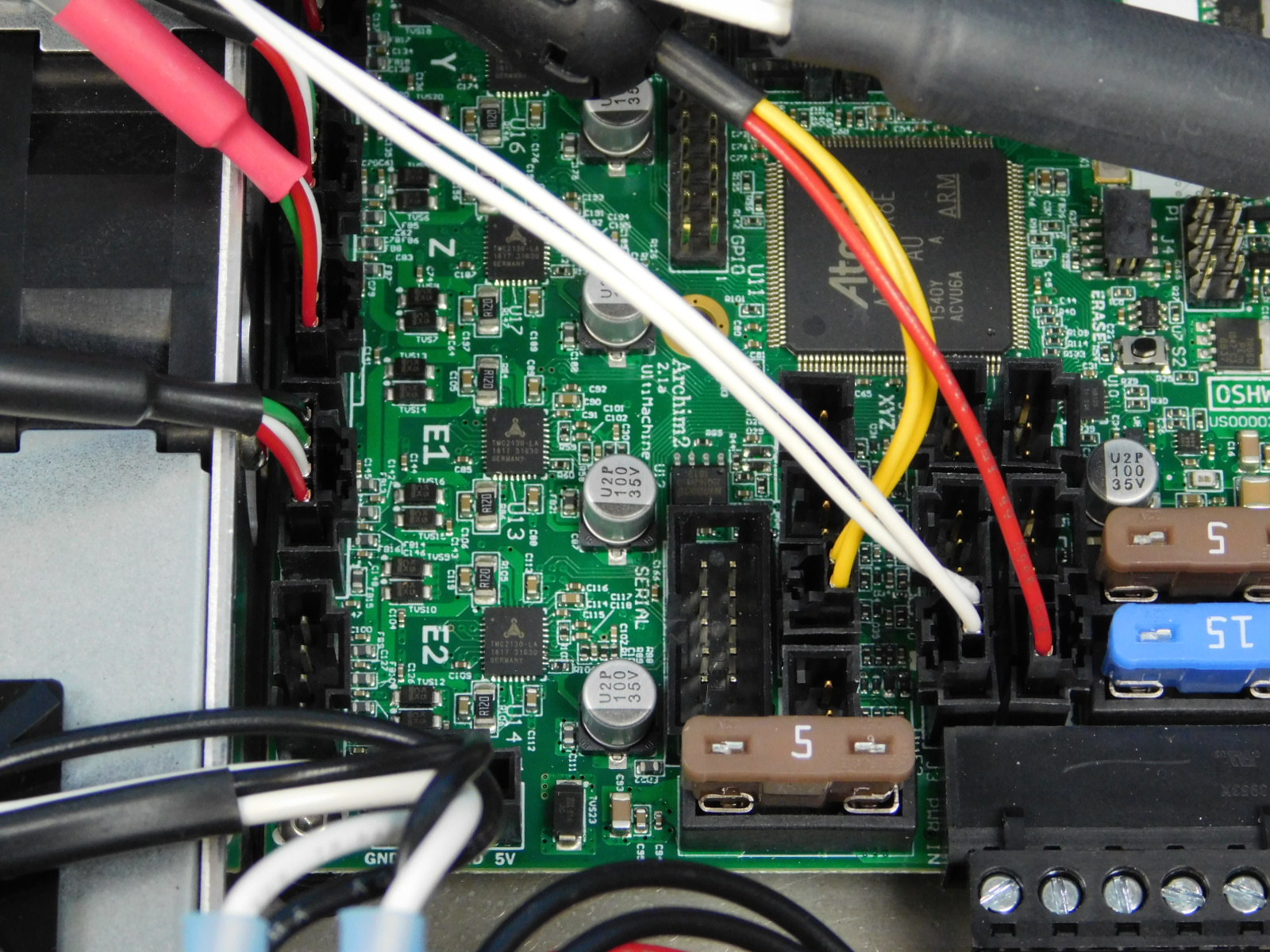
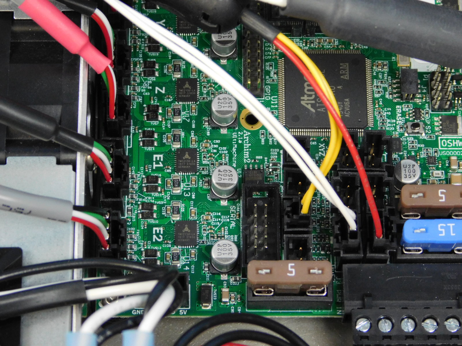
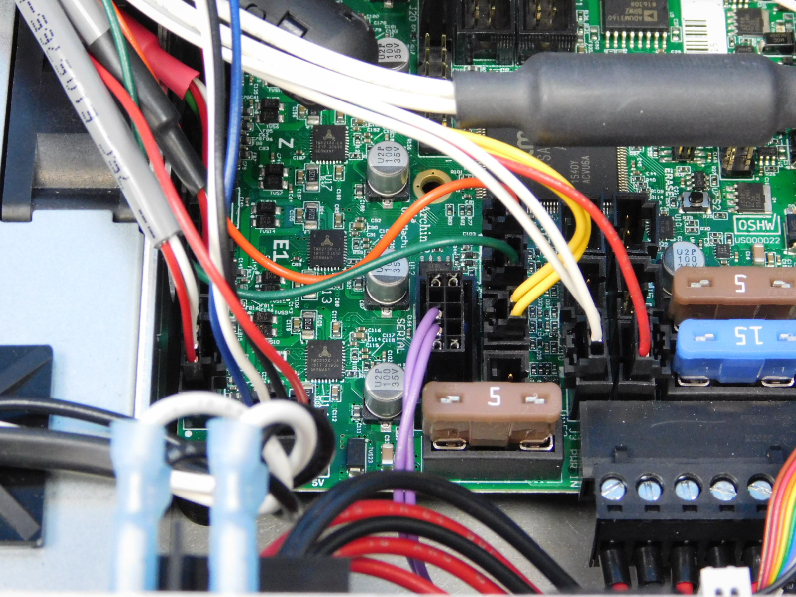
Obtain one CB Extruder Harness [EL-HR0153]
Connect the 4 pin connector with the black heat shrink to the E1 connector on the Archim.
Connect the gray shielded lead with 4 pin connector to the E2 connector on the Archim.
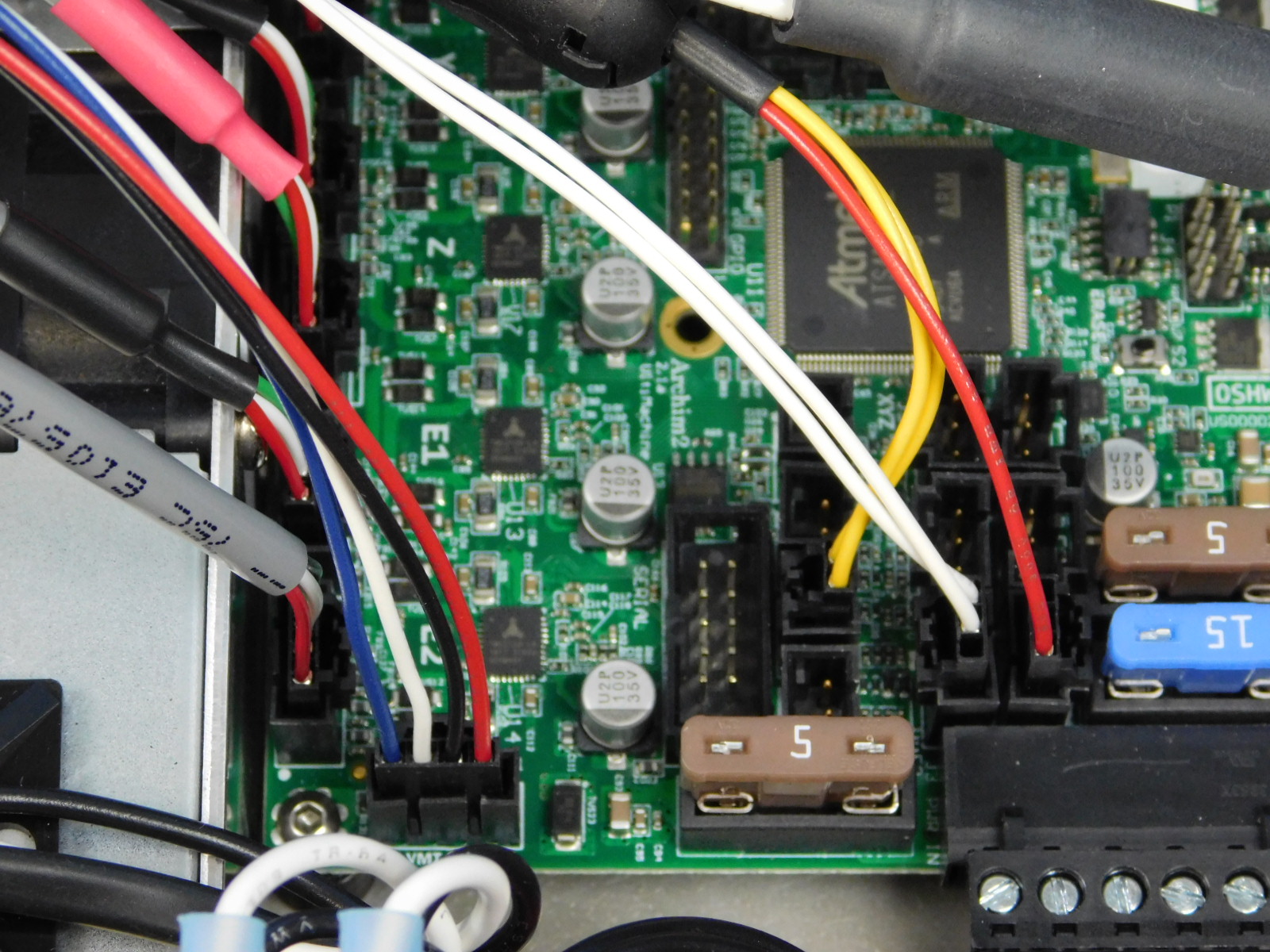
Connect the 4 pin connector (RED, WHITE, BLUE, BLACK) to the 4 pin connector to the right of the E2 connector.
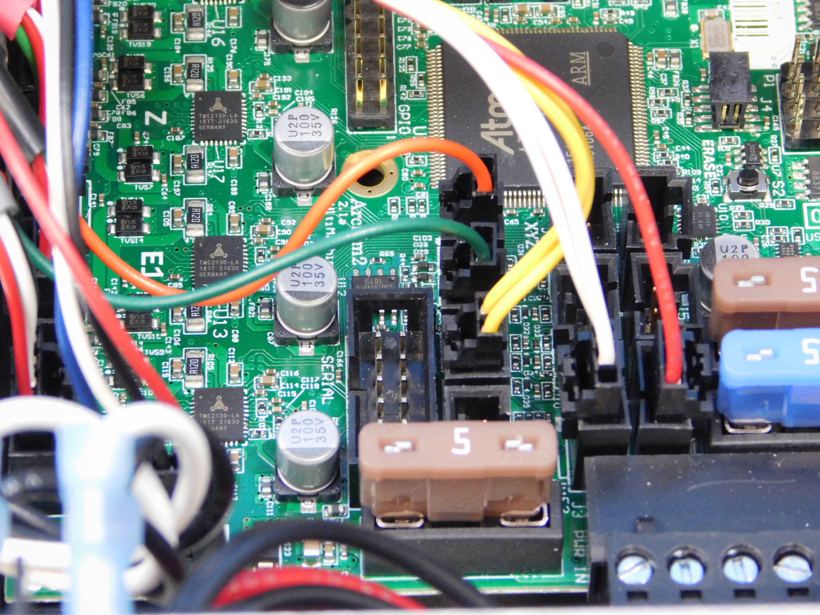
Connect the thermistor leads (both 2 pin connectors), orange on the left, green on the right. See pin out diagram.
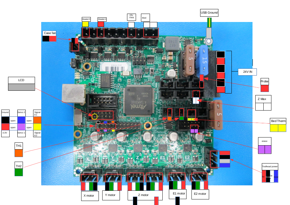
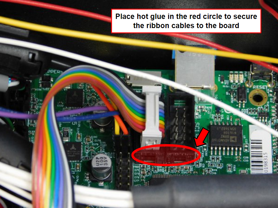
Place the ten pin connector on the left side of the 24 pin header with the RED/BLACK facing left, as pictured.
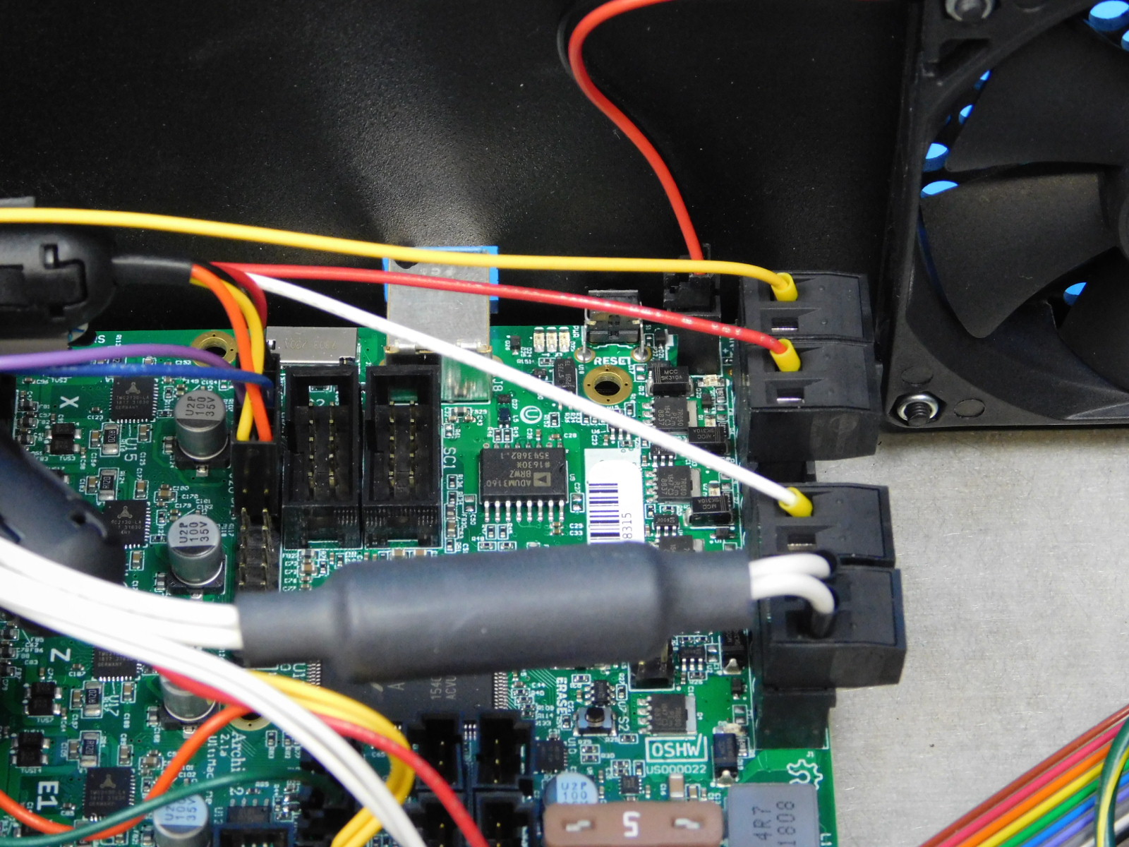
Carefully route the heater leads and 24v fan lead (all single lines in 2 position terminal blocks) so that no unnecessary tension is applied when the connector is plugged in.
Connect the yellow lead to the left-most terminal block position as pictured.
Connect the red lead to the next terminal block position to the right, as pictured.
Connect the white lead (24v Fan) to the open terminal block position closest to the CB Bed Power Harness, as pictured.

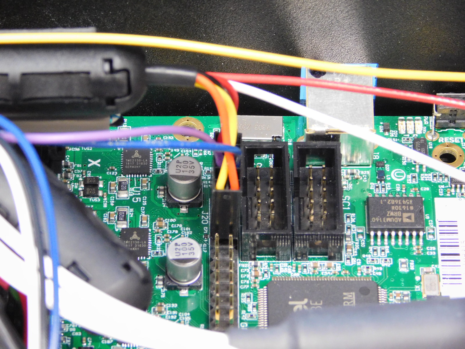
Obtain one Erase Switch Harness [EL-HR0156]
Route the harness against the chassis wall behind the CB DC Power Harness, as pictured.
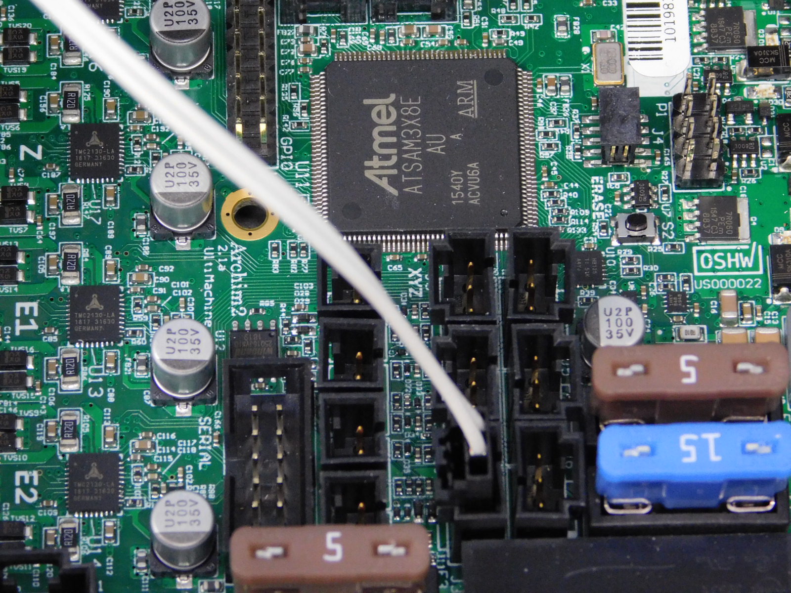
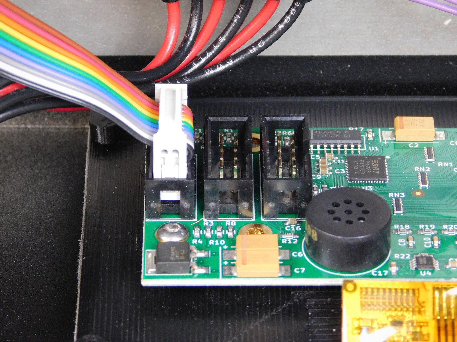
Connect the 10 pin connector to the 10 pin header below the thermistor connectors of the Archim; the side with the purple leads should be towards the bottom, see picture and diagram.
Connect the two purple spade connectors to the top two terminals of the erase switch, which is mounted on the USB Reader Assembly.


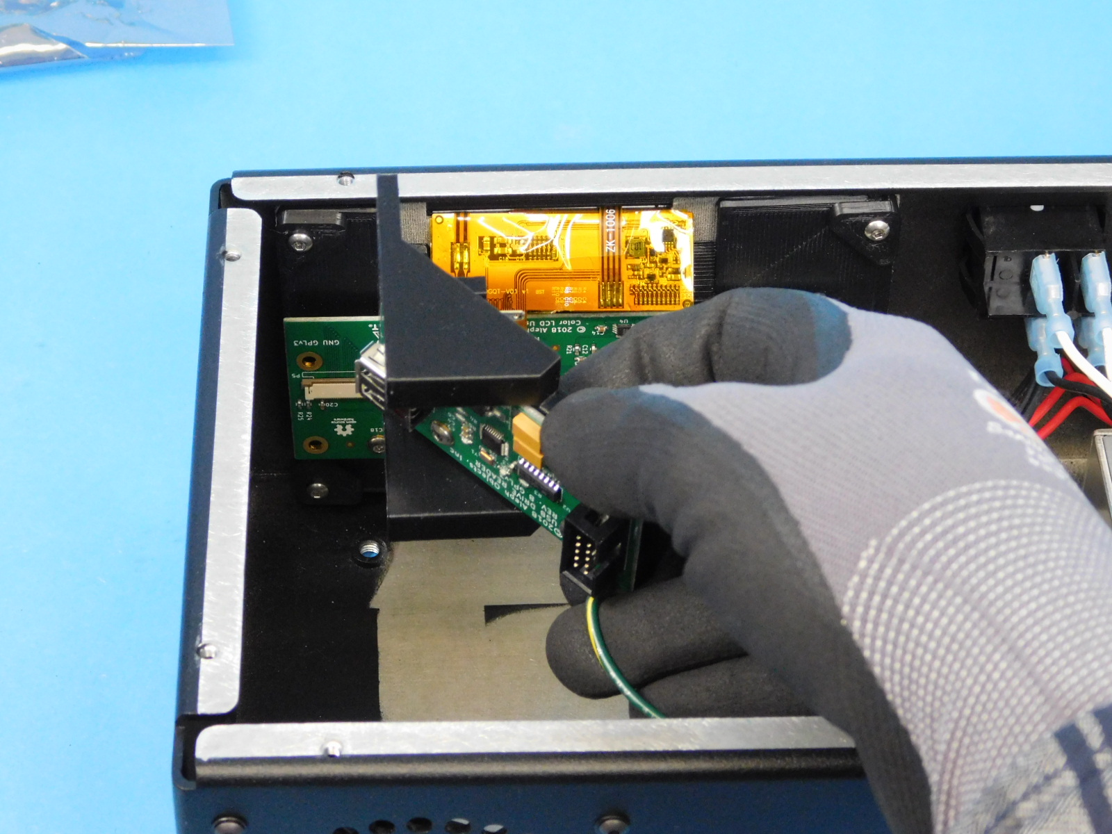
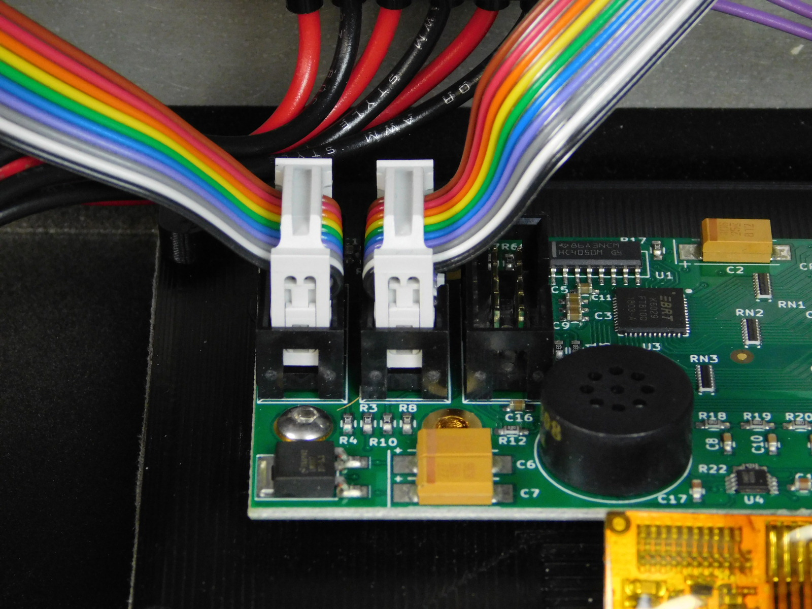
Obtain two (2) LCD/USB Harnesses [EL-HR0147]
Connect one first to the Archim at the location shown and then to the bottom 10 pin header of the LCD Board.
Connect another from the middle 10 pin connector on the LCD Board to the 10 pin connector on the USB Reader board.

Gather all of the terminal rings, you should have 5 of them.
Apply one Serrated Lock Washer [HD-WA0035] to the ground post on the rear of the chassis.
Stack all 5 terminal rings on the post and secure with one M3 Nyloc Nut [HD-NT0001]
Tighten securely
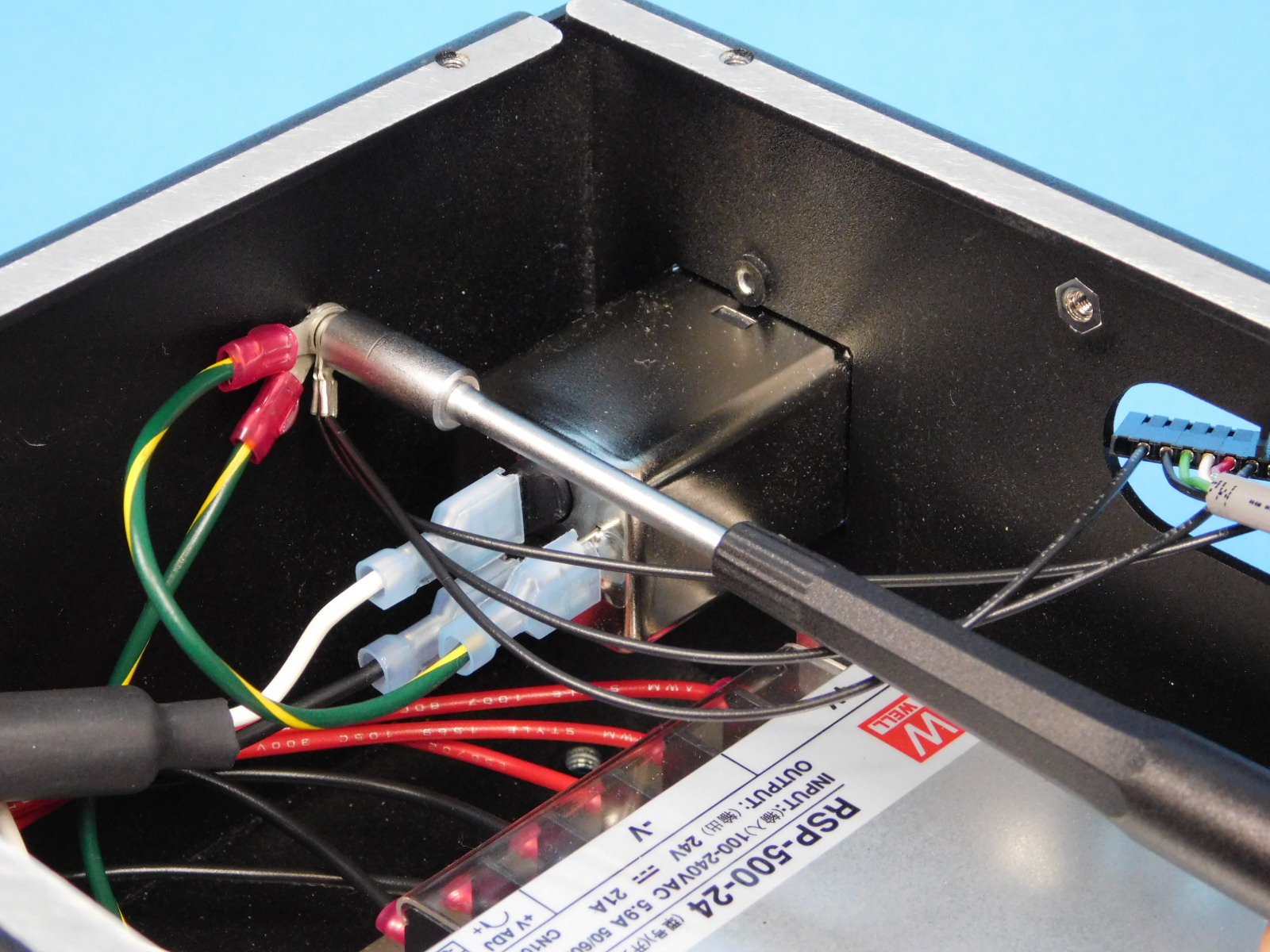
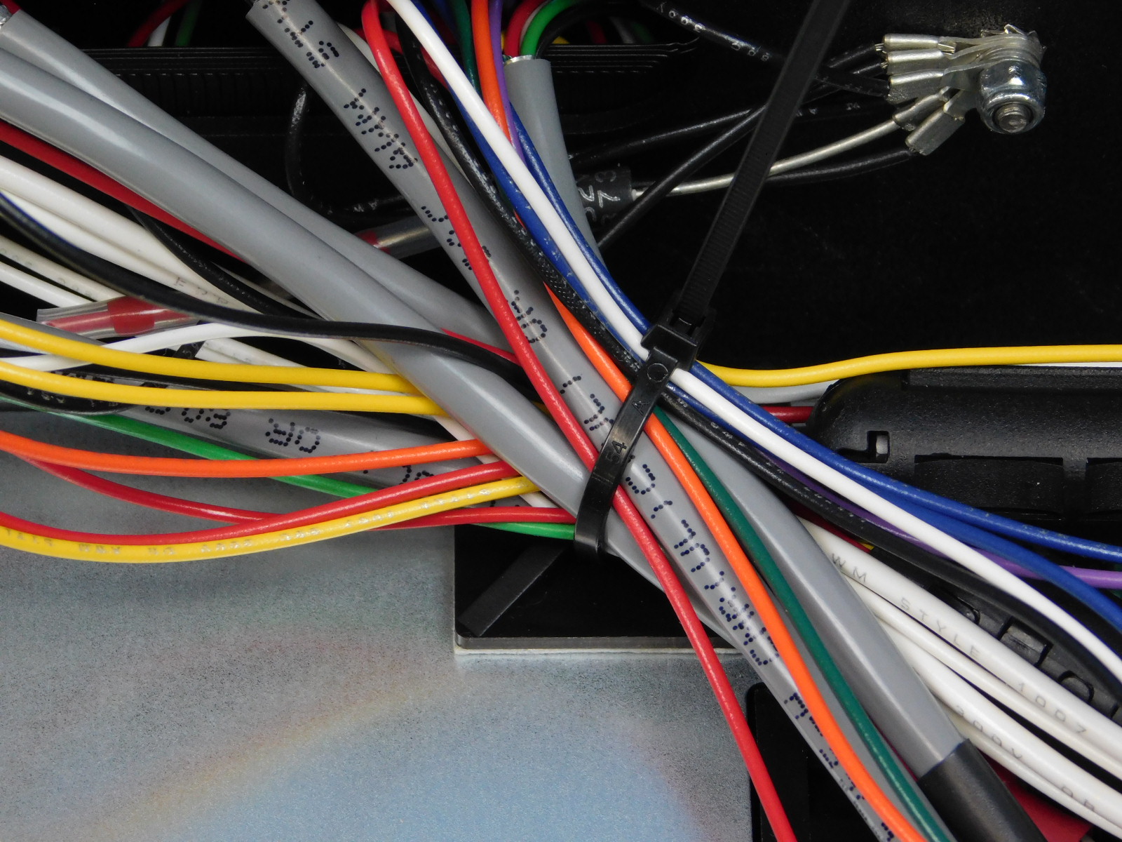
Secure the harnesses to the tie down on the PSU using one zip tie [HD-MS0058] as pictured. It is not necessary to capture all of the grounds inside the zip tie.
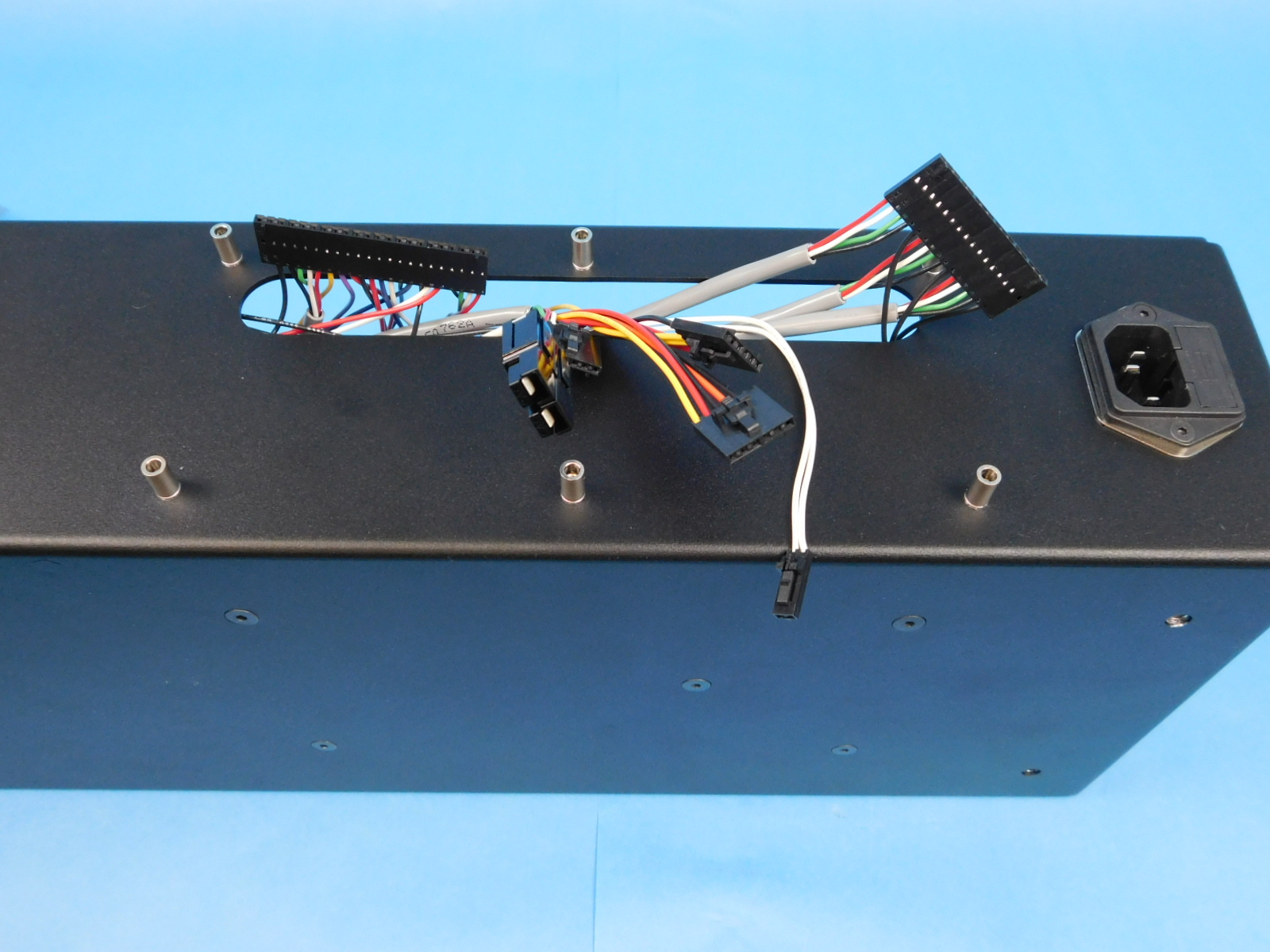
Flip the assembly so that the back of the chassis faces up
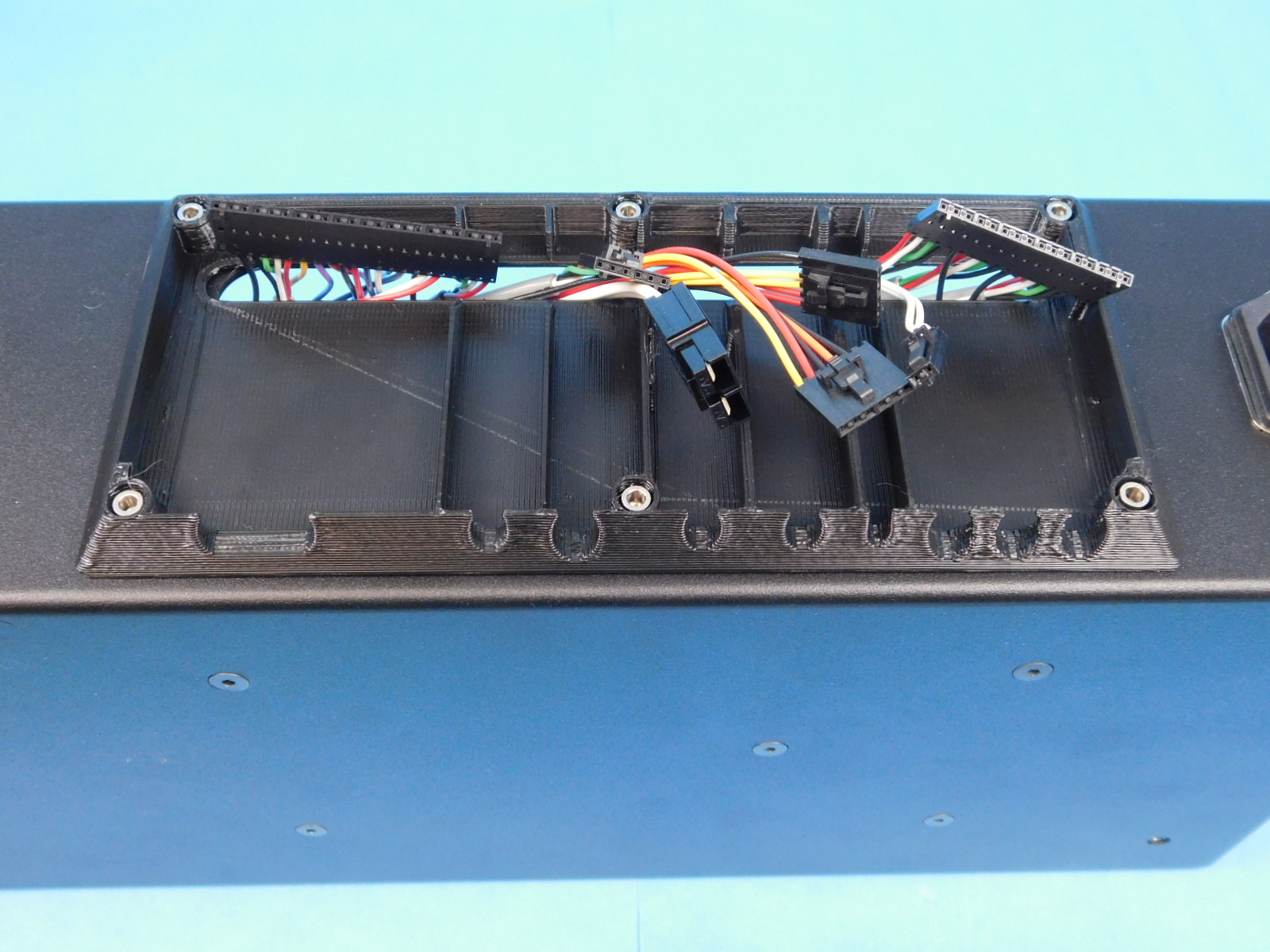
Obtain one Interconnect Housing [PP-GP0407]
Place it over the posts on the rear of the chassis with the slot in the printed part aligned with the slot in the chassis.
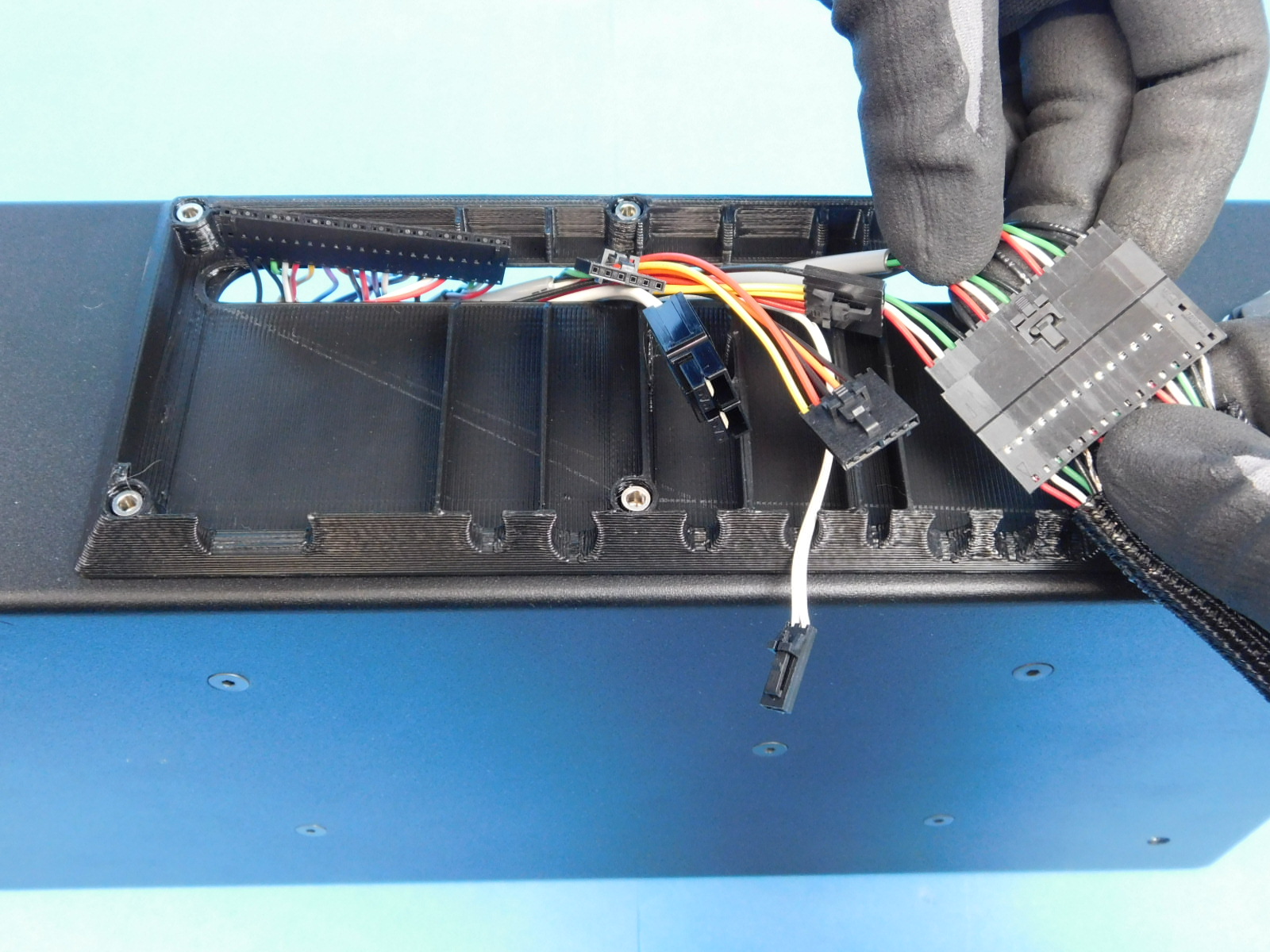
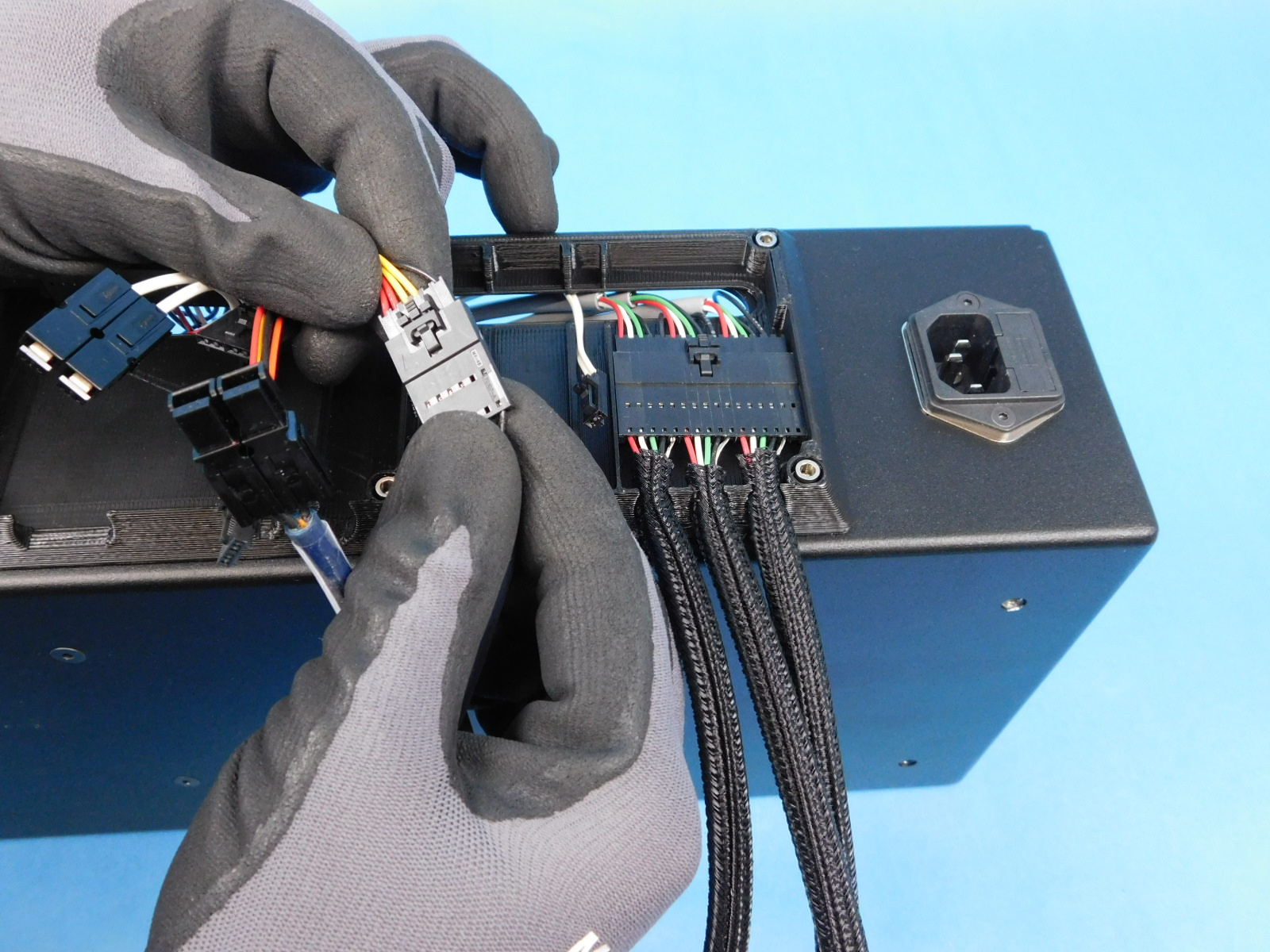
Obtain one YZ Harness, Assembled [EL-HR0143]
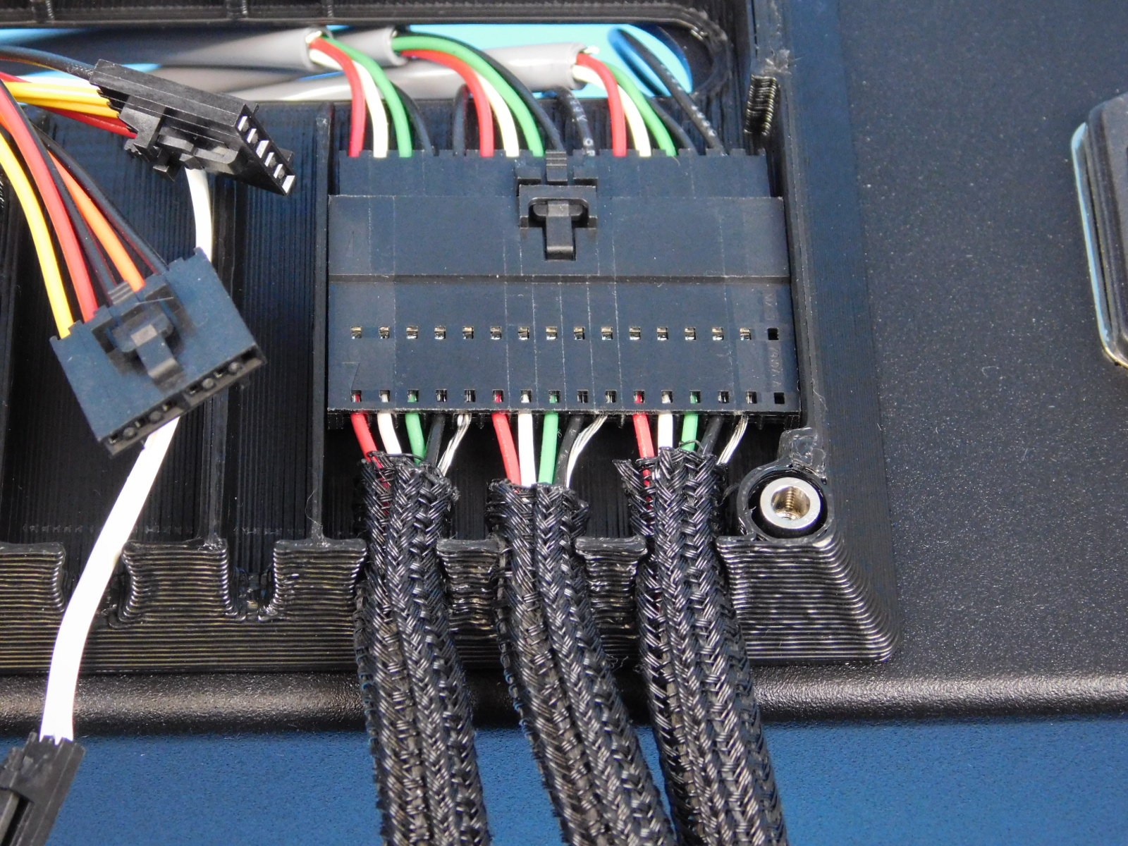
Pull the connector of the internal YZ Harness [EL-HR0183] through the slot in the rear of the chassis and connect the large connector of the external YZ Harness [EL-HR0143]
Push the connector into the wide slot in the Interconnect Housing [PP-GP0407] and carefully push the braided loom of all 3 leads into their respective slots.
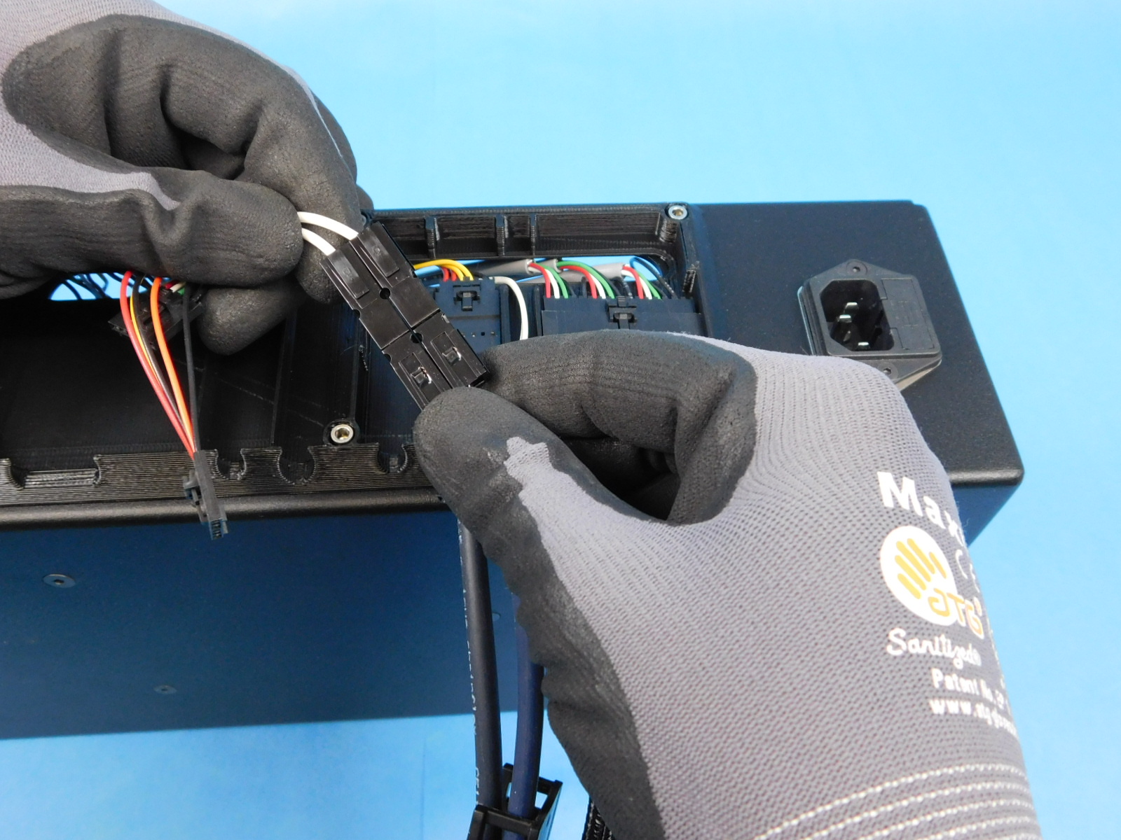
Obtain one Bed Harness [EL-HR0140]
Pull the CB Bed Power Harness [EL-HR0148] through the slot in the rear of the chassis.
Connect the two Anderson connectors and press them into the retaining feature of the Interconnect Housing [PP-GP0407] as pictured.
Pull the CB Bed Harness [EL-HR0184] through the slot in the rear of the chassis and connect it to the Bed Harness [EL-HR0140]
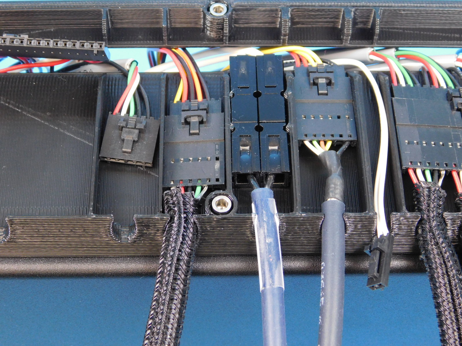
Seat both connectors in the appropriate channels of the Interconnect Housing [PP-GP0407] as pictured.

Obtain one Filament Sensor Harness [EL-HR0140]
Pull the internal filament sensor harness (part of [EL-HR0153]) through the slot in the rear of the chassis.
Connect the 6 pin connector of the Filament Sensor Harness [EL-HR0144] to the internal filament sensor harness.
Place the cable with the loom in the channel on the Interconnect Housing [PP-GP0407] as pictured.
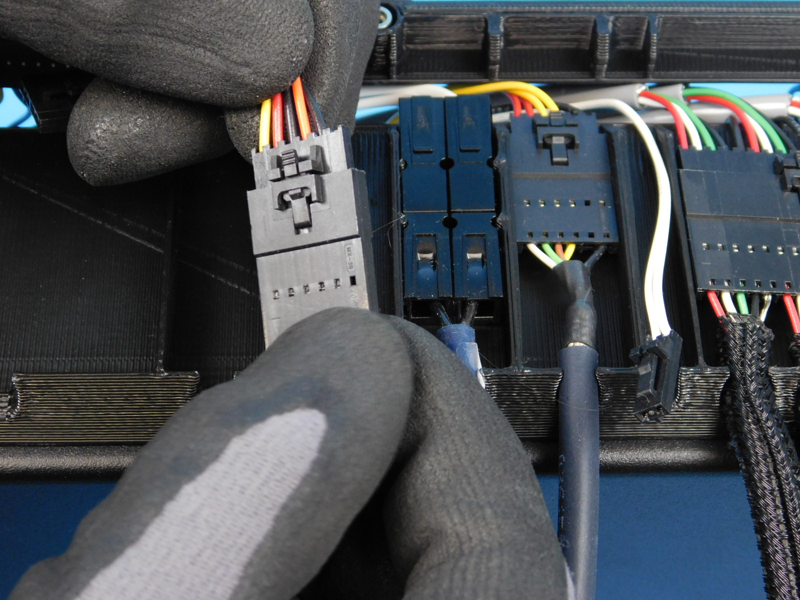
Obtain one Extruder X Harness [EL-HR0141]
Pull the CB X Harness [EL-HR0151] through the slot in the rear of the chassis.
Connect the 6 pin connector of the Extruder X Harness [EL-HR0141] to the CB X Harness [EL-HR0151]
Pull the large connector of the CB Extruder Harness [EL-HR0153] through the slot in the rear of the chassis and connect it to the Extruder X Harness [EL-HR0141]
Fit both connectors and their cables into the respective slots on the Interconnect Housing [PP-GP0407] as pictured.


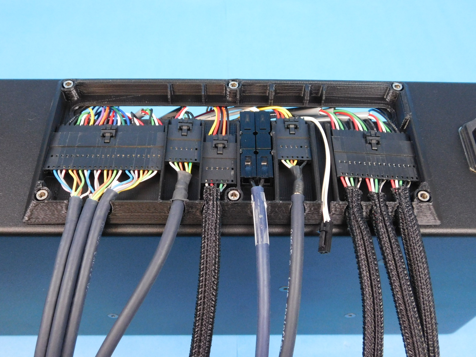
Obtain one Interconnect Housing Cover [PP-FP0153]
Pull the 2 pin connector of the CB Z Endstop Harness [EL-HR0150] through the slot in the rear of the chassis and lay it in the channel as pictured. Place a piece of blue tape [OF-CS0373] over the wires.
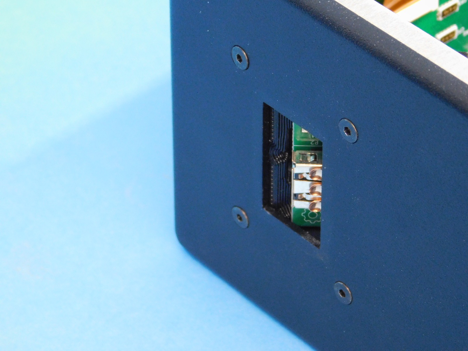
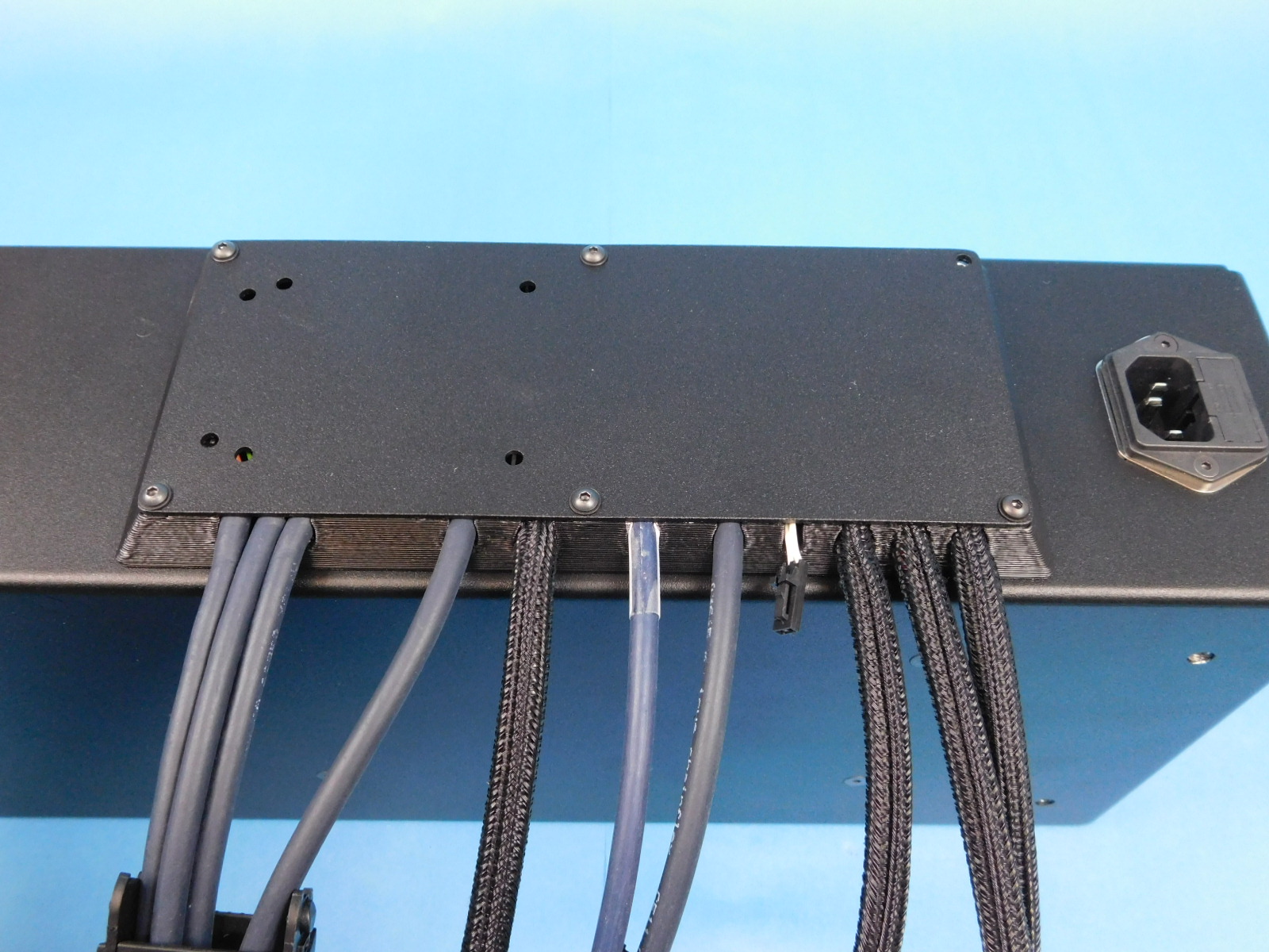
Place the Interconnect Cover [PP-FP0153] over the cables with the extra holes towards the top.
Ensure no wires are pinched, pay special attention to the Z Max Wire
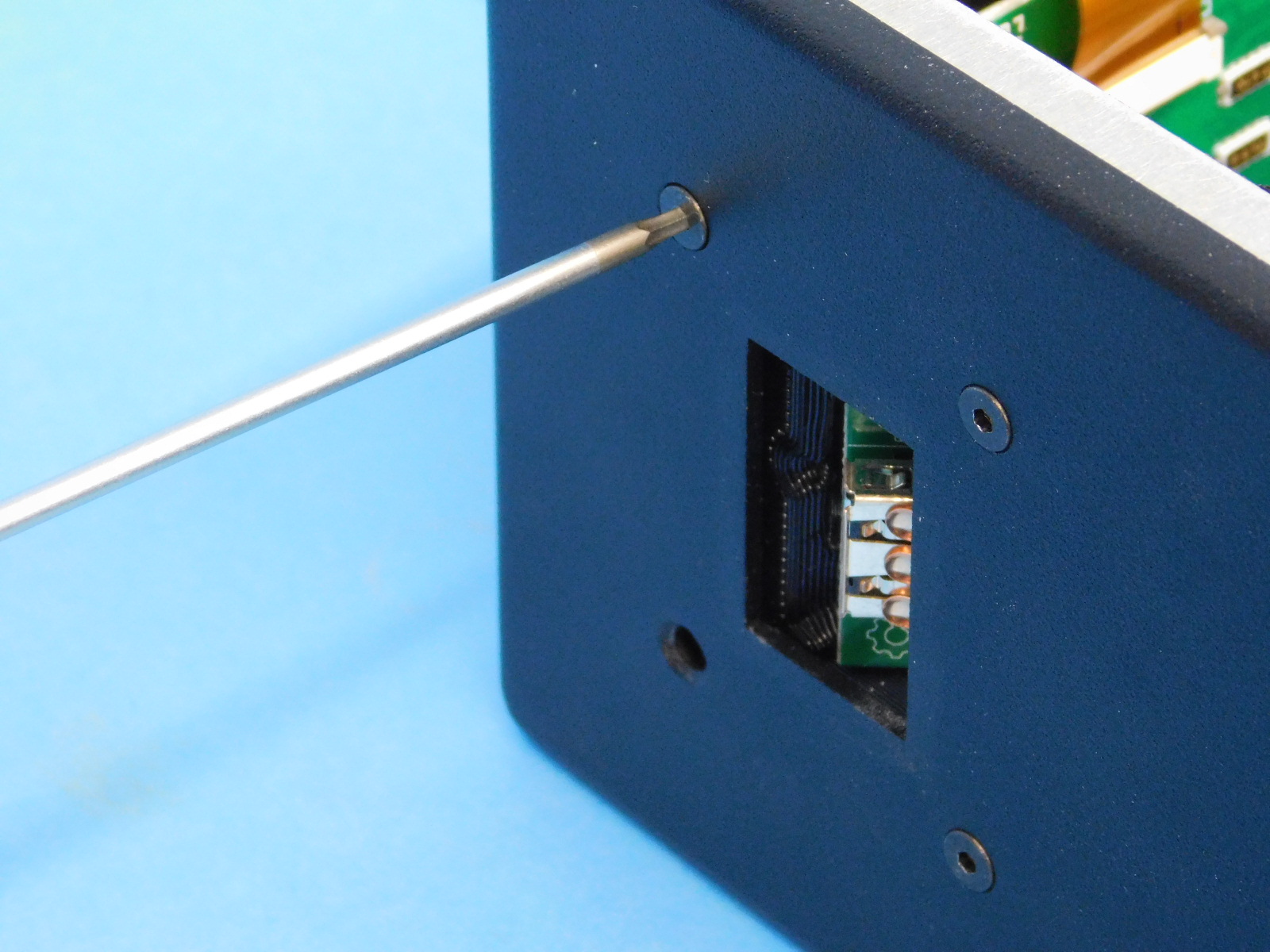
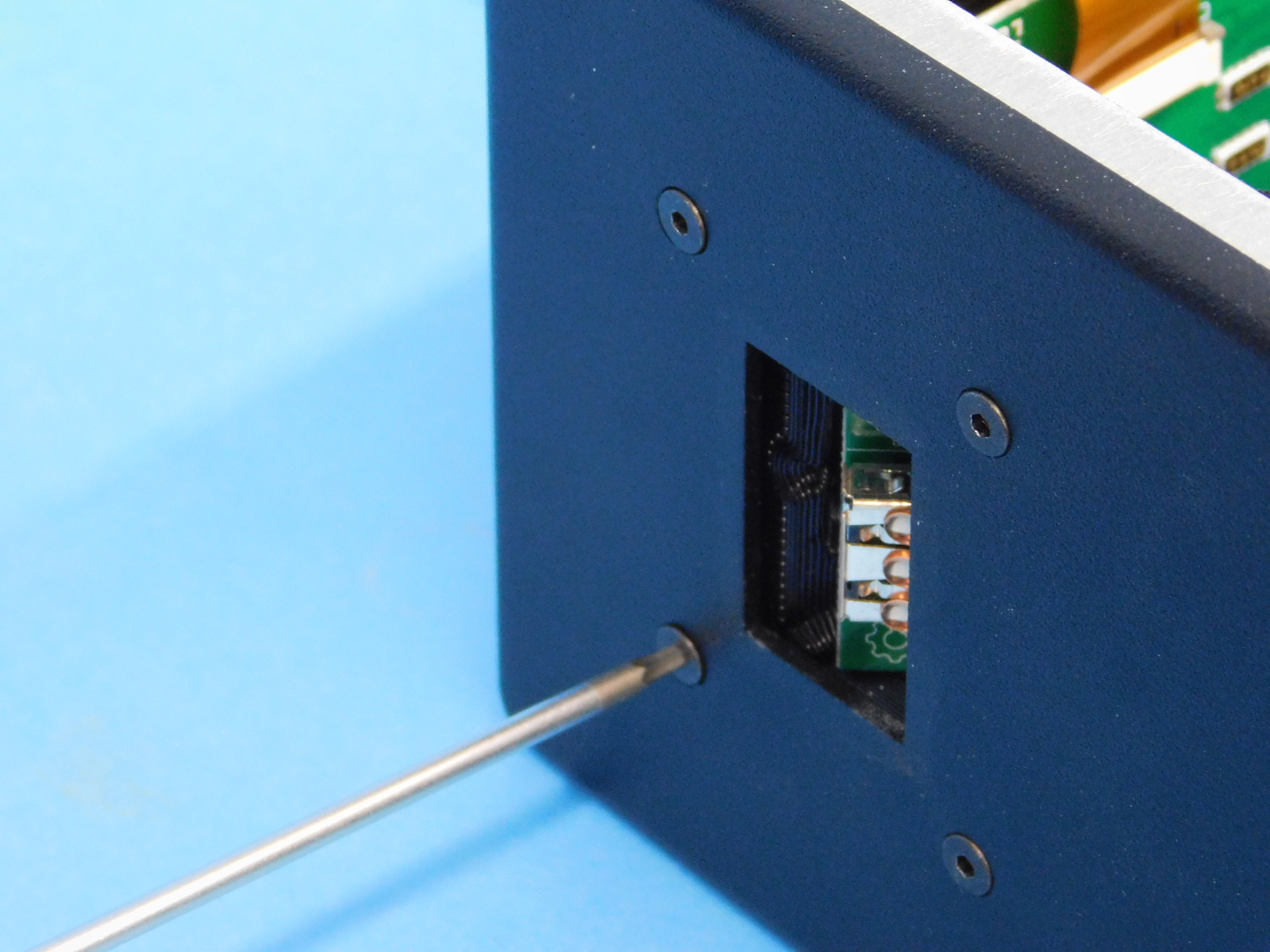
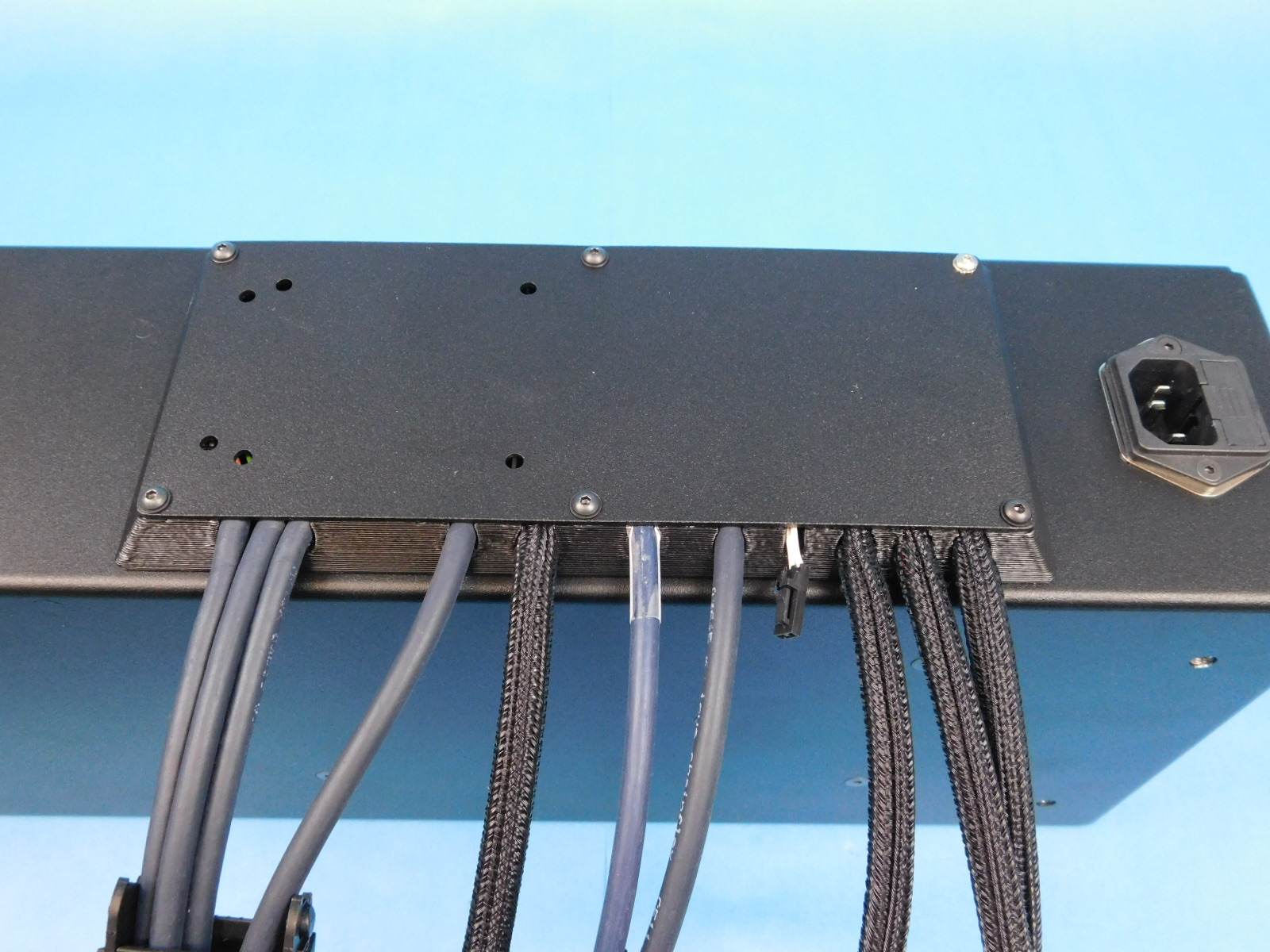
Secure the Interconnect Cover [PP-FP0153] using five (5) M3x8 BHCS [HD-BT0137] with washers [HD-WA0038] at the highlighted locations.
Torque to 5in-lbs
Use one (1) M3x10 Stainless BHCS [HD-BT0234] and one Serrated Lock Washer [HD-WA0035] at the location highlighted.
Torque to 5in-lbs


Obtain one Electronics Cover [PP-FP0150]
Place the Electronics Cover [PP-FP0150] on the chassis with the LulzBot logo towards the top of the chassis.
Secure using ten (10) M3x6 BHCS [HD-BT0140] with washers [HD-WA0038]
Torque to 5in-lbs

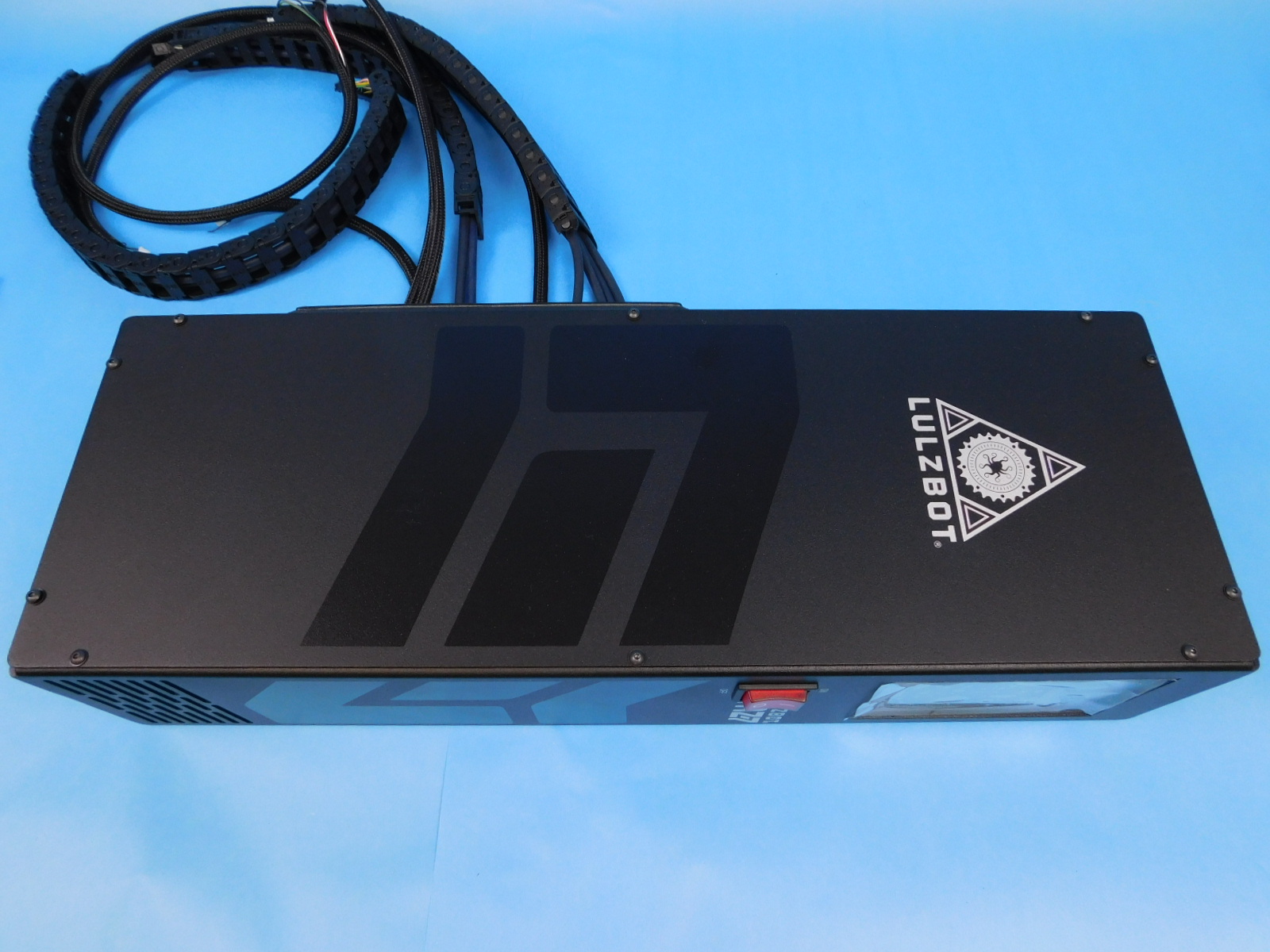
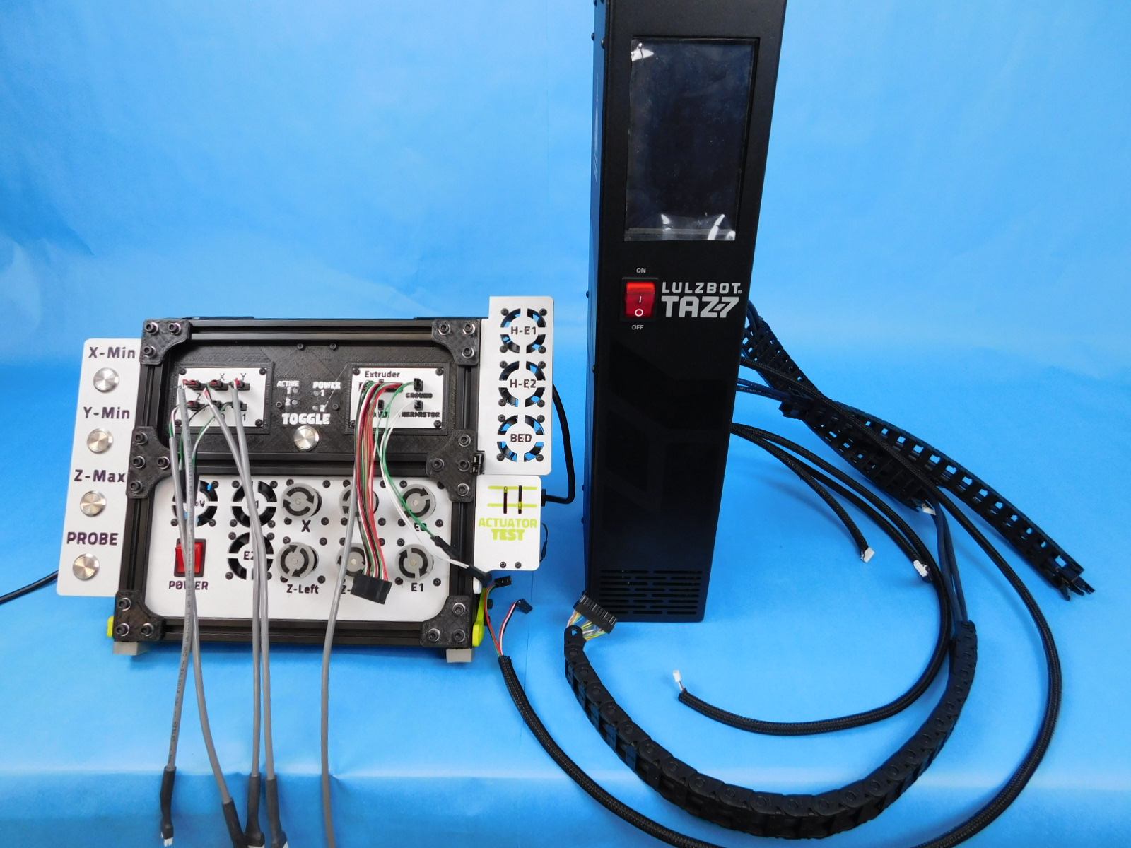
Now that the Control Box is fully assembled, proceed to Control Box Testing