Open HardwareAssembly Instructions
Guides for installation and assembly of the LulzBot line of products made by FAME 3D LLC.
Guides for installation and assembly of the LulzBot line of products made by FAME 3D LLC.
1x- [DC-LB0208] Electric Warning Sticker, French
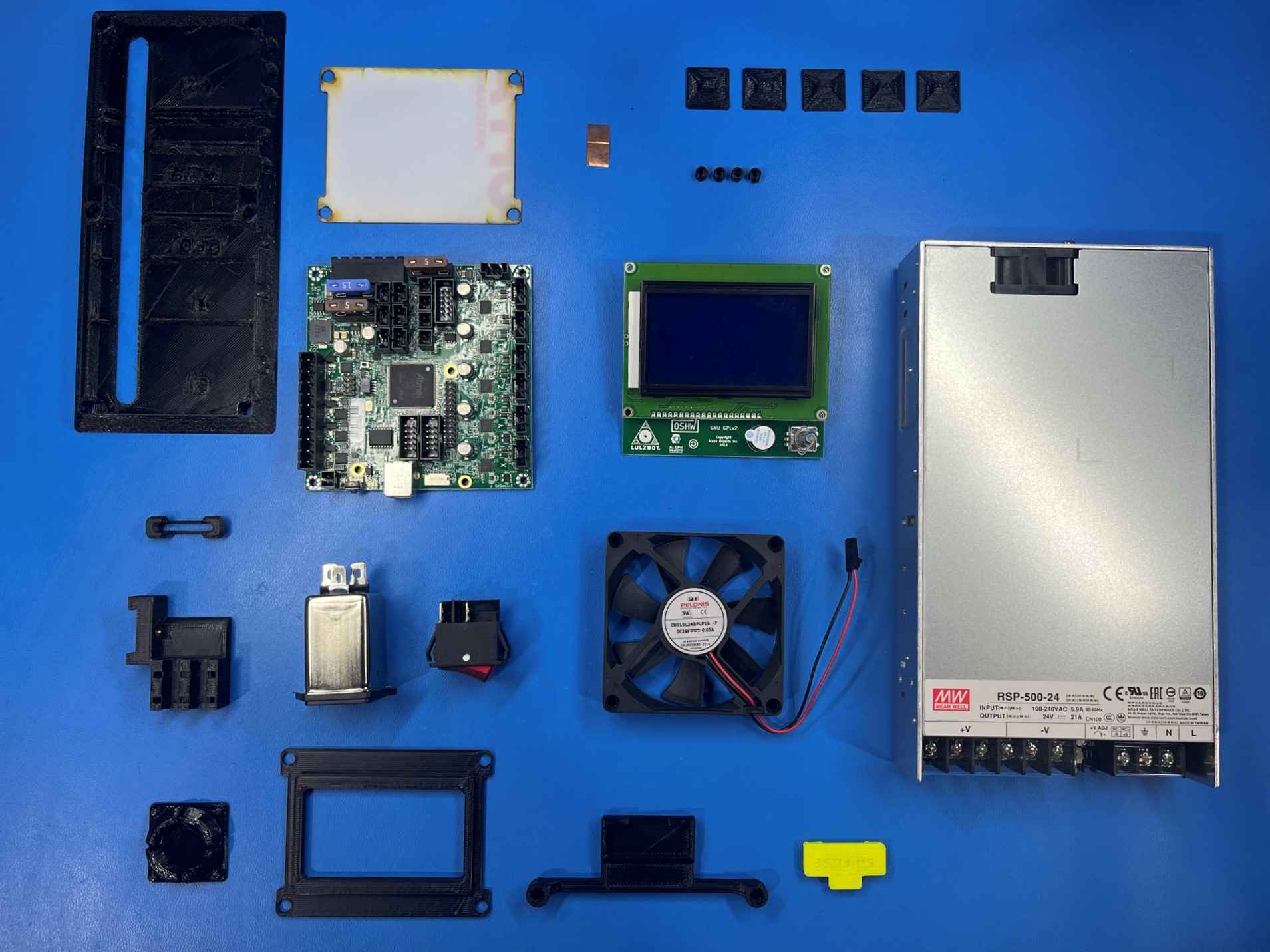
1x- [EL-FA0061] CB Case Fan Assembly
1x- [EL-MS0346] MOD PWR ENTRY INLET w/FUSE 6A
5x- [EL-MS0235] Surface Mount Fuse 125V 5A
1x- [EL-PS0031] AC-DC Power Supply 500W
1x- [EL-SW0023] SWITCH ROcker DPST 20A 250V
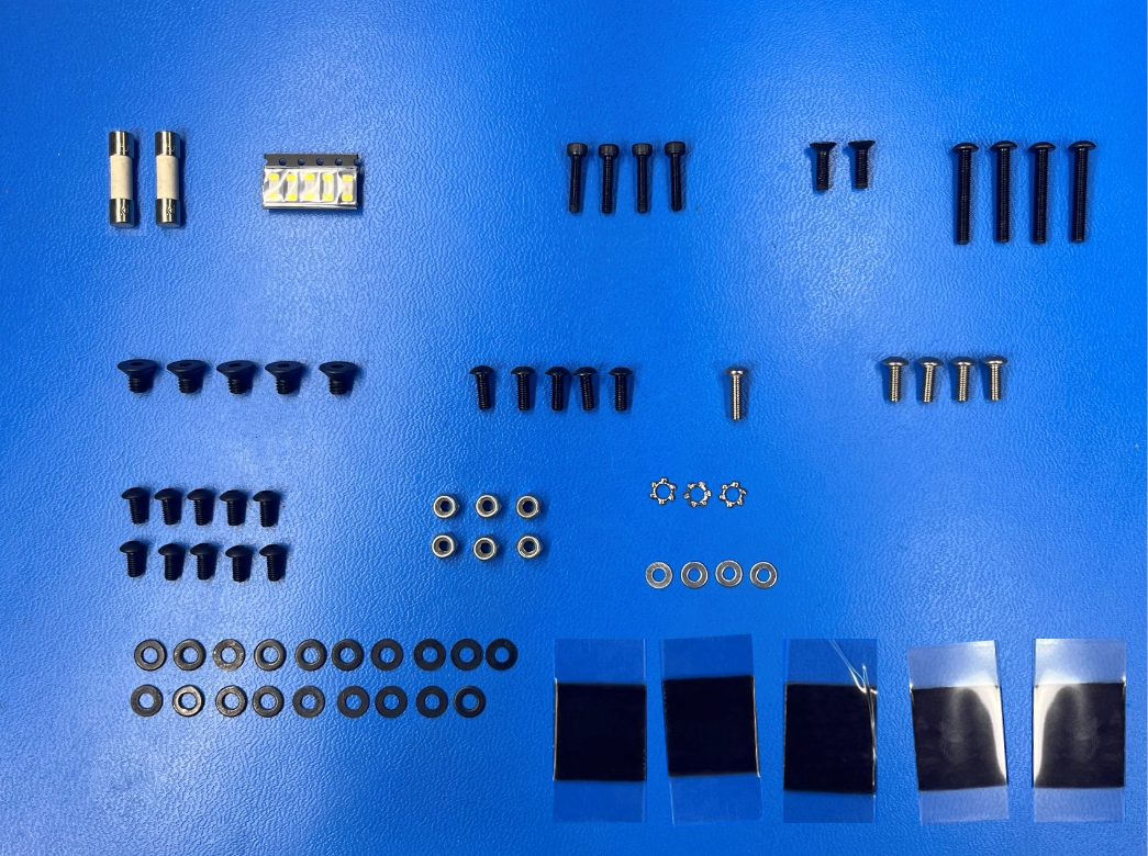
4x- [HD-BT0054] M2.5x12 SHCS, Black-Oxide
4x- [HD-BT0104] M3x8 BHCS, SST
2x- [HD-BT0116] M3x10 FHCS, Black-Oxide
5x- [HD-BT0137] M3x8 BHCS, Black-Oxide
10x- [HD-BT0140] M3x6 BHCS Black-Oxide
4x- [HD-BT0171] M3x20 BHCS, Black-Oxide
5x- [HD-BT0155] M4x6 FHCS, Black-Oxide
1x- [HD-BT0234] M3x10 BHCS, SST
8x- [HD-MS0058] Wire Tie, 8" Black
5x- [HD-MS0571] Adhesive, Pre-Cut Squares
6x- [HD-NT0001] M3 Lock Nut
4x- [HD-WA0013] M2.5 Washer
3x- [HD-WA0035] M3 Lock Washer, SST
19x- [HD-WA0038] M3 Washer
2x- [EL-MS0347] Fuse Ceramic 6.3A 250VAC
1x - [EL-MS0560] Copper Foil Electrical Tape Conductive Adhesive 10mm
1x- [PC-AS0041] Plastic Laser Cut LCD Cover
1x- [PC-AS0056] LCD LB_GLCD
1x- [PC-BD0094] RAMBo Electronics Board
1x- [PP-FP0163] TAZ WorkHorse Electronics Chassis
1x- [PP-FP0164] TAZ WorkHorse Electronics Chassis Cover
1x- [PP-FP0153] TAZ Interconnect Cover
4x- [PP-GP0089] LCD Spacer
1x- [PP-GP0230] LCD Bezel
1x- [PP-GP0235] SD Card Bezel
1x- [PP-GP0438] Interconnect Housing
1x- [PP-GP0440] Y Cable Mount
1x- [PP-GP0463] 5A Fuse Sleeve
1x- [PP-GP0464] 5A Fuse Mount
5x- [PP-GP0483] Universal Cable Tie Holder
1x- [PP-GP0496] Control Box Extruder Plug

2x- [EL-HR0147] LCD-USB Harness
1x- [EL-HR0148] CB Bed Power Harness
1x- [EL-HR0152] CB PSU to Ground Green Harness
1x- [EL-HR0154] DC Power Harness
1x- [EL-HR0157] CB Switch to PSU Harness
1x- [EL-HR0167] Plug to ground green
1x- [EL-HR0168] Plug to switch black and white with ferrite
1x- [EL-HR0173] CB X Harness
1x- [EL-HR0174] Bed Power Harness
1x- [EL-HR0175] CB Extruder Harness
1x- [EL-HR0177] CB Y End-Stop Harness
1x- [EL-HR0178] Extruder Harness
1x- [EL-HR0179] X Harness
1x- [EL-HR0180] Y Bed Harness
1x- [EL-HR0181] YZ End Harness
1x- [EL-HR0183] CB YZ Harness
1x- [EL-HR0184] CB Bed Harness
1x- [EL-HR0185] CB Z Endstop Harness

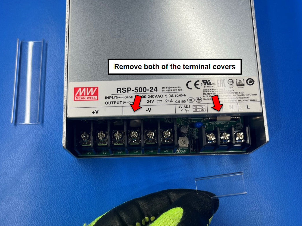
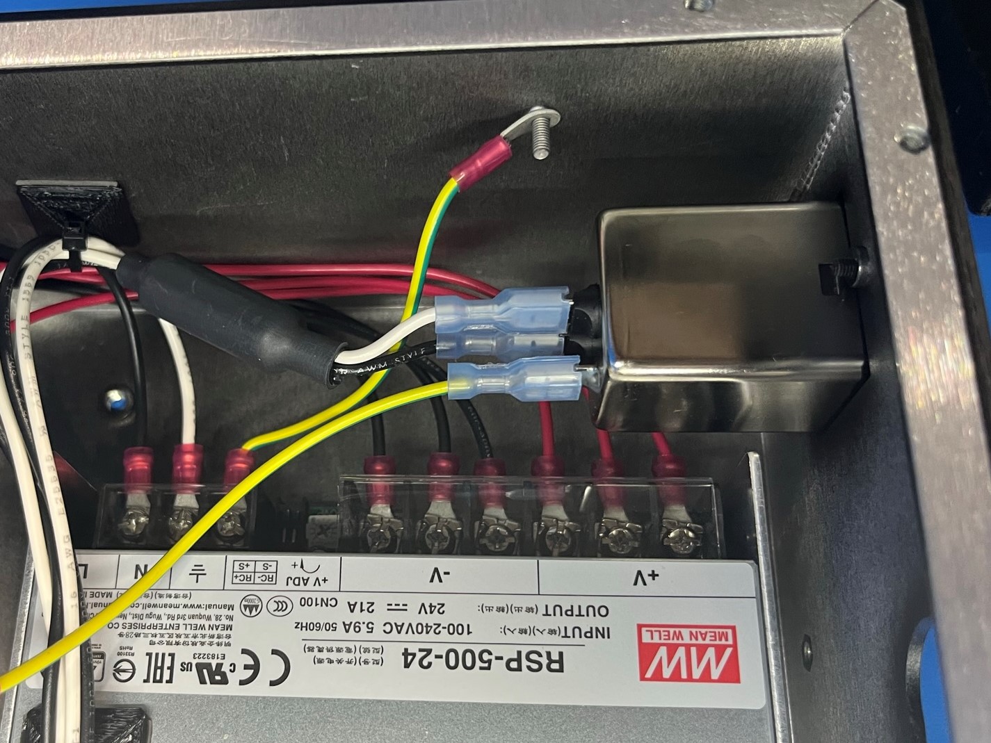
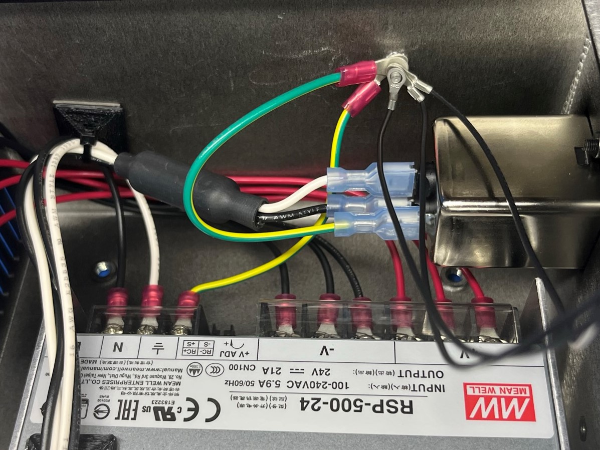
Remove both of the terminal covers from the power supply [EL-PS0031] and set them a side. Once the covers are removed loosen all 9 terminals.
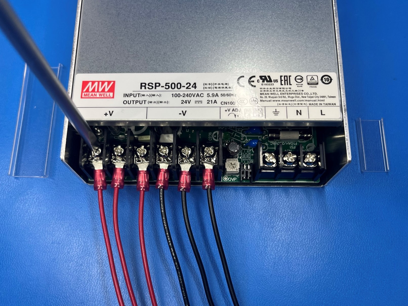
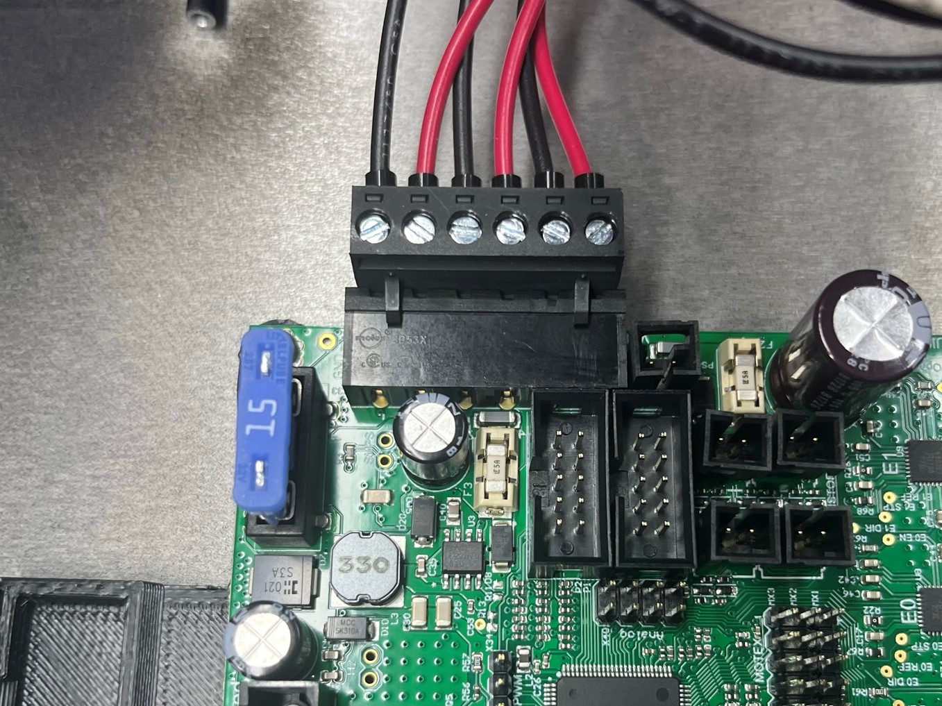
Connect the CB DC power harness [EL-HR0154] to the power supply. Slide the three black wires under the terminals marked “-V” and the red wires under the terminals marked “+V”.
Then tighten the terminal screws to secure the harness
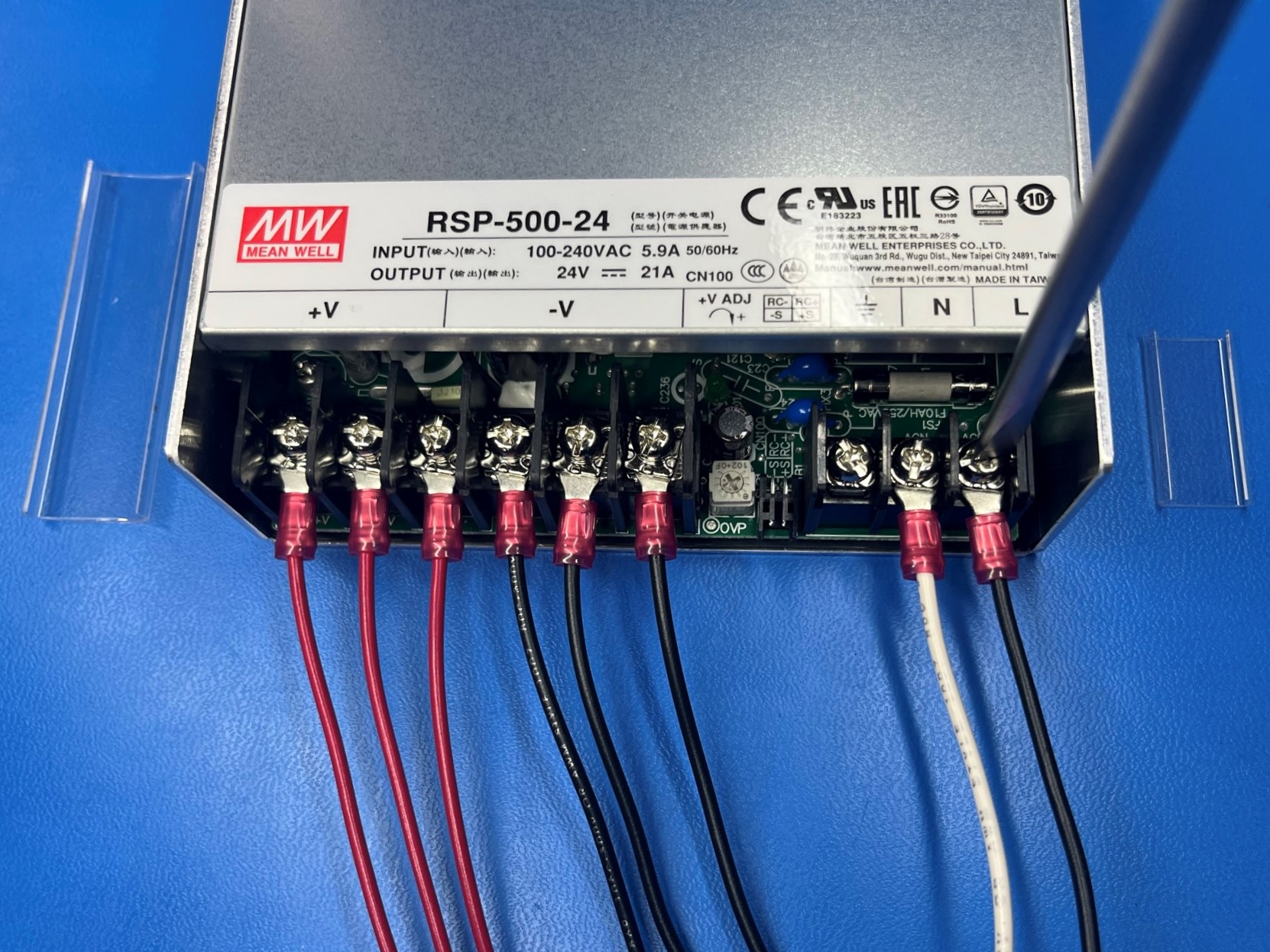
Now connect the CB switch to PSU harness[EL-HR0157].
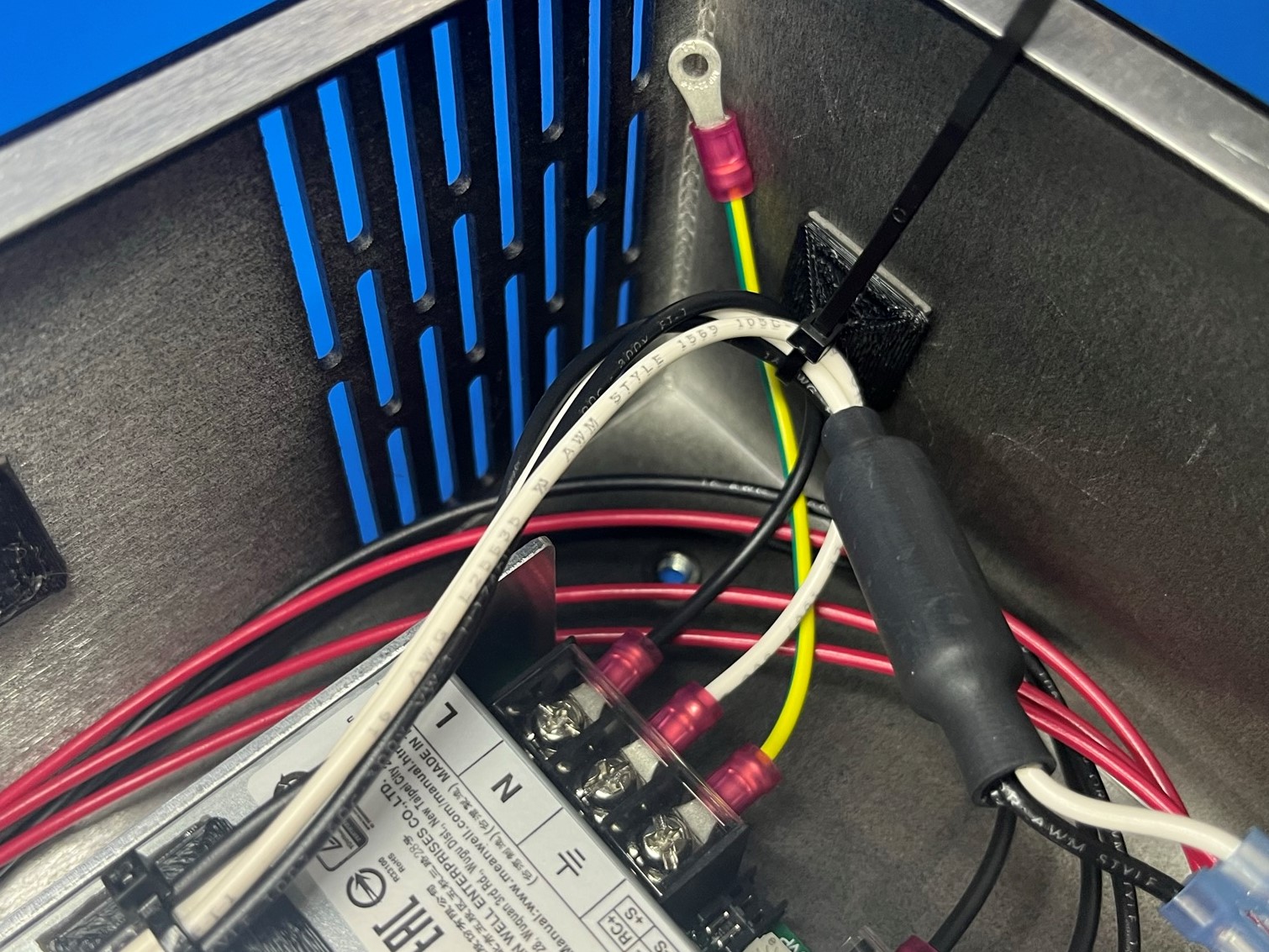
Slide the black wire under the terminal labeled “L”
Slide the white wire under the terminal labeled “N”
Once both wire are under the terminals tighten the terminal screws.
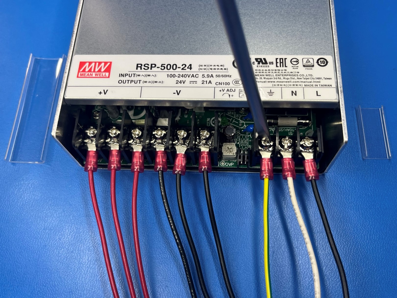
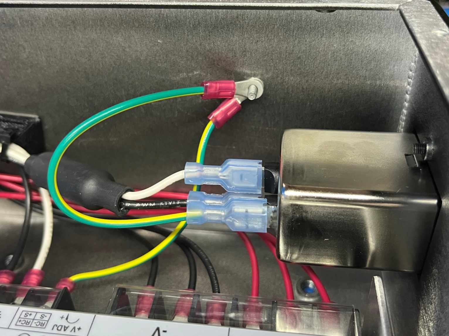
Then slide the PSU to ground green [EL-HR0152] to the power supply under the ground "⏚" terminal. Now tighten terminal screw to secure the harness.
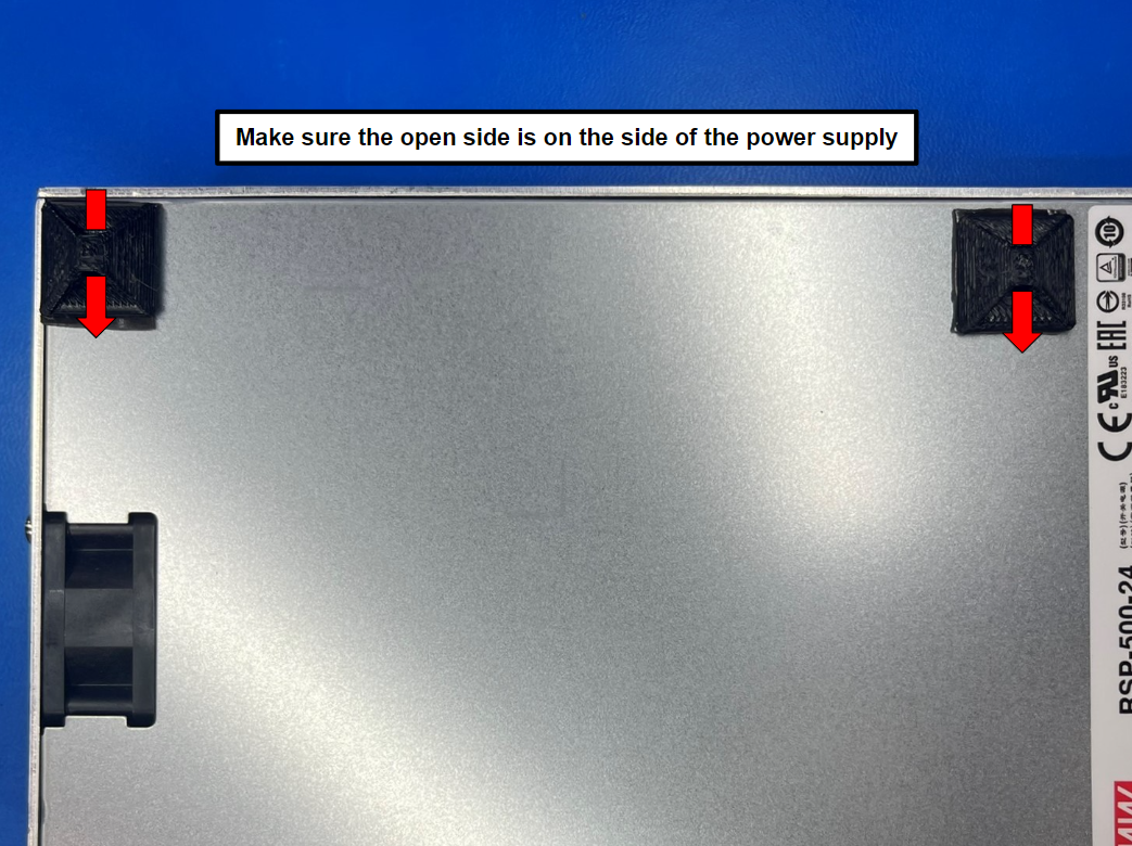
Remove one side of the protective covering on the adhesive square [HD-MS0571] and attach the adhesive to the universal cable tie holder [PP-GP0483]. Then remove the other side of the protective covering and place the cable tie holder to the power supply in the corner by the ⏚, L, N terminals.
Repeat for the second cable tie holder and place it on the same side in the top corner.

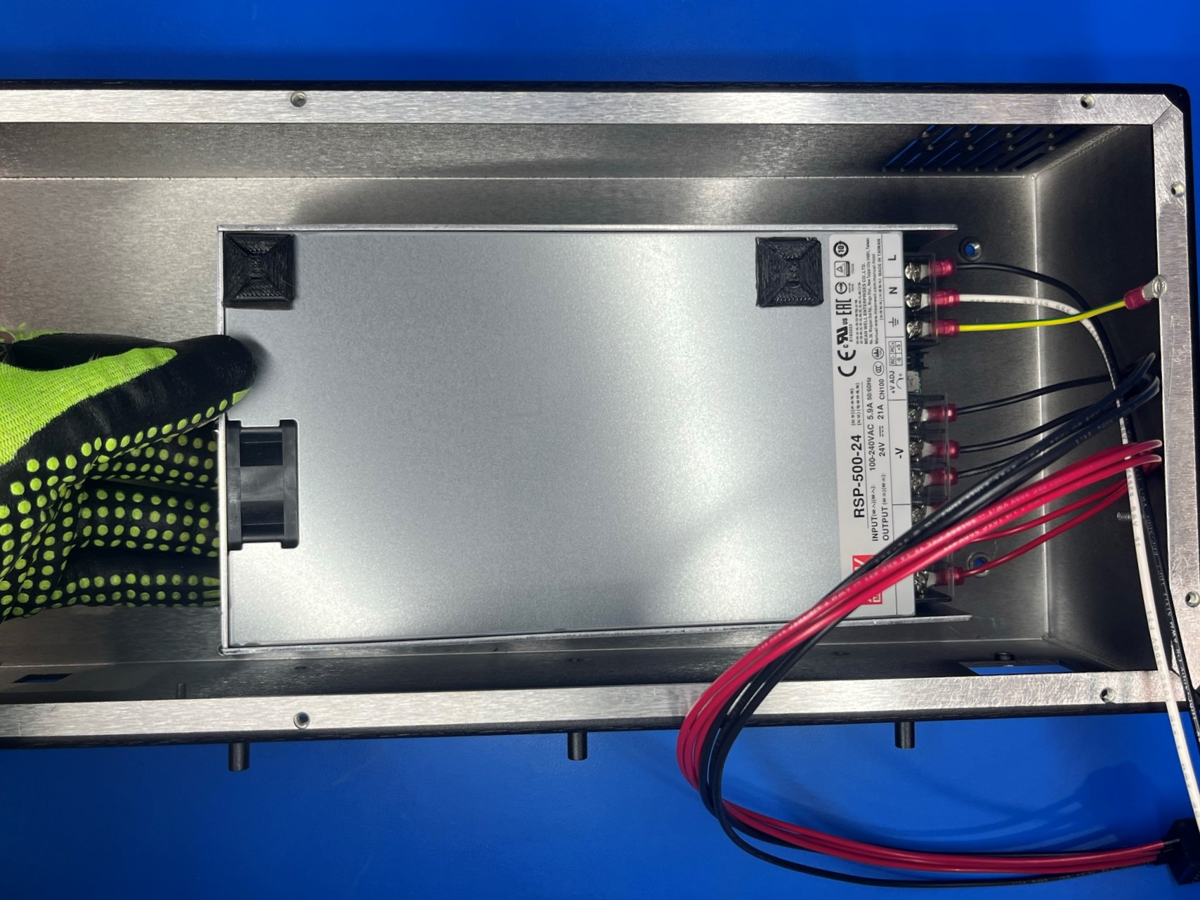
Place the power supply inside the electronics chassis [PP-FP0163] making sure the wires on the power supply are touching the bottom wall.
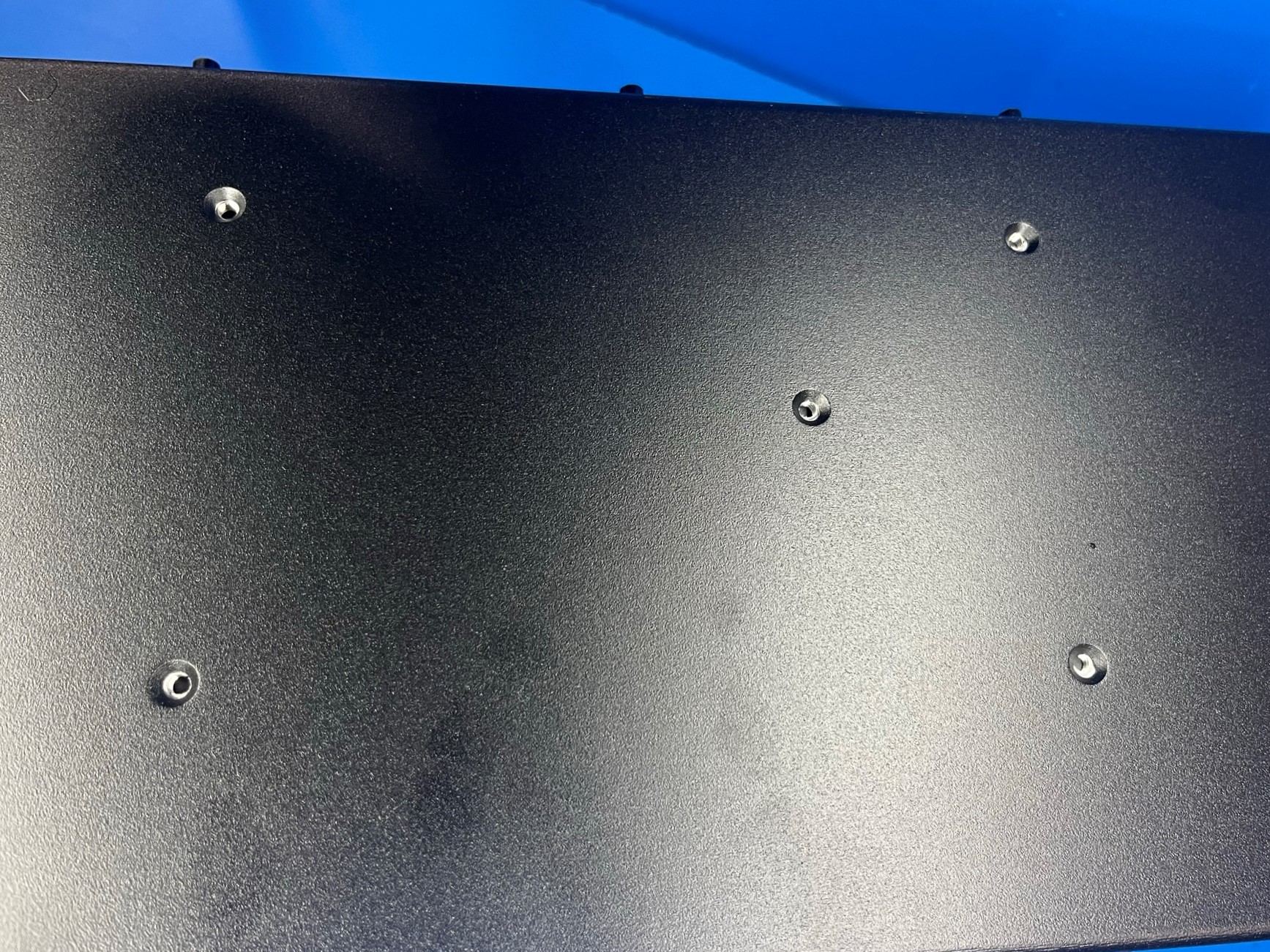
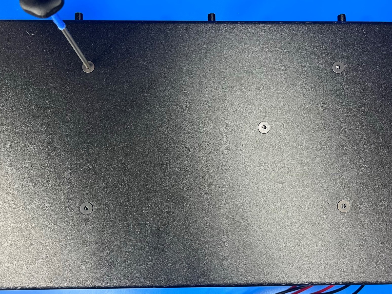
While holding the power supply inside the electronics chassis, flip both over and align the power supply with the five holes in the chassis. Once they are aligned secure the power supply with 5x M4x6 FHCS [HD-BT0155].
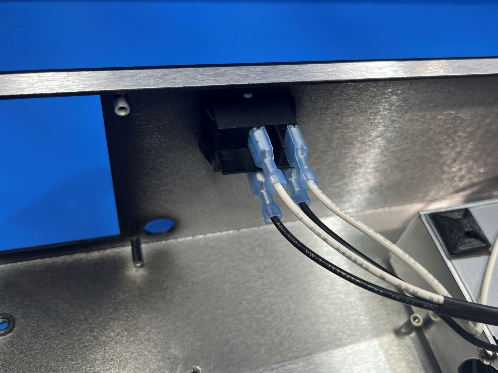
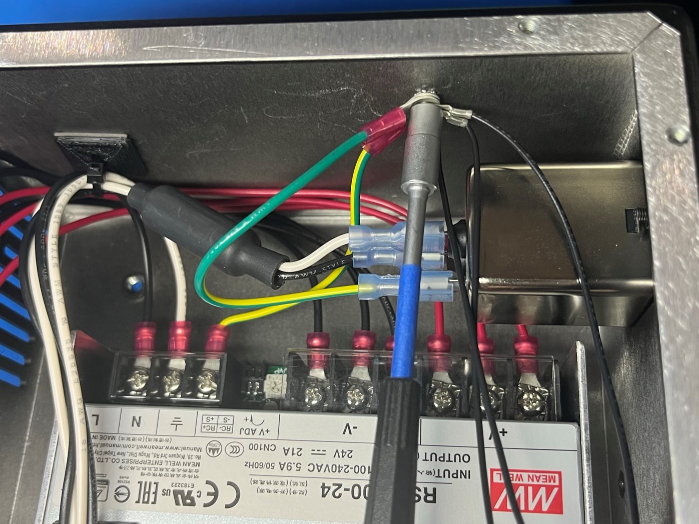
Then take the switch [EL-SW0023] and press it into the hole by the white on and off. Make sure the "I" on the switch is by the "ON".
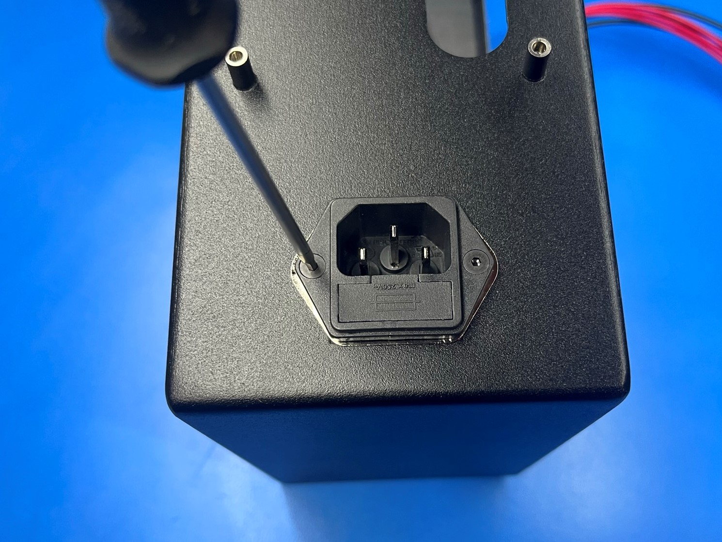
Now using 2x M3x10 FHCS [HD-BT0116] secure the power inlet [EL-MS0346] to the chassis making sure the fuse box is on the bottom.
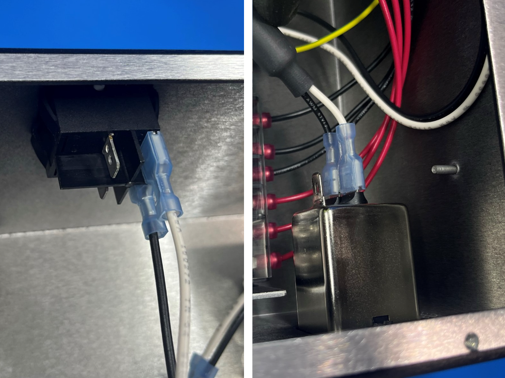
Then take the power to switch harness [EL-HR0168] and connect the side with the ferrite to the power inlet with white on top. Then take the other end and connect it to the bottom terminals on the switch with the white on top.
Then take the switch to PSU [EL-HR0157] and connect it to the top two terminals.
Place 1x universal cable tie holder [PP-GP0483] in the corner of the electronics chassis using 1x adhesive square [HD-MS0571].
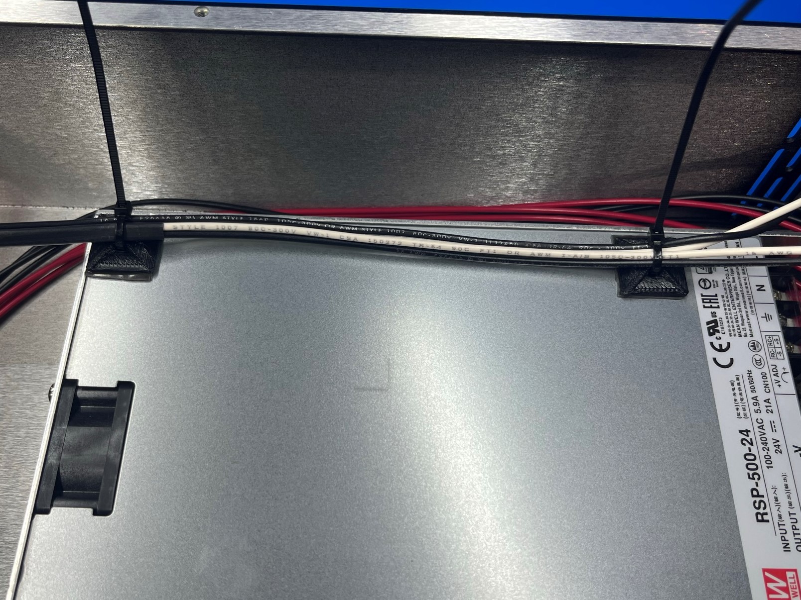
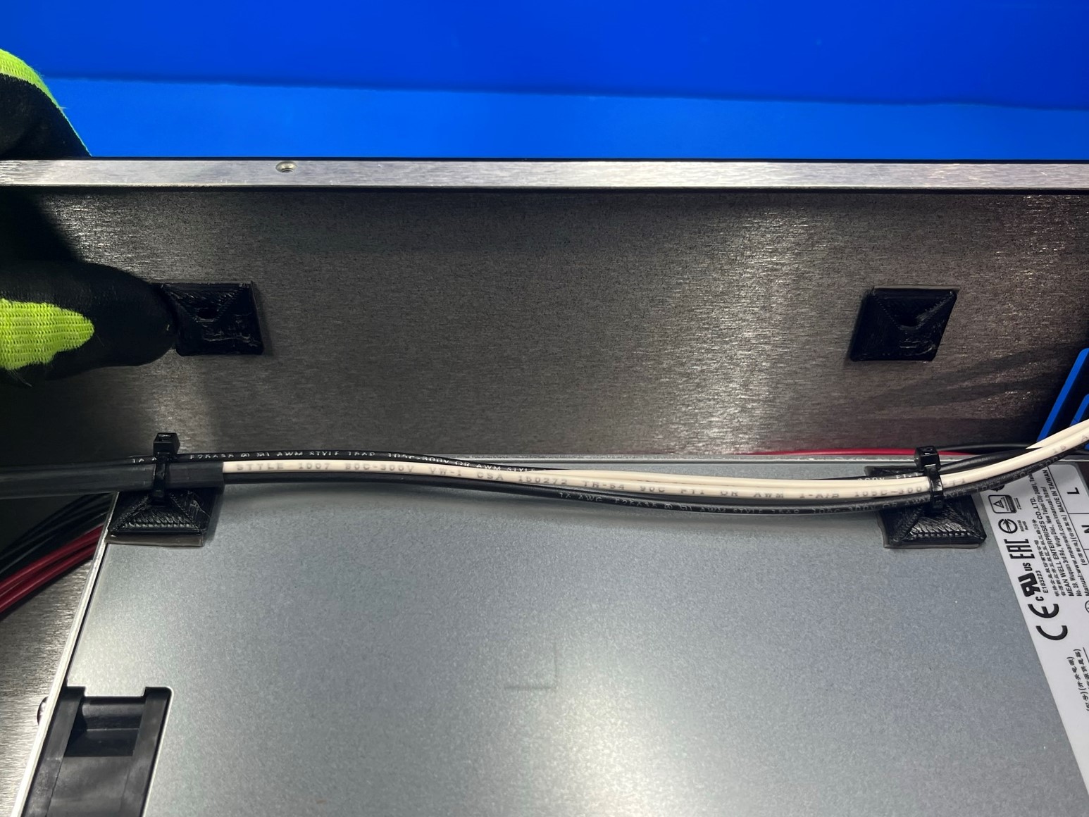
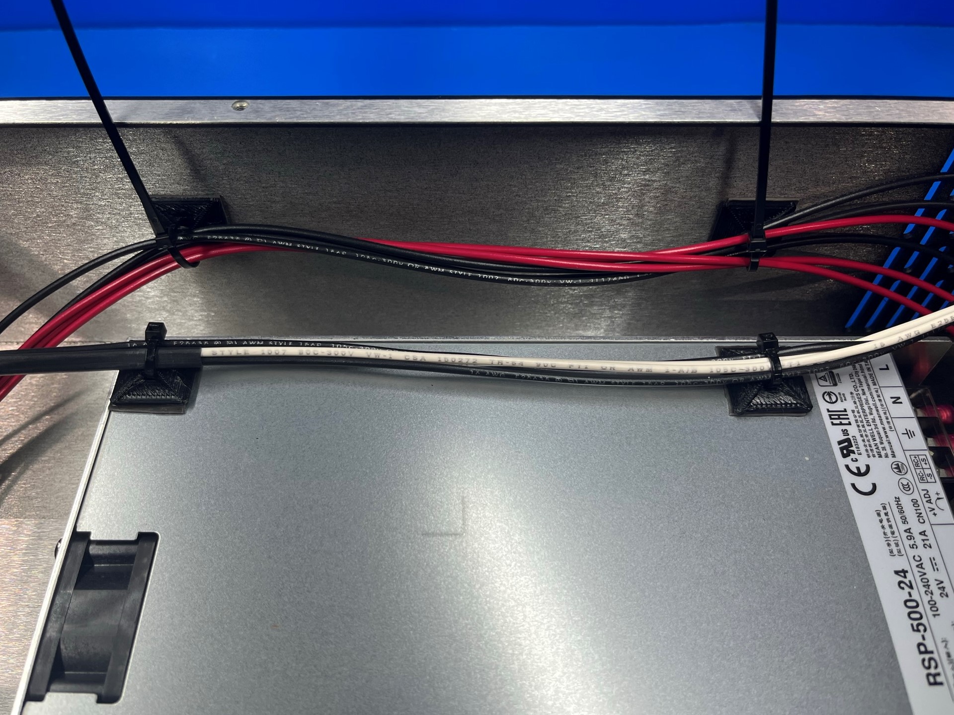
Then route the black and white wires over the two power supply universal cable tie holders and use 2x cable ties [HD-MS0058] to secure the wires to the power supply.
Repeat process for the cable tie holder in the corner.


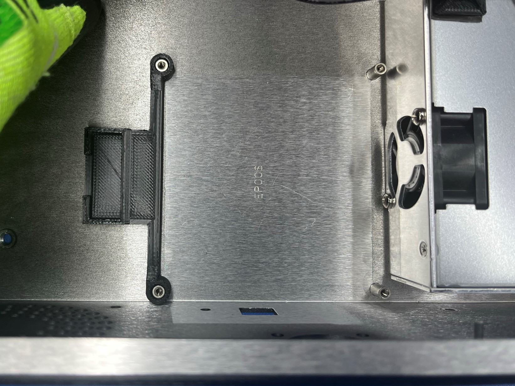
Place the 5A fuse mount [PP-GP0464] over the end board standoff so that the 5A holder is on the outside.
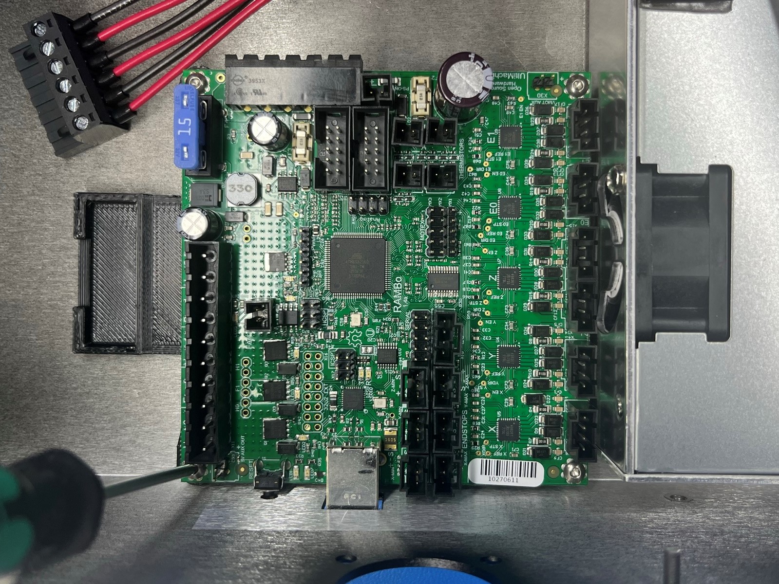
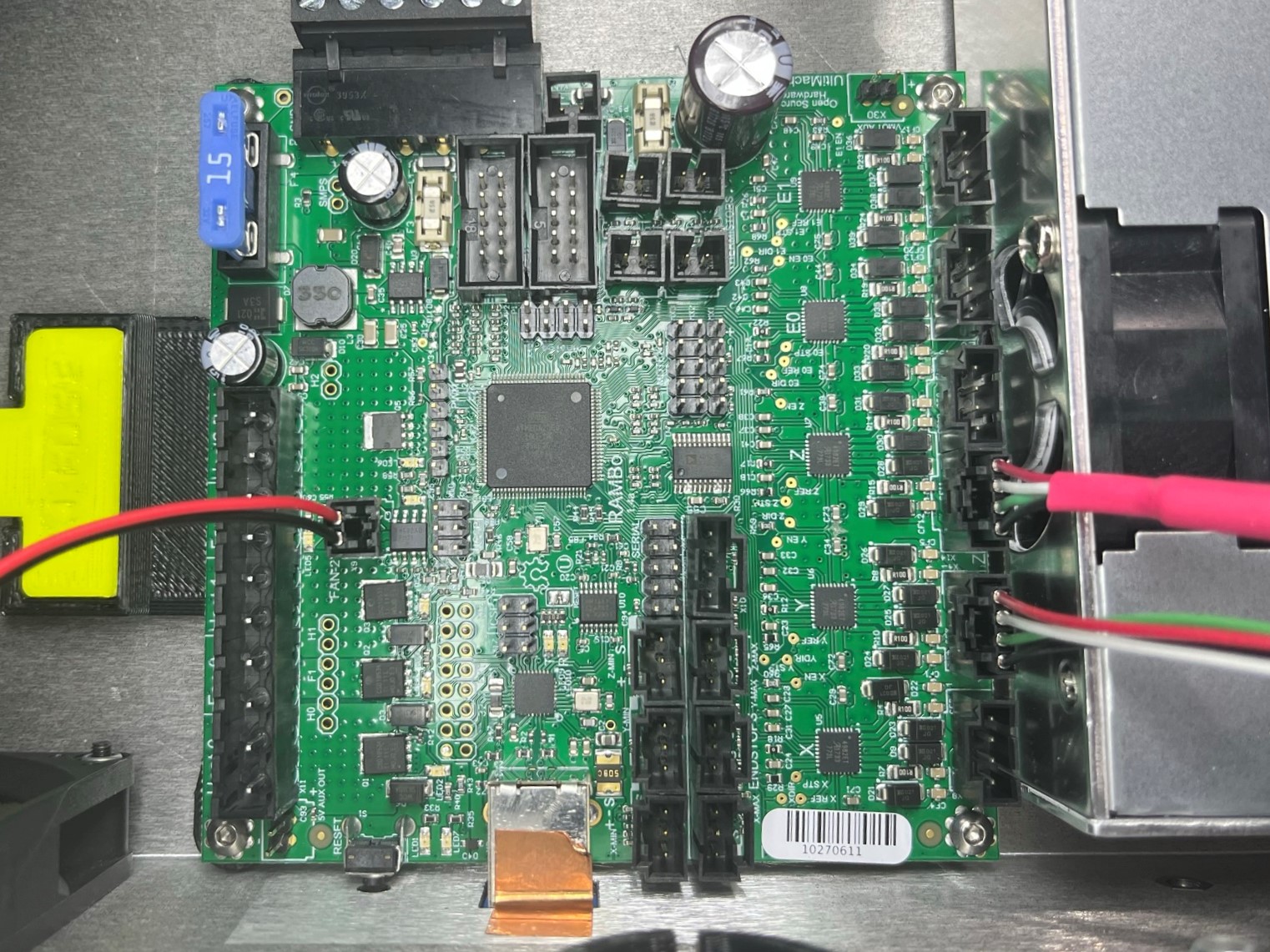
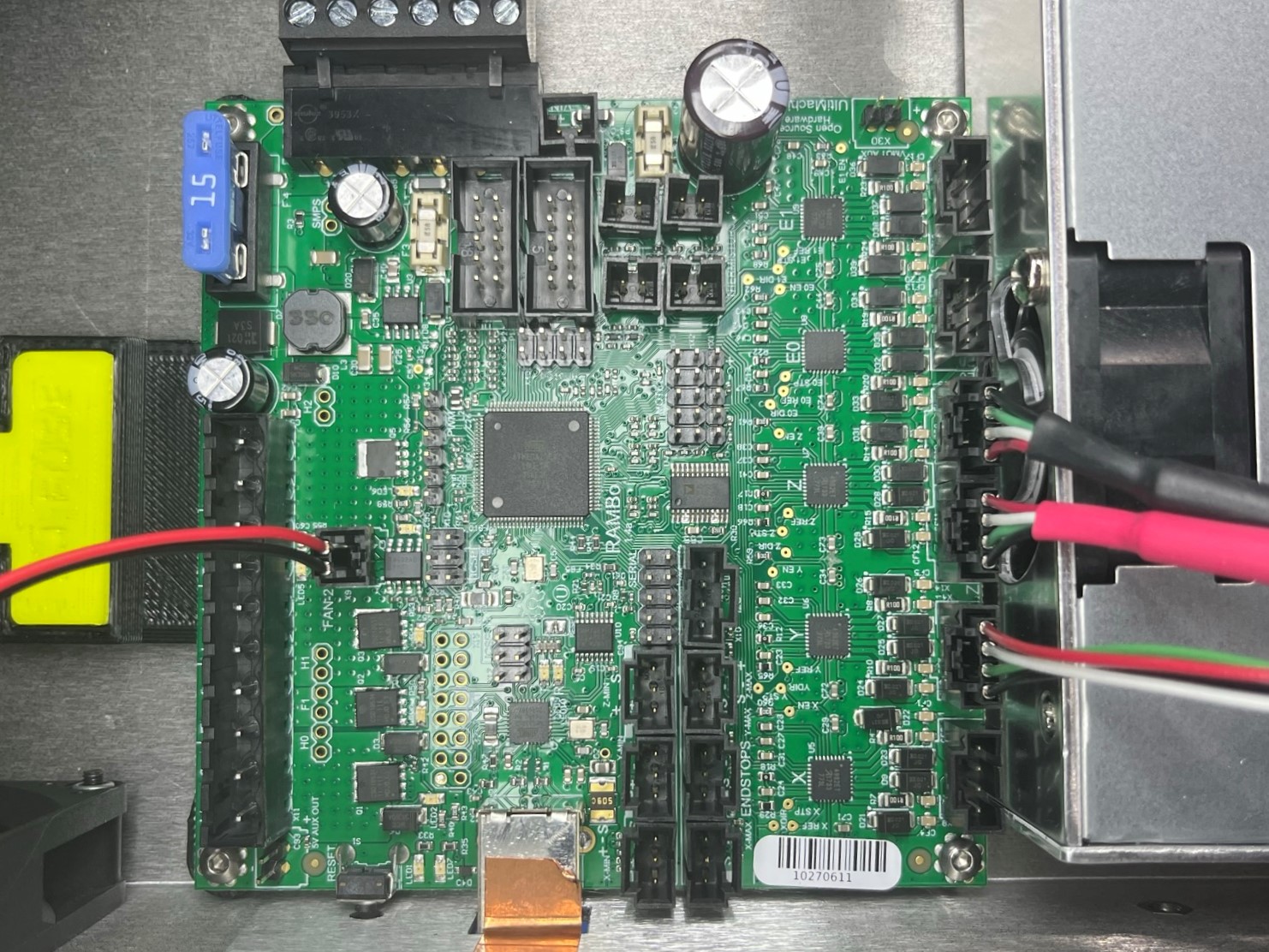
Then take the RAMBo electronics board [PC-BD0094] and place it over the four board standoffs making sure the USB port aligns with the USB cutout in the chassis.
Now secure the 5A fuse mount and RAMBo board to the chassis using 4x M3x8 BHCS [HD-BT0104].
Take the CB DC power harness thats connected to the power supply and connect it to the RAMBo board.
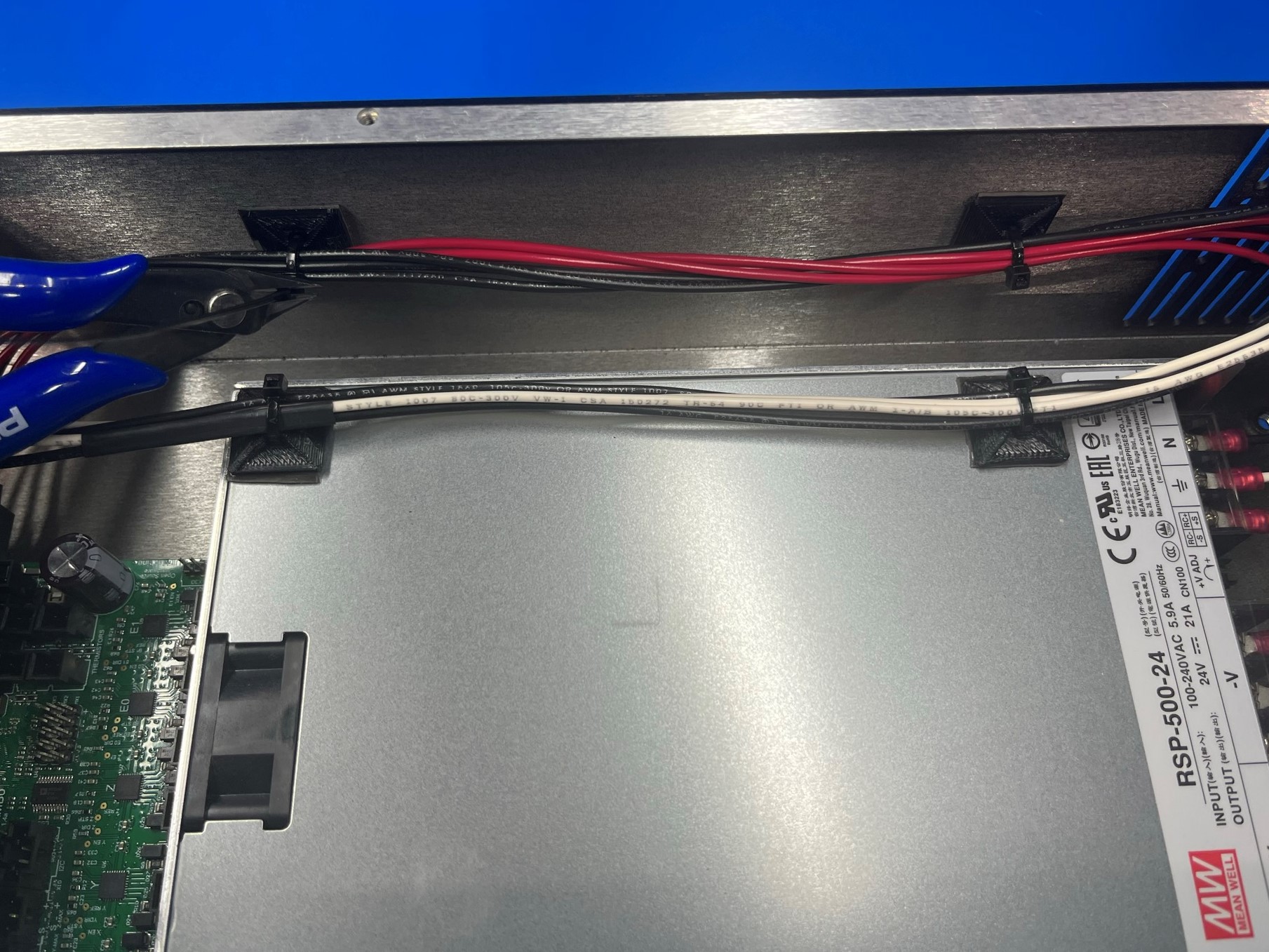
Repeating the process of placing universal cable tie holders, place 2x cable tie holders on the wall of the chassis by the two that are on the power supply.
Then secure the harness using 2x cable ties [HD-MS0058] and the 2x cable tie holders attached to the power supply.
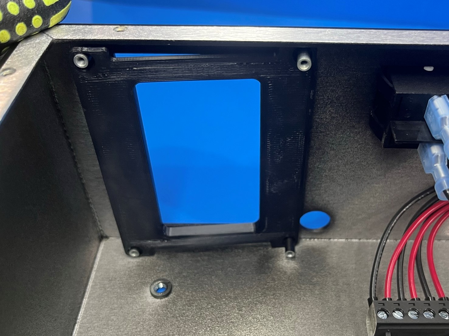
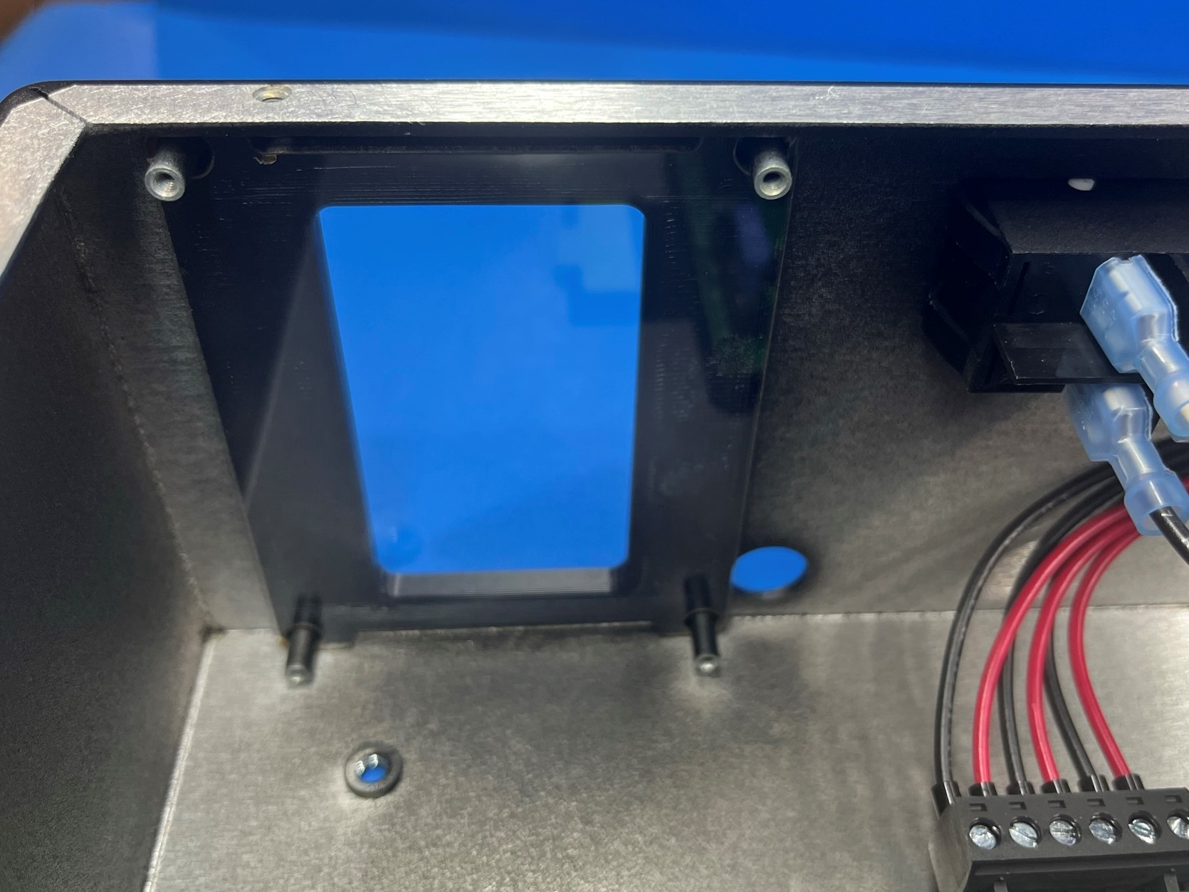
Slide the LCD bezel [PP-GP0230] over the four LCD standoffs. Make sure the flat side is on the inside of the chassis.
Then take the plastic laser cut LCD cover [PC-AS0041] and remove the protective cover from both sides. Make sure not to scratch the plastic while removing the covering.
Now slide the LCD cover over the four LCD standoffs.
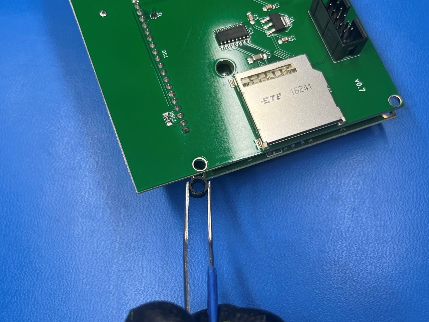
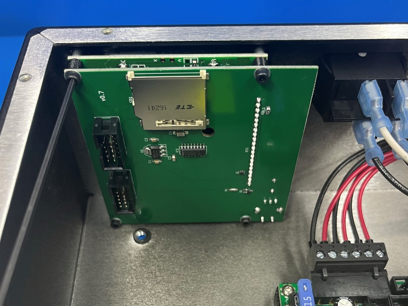
Prepare the LCD LB_gLCD [PC-AS0056] by placing a LCD spacer [PP-GP0089] between the two circuit boards. Secure the LCD spacer using a M2.5x12 SHCS [HD-BT0054] with a M2.5 washer [HD-WA0013].
Repeat for the other holes using 3x LCD spacers, M2.5x12 SHCS, and M2.5 washers.
Then carefully align the LCD with the four LCD standoffs making sure the dial is on the bottom. Make sure none of the LCD spacers fall out and secure to the LCD to the chassis.
Flip the chassis on its side if the LCD spacers keep falling out.
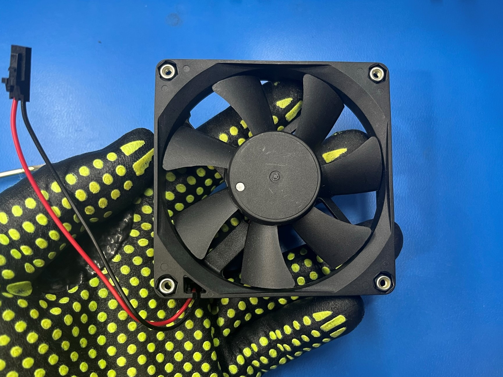
Take the CB case fan [EL-FA0061] and place 4x M3 lock nuts [HD-NT0001] inside the four nut traps. Make sure the nylon ring is on the outside.
Then carefully align the case fan with the four holes in the chassis. Make sure the side with the sticker is against the chassis and the wires are closest to the rambo board.
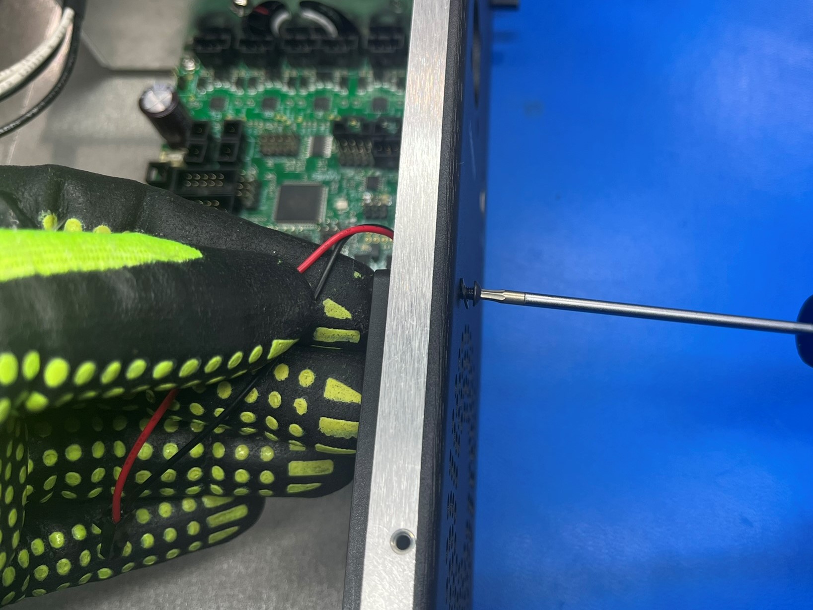
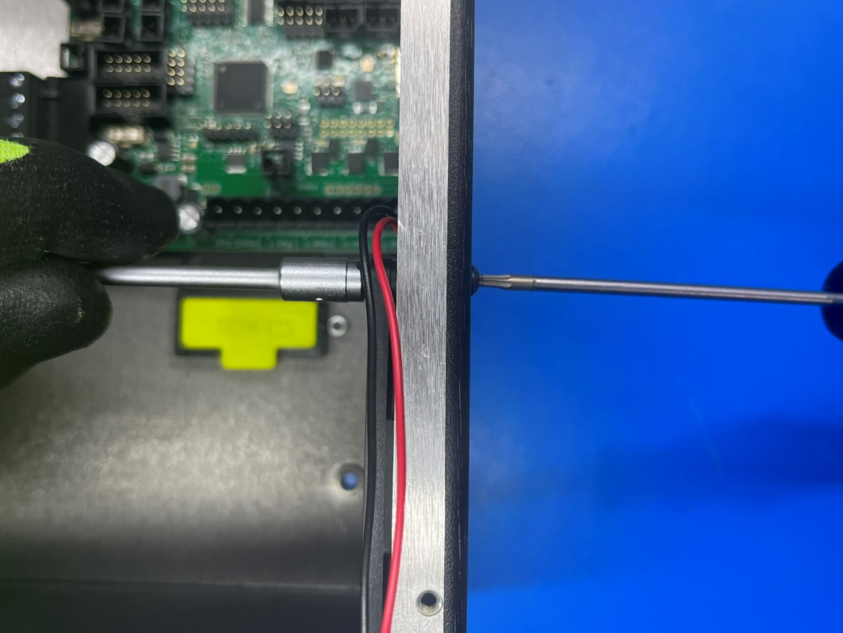
Then secure the case fan to the chassis using 4x M3x20 BHCS [HD-BT0171] with M3 washers [HD-WA0038]. If the M3 lock nut spins inside the nut trap use the cut nut driver to hold the nut in place.


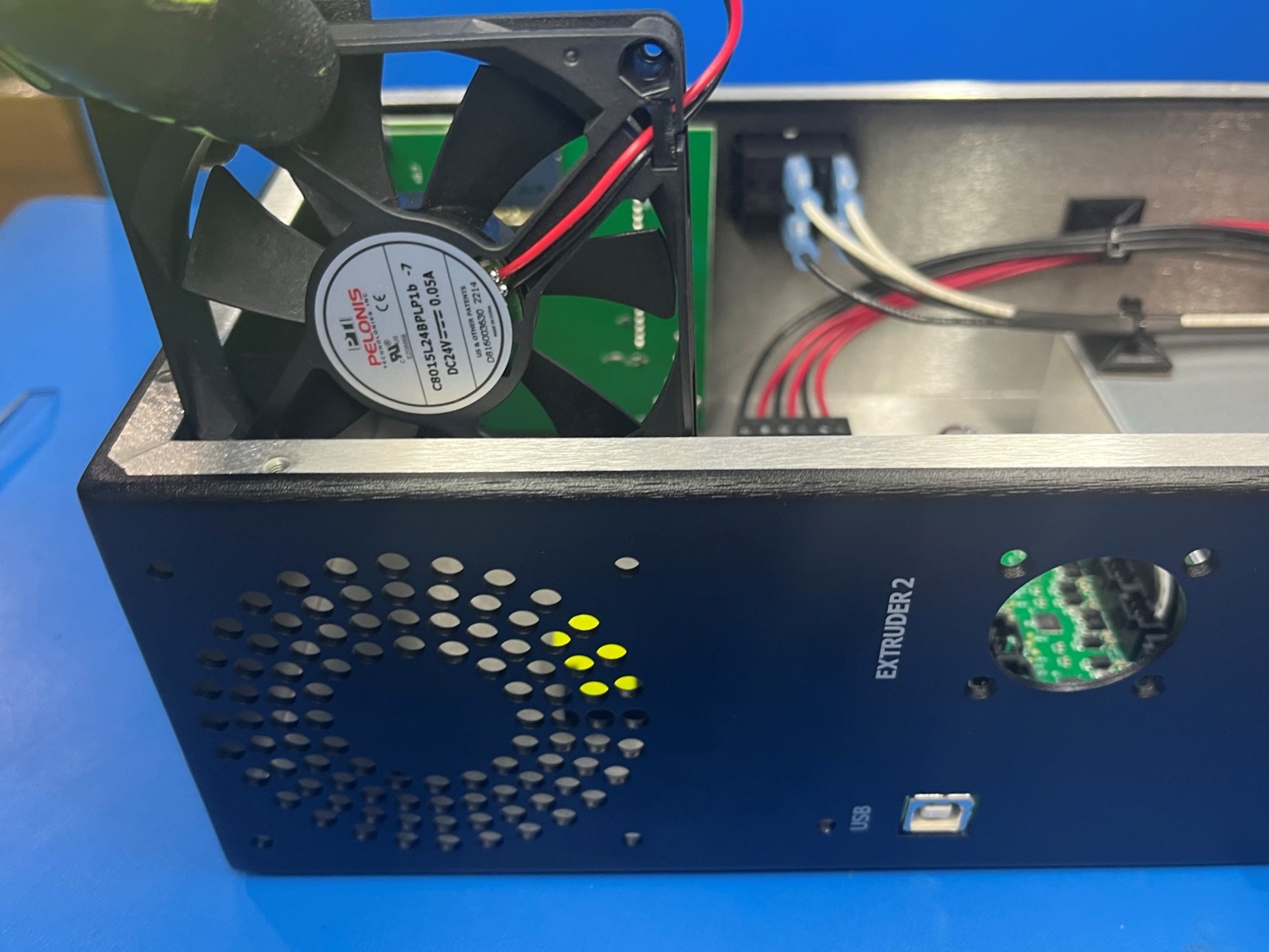
Then take the case fan harness and connect it to the RAMBo board in the single port on the topside. Make sure the harness clicks when you connect it to ensure the locking tab is in place.
Now take the adhesive copper foil [EL-MS0560] and connect the USB port to the chassis. The copper foil should be halfway on the USB port and halfway on the chassis.
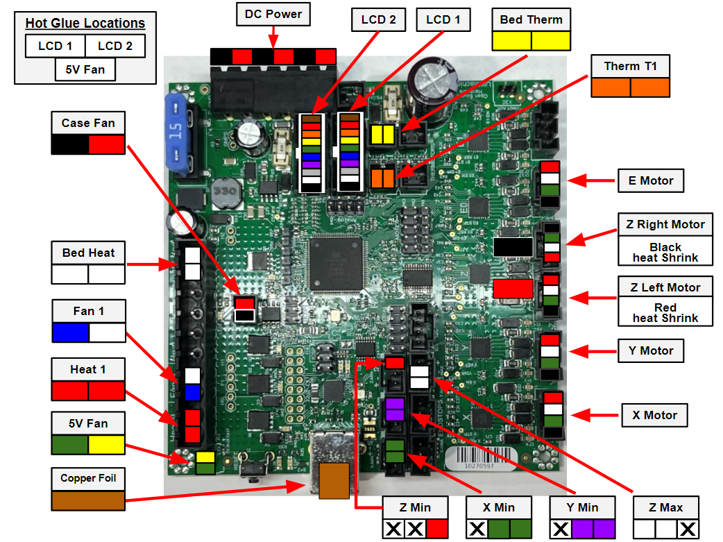

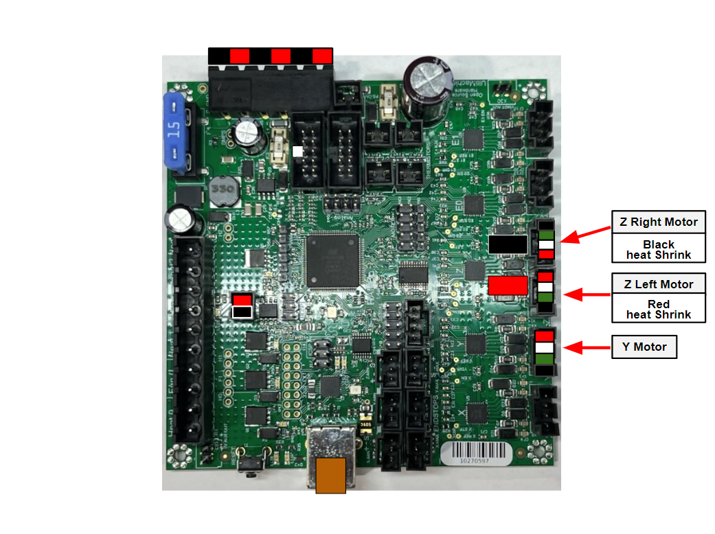
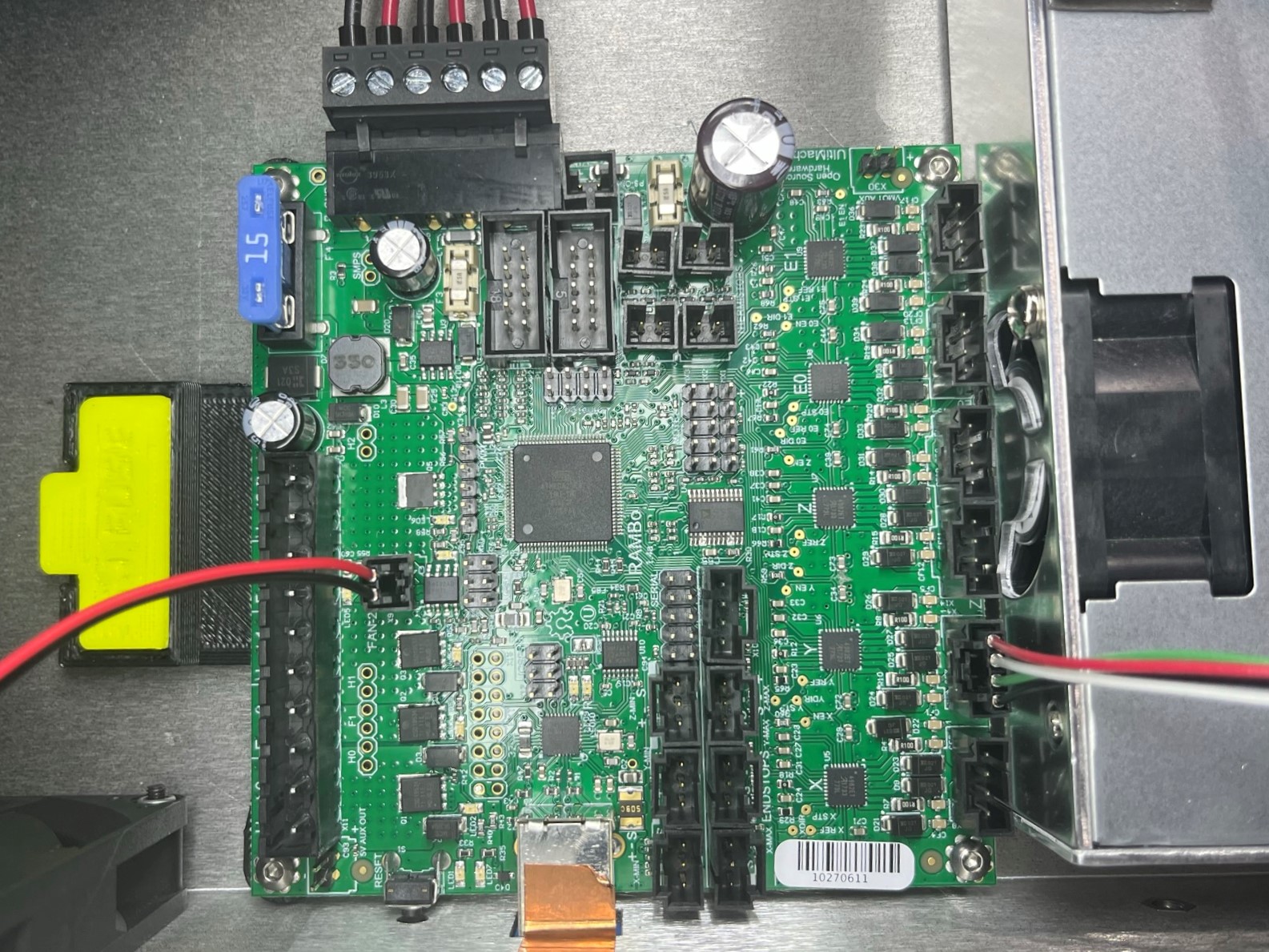
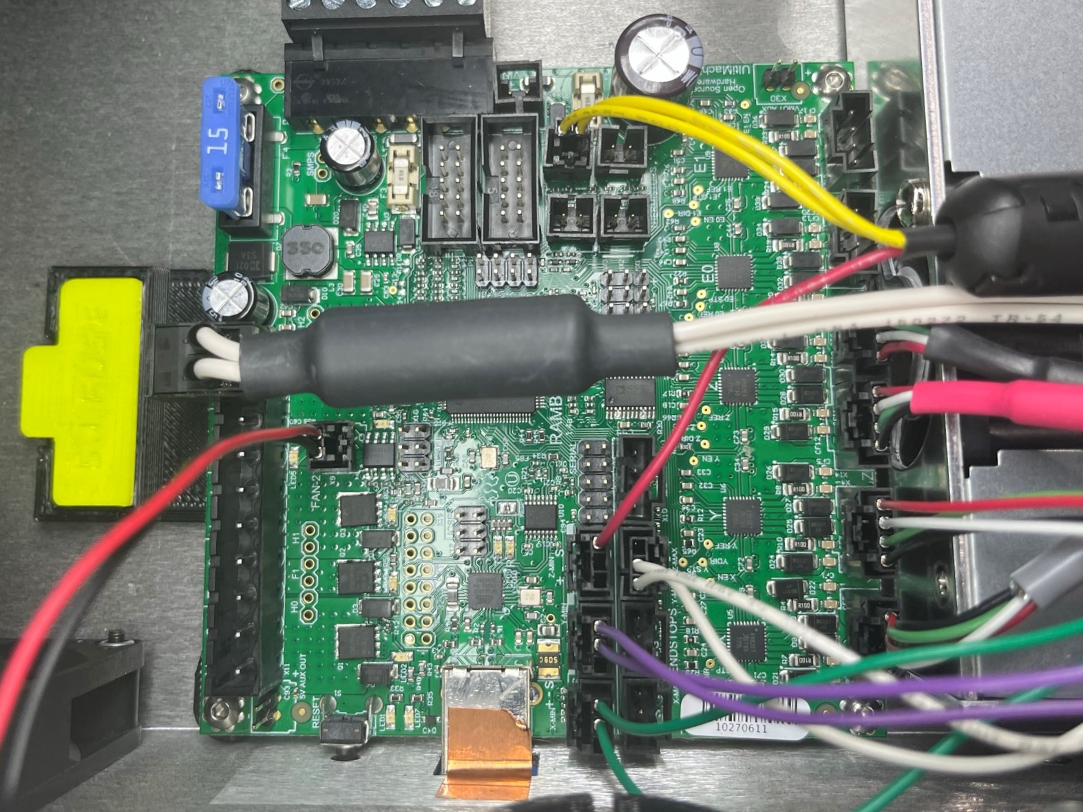
Take the CB YZ harness [EL-HR0183] and connect the bare motor harness to the second motor port (Y Motor).
Then repeat the process for the left and right motor harnesses.
The harness with the red heat shrink will go in the third motor port (Z left Motor) and the harness with the black heat shrink will go in the fourth motor port (Z Right Motor).
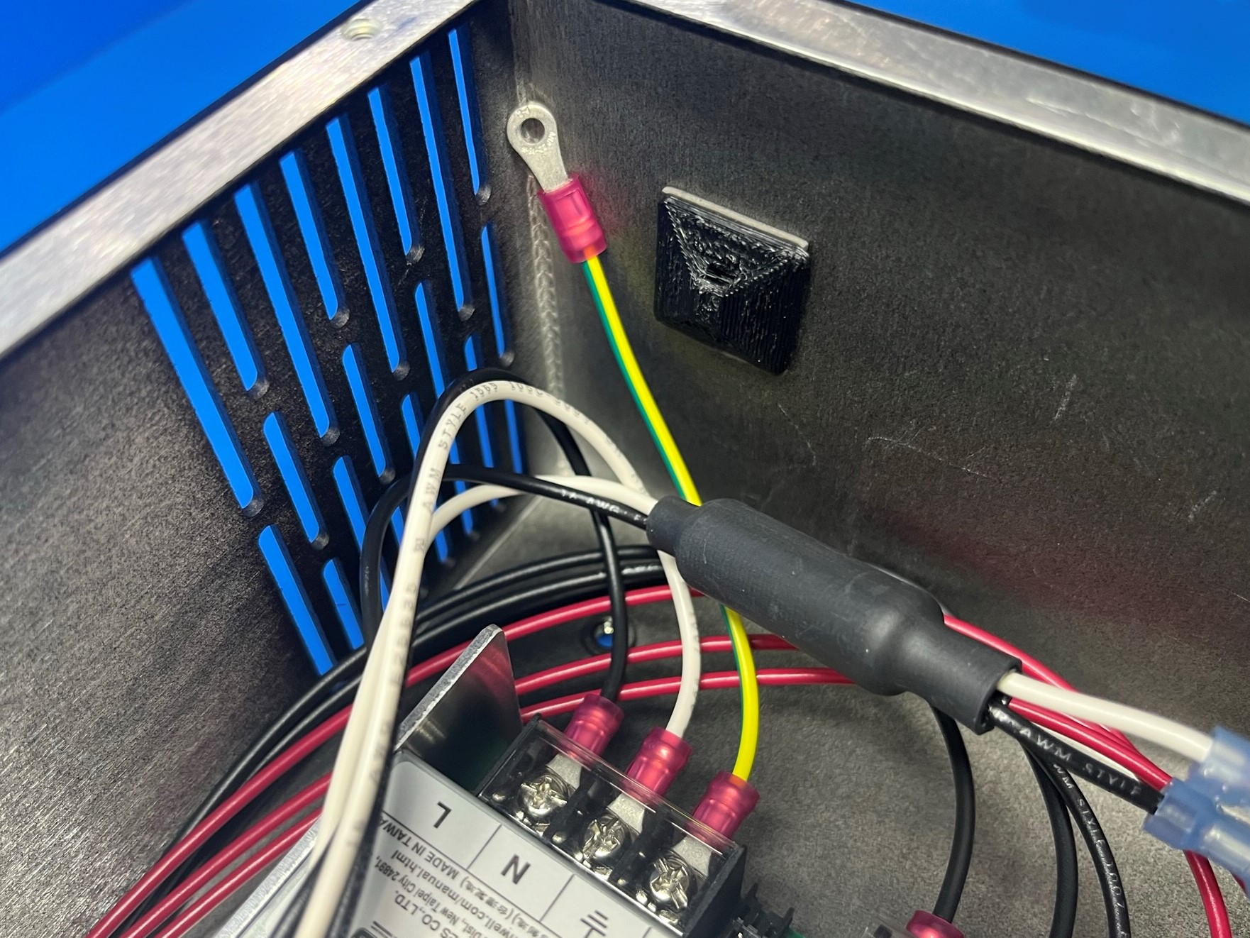
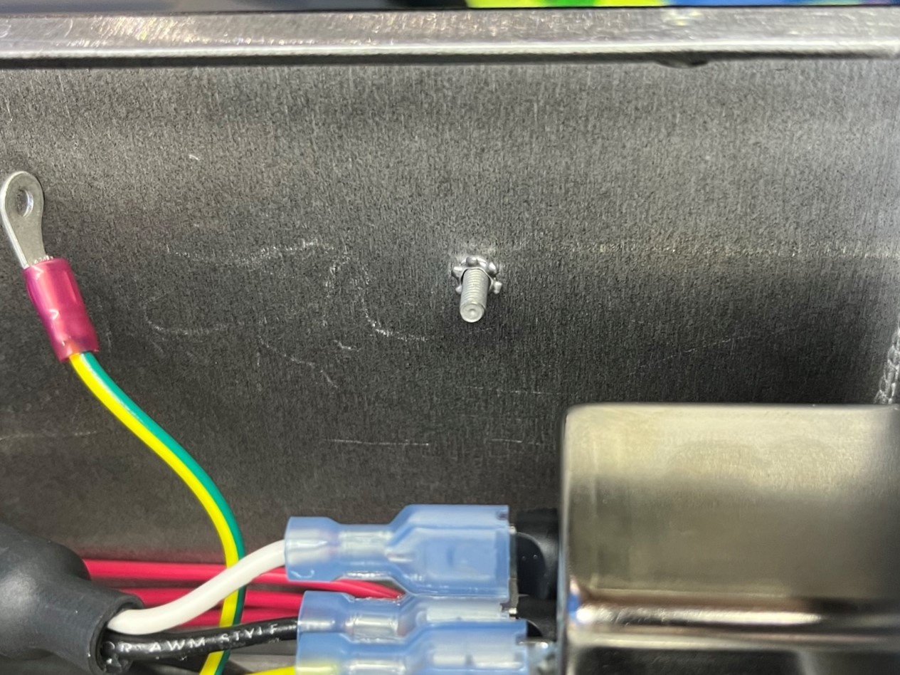
Place a lock washer [HD-WA0035] around the ground post near the power supply and power inlet then take the green ground wire attached to the power supply [EL-HR0152] around the ground post.
Connect the plug to ground green wire [EL-HR0167] to the top tab on the power inlet then take the other end and place it around the ground post.
Find the three black ground wires connected to the YZ harness [EL-HR0183] and place them around the ground post.
Once all the harnesses are placed around the ground post secure them using 1x M3 lock nut [HD-NT0001].
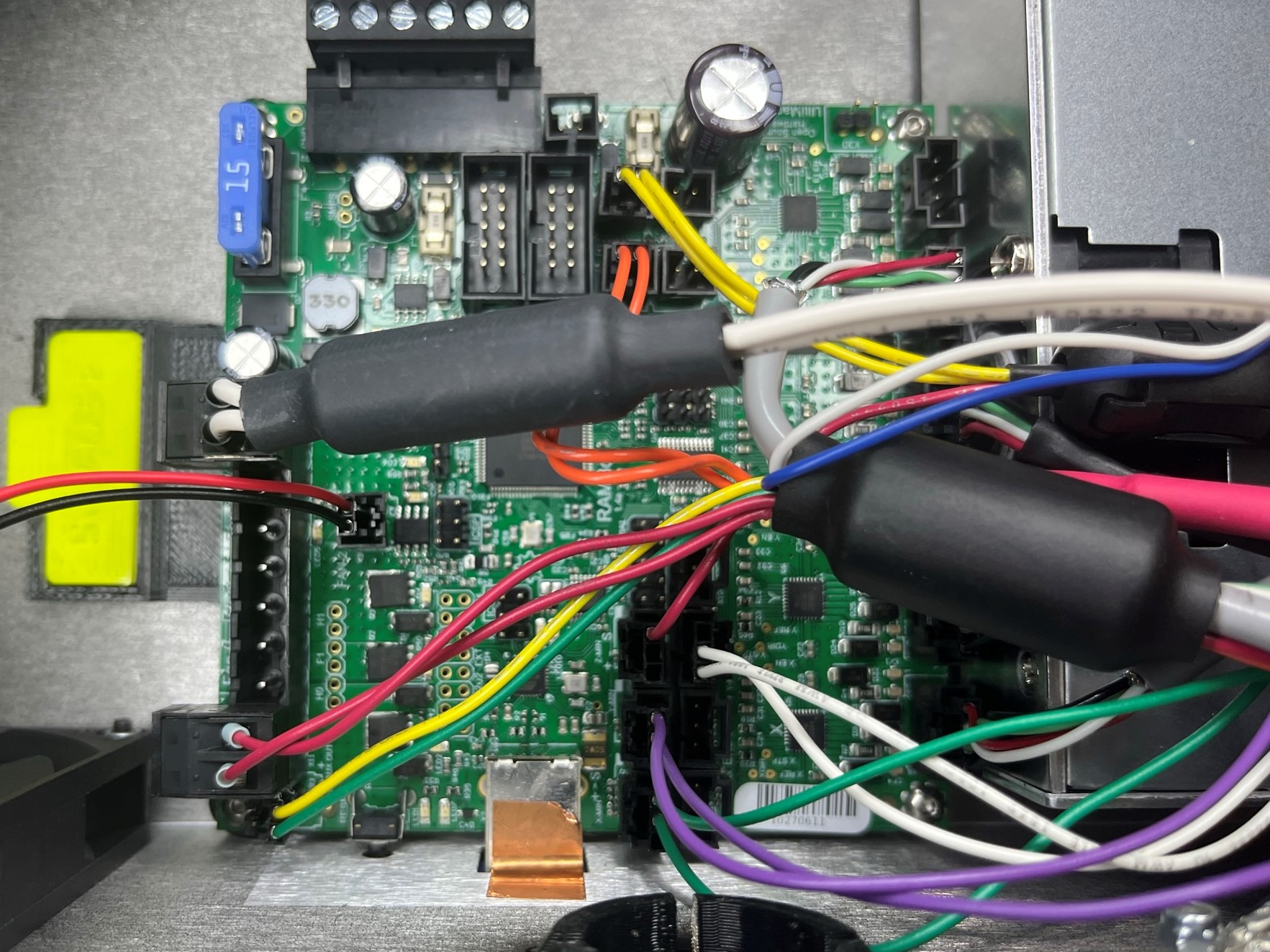
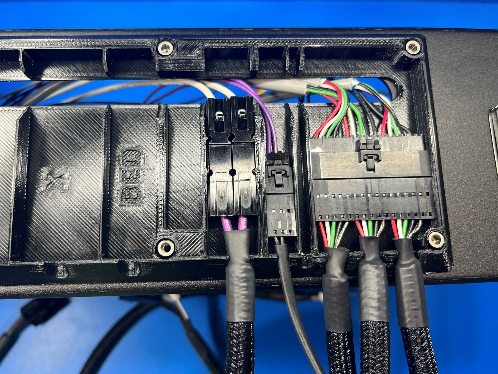
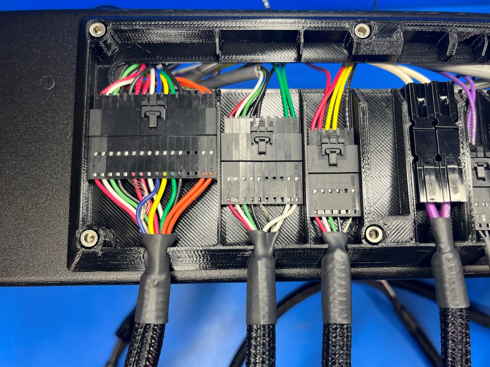
Take the CB Z endstop harness [EL-HR0185] and connect it to the board.
Now take the CB bed harness [EL-HR0184] and find the Z min wire (RED) and connect it to the board.
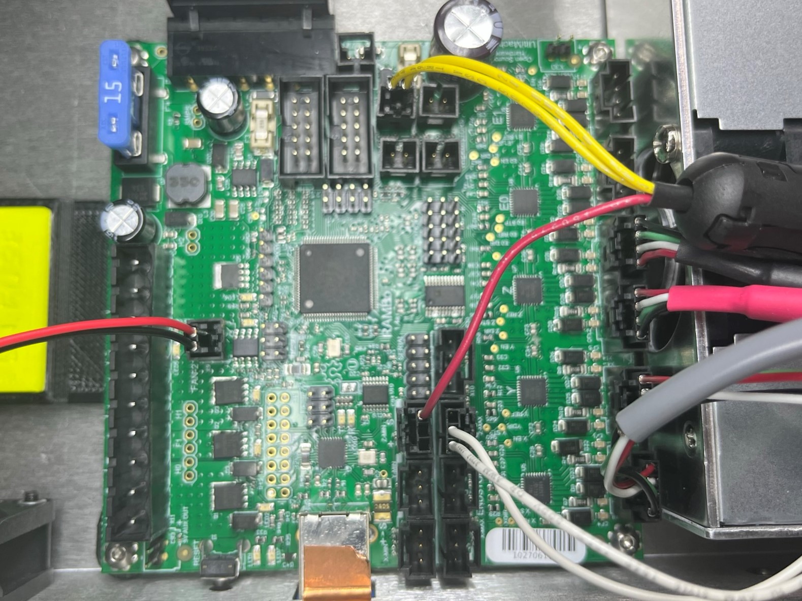
Then take the bed therm wire (YELLOW) and connect it to the board.
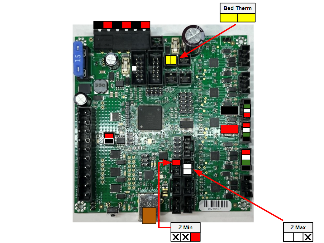
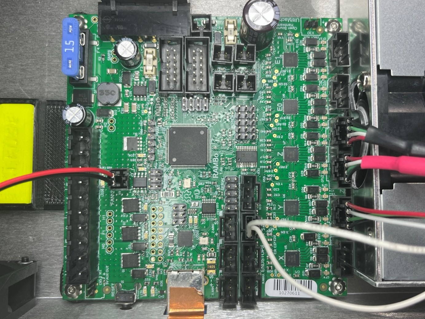
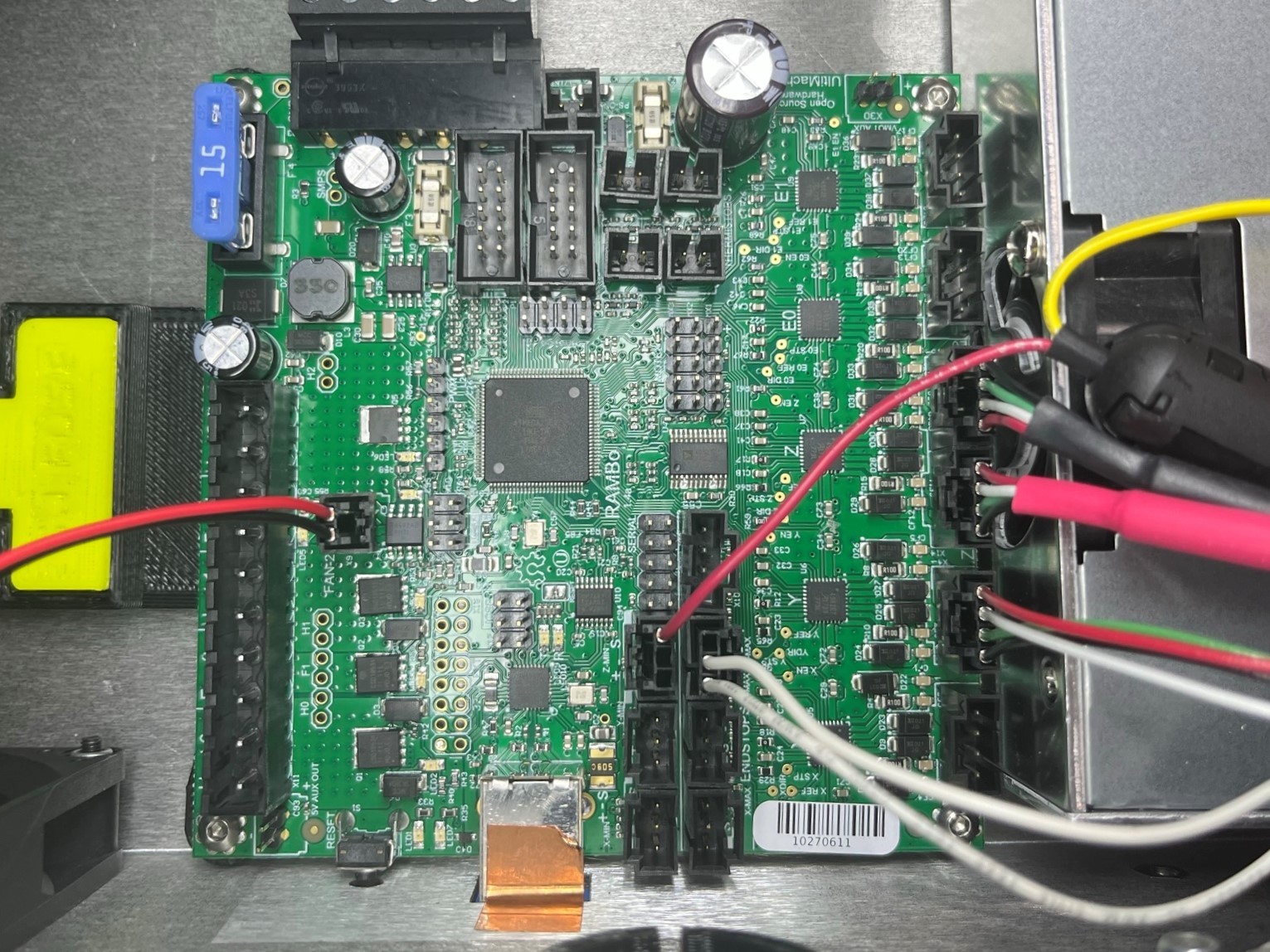

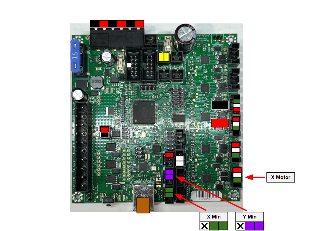
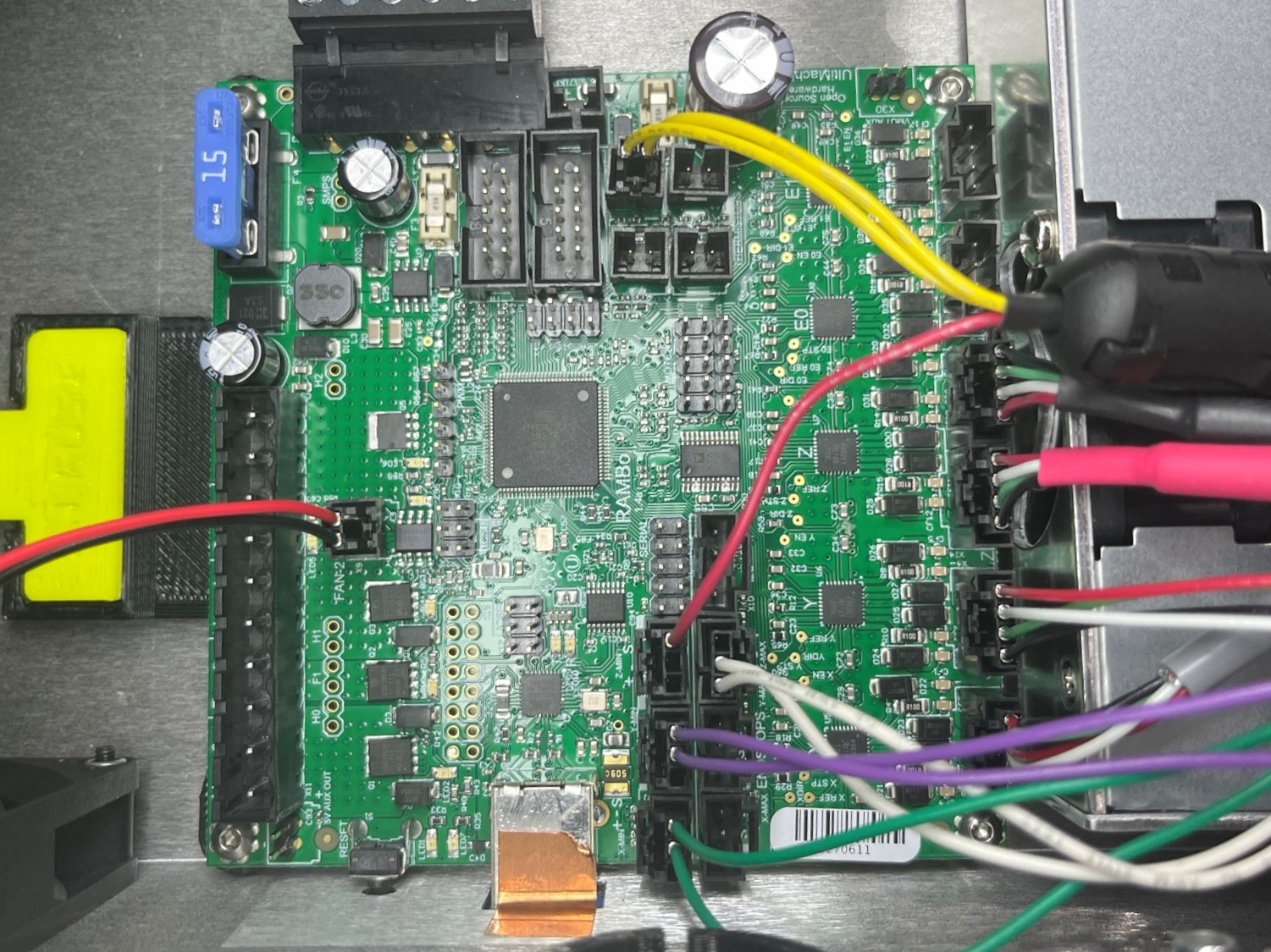
Take the CB X harness [EL-HR0173] and connect the X motor wire to the board.
Then take the X min wire (GREEN) and connect it to the board.
Repeat for the [EL-HR0177] Y min wire (PURPLE)
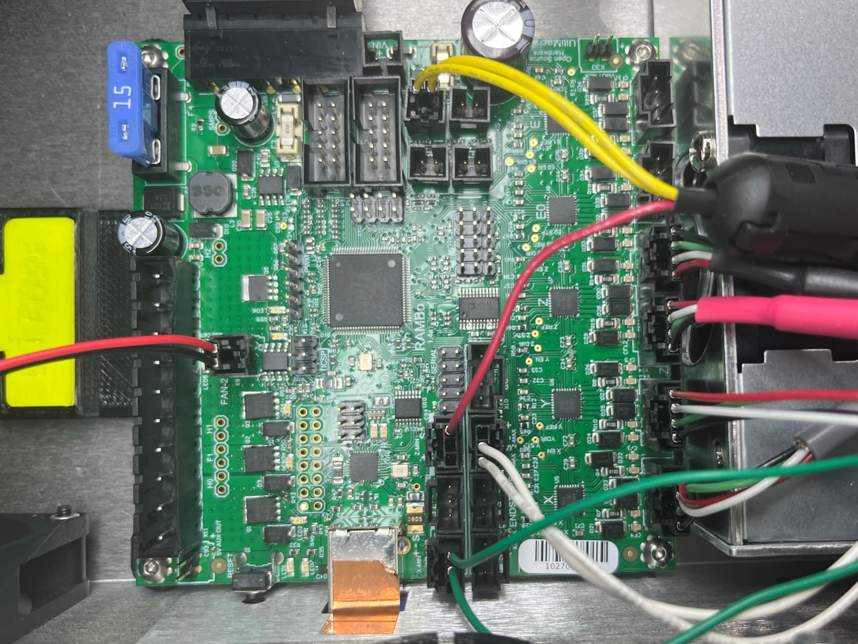
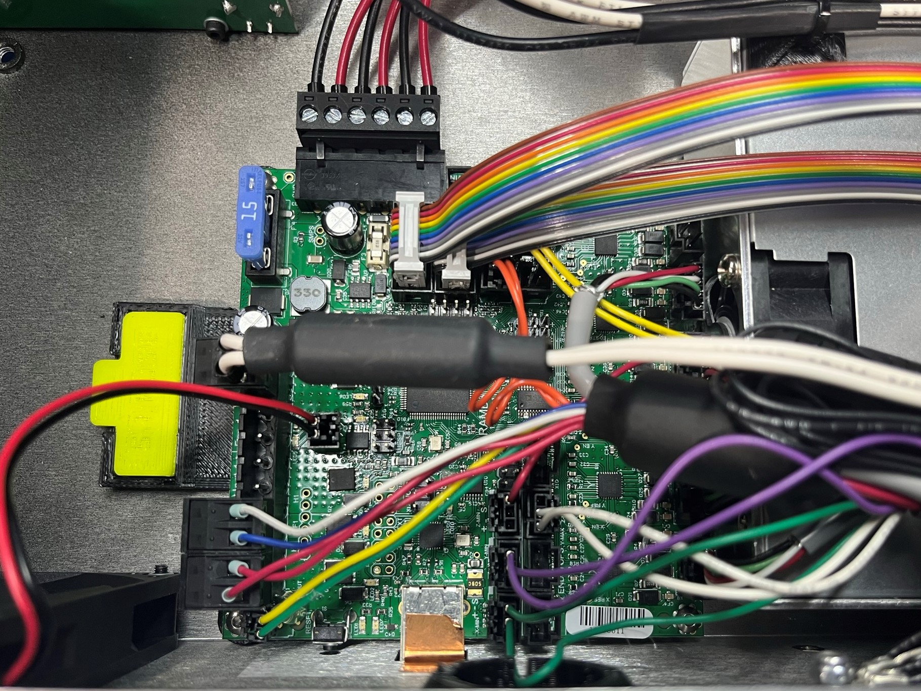
Take the TAZ Pro/WE, CB bed power harness [EL-HR0148] and connect it to the board in the last block connector slot. (By the CB BLUE fuse)
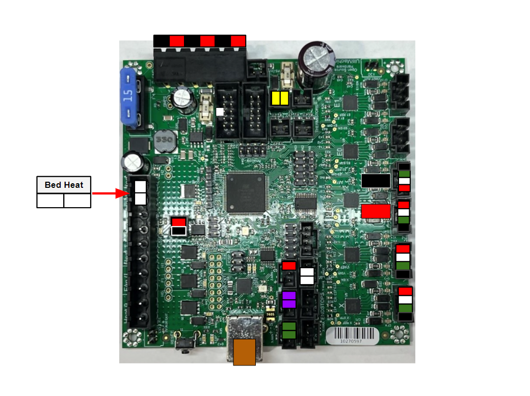
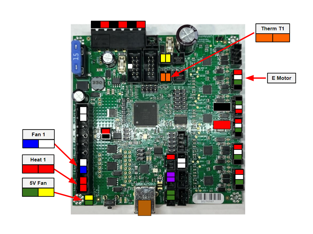
Take the E motor harness that's connected to the CB extruder harness [EL-HR0175] and connect it to the board next to the right Z motor.
Find the therm T1 wire (ORANGE) and connect it to the board by the bed therm wire.
Then find the 5V fan wire (GREEN and YELLOW) and connect it to the two bare pins at the end of the block connector ports.
Now take the Heat 1 wire (RED) and connect it to the last block connector port.
Find the fan 1 wire (BLUE and WHITE) and connect it next to the heat 1 wire.


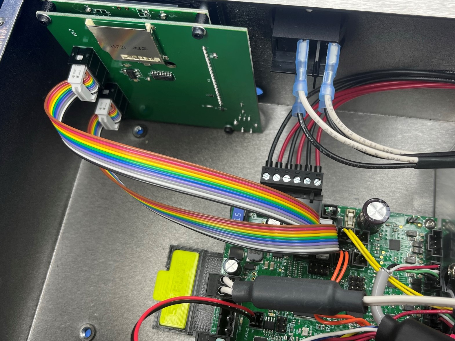
Take 1x LCD-USB harness [EL-HR0147] and connect it in the right LCD port on the board. Make sure the wires are on the opposite side of the tabs.
Then repeat the process for the other LCD port with 1x LCD-USB harness. Make sure the wires are on the opposite side of the tabs.
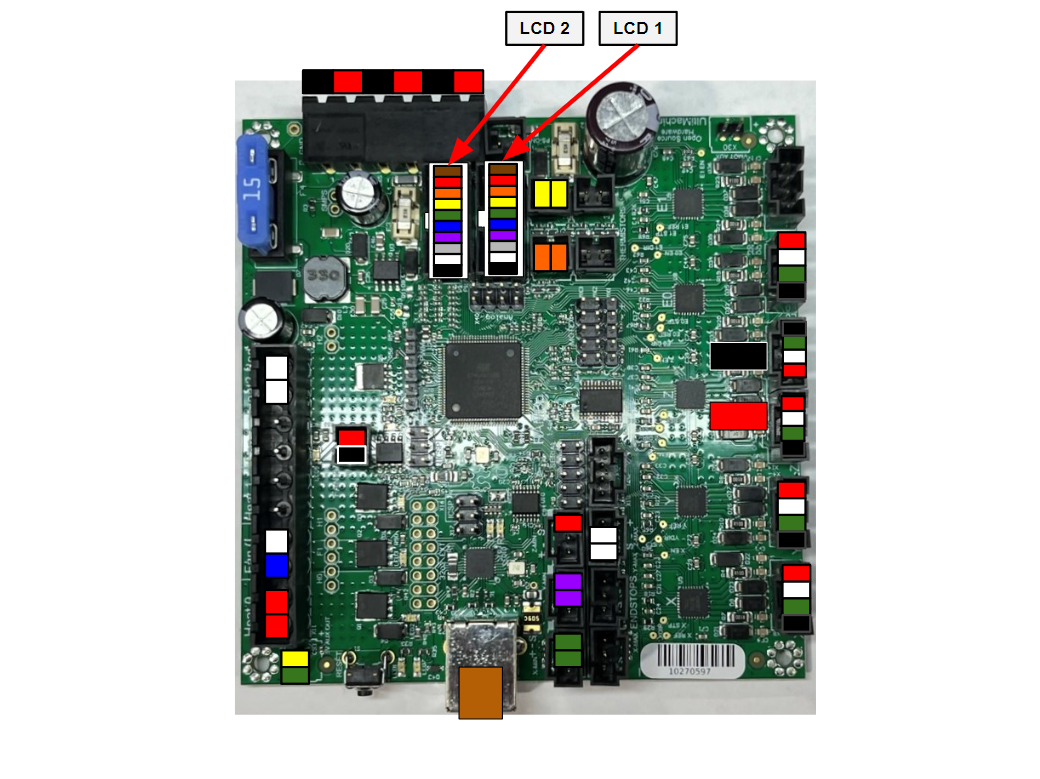

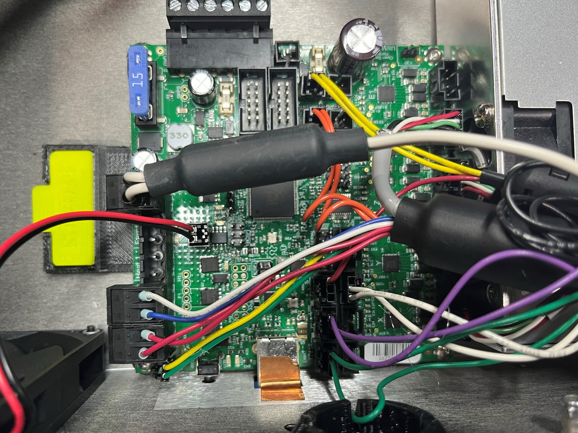
Take the second LCD harness LCD 2 and connect it to the top port on the LCD EXP 2.
Repeat for the first LCD harness LCD 1 and port EXP 1 make sure both LCD are bending as shown in the pictures.
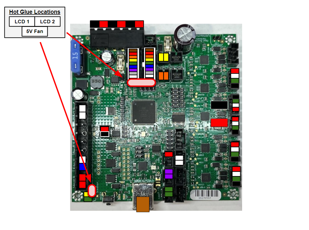
Now take the hot glue gun and glue the two LCD connectors into the LCD ports. This ensures a solid connection.
Then glue the 5V fan into place. This is needed since there isn't a male connector housing for this wire.


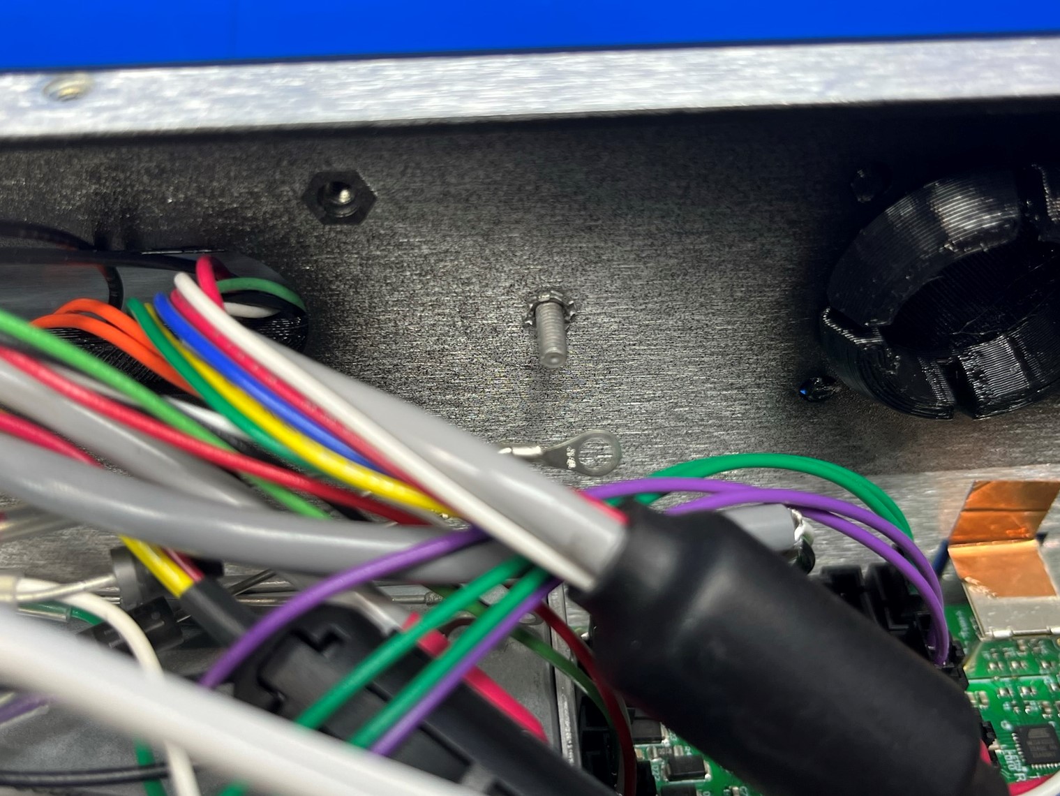
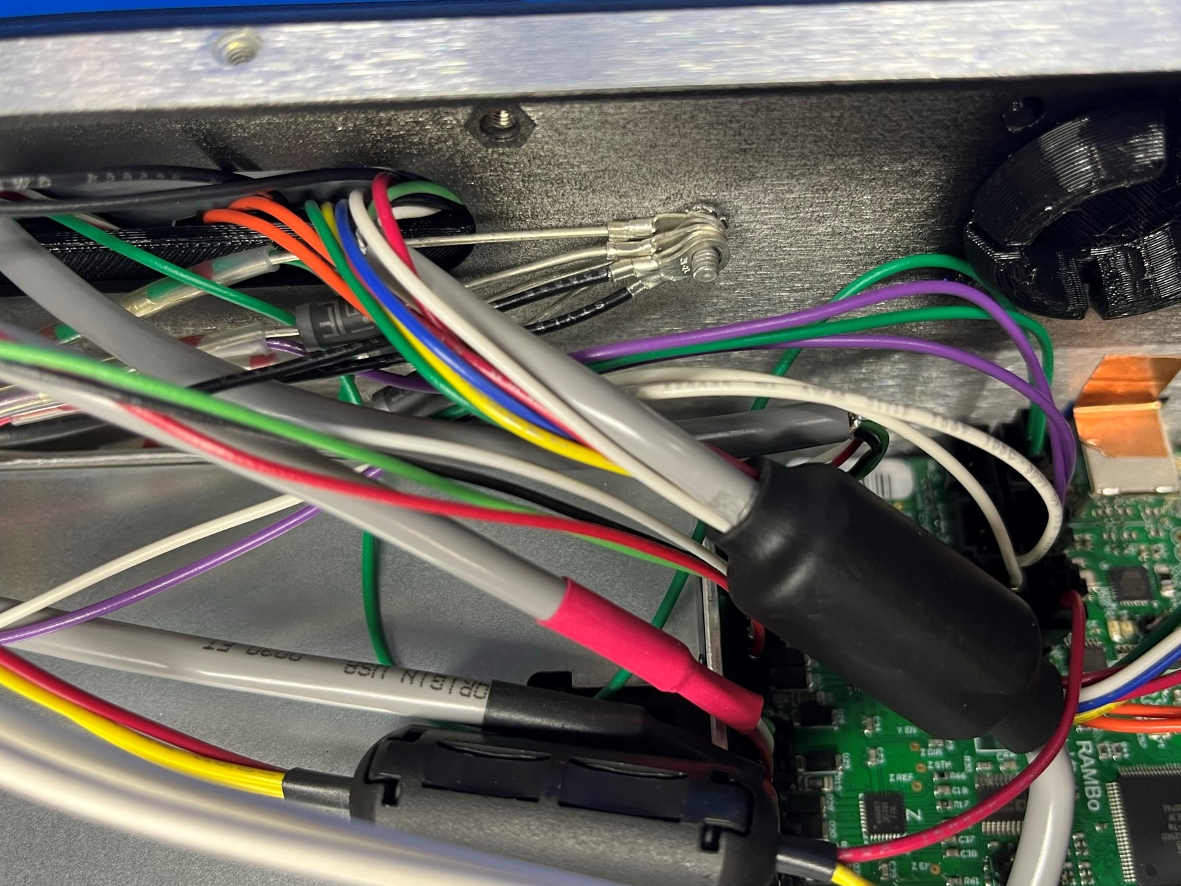
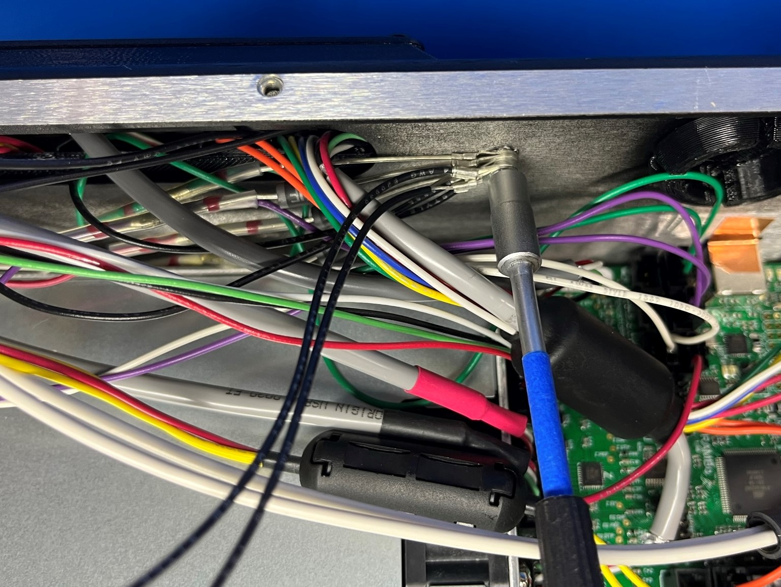
Gather all of the ground wires, you should have 9 of them.
Place 1x M3 lock washer [HD-WA0035] to the ground post on the side of the chassis.
Stack all 9 ground wire rings on the post and secure with one M3 lock nut [HD-NT0001] then tighten.
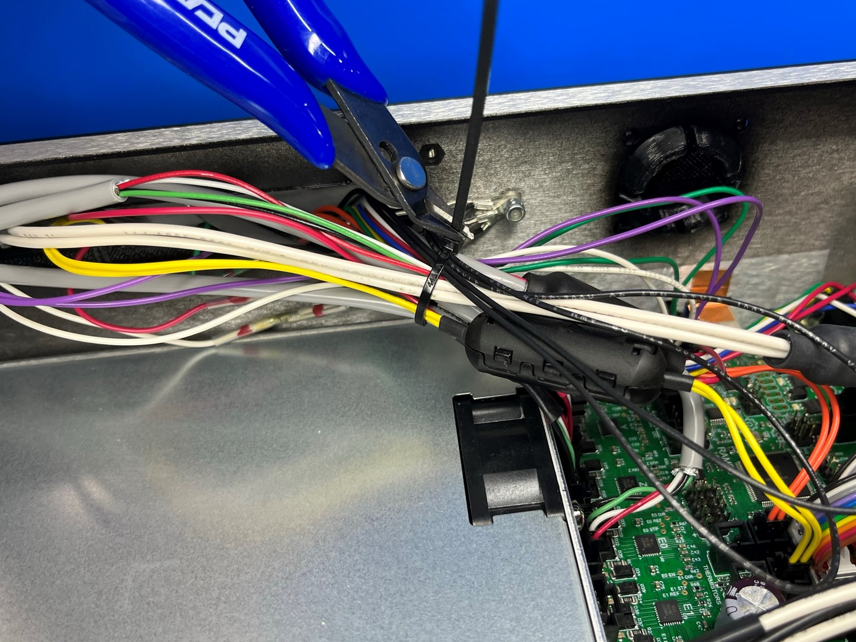
Now secure the harnesses with 1x cable tie [HD-MS0058] as pictured. You may need to loop some of the longer wires.
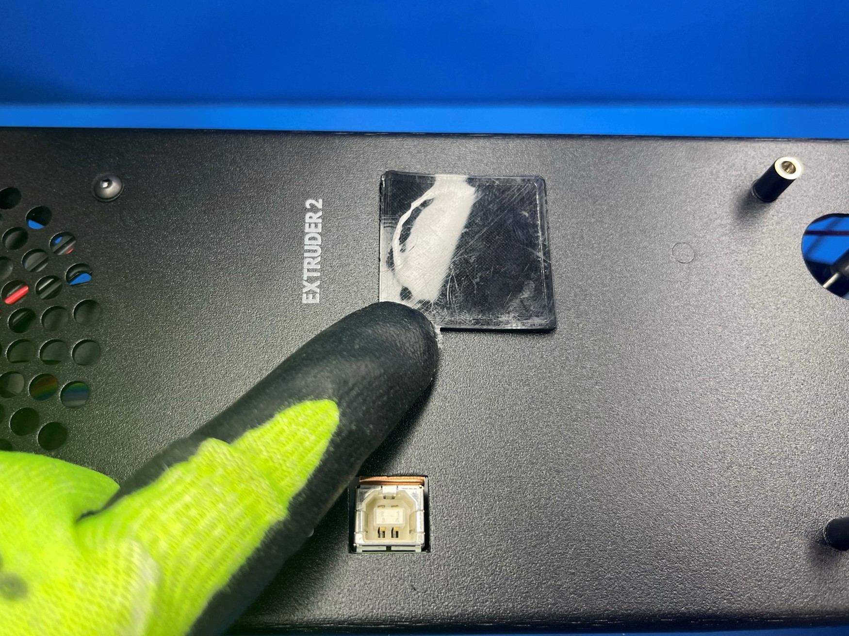
Flip the control box chassis over so that the backside is facing up.
Take the control box extruder plug [PP-GP0496] and place it inside the extruder 2 hole on the backside of the chassis.
Then place the interconnect housing [PP-GP0438] over the six standoffs making sure the opening aligns with the chassis opening.
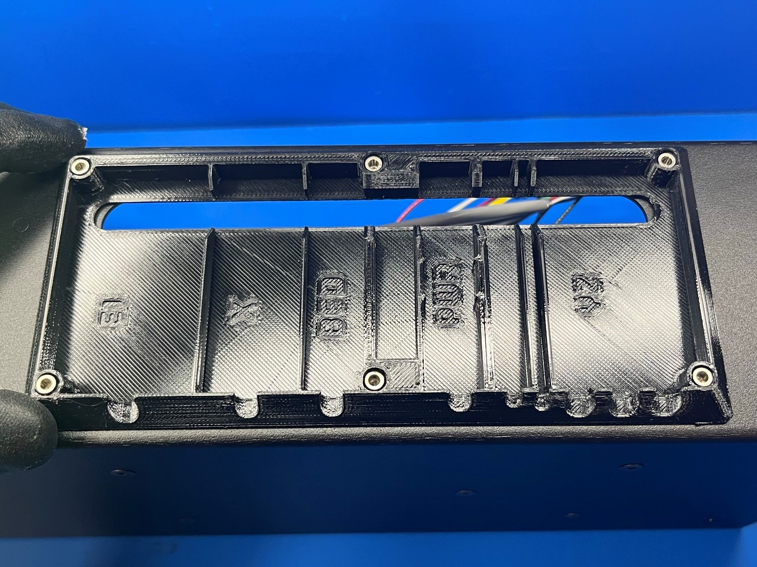
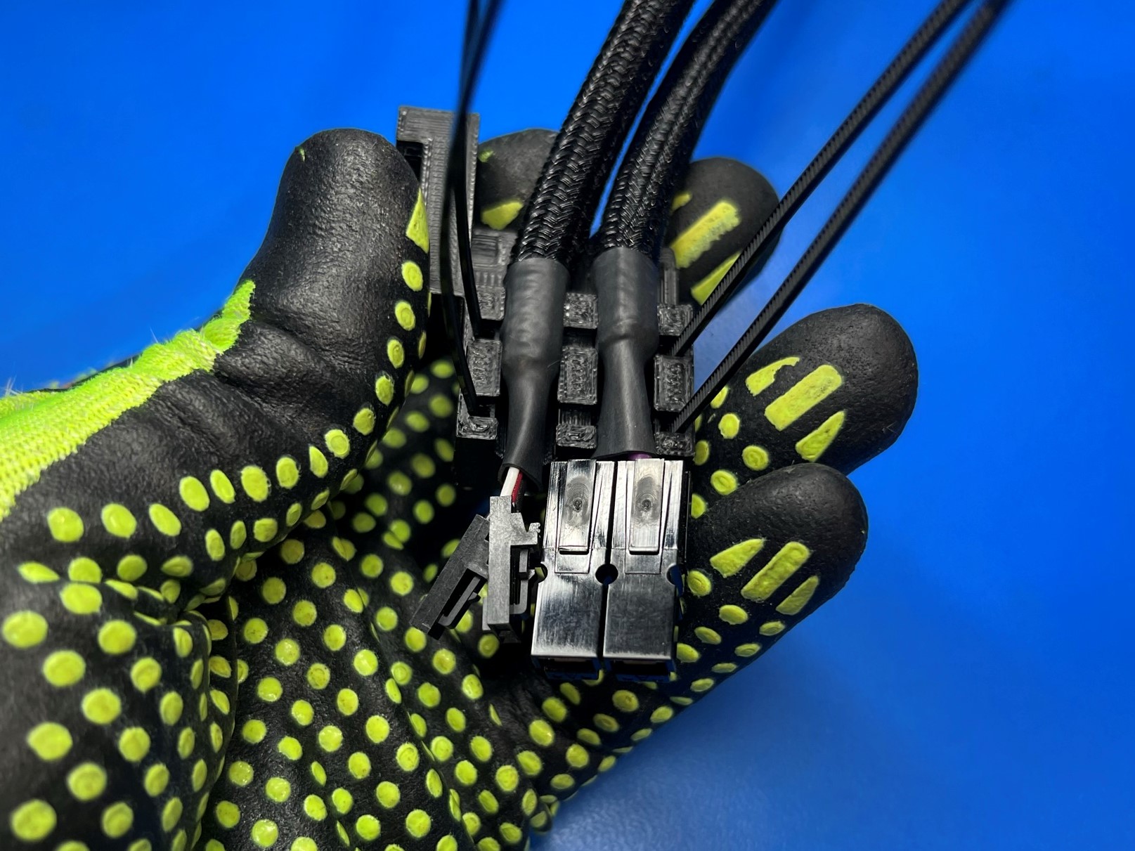
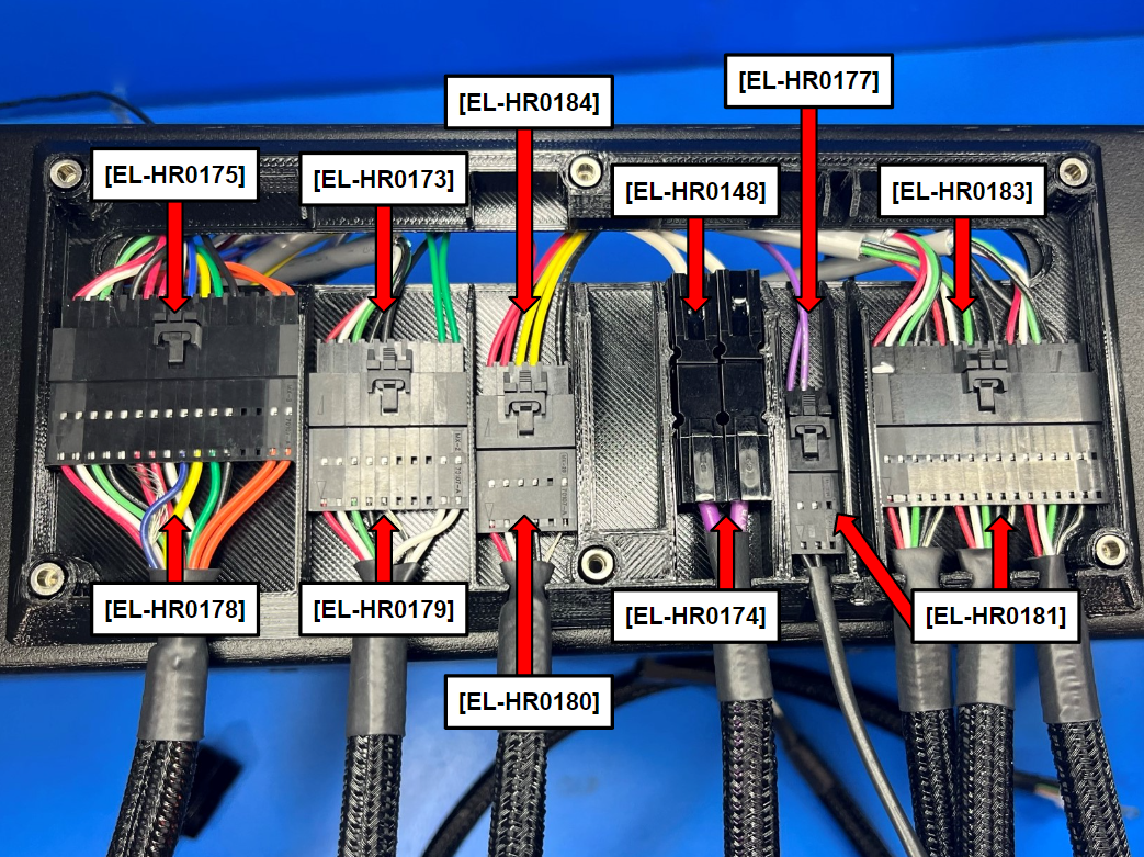
Connect the following harnesses through the interconnect housing and place the connectors in the designated slots.
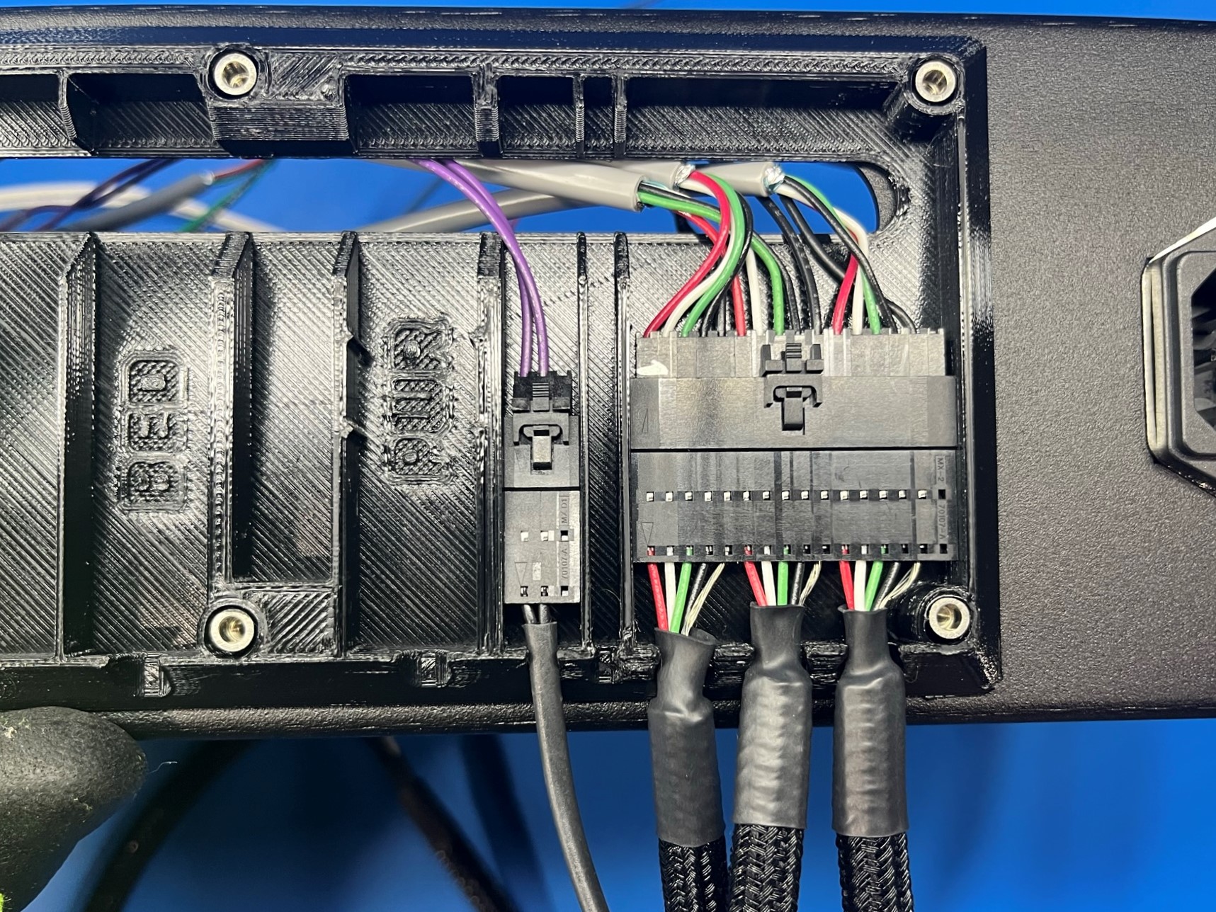
CB YZ harness to YZ harness [EL-HR0181] in slot YZ
CB Y endstop harness to small connector in [EL-HR0181] in slot next to PWR
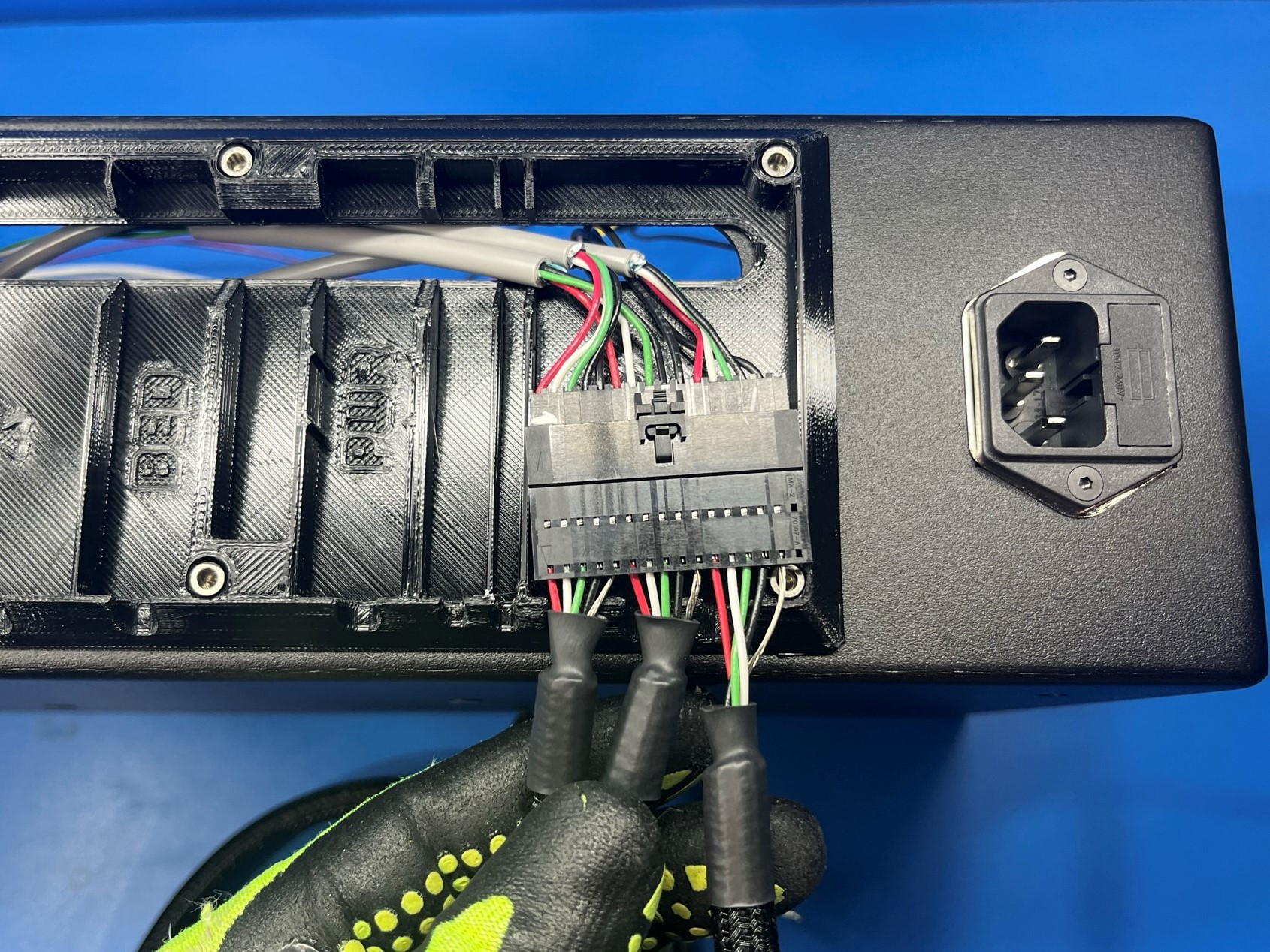
CB bed power harness to bed power harness [EL-HR0174] in slot PWR
CB bed harness to Y bed harness [EL-HR0180] in slot BED
CB X harness to X harness [EL-HR0179] in slot X
CB extruder harness to extruder harness [EL-HR0178] in slot E1
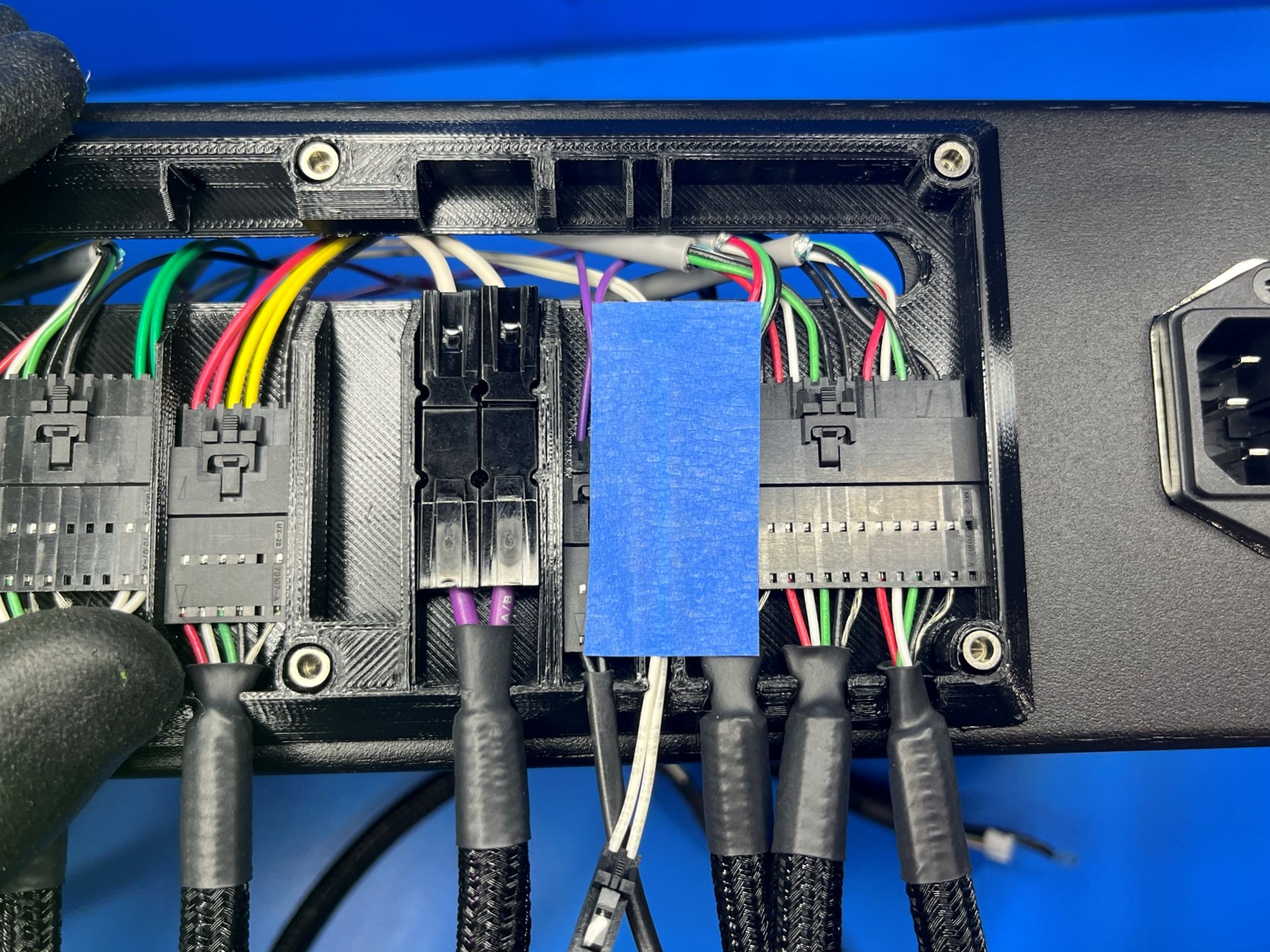
Once all the harnesses are connected find the WHITE CB Z endstop harness and feed it through the smallest slot in the interconnect housing next to the YZ slot.
Leave the end of the harness sticking out about a half inch, then place a piece of BLUE tape over the wire to hold it in place.


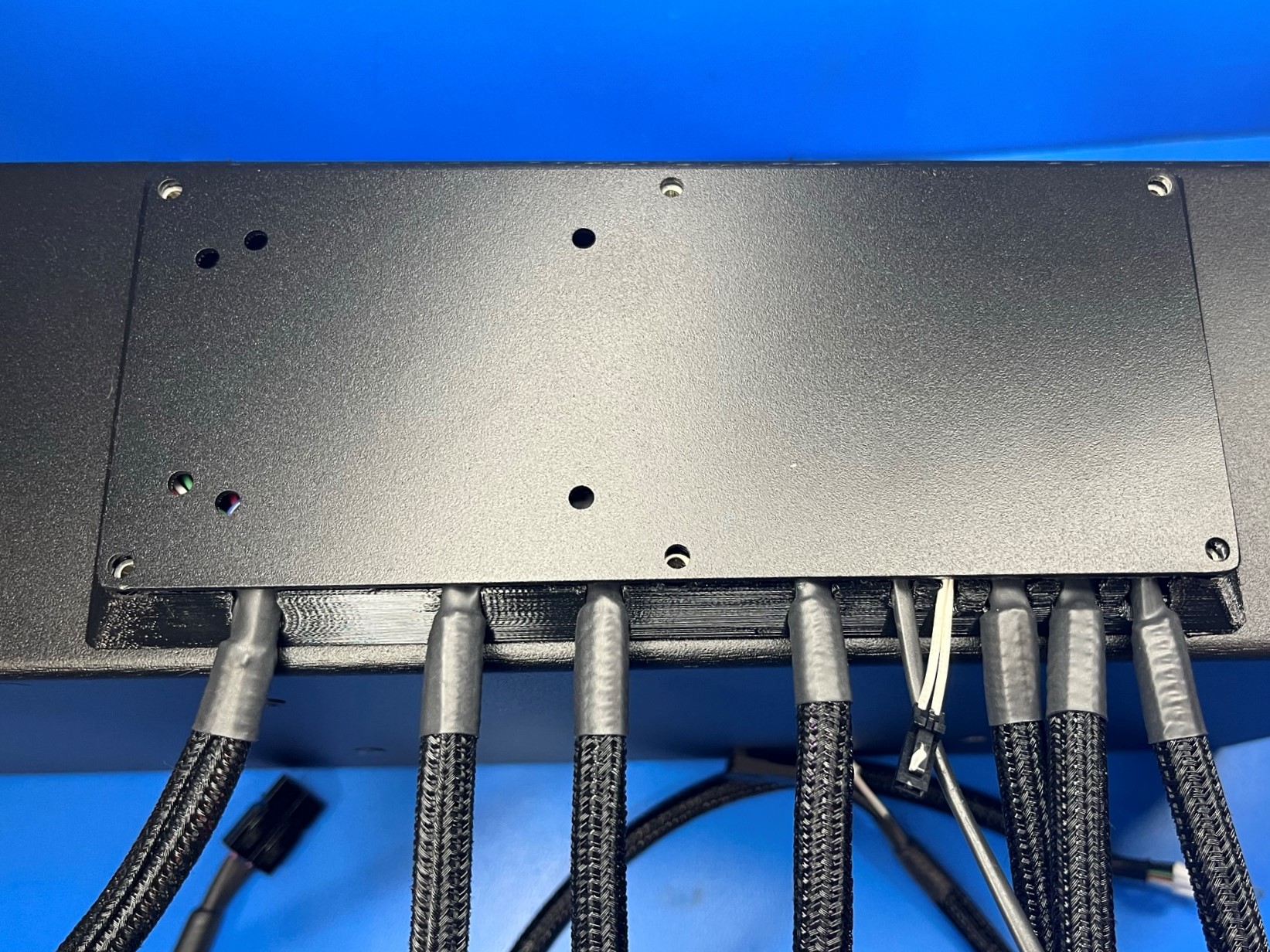
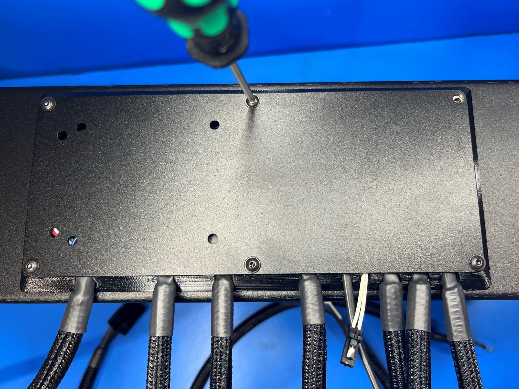
Place the interconnect cover [PP-FP0153] over the cables with the extra holes towards the top.
Ensure no wires are pinched
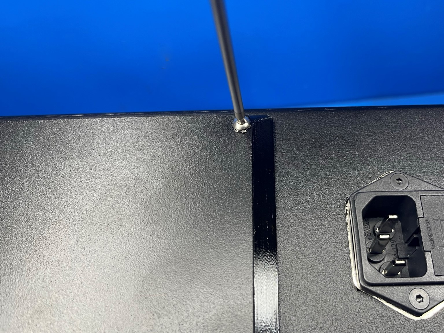
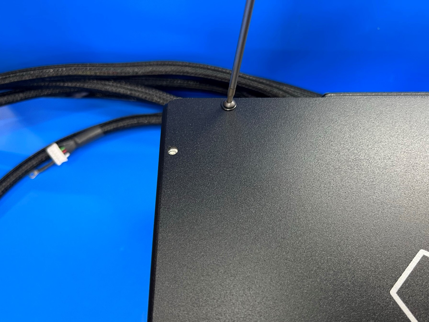
Secure the interconnect cover using 5x M3x8 BHCS [HD-BT0137] with washers [HD-WA0038] as shown [reference#1].
Use 1x M3x10 Stainless BHCS [HD-BT0234] and 1x lock washer [HD-WA0035] for the last hole.
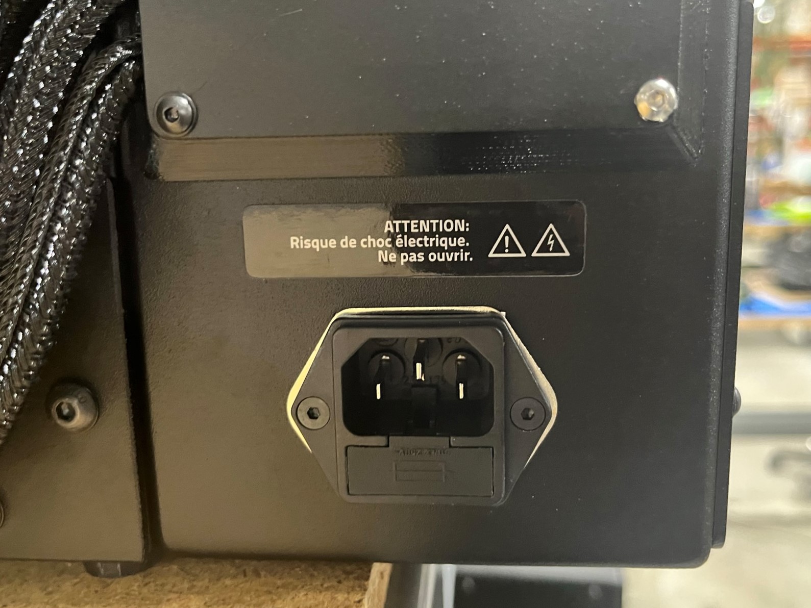
Now place the electric warning sticker, French [DC-LB0208] above the power inlet, just below the interconnect housing.
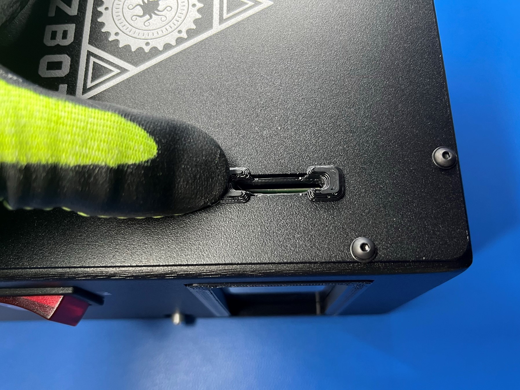
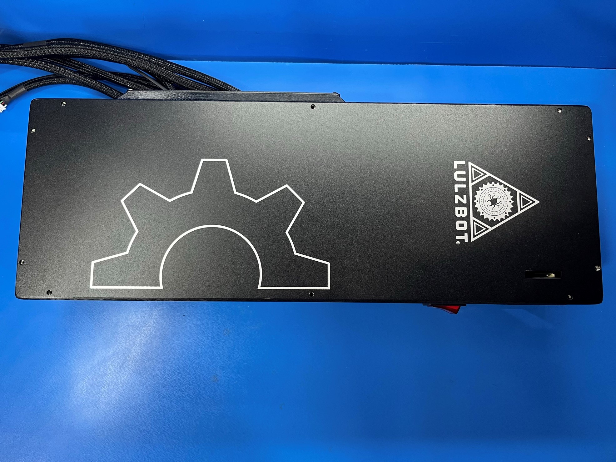
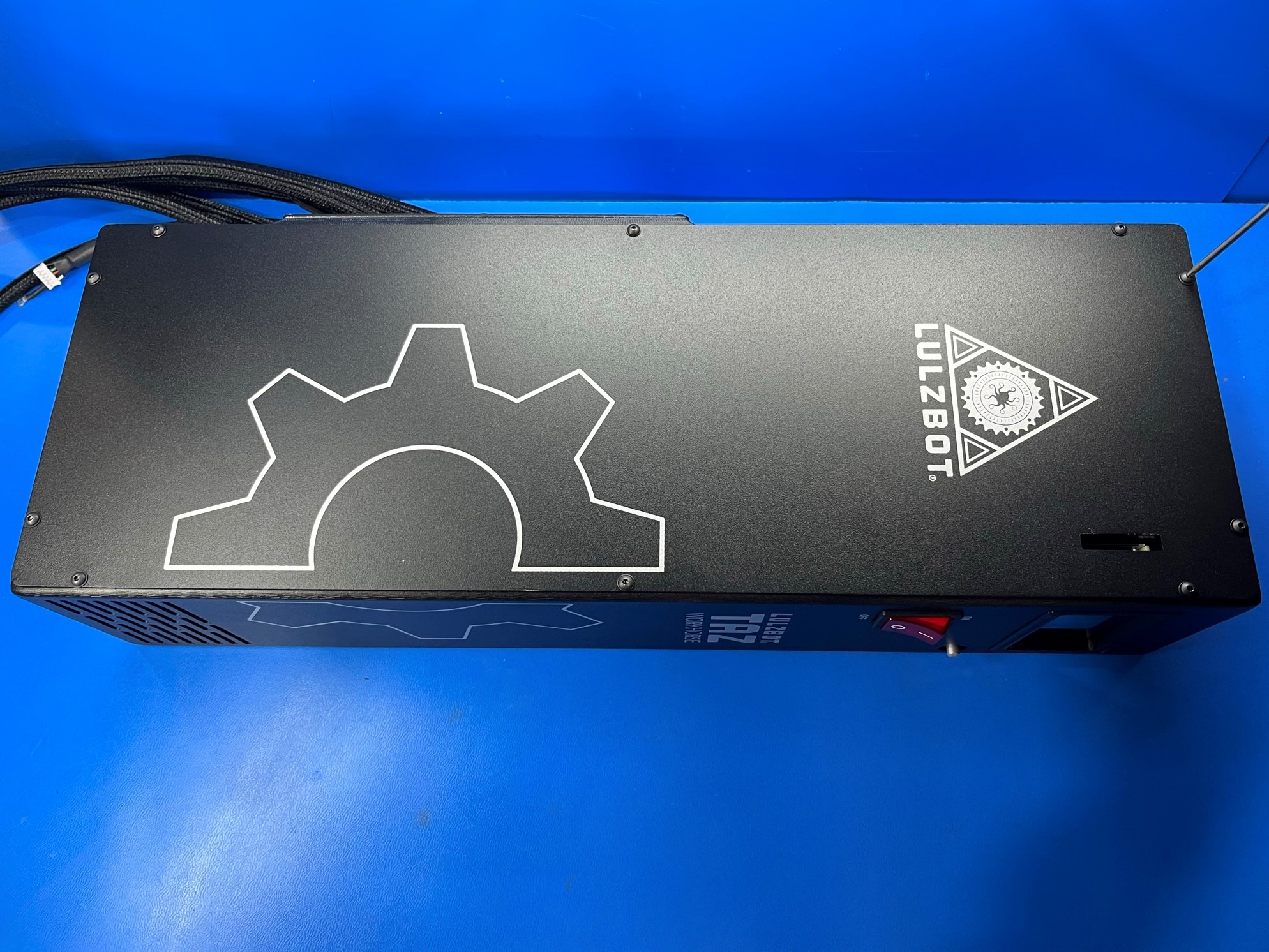
Place the electronics chassis cover [PP-FP0164] over the chassis with the LulzBot logo towards the top of the chassis. Ensure the SD card slot is properly aligned
Once the chassis cover is aligned with the chassis use 10x M3x6 BHCS [HD-BT0140] with washers [HD-WA0038] to attach the cover.
Slide 2x cable ties [HD-MS0058] through the slots on the Y cable mount [PP-GP0440] making sure the heads of the cable ties are on the same side.
Then align the Y cable mount with the bed harness and the bed power harness. Make sure the larger PURPLE harness is on the right side or the flat side.
Then take the SD card bezel [PP-GP0235] and place it inside the SD card slot on the electronics chassis cover [PP-FP0164] by the LULZBOT logo.