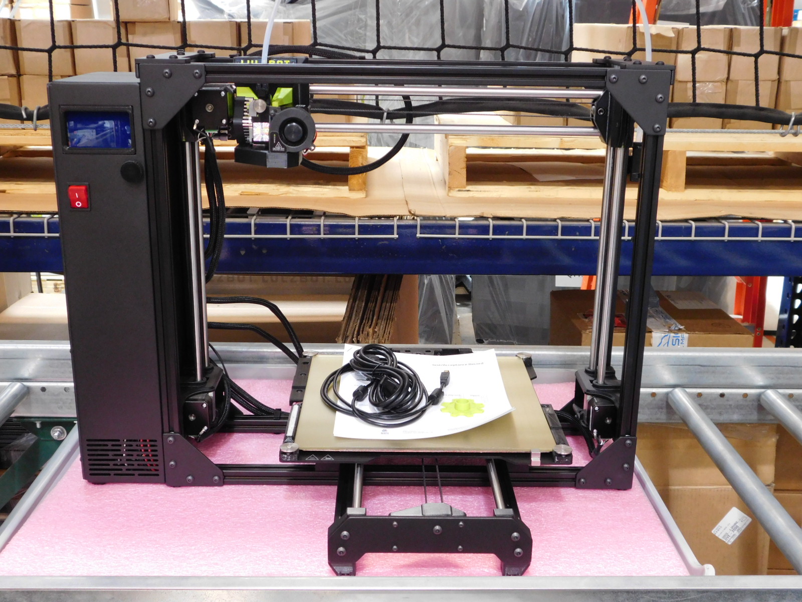
Open HardwareAssembly Instructions
Guides for installation and assembly of the LulzBot line of products made by FAME 3D LLC.
Guides for installation and assembly of the LulzBot line of products made by FAME 3D LLC.
Begin filling out the Quality Assurance record;
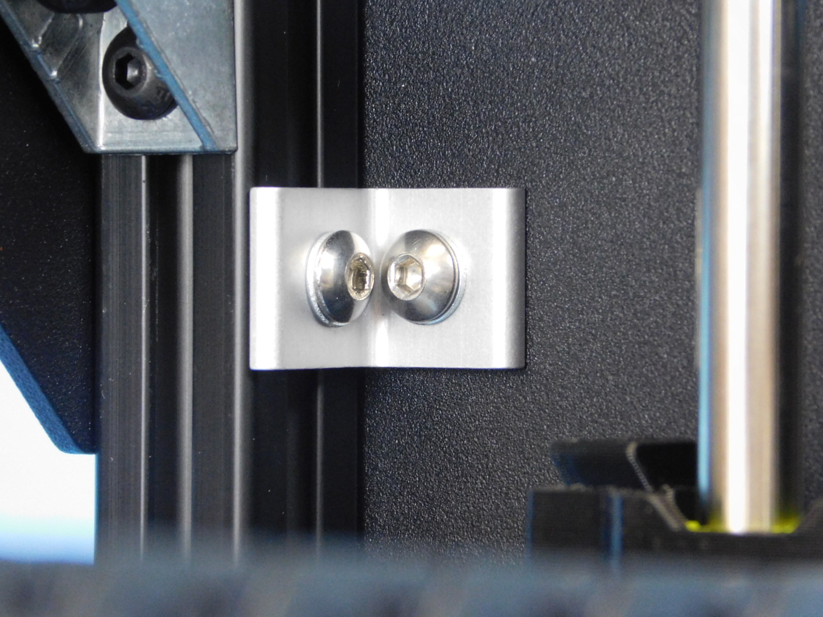
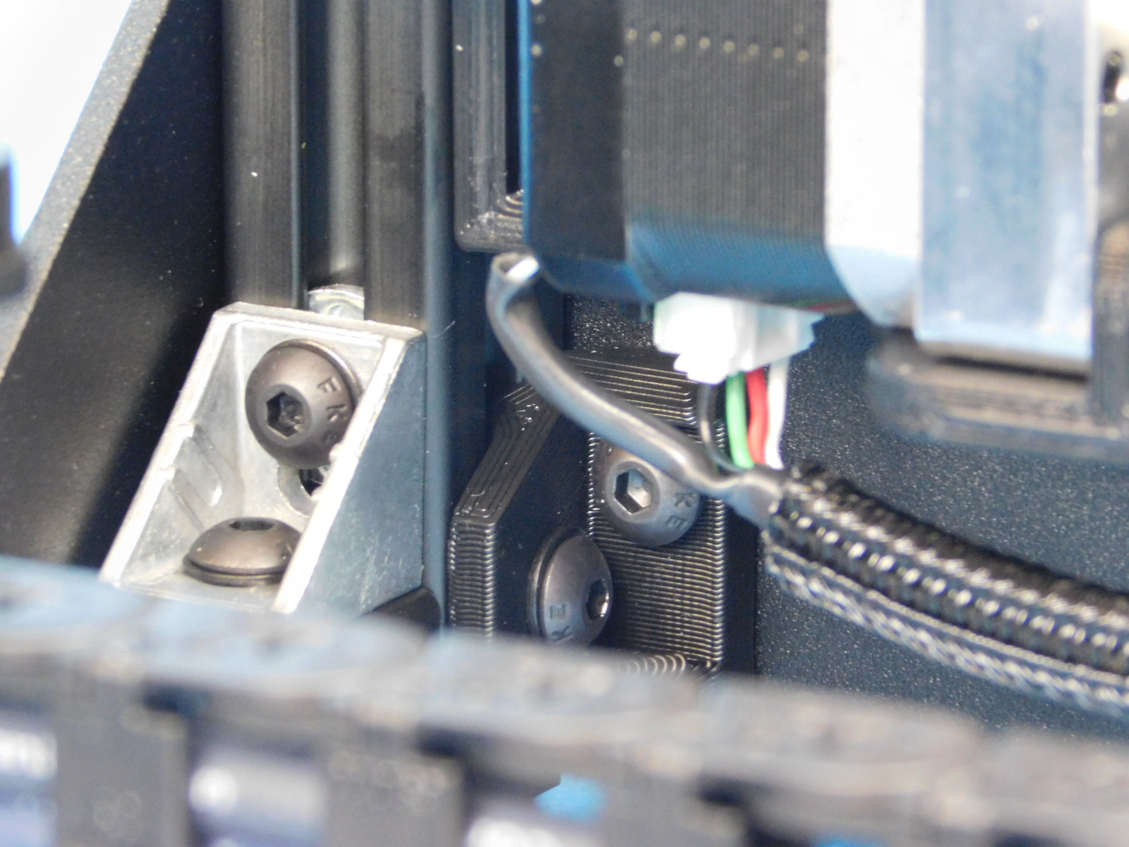
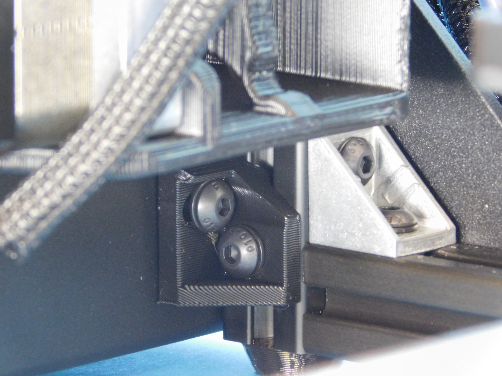
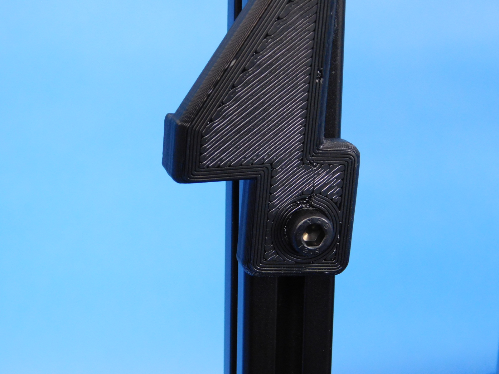
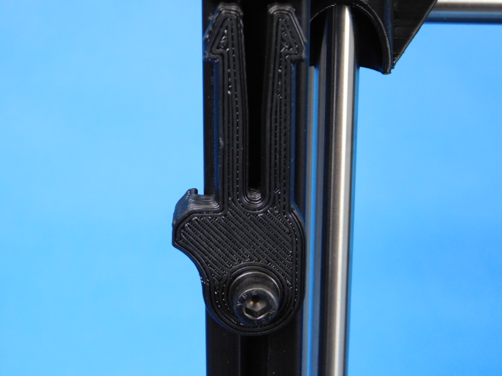
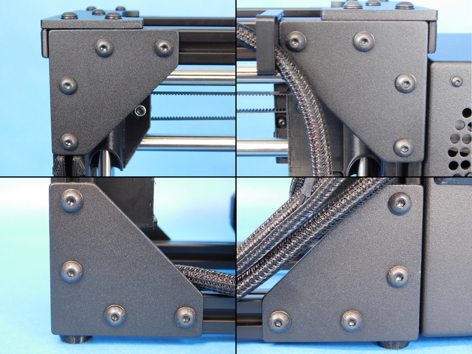
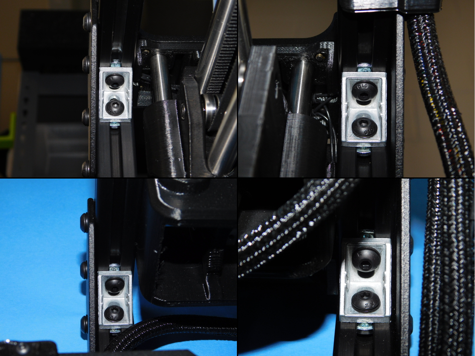
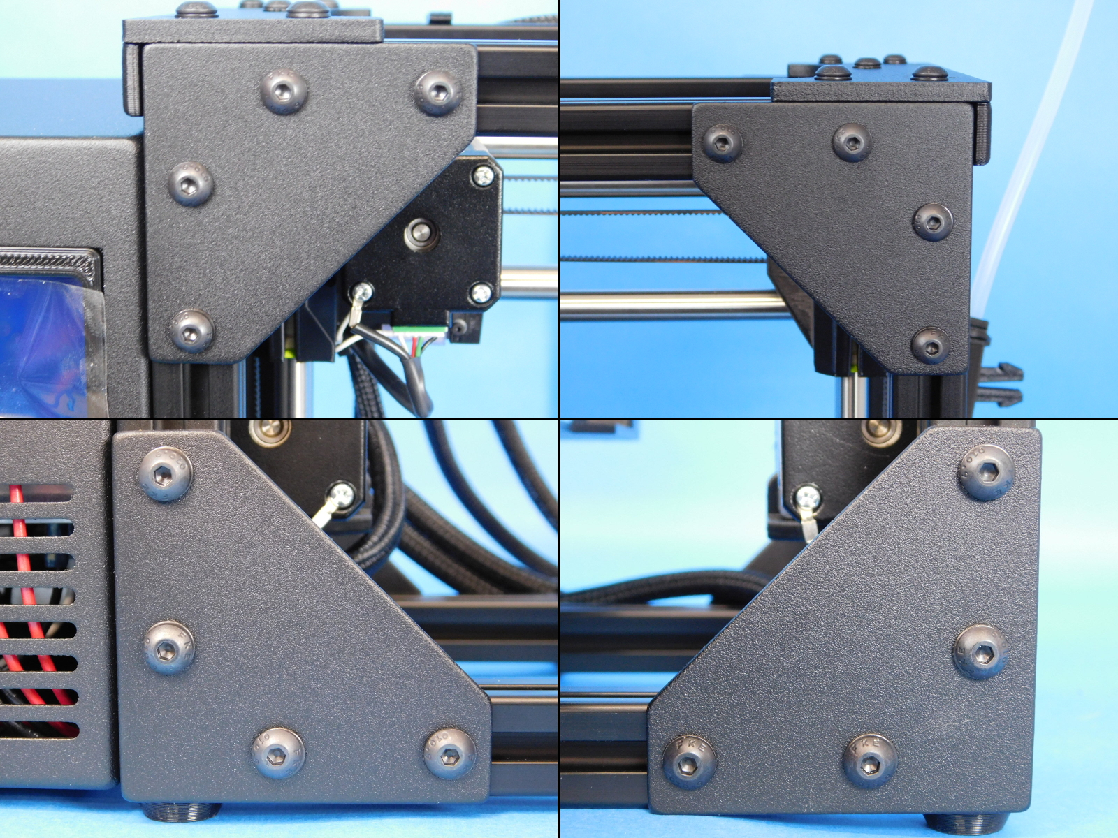
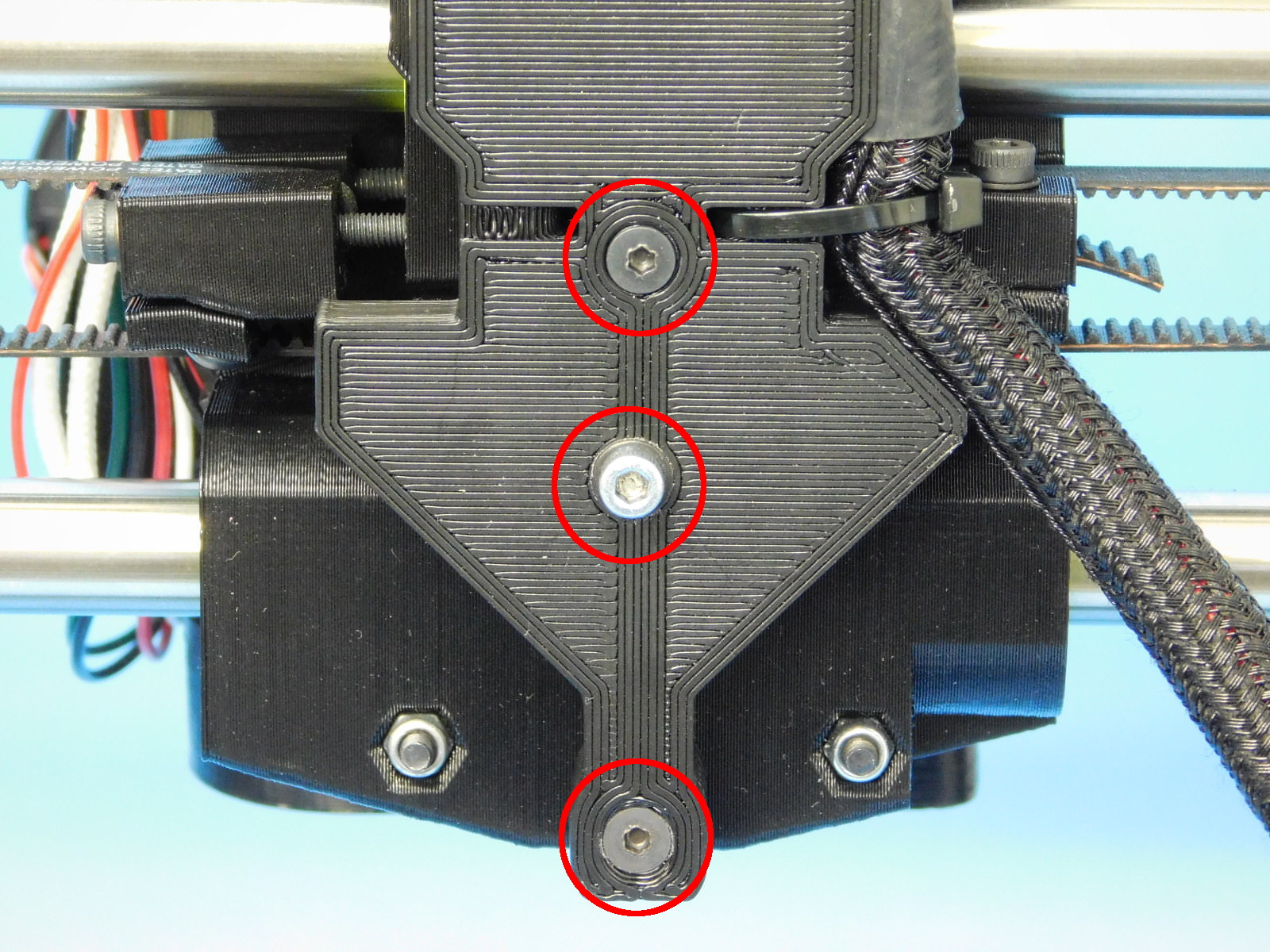
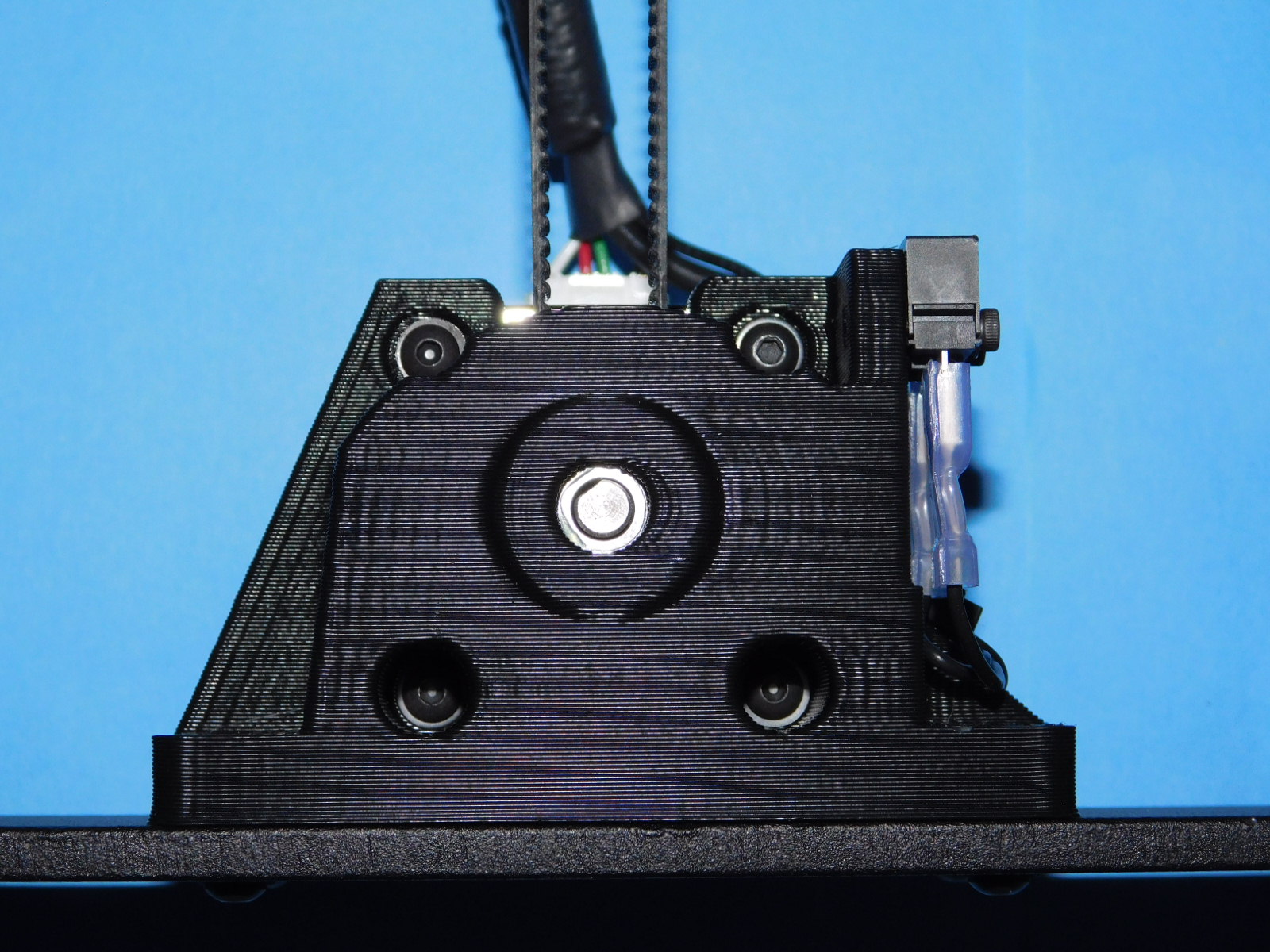
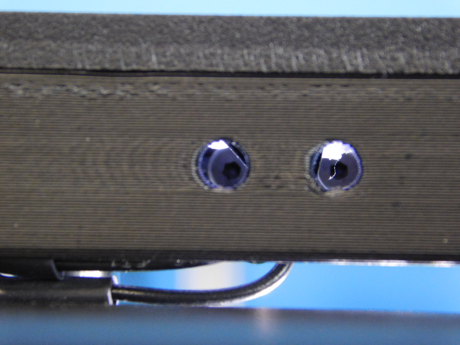
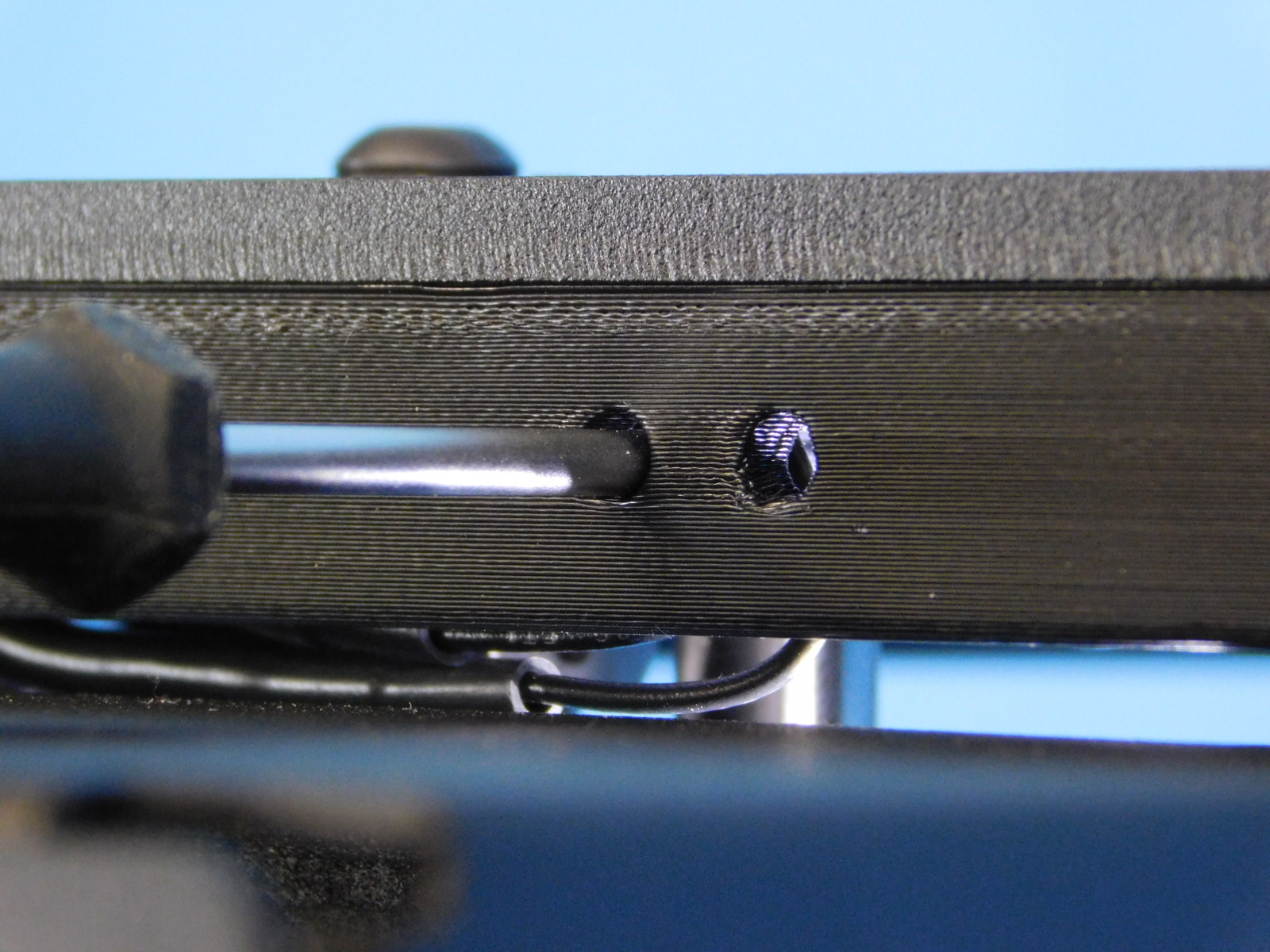
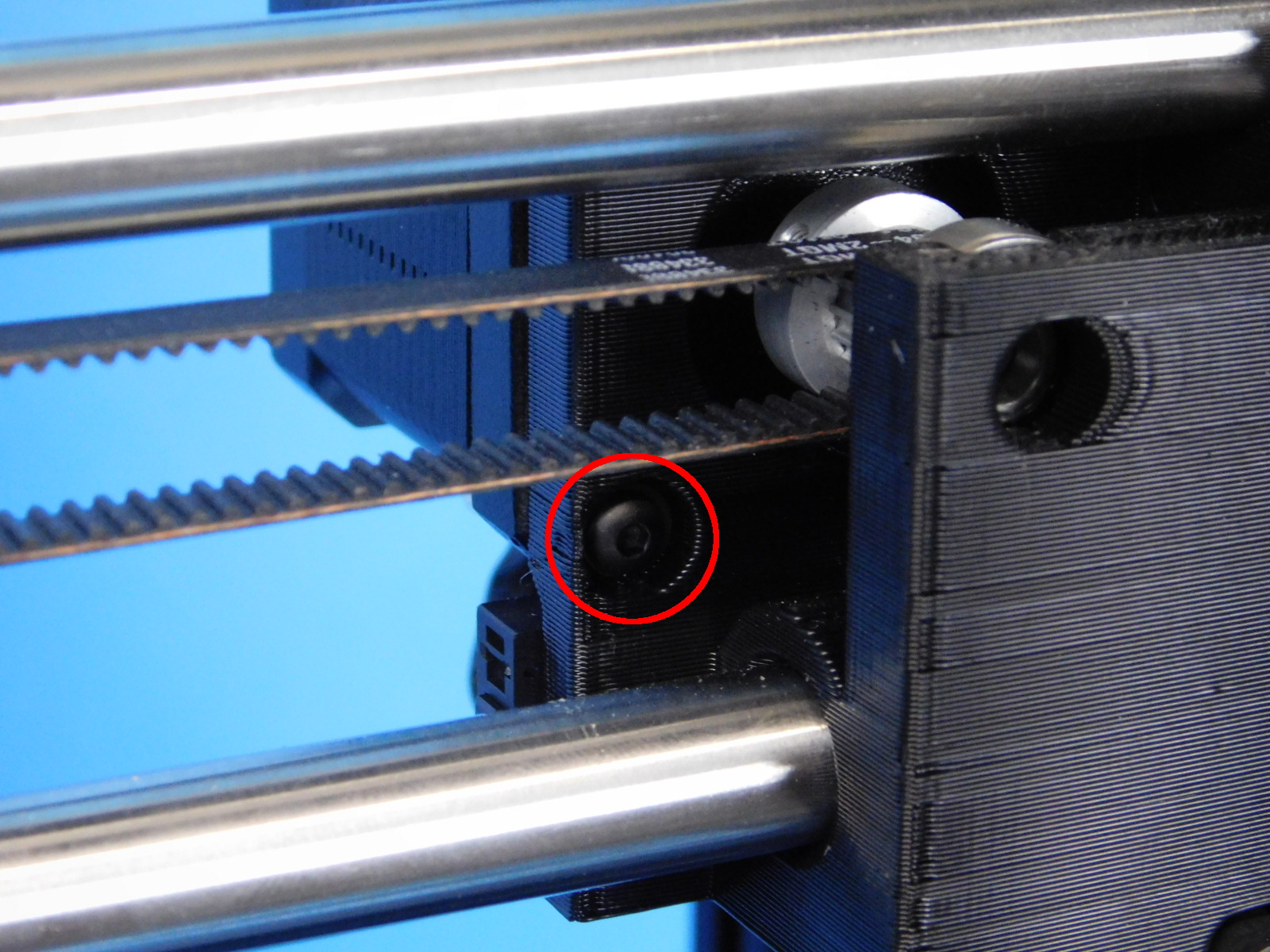
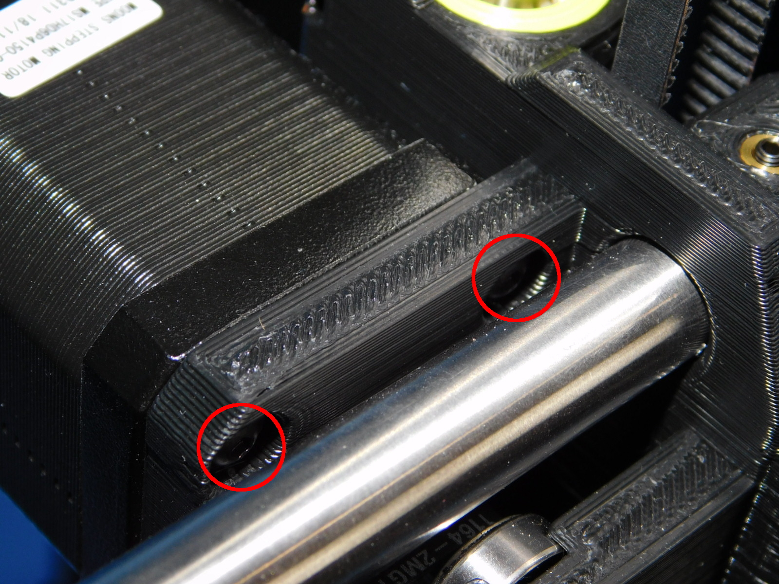
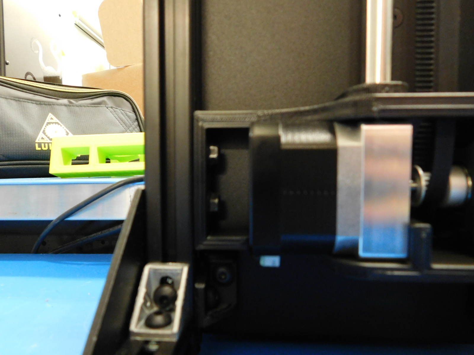
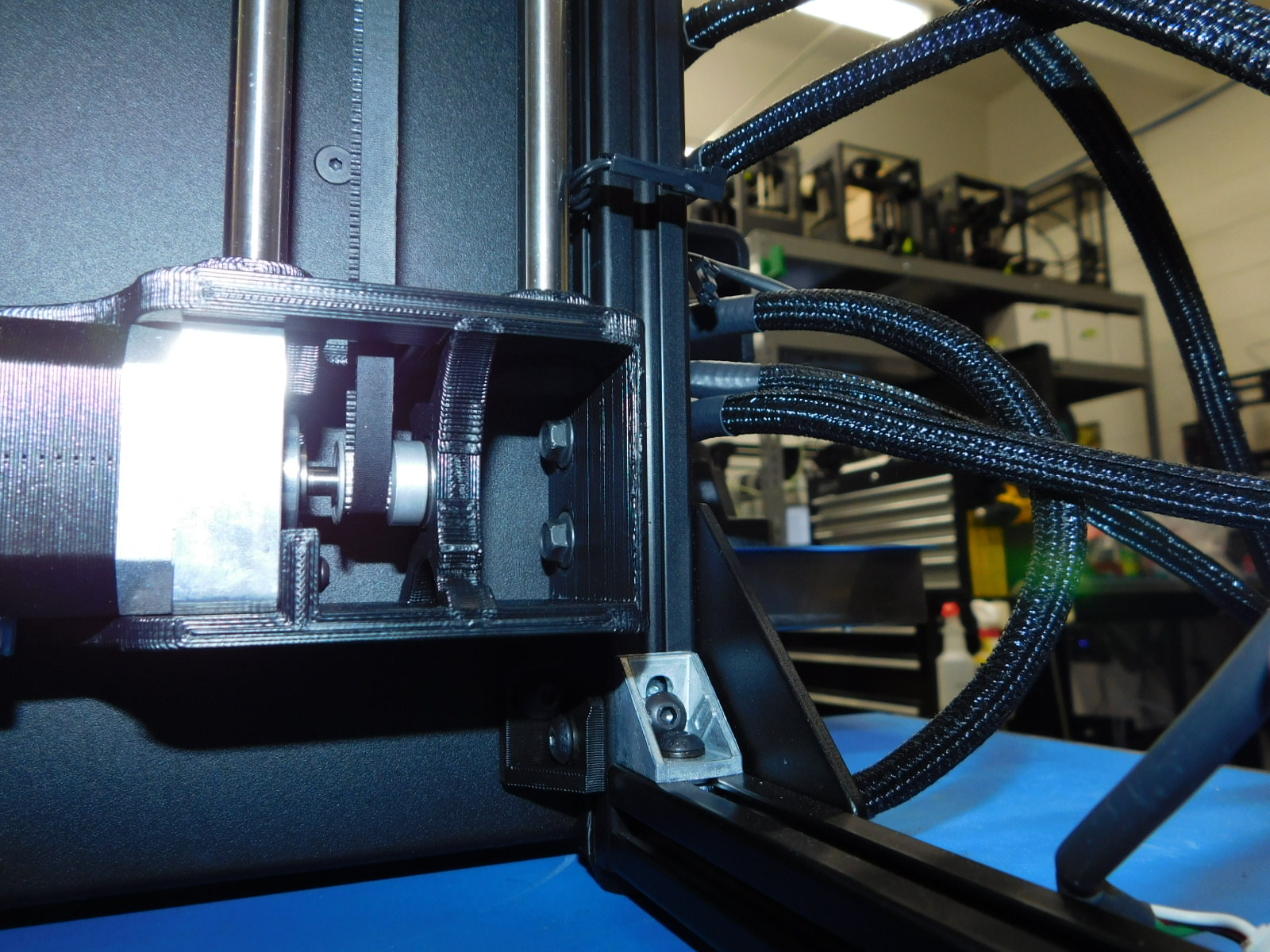
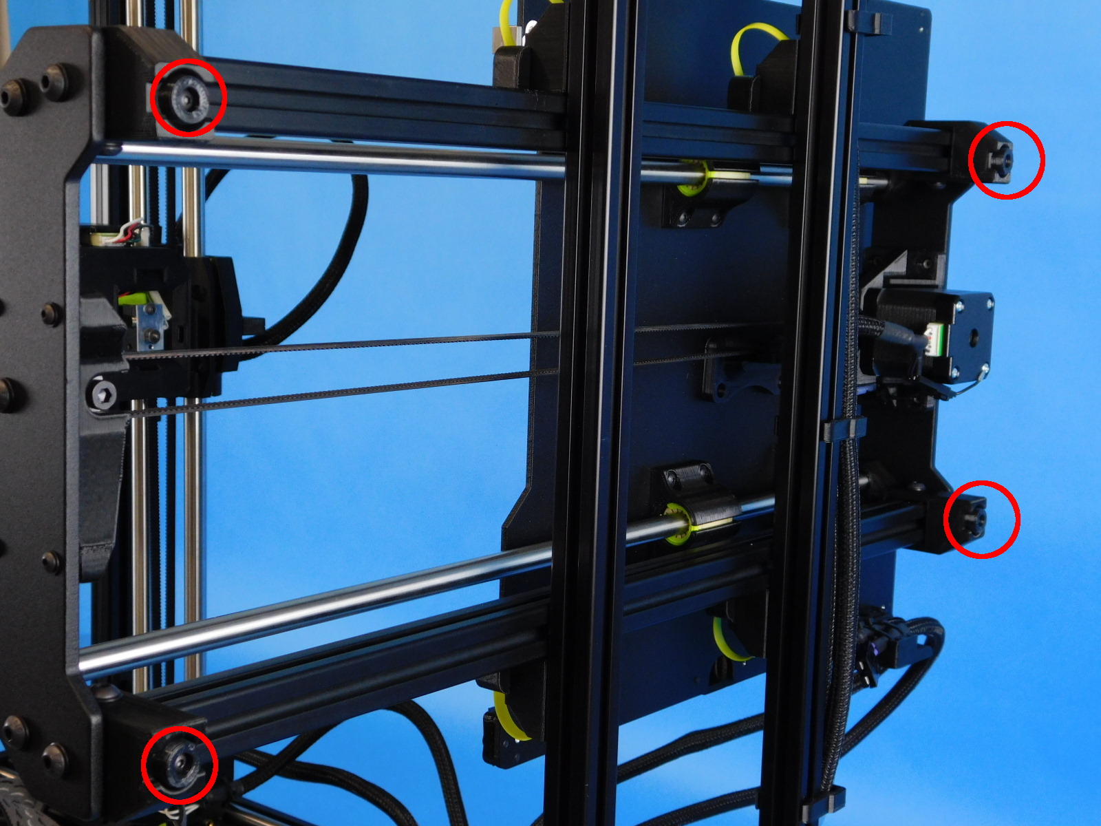
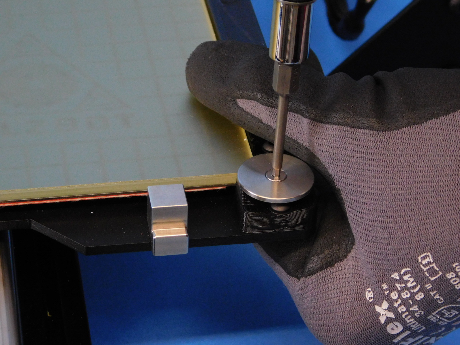
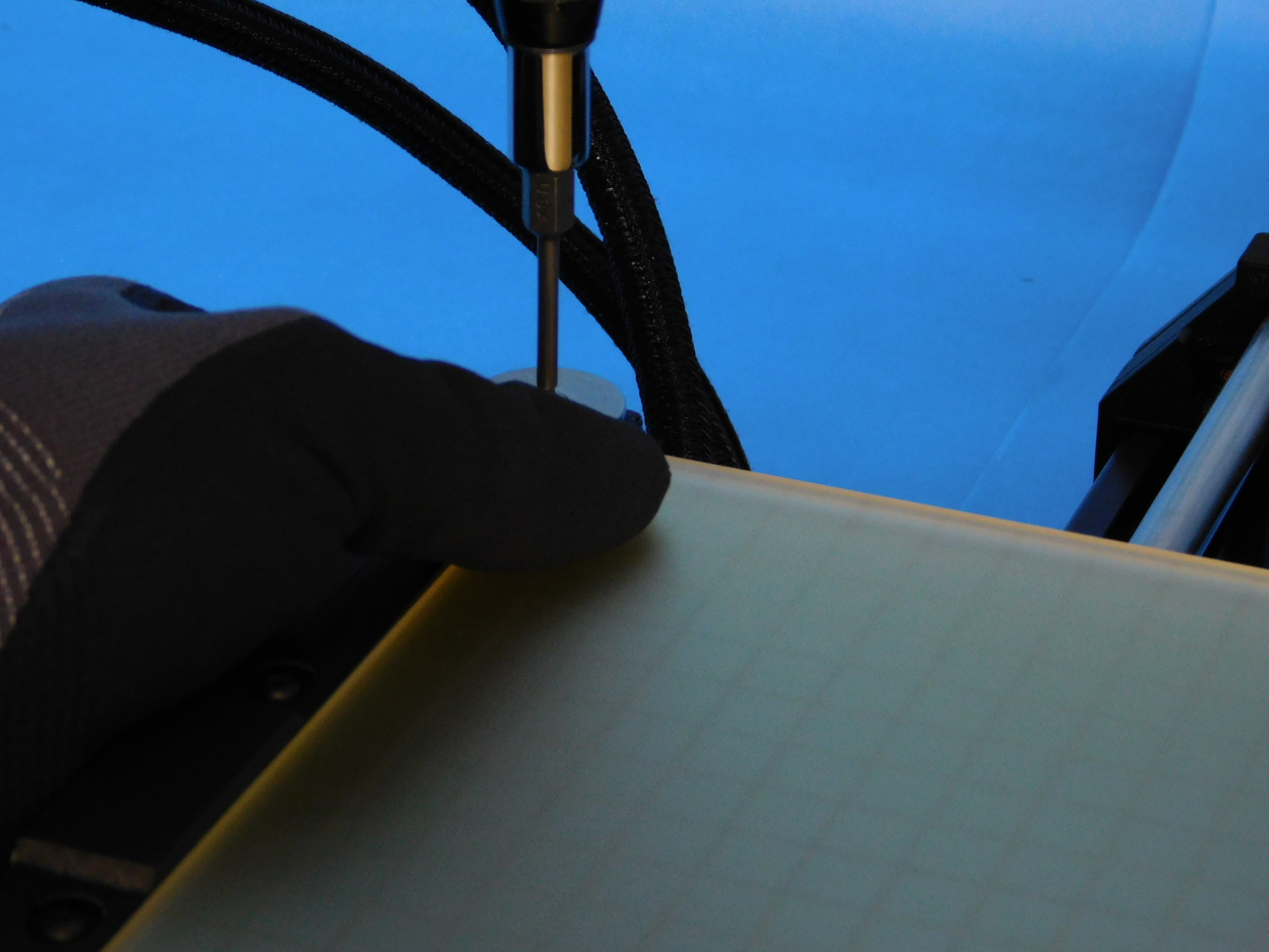
Check that all hardware is present and properly torqued.
Some of the following fasteners may not be reachable in the final assembly, verify everything that is reachable.
Torque Values:
Spool Arm: 5 in*lbs
Frame: 40 in*lbs
Y End Plate: 5 in*lbs
Y corner Left/Right: 5 in*lbs
Y Mount Chassis: 8 in*lbs
Z Lowers: 15 in*lbs
Z Uppers: 5 in*lbs
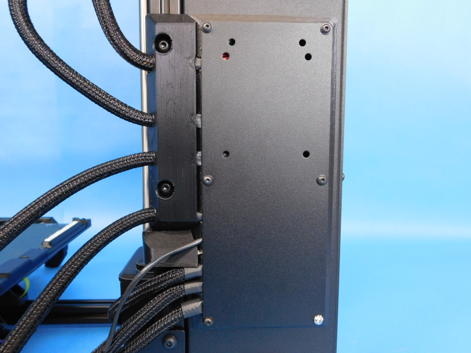
Frame to Control Box: 5 in*lbs
Toolhead: 5 in*lbs
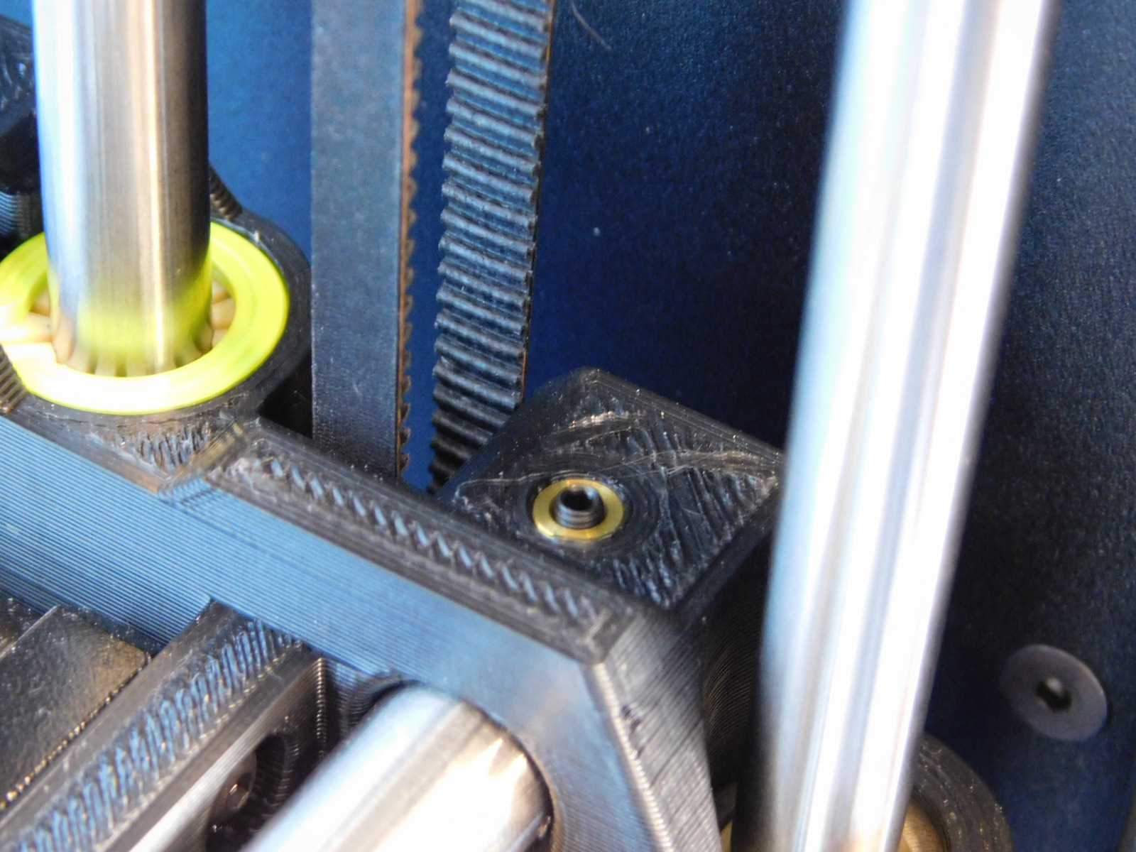
X Belt Clamp: 5 in*lbs
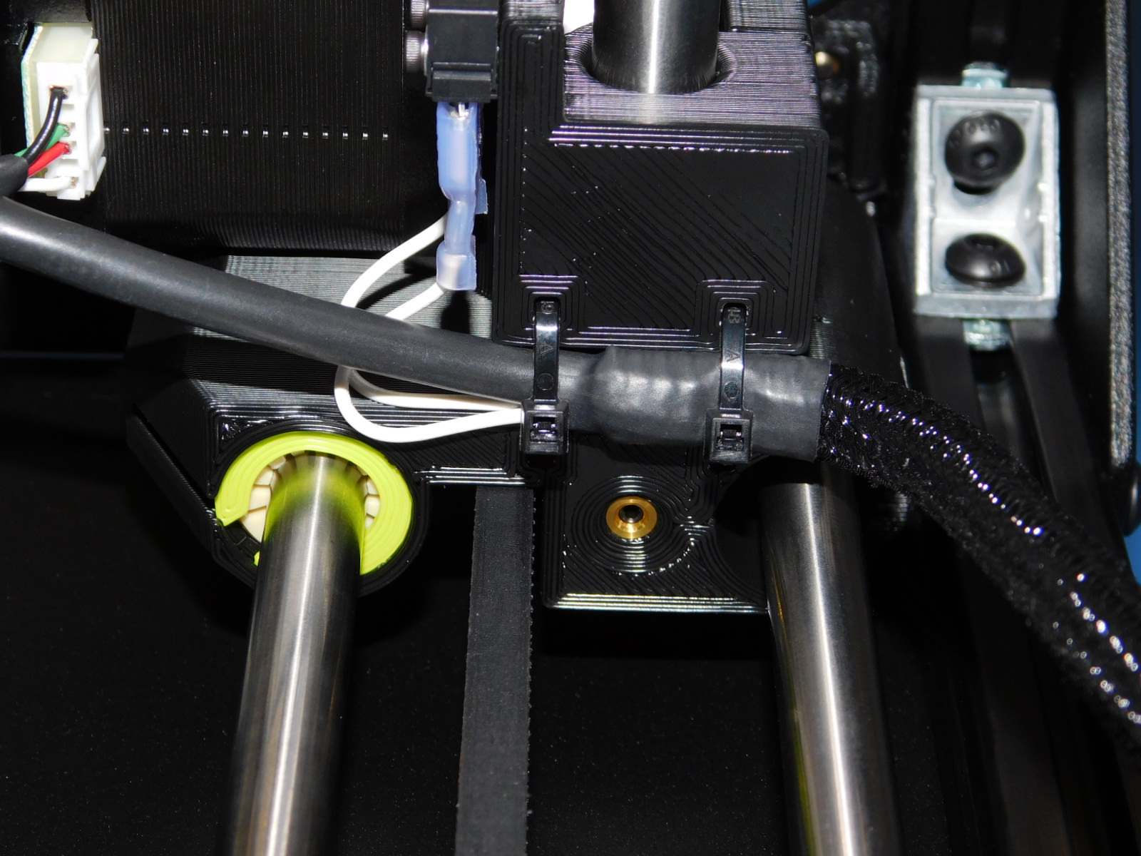
Case fan & Interconnect housing: 5 in*lbs
Bed Plate to Single Bearing: 5 in*lbs
Y Belt Mount: 5 in*lbs
Feet on Y corners: 3 in*lbs
Y Motor Mount: 5 in*lbs
Y Motor: 5 in*lbs
Y Idler Mount: 5 in*lbs
Electronics case cover: 5 in*lbs
Z Motors: 5 in*lbs
X Motor: 5 in*lbs
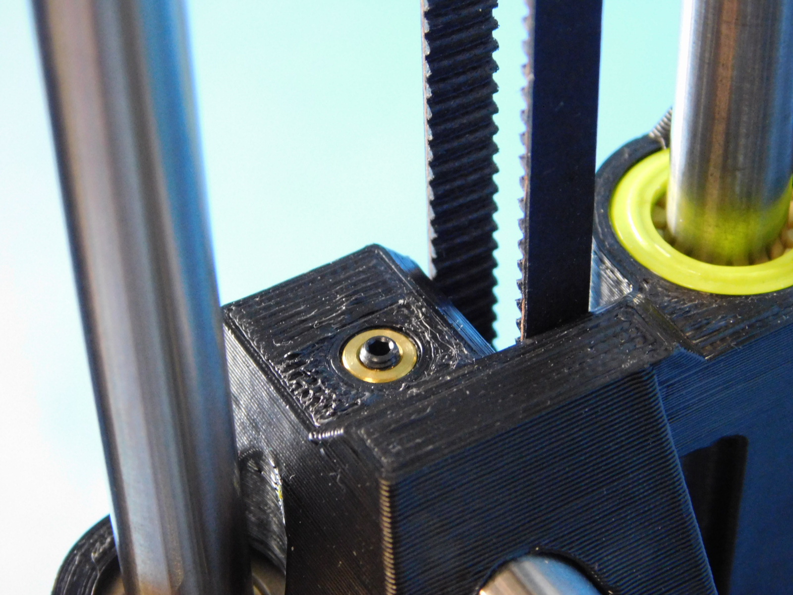
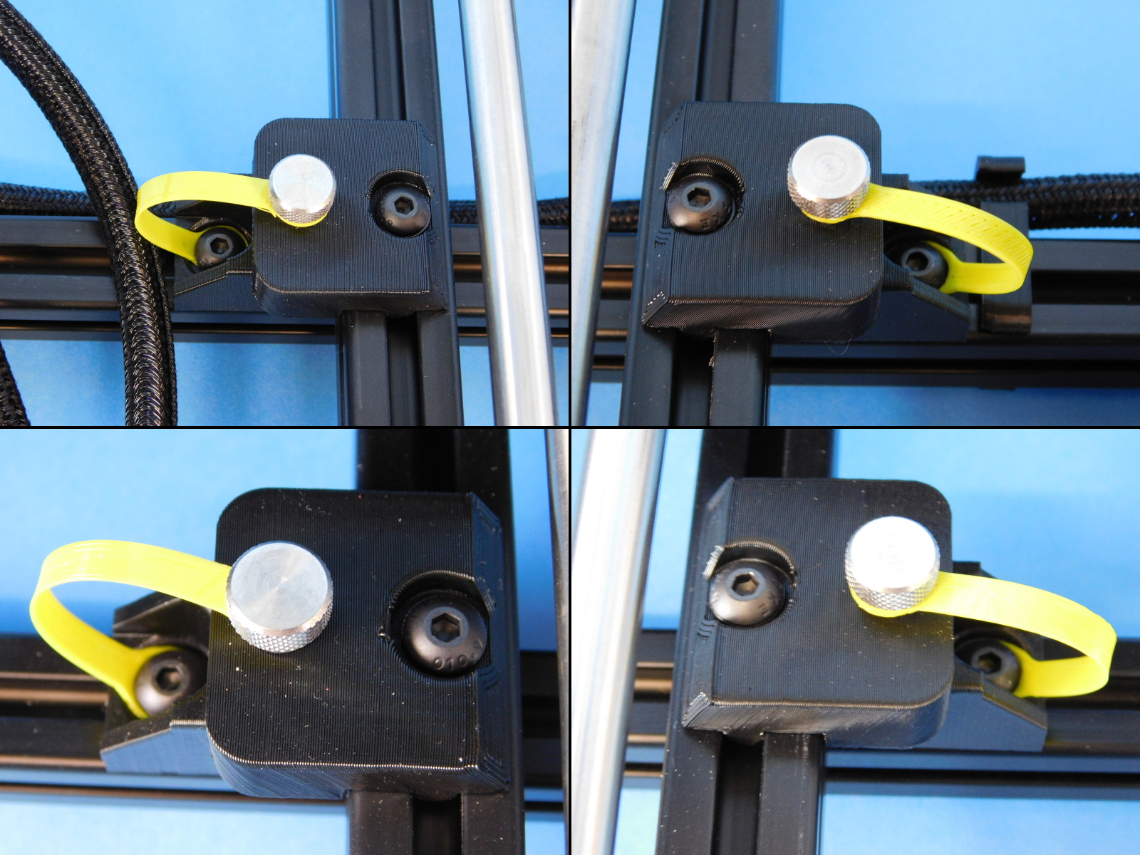
Smooth Rod Setscrew: 3 in*lbs
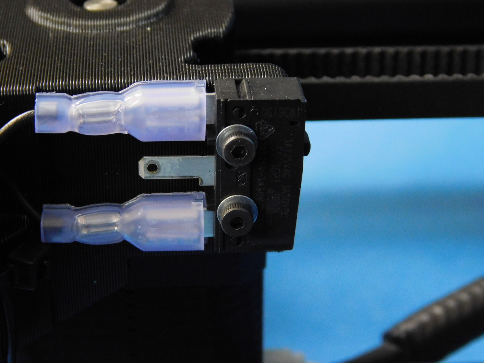
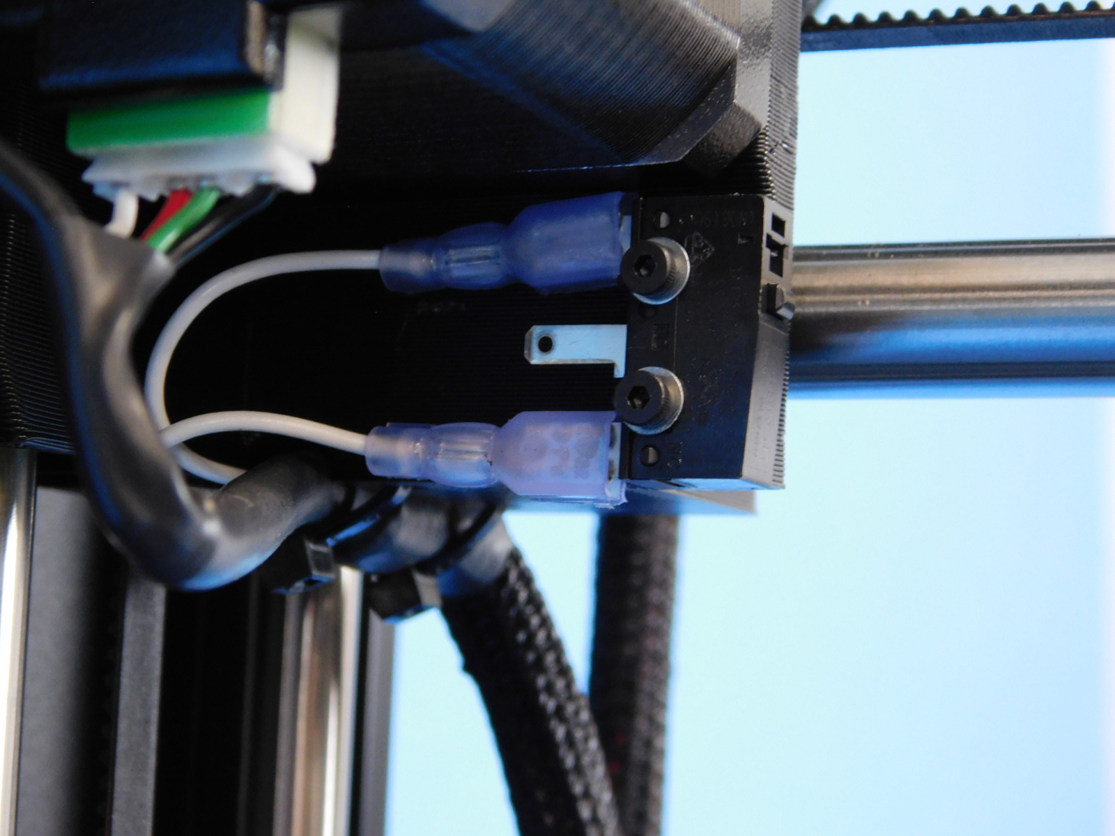
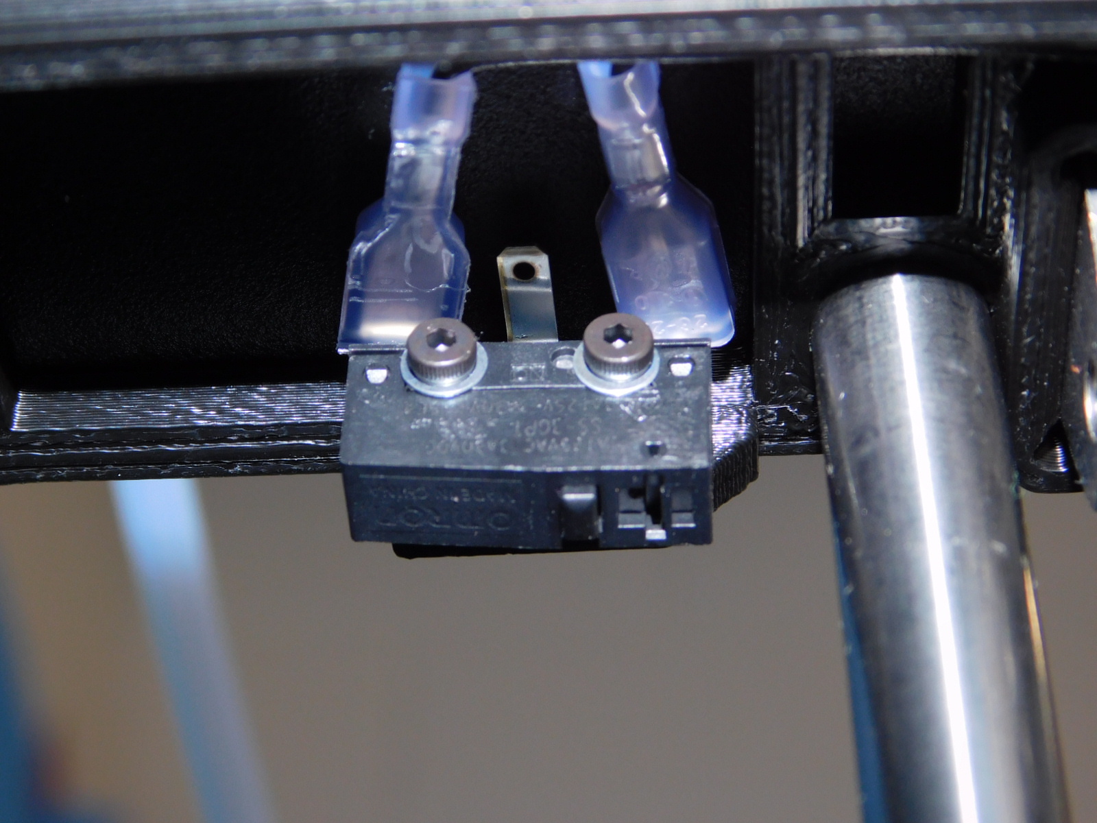
Limit Switches: 2.5 in*lbs
Bed Leveling Washers (once installed): 5 in*lbs
Wiper Mount: 5 in*lbs
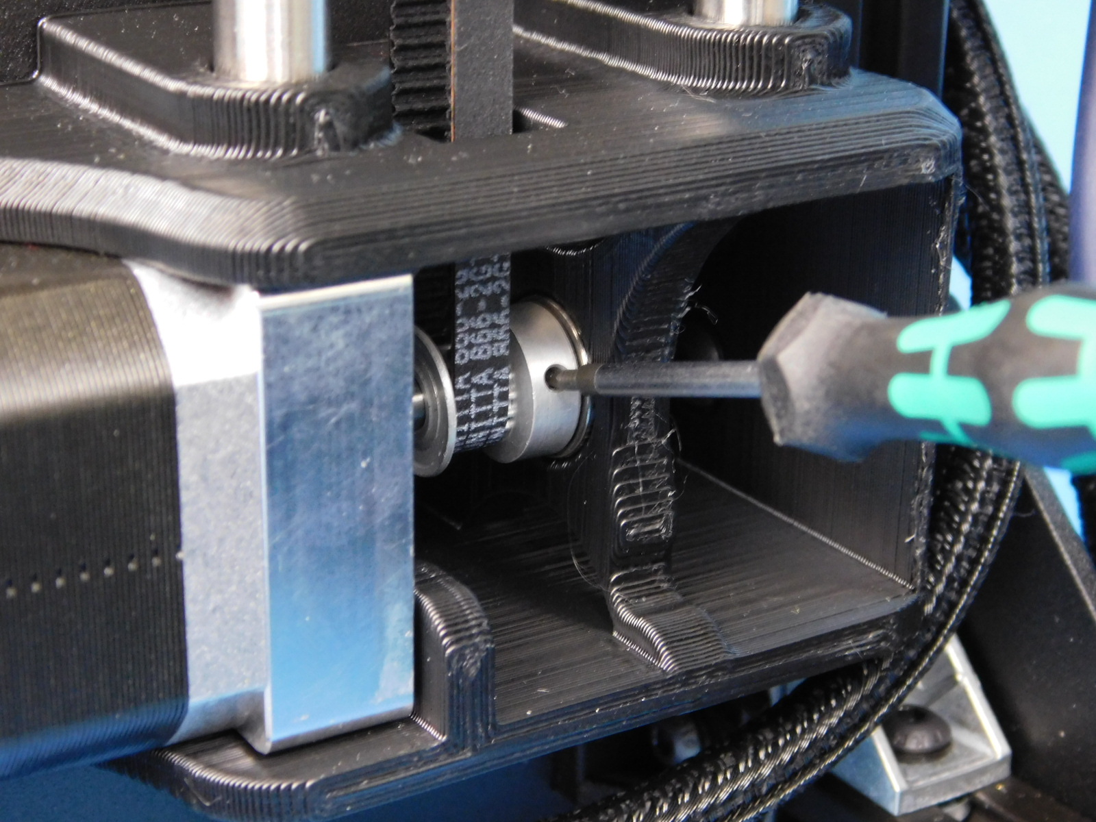
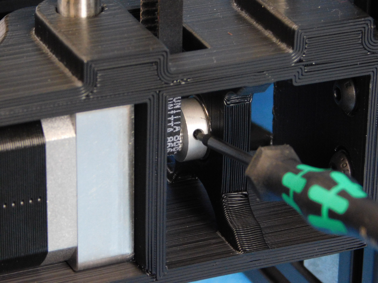
Pulleys: 3 in*lbs
Inspect all printed parts for damage or imperfections.
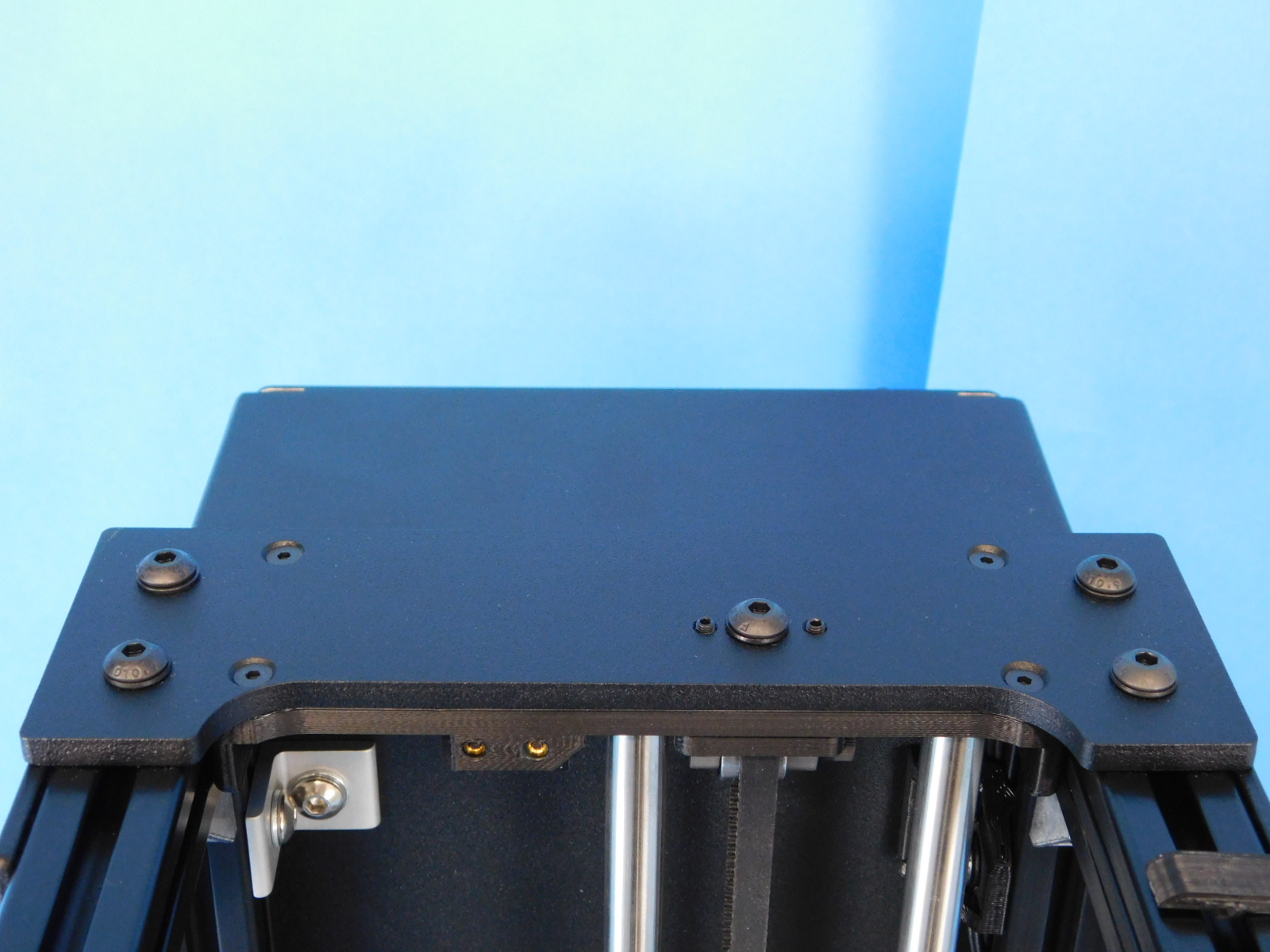
Check the square of the XY axes.


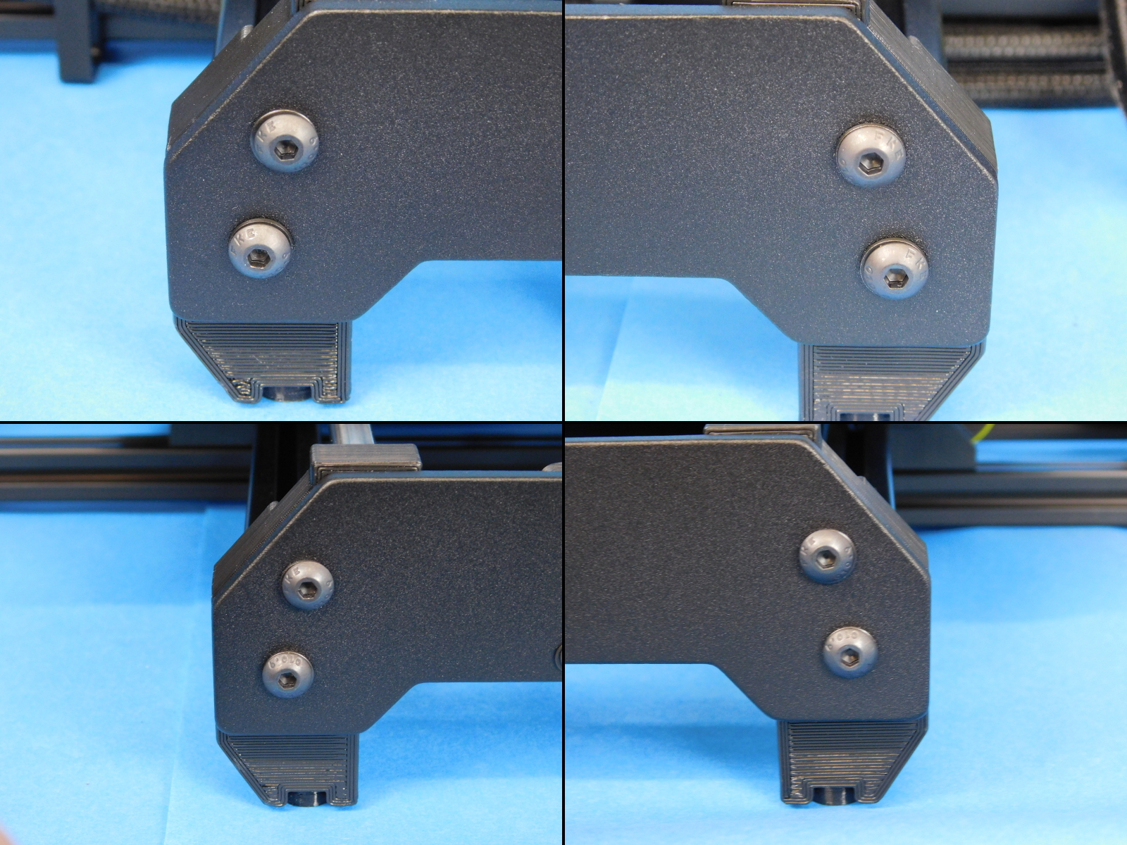
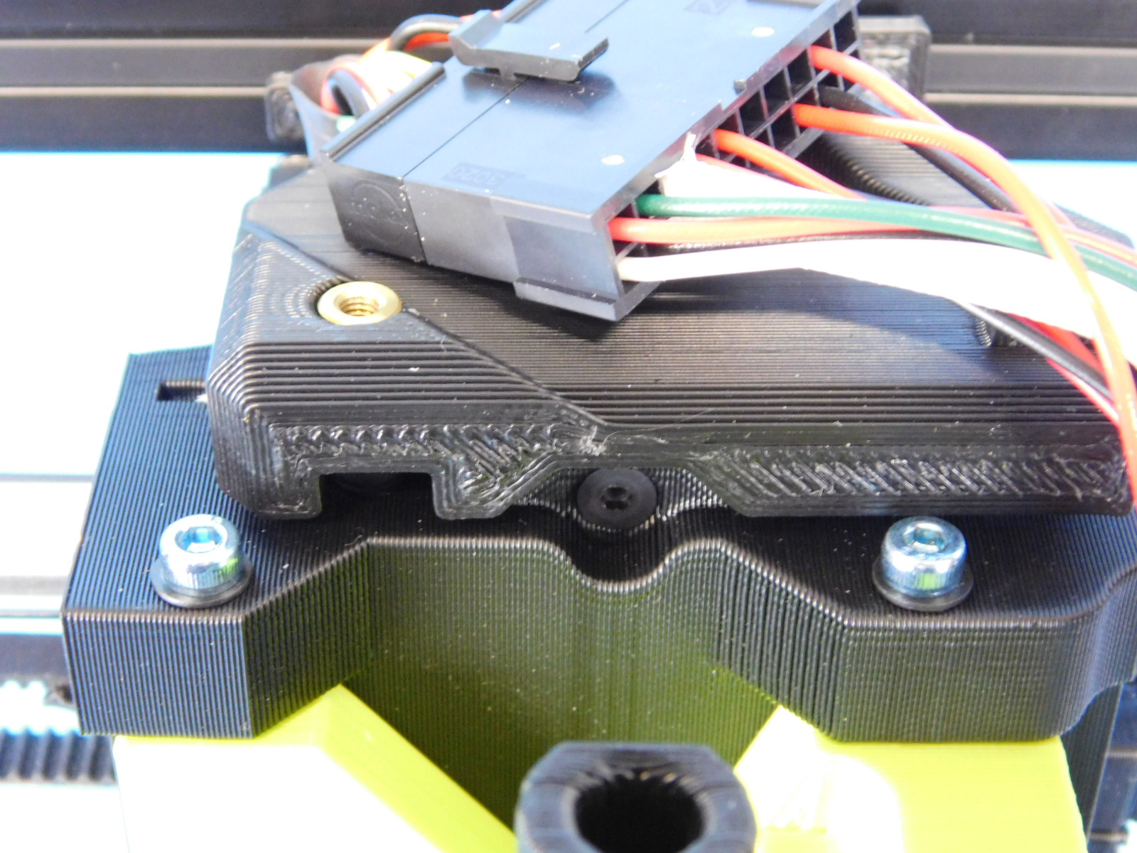


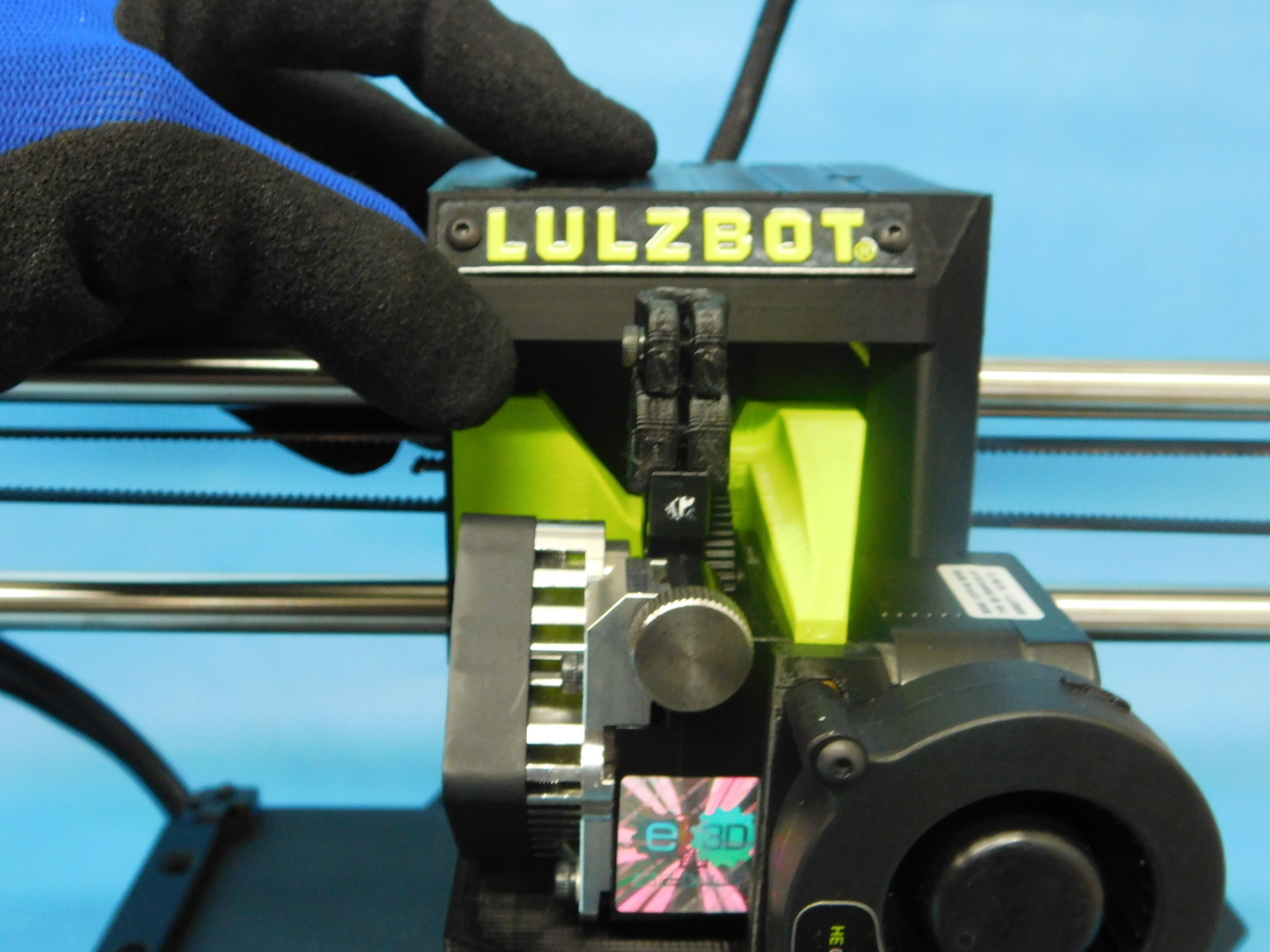
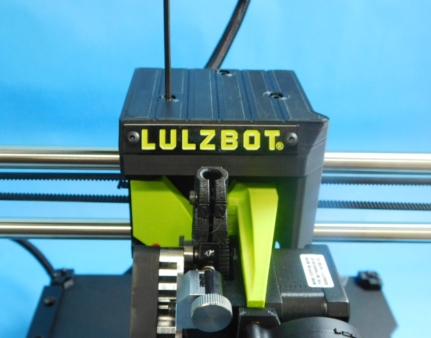
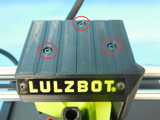
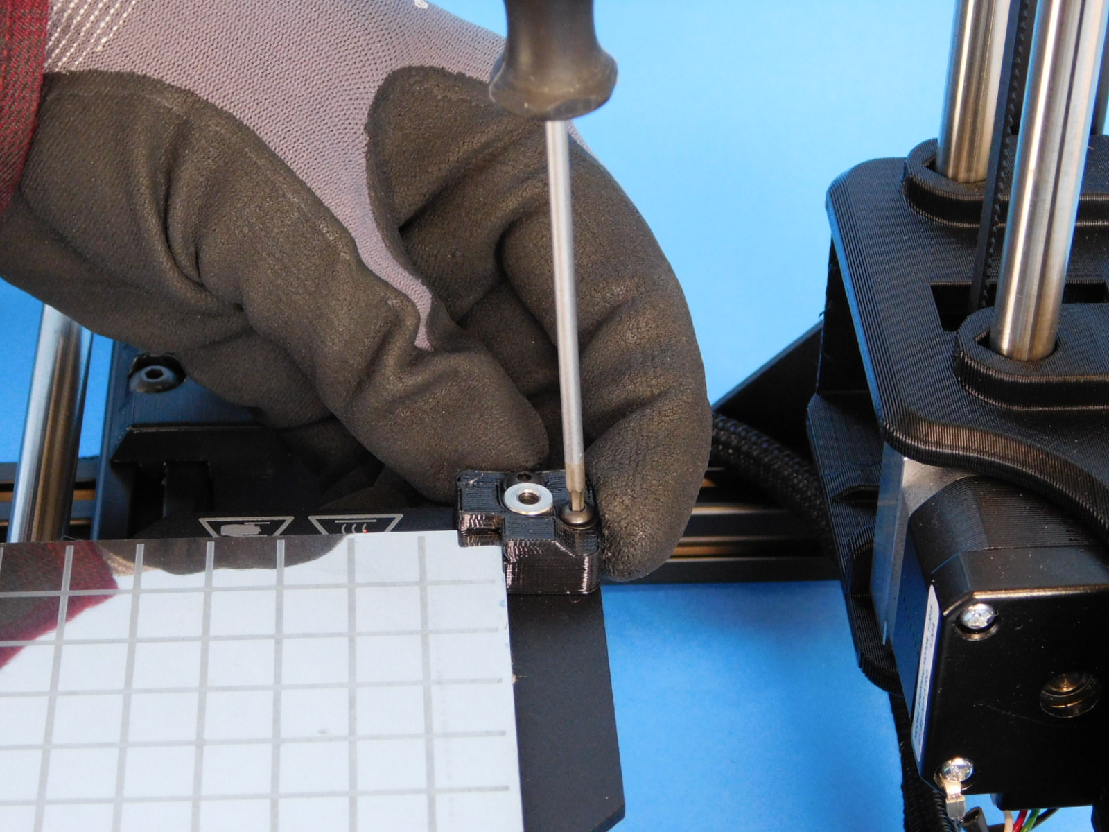
Now that toque specifications have been verified on all reachable fasteners, we can install the extruder cap.
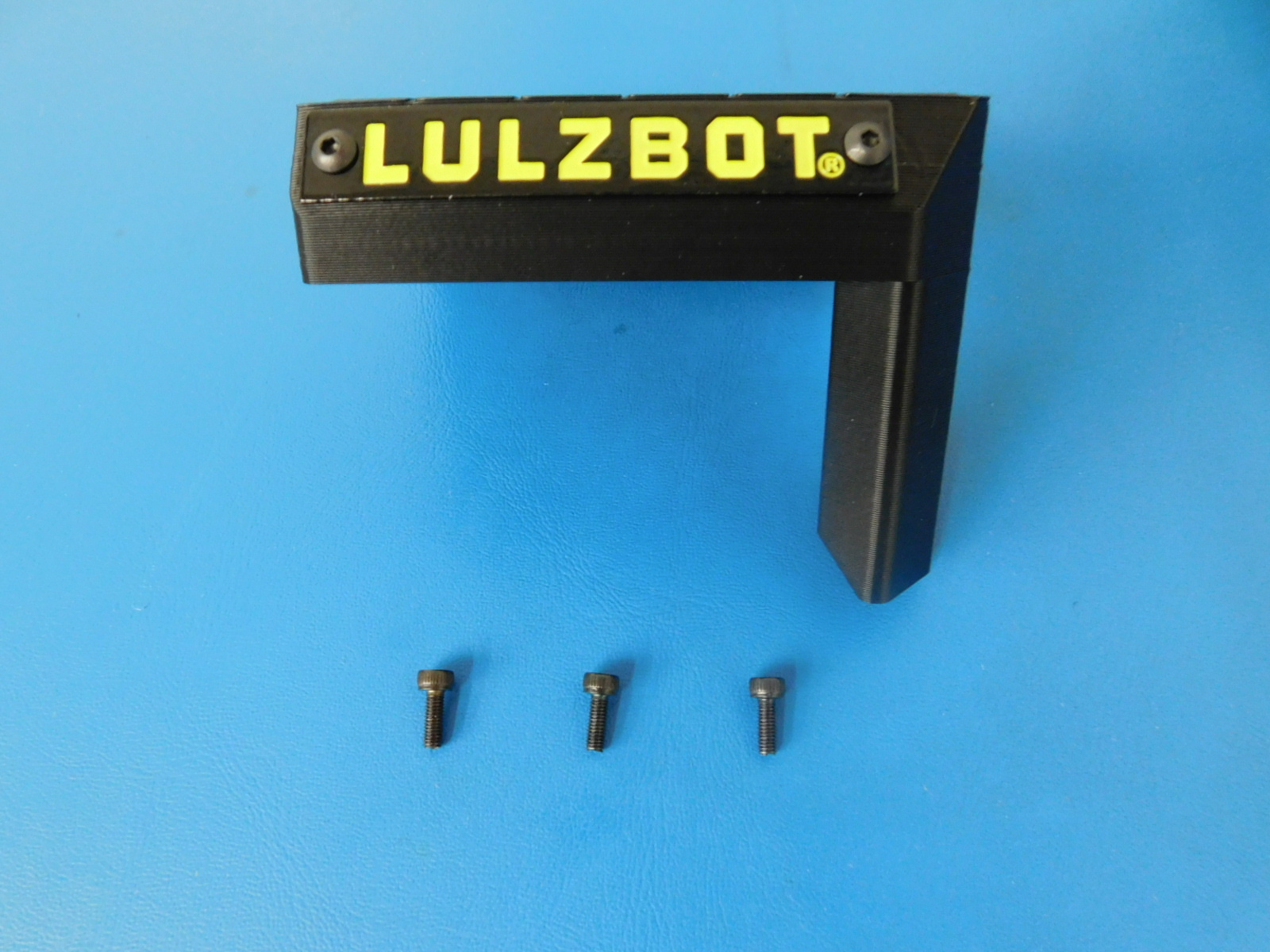
Obtain:
1x- [PP-IS0118] Extruder Cap w/ Plaque
3x- [HD-BT0157] M3x8 SHCS
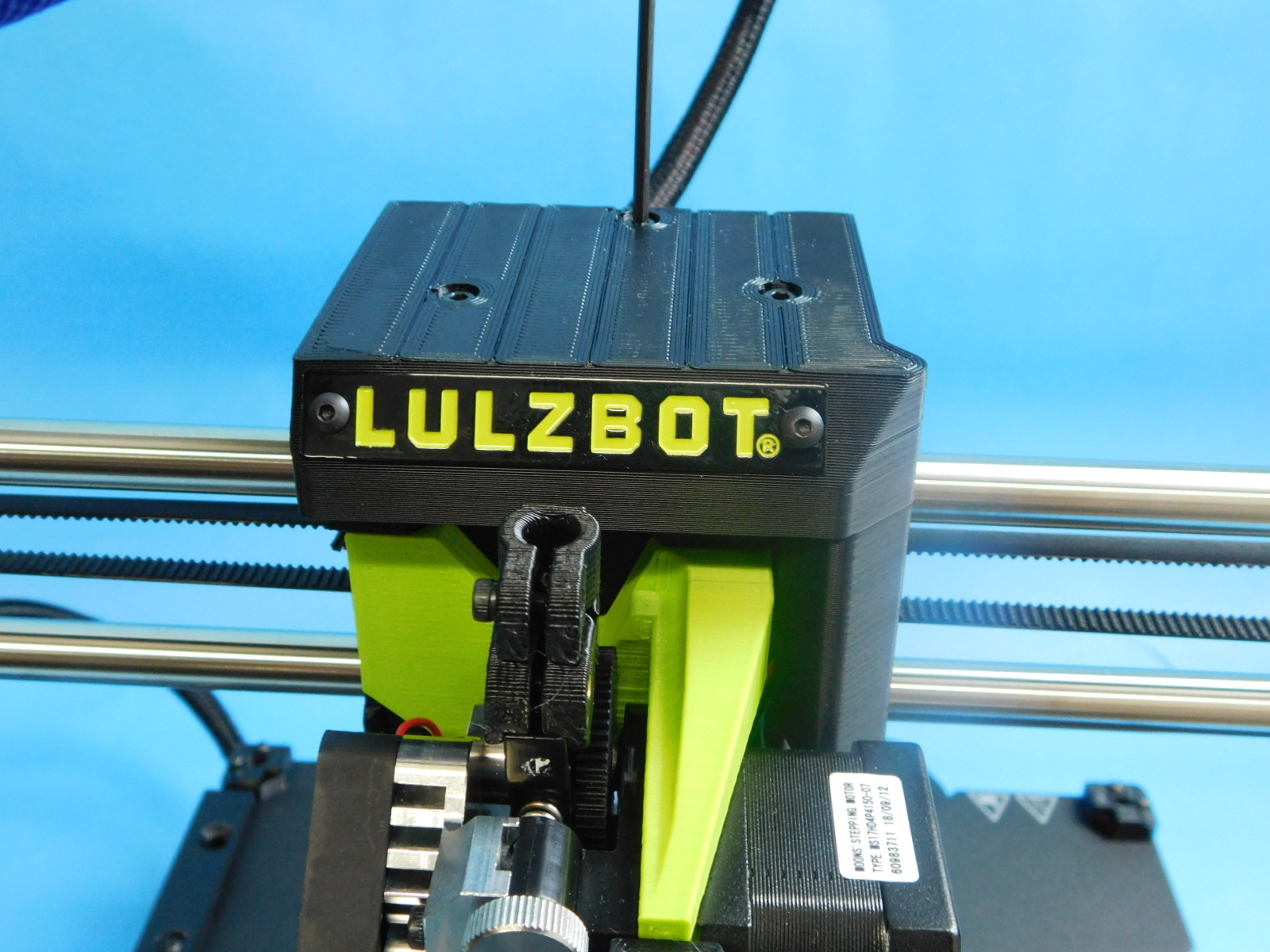
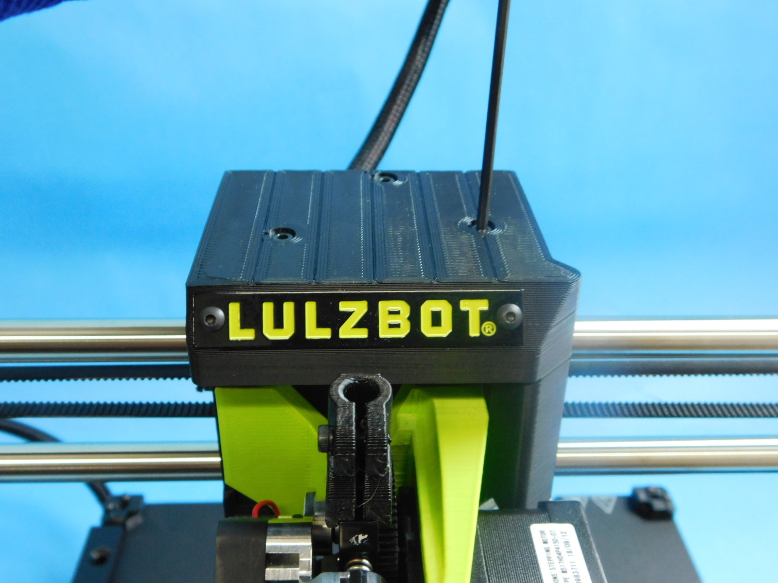
Place the Extruder Cap [PP-IS0118] over the top of the tool head.
Ensure that all cables are inside/under the cap and not sticking out the sides.
Secure using 3x- M3x8 SHCS [HD-BT0157]
No washers
Torque all 3 fasteners to 5in*lbs
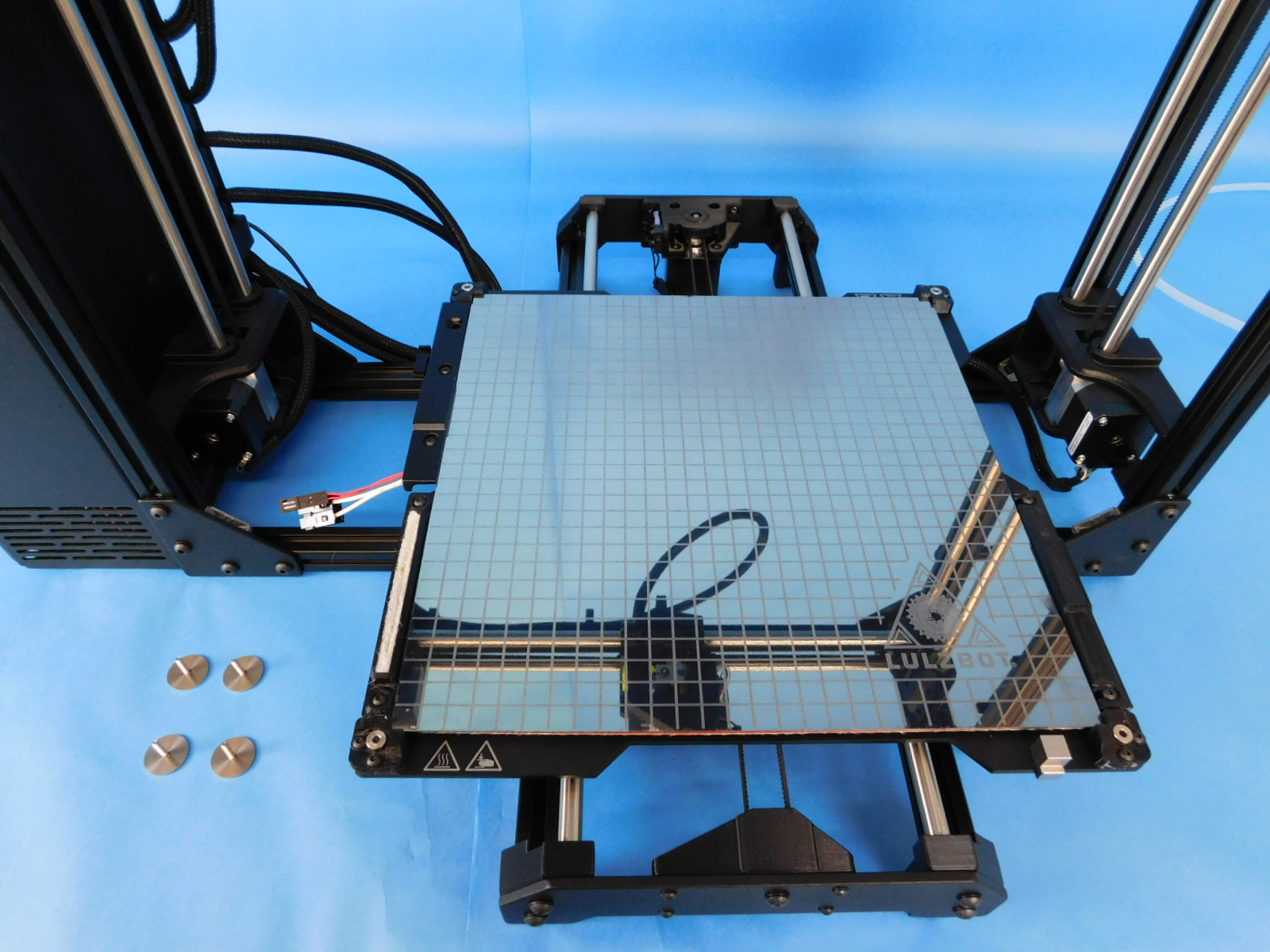
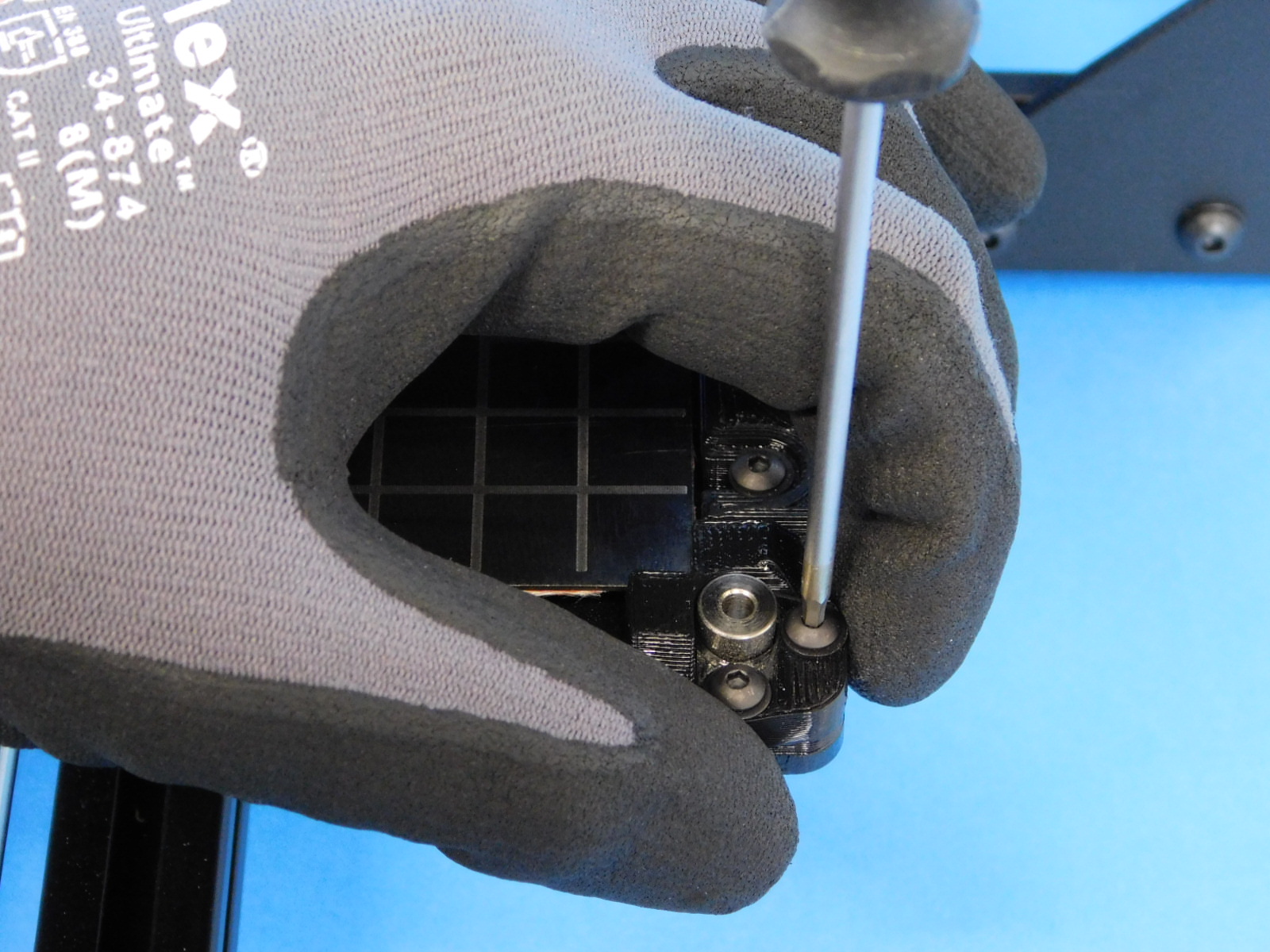
Gather the following materials:
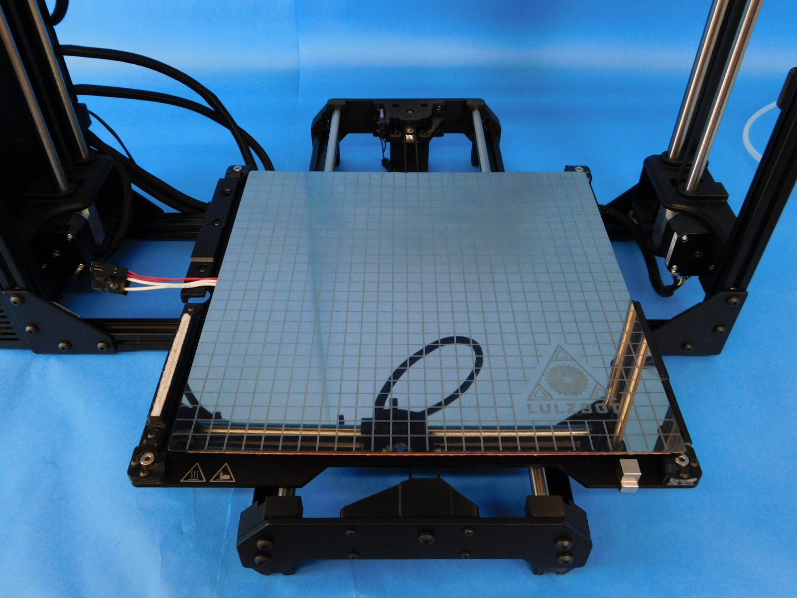
1x- [AS-HB0003] TAZ Glass/PEI Print Surface
1x- [AS-HB0006] TAZ Etched Modular Print Bed Heater
4x- [HD-BT0082] M3x16 Stainless FHCS
4x- [HD-MS0453] (11.11mm) length X (7.94mm) OD X (3.56mm) ID standoffs
4x- [PP-MP0082] Bed Leveling Washer, 303 SST
Place 4x- Bed Spacers [HD-MS0453] inside the bed corners as shown.
Place one Print Bed Heater [AS-HB0006] on top of the assembly with the shiny side up and the wires towards the left.
Tuck the wires from the bed heater under the cable cover as pictured.
Slide the bed to the left so that all four corners of the bed heater rest inside the flexible bed corners.
Tighten both screws on all four bed corners until the end of each screw is flush with the bottom of the bed plate.
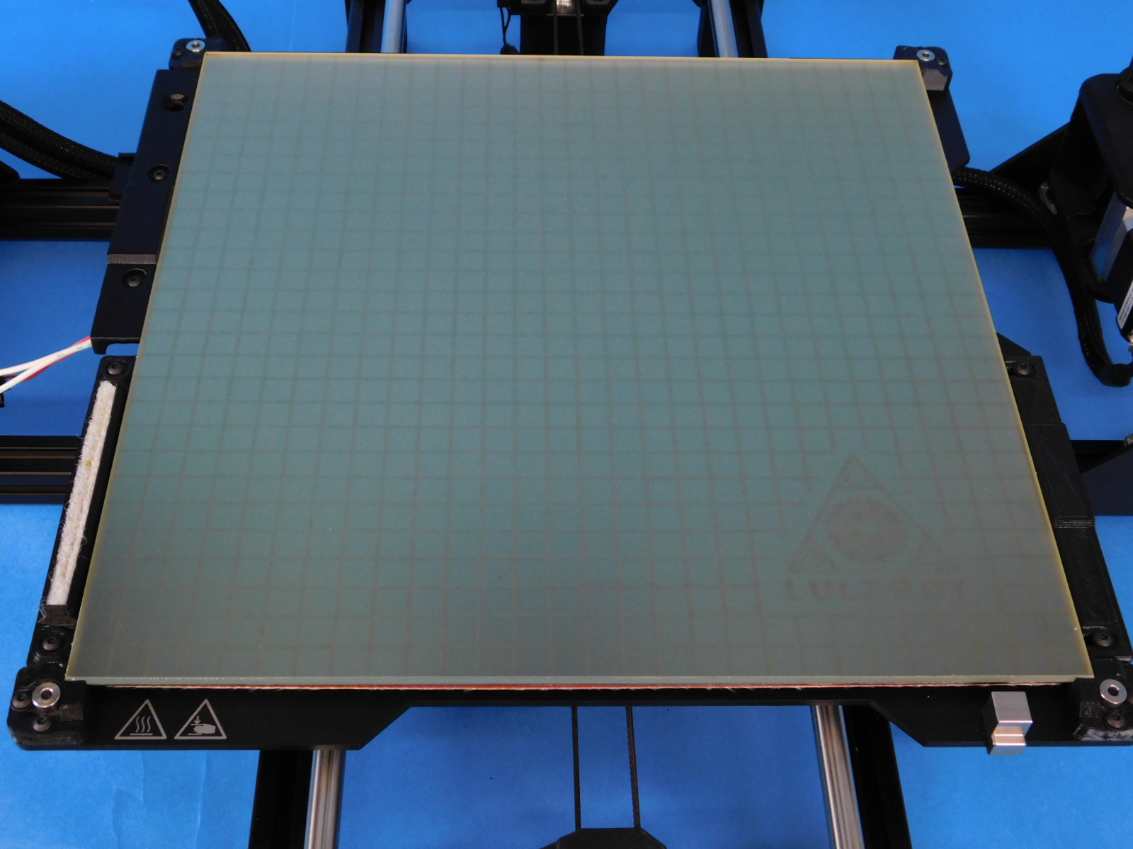
Lay one TAZ Glass/PEI Print Surface [AS-HB0003] over the print bed heater as pictured.
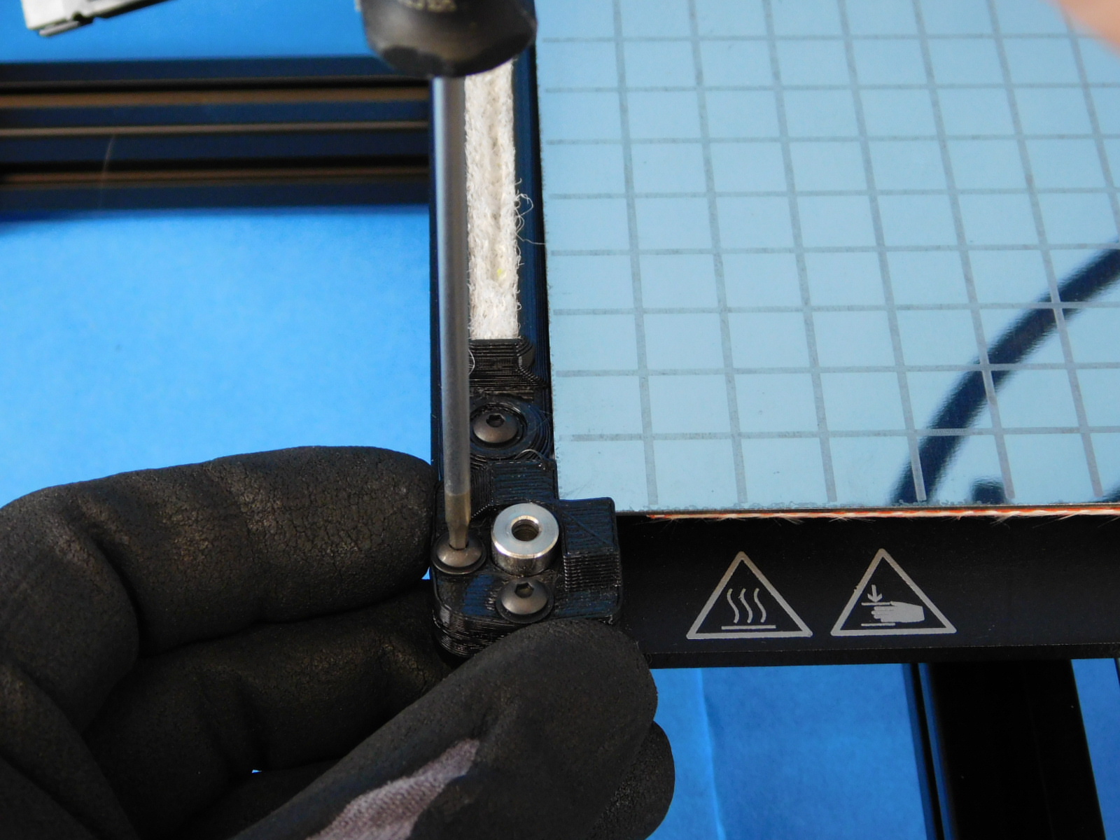
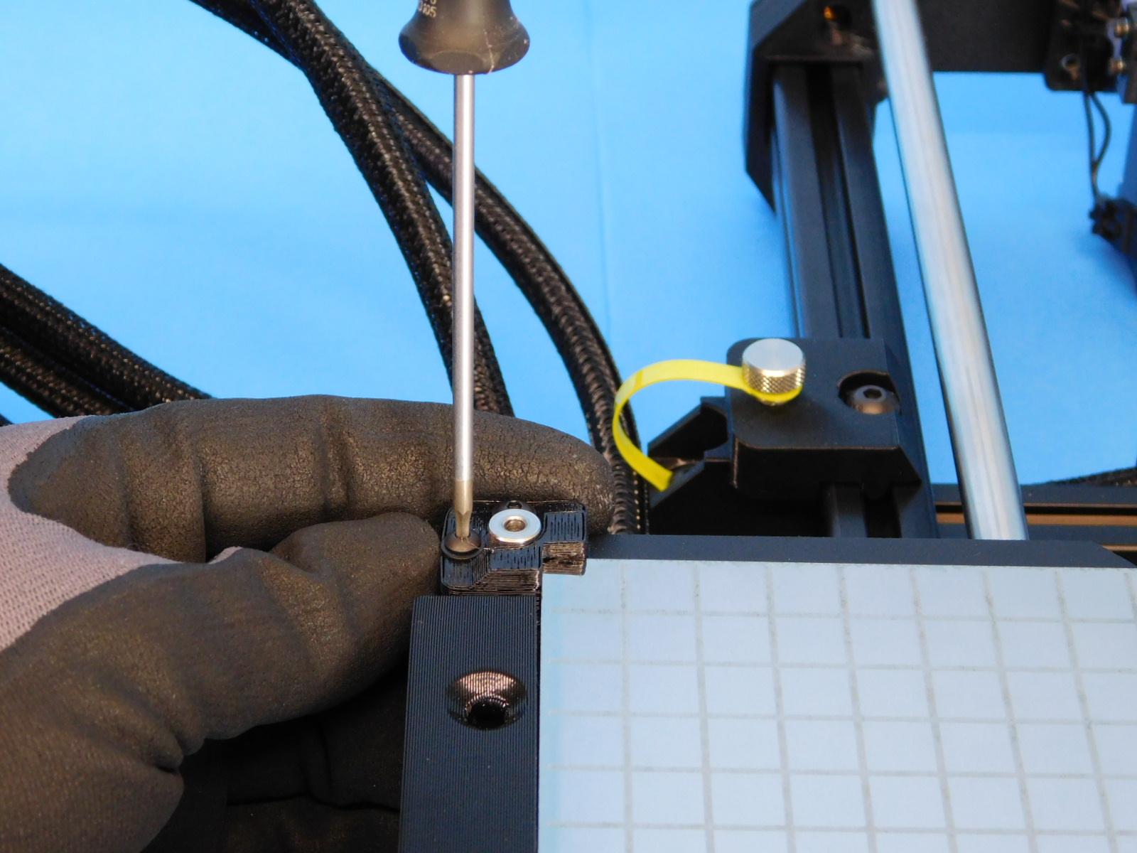
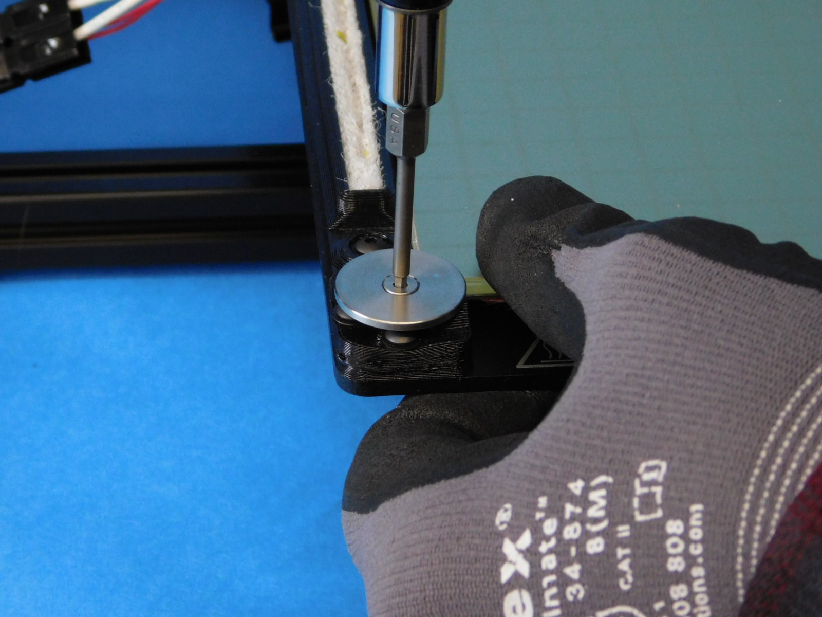
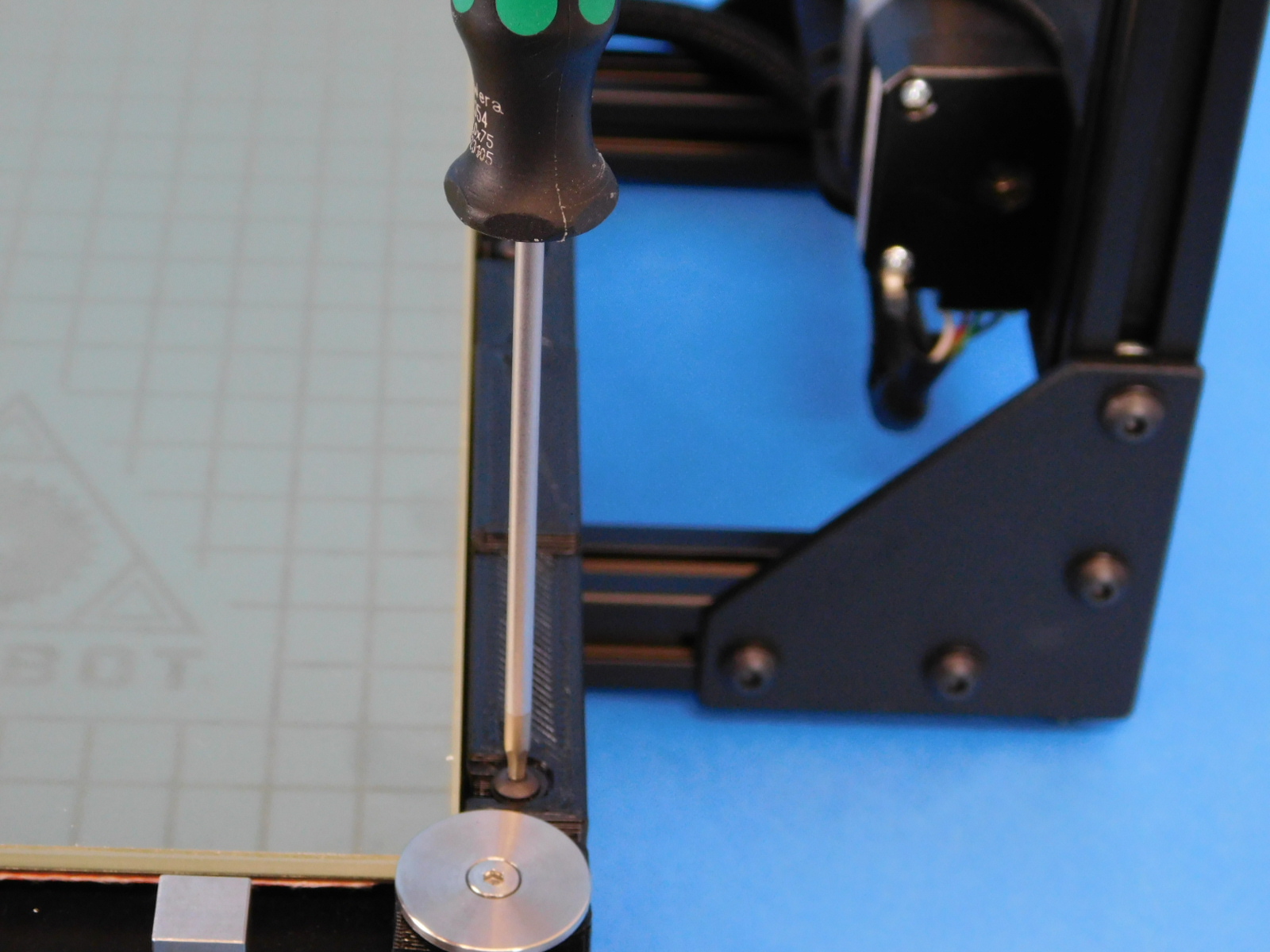
Install each of the four bed leveling washers [PP-MP0082] to the bed corners using 1x- M3x16 Stainless FHCS [HD-BT0082] for each.
Press down on the glass near the bed corner to be tightened, this ensures the bed leveling washers will sit flat.
Follow the sequence shown
Torque all four fasteners to 5in*lbs
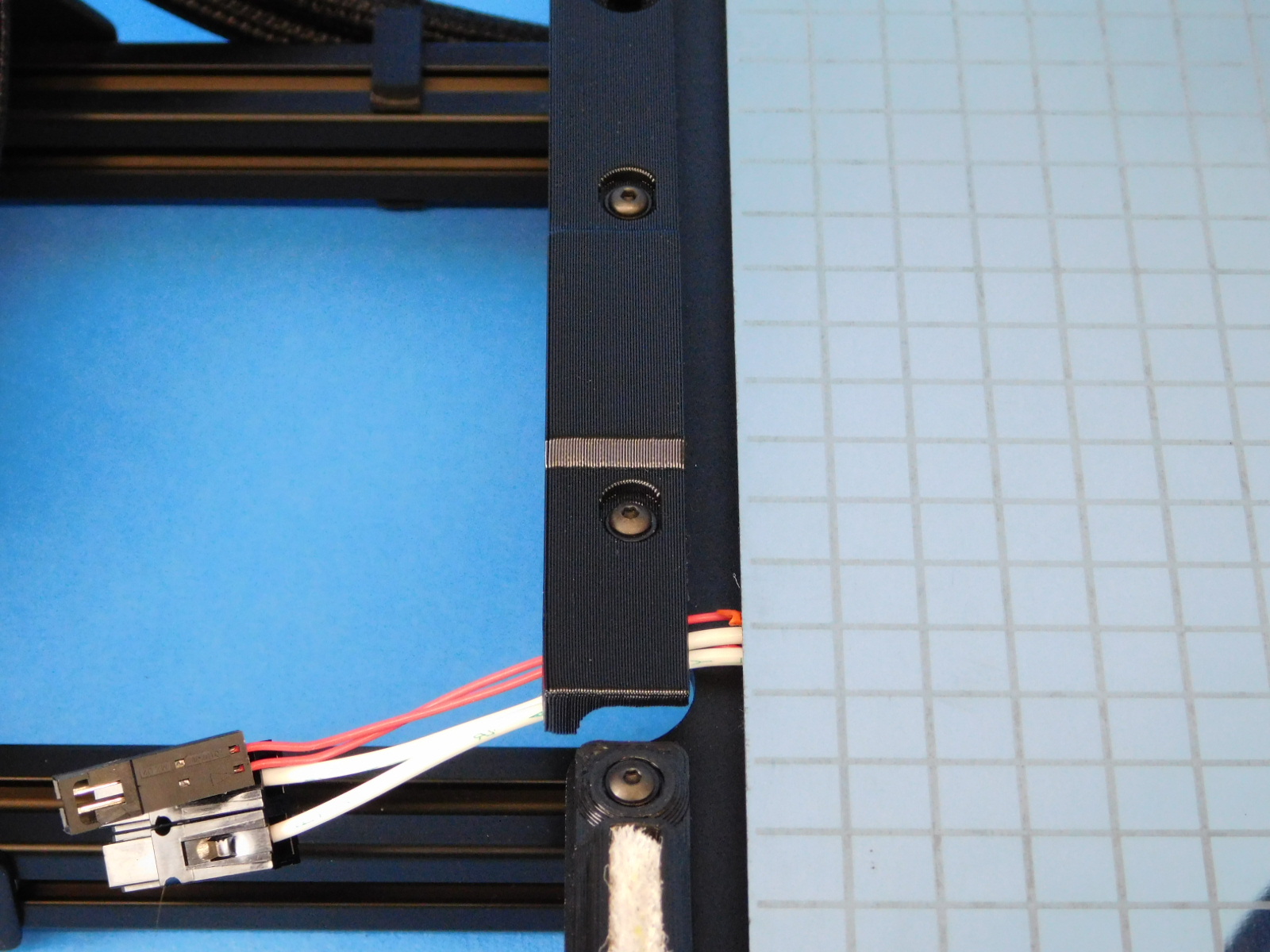


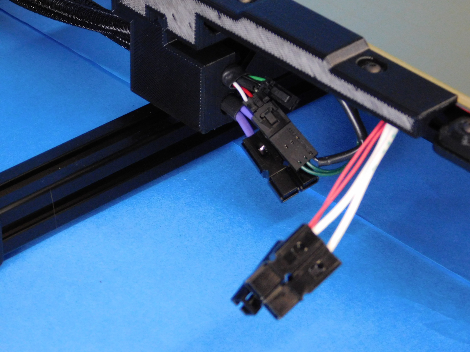
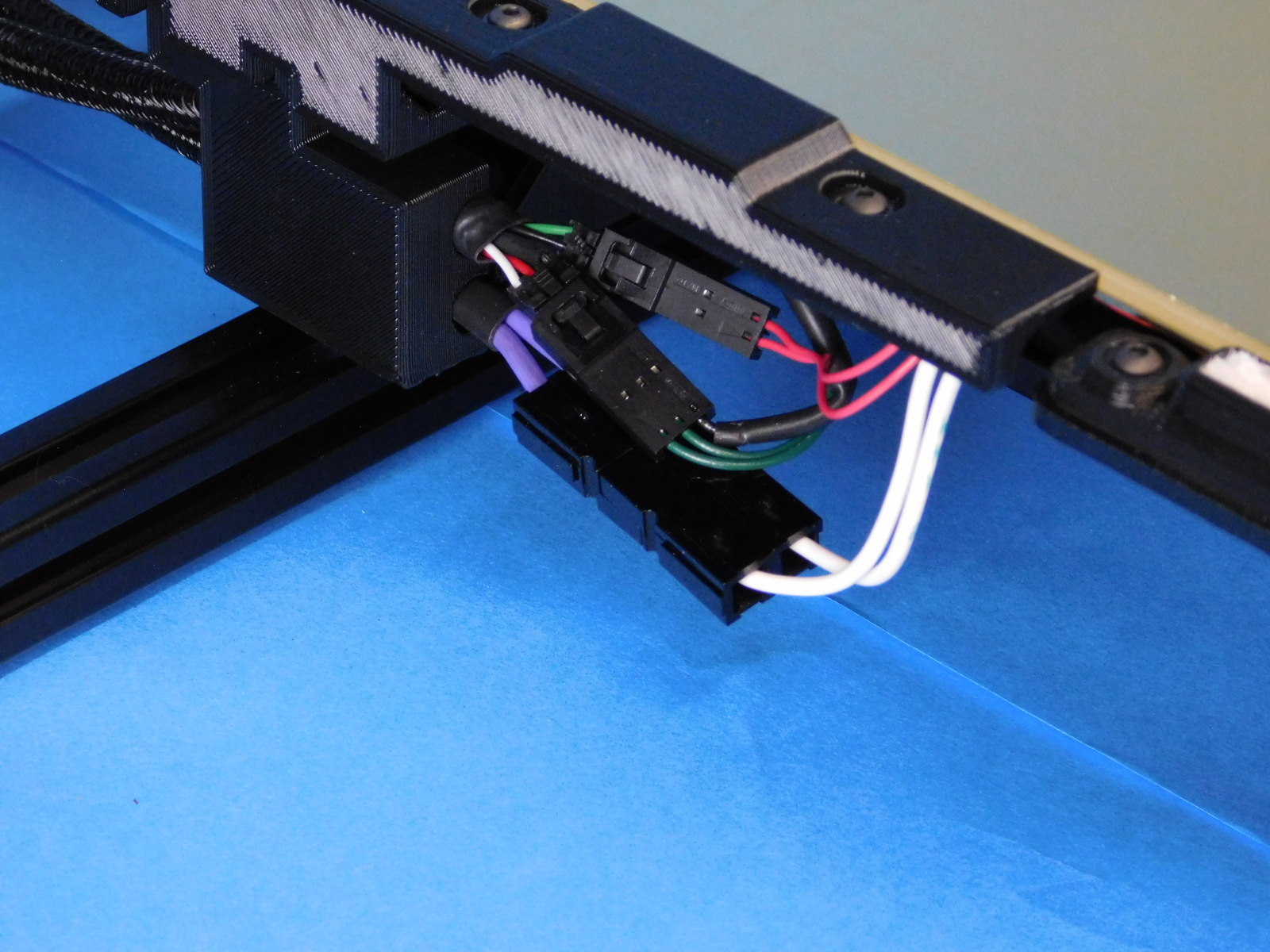
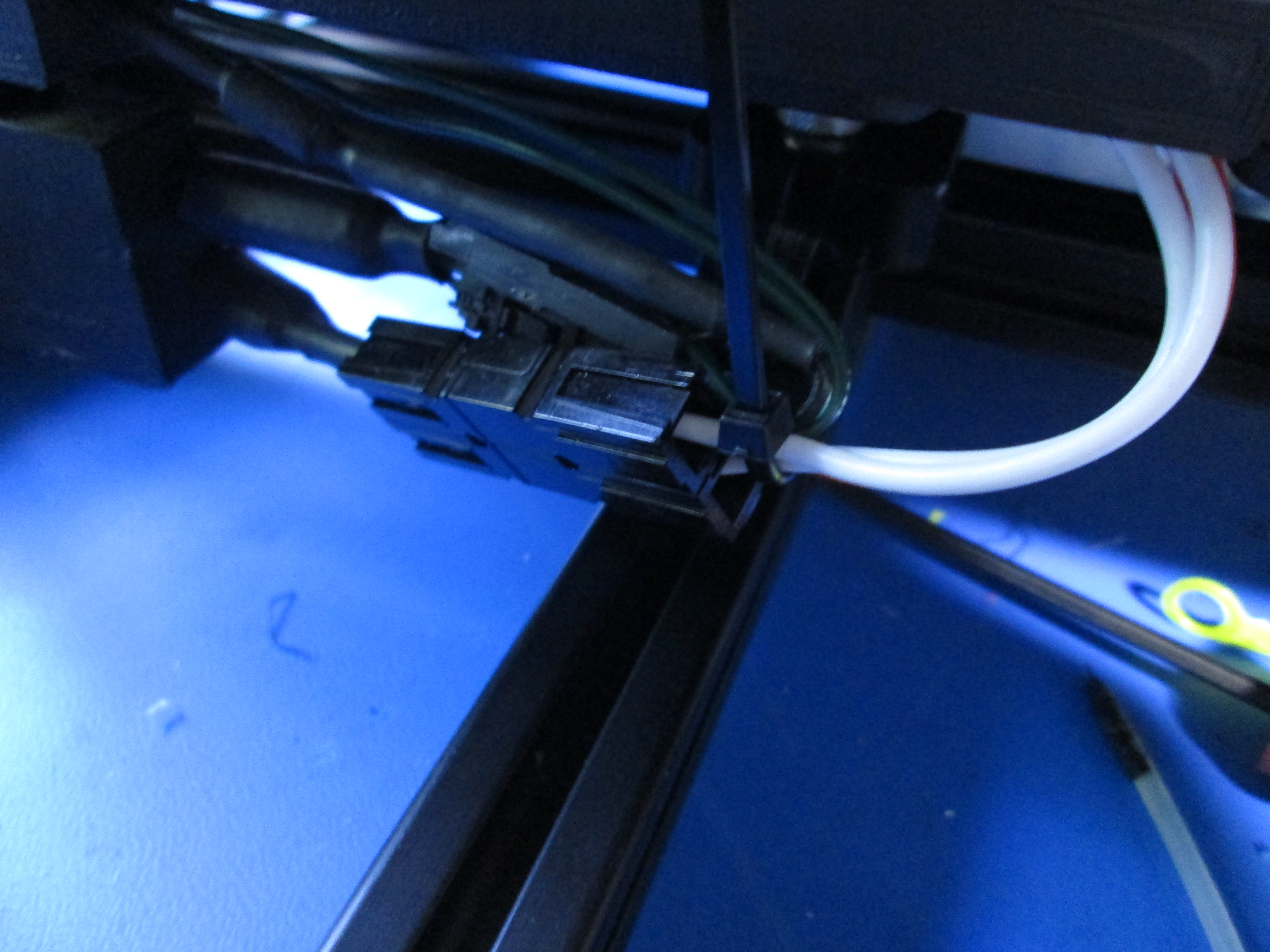
Ensure proper connection between all 3 connectors under the bed;
Ground – 3 pin molex connector
Thermistor – 2 pin molex connector
Bed Power – 2 position Anderson PowerPole connector
Use one zip tie [HD-MS0058] to secure all of the wires together as shown. Cut excess zip tie flush with the latch
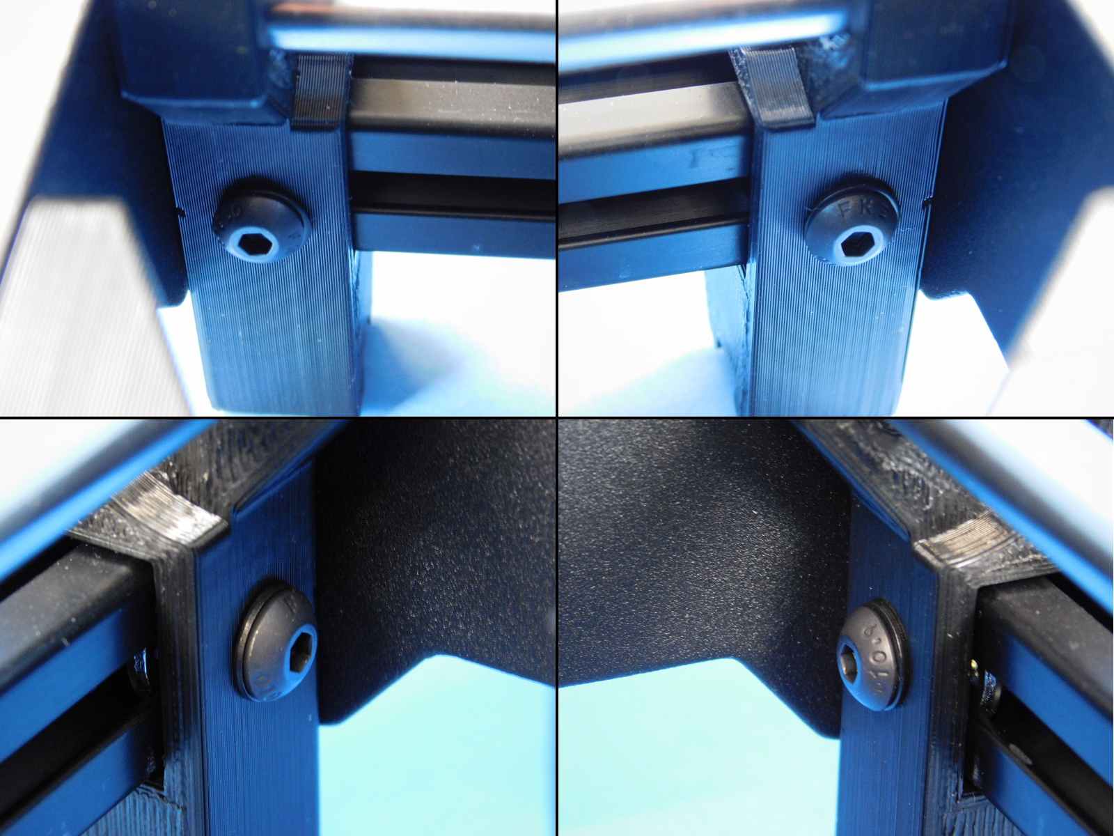
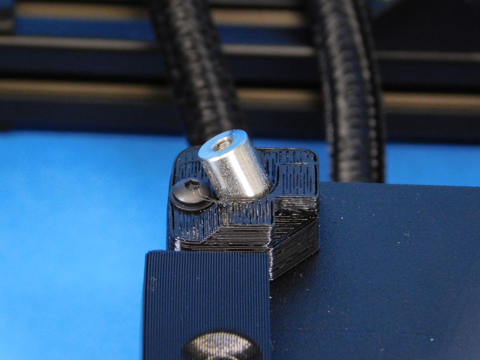
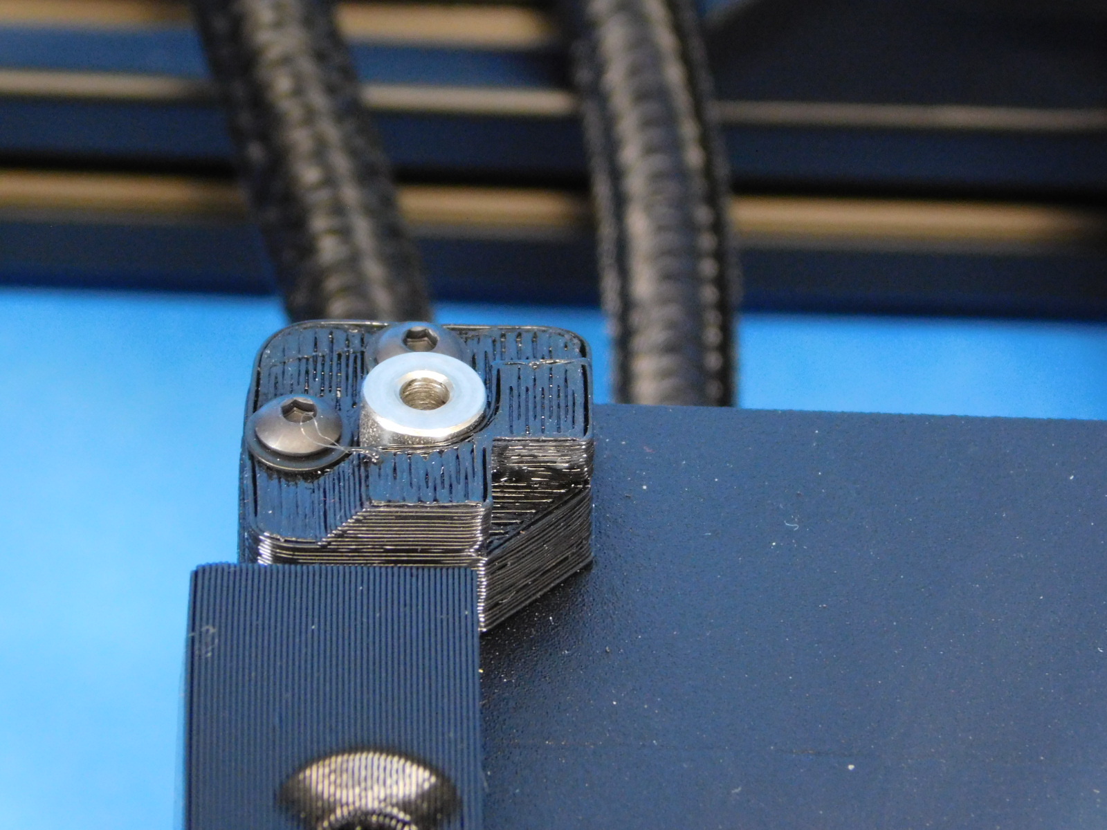
Both the wiper mount and the auxiliary bed mount cover are left loose until the bed is fully seated; torque all 4 fasteners to 5in*lbs


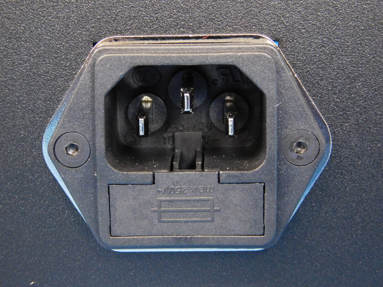
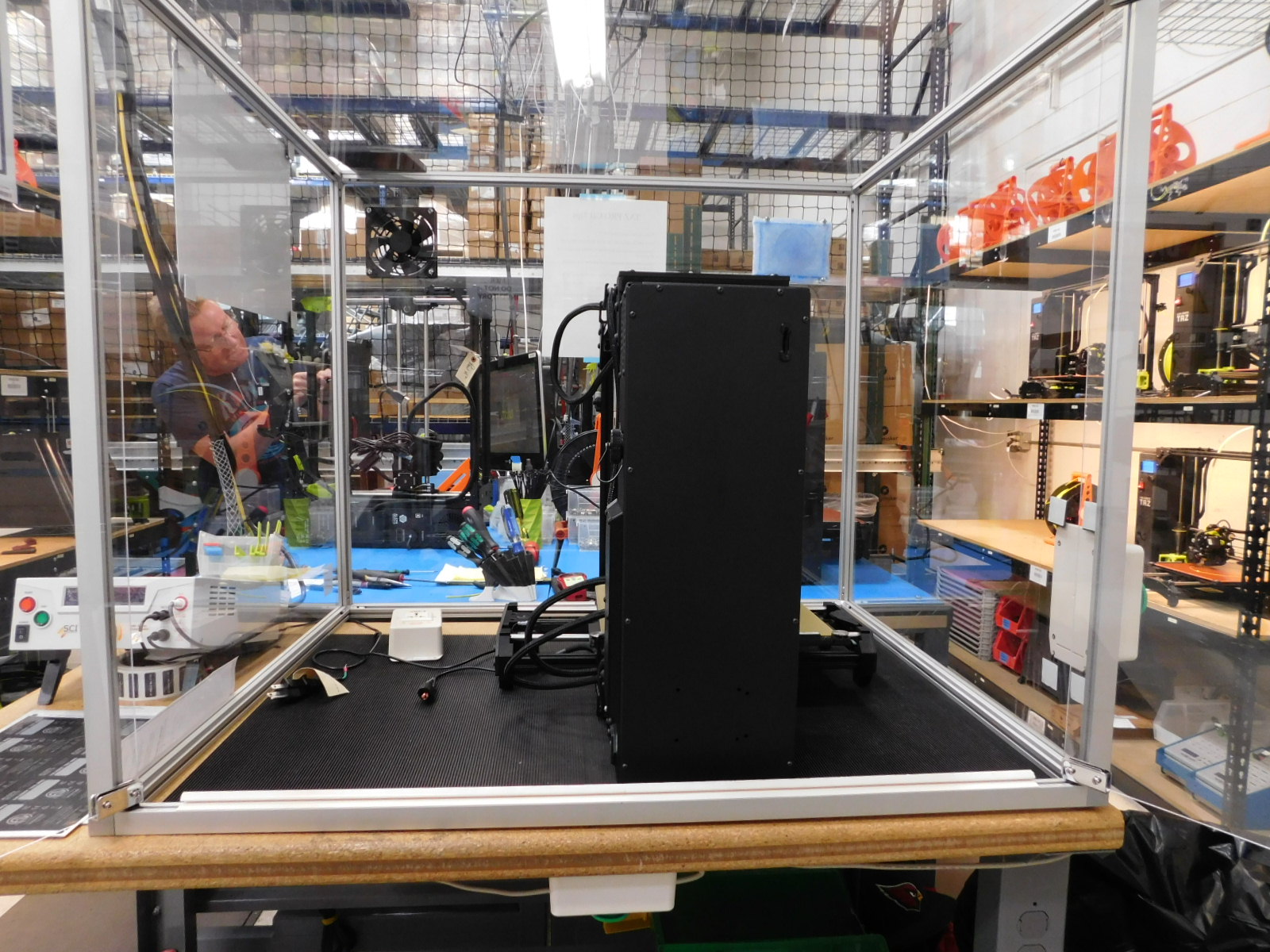
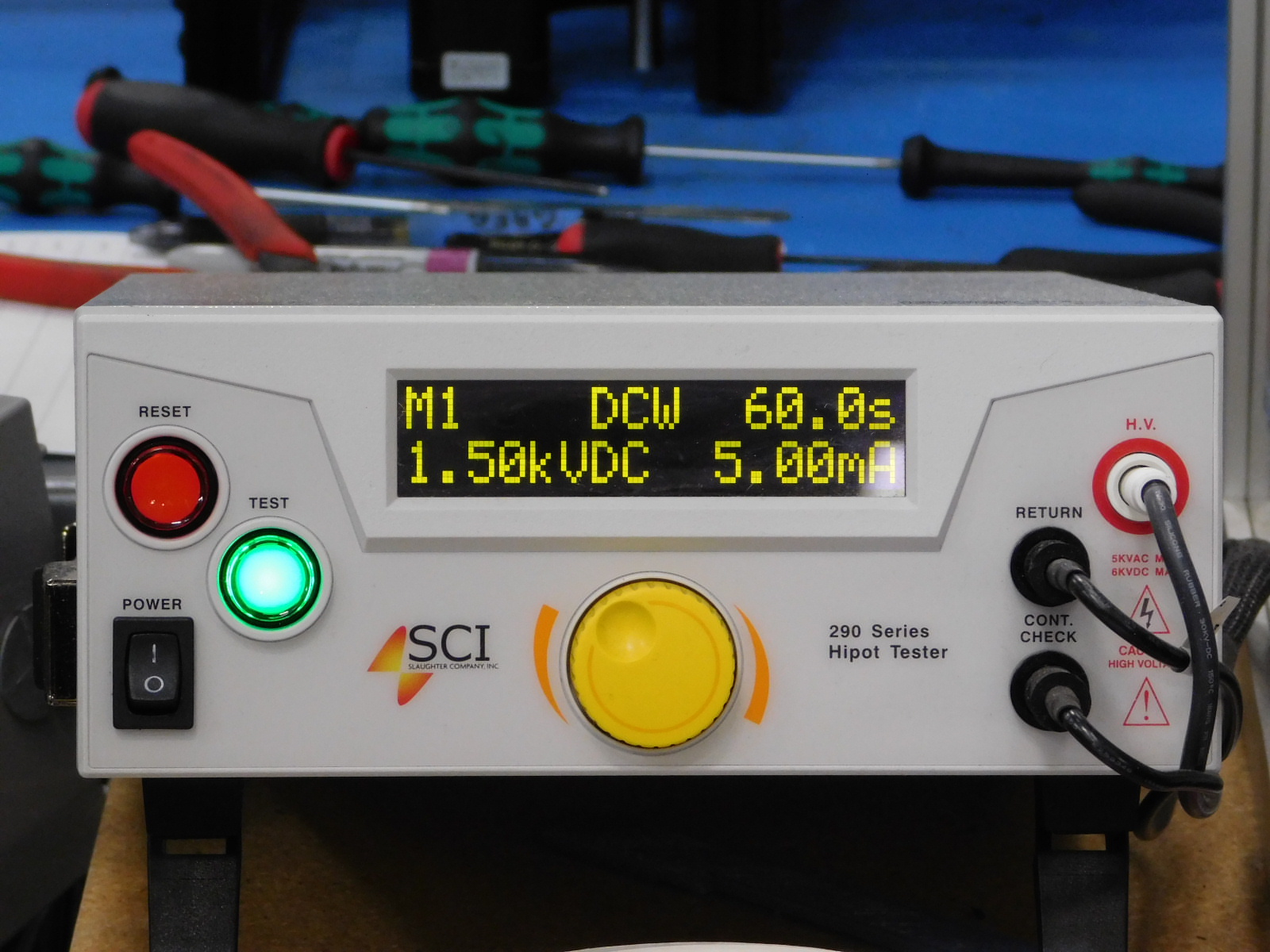
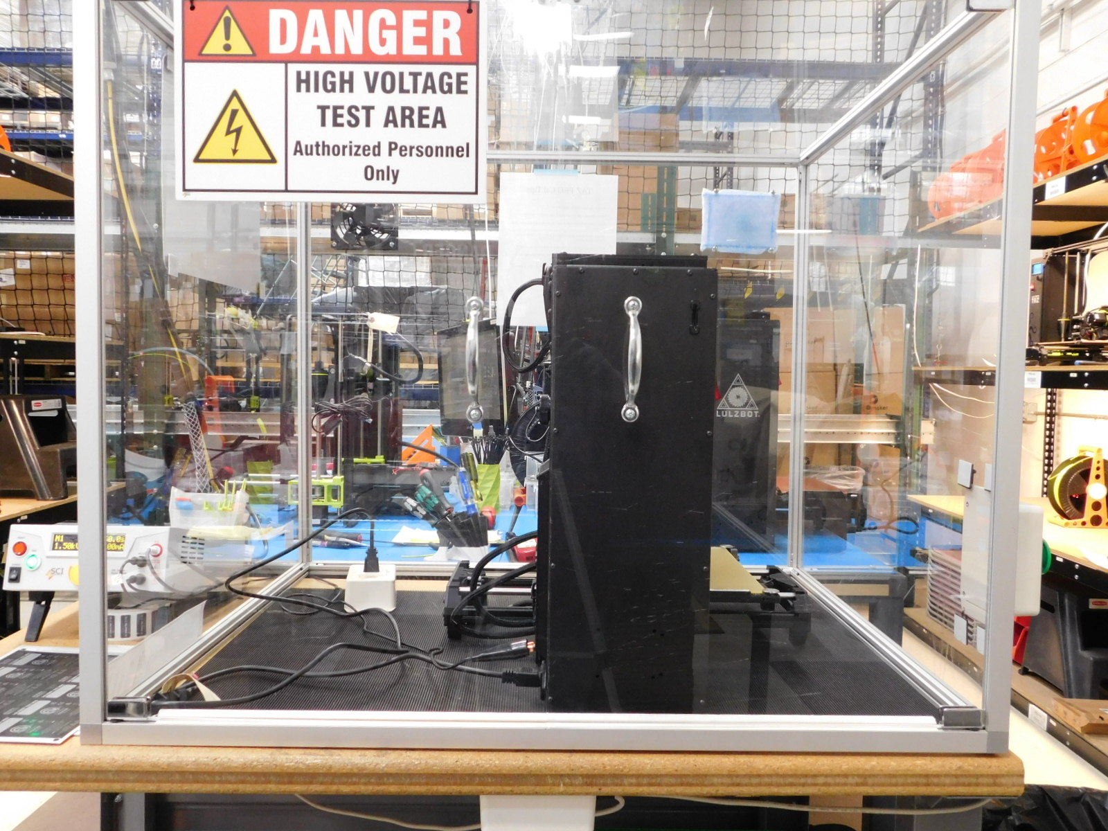
Hi-Pot Testing may not occur before the unit is fully assembled
Carefully place the unit inside of the Hi-Pot Testing safety box
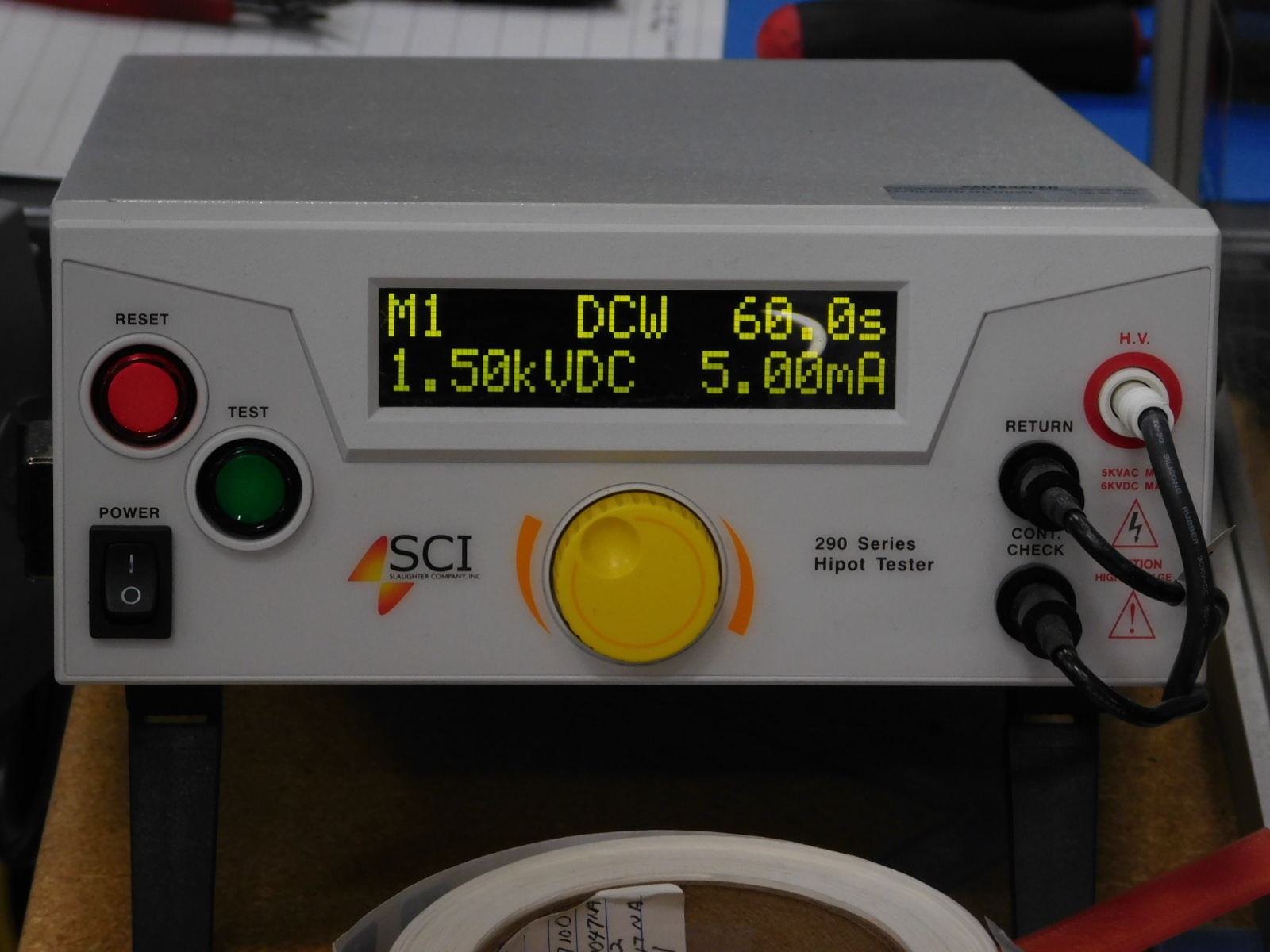
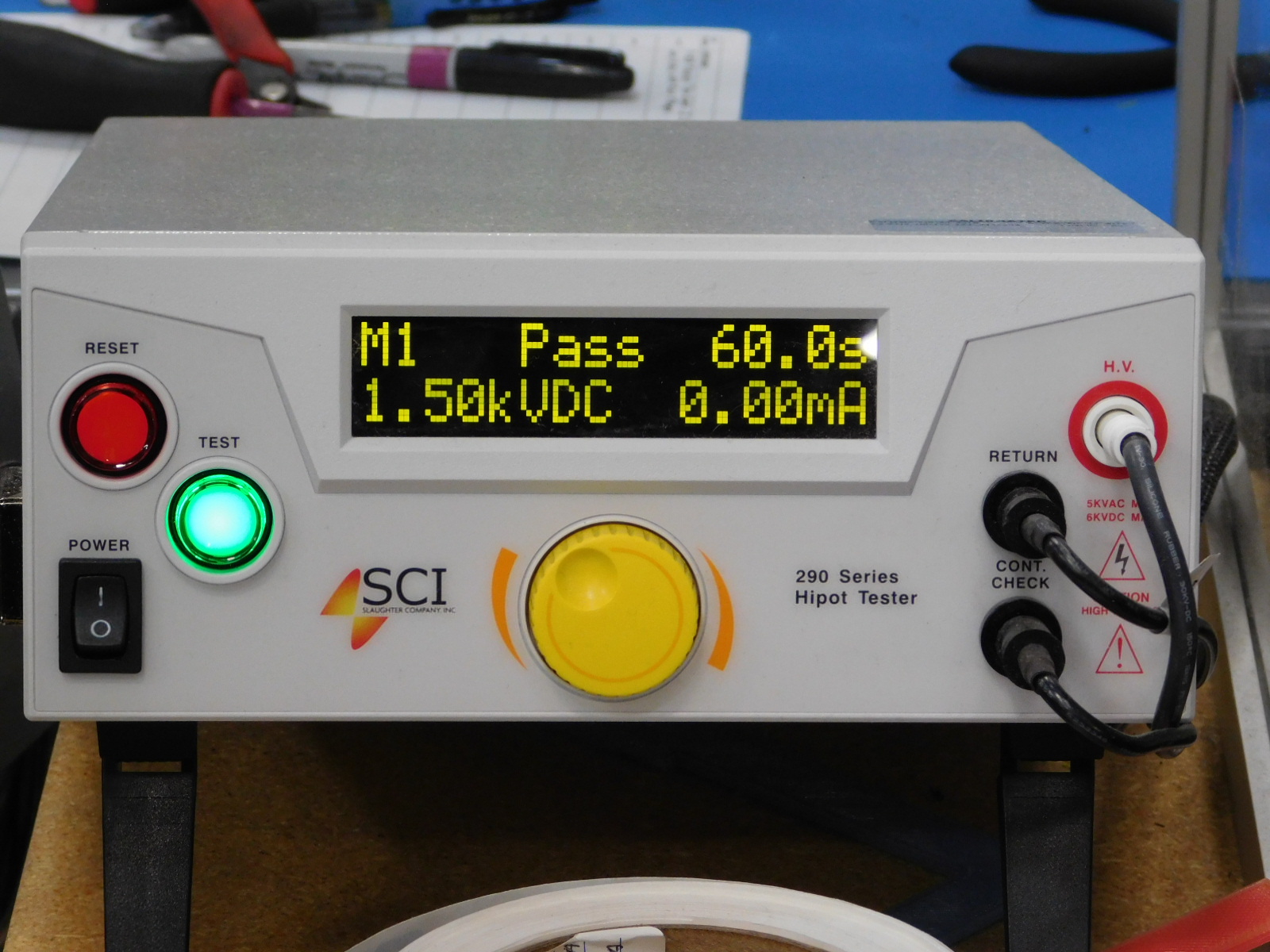
Power on the Hi-Pot testing unit
For North American shipments:
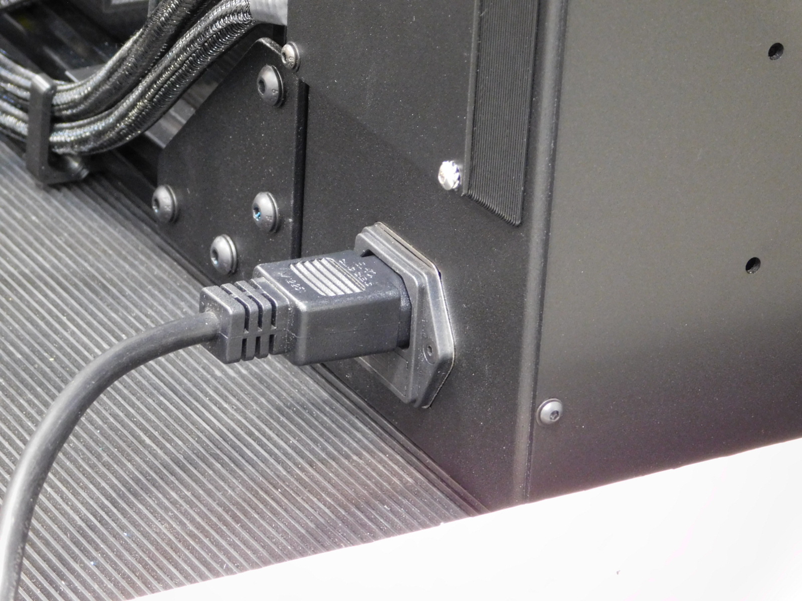
Obtain a North American power cable [EL-CA0030] and connect it to the printer, this will be the cable shipped with the printer.
Plug the other end of the cable into the testing units receptacle.
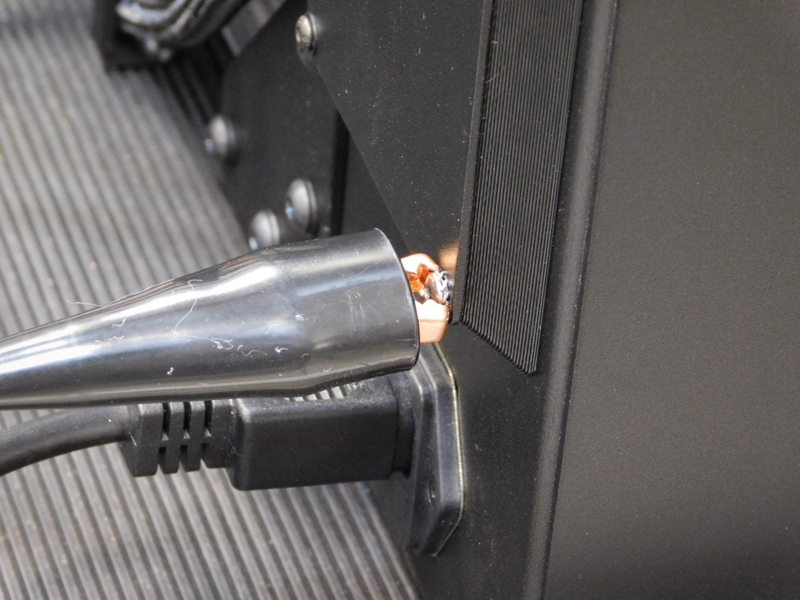
Connect the Hi-Pot testing units gator clip securely to the stainless fastener at the rear of the chassis; bottom of the interconnect housing cover.
The green light on the Hi-Pot tester should now be illuminated, indicating proper continuity of the ground circuit.
IF THE GREEN LIGHT FAILS TO ILLUMINATE, THE PRINTER HAS FAILED THE TEST
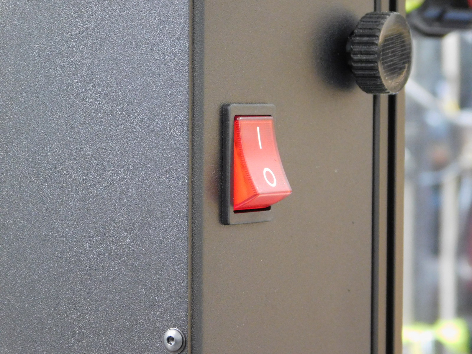
Flip the printers power switch to the “ON” position and close the doors of the safety box
Starting the test:
**ENSURE THERE IS NO PHYSICAL HUMAN CONTACT WITH THE PRINTER OR HI-POT TESTER
WITH BOTH HANDS, ENGAGE THE INTERLOCK BY PRESSING THE BUTTON TO YOUR LEFT WITH YOUR LEFT HAND AND THE BUTTON TO YOUR RIGHT WITH YOUR RIGHT HAND TO BEGIN THE TEST
HOLD BOTH INTERLOCK BUTTONS UNTIL THE TEST IS COMPLETE
ENSURE THERE IS NO PHYSICAL HUMAN CONTACT WITH THE PRINTER OR HI-POT TESTER DURING THE ENTIRE DURATION OF THE TEST**
If the Hi-Pot test unit reports "PASSED" ensure this state is recorded on the QA sheet to be sent with the printer and forward the printer (with the tested cable) to the next available calibrator.
A "FAIL" report from the Hi-Pot tester indicates a problem with the printers power supply or grounding circuit. Refer the machine to MER for proper diagnosis.


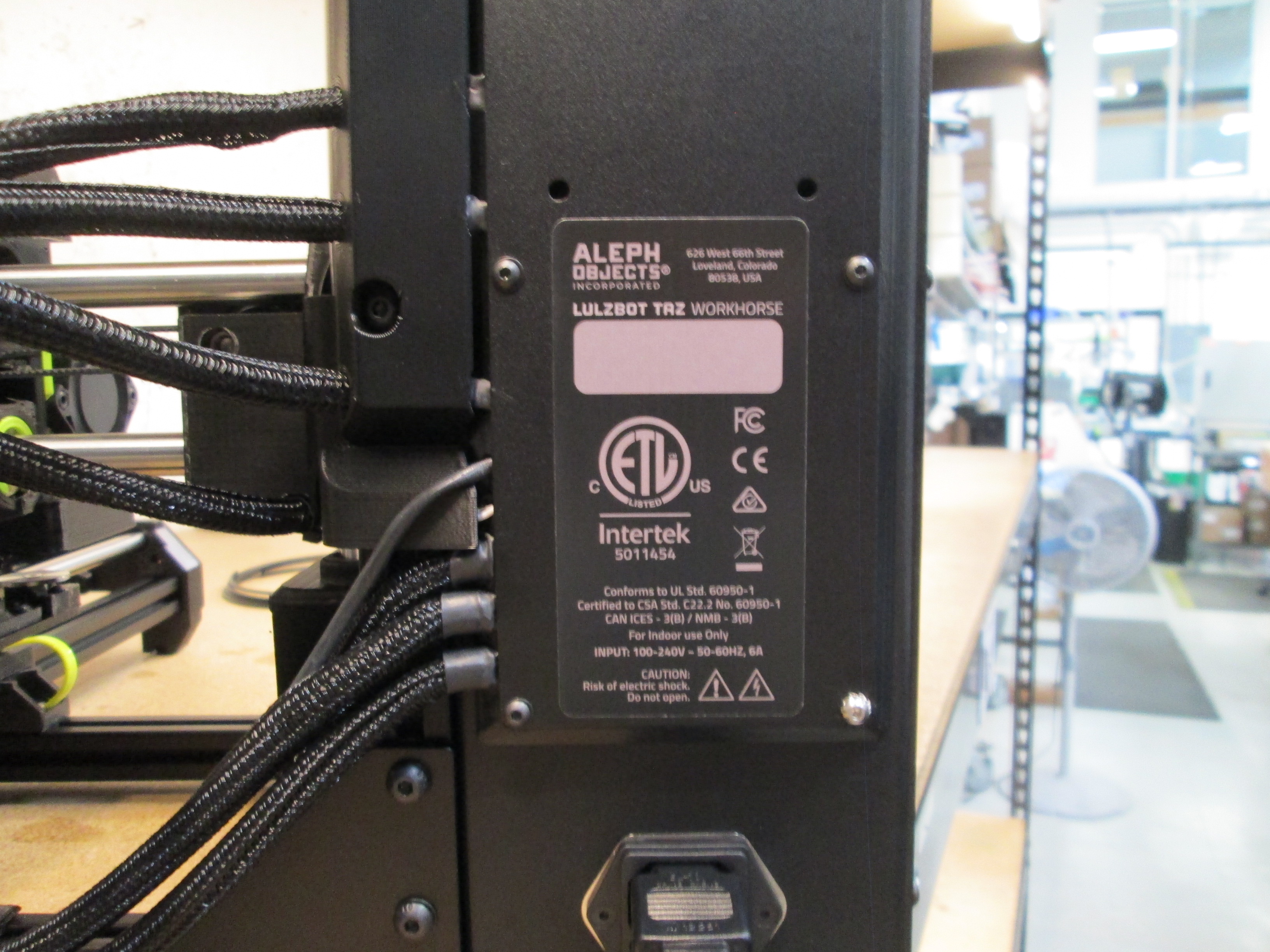
Materials required:
1x- [DC-LB0189] LulzBot TAZ Workhorse Edition Certification Sticker
This sticker is tamper evident, so you only get one chance
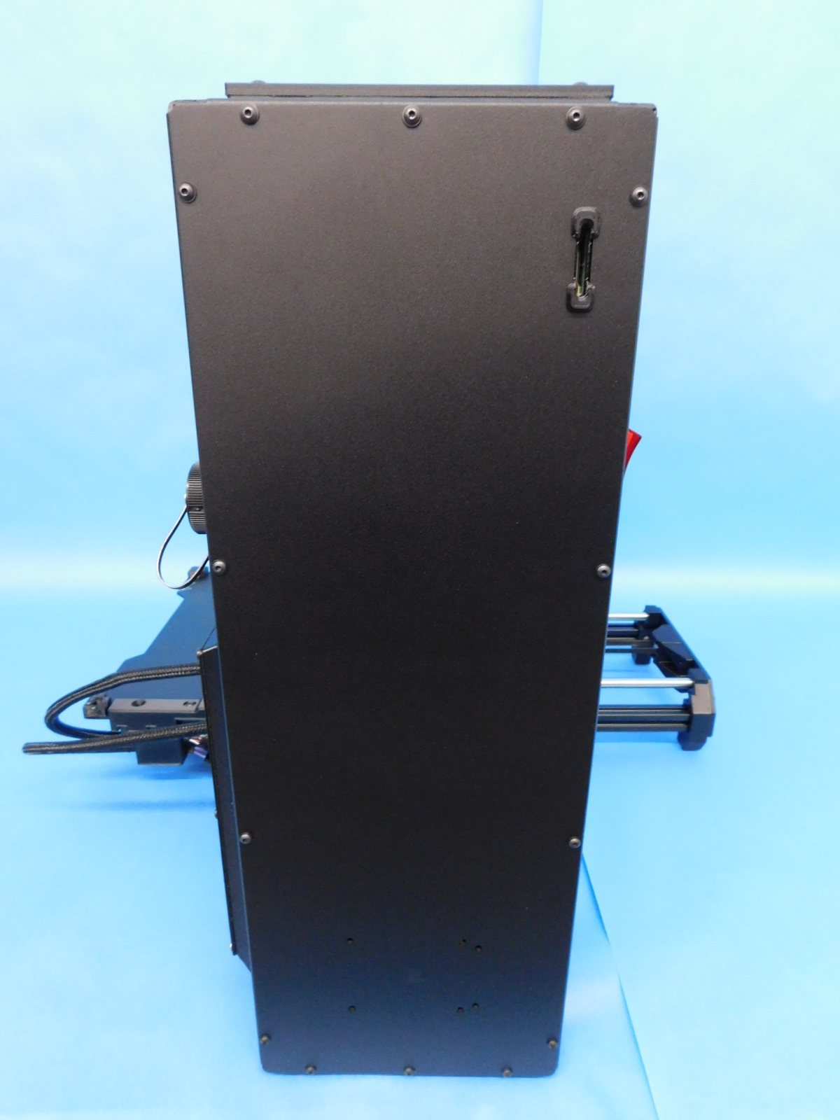
Line up and apply a Certification Sticker [DC-LB0189] to the rear of the electronics case as pictured.
Verify the following:
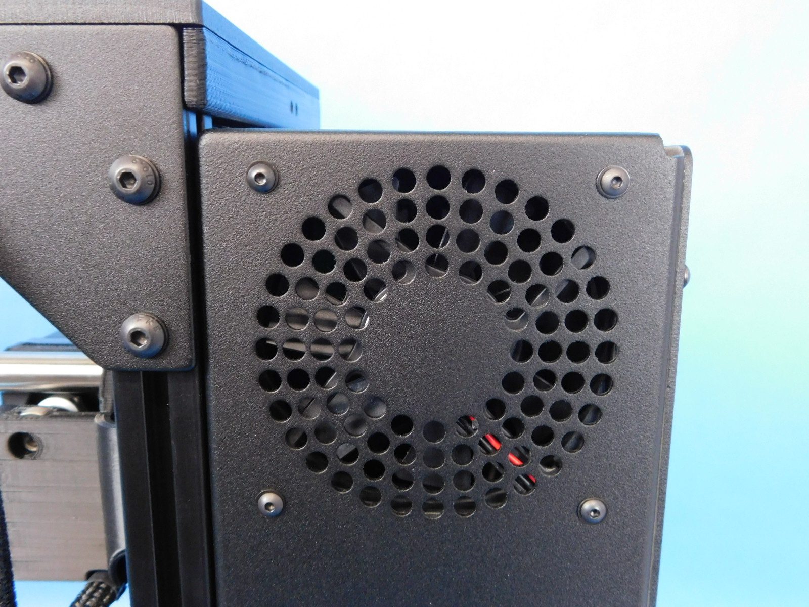
Case fan spins freely and is blowing outwards
Heat sink fan spins freely whenever unit is powered on
Extrusion cooling fan turns on & off as expected (activate through temperature menu)
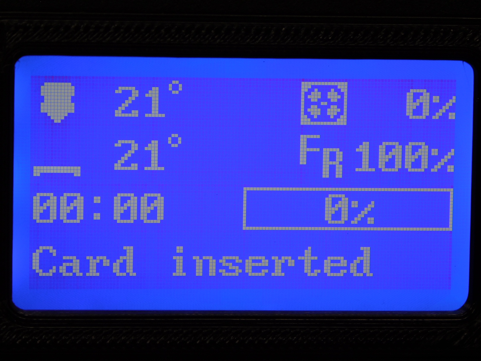
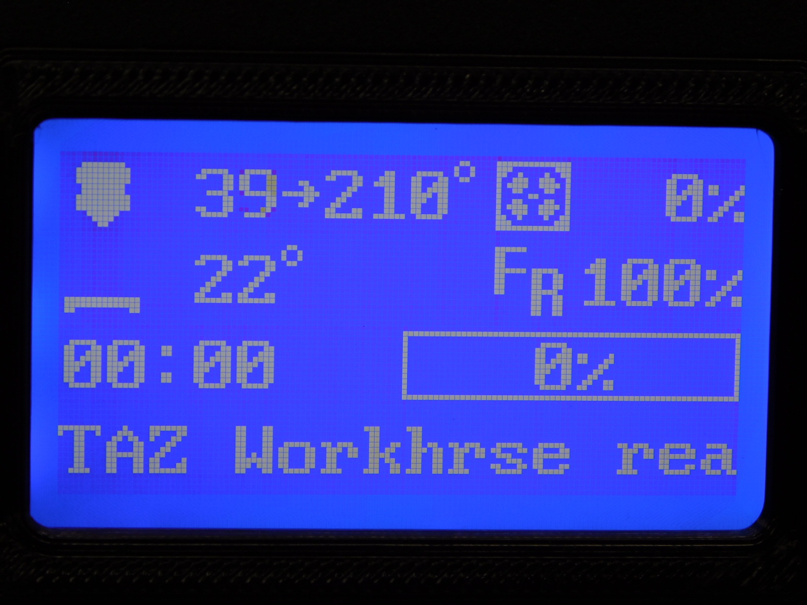
Correct FW version installed: LulzBot TAZ HE 0.5mm v2.0.0.144 Menu > About Printer > FW version
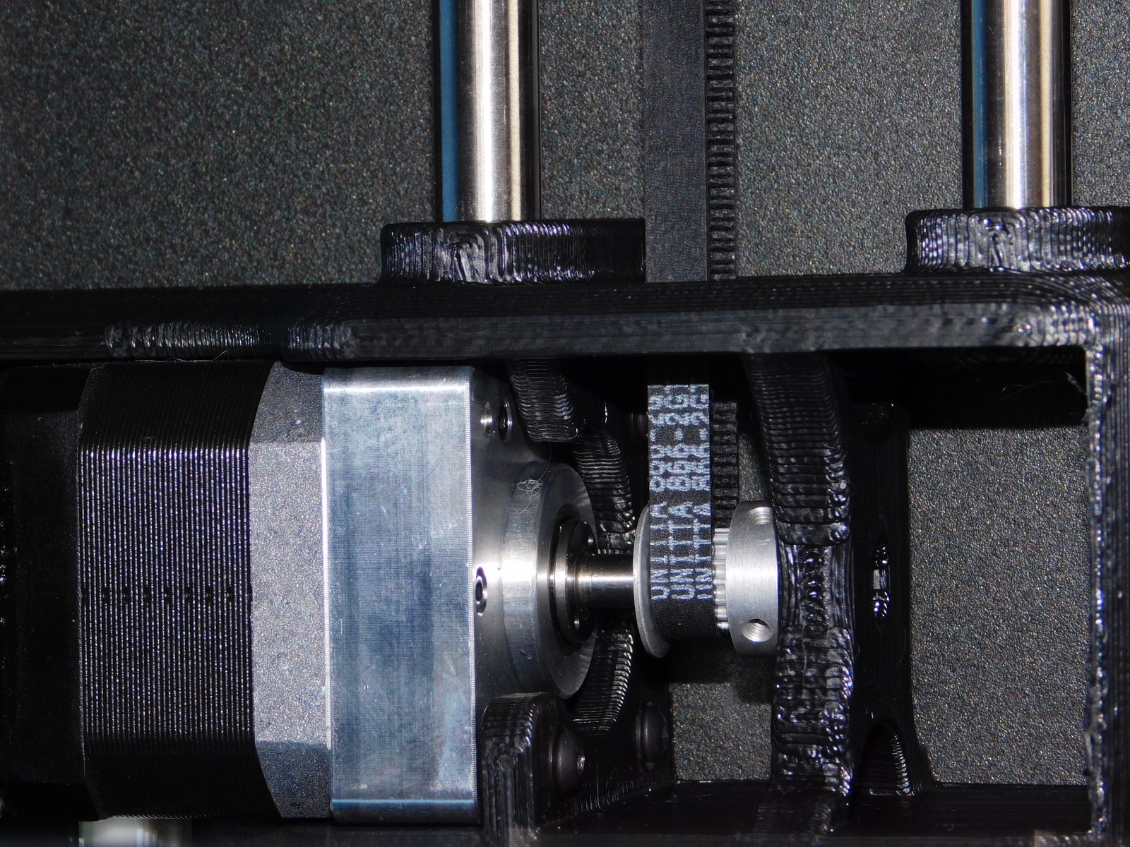
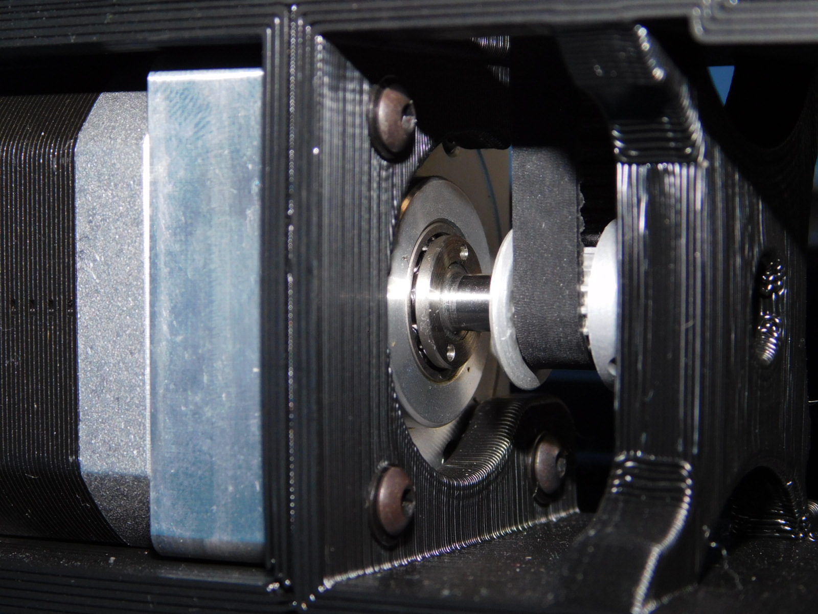
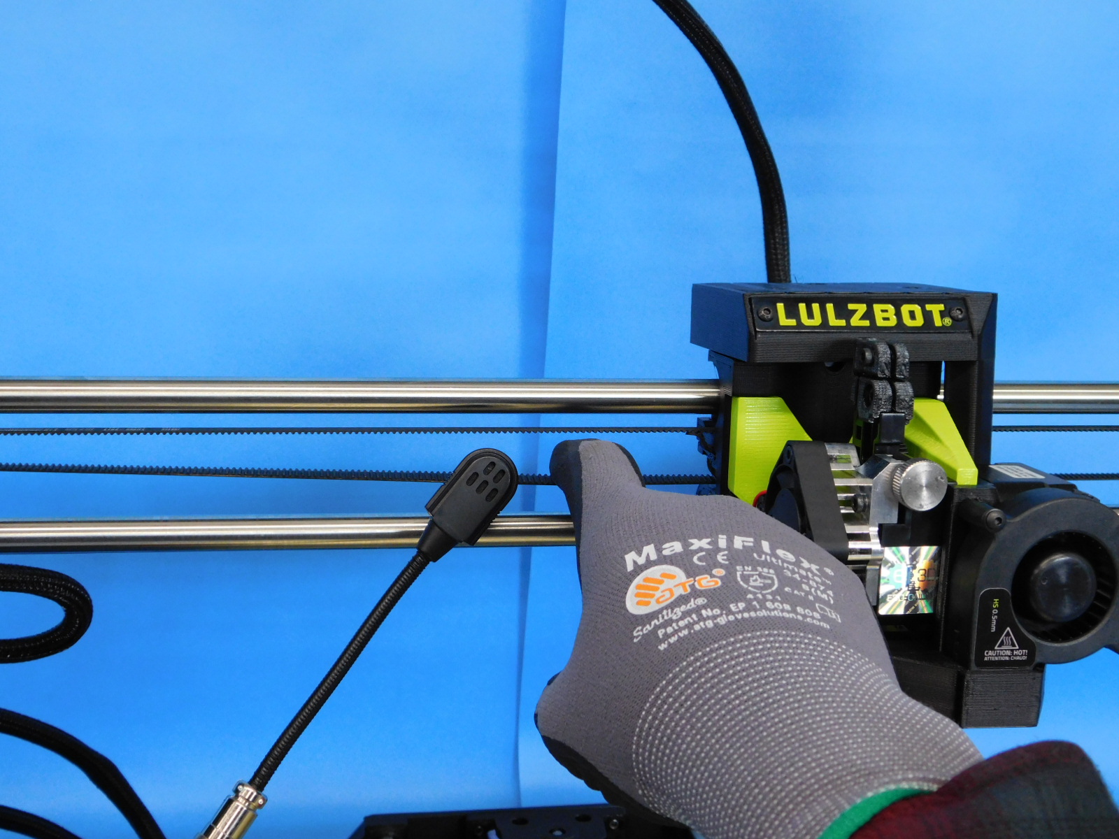
Tools Needed:
Sonic Belt Tensioner
Setting No. 7 for Z belts
Setting No. 8 for X/Y belts
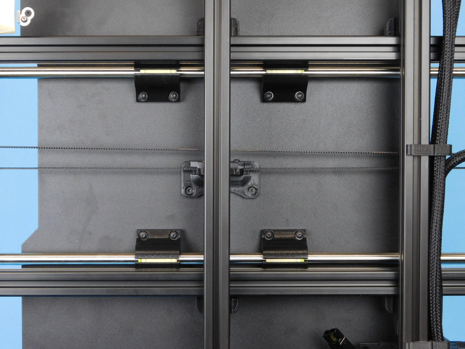
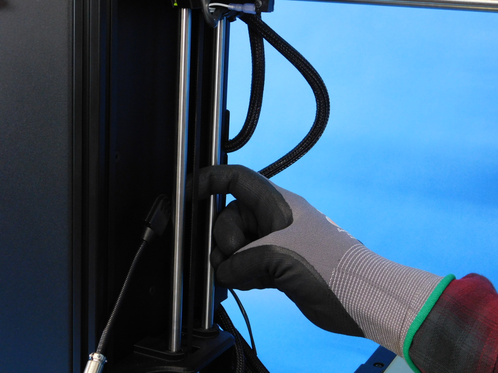
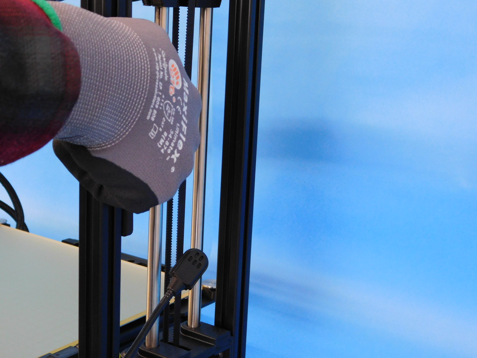
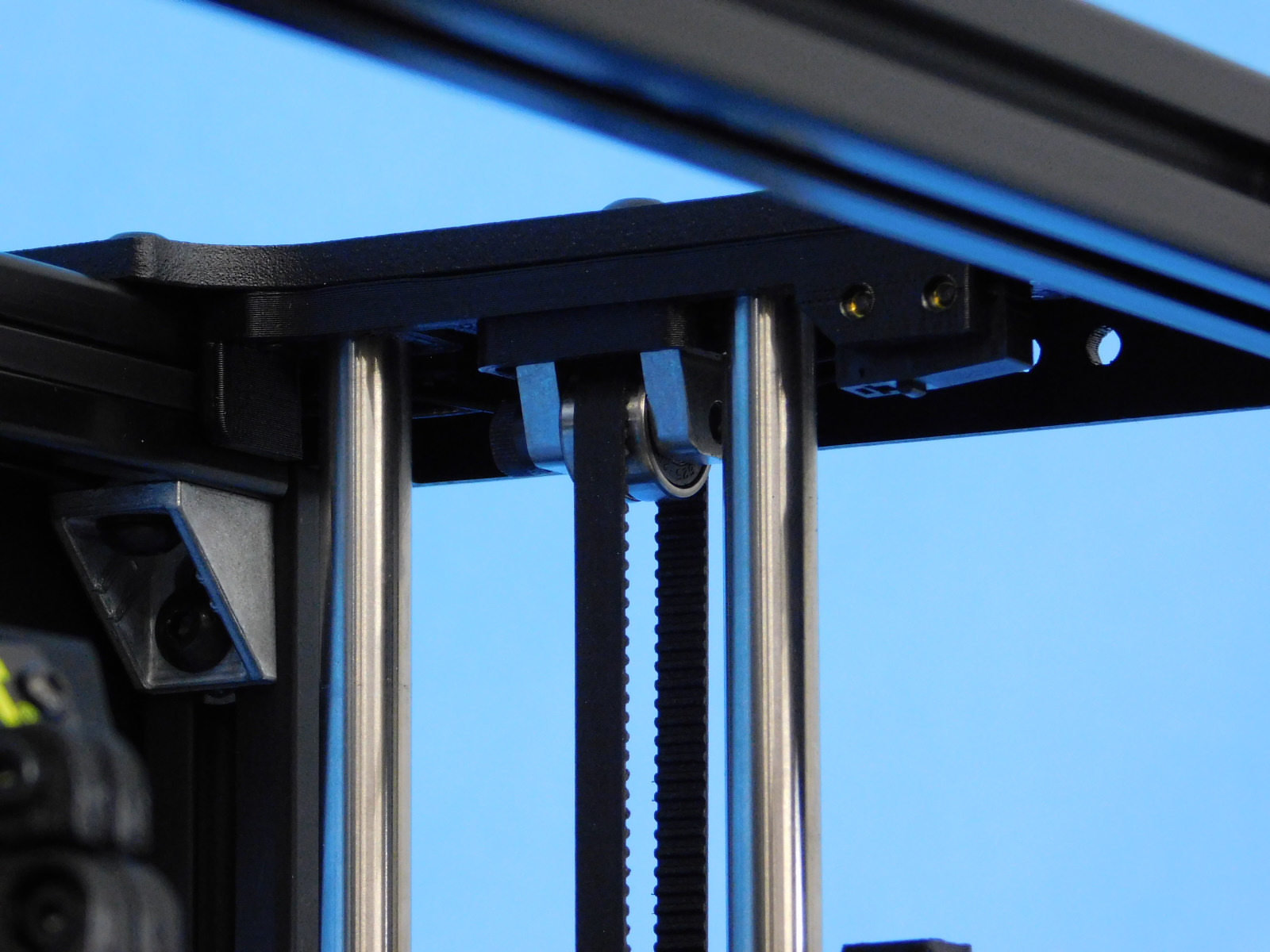
Check the Y-Axis:
With the machine off, start by checking that the Y axis moves smoothly and check for play in bearings
Check the belt tension with a sonic belt tensioner. The belt tension should be between 23-45 Newtons.
Slide the Y axis through its full range of motion and check for binding or play. The bearings should fit snugly on the smooth rods and not wiggle. Try wiggling the bed plate, it should not have any play.
Check the X-Axis:
Check the belt tension with a sonic belt tensioner. The belt tension should be between 23-45 Newtons. Slide the X axis through its full range of motion. Again the X carriage should slide smoothly without binding or have any play in the bearings. The bearings should fit snugly on the smooth rods.
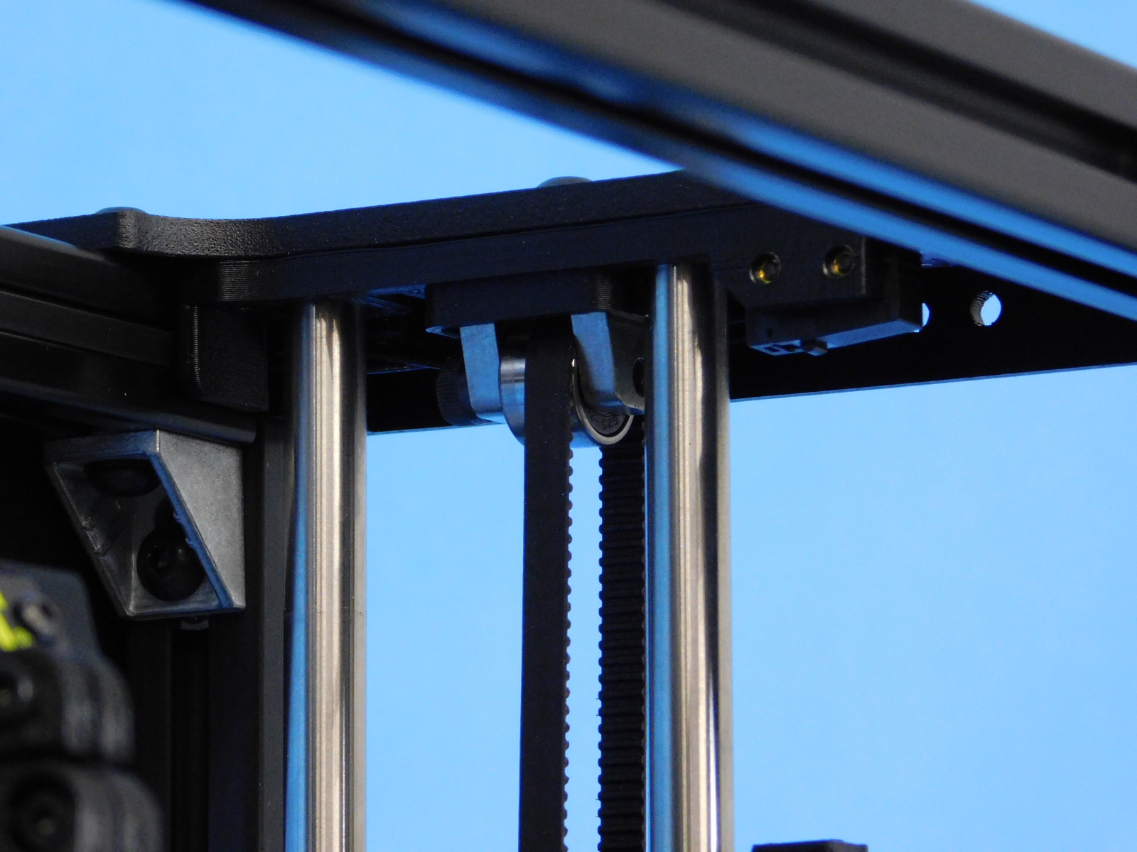
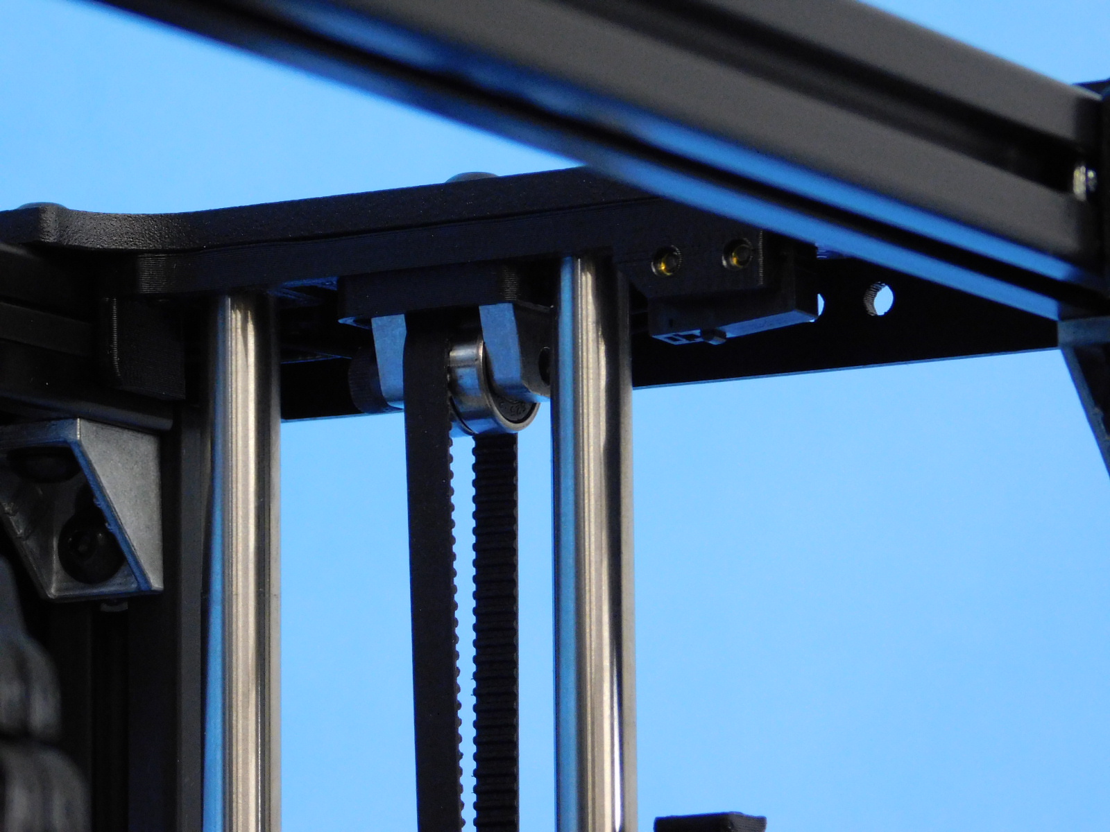
Check the Z-Axis:
Check the belt tension with a sonic belt tensioner. The belt tension should be between 40-90 Newtons. Utilize CuraLE or the LCD controller to move axis through its full range of motion. The Z-Axis should move smoothly through the whole range of motion.
Verify all axes home properly by selecting “Auto Home” from the menu

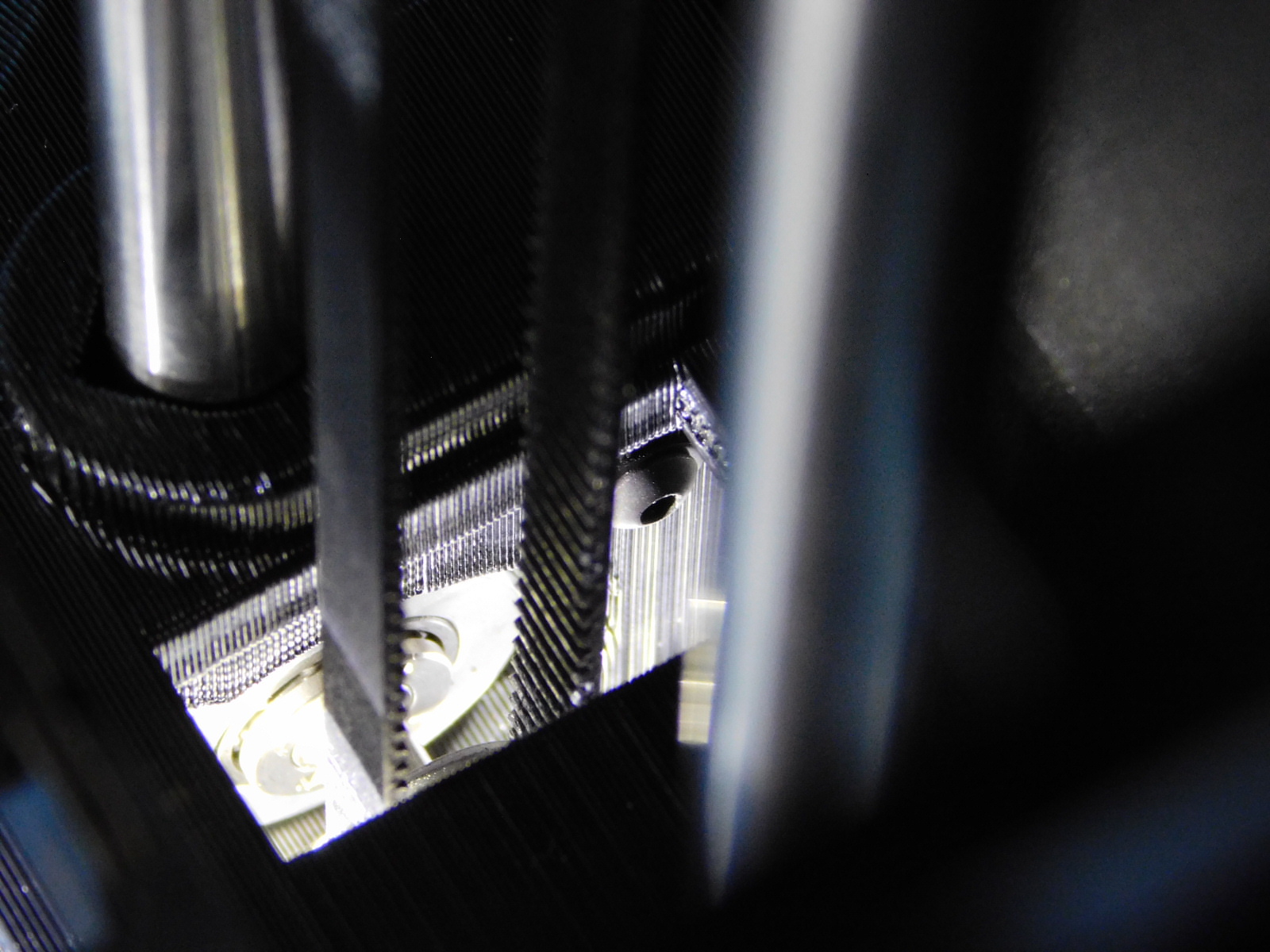
Move each axis through the entire range of motion while observing where the belt rides in each idler.
The belt should not rub on any printed or machined parts.
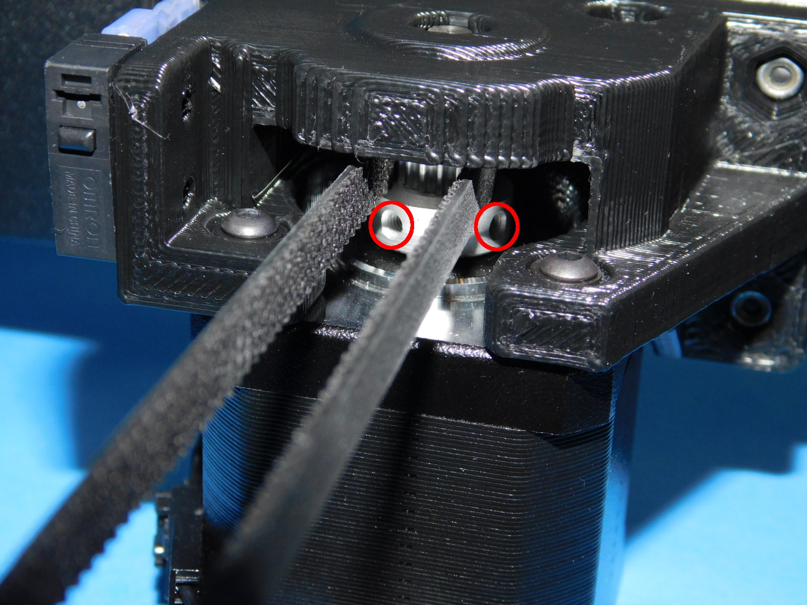
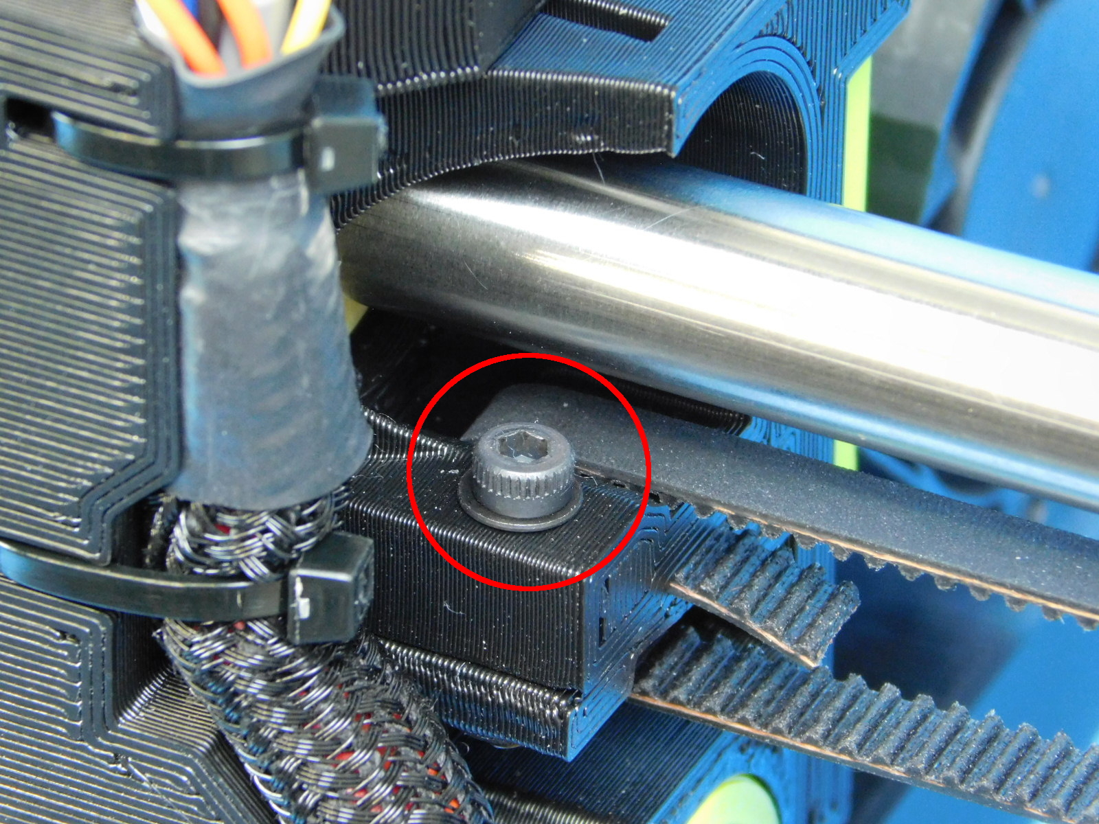
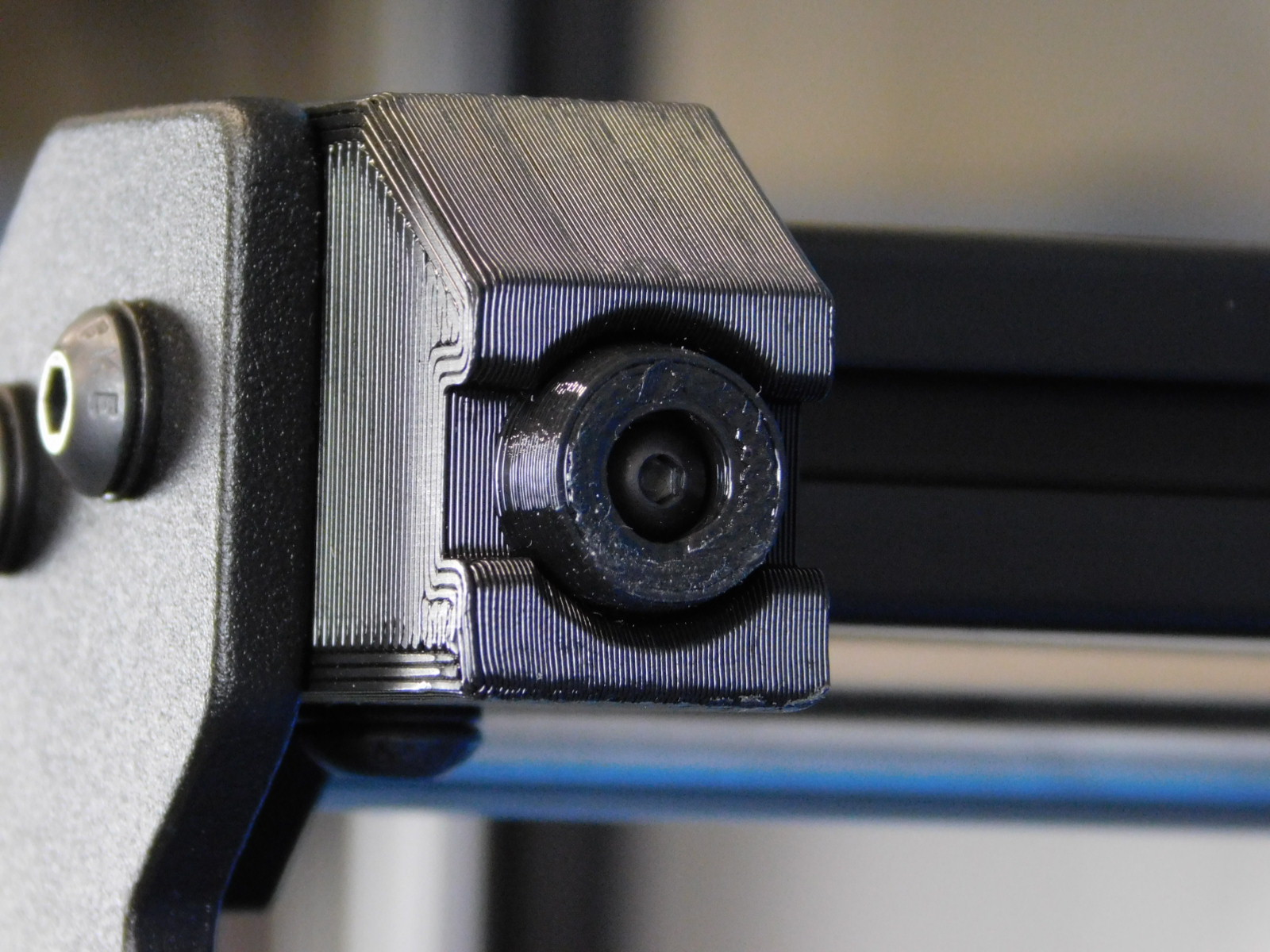
The position of the Z axis belt in the idlers can be adjusted by use of the 2 set screws in the Z-Top plates behind and in front of the Z belt tension screw.
If the belt is riding towards the front, tighten the set screw in front of the Z belt tension screw.
If riding towards the rear, tighten the rear set screw.
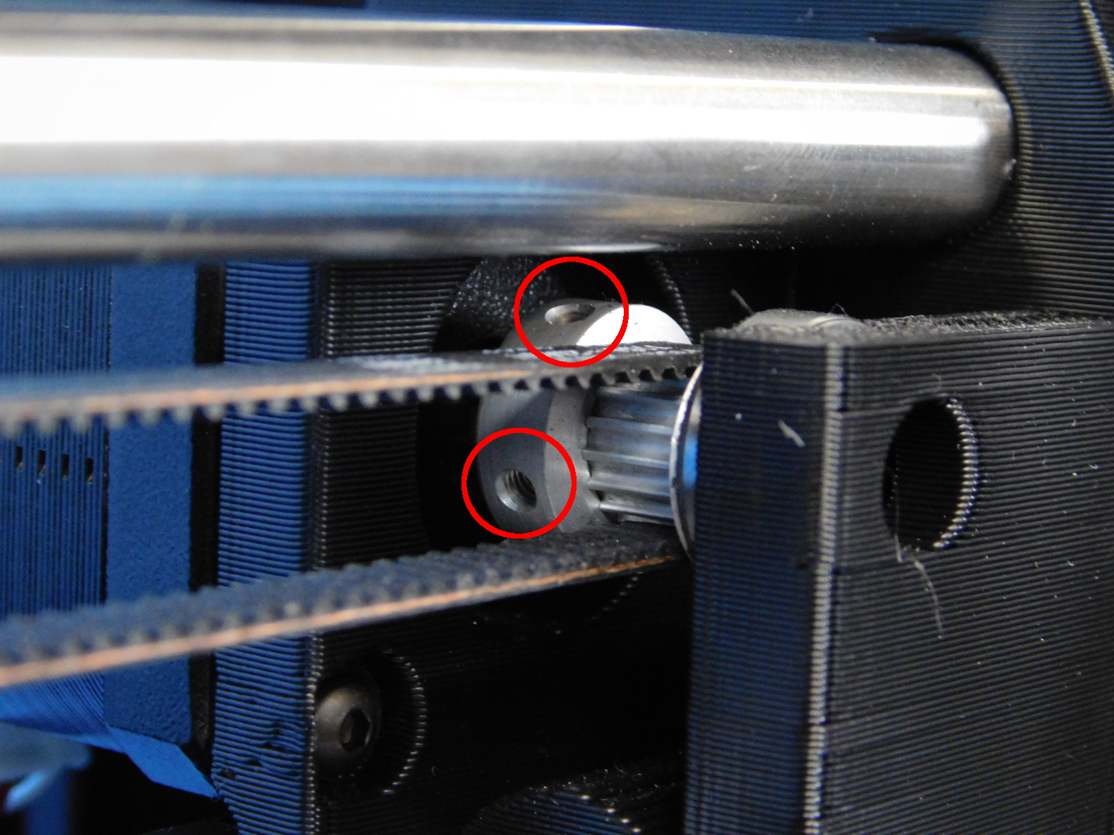
X belt position can be slightly corrected by tightening one of the X belt tensioner screws tighter than the other and thus securing the belt at an angle;
If riding towards the front, tighten the rear tensioner screw further than the front.
If riding towards the rear, tighten the front tensioner screw further than the rear.
Do not load filament into the extruder yet
Place the machine on the burn in rack, connect to power and turn it on.
From the preloaded SD Card, run the burn in gcode
During burn in, listen for any excessive vibration or binding.
Allow the burn in gcode to complete, ensure the quality assurance record is up to date and follows the machine.

This step is best performed prior to loading any filament in the tool head, as even a small amount of residue on any of the nozzle surfaces has the potential to interfere with the calibration
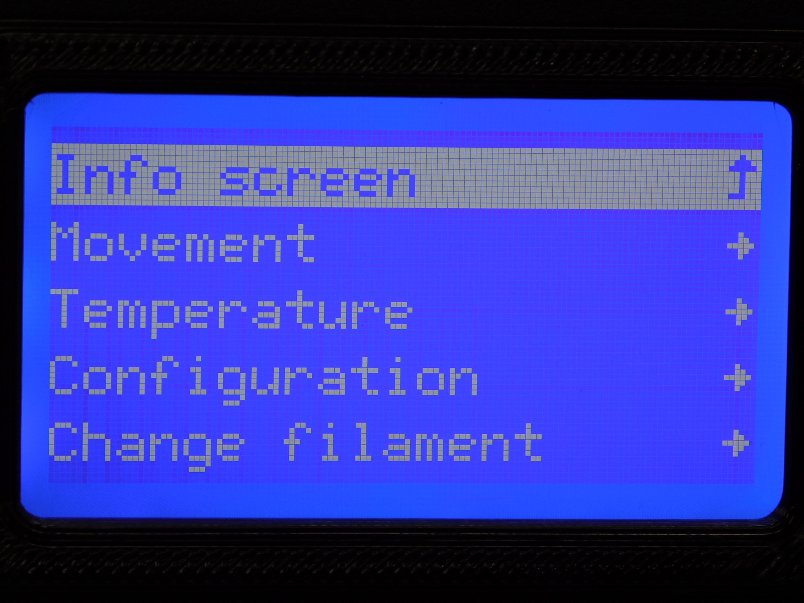
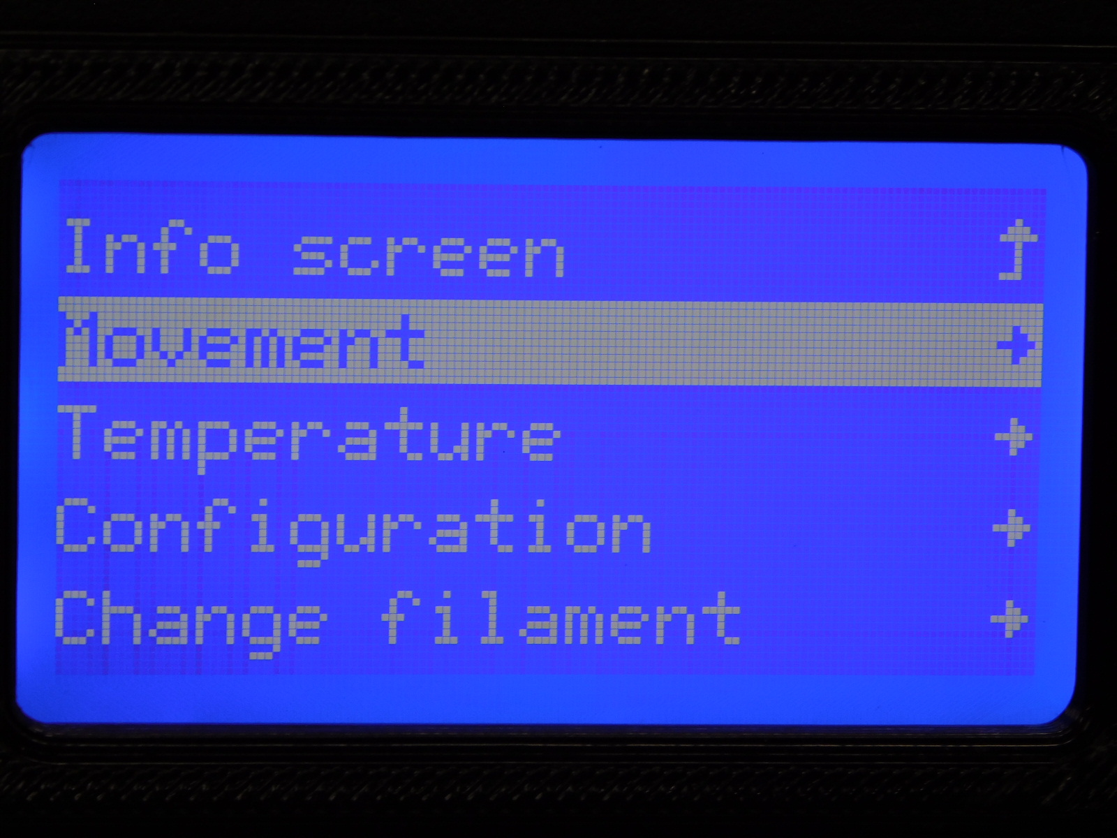
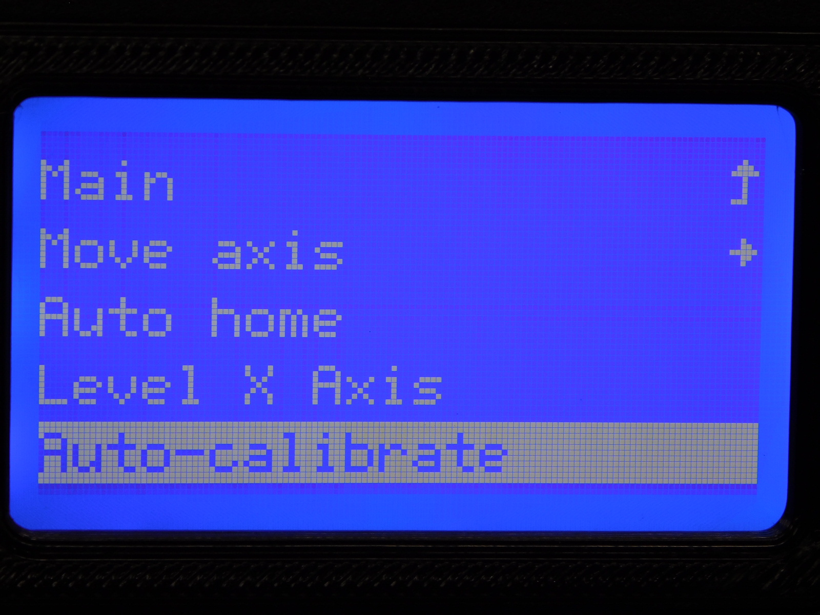
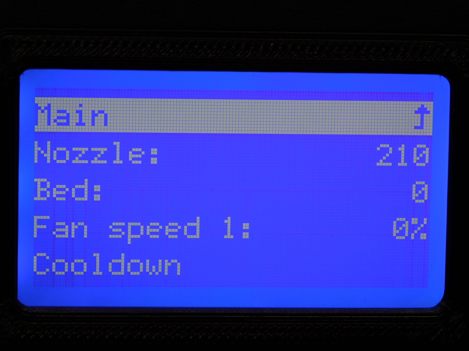
Click the LCD knob to access the menu and navigate to the Movement menu
Select Auto-Calibrate by pressing the knob
The unit will now run through the auto calibration process and takes about 3 minutes to complete.
Watch the beginning to ensure the nozzle finds the calibration cube correctly.
Obtain:
1x- [AS-PR0157] Feed Tube Assembly
PLA sample filament to be used
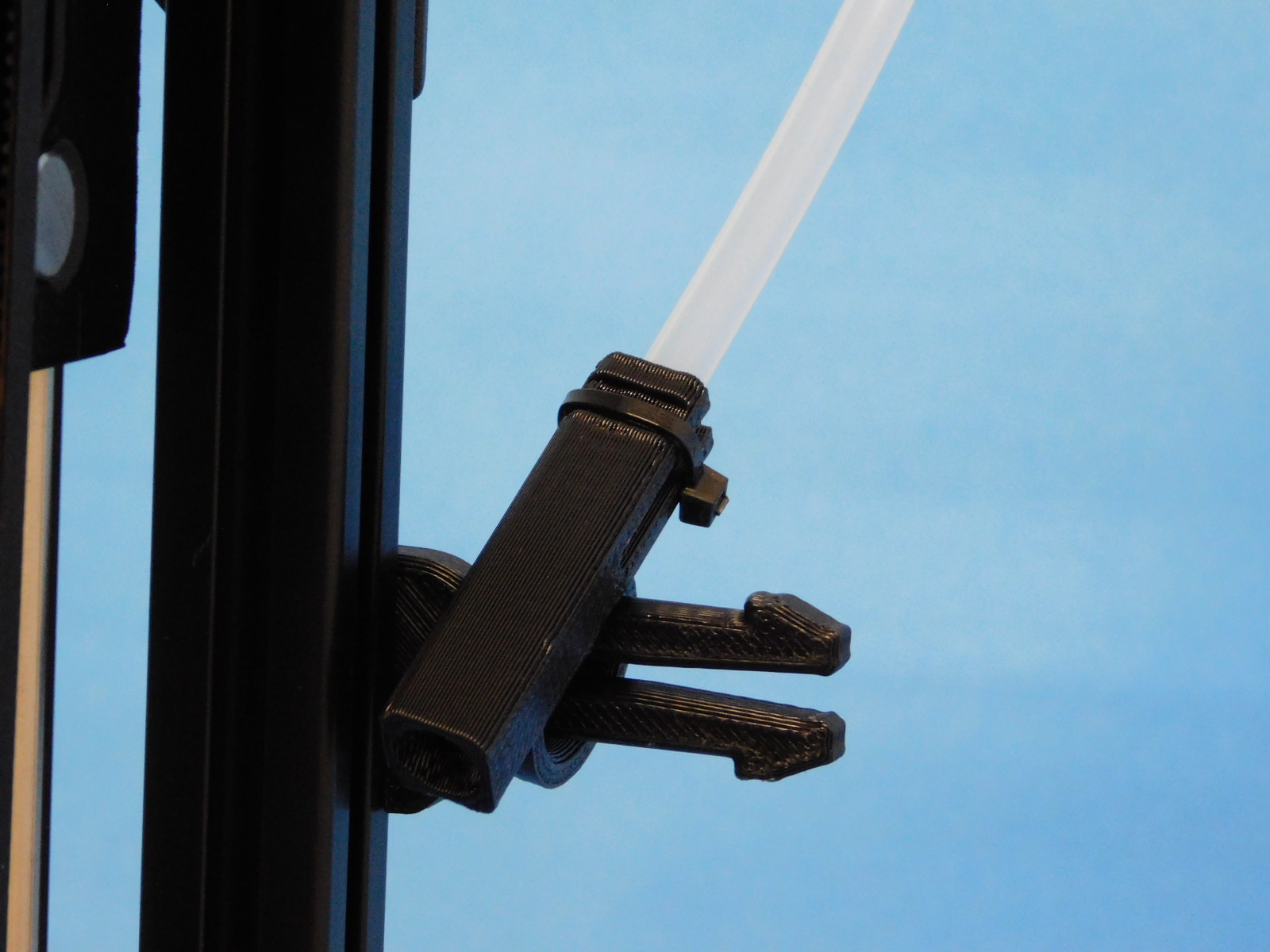
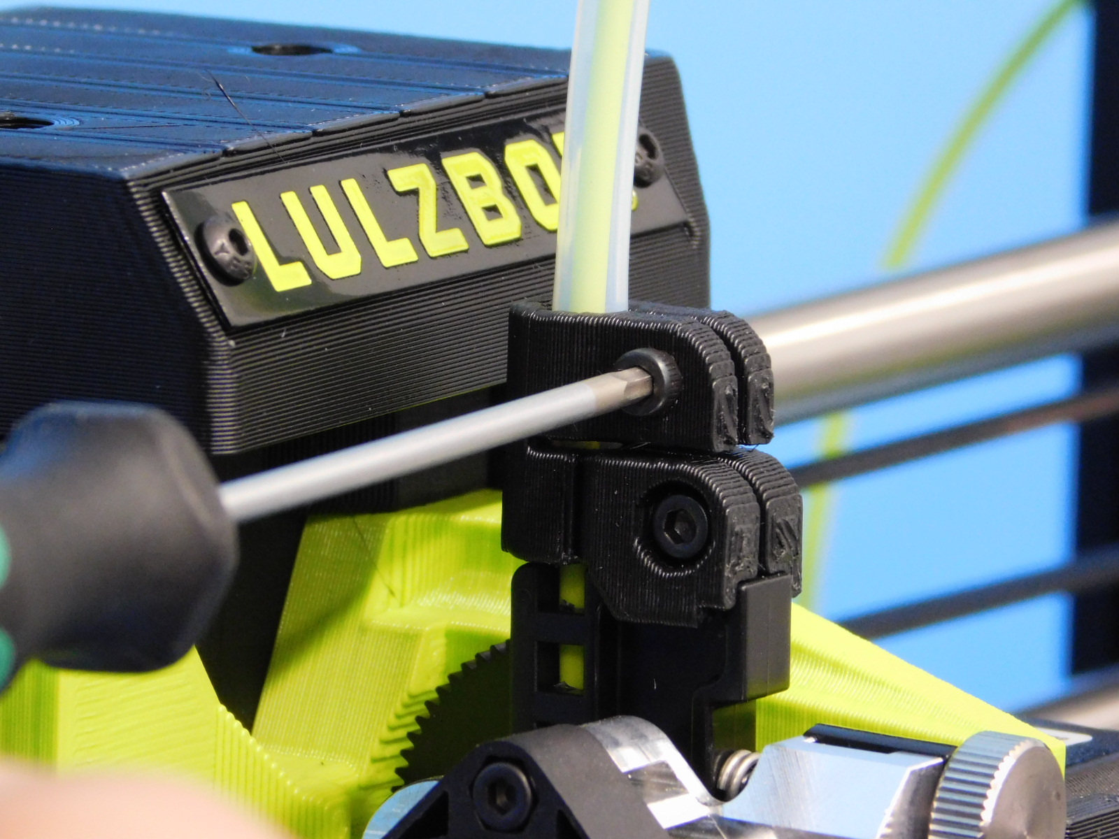
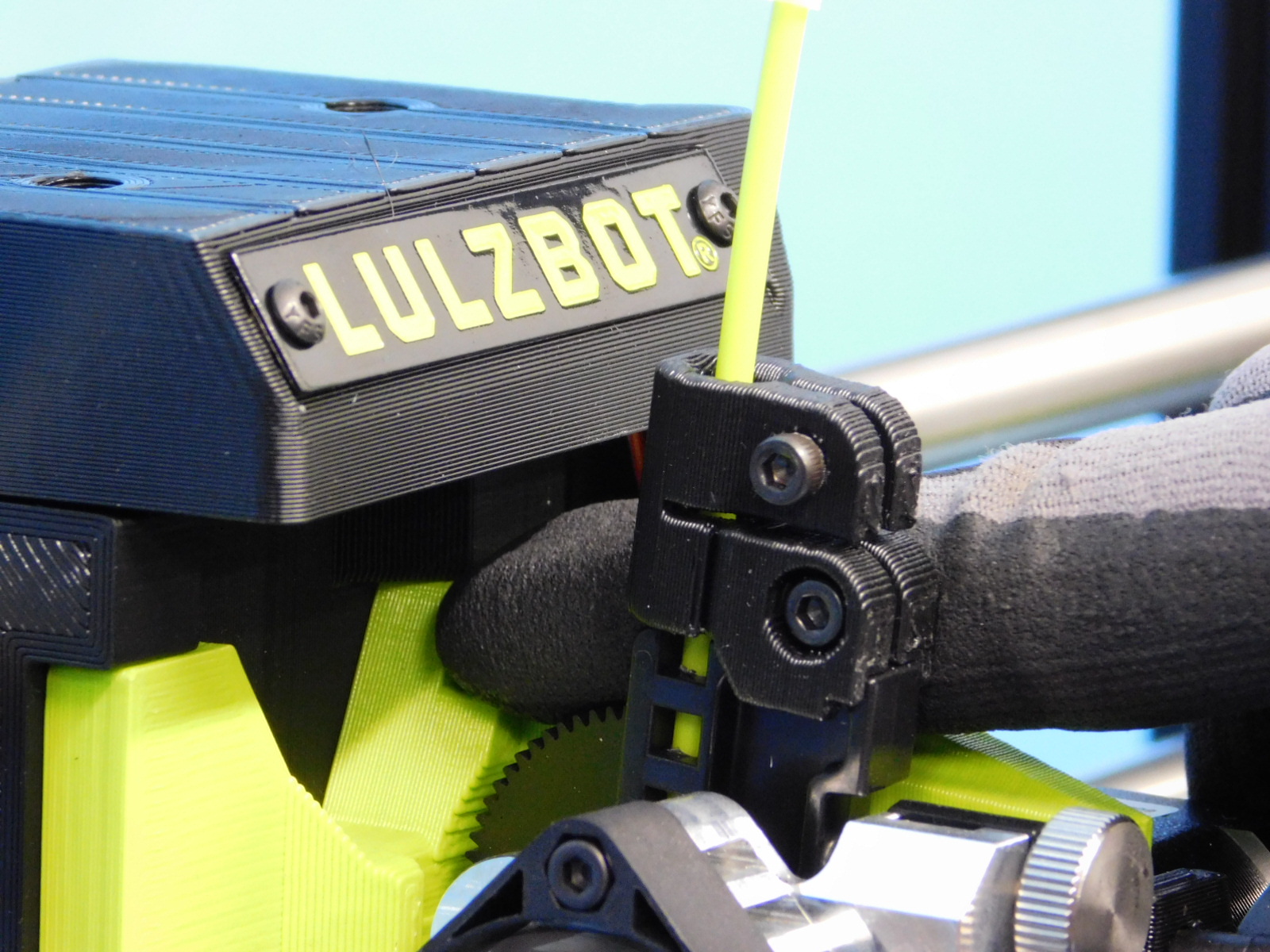
Tilt the feed tube holder so that it is horizontal and slide the ring of the Feed Tube Assembly [AS-PR0157] onto it.
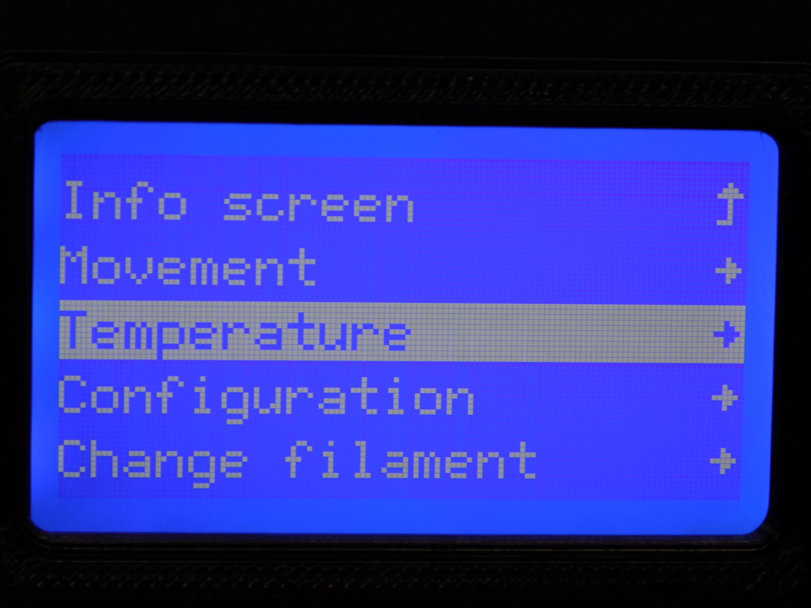
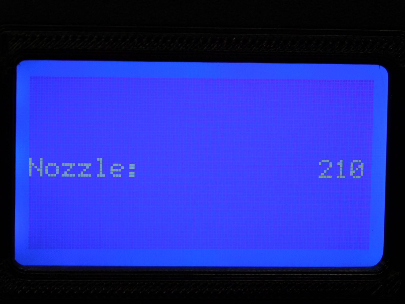
Navigate to the temperature menu in the LCD and begin heating the extruder to 210c.
Feed filament through the feed tube at the right rear of the unit and through the idler lever of the extruder.
Push the end of the Feed Tube Assembly [AS-PR0157] into the Idler Tube Clamp, tighten the upper tube clamp screw.
Use your thumb or index finger to rotate the top of the extruder gear towards you until filament begins to extrude from the nozzle tip.


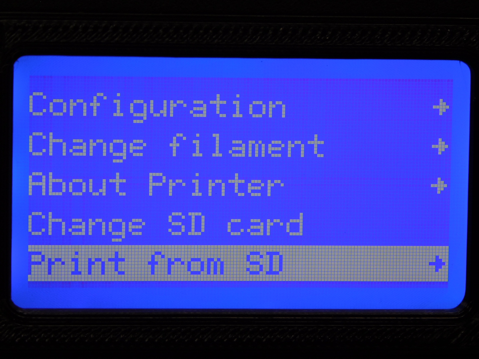
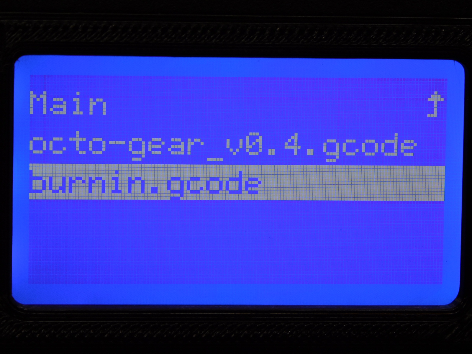
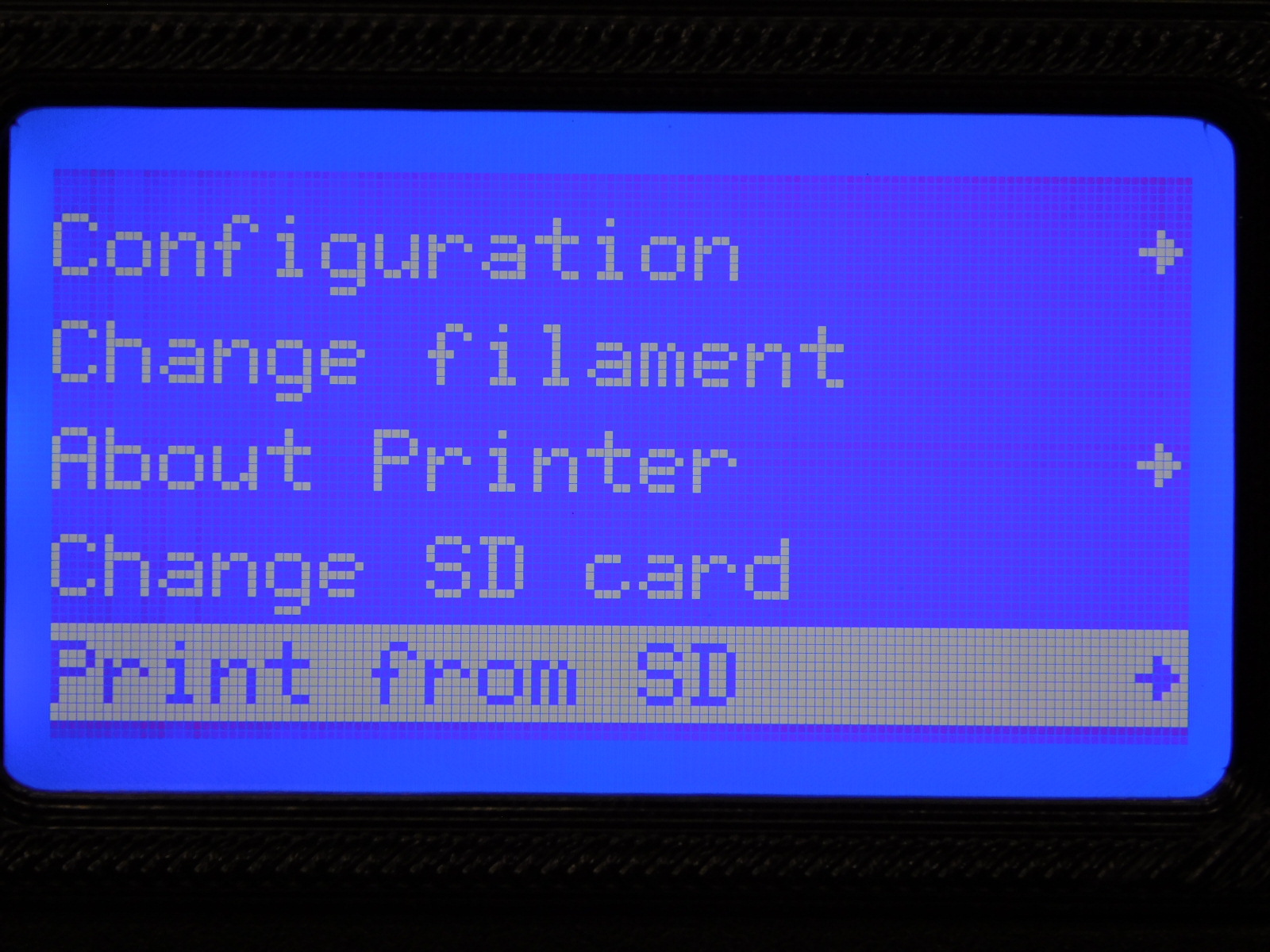
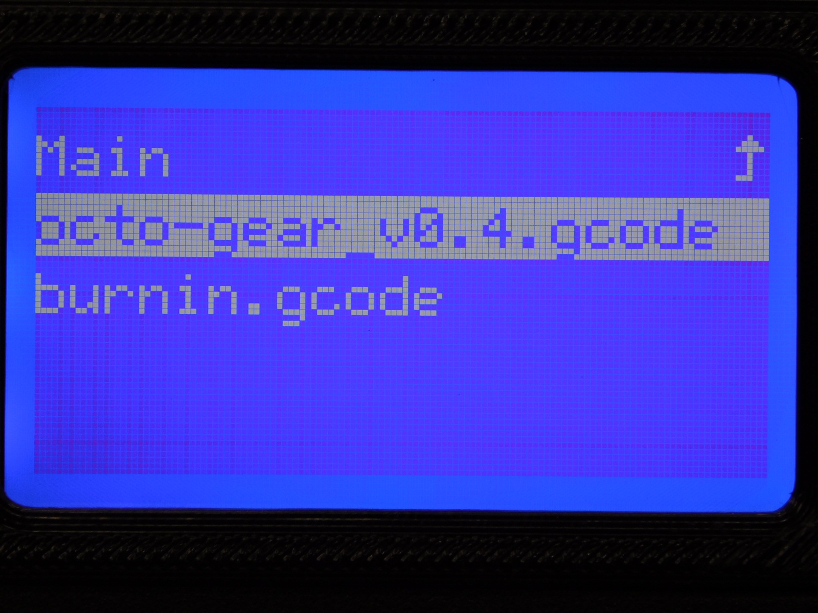
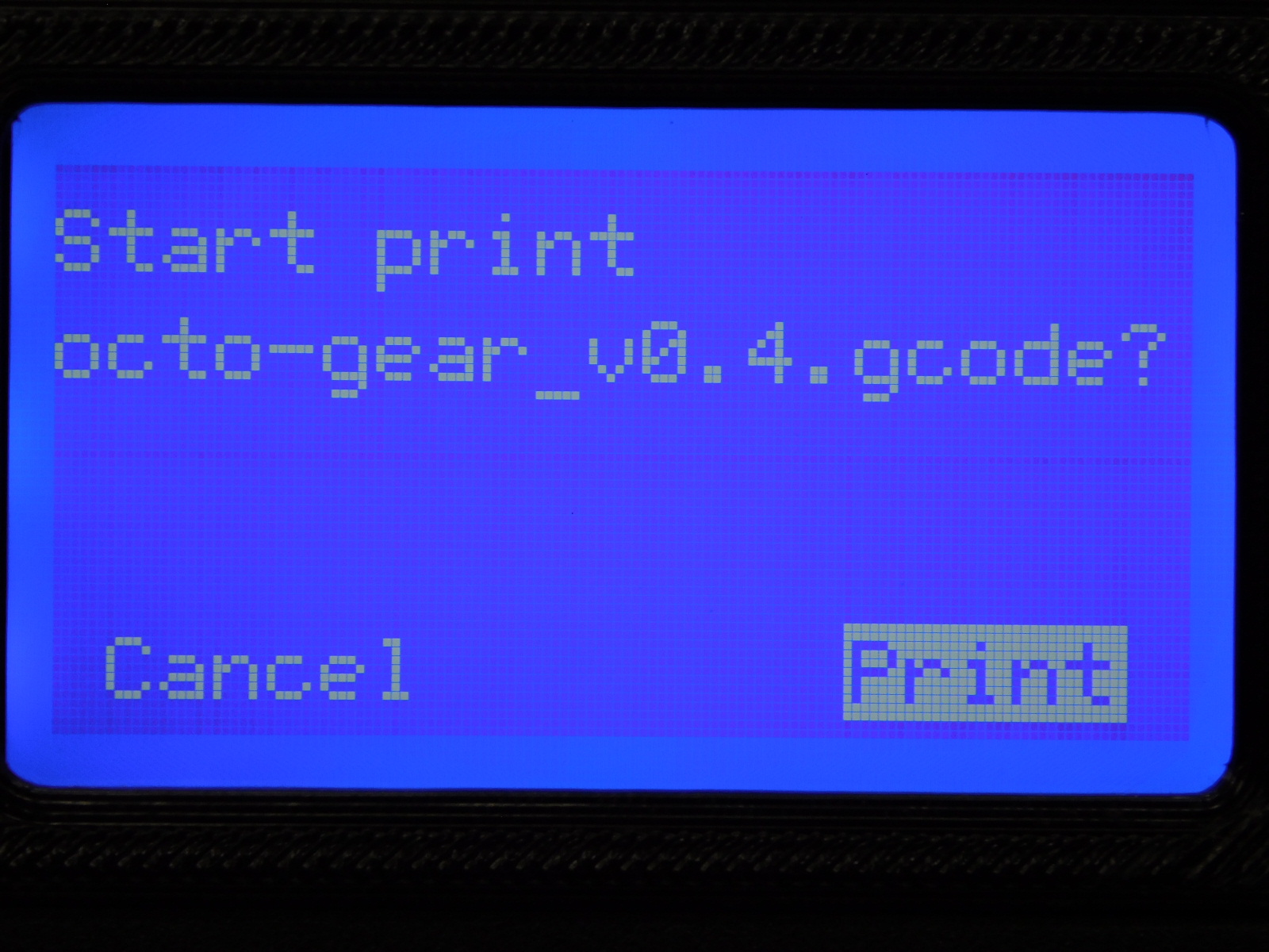
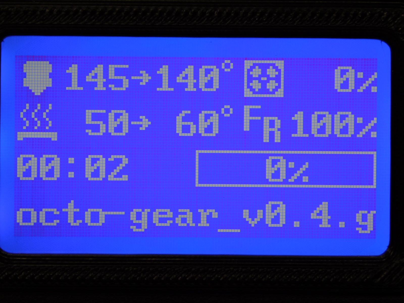
Run the Octo-Gear sample print from the preloaded SD Card
Menu>Print from SD>OctoGear_v0.4.gcode>Print
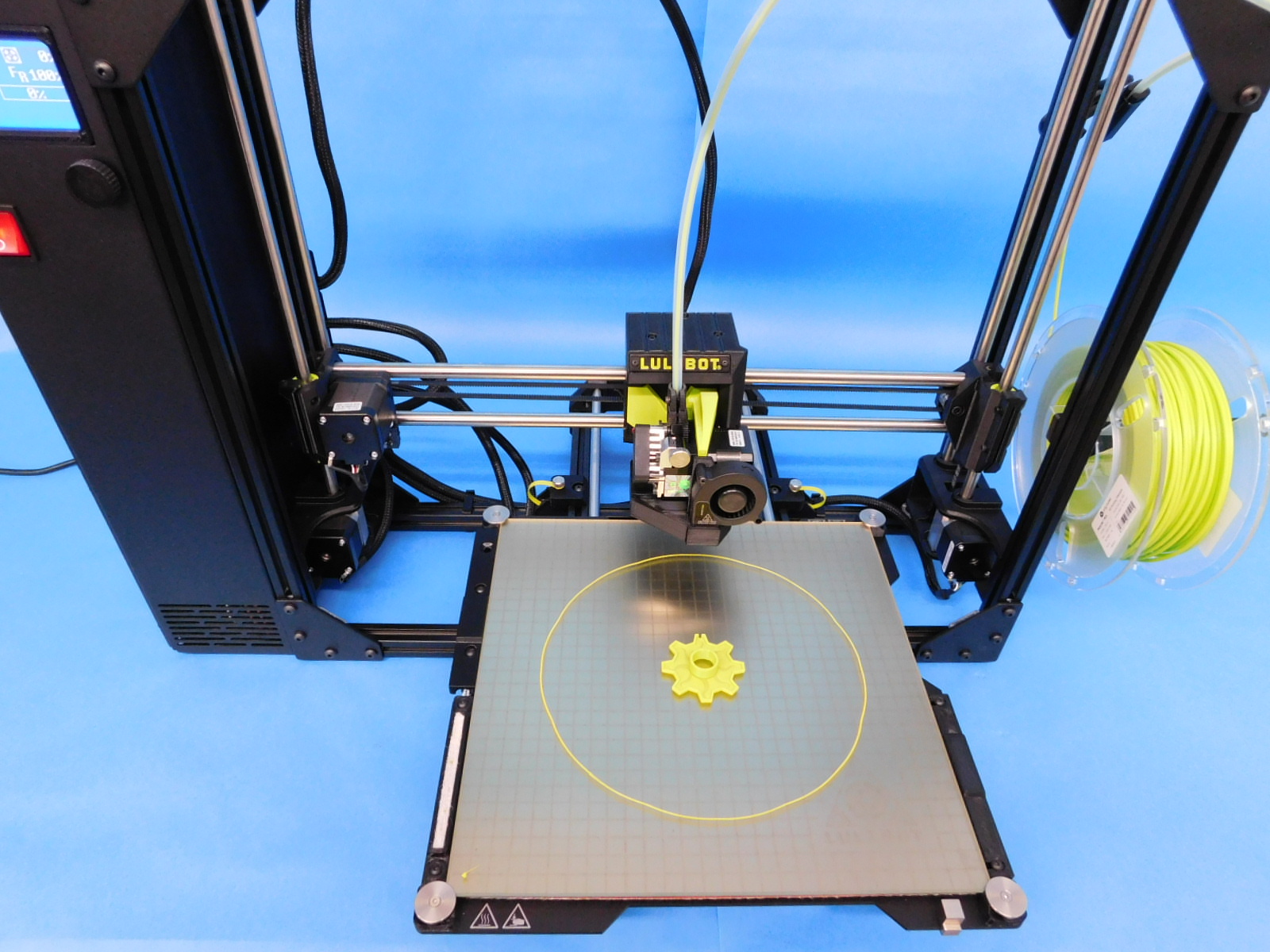
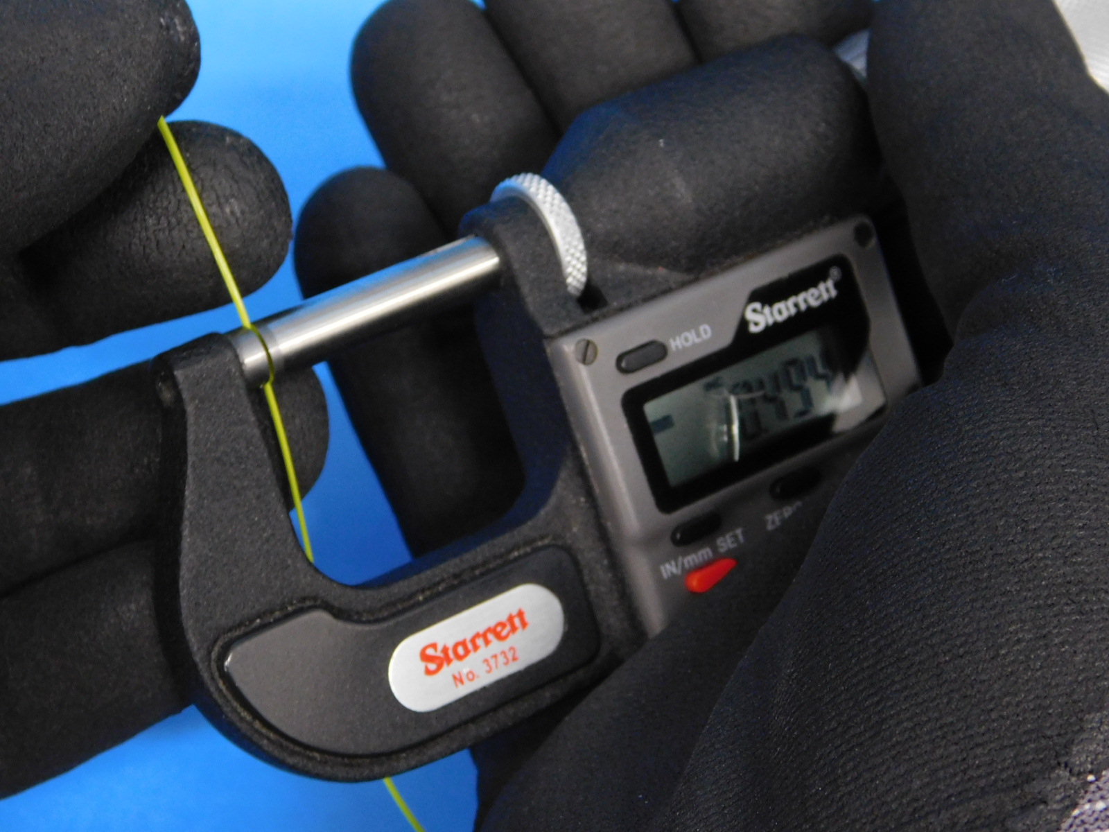
Measure the skirt from the calibration print with a digital micrometer
Acceptable range: 0.3-0.45mm
Ideal: 0.4mm
Measure at least 2 points, one on the left, one on the right.
If either measurement is outside of the acceptable range, adjust the Z-offset by navigating to
Menu > Configuration > Probe Z offset
Apply the difference between the target and the measured value to the Z offset. For example:
Z offset: -1.2mm
Skirt measures 0.41mm left 0.46 right
Adjust until larger measurement falls within acceptable range, to lower the nozzle into the build plate, make the Z offset more negative. If attempting to raise nozzle position, make Z offset more positive.
New Z offset: -1.25mm
Run the calibration print again to verify the offset adjustment.
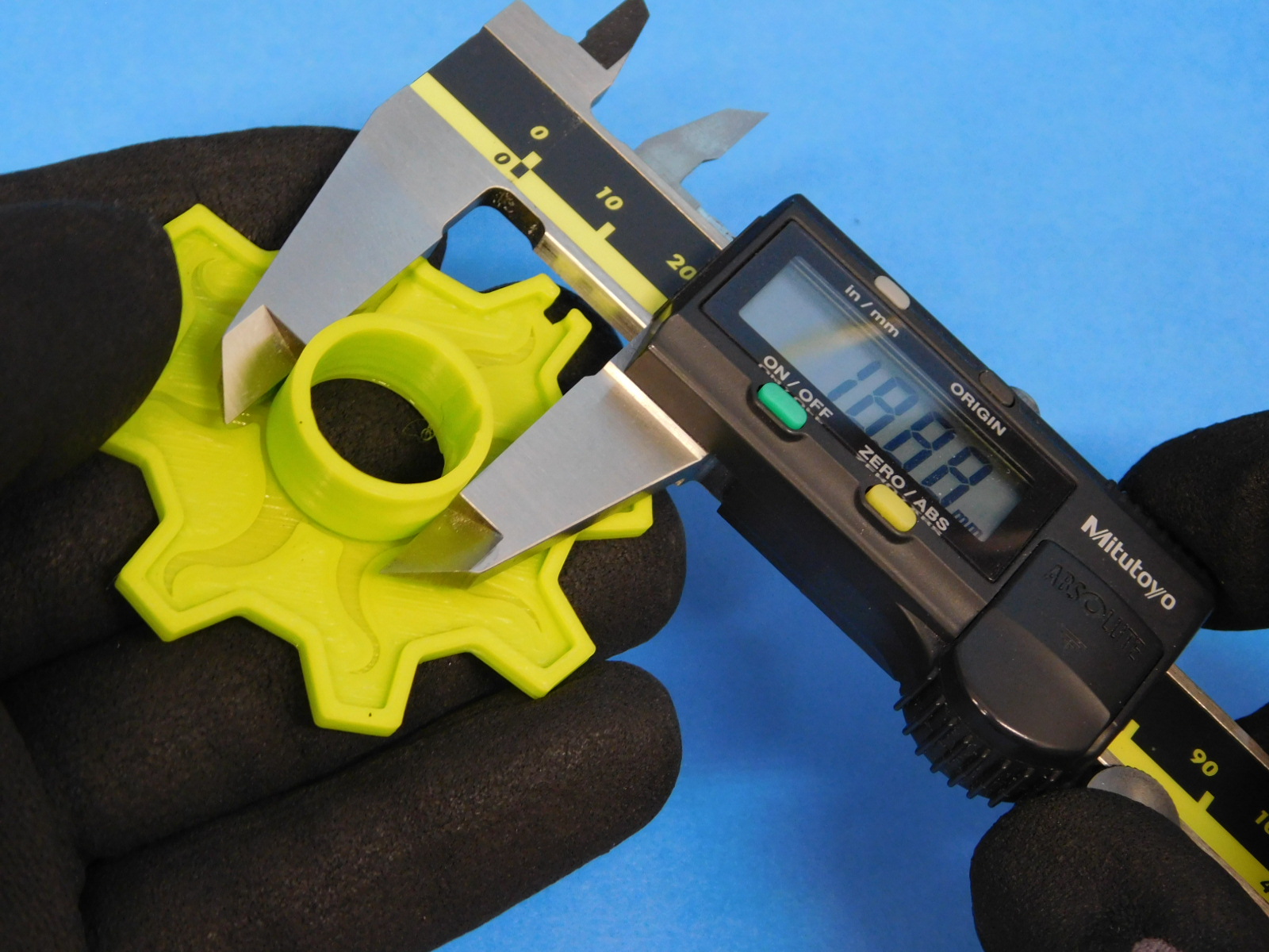
Remove the Octo-Gear sample print from the print bed, be careful not to scratch the print surface.
Using a pair of digital calipers, measure the outside of the center circle tower (19mm).
Spin the print in hand while applying gentle closing pressure on the calipers.
Measurements within the range of 18.75mm to 19.25mm are acceptable.
Measurements outside of that range indicate an issue with the X or Y axis of the machine.
Check for:
Loose belts
Loose motor pulleys
Dragging belts
Axis with excessive overall drag
By this point, you should be able to complete the Quality Assurance record.
Production serial numbers are also tracked in a spreadsheet log, see your supervisor for questions regarding logging.
Please complete the Quality Assurance record, log the machine’s serial number, and pass the unit, the cables tested with it, the test print, the USB drive, and the QA record to packaging.
Nicely done!