Open HardwareAssembly Instructions
Guides for installation and assembly of the LulzBot line of products made by FAME 3D LLC.
Guides for installation and assembly of the LulzBot line of products made by FAME 3D LLC.
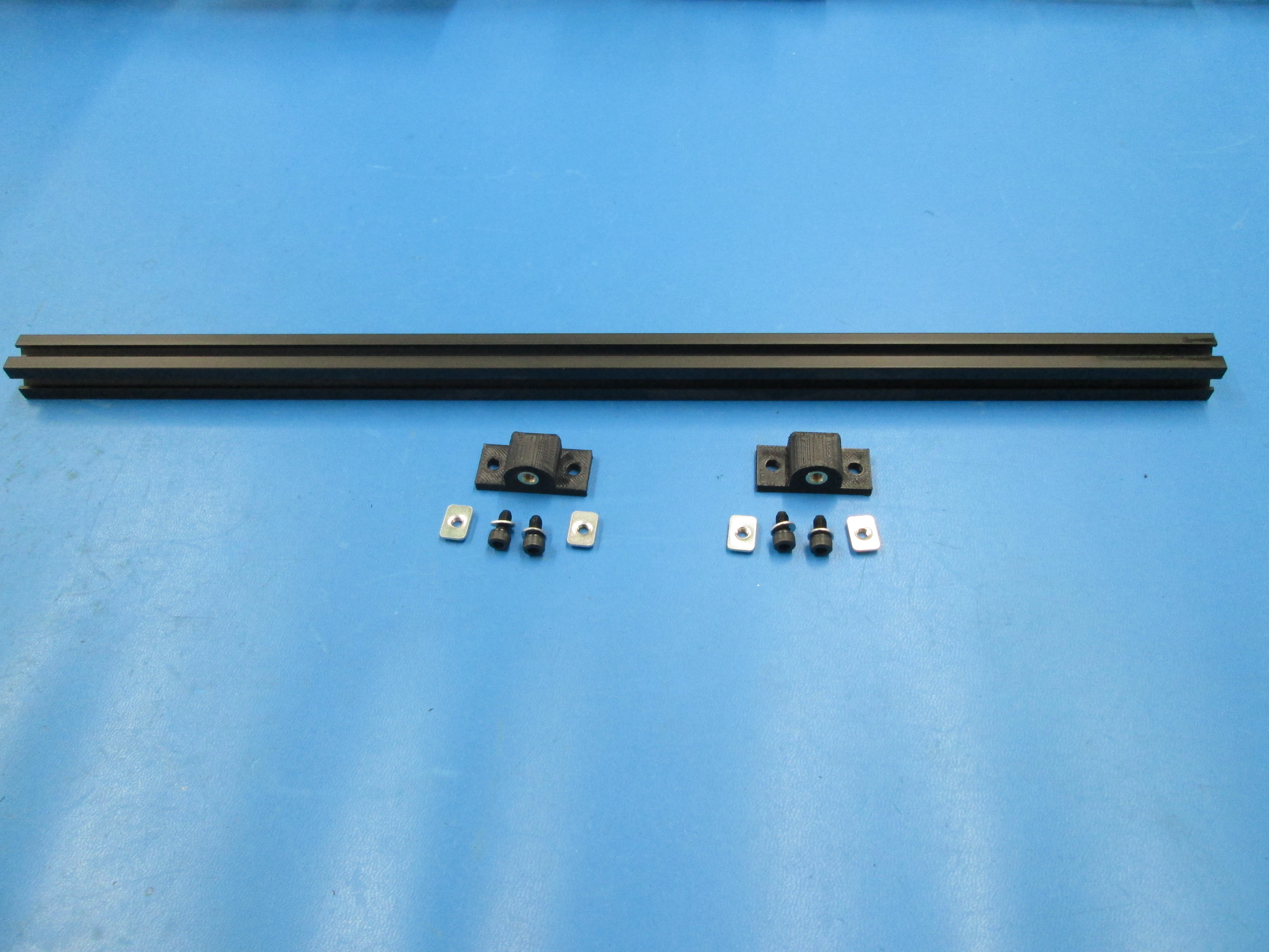
Components:
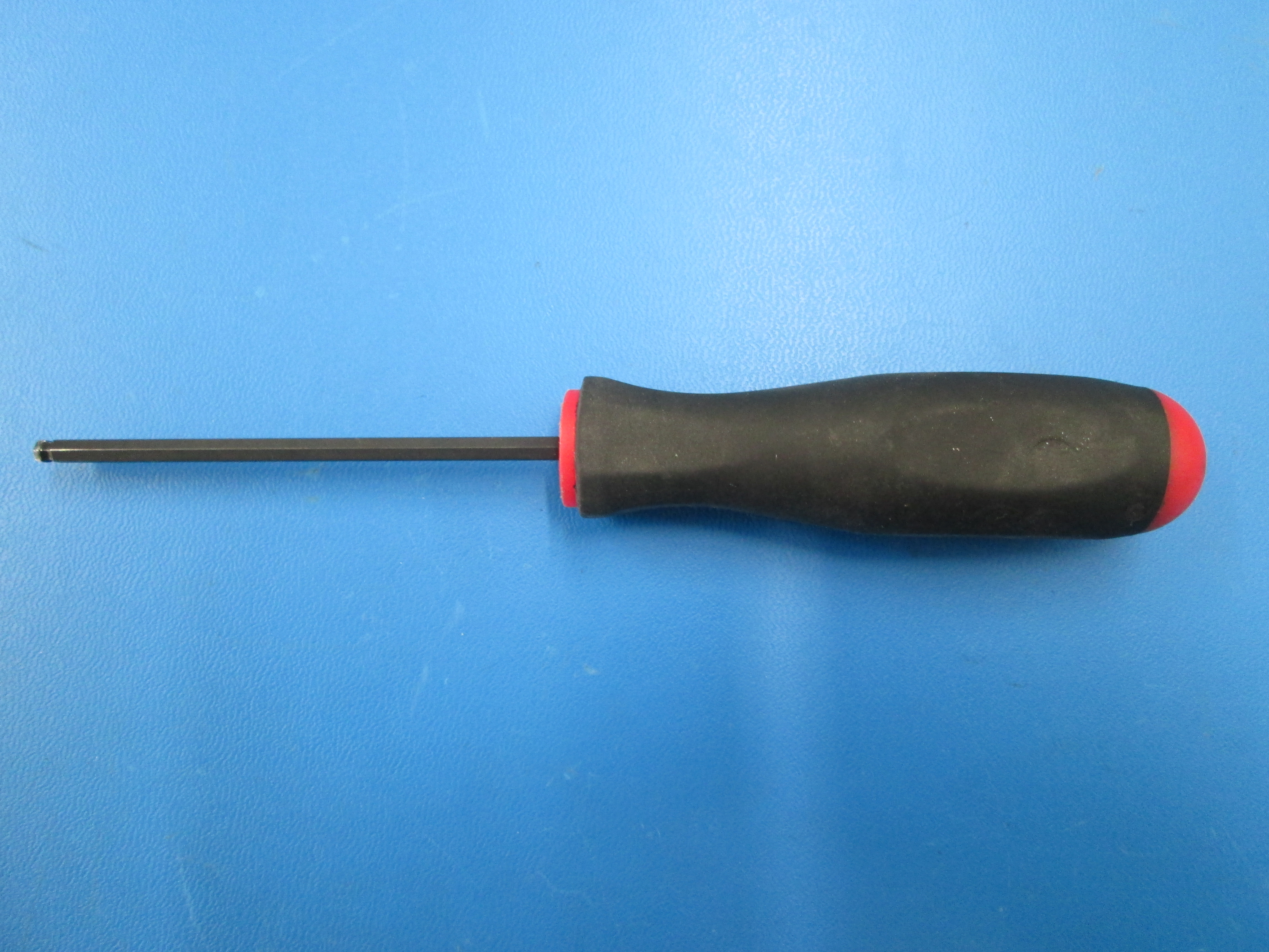
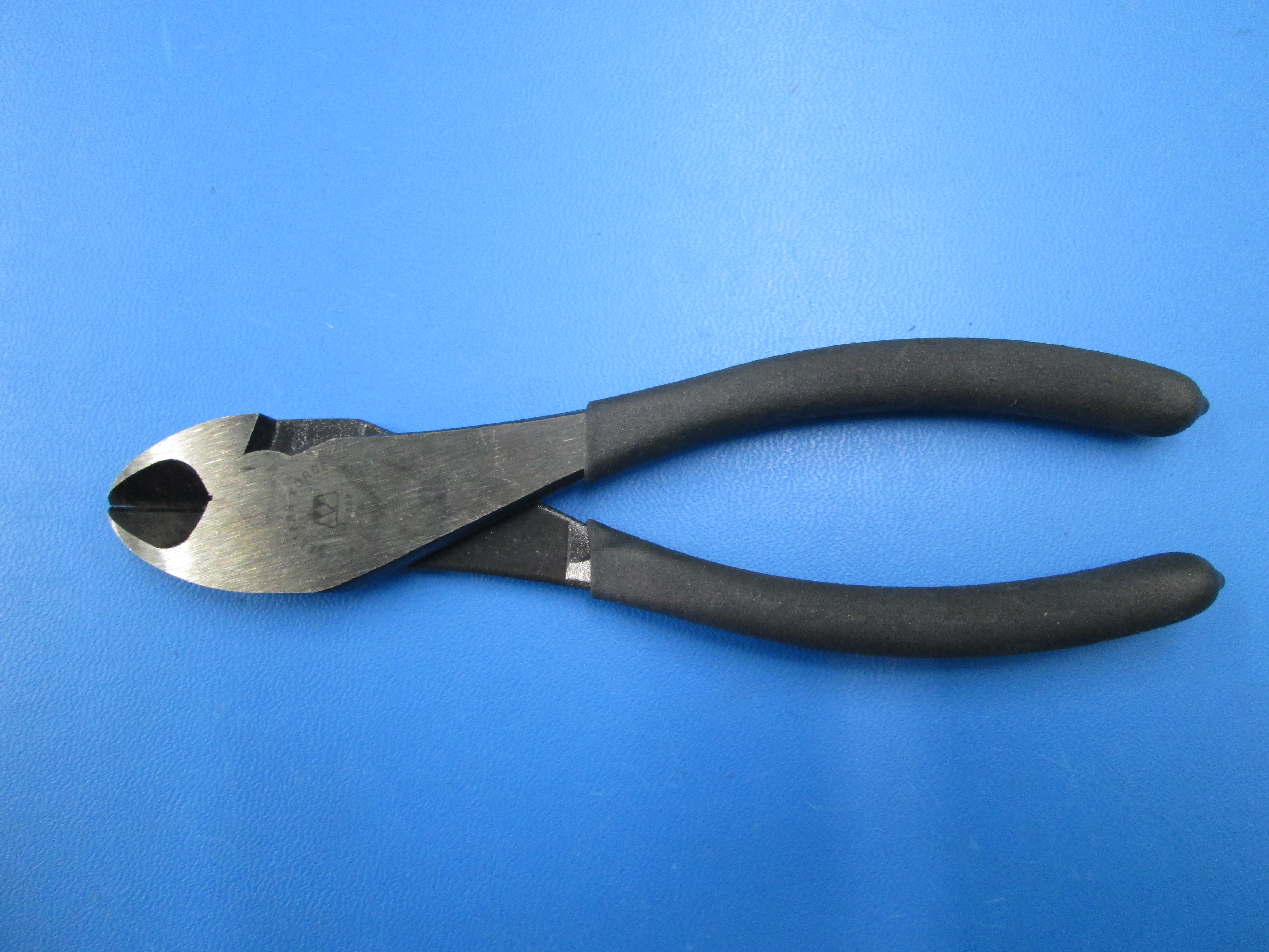
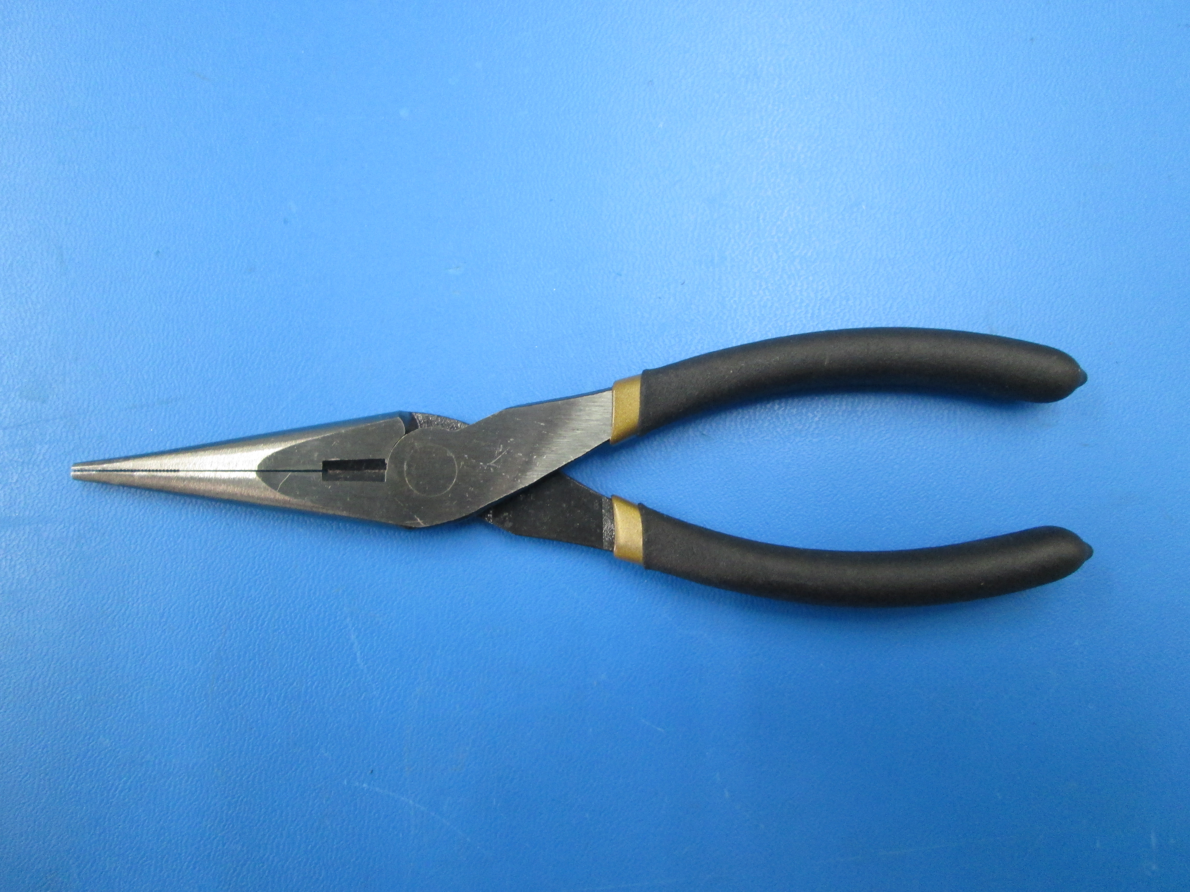
Tools:

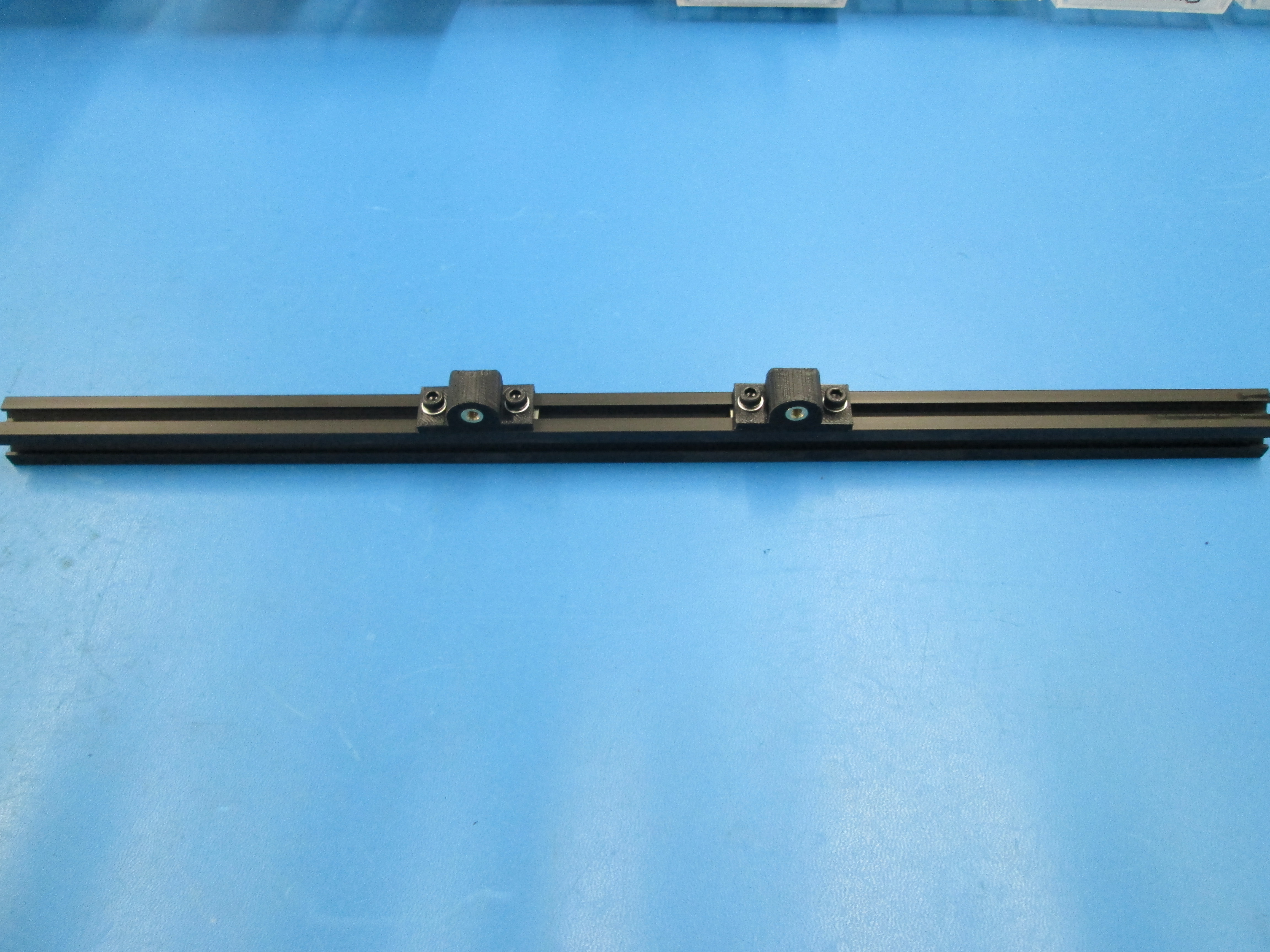
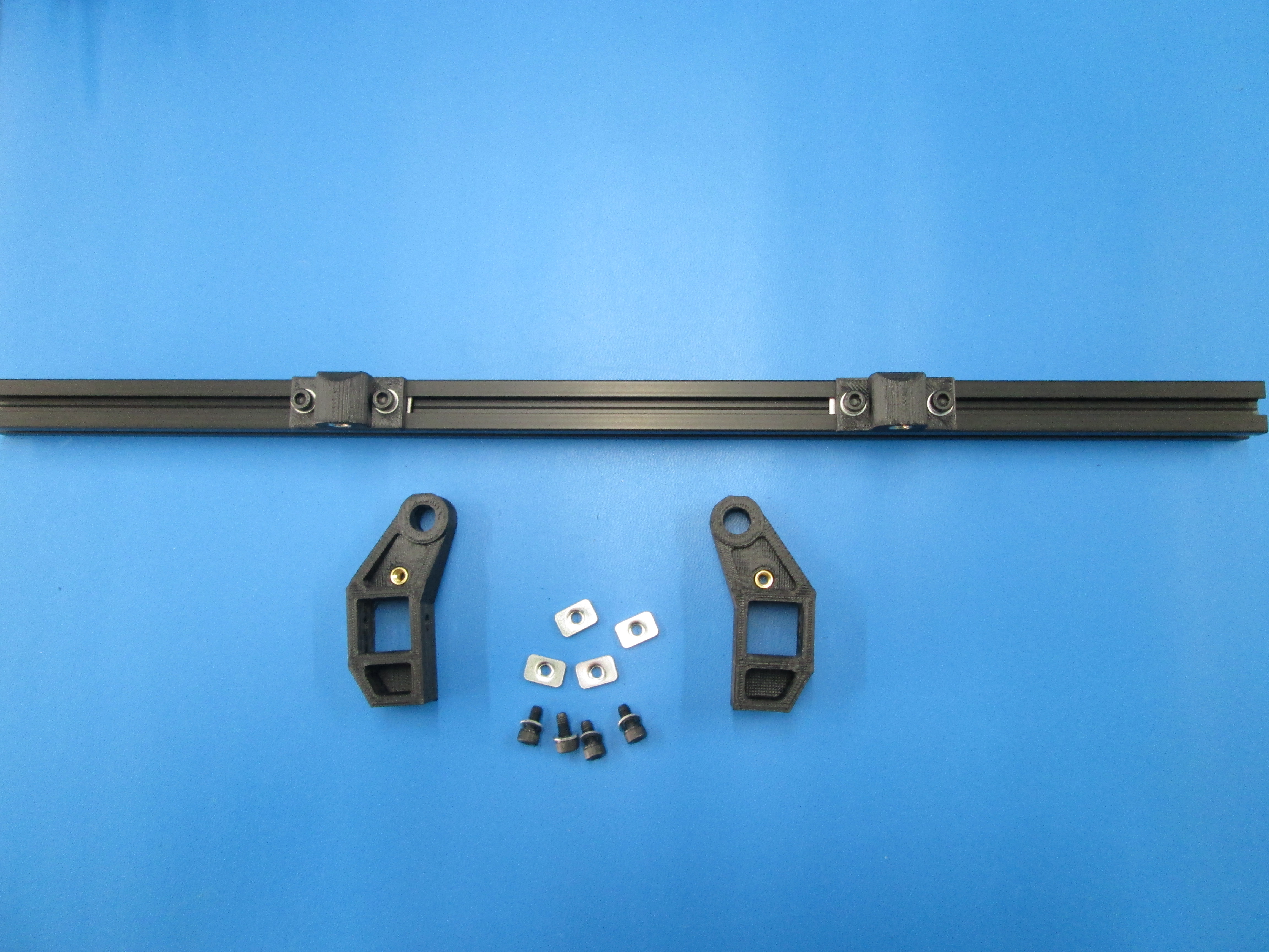
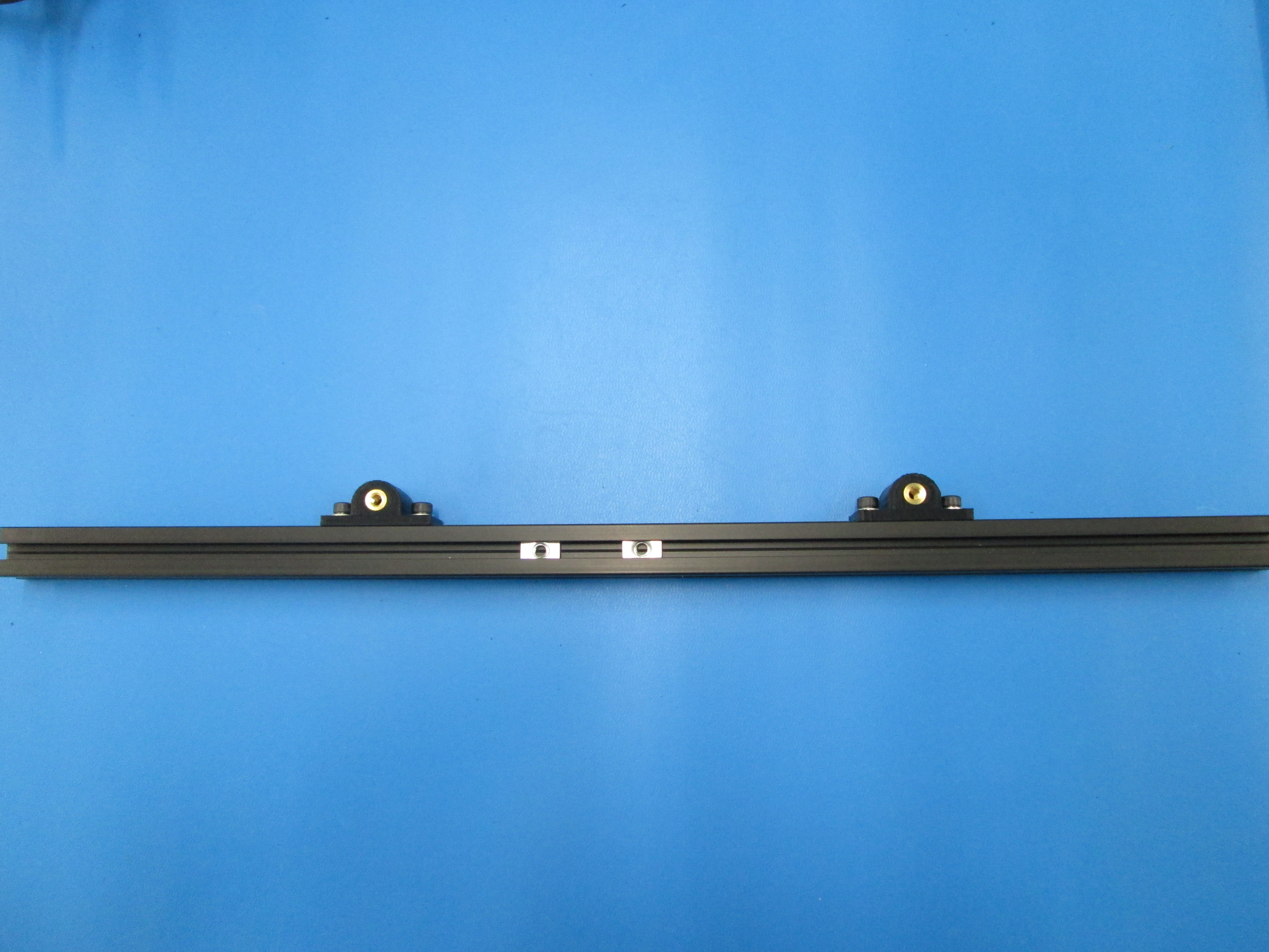
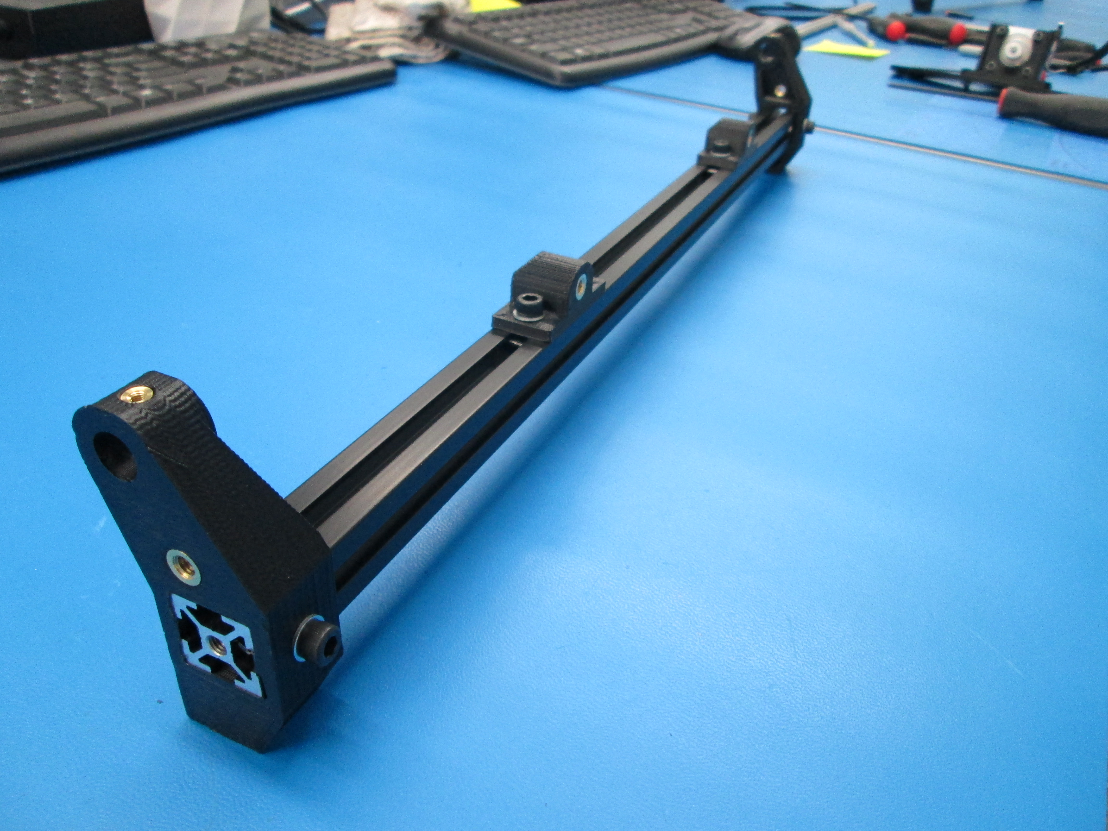
Build 2 of these assemblies. Slide all 4 T-nuts into one side of the double tapped extrusion. Using the M5 x 10 SHCS and M5 Washers, install two Y table mounts onto the extrusion. Location is not important at this point, just be sure the mounts are facing the same direction.
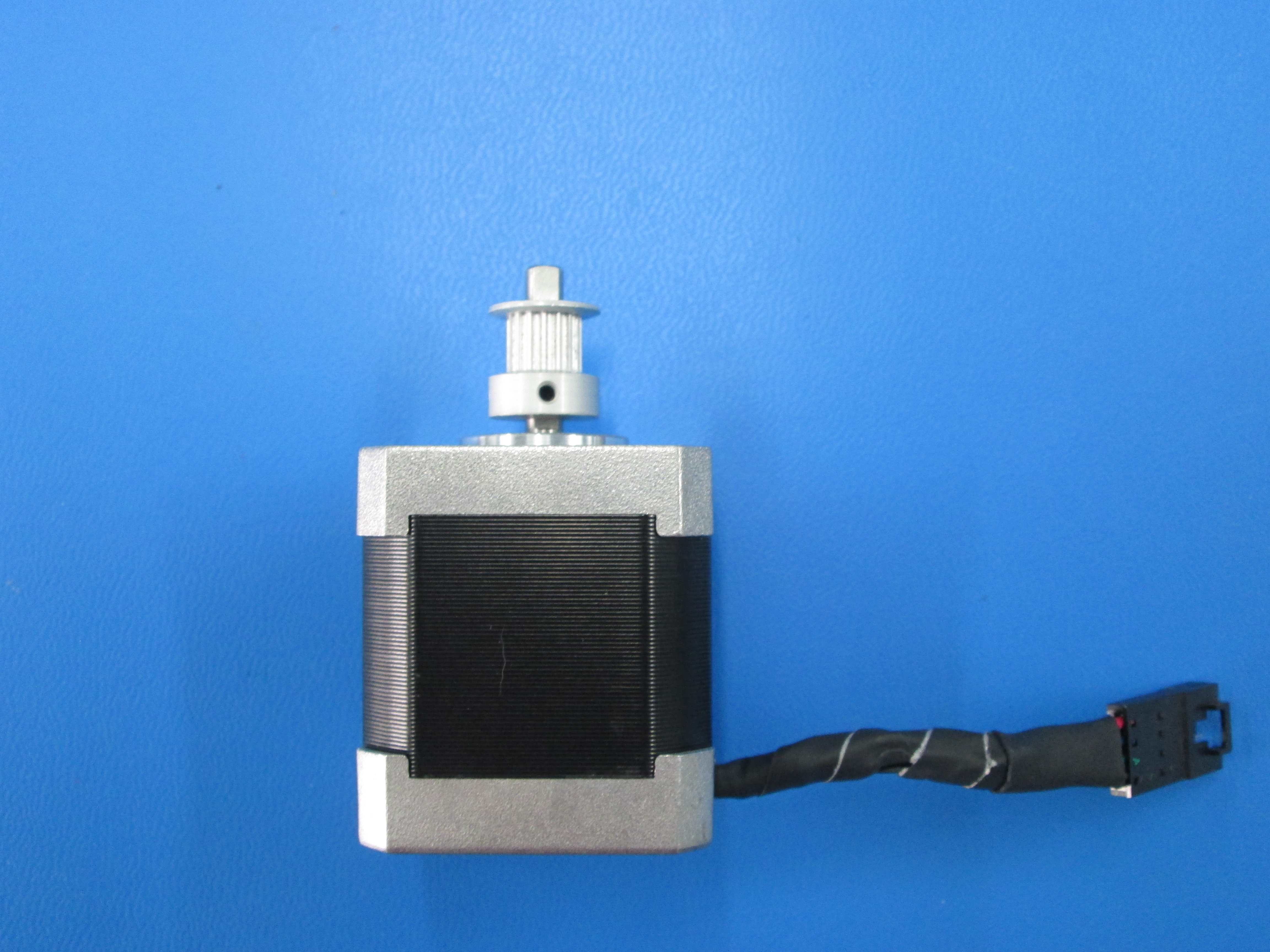
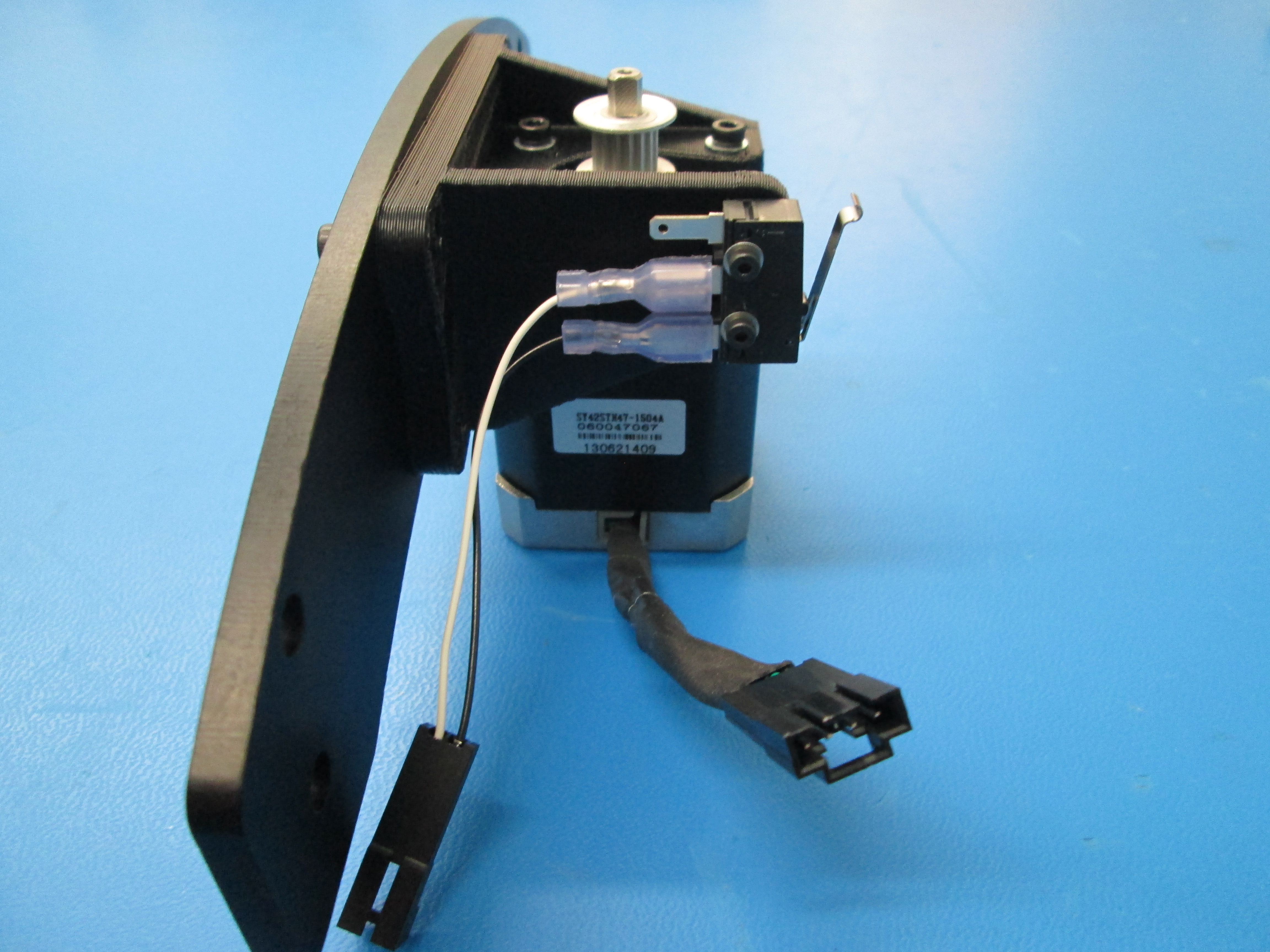
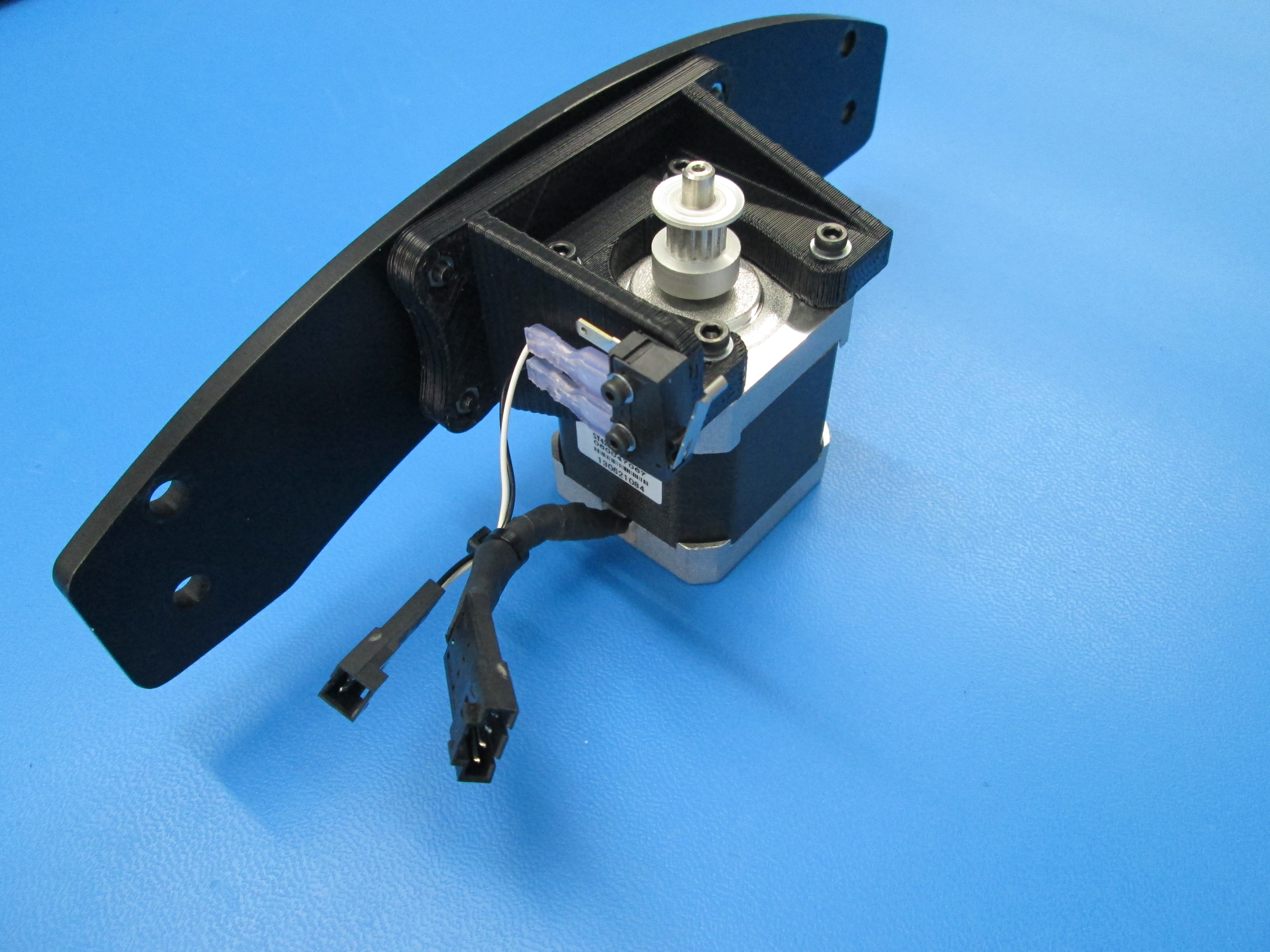
First install pulley onto the motor shaft. Place the pulley onto the shaft approximately 2mm from the motor. Make sure one of the set screws is aligned with the flat side of the motor shaft. Tighten both set screws.
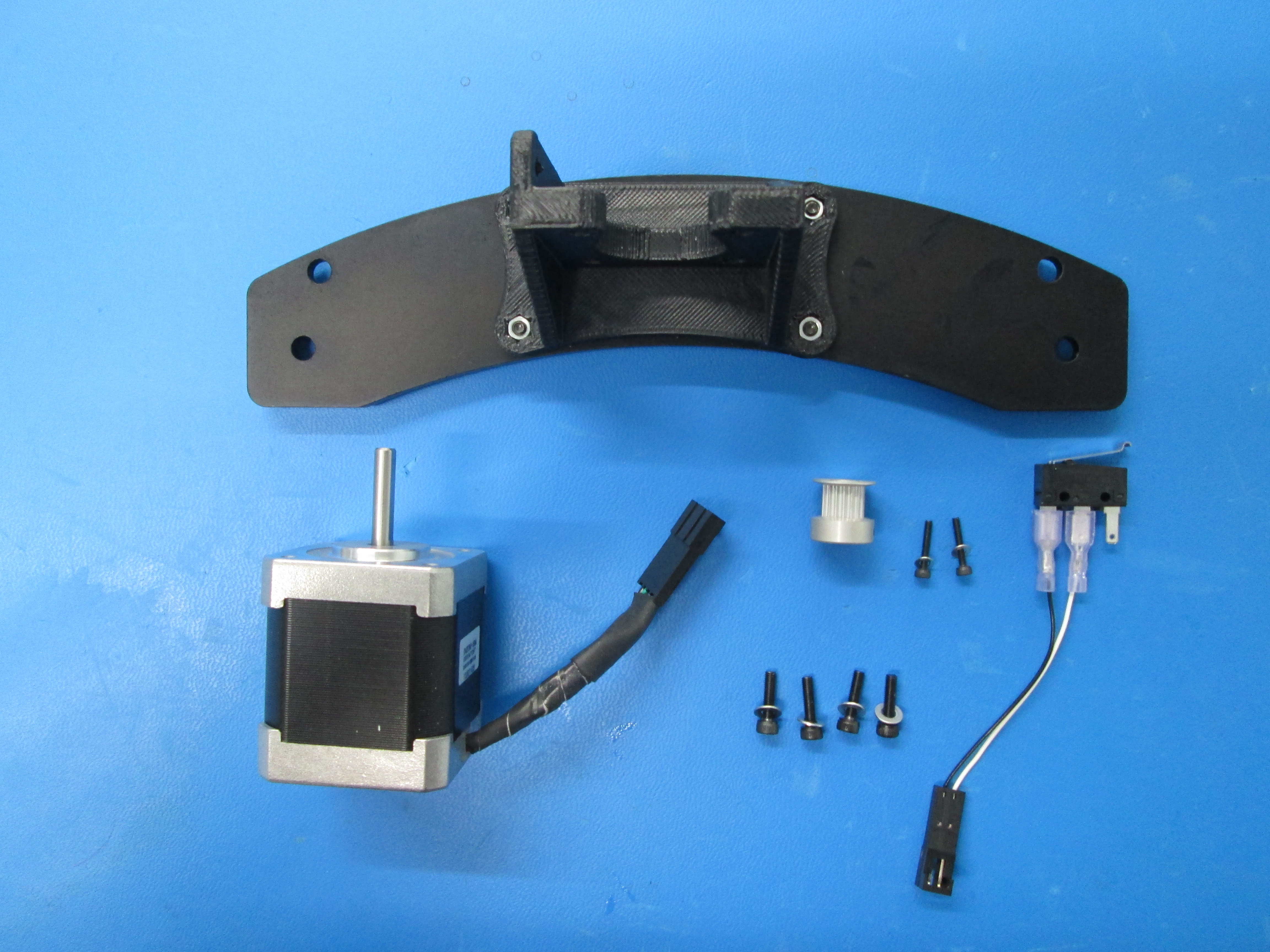
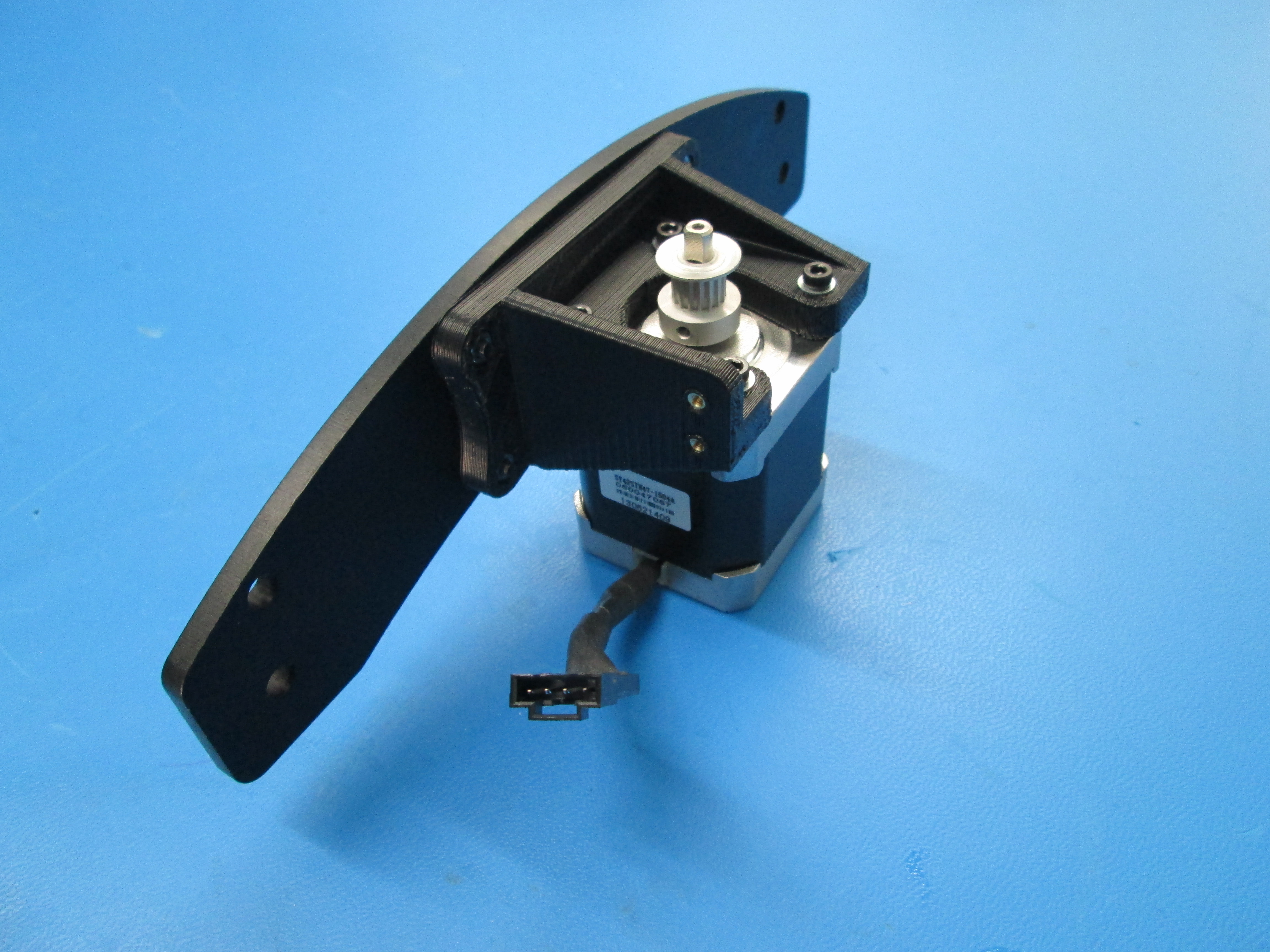
Fasten the motor to the mount using 4 M3 x 12 SHCS with M3 washers, note the orientation of the wires, center the motor on the mount and tighten bolts.
Now attach limit switch with extension to the motor mount using 2 M2 x 12 SHCS with M2 washers, note orientation of switch and wires.
Zip tie motor wire to limit switch extension as indicated.

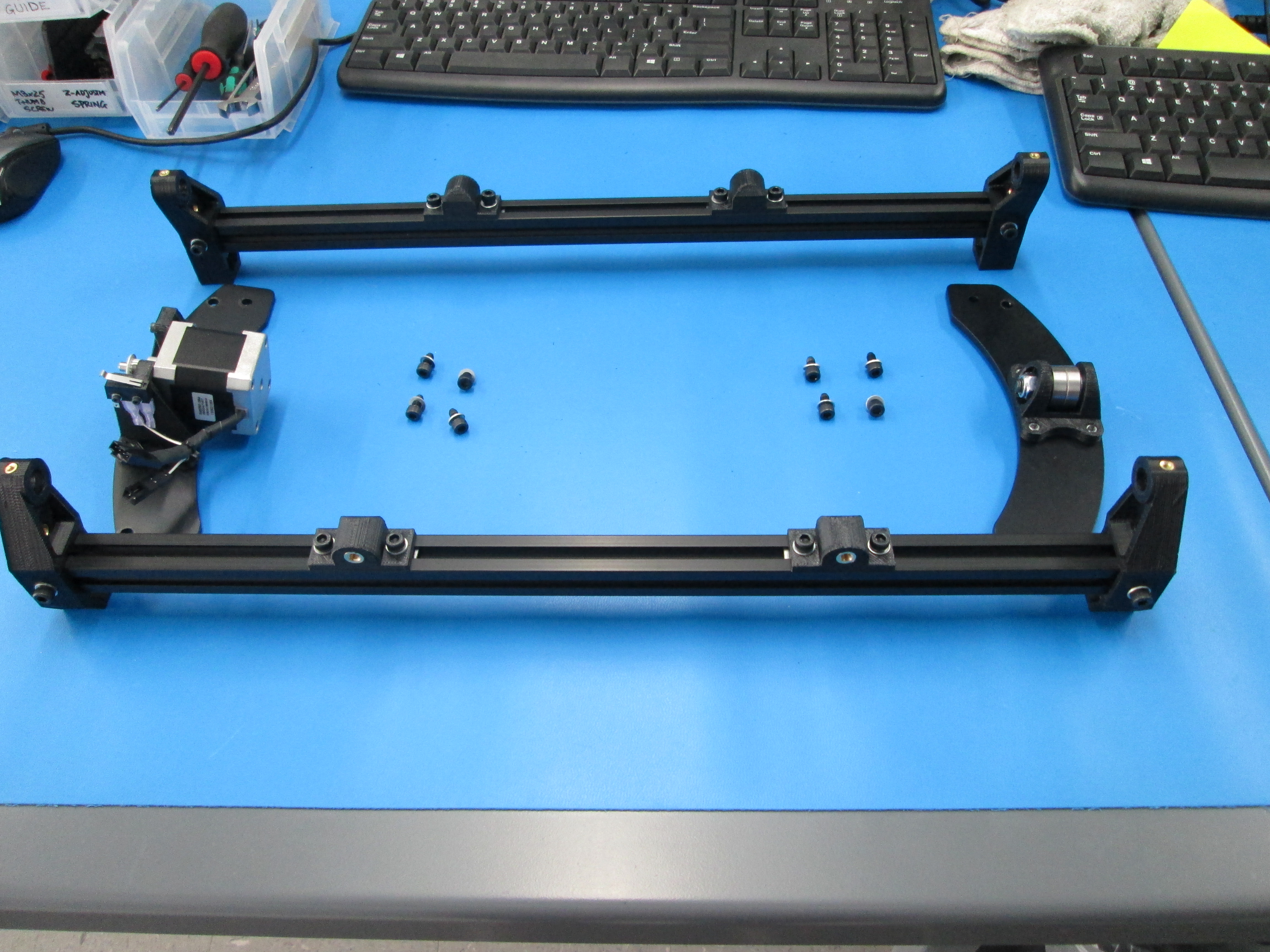
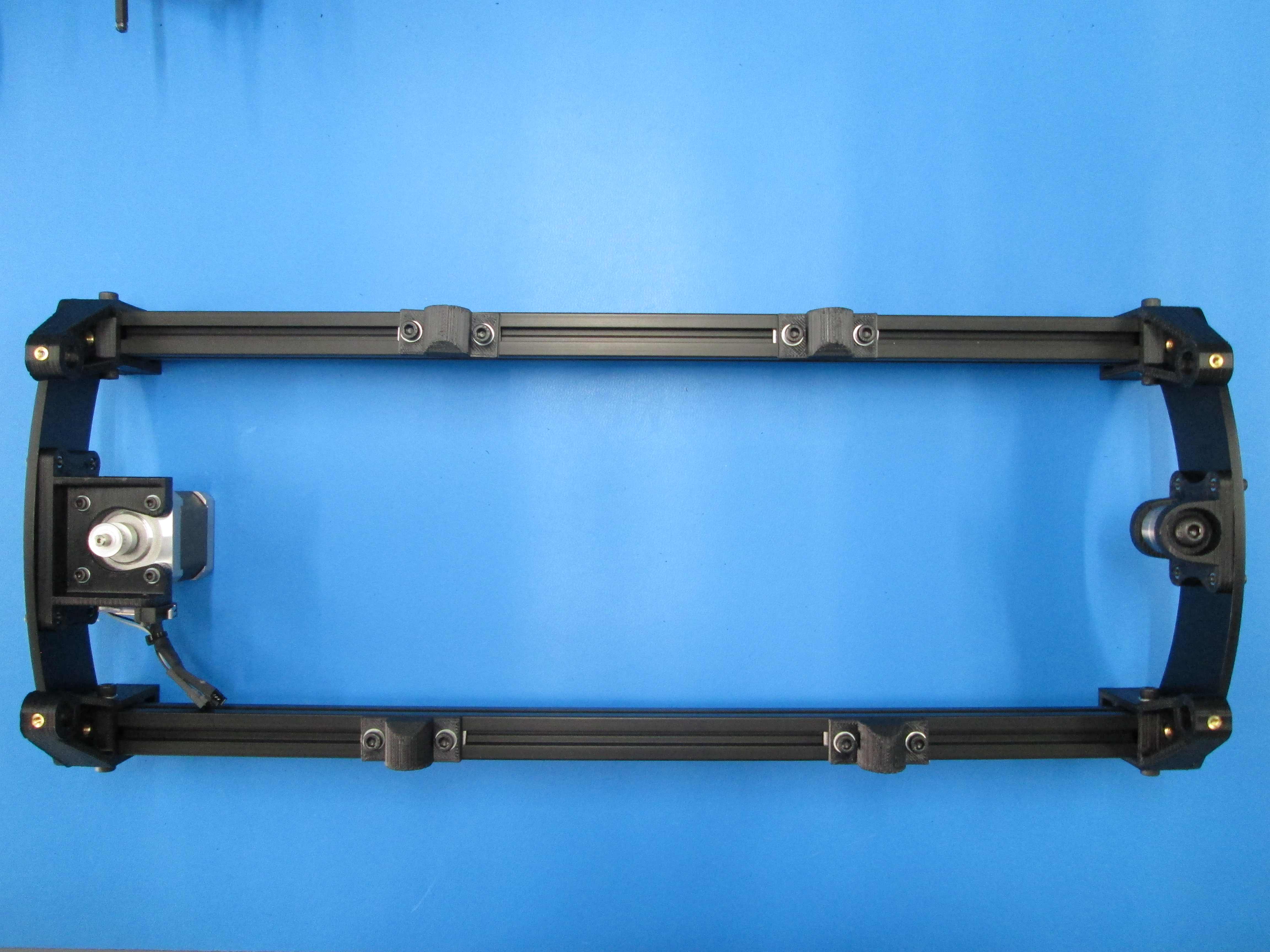
First slide 2 T-nuts into the side of the extrusion, then slide 2 more T-nuts into the opposite side of the extrusion. Note that the top of the extrusion is the side with the table mounts on it. Do this to both extrusions.
Slide a left Y corner onto the extrusion making it flush with the end, use 2 M5 x 10 SHCS with M5 washers and screw them into the T-nuts. The Y corner should be angled inward as shown. Do the same with a right Y corner. Do this to both extrusions. Do not tighten the T-nuts down yet.
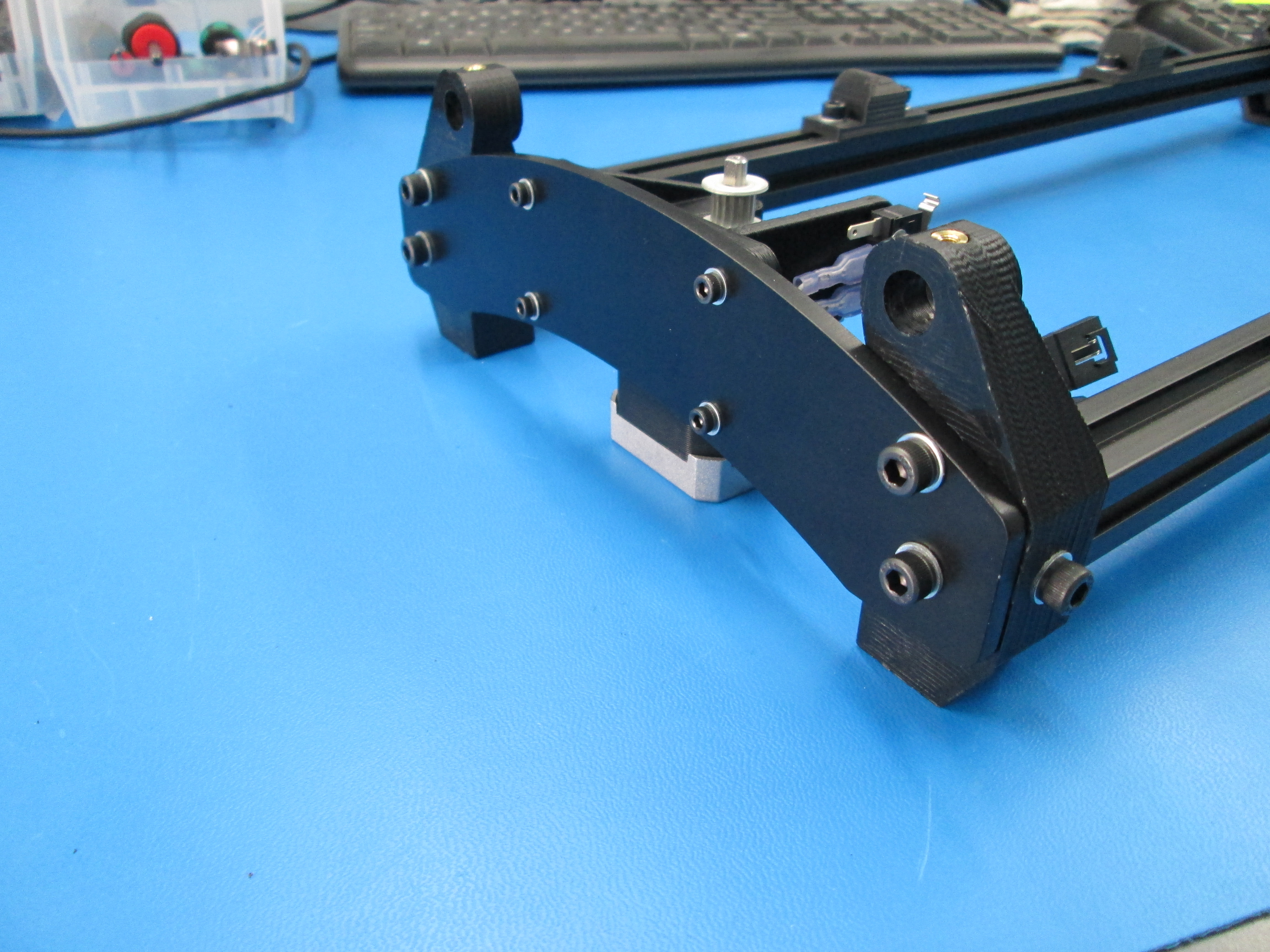
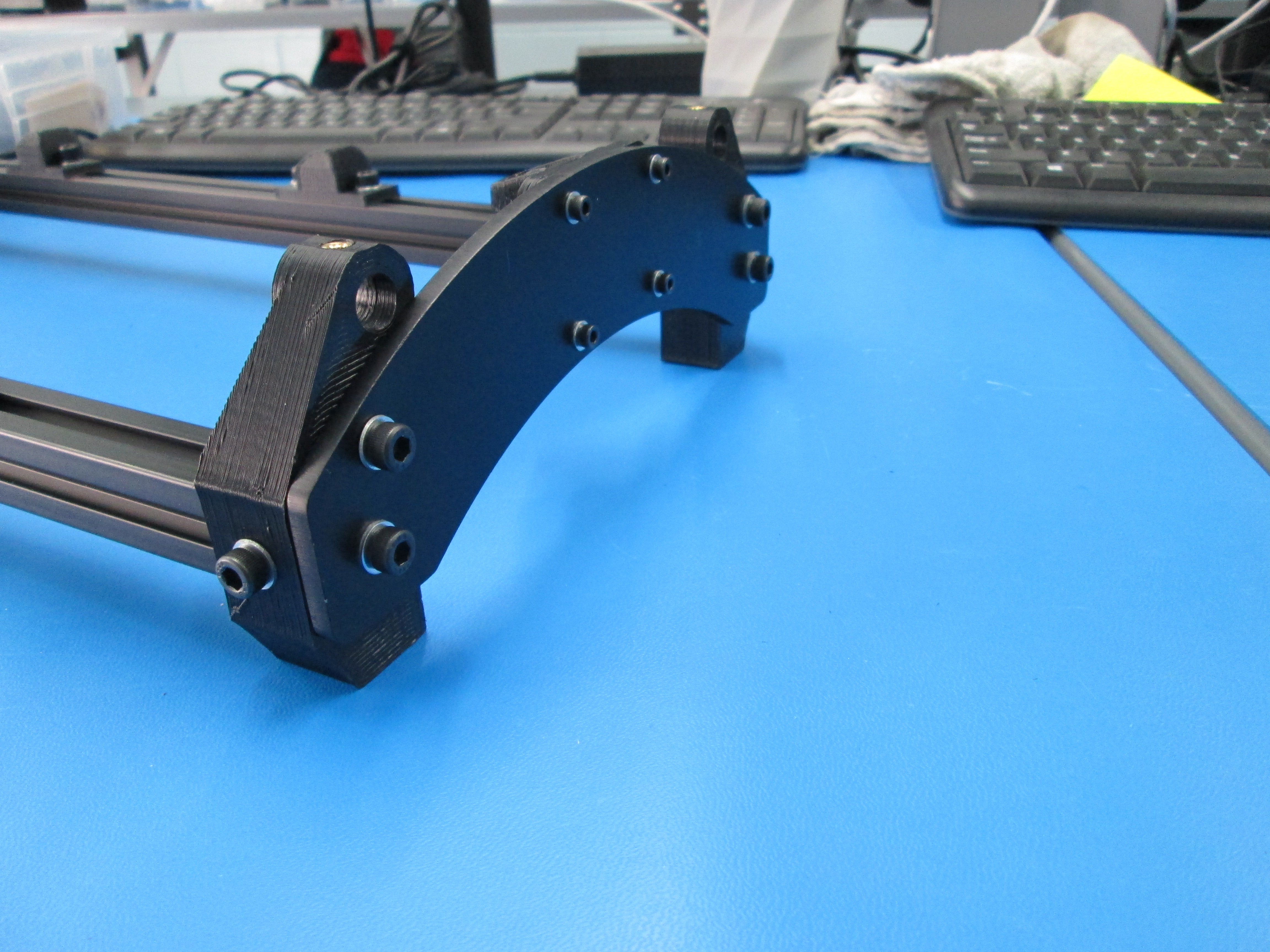
Bolt the Y motor mount end assembly to the Y corners and extrusions using 4 M5 x 10 SHCS with M5 washers, tighten them down. Now do the same for the Y Idler end assembly.
Once everything is square and flush you can tighten down the T-nuts on the side of the Y corners.

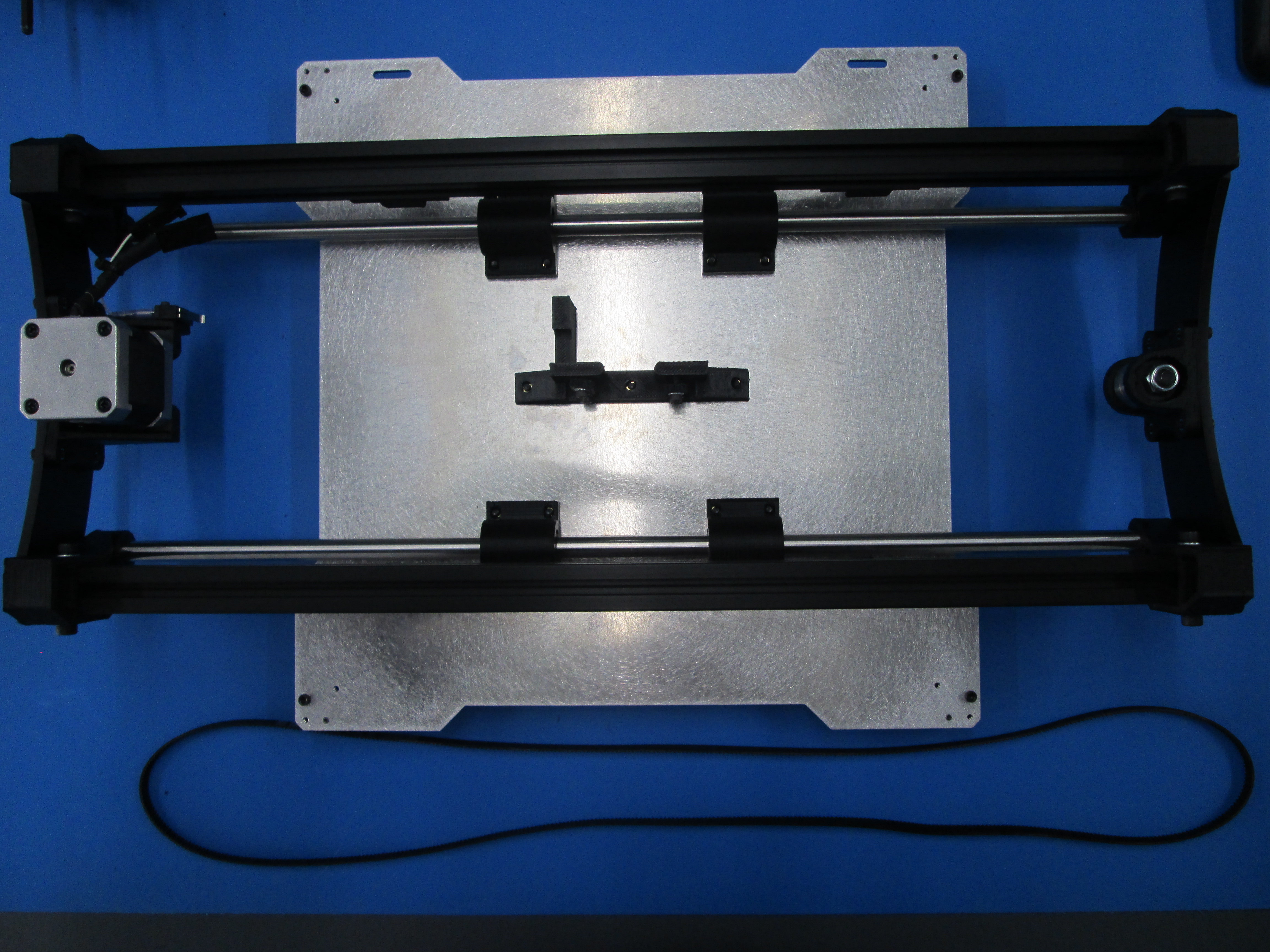
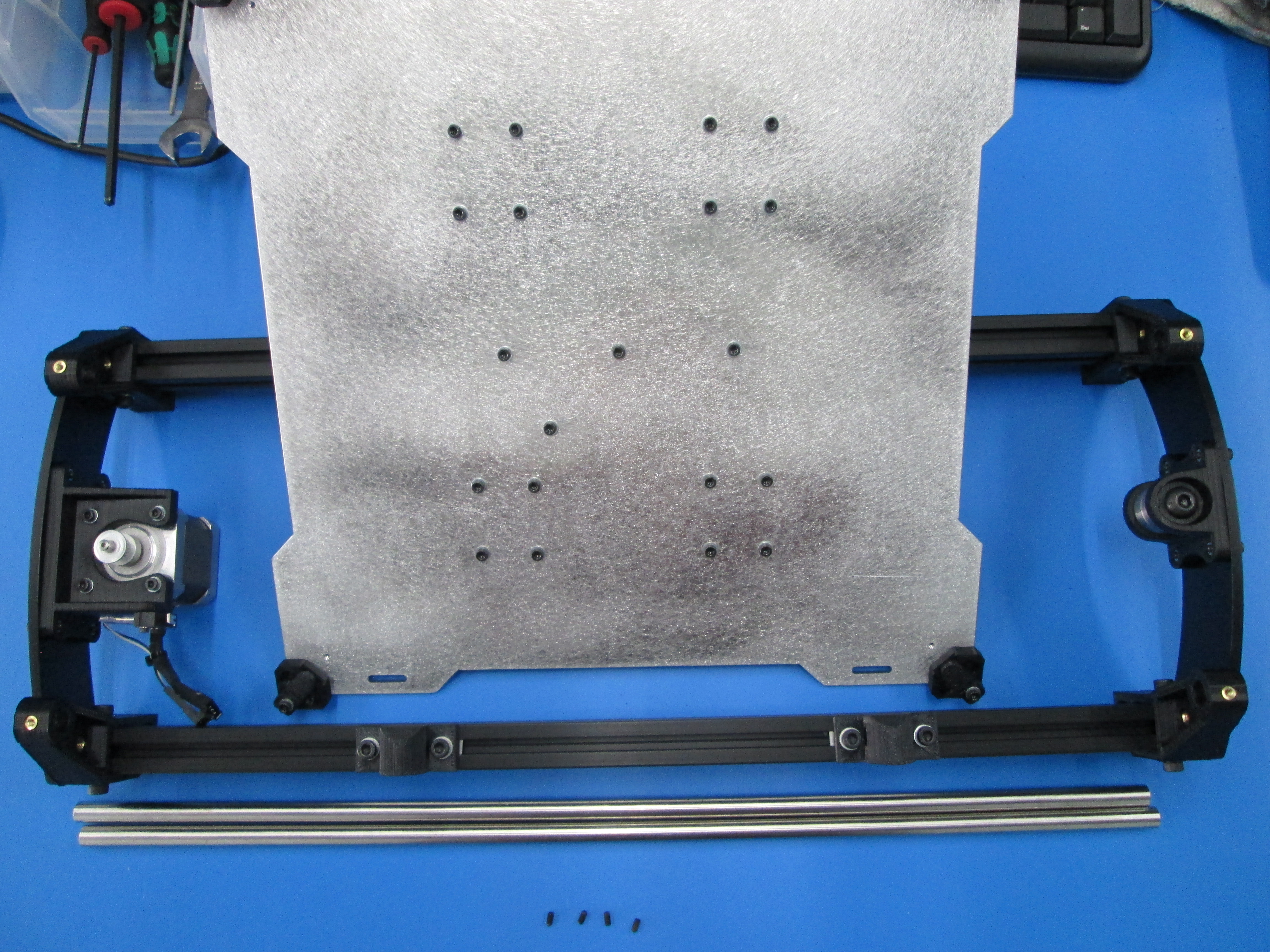
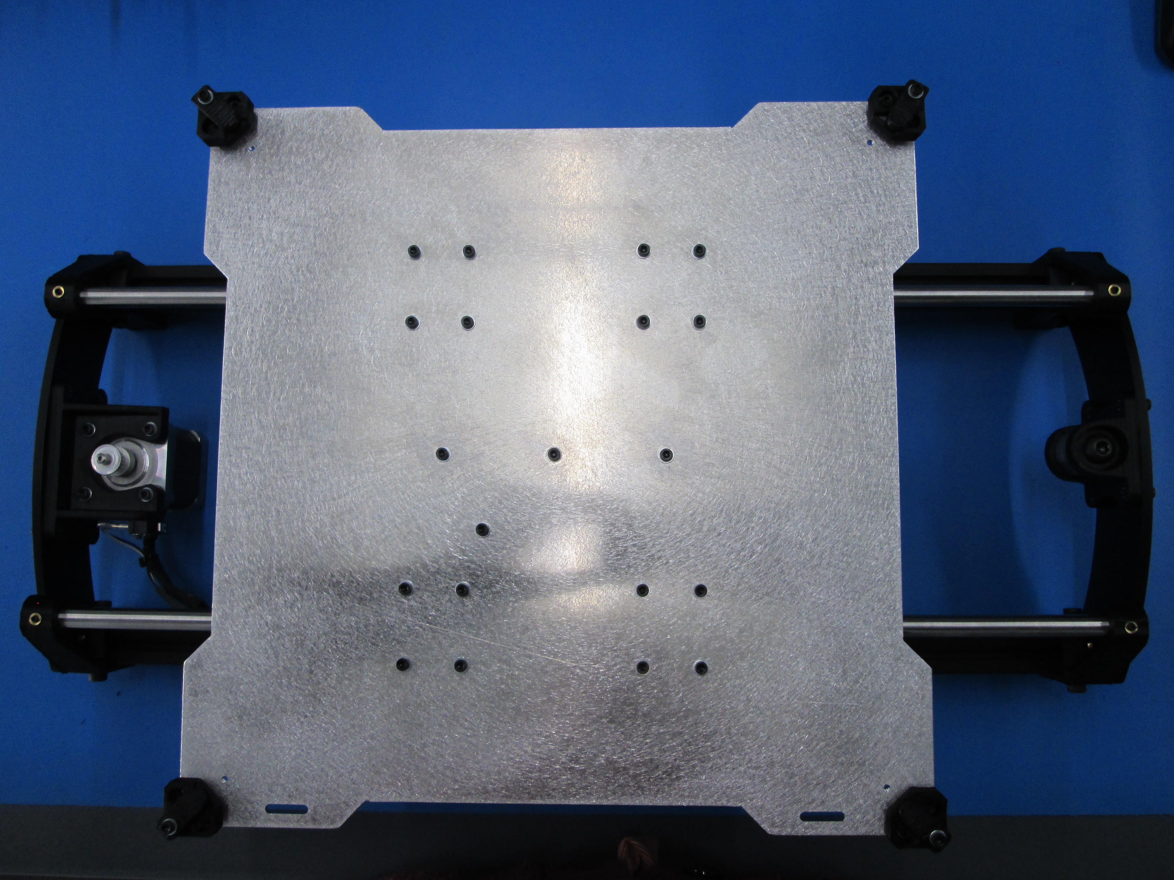
Notice orientation of the Y plate assembly to the Y axis assembly, the slots on the plate must be on the correct side.
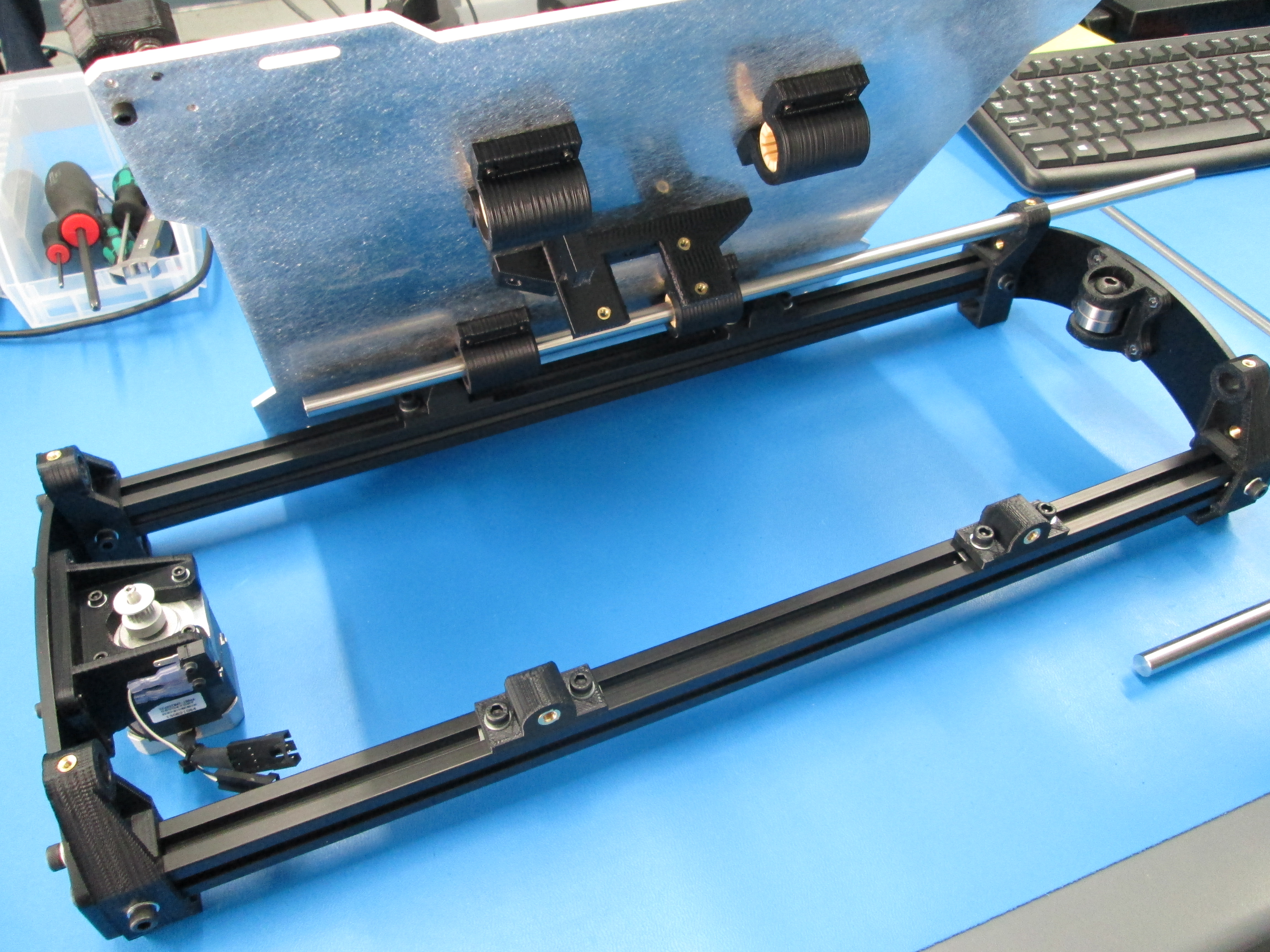
First slide a 10mm smooth rod through the Y end idler assembly then through the bearings on the Y plate assembly then slide the rod through the Y end motor mount. The rod should be flush with both ends.
Repeat with second rod.
Now use 4 M3 x 6 set screws to secure the rods in place. DO NOT over tighten the set screws as it will pull the thermal insert out of the Y corner.
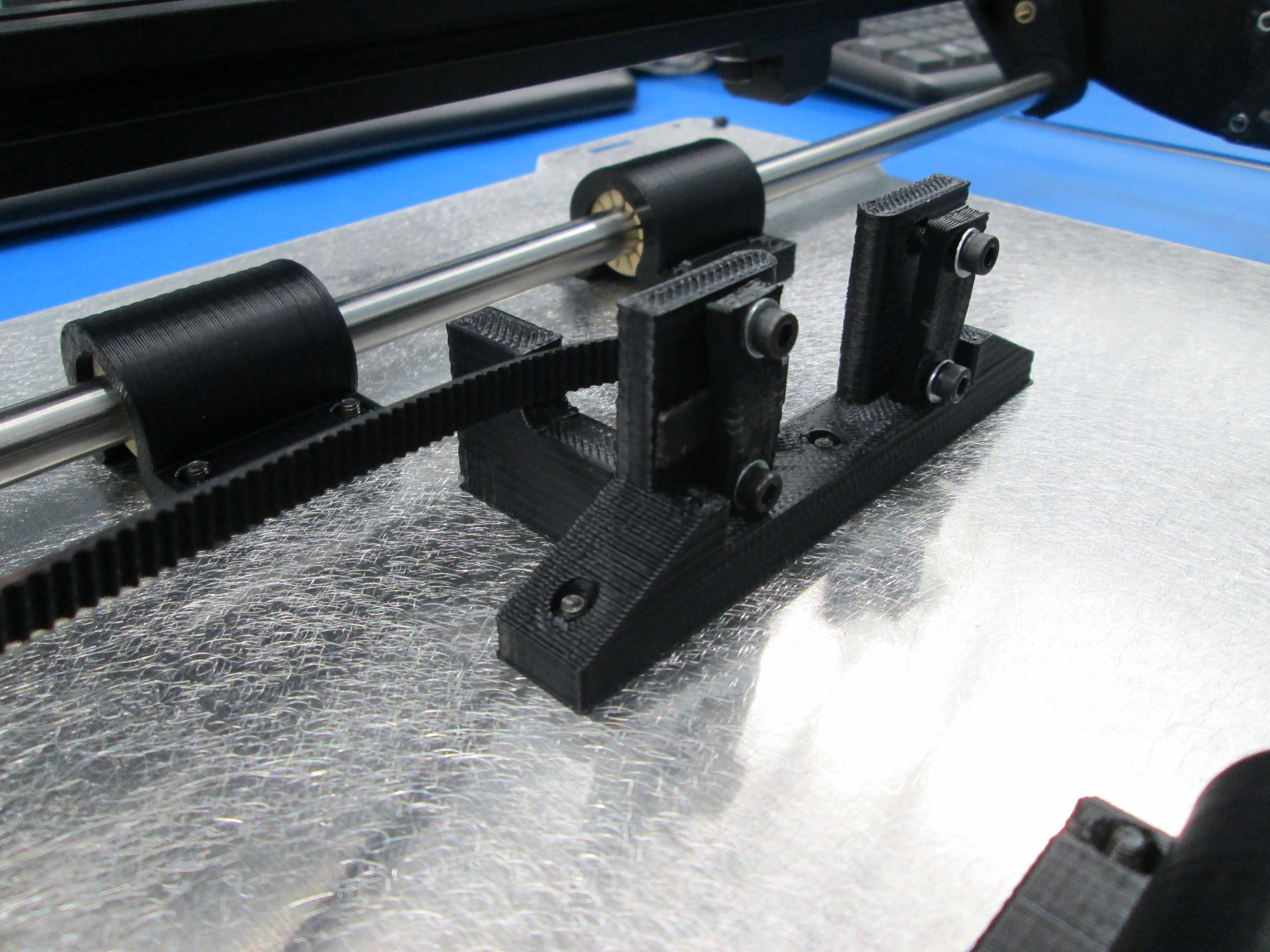
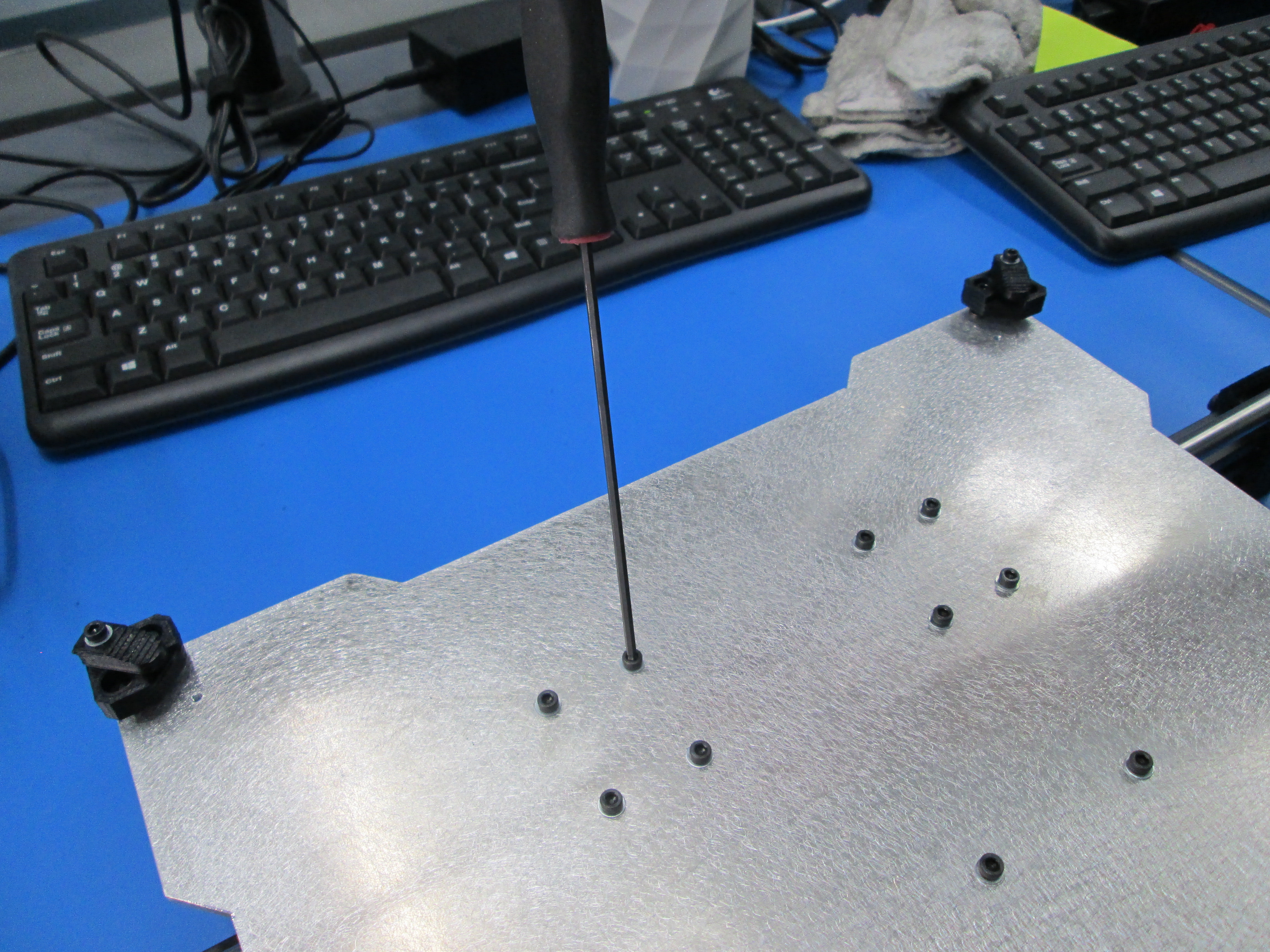
Now you can tighten the bearing holders on the Y plate assembly, making sure you can still slide the Y plate from end to end smoothly.
Does the Y plate assembly have any side to side slop in it? If it does, loosen one of the bushing holders and pull it to the side and re-tighten. Be sure the Y plate still sides back and fourth smoothly.

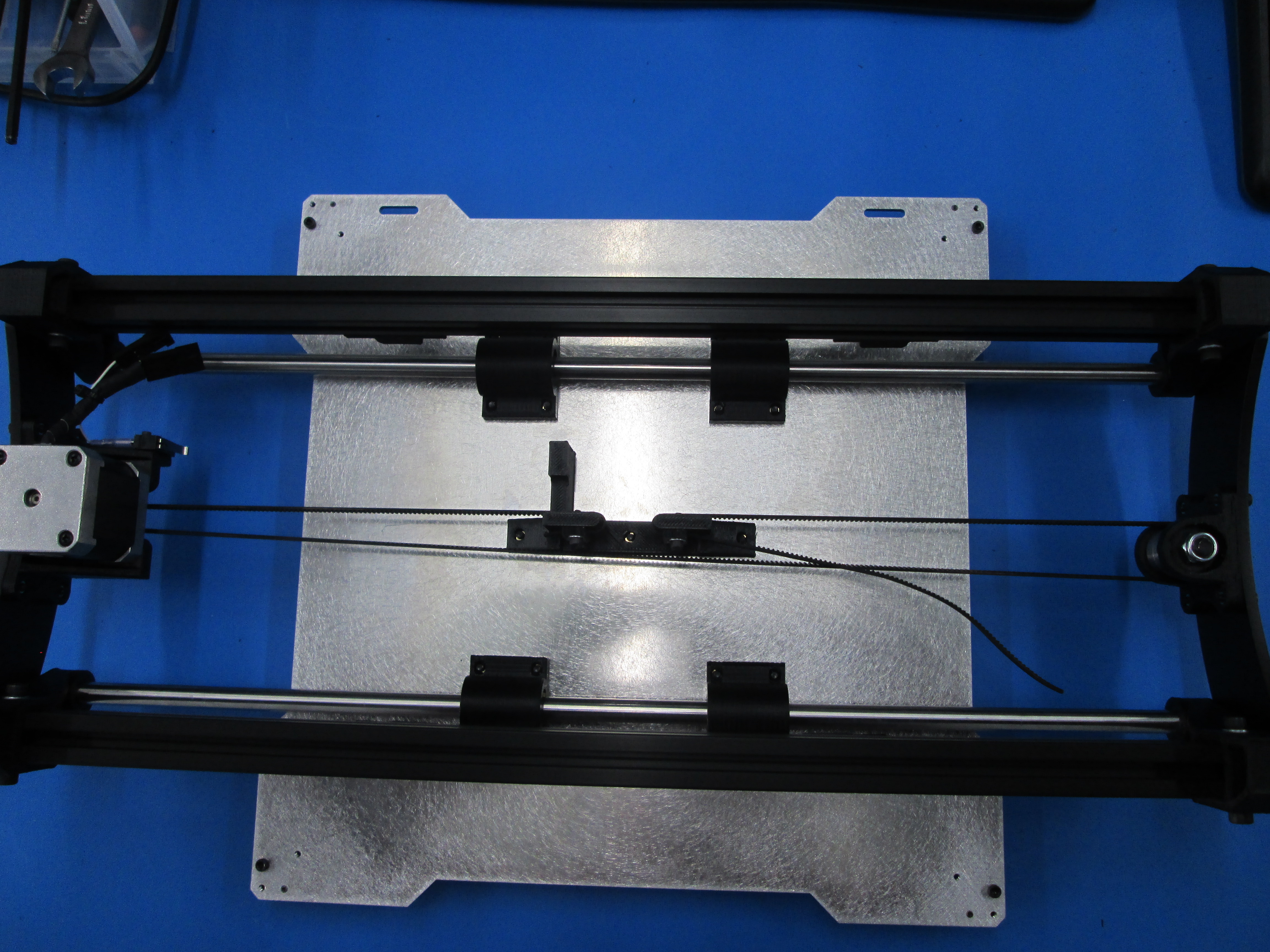
Flip the assembly over.
Cut the belt with the side cutters.
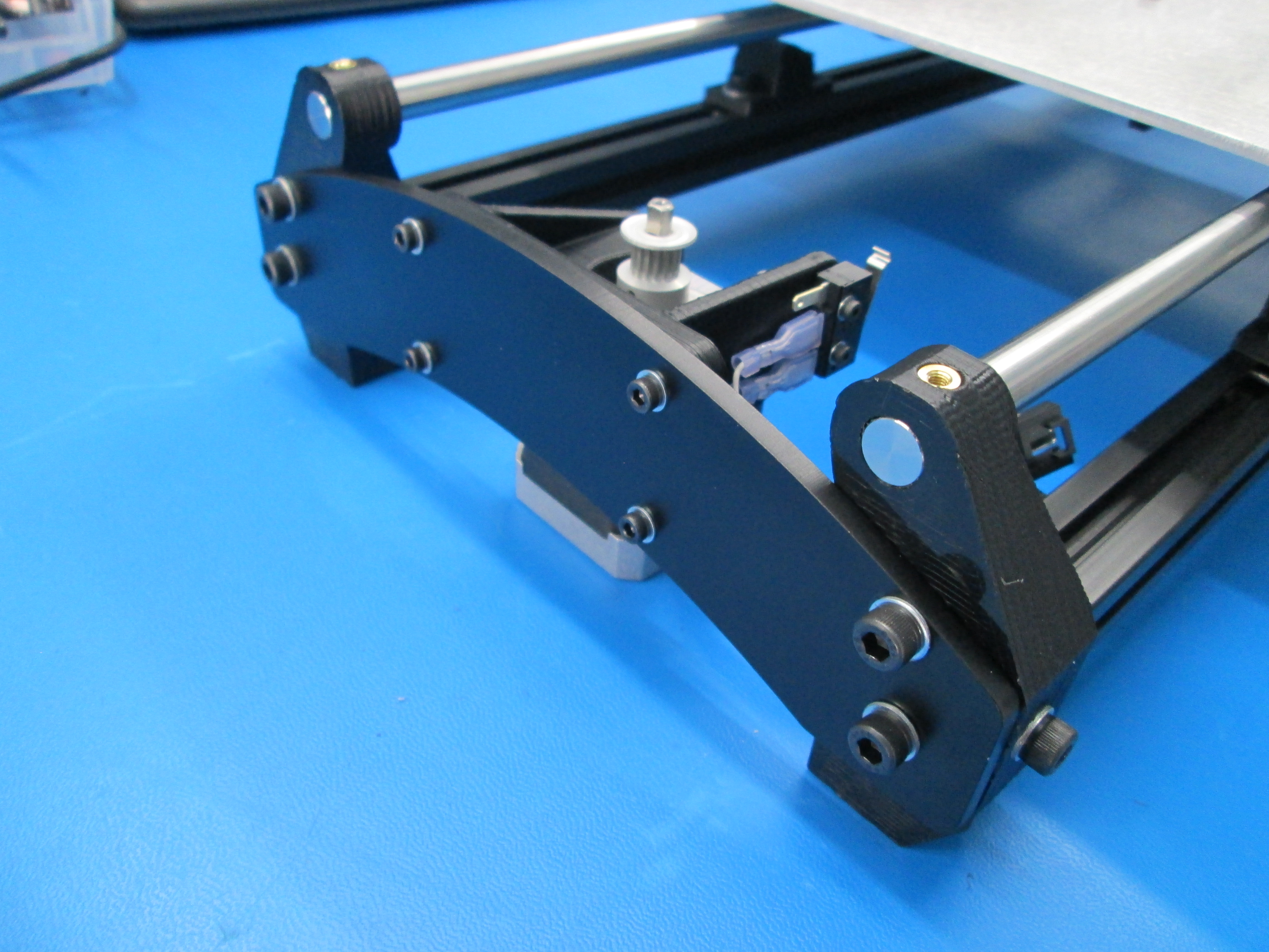
Clamp down the first end of the belt, routing as shown.
Route belt around the motor pulley, through the idler bearing and back through the belt clamp.
Use a pair of needle nose to grab the end of the belt and create a twisting motion that will tension the belt.
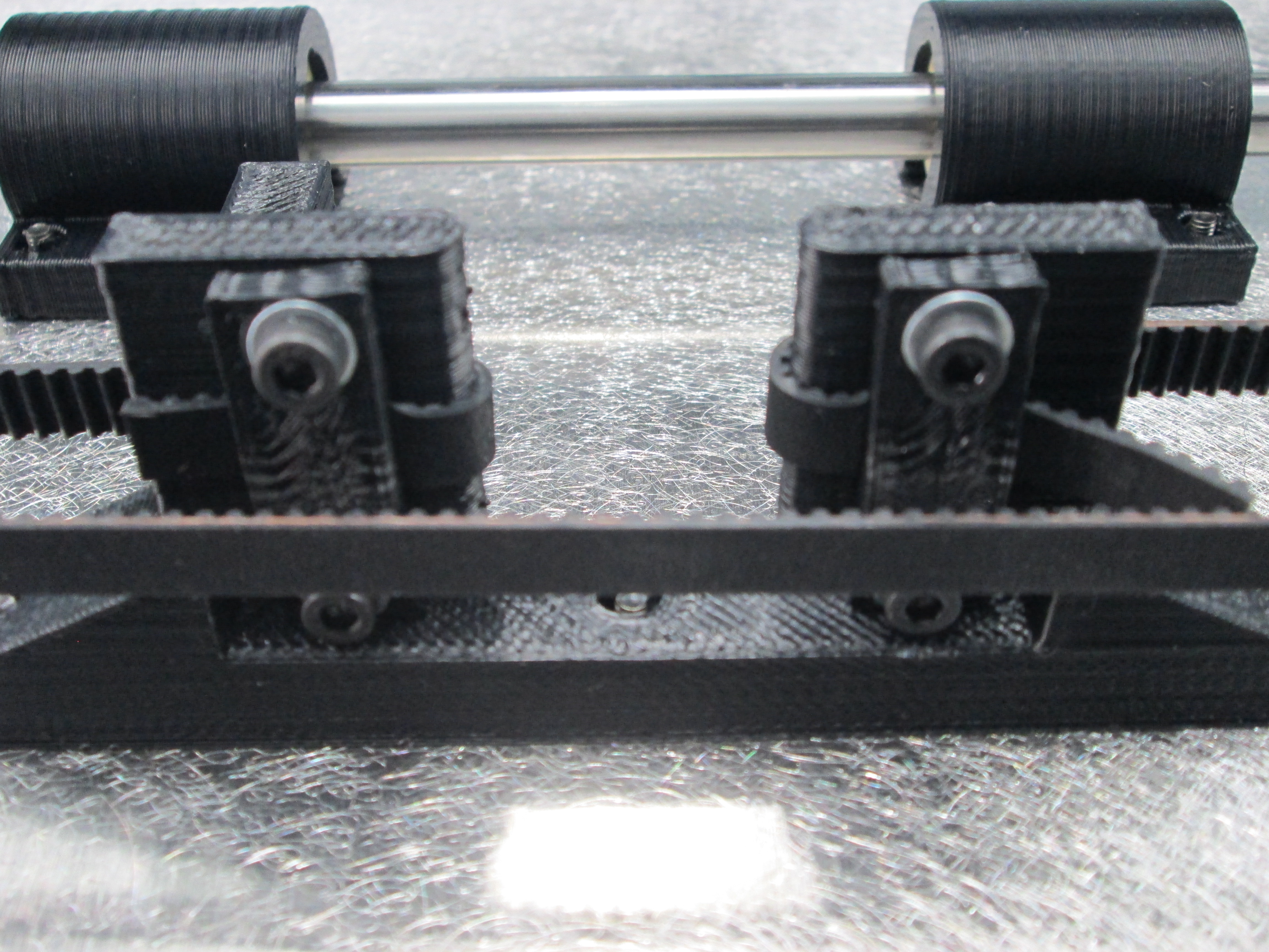
Check if the belt is rubbing on the Y end Idler or the belt mount. If it is, adjust belt position in the clamp or move the motor pulley until there is no interference. Move the Y plate back and forth several times and re-check the belt position, adjust if necessary.
Trim off the ends of the belt short enough they don't rub the belt when the plate assembly is moved back and forth.