Open HardwareAssembly Instructions
Guides for installation and assembly of the LulzBot line of products made by FAME 3D LLC.
Guides for installation and assembly of the LulzBot line of products made by FAME 3D LLC.
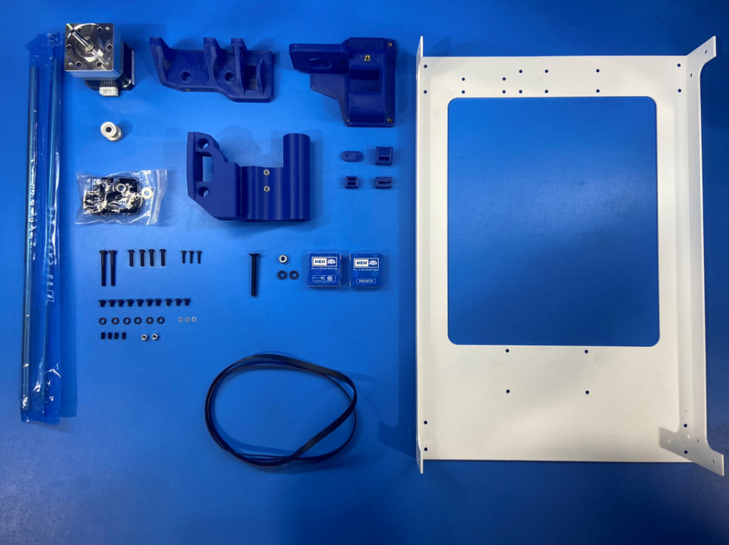
1x- [EL-MT0056] Moons Motor, Gear Ratio 5:1
1x- [HD-BL0033] Single Sided Neoprene Belt, 744mm
4x- [HD-BT0012] M3x6 Set Screw, Black-Oxide
2x- [HD-BT0042] M3x30 SHCS, Black-Oxide
3x- [HD-BT0107] M2x10 SHCS, Black-Oxide
10x- [HD-BT0128] M3x6 FHCS, Black-Oxide
4x- [HD-BT0146] M3x12 BHCS, Black-Oxide
1x- [HD-BT0216] M5x40 FHCS, Black-Oxide
1x- [HD-MS0033] 16 Teeth, Timing Pulley
2x- [HD-MS0411] Premium Two Side Rubber Sealed Bearing
1x- [HD-MS0412] Smooth Idler Pulley Wheel Kit
2x- [HD-NT0001] M3 Locknut
1x- [HD-NT0057] M5 Locknut
2x- [HD-RD0078] Hardened Steel Linear Rod 315mm
3x- [HD-WA0012] M2 Washer, Zinc
6x- [HD-WA0038] M3 Washer, Black-Oxide
1x- [PP-FP0169] Mini Right Side - White
1x- [PP-GP0131] X End Idler
1x- [PP-GP0312] Z Upper Right
1x- [PP-GP0313] Z Lower Right
2x- [PP-GP0348] Printed Threaded Spacer
1x- [PP-GP0511] Belt Tensioning Collar
1x- [PP-GP0512] Z Belt Clamp
1x- [PP-GP0645] Belt Tensioner Block
1x- [PP-GP0680] U Channel Belt Clamp
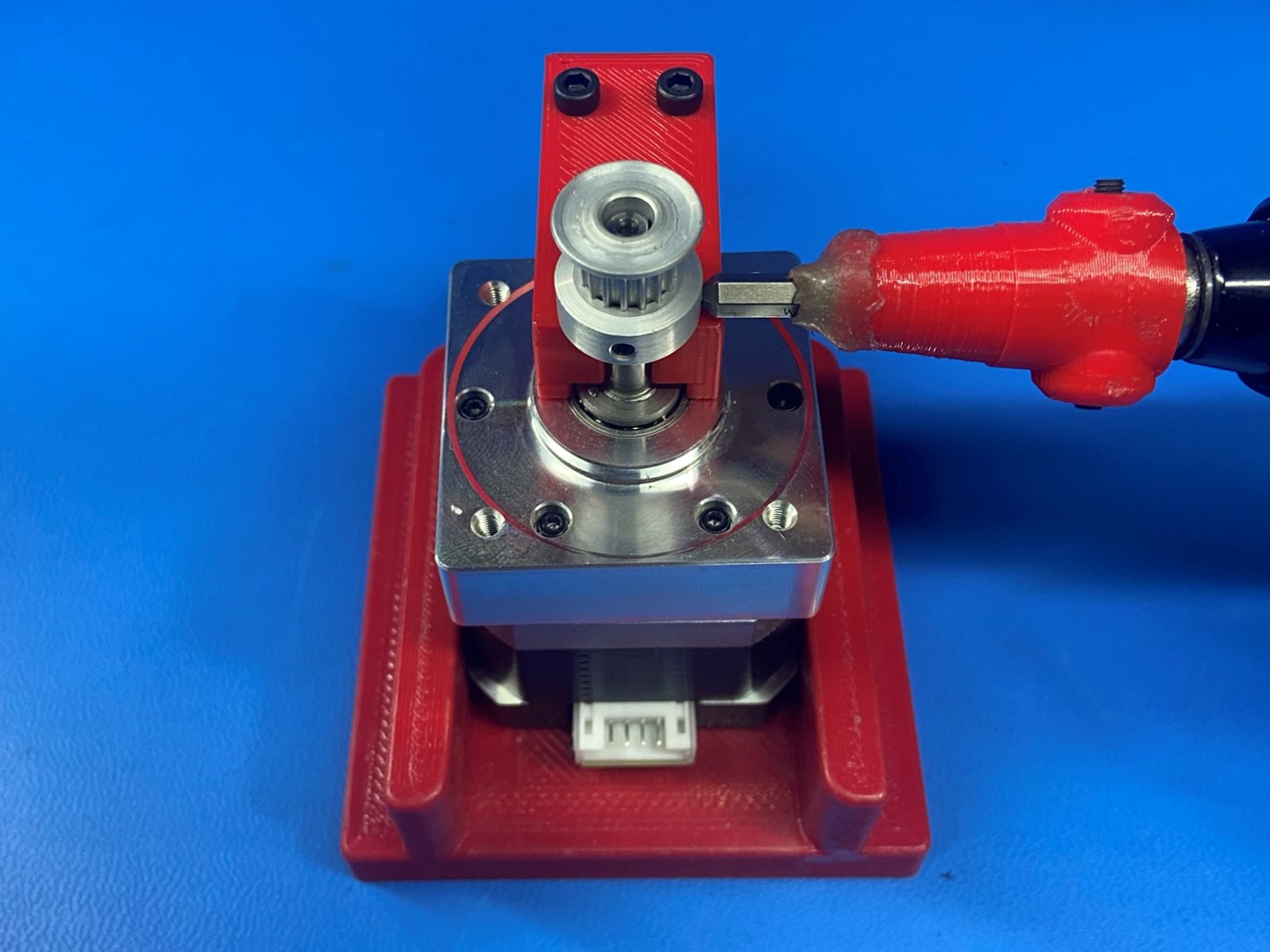
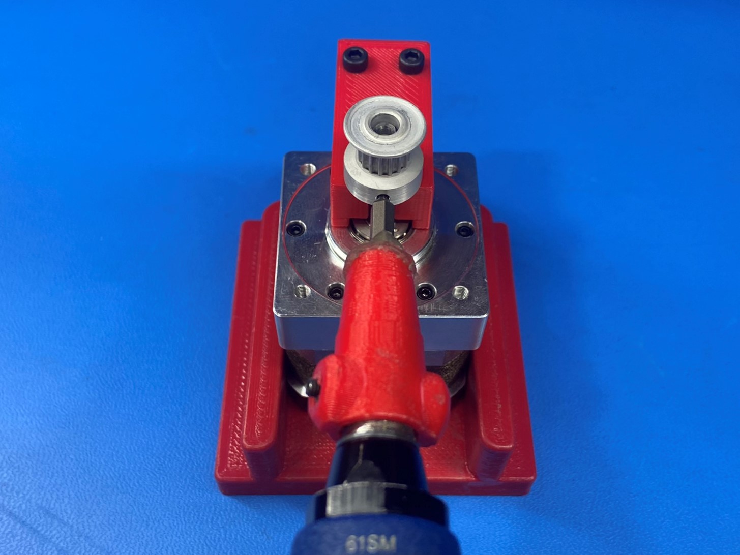
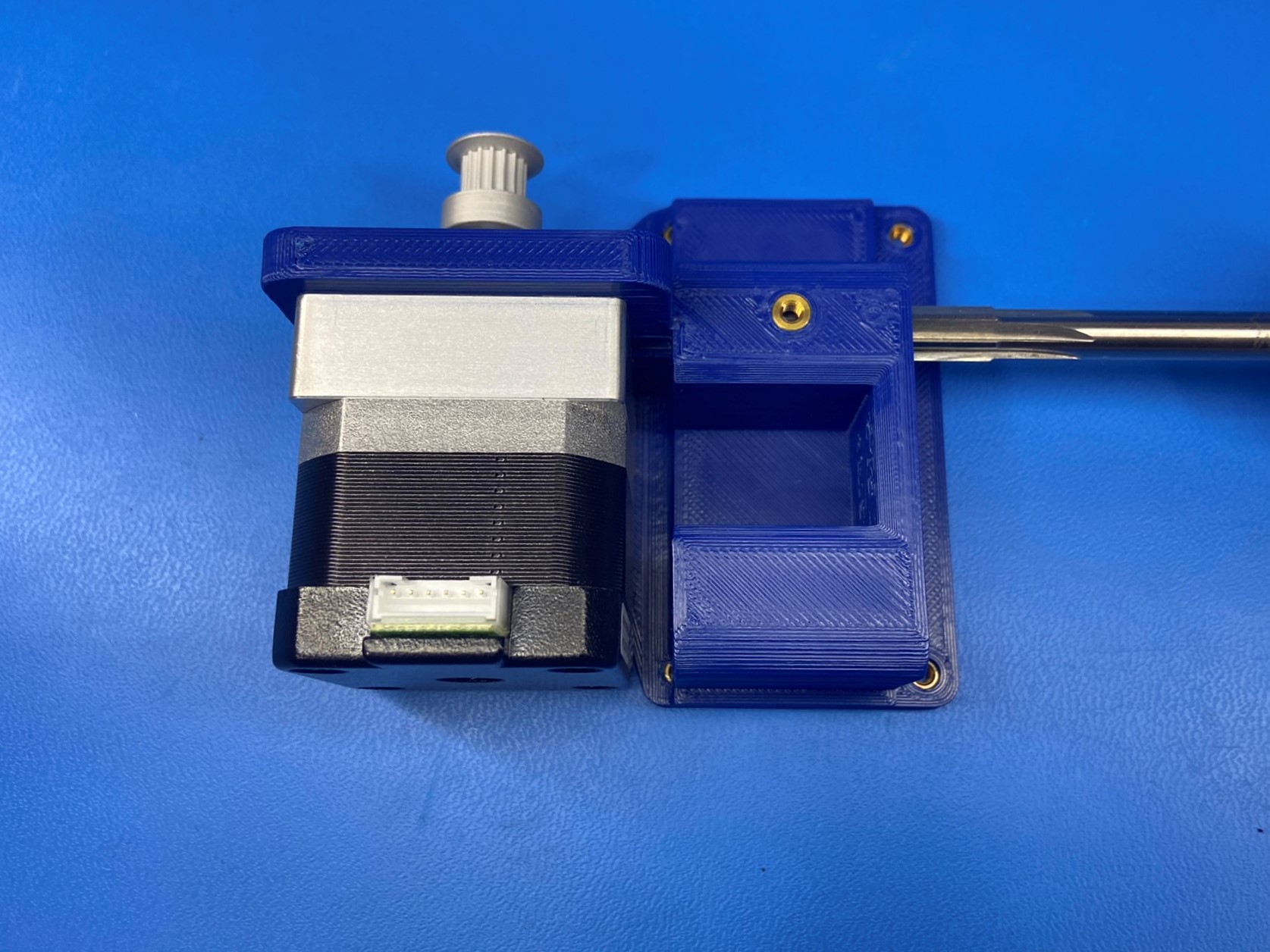
Attach a timer pulley [HD-MS0033] to the motor with a 5:1 gear ratio [EL-MT0056] using the Bio motor jig. Verify that the flat portion of the motor shaft lines up with one of the set screws on the pulley. Then tighten both set screw to 3 in*lbs.
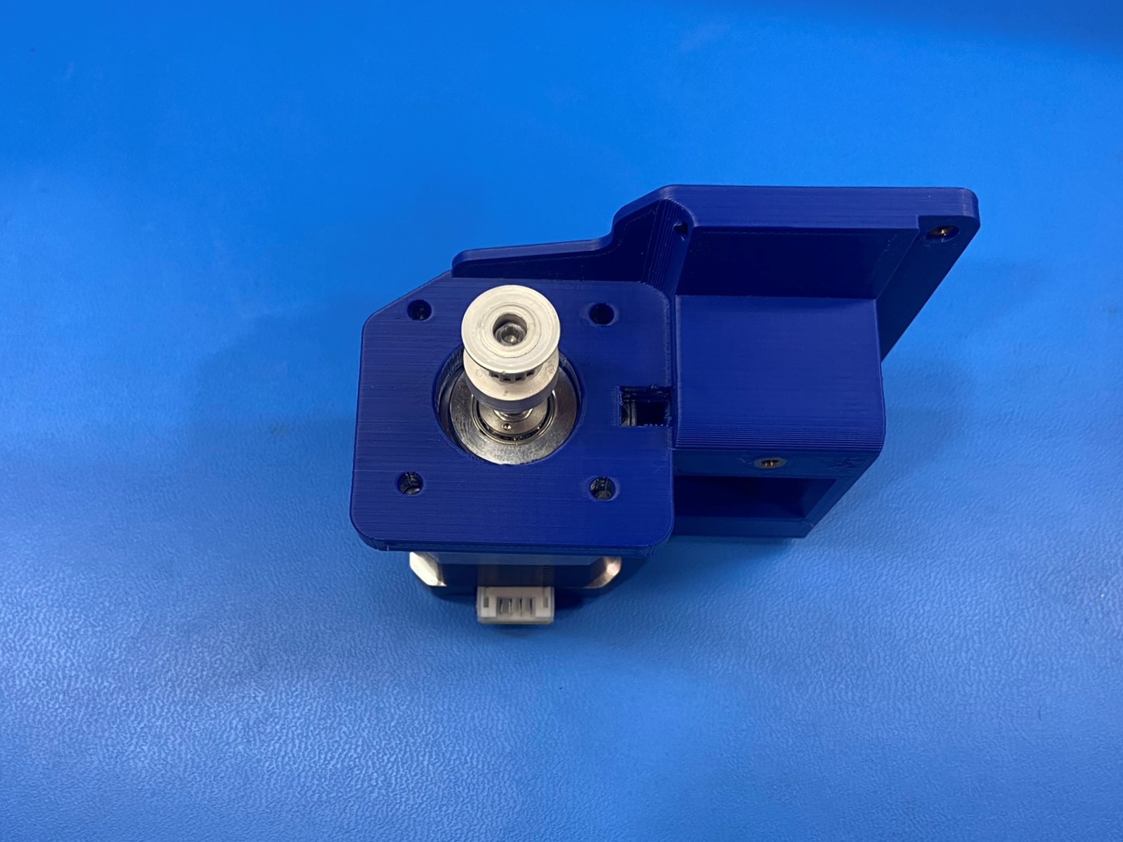
Align the Z motor with the Z lower right [PP-GP0313] the motor connector will face away from the flat side of the Z lower right.
Attach the motor to the Z lower right using 4x M3x12 BHCS [HD-BT0146] with 4x M3 washers [HD-WA0038].
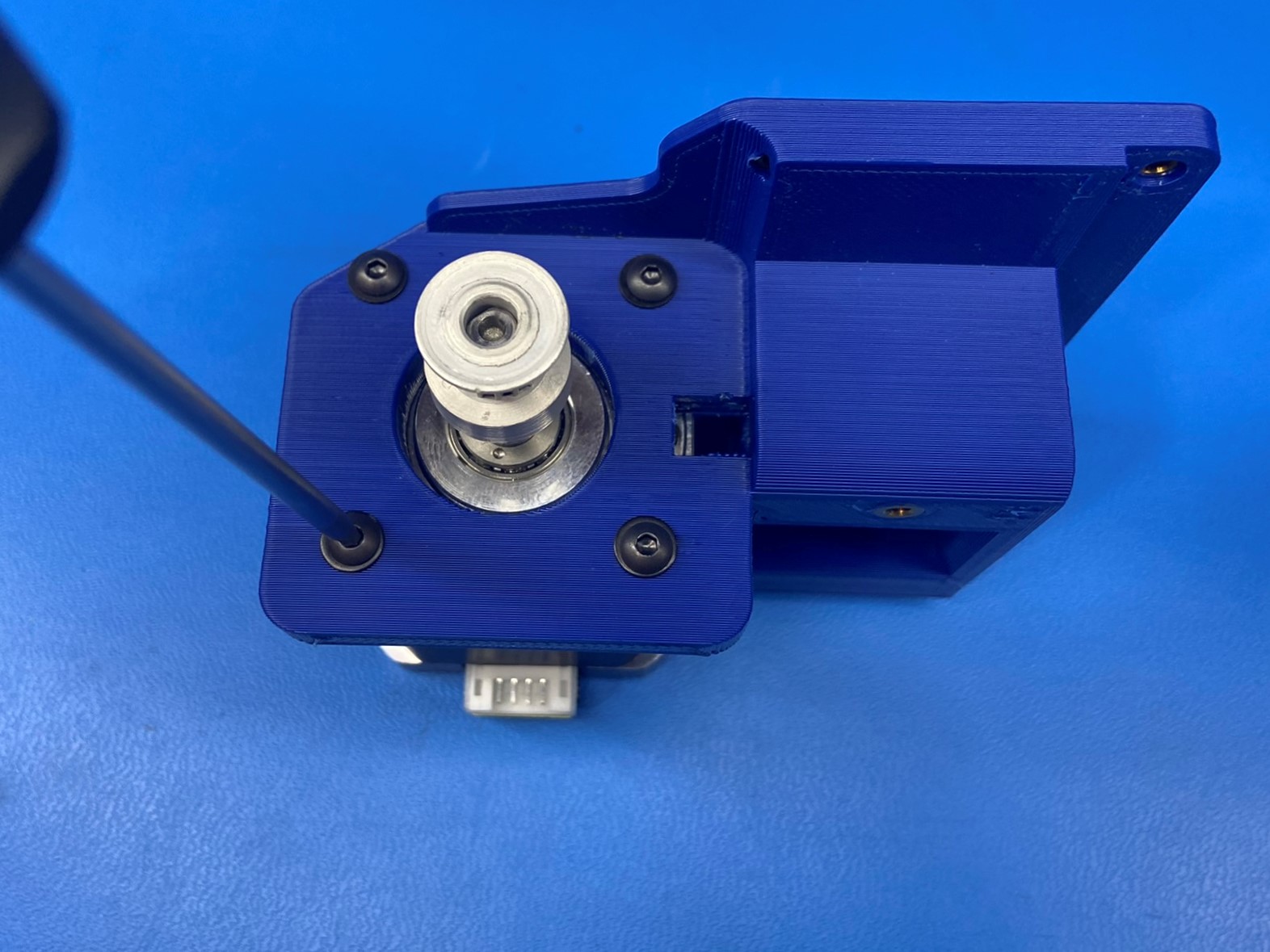
Using an 8mm part reaming tool, ream the 8mm smooth rod hole on the Z lower printed part that has the M3 insert.
Take care to keep the tool straight and to not remove too much material which would result in a loose fitting rod. Do Not touch the reaming tool to the motor.
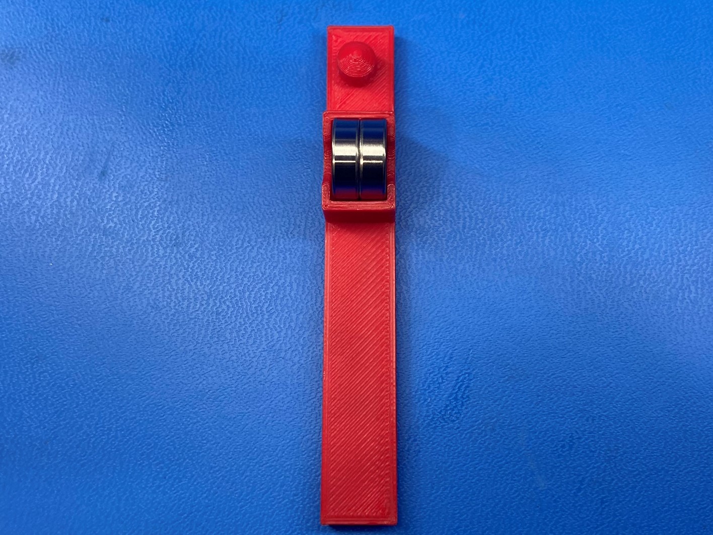
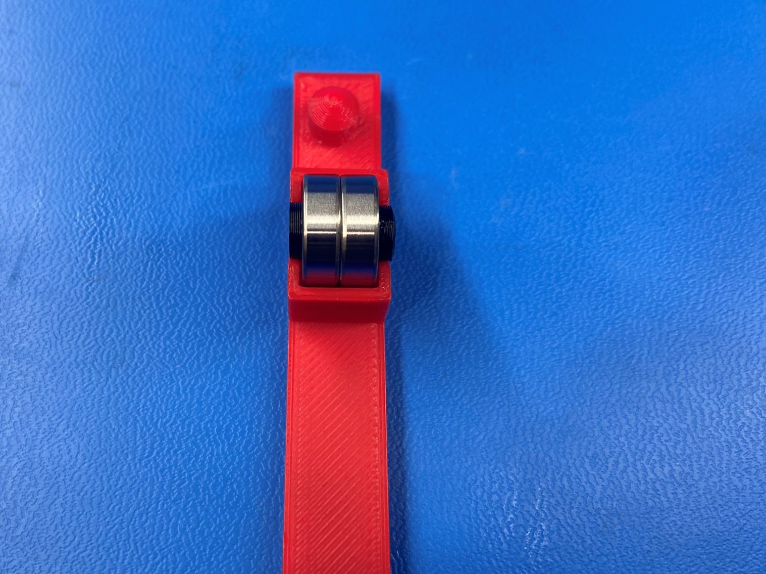
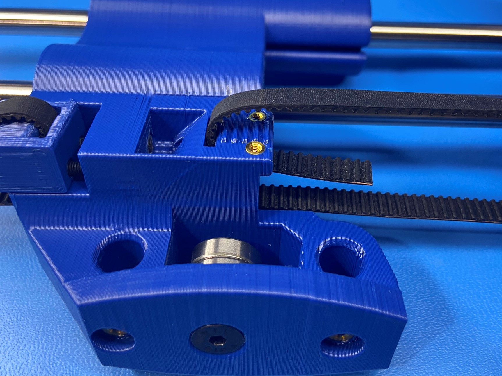
Place two bearings [HD-MS0411] inside the X end idler jig, then place two printed threaded spacers [PP-GP0348] on each side of the bearings.
Then take the X end idler jig and align it with the X end idler, and thread 1x M5x40 FHCS [HD-BT0216] through the spacers and bearings.
Place 1x M5 locknut [HD-NT0057] inside the hex hole on the X end idler and fasten the M5x40 FHCS into the M5 locknut. Make sure the bearings are able to freely spin, if they are tight loosen the screw
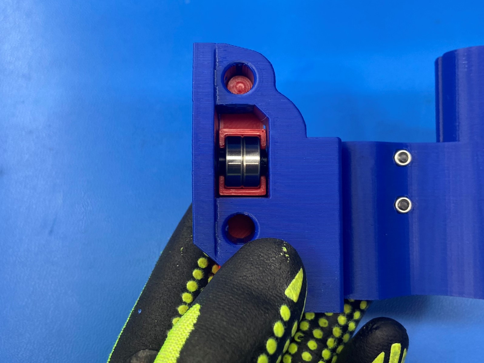
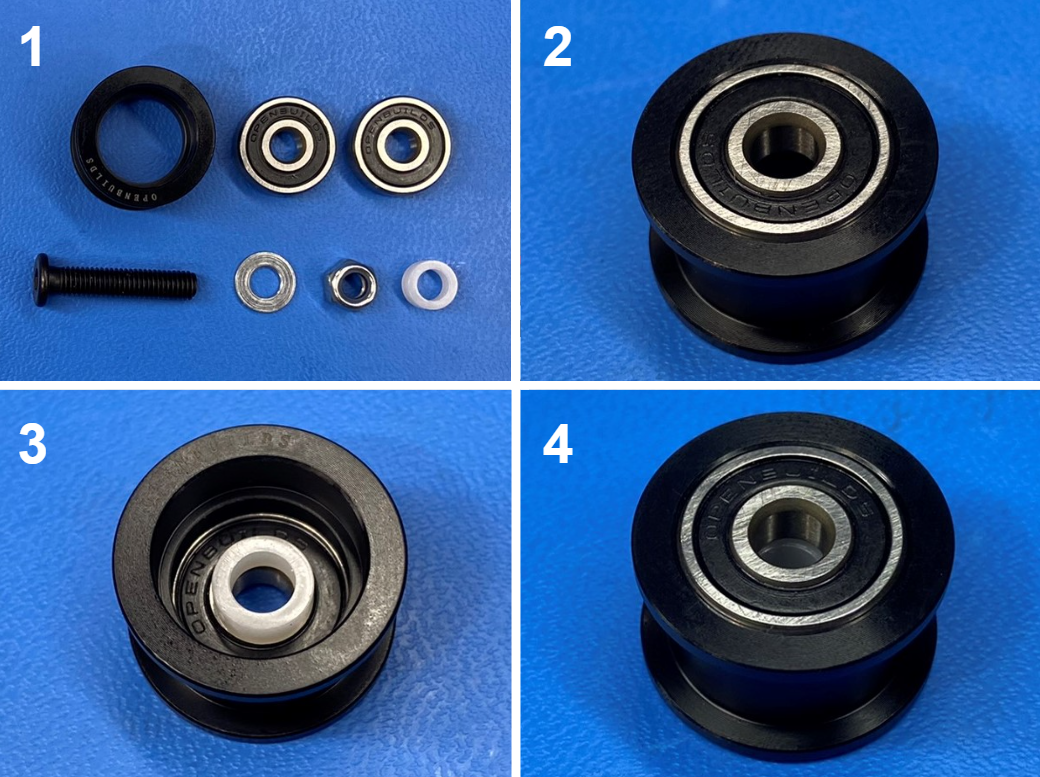
Open the smooth idler pulley wheel kit [HD-MS0412] and place 1x bearing inside the idler.
Then flip the idler over and place a spacer over the bearing making sure the holes align then place a bearing inside the idler sandwiching the spacer between the two bearings.
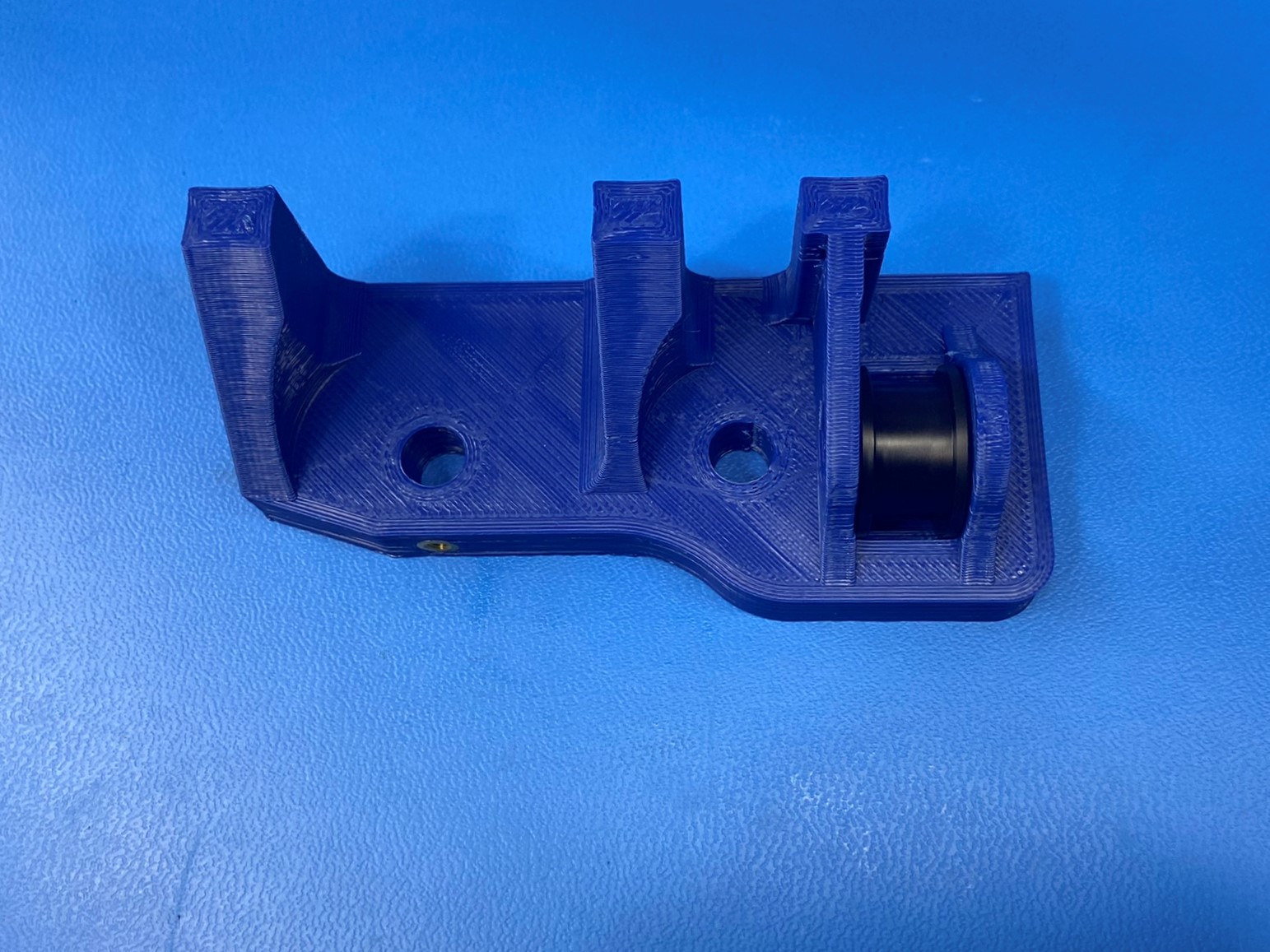
Now place the idler inside the idler slot on the Z upper right, take the screw and slide the washer over it. Then align the screw with the holes on the bearings and slide the screw through.
Thread the screw into the locknut to secure the idler inside the Z upper right. Make sure not to over tighten, the idler should be able to freely spin.

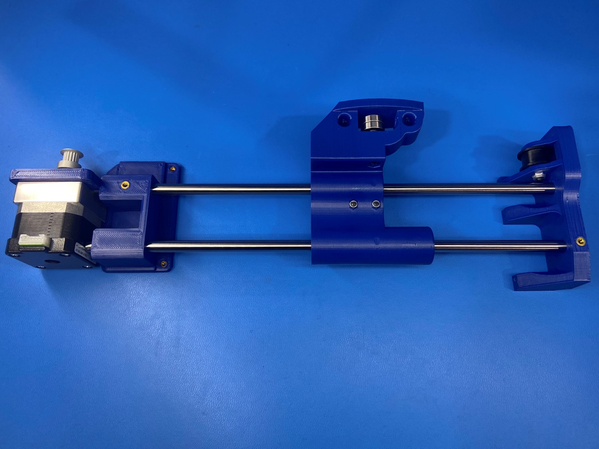
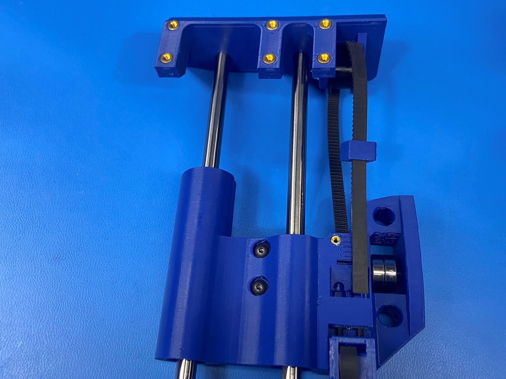
Install two hardened steel rods [HD-RD0035] into the Z lower right [PP-GP0313] Leave a 2-3mm gap between the bottom of the hardened steel rods and the motor.
Slide the X end idler assembly [PP-GP0131] onto the steel rods making sure the flat side is closest to the Z lower and make sure that the idler is on the same side as the motor pulley.
Ream the steel rod holes on the Z upper right [PP-GP0312] with the 8mm part reamer
Slide the Z upper right to the end of the hardened steel rods opposite the Z lower right assembly as pictured.
Install two M3x6 set screws [HD-BT0012], install one to the insert on the Z lower right near the steel rod, install the second one in the Z upper right near the steel rod. Do not tighten
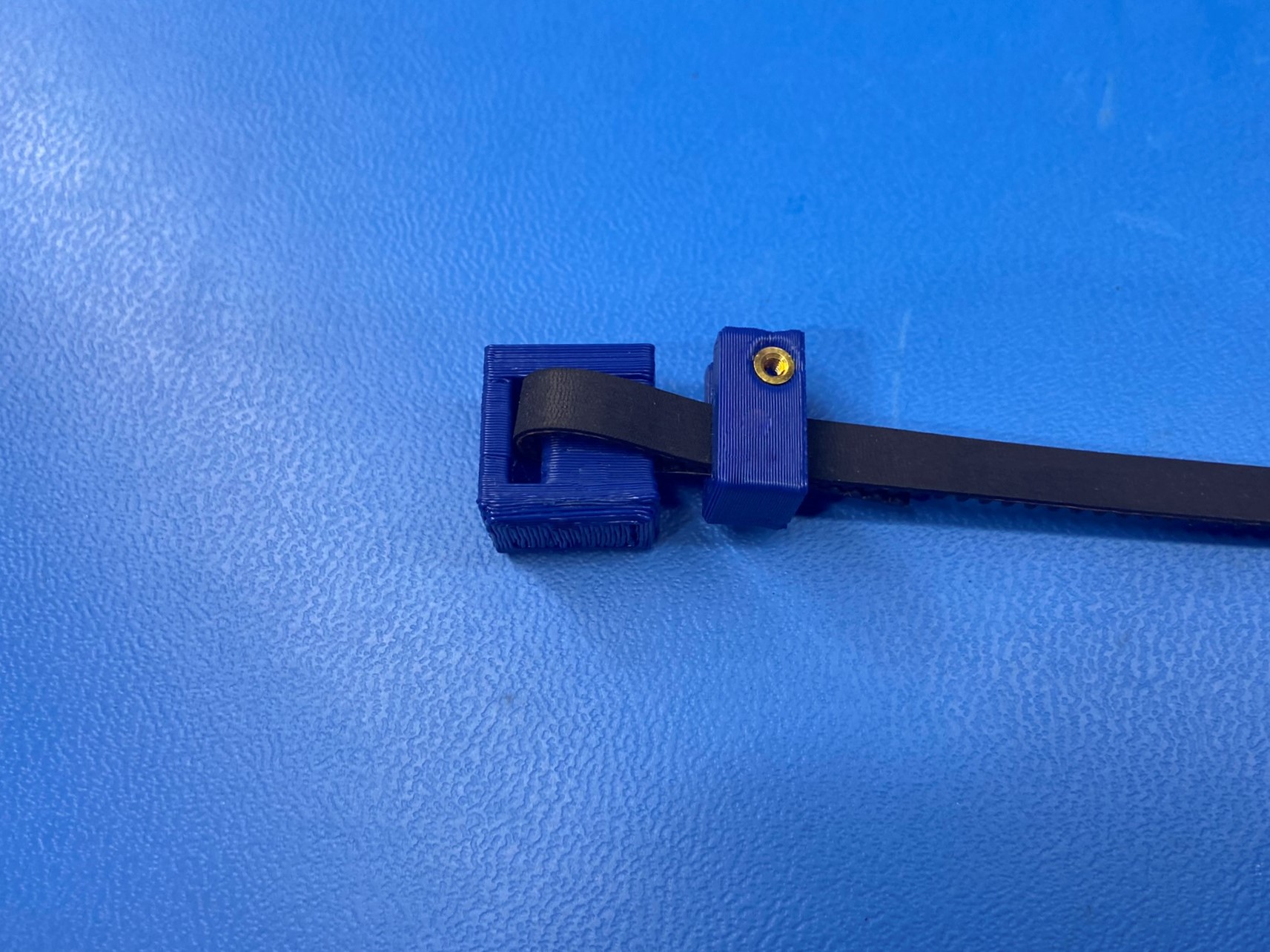
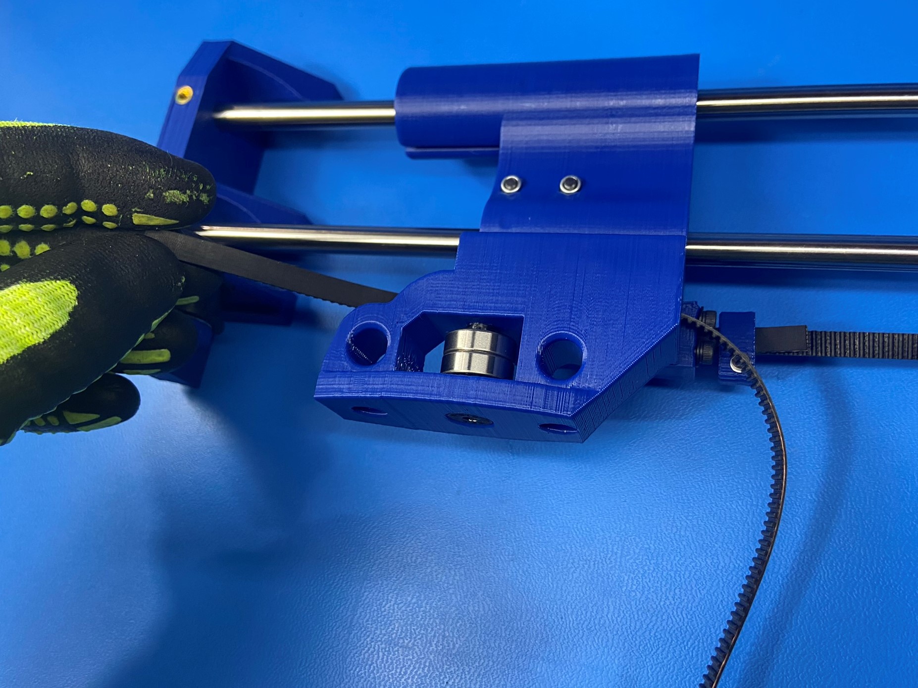
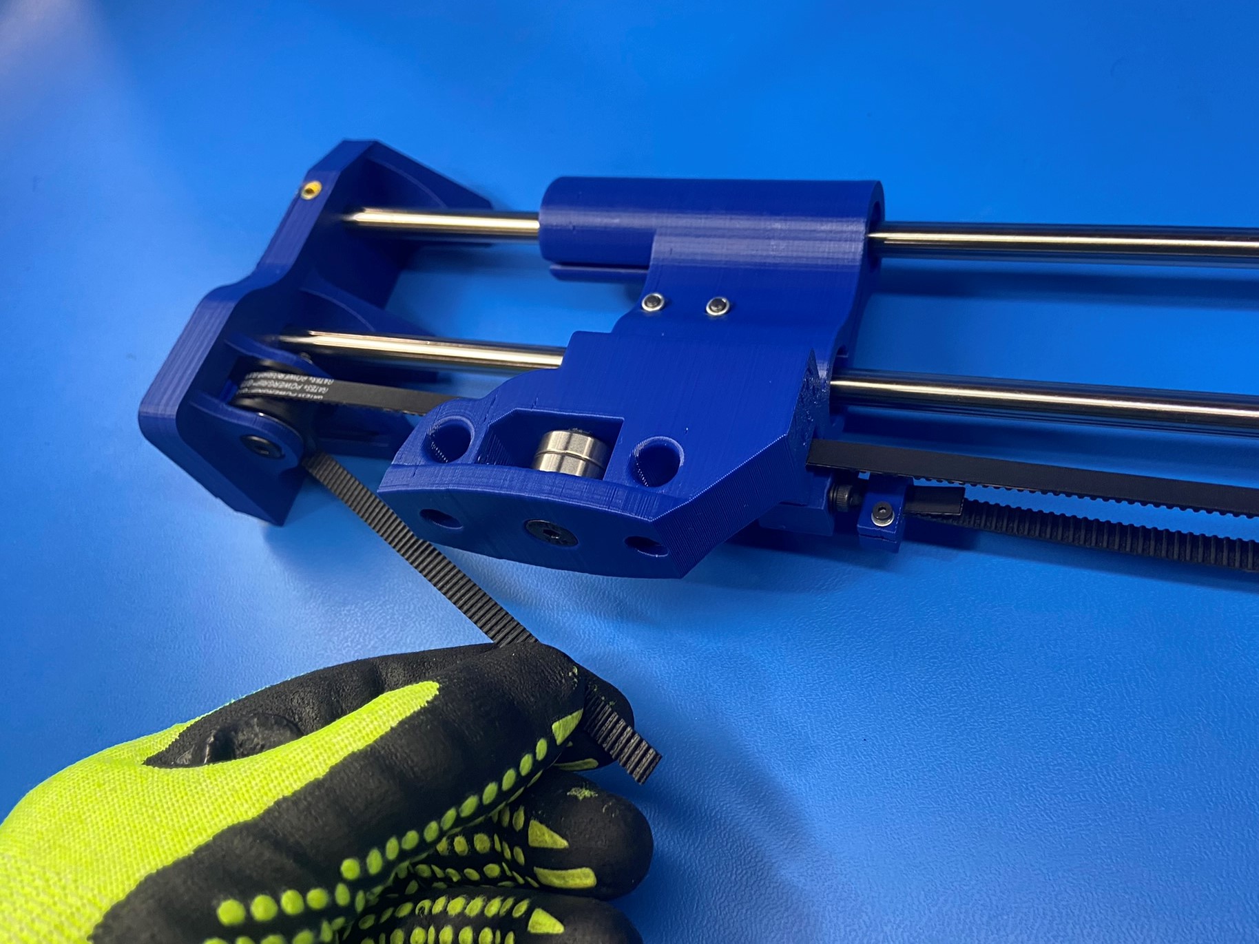
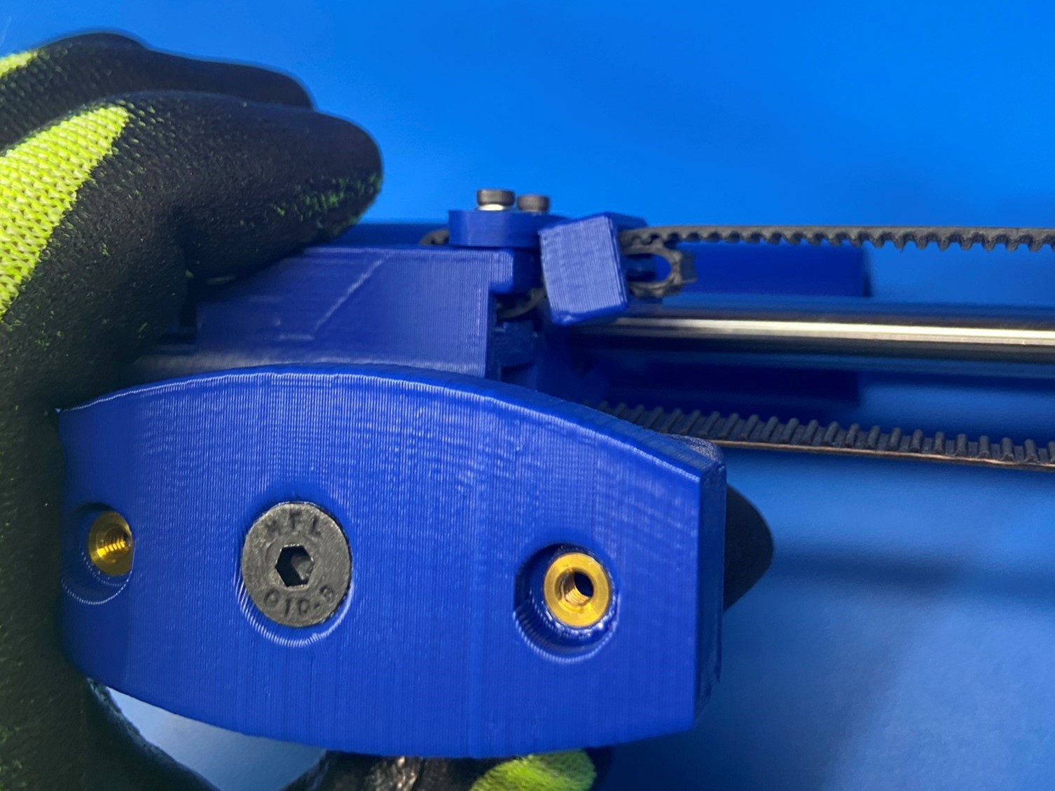
Cut a belt [HD-BL0033] straight with the the teeth of the belt and insert one end into the bottom slot of the belt tensioner block [PP-GP0645] then continue pushing the belt until the end come out of the front slot.
Once the belt is routed through the bottom and front slot on belt tensioner block, pinch the two side of the belt together and slide the U channel belt clamp [PP-GP0680] over the belt. Make sure to leave a little less than half an inch of belt coming out of the bottom slot. The side without the insert will be on the same side as the two holes on the belt tensioner block.
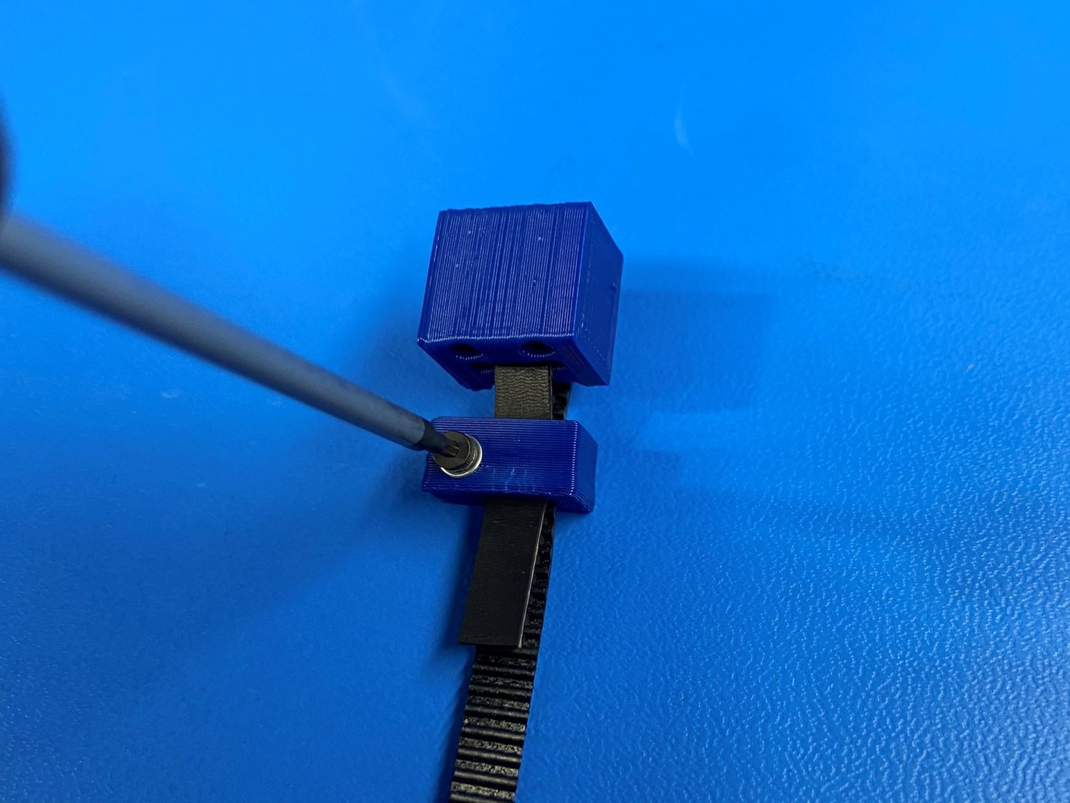
Use 1x M2x10 SHCS [HD-BT0107] and 1x M2 washer [HD-WA0012] and tighten the clamp around the belt, thread the screw through the hole without an insert first.
Place 2x M3 locknuts [HD-NT0001] in the two hex holes on the X end idler assembly.
Then using 2x SHCS M3x30 [HD-BT0042] with 2x M3 washers [HD-WA0038] attach the belt tensioning block to the X end idler assembly. Note: Stop once the bolts are fully through the locknuts


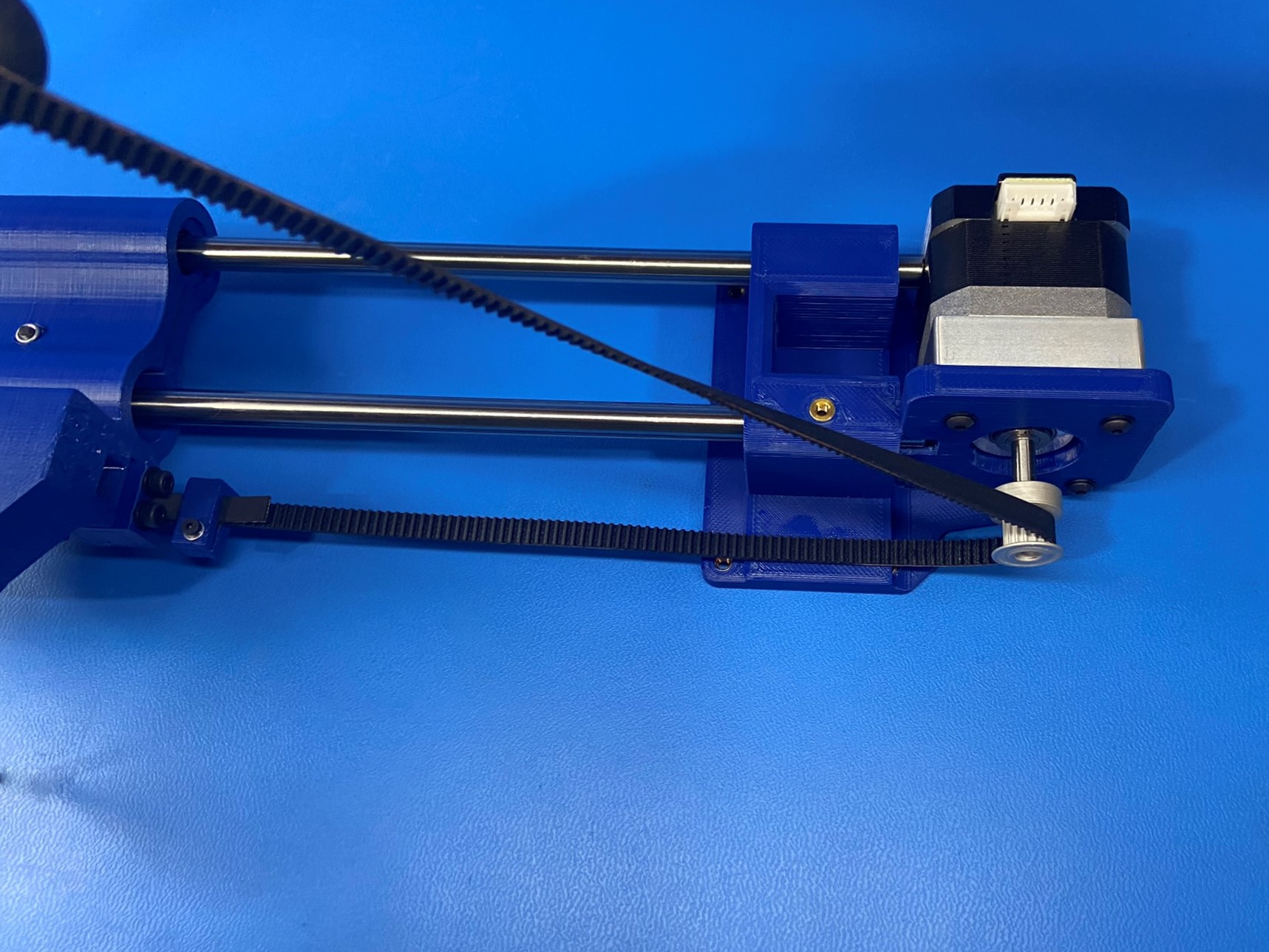
Take the end of the belt and wrap it around the timer pulley that's attached to the motor, then slide the belt through the channel on the X end idler assembly.
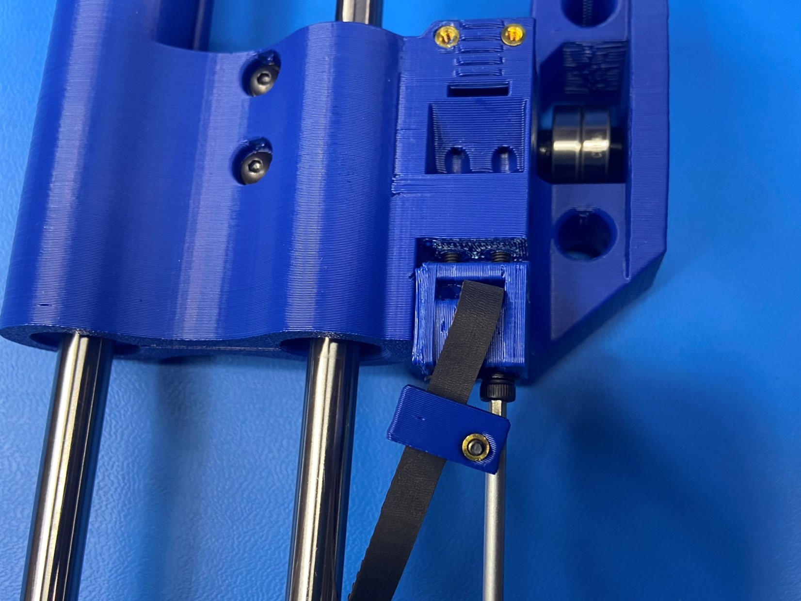
Now route the belt around the Z upper idler, then take 1x belt tensioning collar [PP-GP0511] and slide it over the belt. Make sure the belt goes through the bigger slot on the tensioning collar.
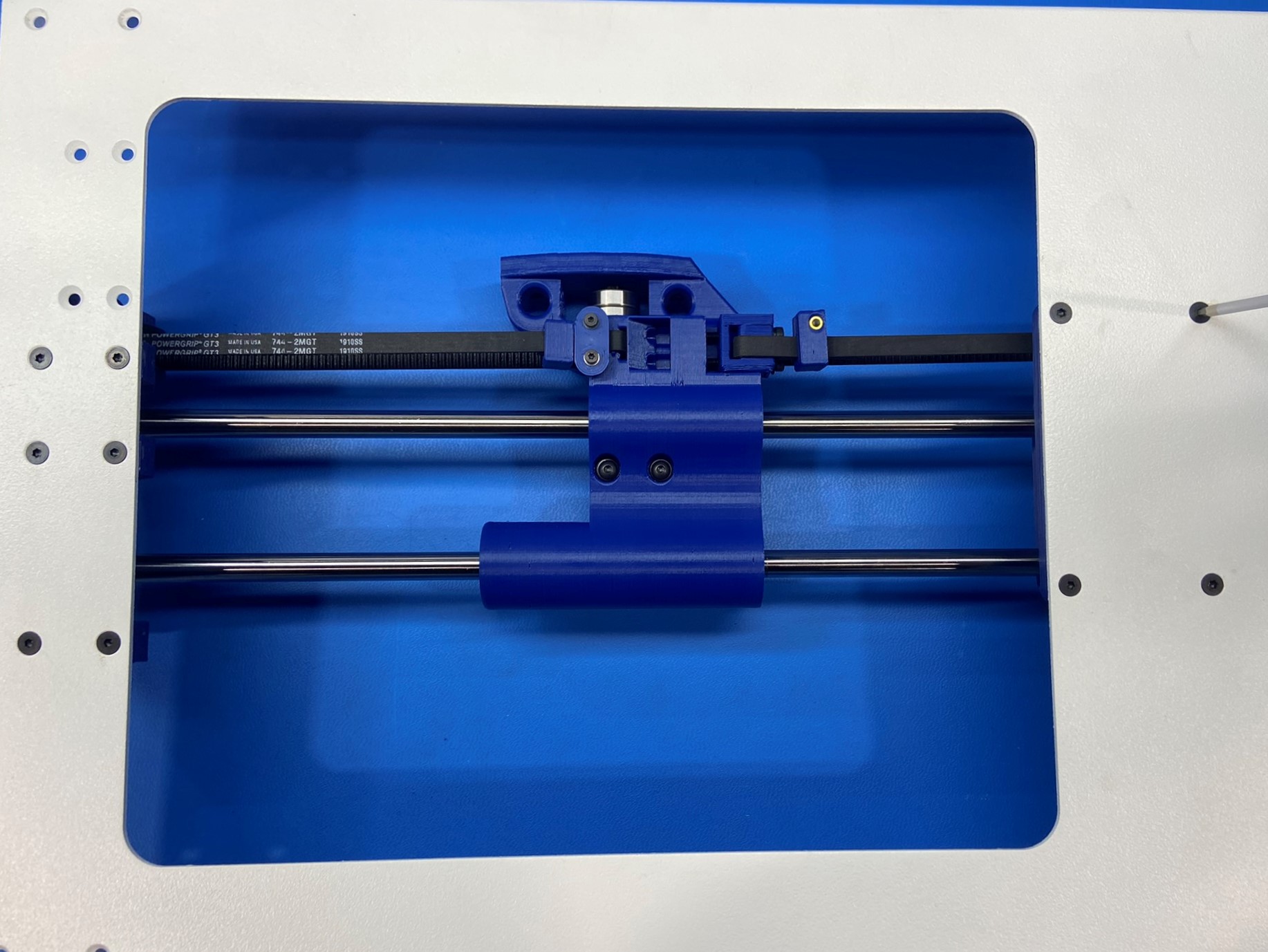
Then push the belt through the slot on the front side of the X end idler until the belt come through the slot on the top side.
Then pull the belt tight and secure the Z belt clamp [PP-GP0512] to the X end idler using 2x M2x10 SHCS [HD-BT0107] with M2 washers [HD-WA0012].
Then pinch the belt together and slide the belt tensioning collar over both sides of the belt and fold the tail end into the smaller slot on the collar.

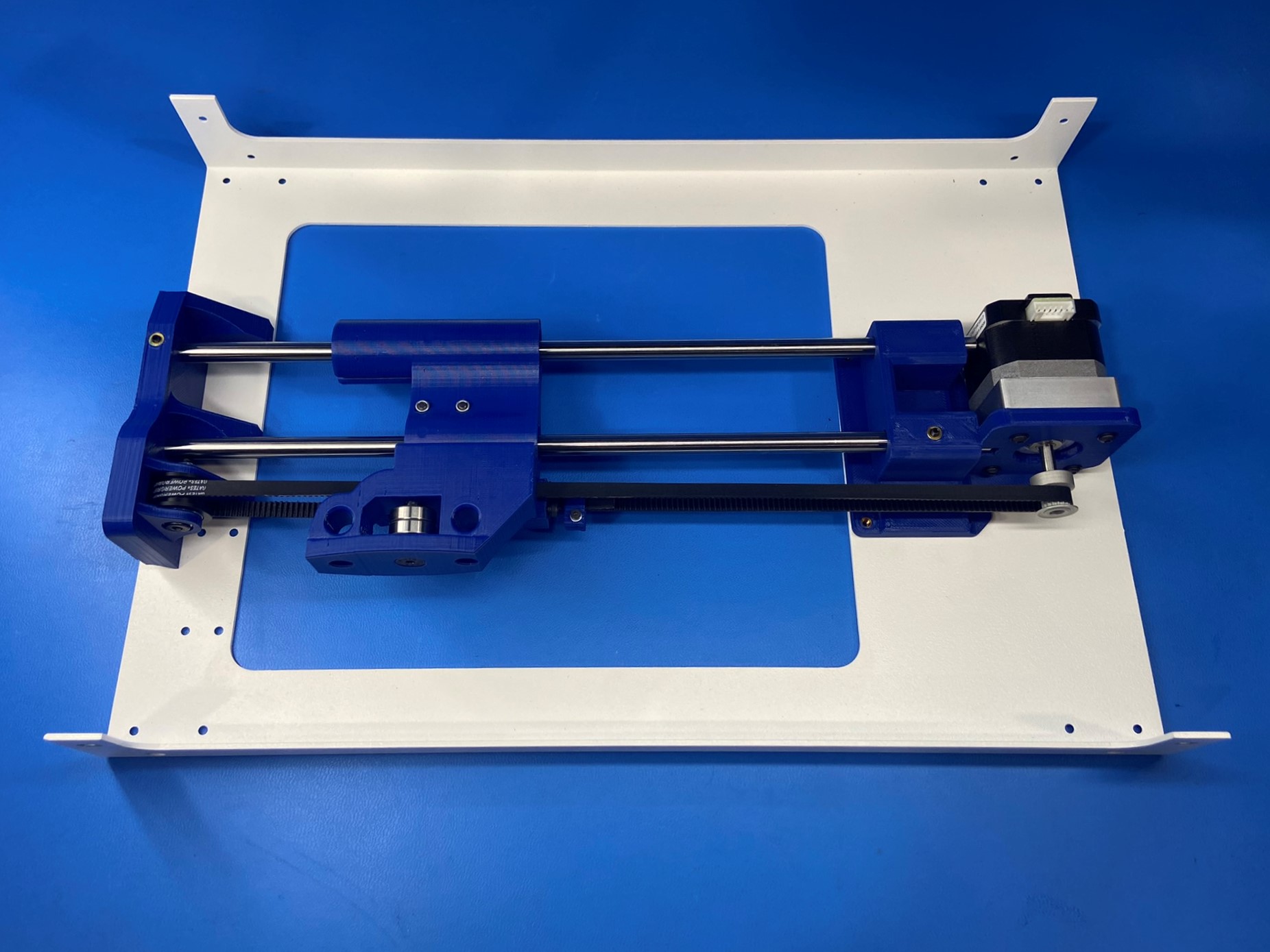
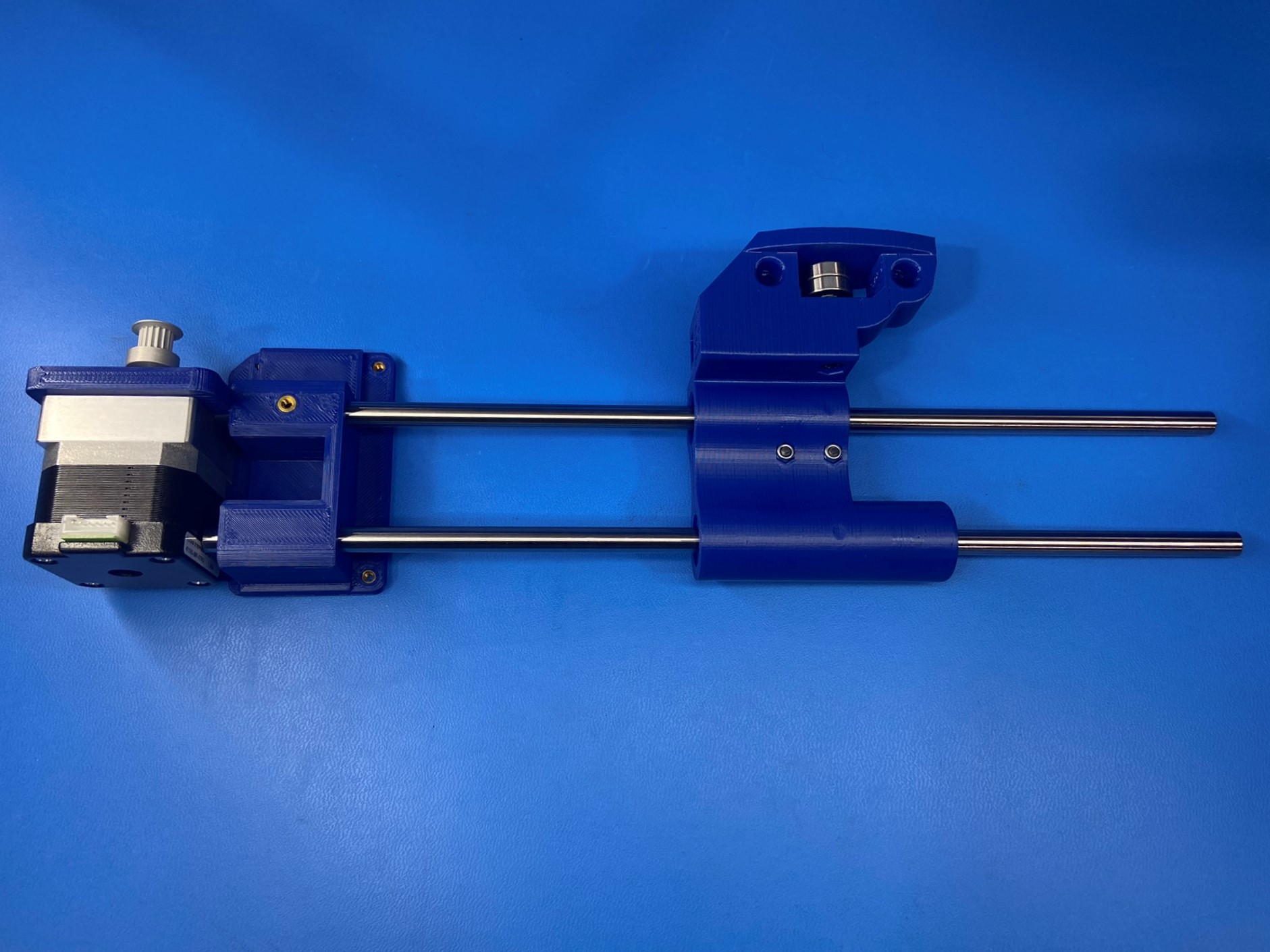
Align the Z axis right assembly with the Mini right side - white [PP-FP0169].
Using 4x M3x6 FHCS [HD-BT0128] secure the Z lower right to the Mini right side.
Using 6x M3x6 FHCS secure the Z upper right to the Mini right side.
Ensure the steel rods are not making contact with the Z motor, this can cause unwanted noise/vibration, there should be a 2-3mm gap between the motor housing and the bottom of the smooth rods.
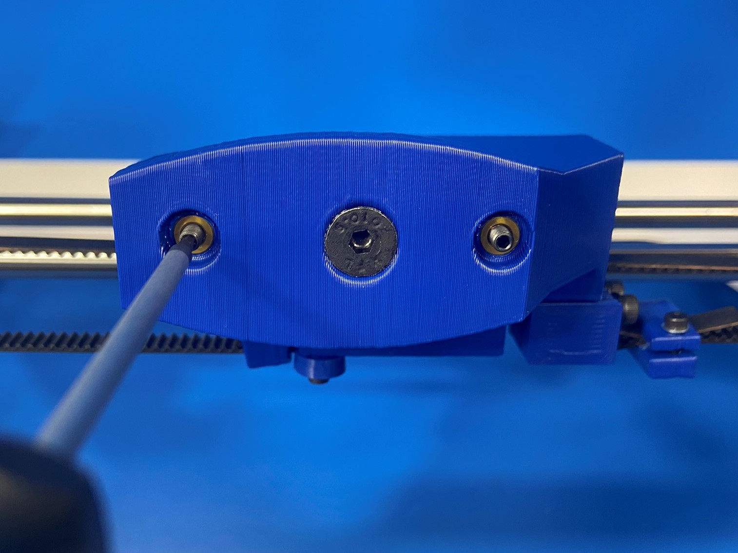
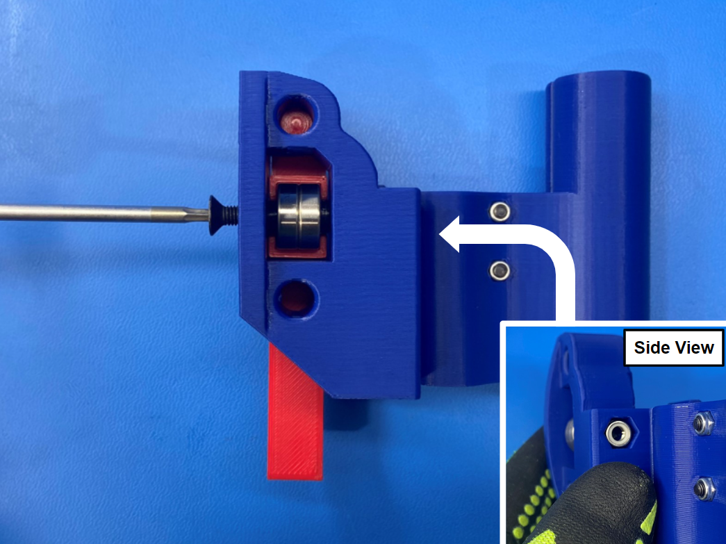
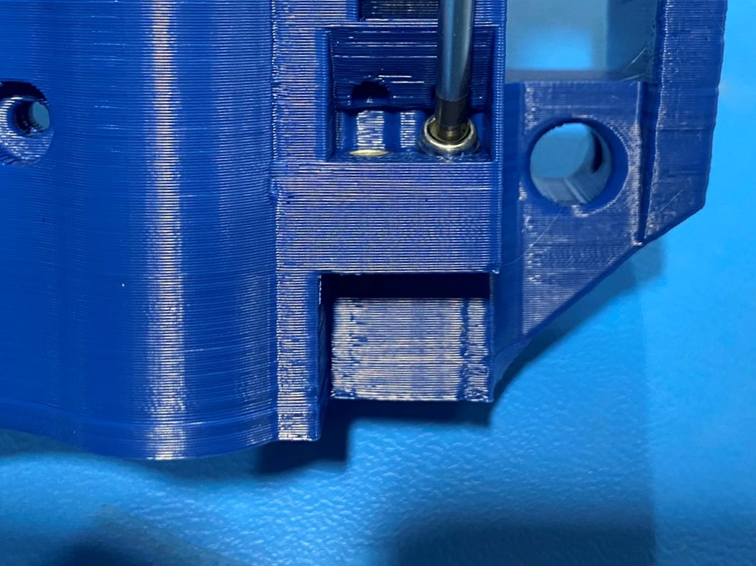
Torque both smooth rod set screw on the Z-Lower to 3in*lbs as pictured
Once the assembly is attached to the Mini right side install 2x M3x6 set screws [HD-BT0012] to the X end idler.