Open HardwareAssembly Instructions
Guides for installation and assembly of the LulzBot line of products made by FAME 3D LLC.
Guides for installation and assembly of the LulzBot line of products made by FAME 3D LLC.
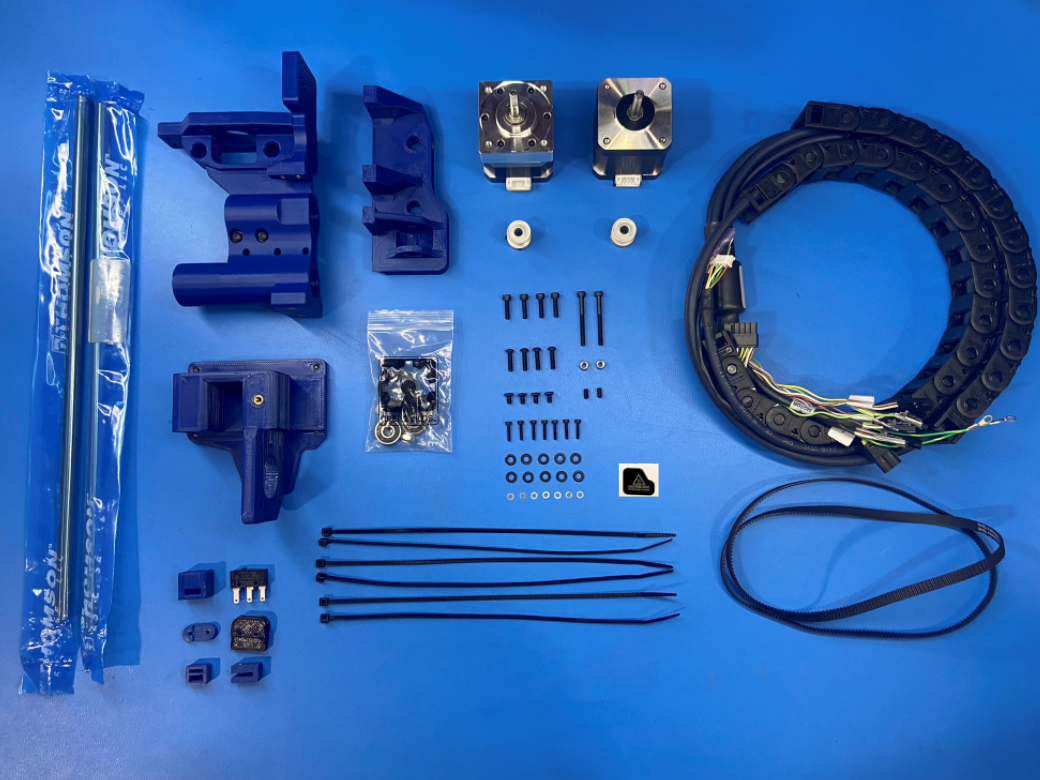
1x- [DC-LB0154] Caution Hot Sticker
1x- [EL-HR0130] X Extruder Harness
1x- [EL-MT0056] Moons Motor, Gear Ratio 5:1
1x- [EL-MT0068] NEMA 17 Stepper Motor
1x- [EL-SW0022] Switch Basic 3A 125V
1x- [HD-BL0033] Single Sided Neoprene Belt, 744mm
2x- [HD-BT0012] M3x6 Set Screw, Black-Oxide
4x- [HD-BT0039] M3x12 SHCS, Black-Oxide
2x- [HD-BT0042] M3x30 SHCS, Black-Oxide
7x- [HD-BT0107] M2x10 SHCS, Black-Oxide
4x- [HD-BT0128] M3x6 FHCS, Black-Oxide
4x- [HD-BT0146] M3x12 BHCS, Black-Oxide
2x- [HD-MS0033] 16 Teeth, Timing Pulley
6x- [HD-MS0058] Wire Tie 8"
1x- [HD-MS0412] Smooth Idler Pulley Wheel Kit
2x- [HD-NT0001] M3 Locknut
2x- [HD-RD0078] Hardened Steel Linear Rod 315mm
7x- [HD-WA0012] M2 Washer, Zinc
10x- [HD-WA0038] M3 Washer, Black-Oxide
1x- [PP-GP0130] X End Motor
1x- [PP-GP0309] Z Upper Left
1x- [PP-GP0310] Z Lower Left
1x- [PP-GP0332] Bump Stop
1x- [PP-GP0511] Belt Tensioning Collar
1x- [PP-GP0512] Z Belt Clamp
1x- [PP-GP0645] Belt Tensioner Block
1x- [PP-GP0680] U Channel Belt Clamp
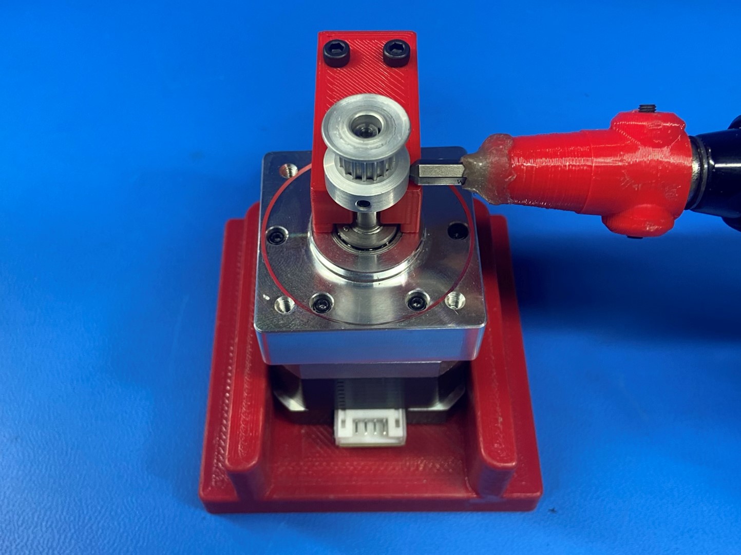
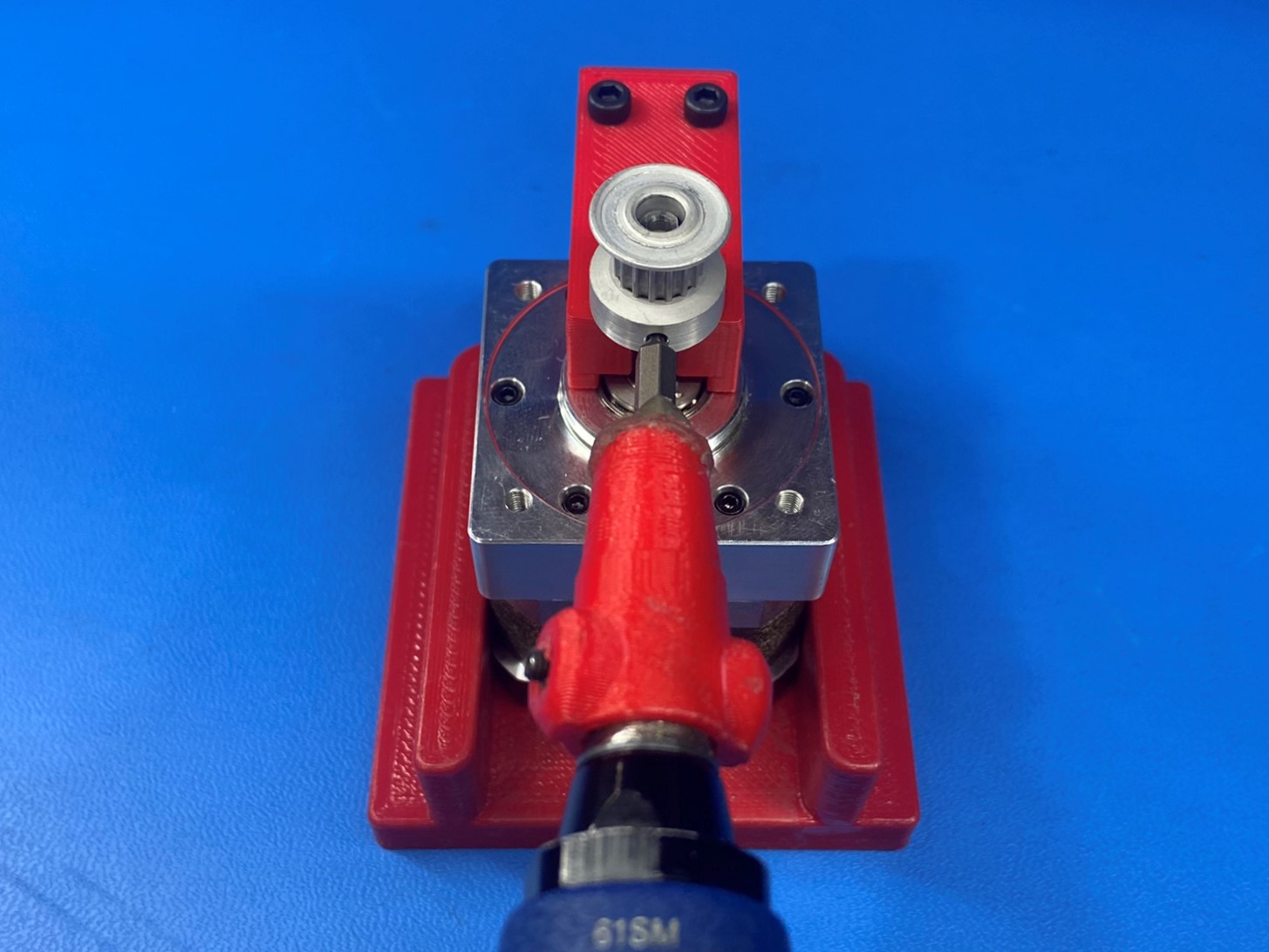
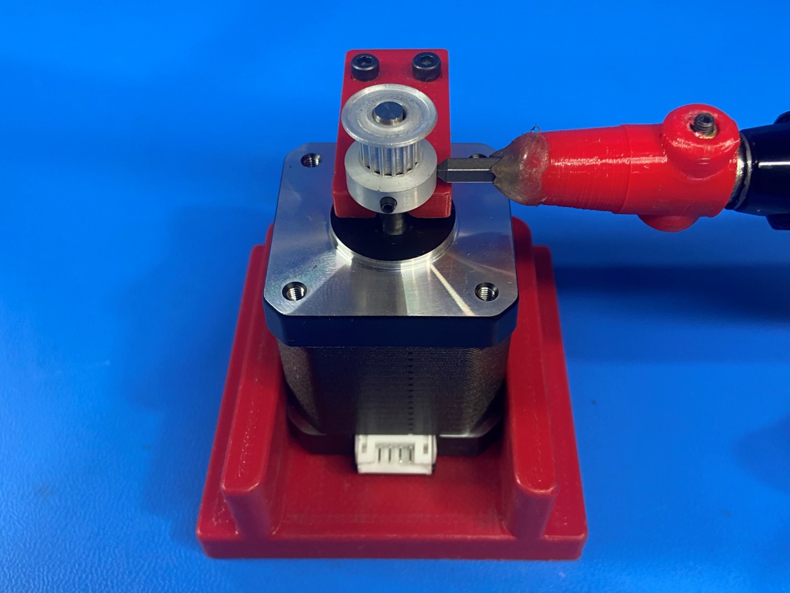
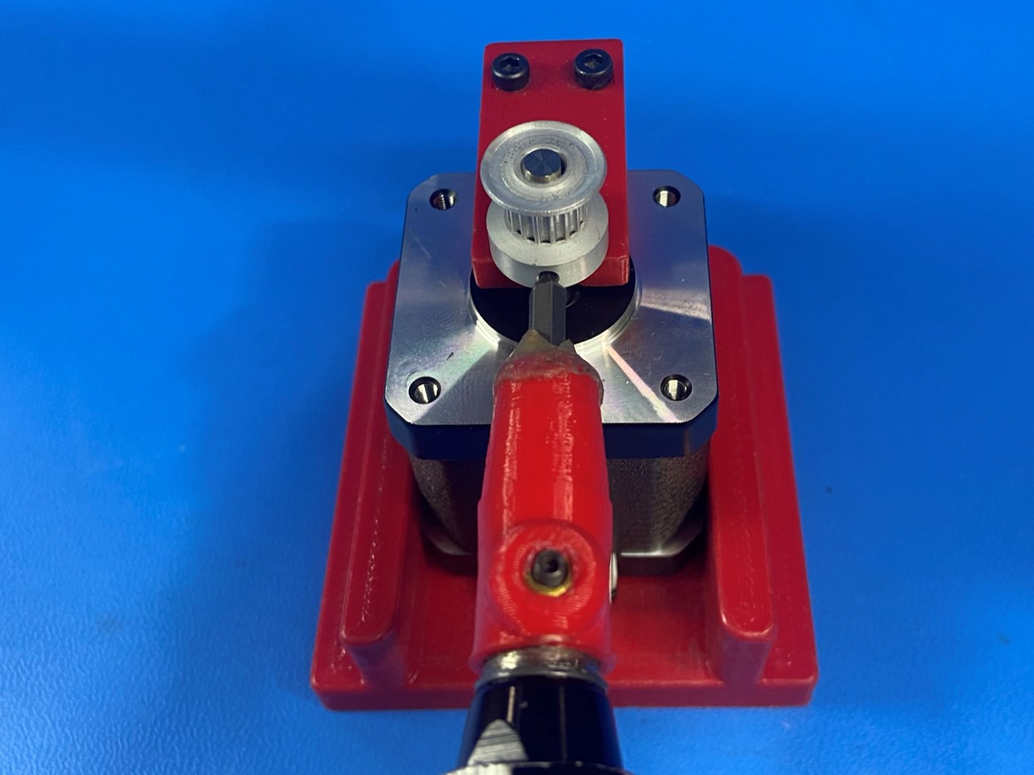
Attach a pulley [HD-MS0033] to the Moons motor 5:1 [EL-MT0056]using the Bio motor jig. Ensure one of the pulley set screws is aligned with the flat segment of the motor shaft, secure pulley in place with the two set screws already installed in the pulley, tighten to 3 in*lbs.
Align the Z motor with the Z lower left (orientation is critical) the motor connector should be facing toward the right of the Z lower left part.
Attach the motor to the Z lower left using 4x M3x12 BHCS [HD-BT0146] with 4x M3 washers [HD-WA0038].

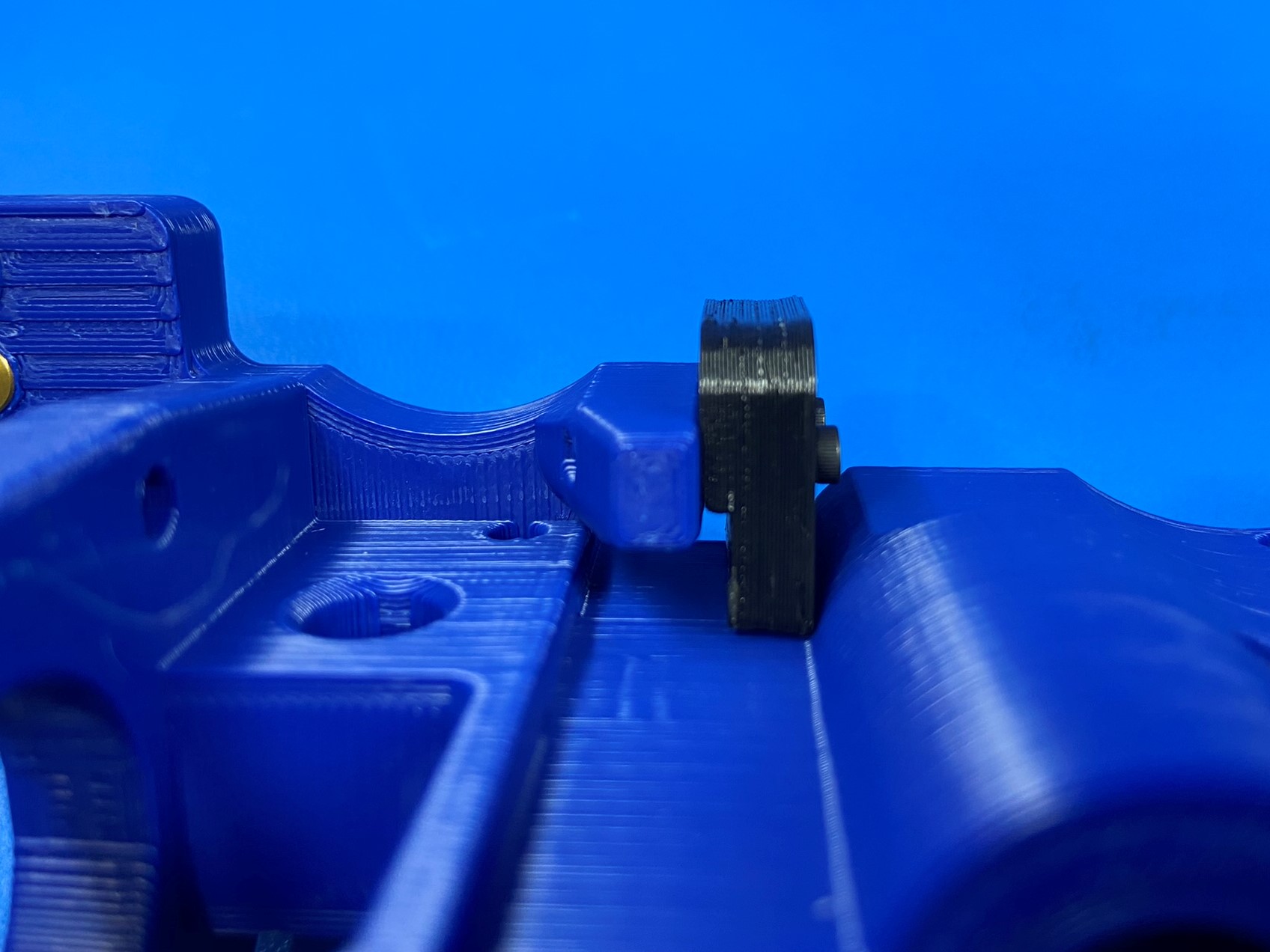
Align and install the Bump Stop [PP-GP0332] with the mount located in the middle of the X end motor assembly [PP-GP0130] as pictured. The bump stop should be oriented with the flat side facing away from the belt path.
Secure the bump stop with 2x- M2x10 SHCS [HD-BT0107] with M2 washers [HD-WA0012], tighten screws until the bump stop no longer moves freely.
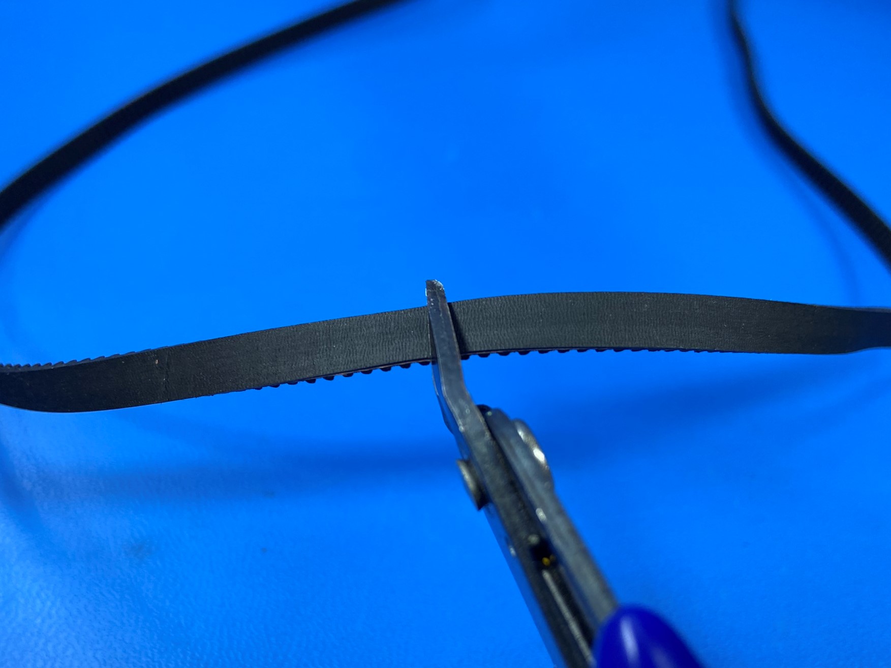
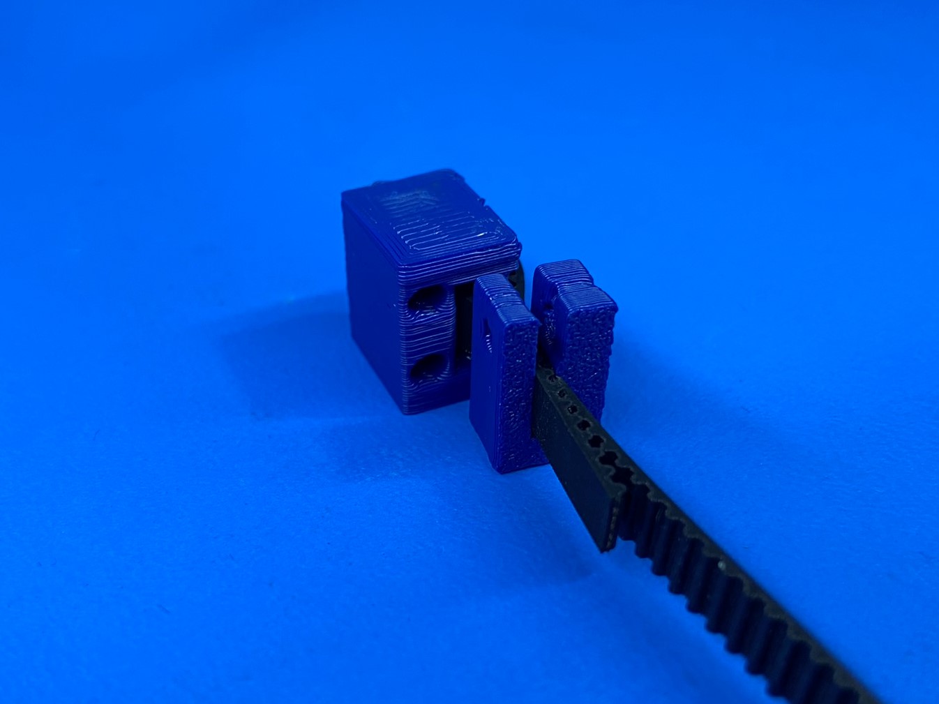
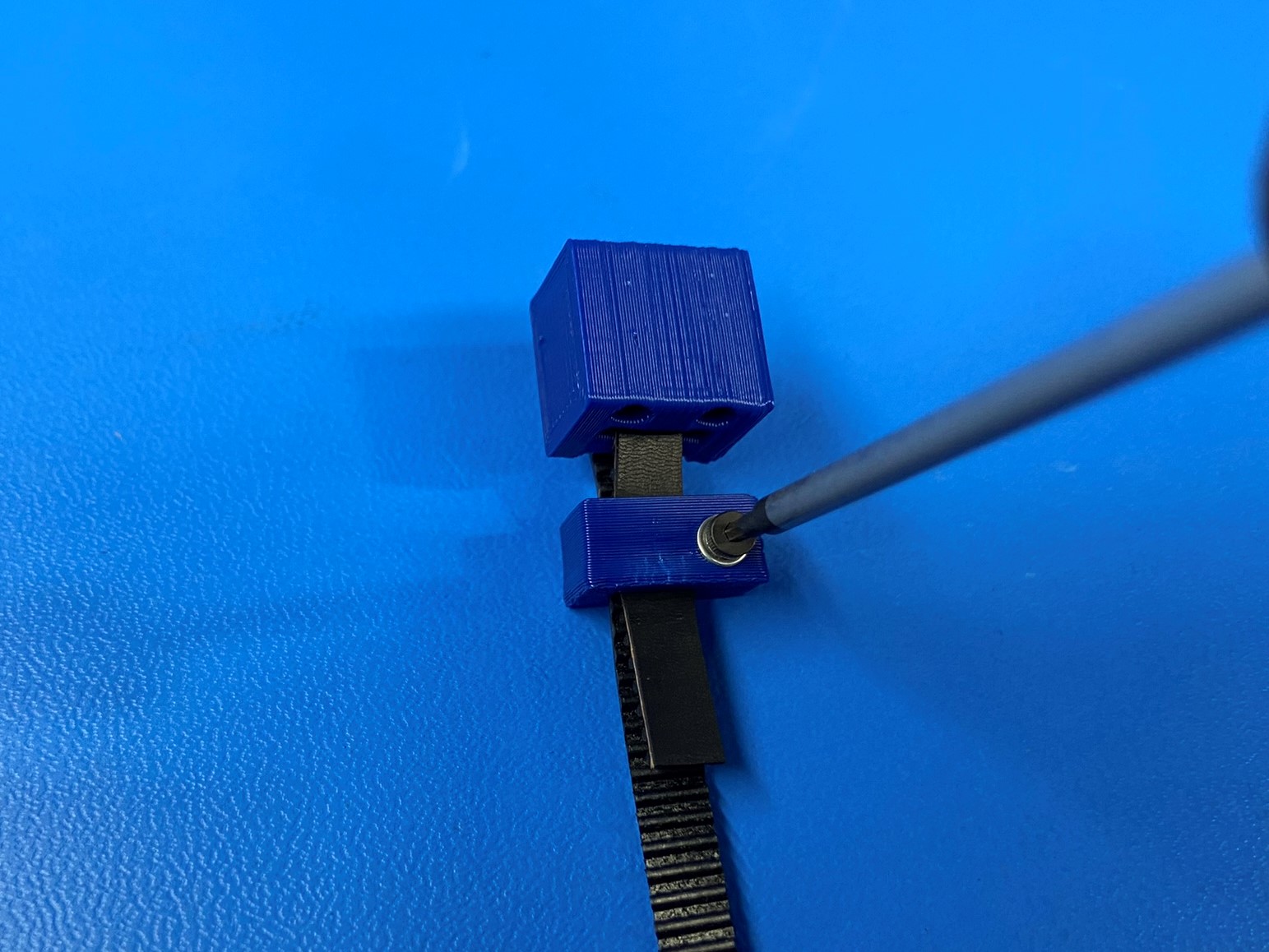
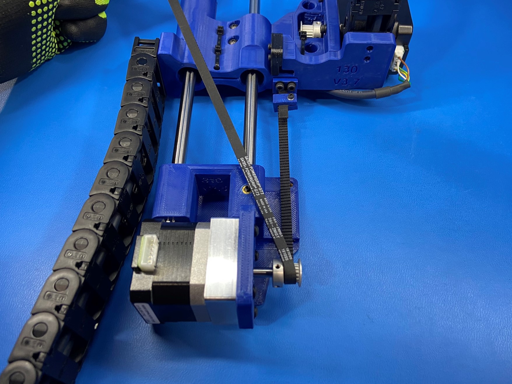
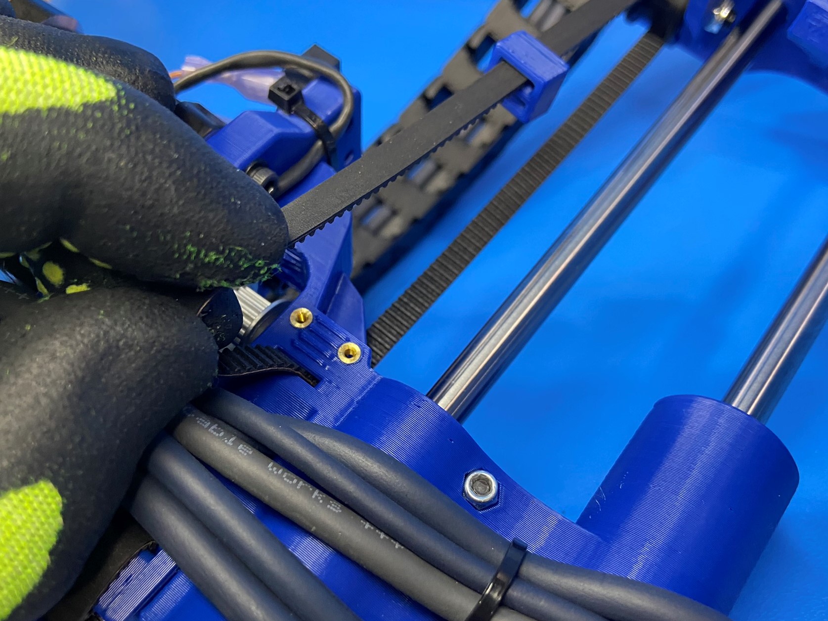
Cut a belt [HD-BL0033] straight with the the teeth of the belt and insert one end into the bottom slot of the belt tensioner block [PP-GP0645], [reference#1] then continue pushing the belt until the end come out of the front slot.
Once the belt is routed through the bottom and front slot on belt tensioner block, pinch the two side of the belt together and slide the U channel belt clamp [PP-GP0680] over the belt. Make sure to leave a little less than half an inch of belt coming out of the bottom slot. The side without the insert will be on the same side as the two holes on the belt tensioner block.
Use 1x M2x10 SHCS [HD-BT0107] and 1x M2 washer [HD-WA0012] and tighten the clamp around the belt, thread the screw through the hole without an insert first.
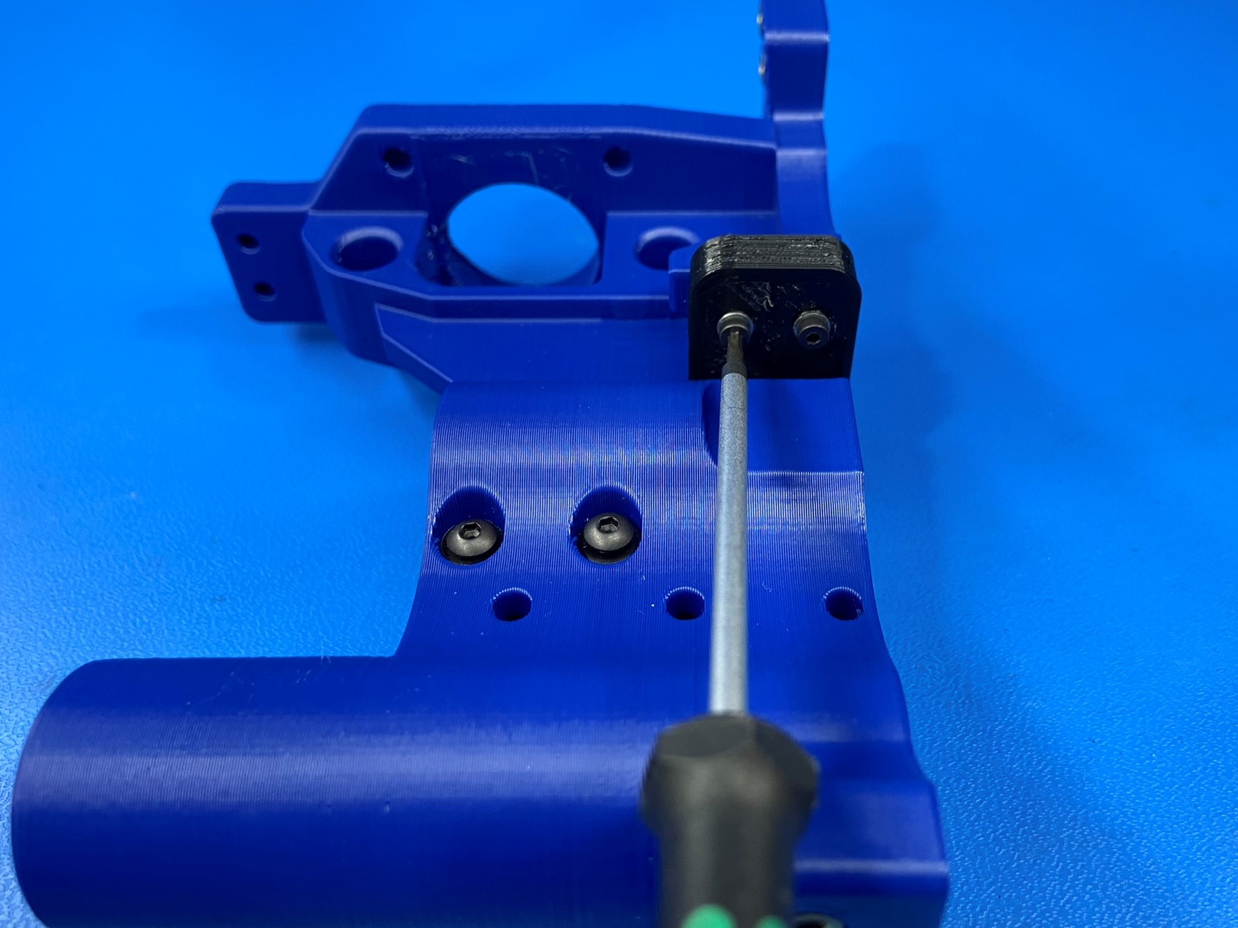
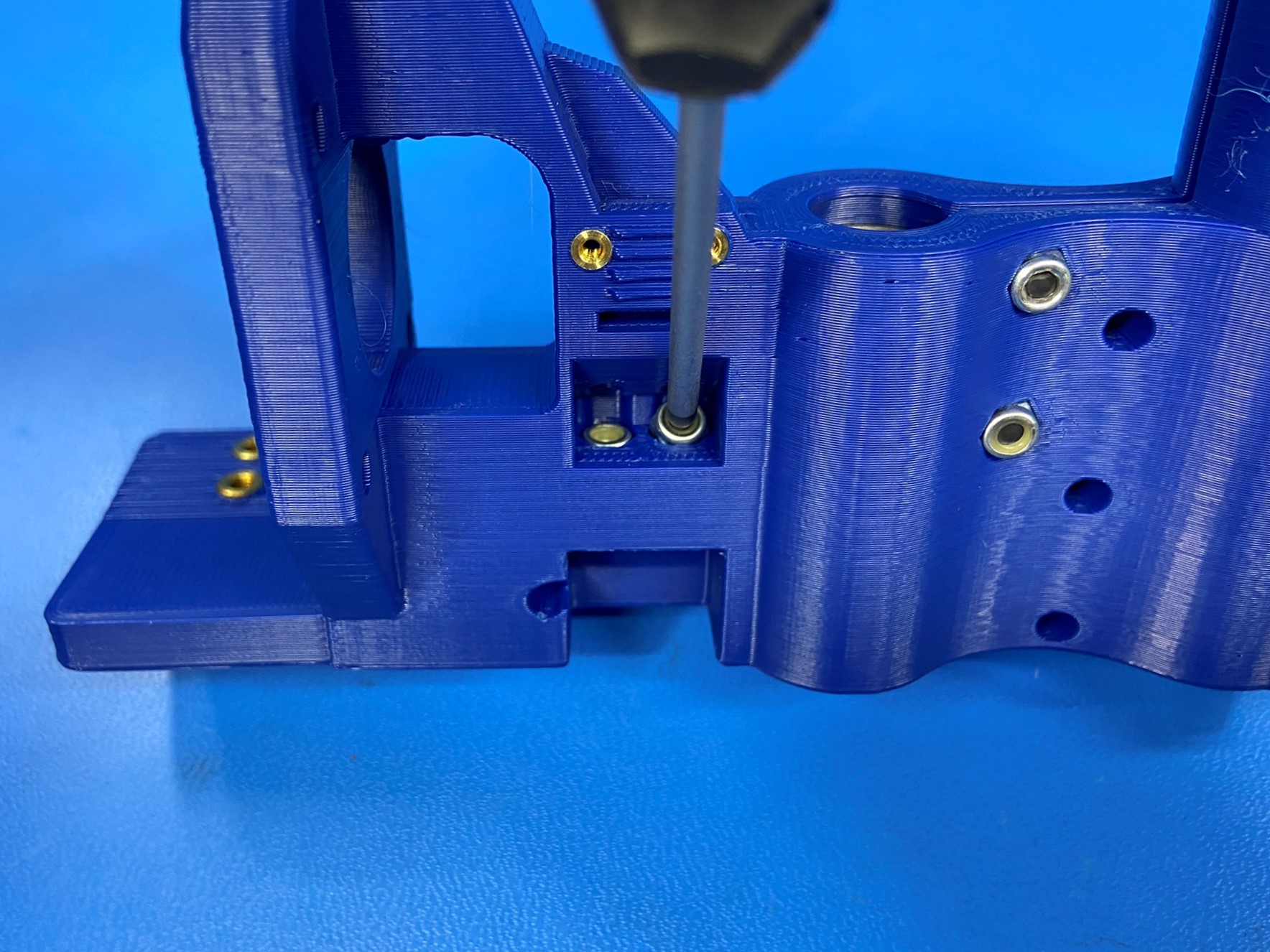
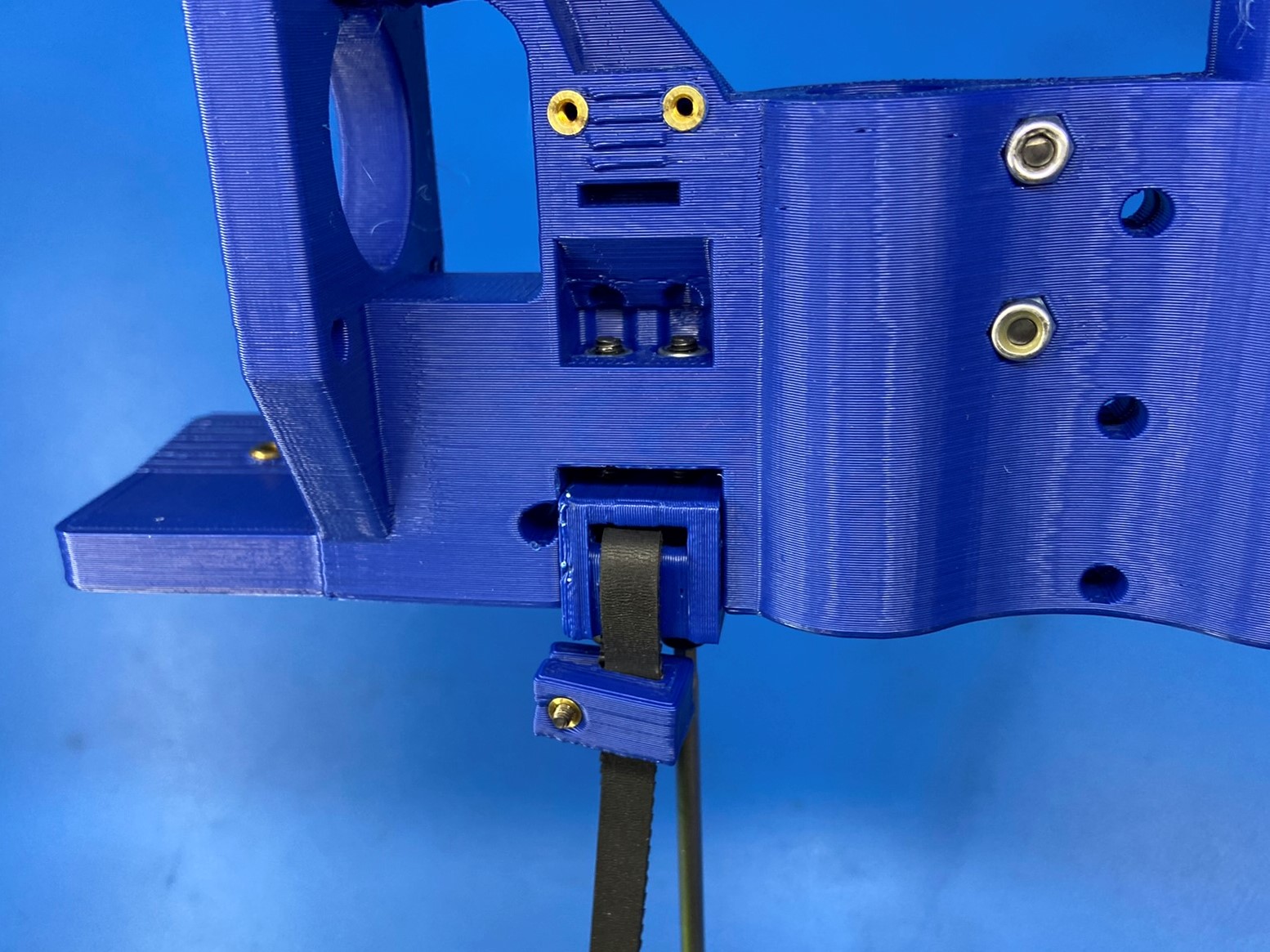
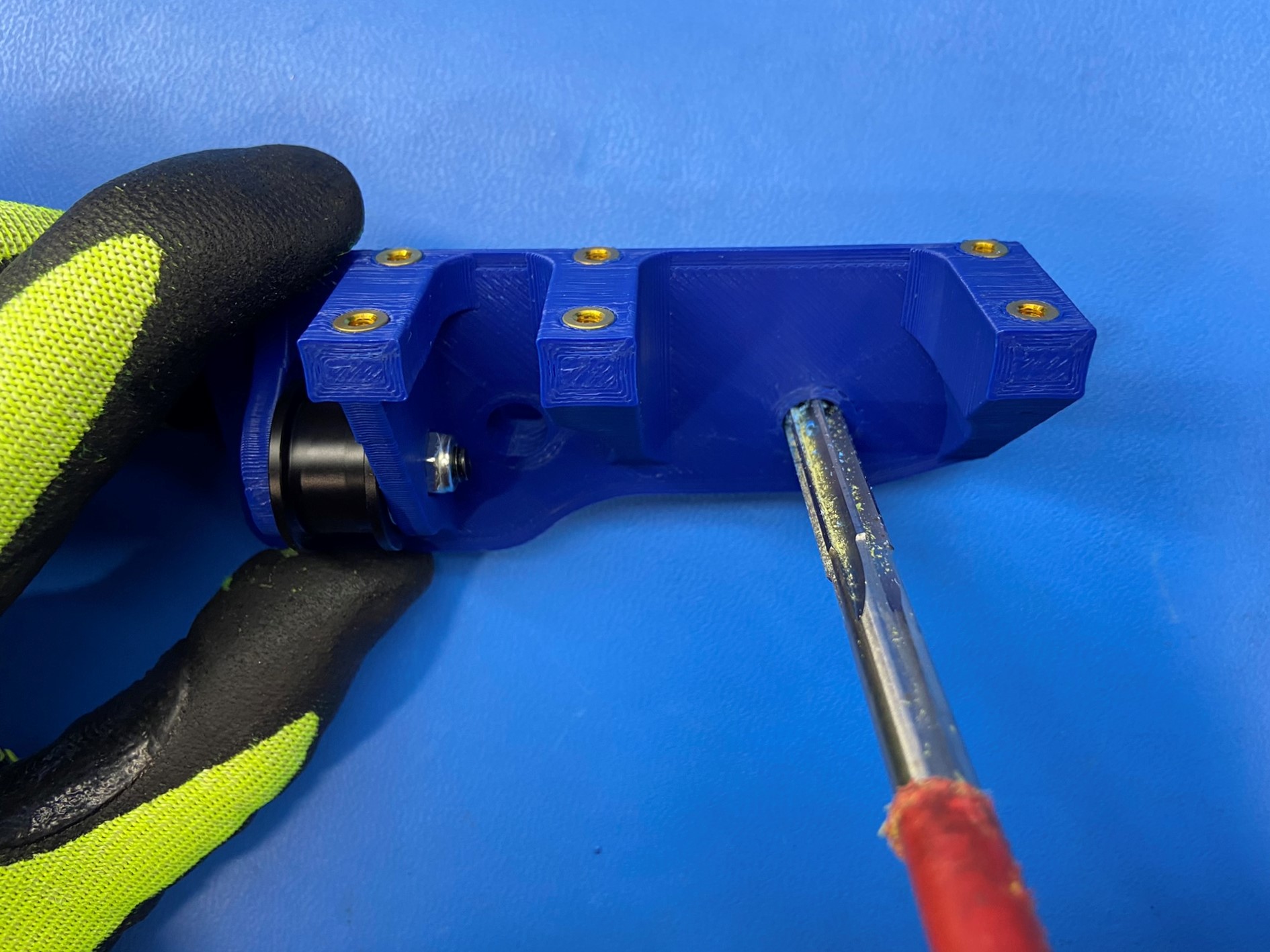
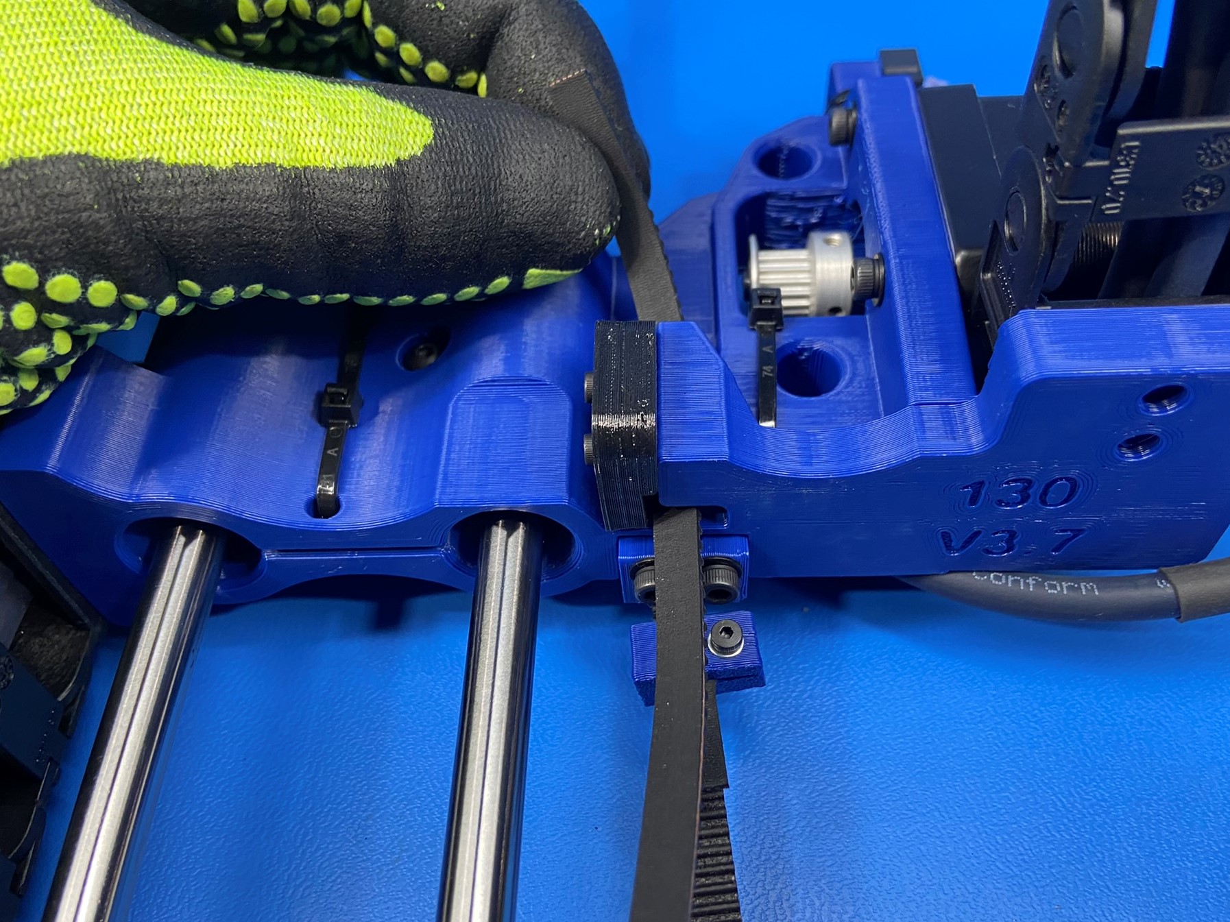
Place 2x M3 locknuts [HD-NT0001] in the two hex holes on the X end motor assembly
Then using 2x SHCS M3x30 [HD-BT0042] with 2x M3 washers [HD-WA0038] attach the belt tensioning block to the X end motor assembly. [reference#2] Note: Stop once the bolts are fully through the locknuts

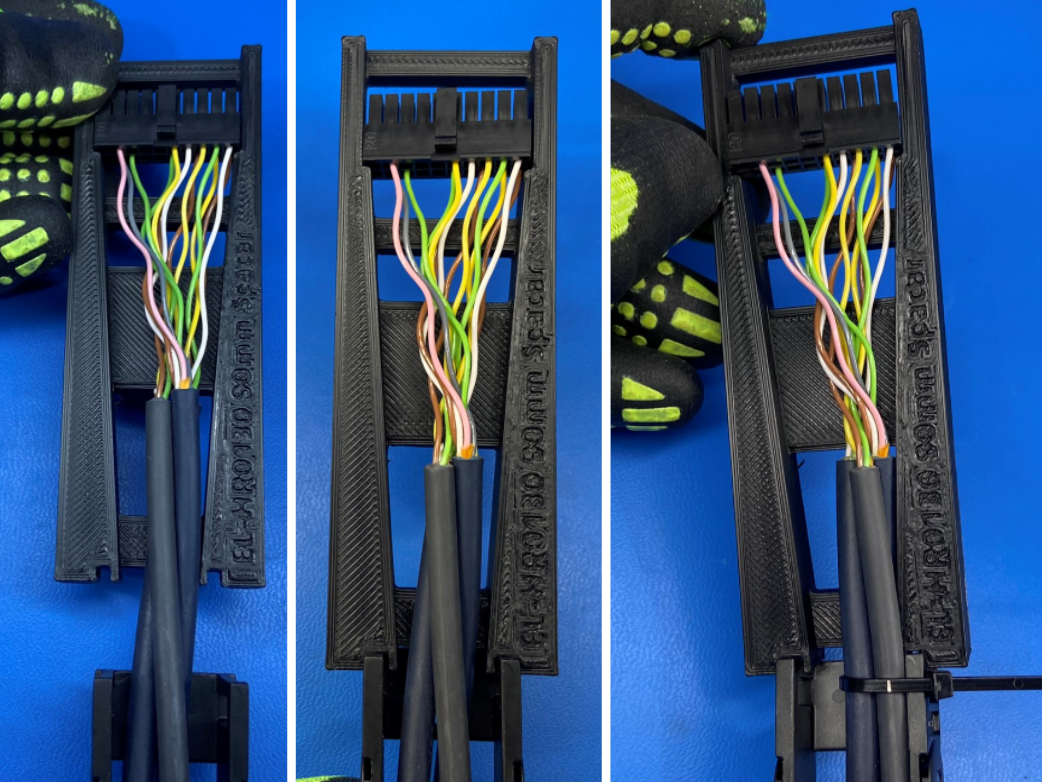
Using the wire length jig, adjust the length of wire on the 3 wire segment of the X extruder harness [EL-HR0130]. Make sure the wire connector is placed in the wide end of the jig and that the cable chain is pushing against the two slots on the bottom side of the jig, then secure wires with 1x cable tie [HD-MS0058]
Attach both cable chains on the X extruder harness to the X end motor assembly using 2x M3x6 FHCS [HD-BT0128] for each chain. The three wire segment on the motor side of the X end motor assembly and the five wire segment on the bushing side.
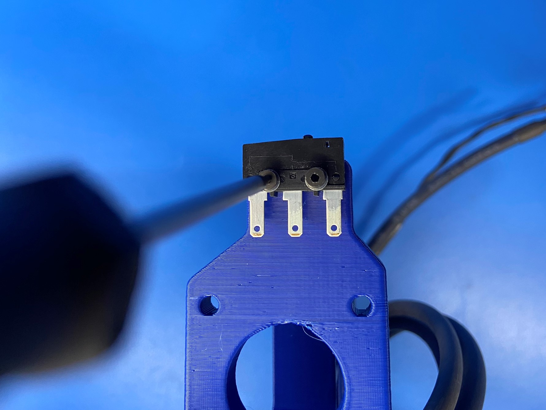
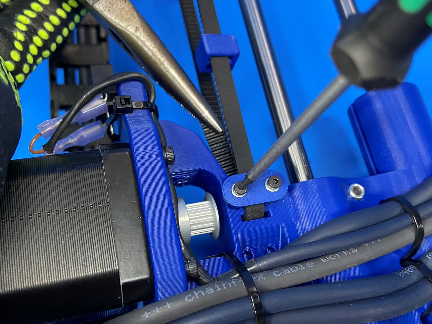
Next align and install the Z max end stop switch [EL-SW0022] with the switch mount located above the motor mount. Secure the switch with 2x M2x10 SHCS [HD-BT0107] and M2 washers [HD-WA0012], tighten screws to 3 in*lbs.
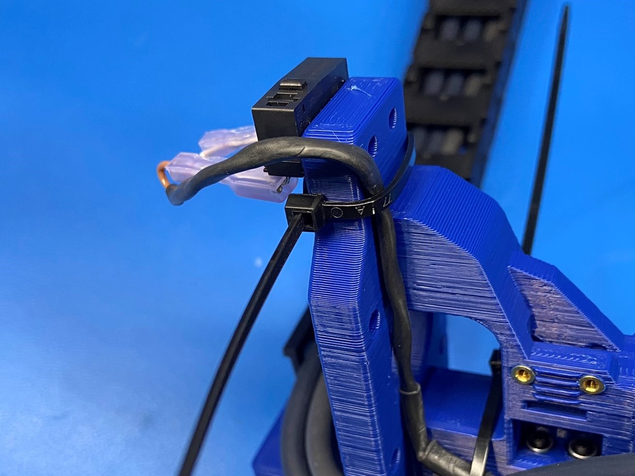
Follow the Cable Tie Placement Guild when installing the cable ties
Follow the RED Circle and Arrow
Using 1x cable tie [HD-MS0058] secure the two lower wires. The cable tie head must be by the RED arrow.
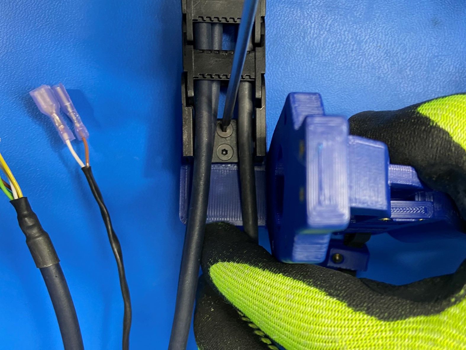
Then pass the X motor cable underneath the three extruder harness cables. [reference#3]
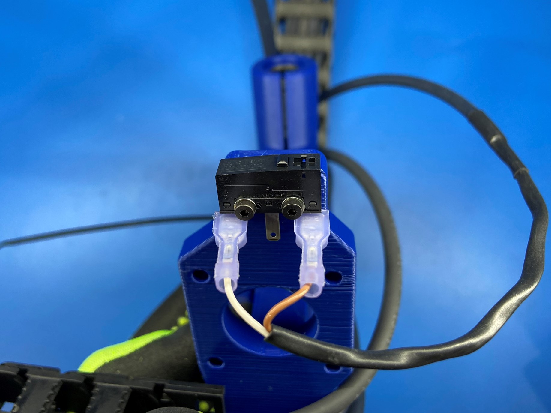
Then bend the two outside tabs on the switch and connect the white and brown wire (Brown wire goes to the tab by the button on the switch. With a cable tie secure the Z max endstop wires along the edge of the x end motor as pictured. [reference#4].
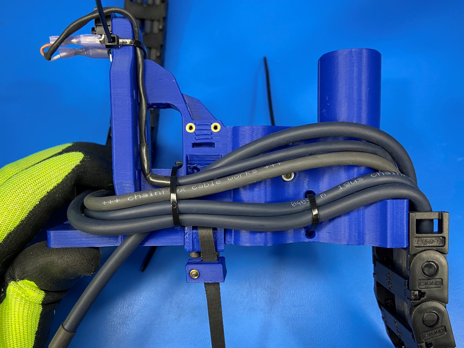
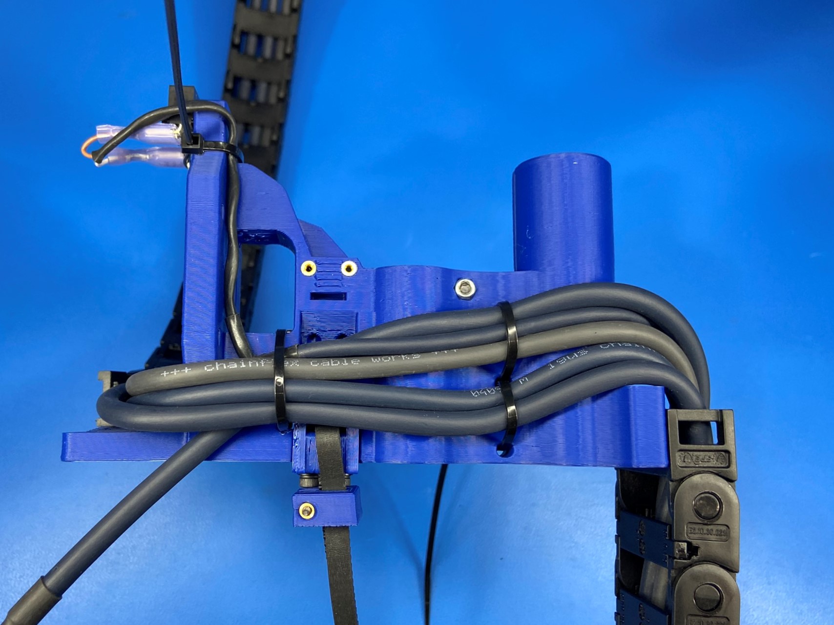
Follow the YELLOW Circle and Arrow.
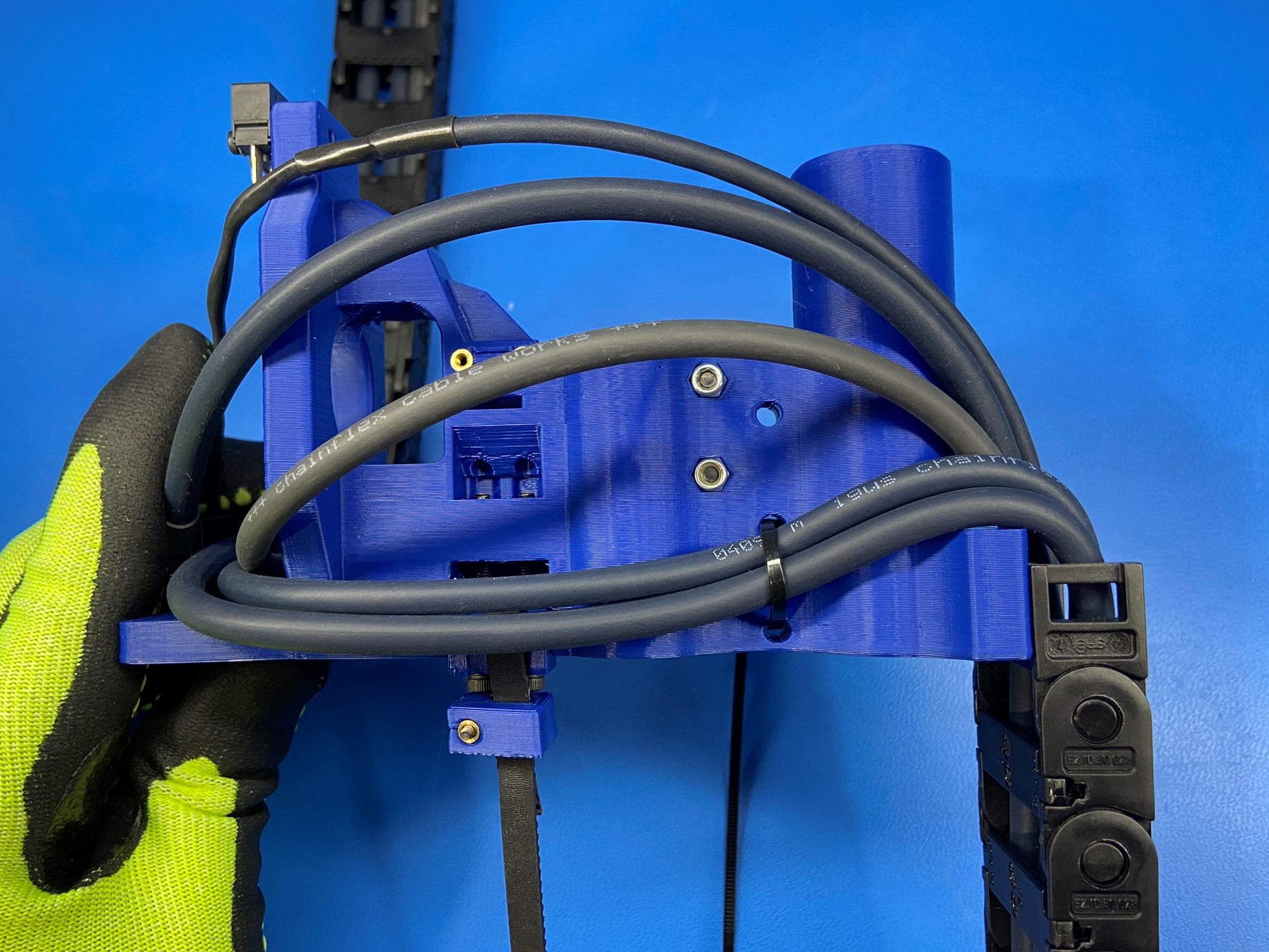
Using 1x cable tie, secure the five wires to the cable mount area nearest the motor mount. The cable tie head must be by the YELLOW arrow. [reference#5]
Make sure the X motor wire is crossed under the other wires
Follow the GREEN Circle and Arrow Then with a cable tie, following the GREEN circle and arrow secure the three wires to the cable mount area above the cable tie securing the two wires. The cable tie head must be by the GREEN arrow. [reference#6]
[reference#7] Shows where the cable ties head should be located
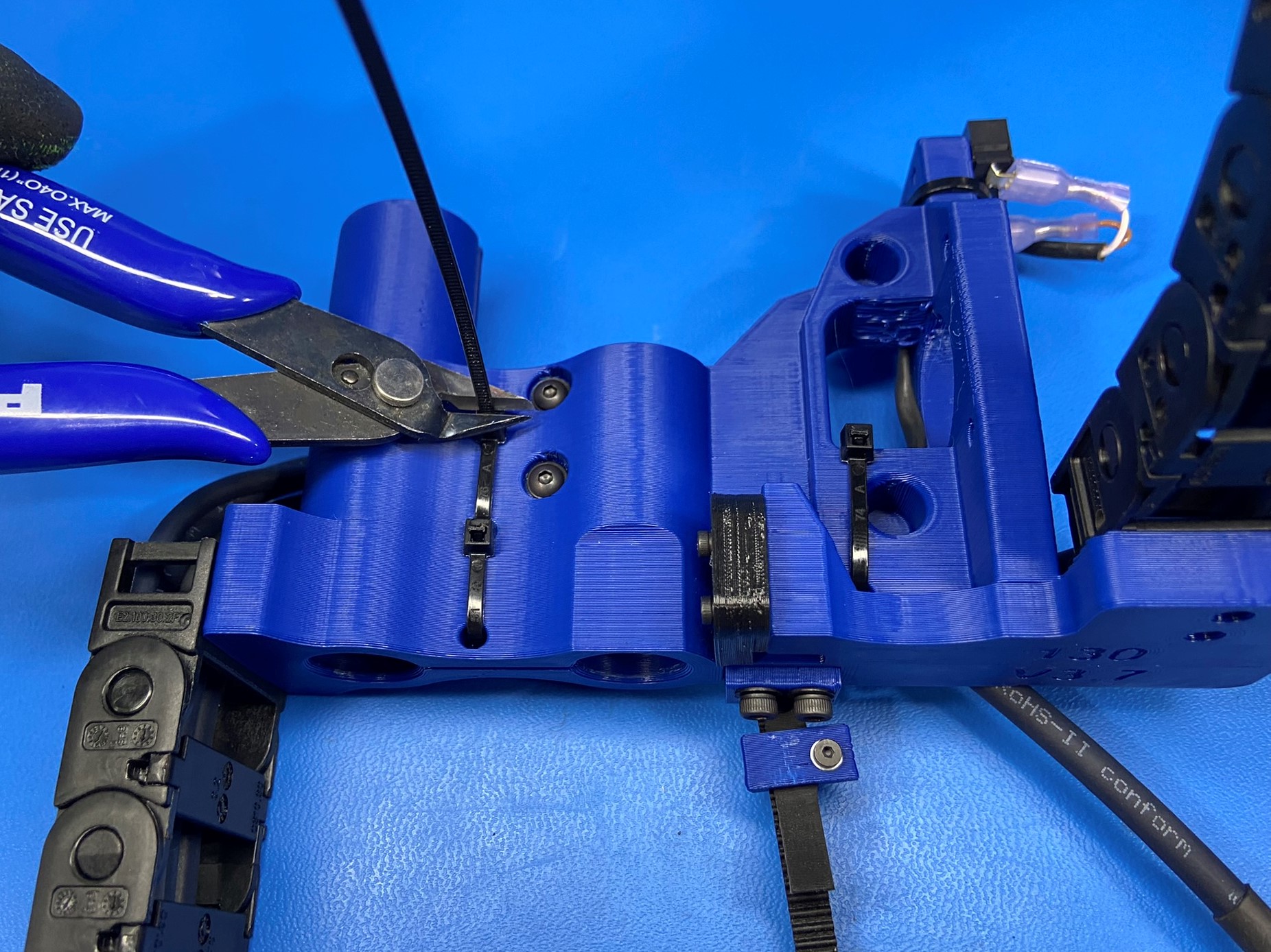
Cut all cable ties flush, assembly should look exactly as pictured.


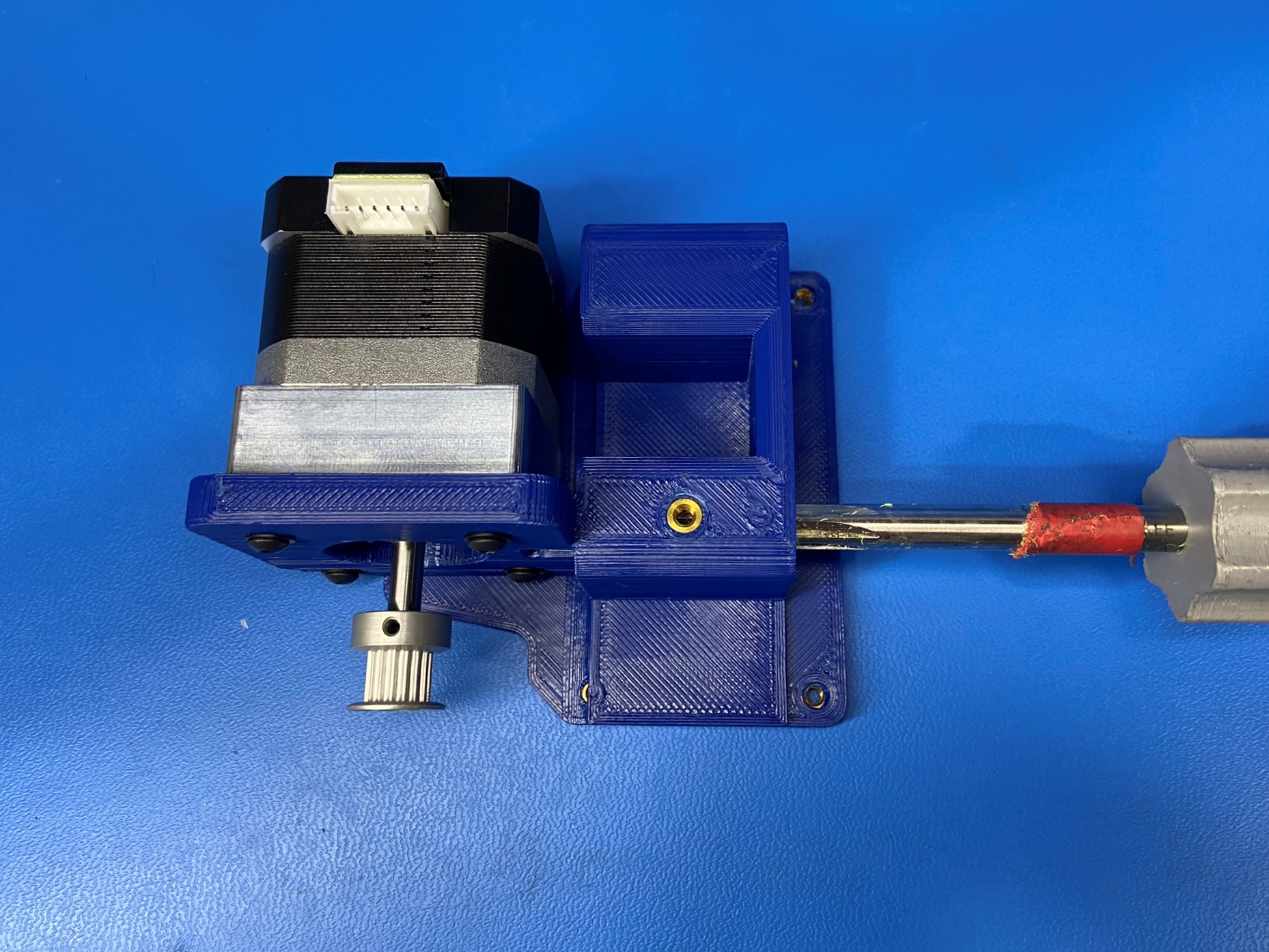
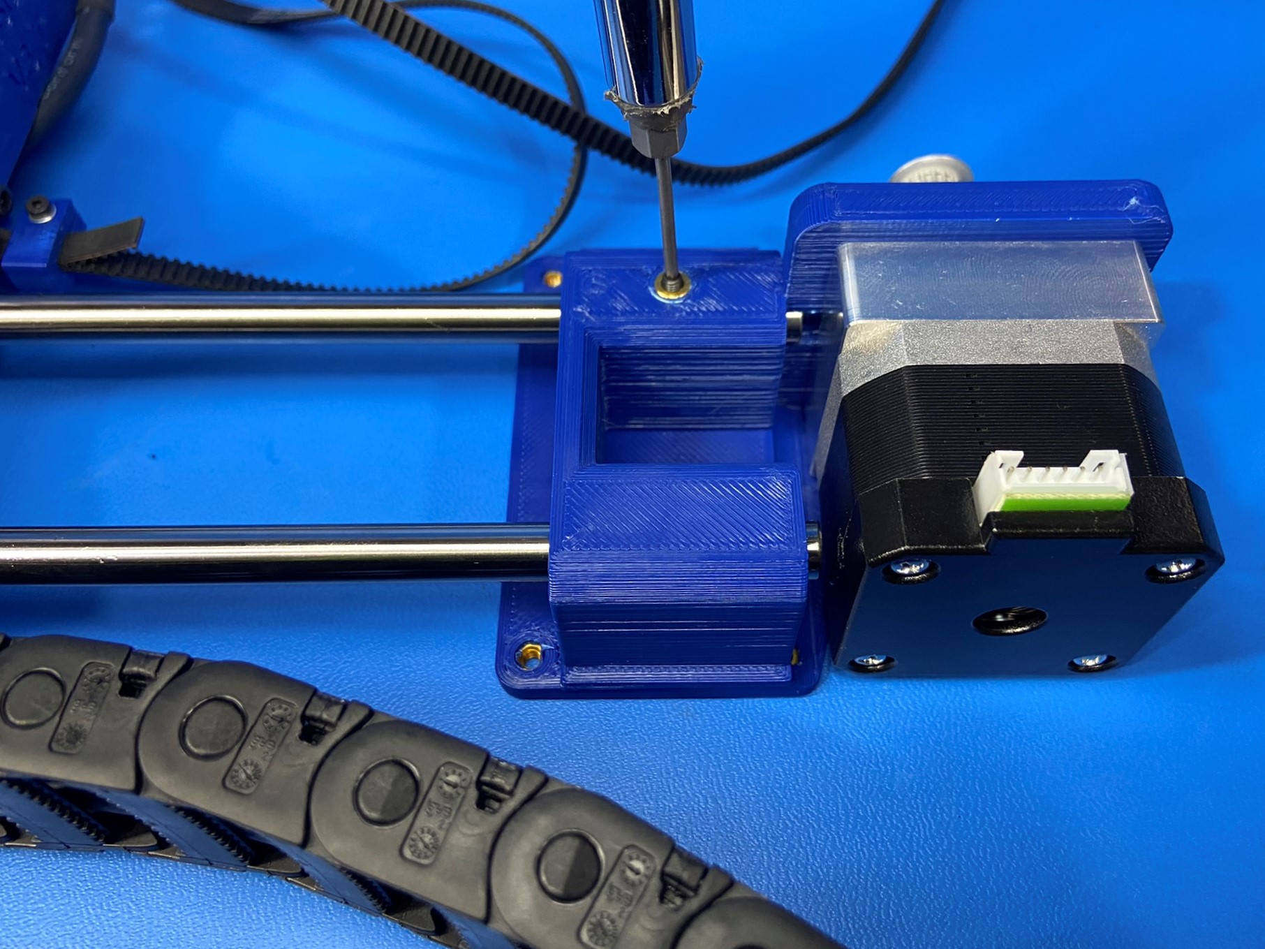
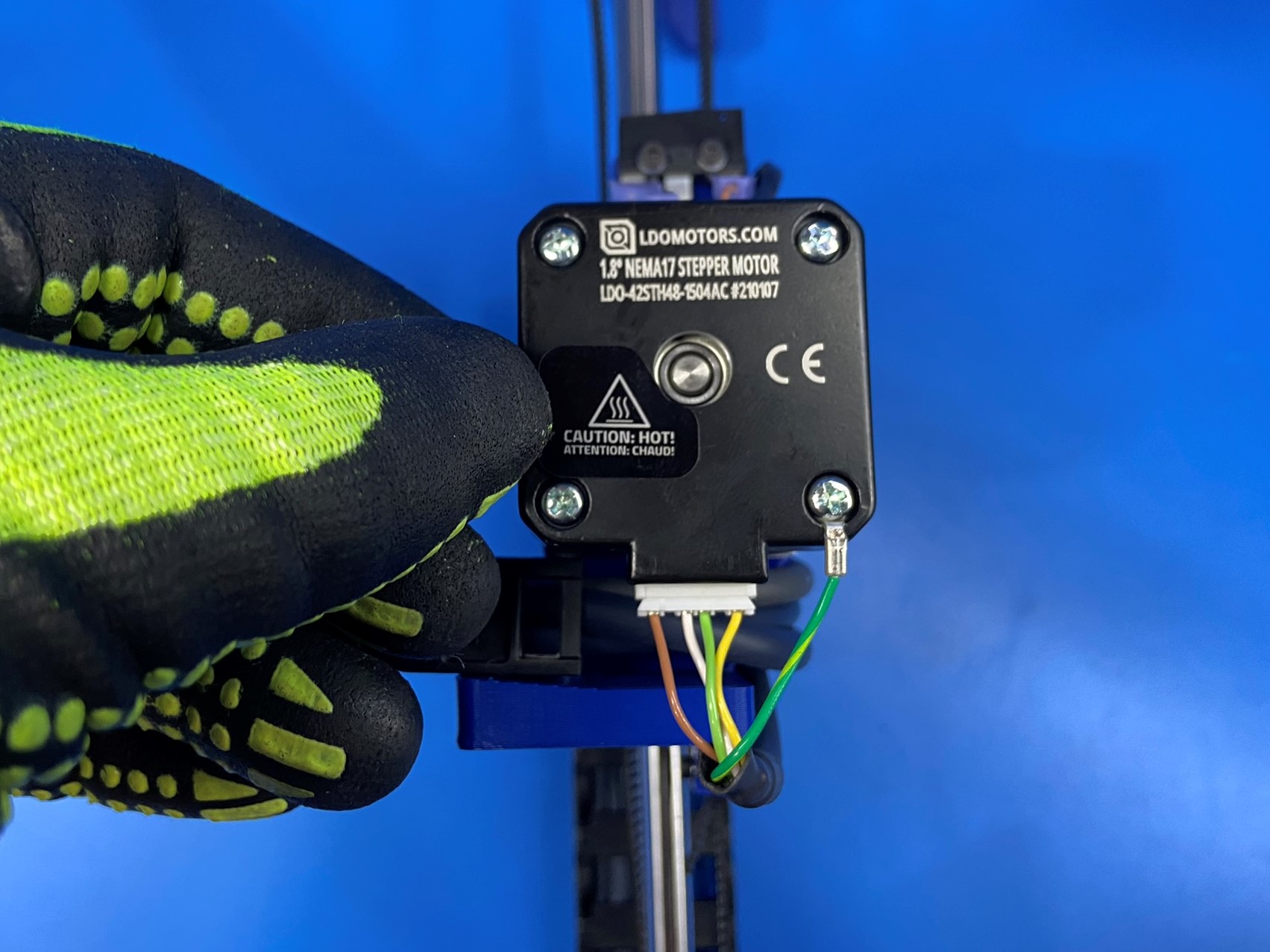
Using the Mini 2 motor jig attach a timing pulley [HD-MS0033] to a NEMA motor [EL-MT0068] , ensure one of the pulley set screws is aligned with the flat segment of the motor shaft, secure pulley in place with two set screws already installed in the pulley, tighten screws securely.
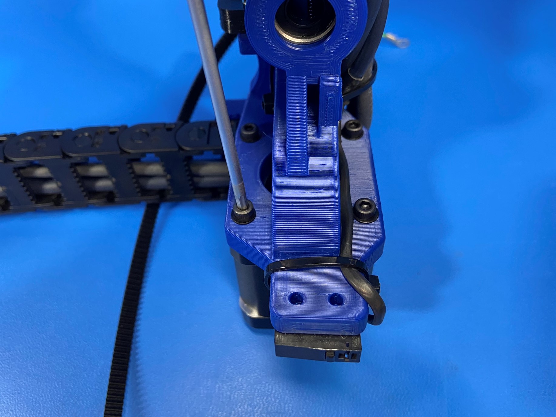
Attach the motor (with the connector pointed down toward the bottom of the X end motor assembly) to the X end motor assembly with 4x- M3x12 SHCS [HD-BT0039] with M3 washers [HD-WA0038].
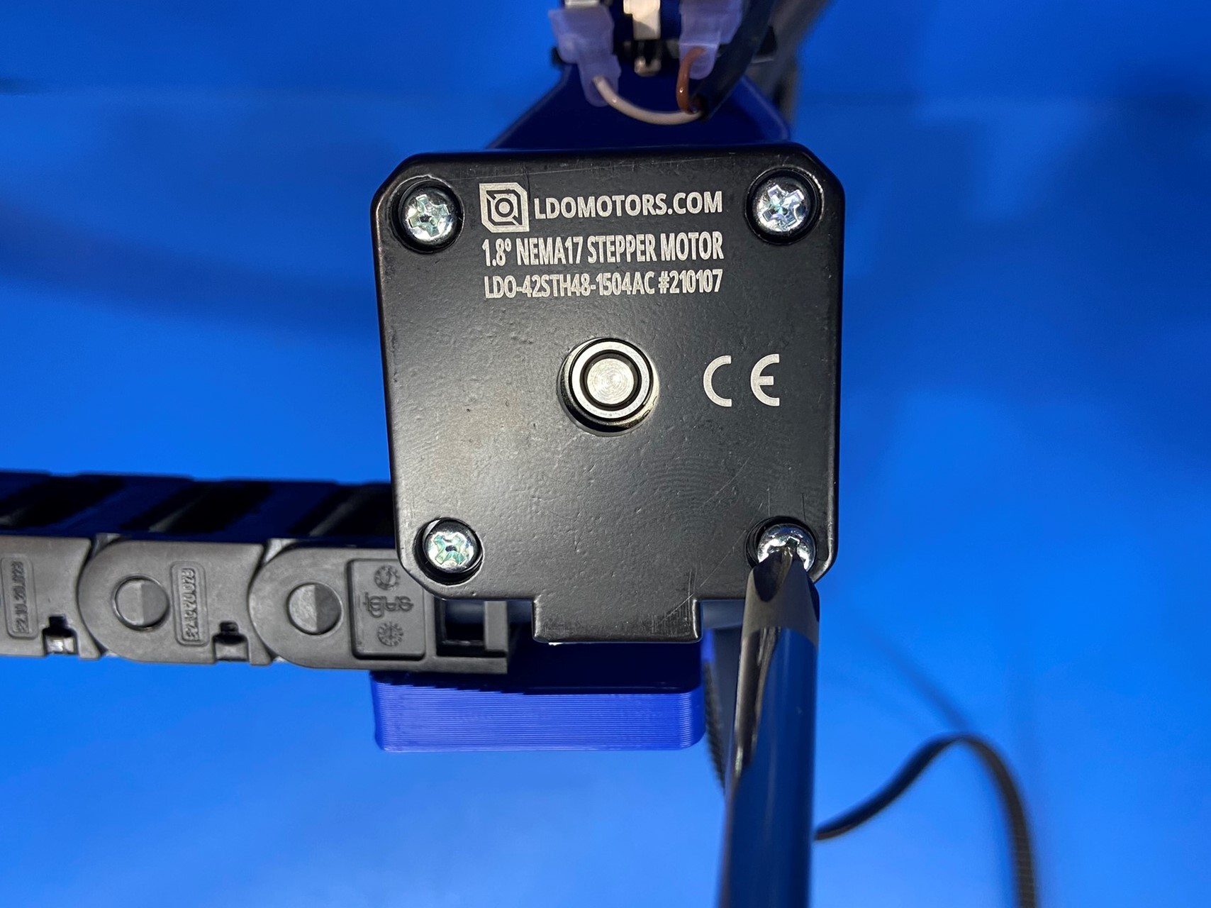
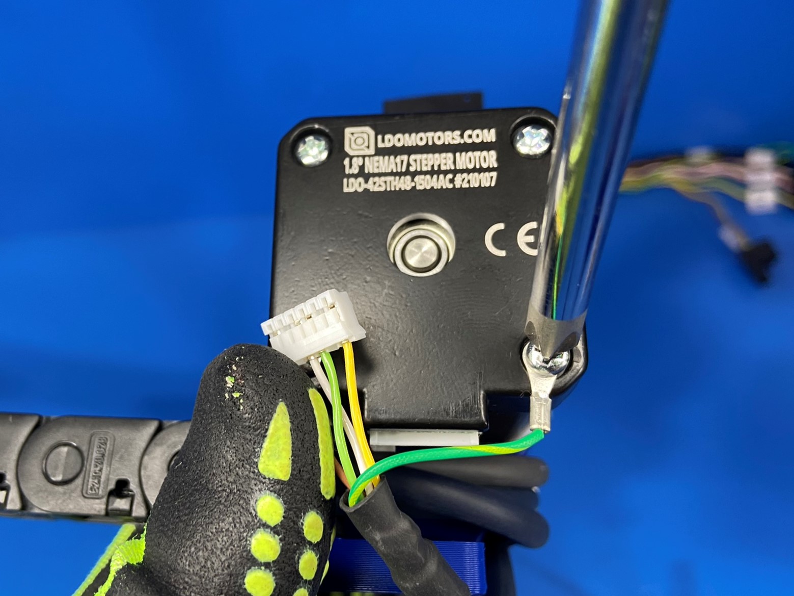
Remove the lower right phillips head screw from the back of the motor just installed [reference#8], install the screw into the ring terminal from the X Motor cable, re-install the screw until the head is again recessed and tight.
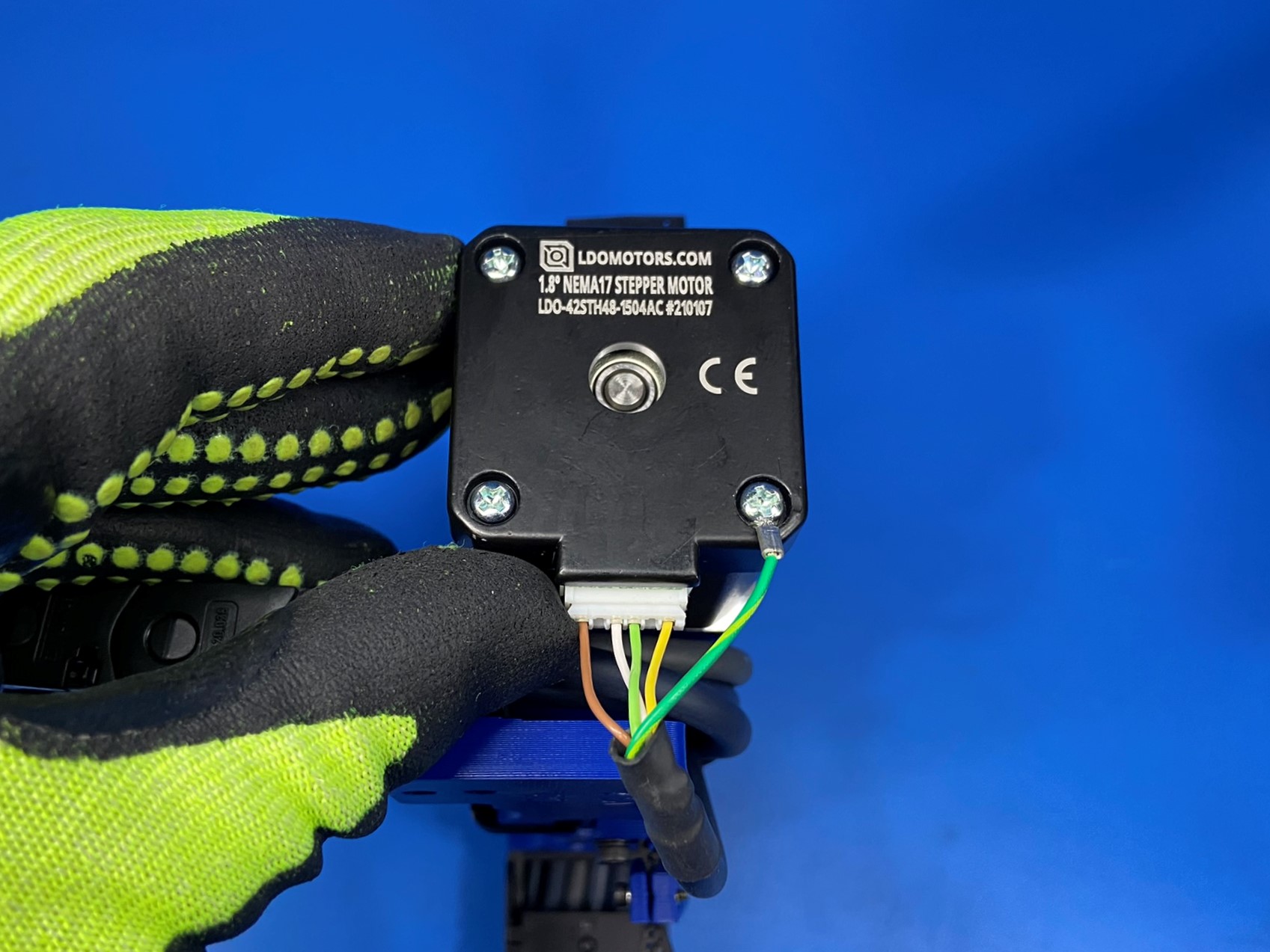
Connect the JST connector to the motor as pictured.
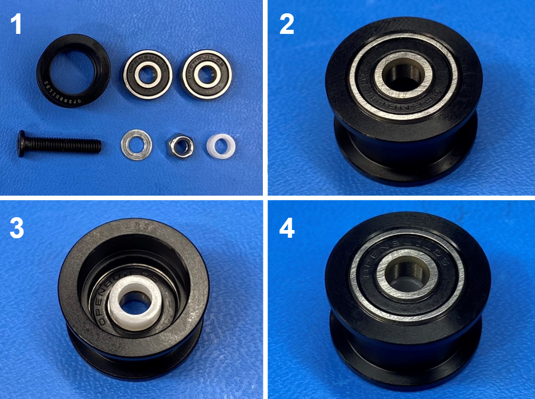
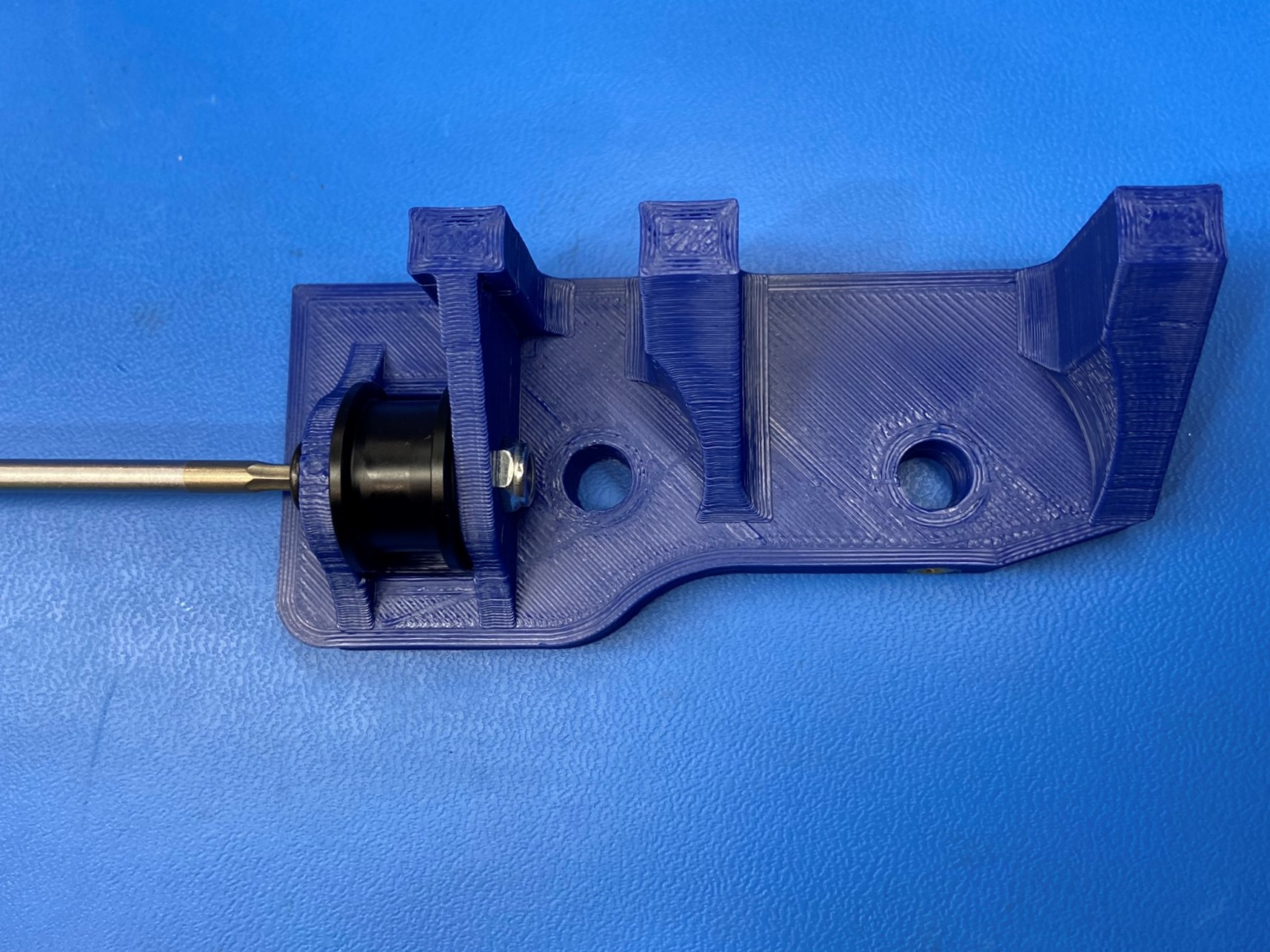
Open the smooth idler pulley wheel kit [HD-MS0412] and place 1x bearing inside the idler.
Then flip the idler over and place a spacer over the bearing making sure the holes align then place a bearing inside the idler sandwiching the spacer between the two bearings.
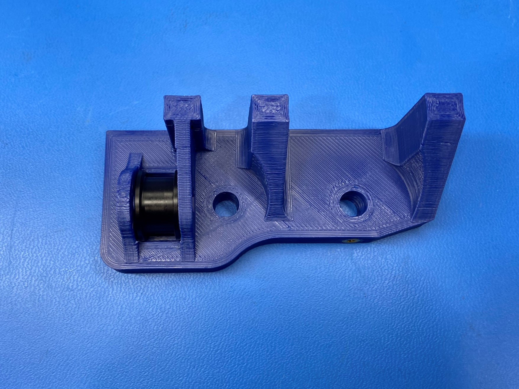
Now place the idler inside the idler slot on the Z upper left, take the screw and slide the washer over it. Then align the screw with the holes on the bearings and slide the screw through.
Thread the screw into the locknut to secure the idler inside the Z upper left. Make sure not to over tighten, the idler should be able to freely spin
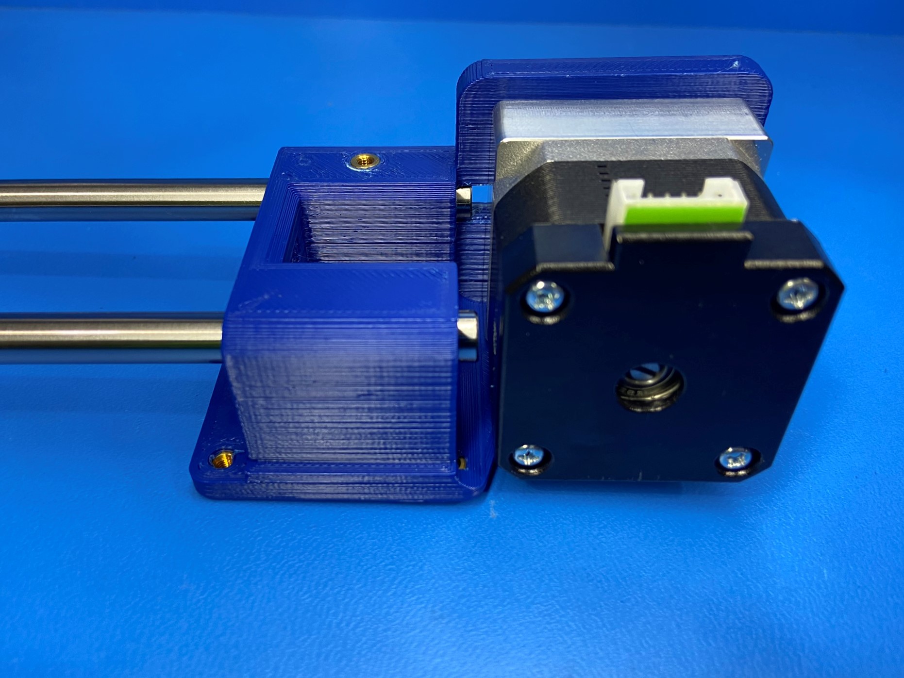
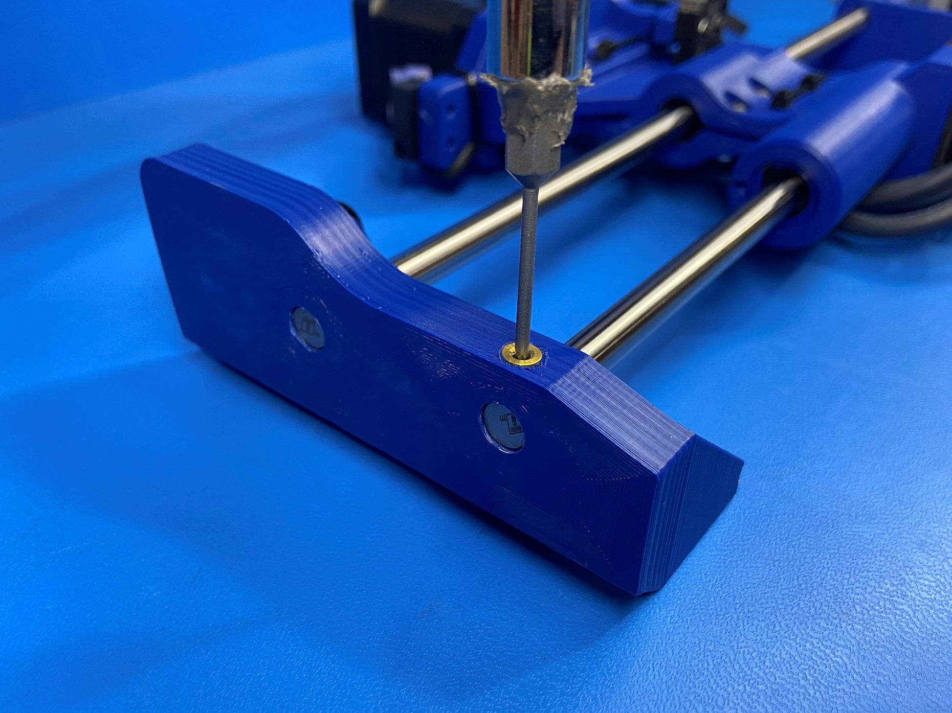
Using an 8mm part reaming tool, ream both smooth rod holes on the Z lower printed part [PP-GP0310].
Note: Keep the tool straight and to not remove too much material which would result in a loose fitting rod and do NOT touch the reaming tool to the motor.
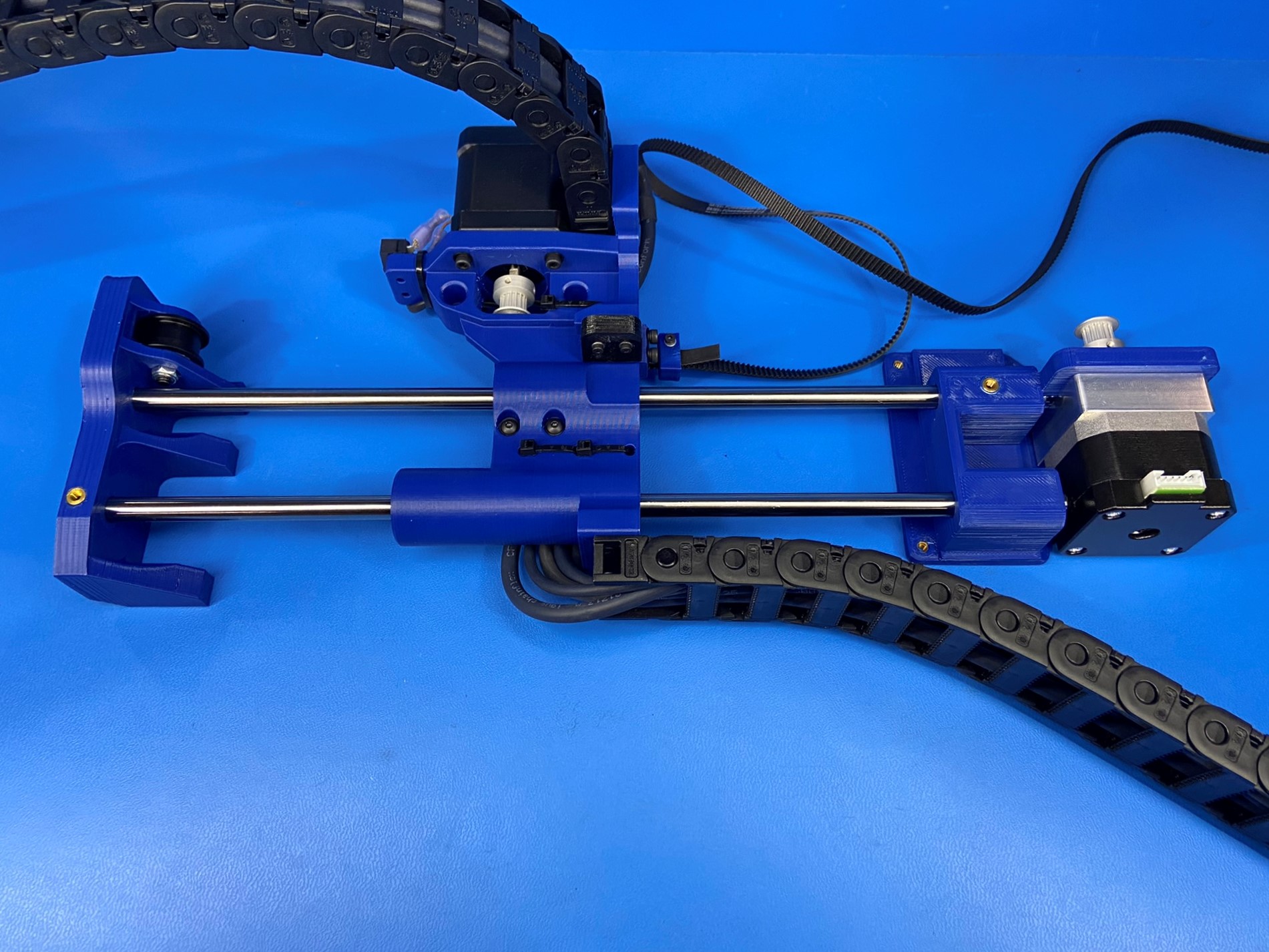
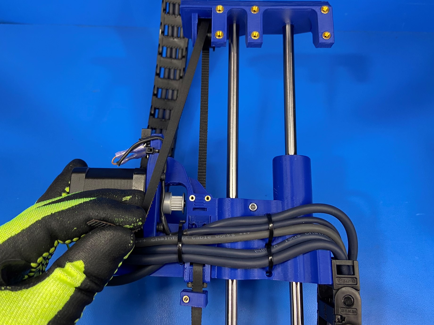
Install 2x hardened steel rods [HD-RD0078] into the Z lower [PP-GP0310]
Slide the X end motor assembly (with cables, switches, and motor attached) onto the steel rods as pictured.
Using an 8mm part reaming tool, ream the two 8mm smooth rod holes on the Z upper left printed part [PP-GP0309].
Note:Take care to keep the tool straight and to not remove too much material which would result in a loose fitting rod.
Install the Z upper left [PP-GP0309] to the end of the smooth rods opposite the Z lower left assembly as pictured. Start with the bottom side and make sure the wires are on the same side as the flat side of the Z lower.
Install 2x M3x6 set screws [HD-BT0012] to the Z lower and upper left near the smooth rods, do not tighten them.
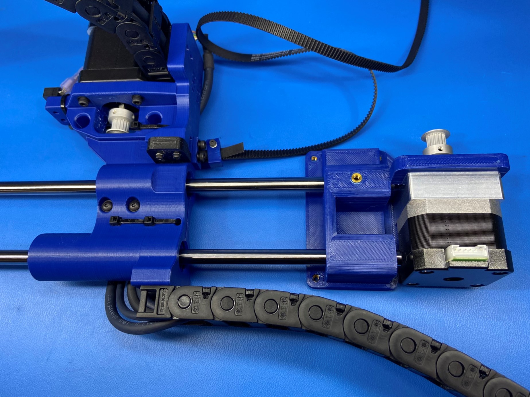
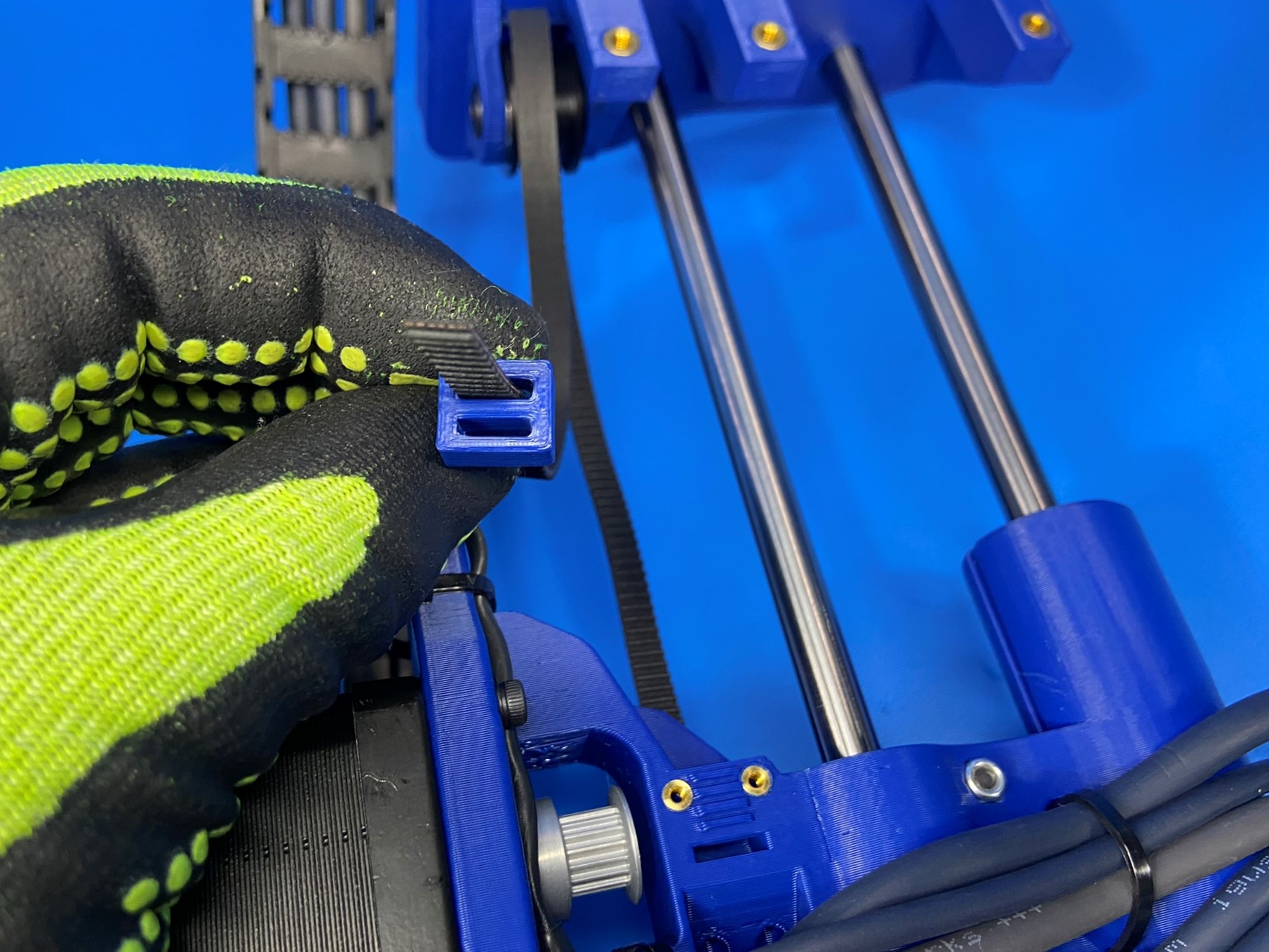
Route the belt (attached to the X end motor assembly during step 3) down around the Z left motor and up through the hole in the X end motor printed part (behind the bump stop). Continue through the idler in the Z upper so that the belt makes a loop back to the X end motor printed part.
Ensure the belt has not been twisted during this process.
Slide the belt through the wide hole on the belt tensioning collar [PP-GP0511] the second slot should be closer to the other side of the belt.
Then push the belt through the slot on the front side of the X end motor until the belt come through the slot on the top side.
The belt should be left loose at this time, secure it in place with one Z belt clamp [PP-GP0512] and two M2x10 SHCS [HD-BT0107] with M2 washers [HD-WA0012]
Then pinch the two sides of the belt together and slide the tensioning collar over both sides locking the teeth together, then fold the tail into the second slot on the tensioning collar.

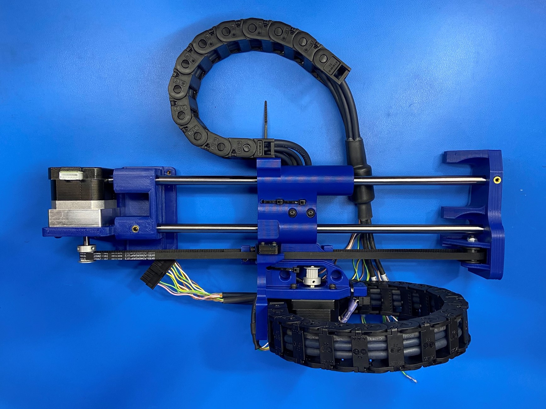
Apply 1x caution hot sticker [DC-LB0154] to the rear of the X motor as shown.
Make sure the wires from the X extruder harness are tucked behind the printed corner on the X end motor. If the wires are on the side of this corner they will be damaged from the printer frame. Once the wires are routed above the corner you can place 1x cable tie [HD-MS0058] to the cable chain securing the five wires to the right wall of the cable chain.

Lay the assembly flat against table and ensure that none of the wires are sitting against the table.