Open HardwareAssembly Instructions
Guides for installation and assembly of the LulzBot line of products made by FAME 3D LLC.
Guides for installation and assembly of the LulzBot line of products made by FAME 3D LLC.
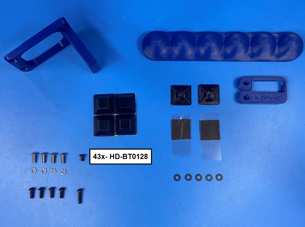
4x- [HD-BT0104] M3x8 BHCS, SST
43x- [HD-BT0128] M3x6 FHCS, Black-Oxide
4x- [HD-BT0137] M3x8 BHCS, Black-Oxide
1x- [HD-BT0146] M3x12 BHCS, Black-Oxide
4x- [HD-MS0054] Rubber Bumper Square
2x- [HD-MS0571] Adhesive Pad
4x- [HD-WA0035] M3 External Tooth Lock Washer
5x- [HD-WA0038] M3 Washer Black-Oxide
1x- [PP-GP0168] Top Frame, White
1x- [PP-FP0170] Left Frame, White
1x- [PP-GP0259] Handle Bar
1x- [PP-GP0265] Lower Strain Relief
1x- [PP-GP0266] Upper Strain Relief Mount
1x- [PP-GP0483] Universal Cable Tie Holder
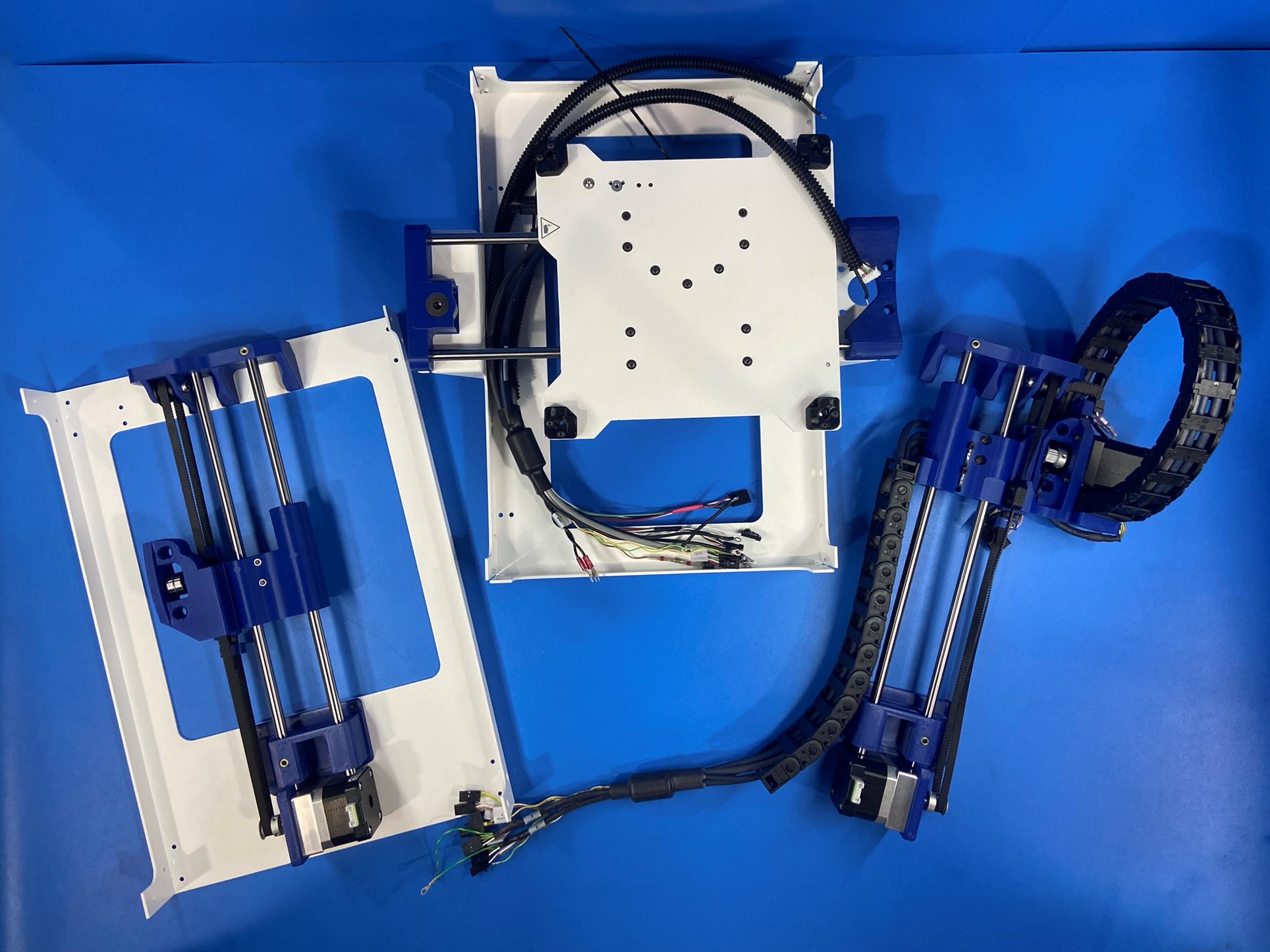
Z-Axis Right
Z-Axis Left
Bed Plate
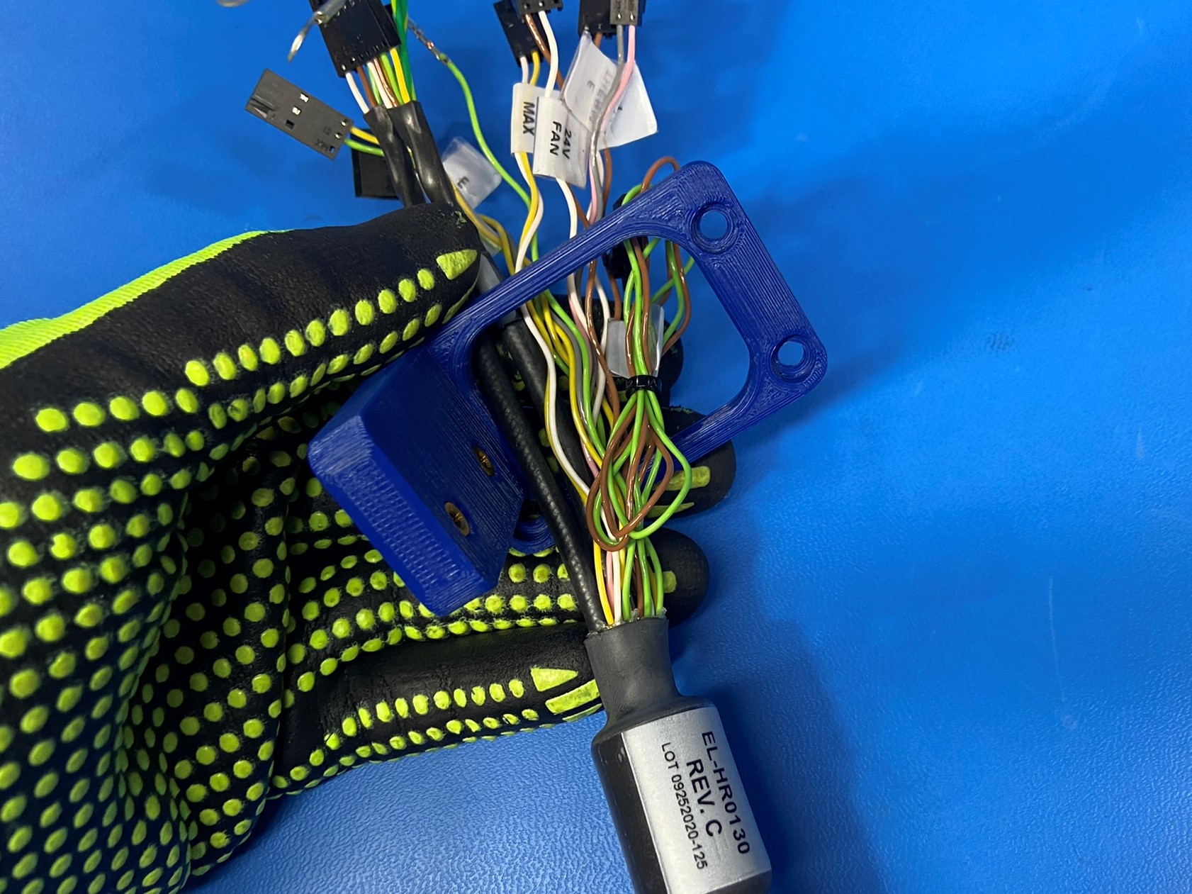
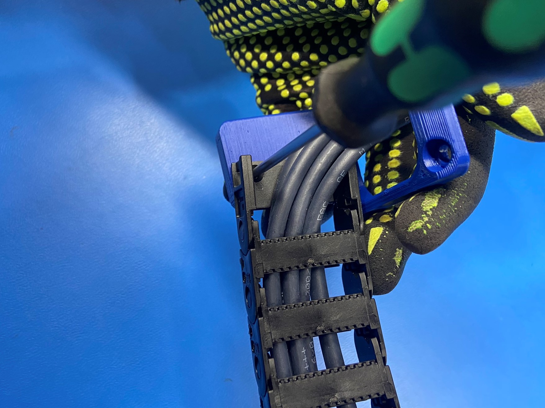
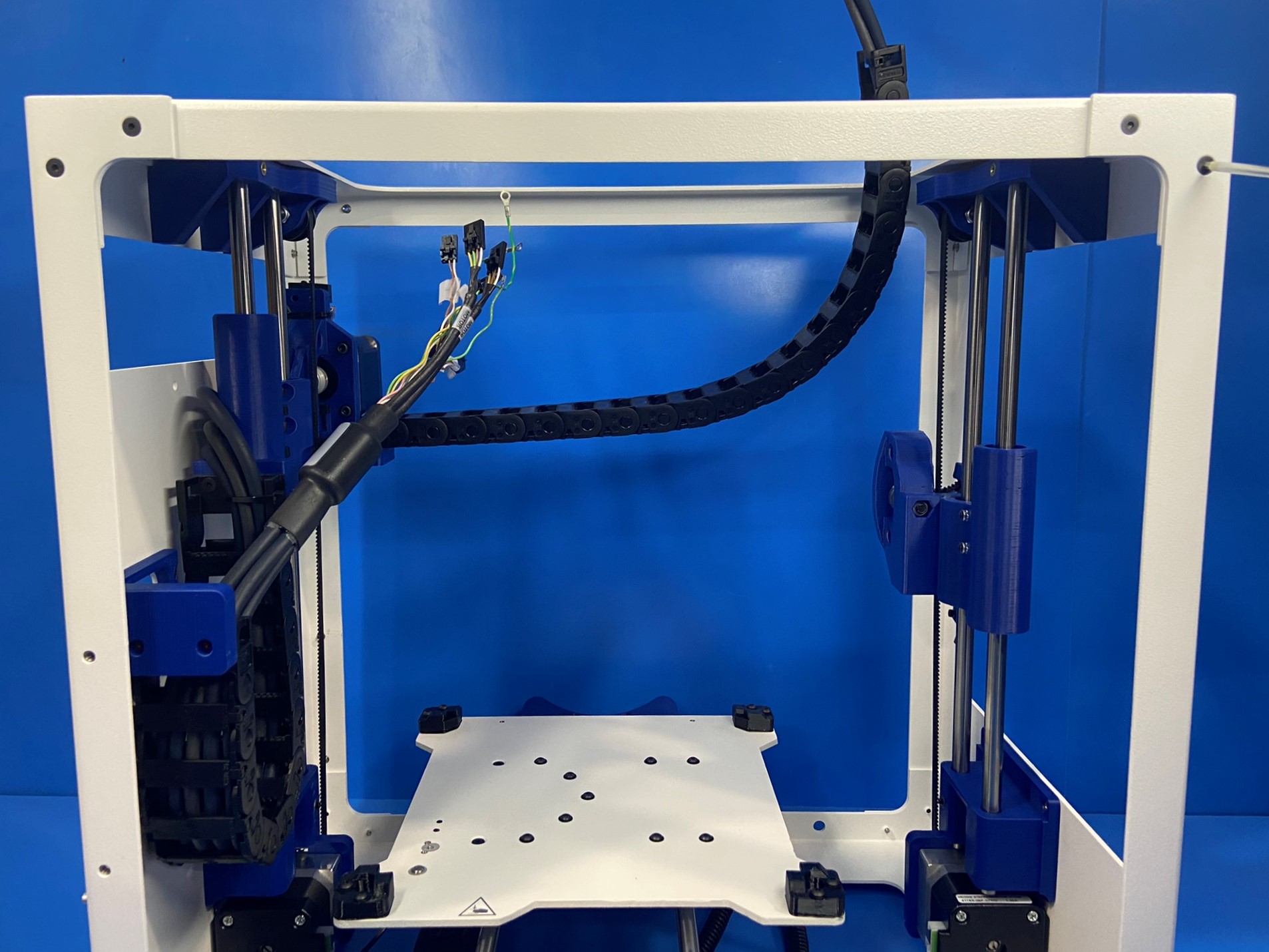
Slide the upper relief mount [PP-GP0266] over the X motor harness that is connected to the left side.
Then using 2x M3x6 FHCS [HD-BT0128] secure the 30mm cable chain mount to the upper relief mount [PP-GP0266] Ensure the cable chain mount is oriented as pictured.
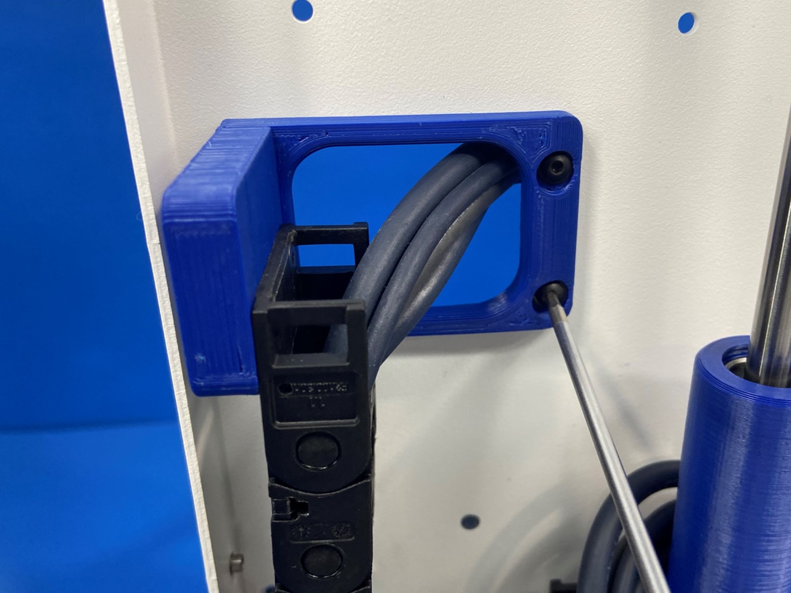
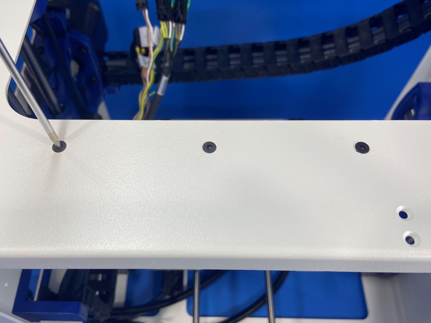
Align the upper strain relief holes with the three holes in the left frame [PP-FP0170]
Secure the upper strain relief to the left frame using 2x M3x8 BHCS [HD-BT0137] with washers [HD-WA0038] and one M3x12 BHCS [HD-BT0146] with a washer [HD-WA0038] in the hole circled in red.

Place the Z axis left assembly on the left frame plate [PP-FP0170]
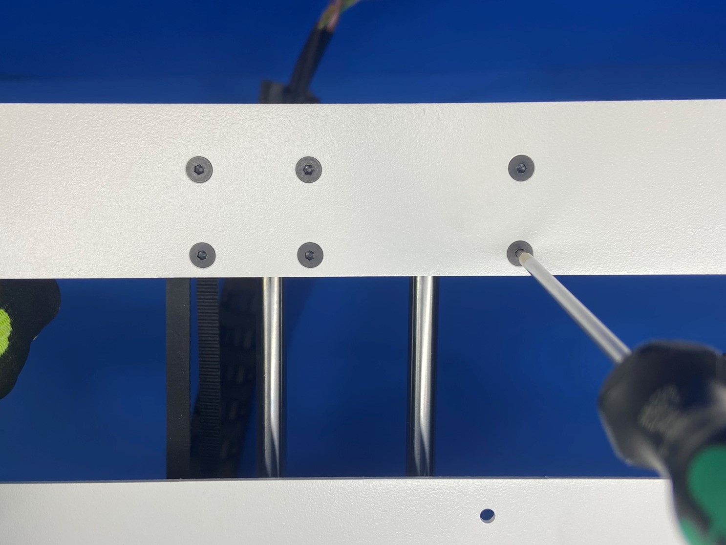
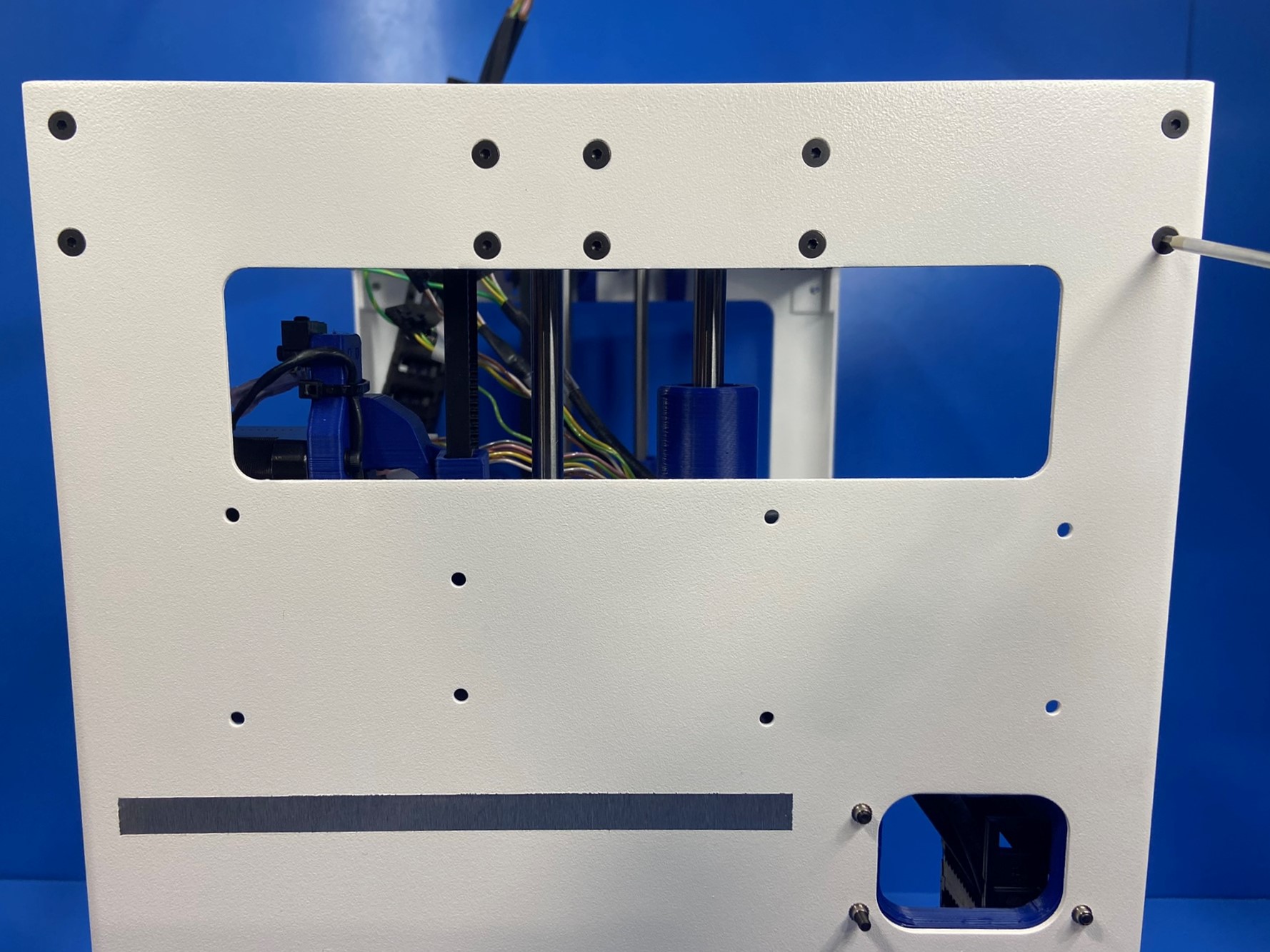
Secure the Z lower left of the Z axis left assembly to the left frame plate with four M3 x 6 FHCS [HD-BT0128], torque to 5 in*lbs
Secure the Z upper left of the Z axis left assembly to the frame assembly with 6x M3x6 FHCS.
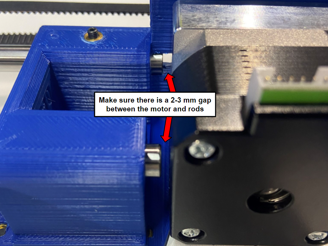
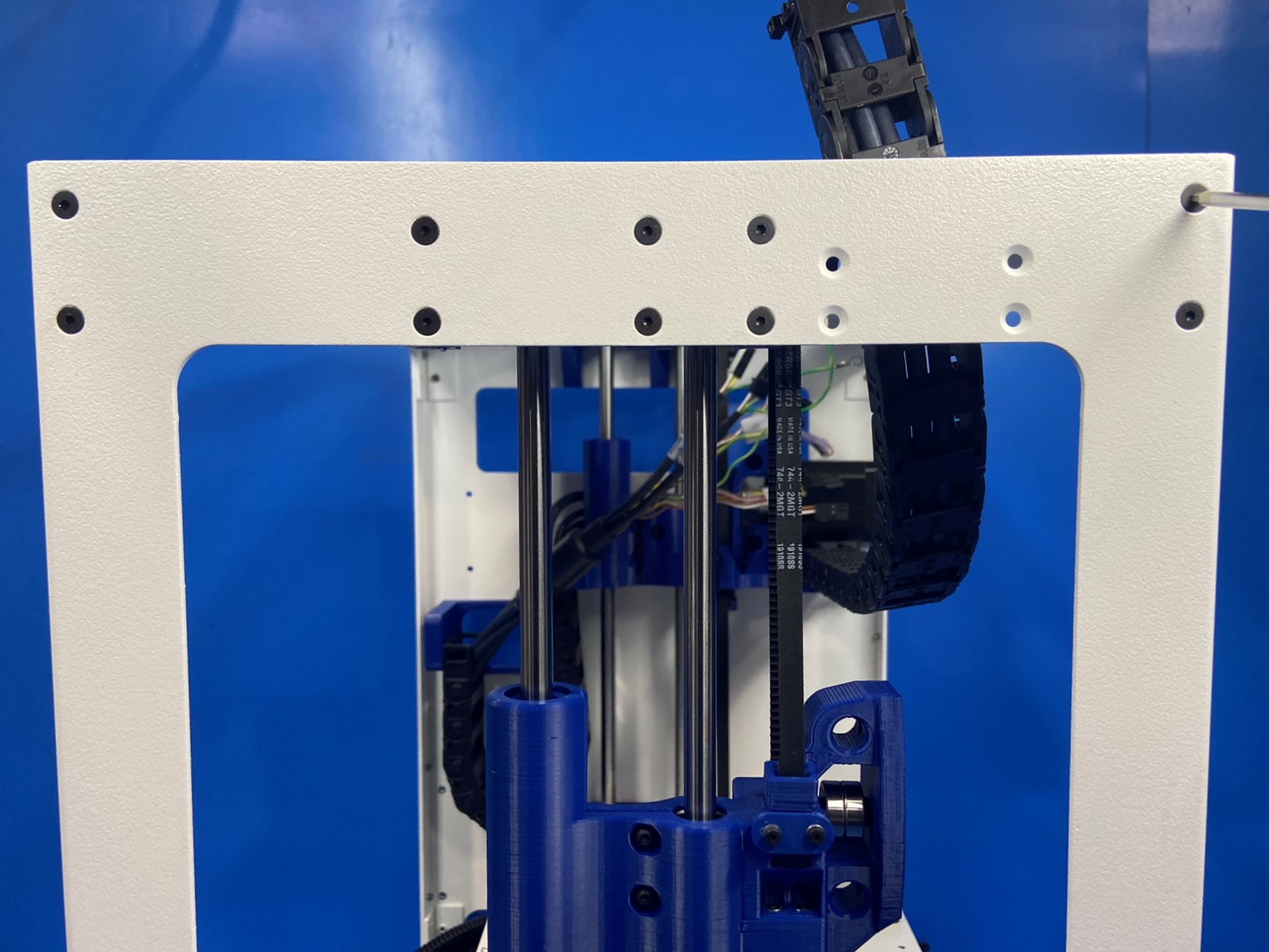
Ensure the Z axis harden steel rods are not making contact with the Z motor, this can cause unwanted noise/vibration, there should be a 2-3mm gap between the motor housing and the bottom of the rods.
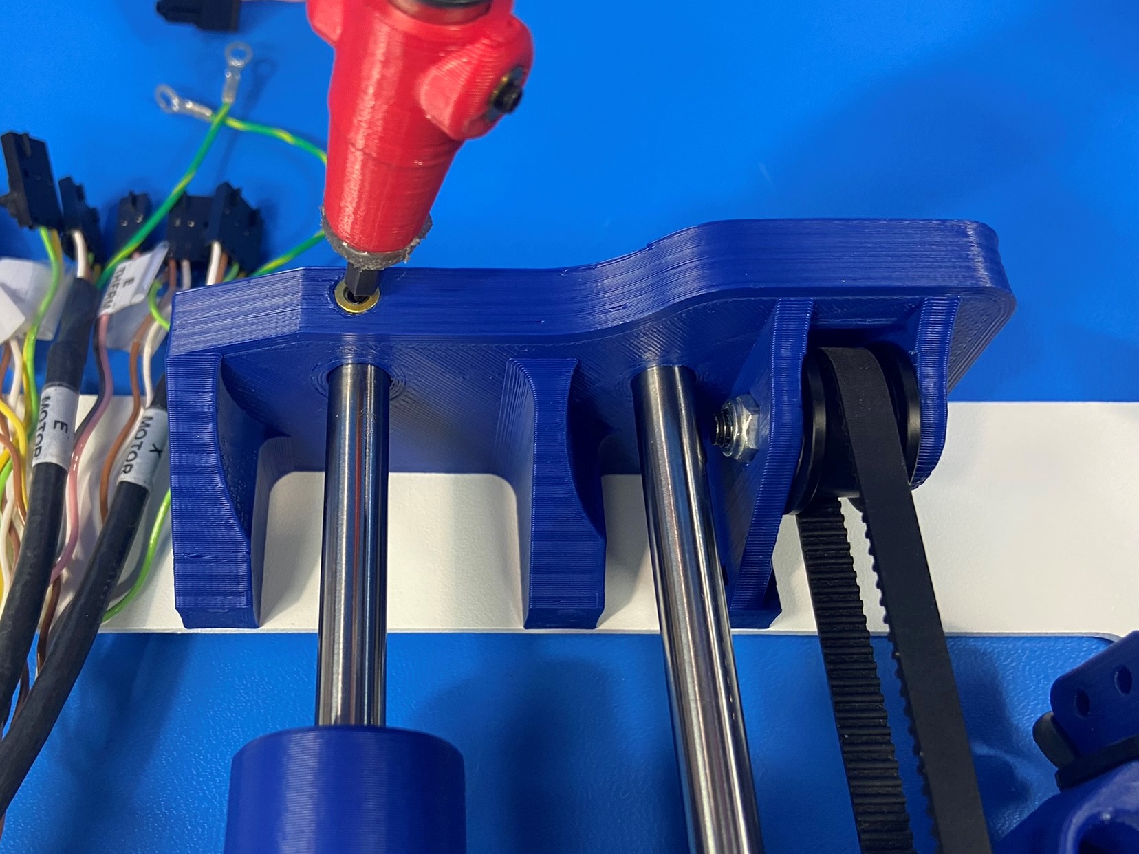
Torque the lower steel rod set screw to 2in*lbs as pictured.
Torque the upper steel rod set screw to 2in*lbs as pictured.


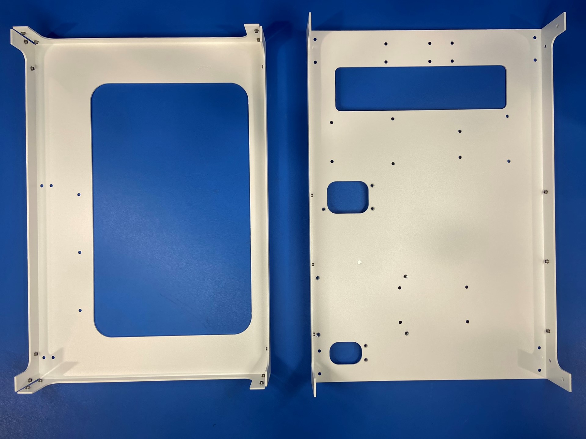
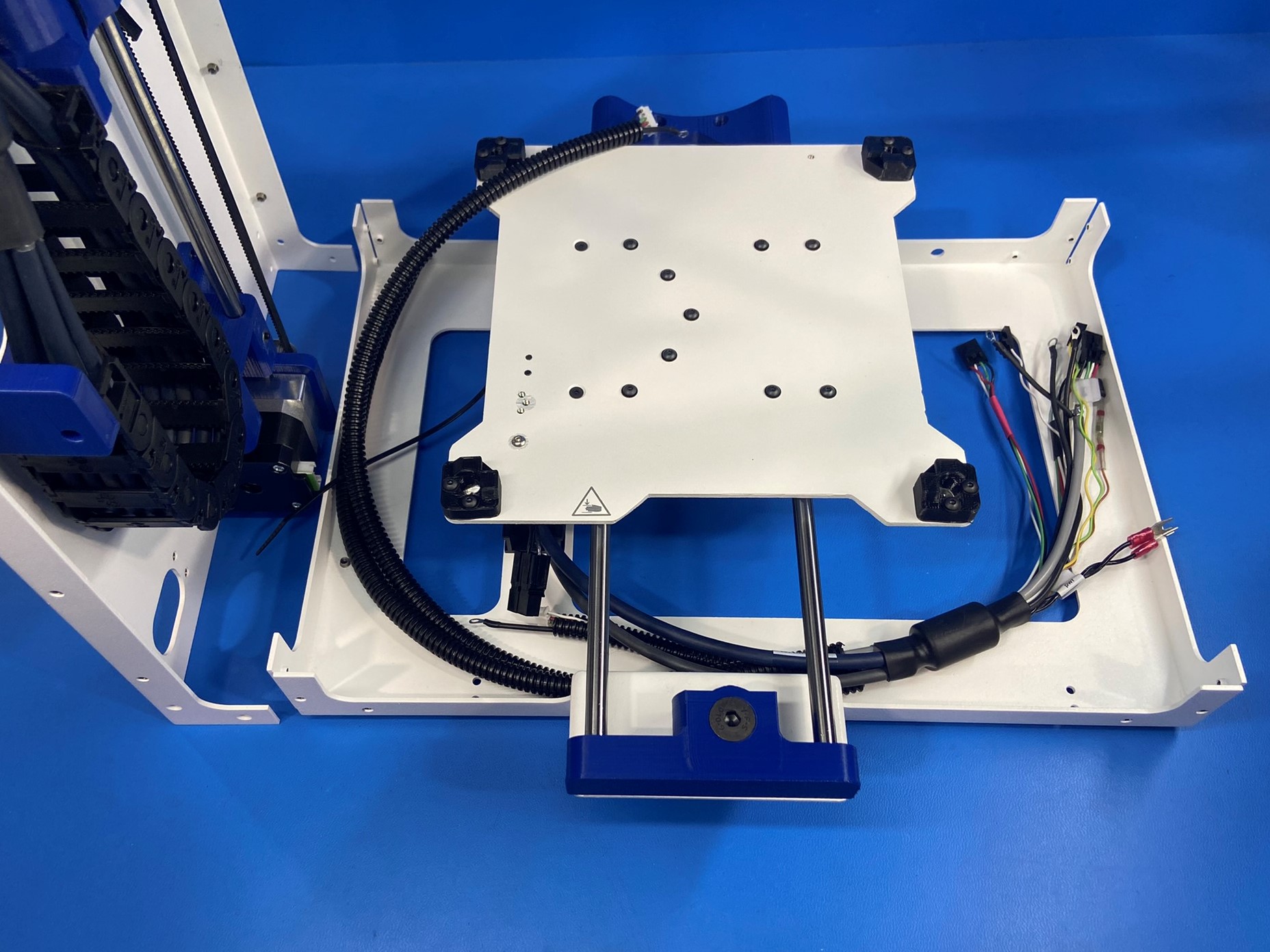
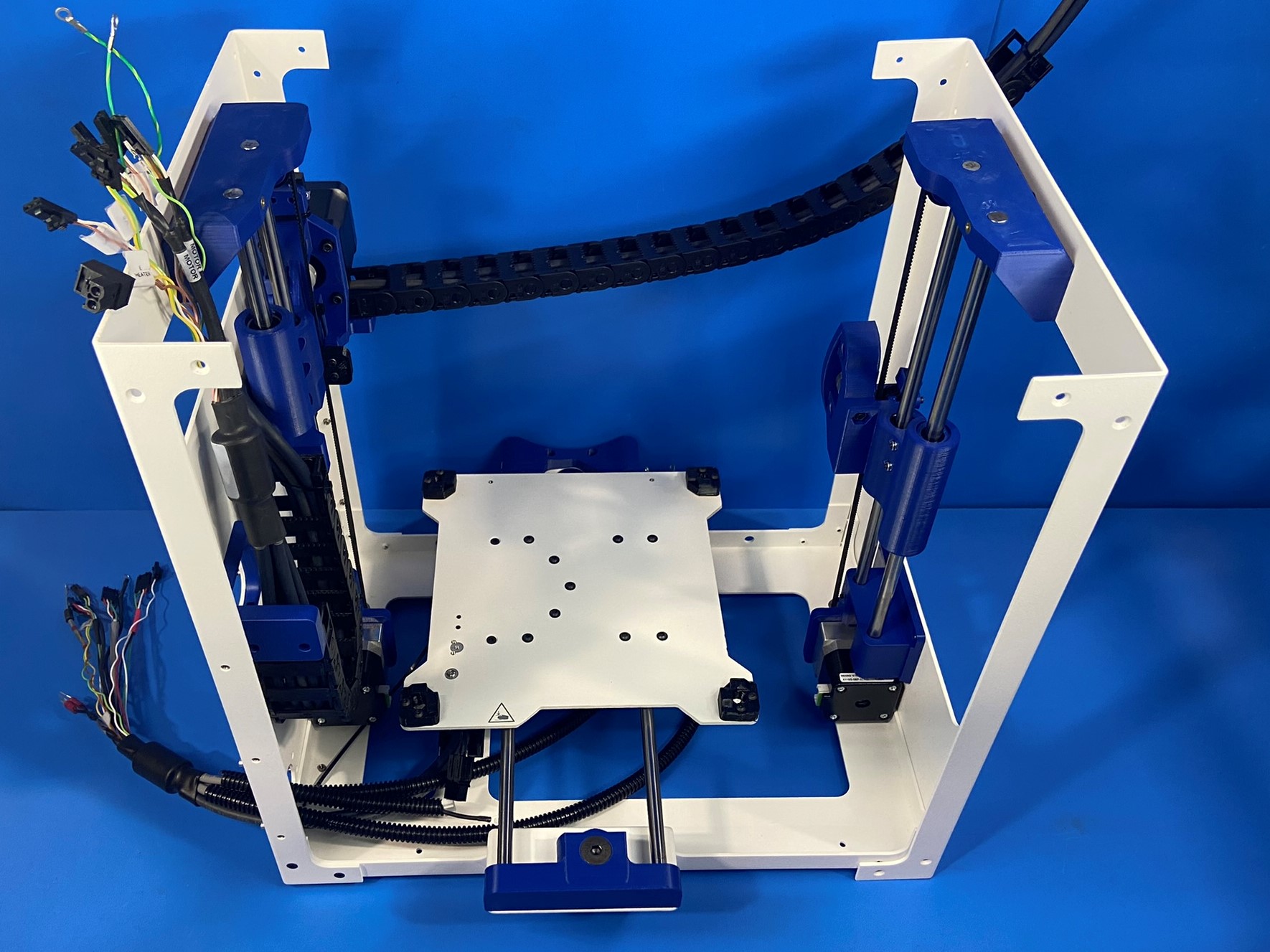
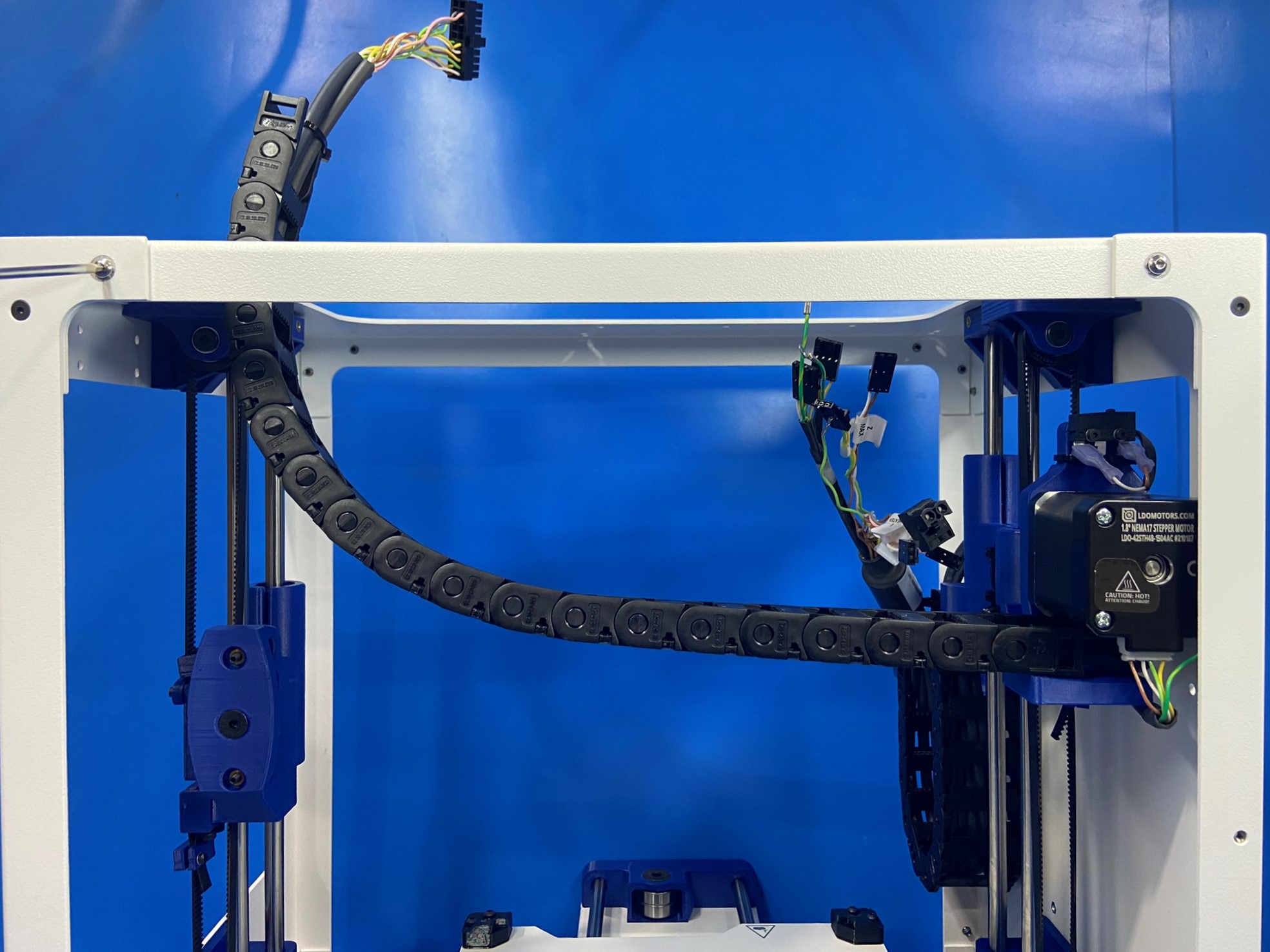
Place the bed plate assembly on work station next to the upright left frame plate assembly
Carefully run the end of the bed harness through the left frame plate [PP-FP0170] as shown
Slide the left frame plate over the bottom frame plate
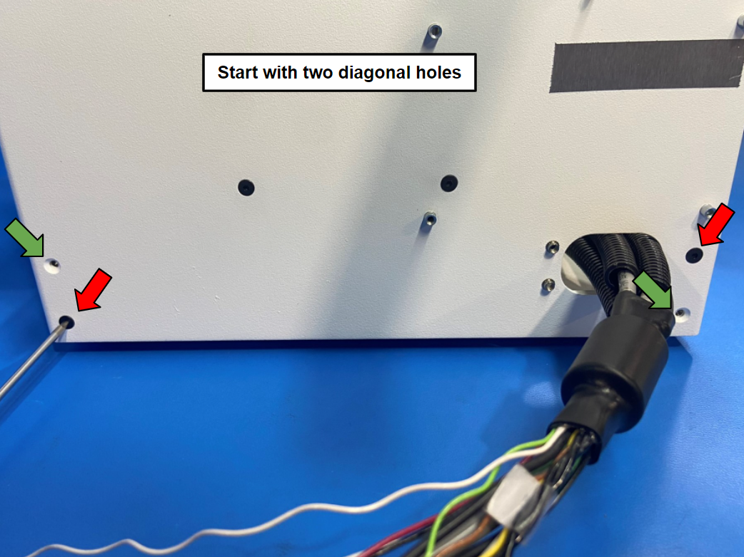
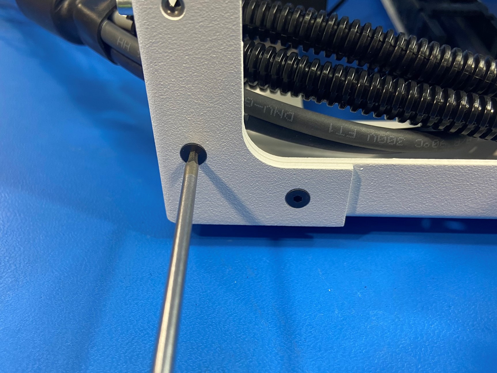
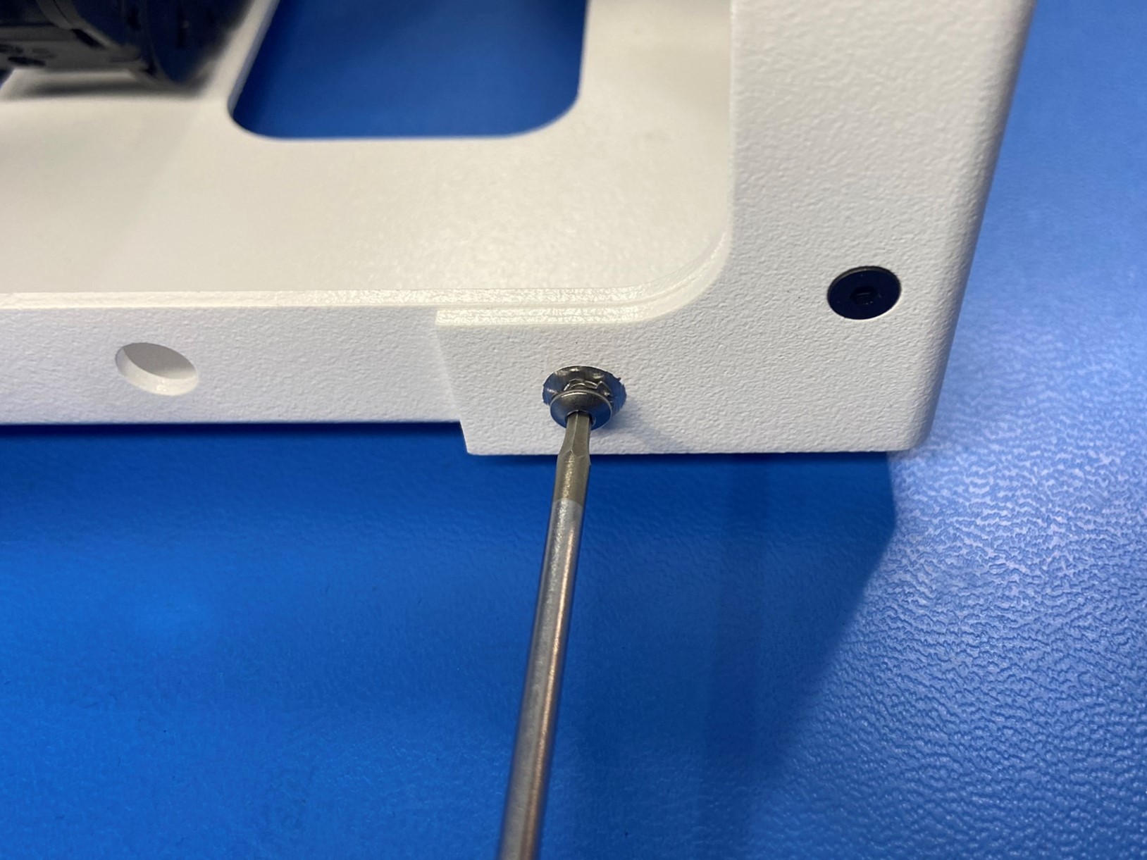
Fasten the left and bottom frame plate together using 7x M3x6 FHCS [HD-BT0128] and 1x M3x8 BHCS [HD-BT0104] with 1x M3 external tooth lock washer [HD-WA0035]
Using the same process as the Z axis left, slide the Z axis right assembly over the bottom frame plate and make sure the holes are aligned.
Fasten the right and bottom frame plate together using 7x M3x6 FHCS [HD-BT0128] and 1x M3x8 BHCS [HD-BT0104] with 1x M3 lock washer [HD-WA0035]

Slide the top frame plate [PP-FP0168] in between the left and right frame plates. Ensure the handle mounting location on the top frame is oriented to the front (idler side) of the printer.
Align the holes in the frame pieces
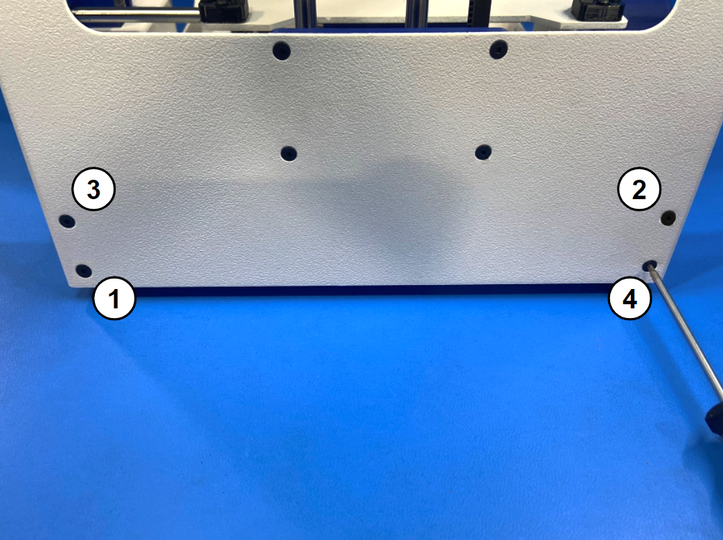
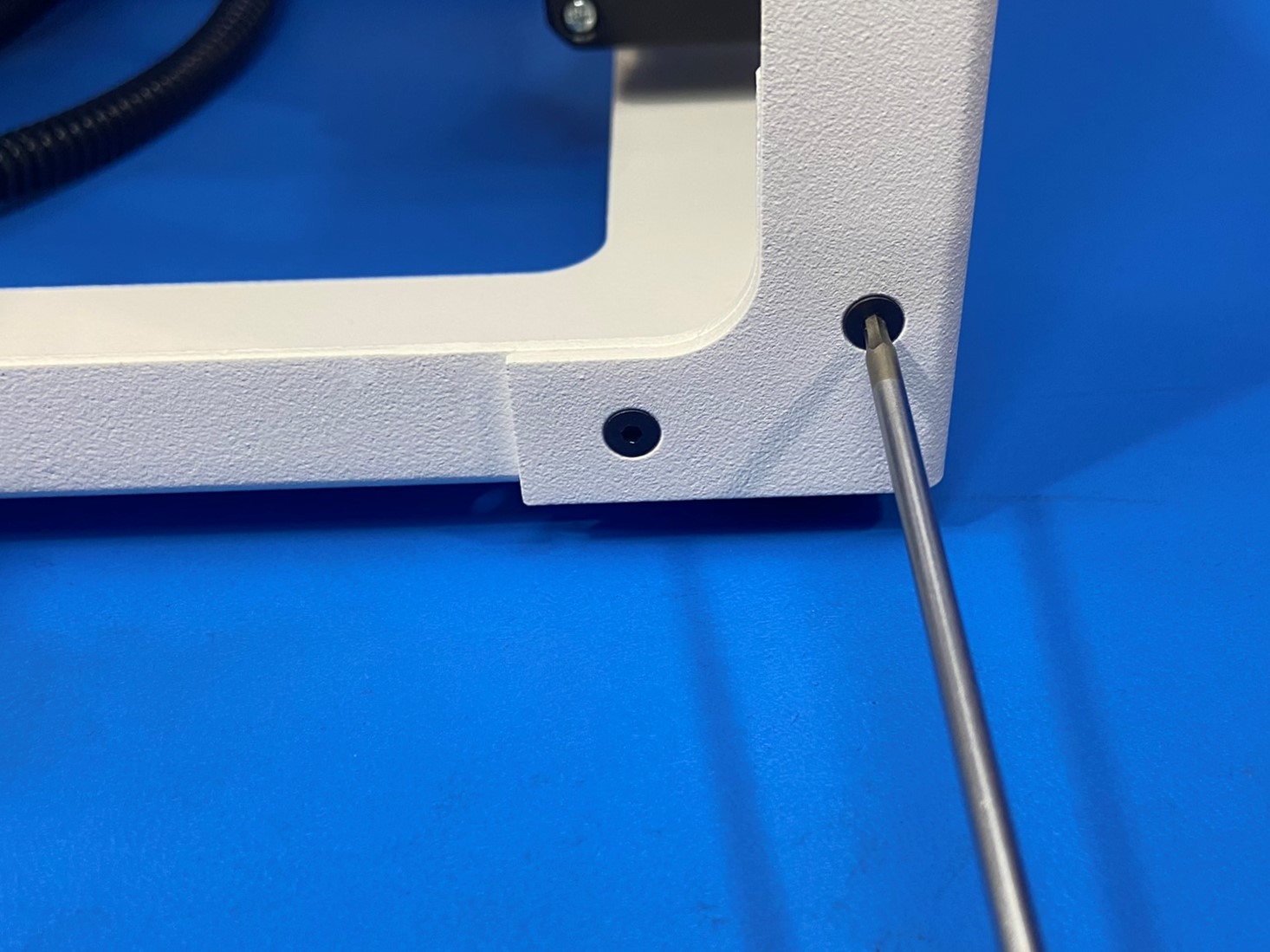
On the front (idler side), fasten 4x M3x6 FHCS [HD-BT0128] screws into the top left and right corners.
Using the same process as the other frame plates secure the top frame plate to the left and right frame plates. Use 14x M3x6 FHCS [HD-BT0128] and 2x M3x8 BHCS SST [HD-BT0104] with M3 lock washers [HD-WA0035] in the two bottom holes on the back side.
Once the top frame plate is secured to the printer frame, align the handle [PP-GP0259] with the three holes on the front side of the top frame plate.
The use 3x M3x6 FHCS [HD-BT0128] to secure the handle to the top frame plate.

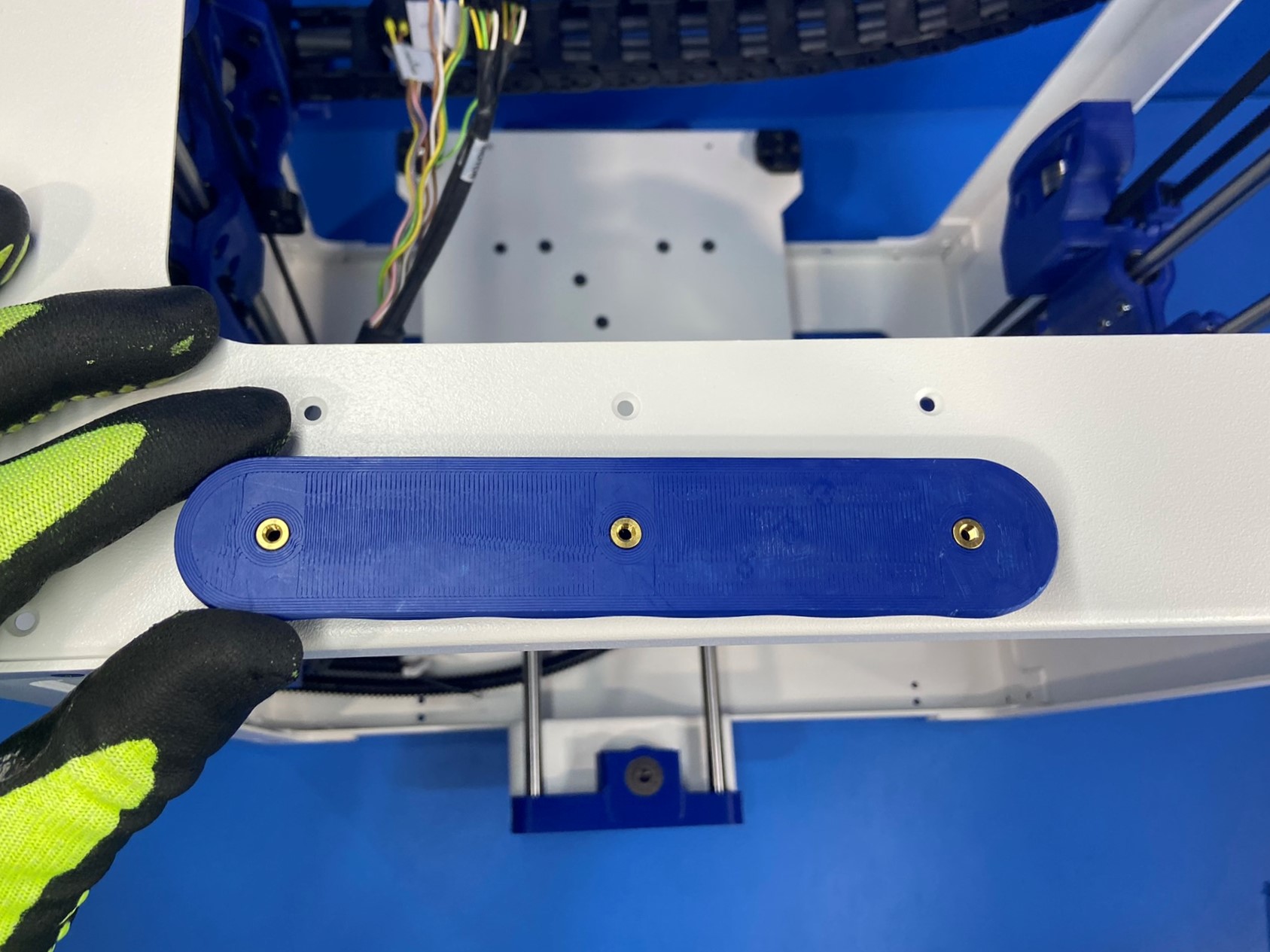
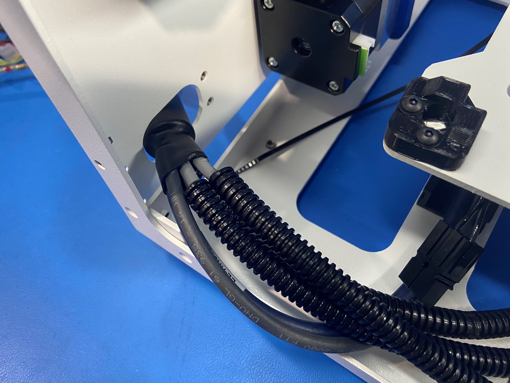
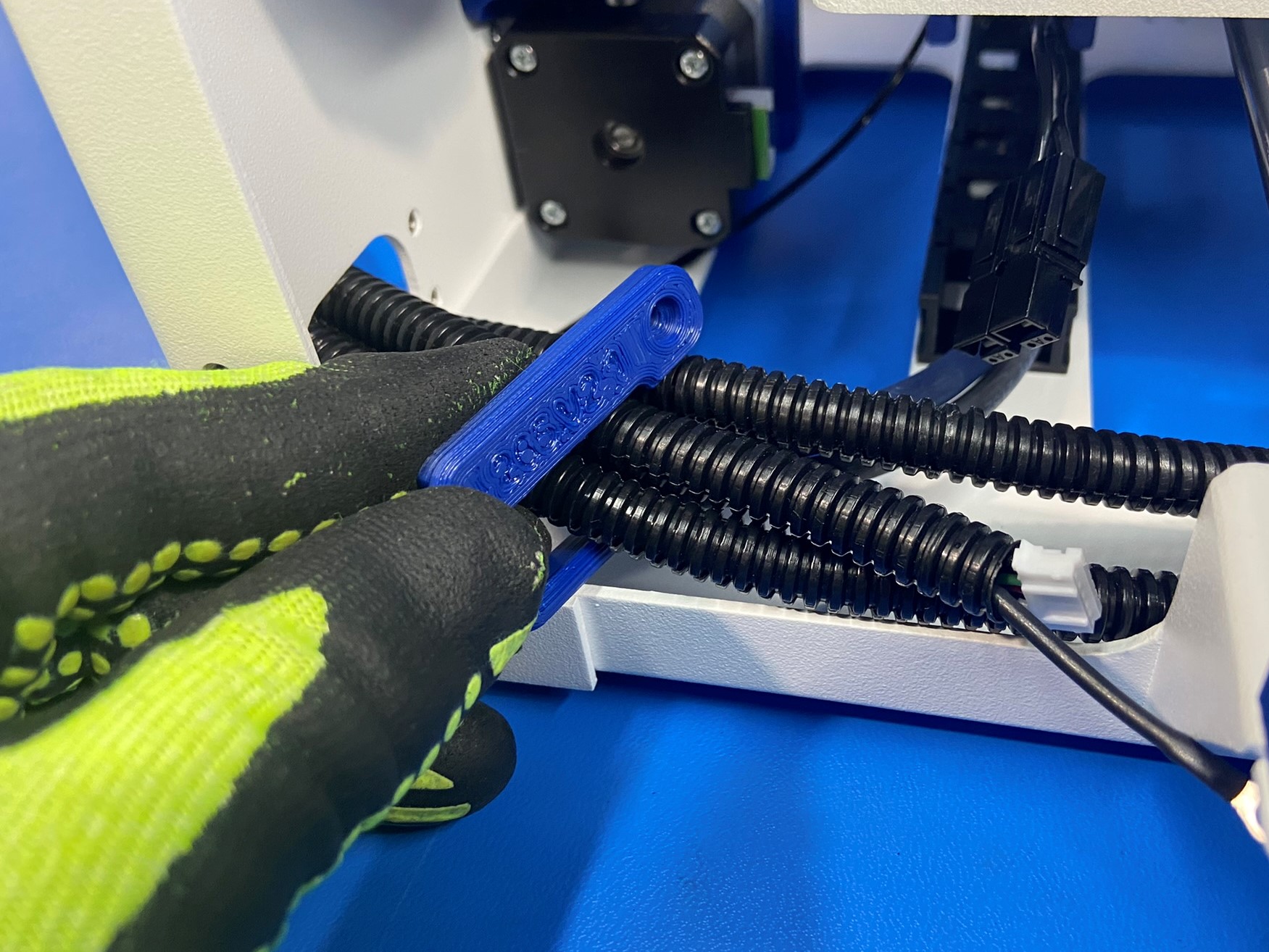
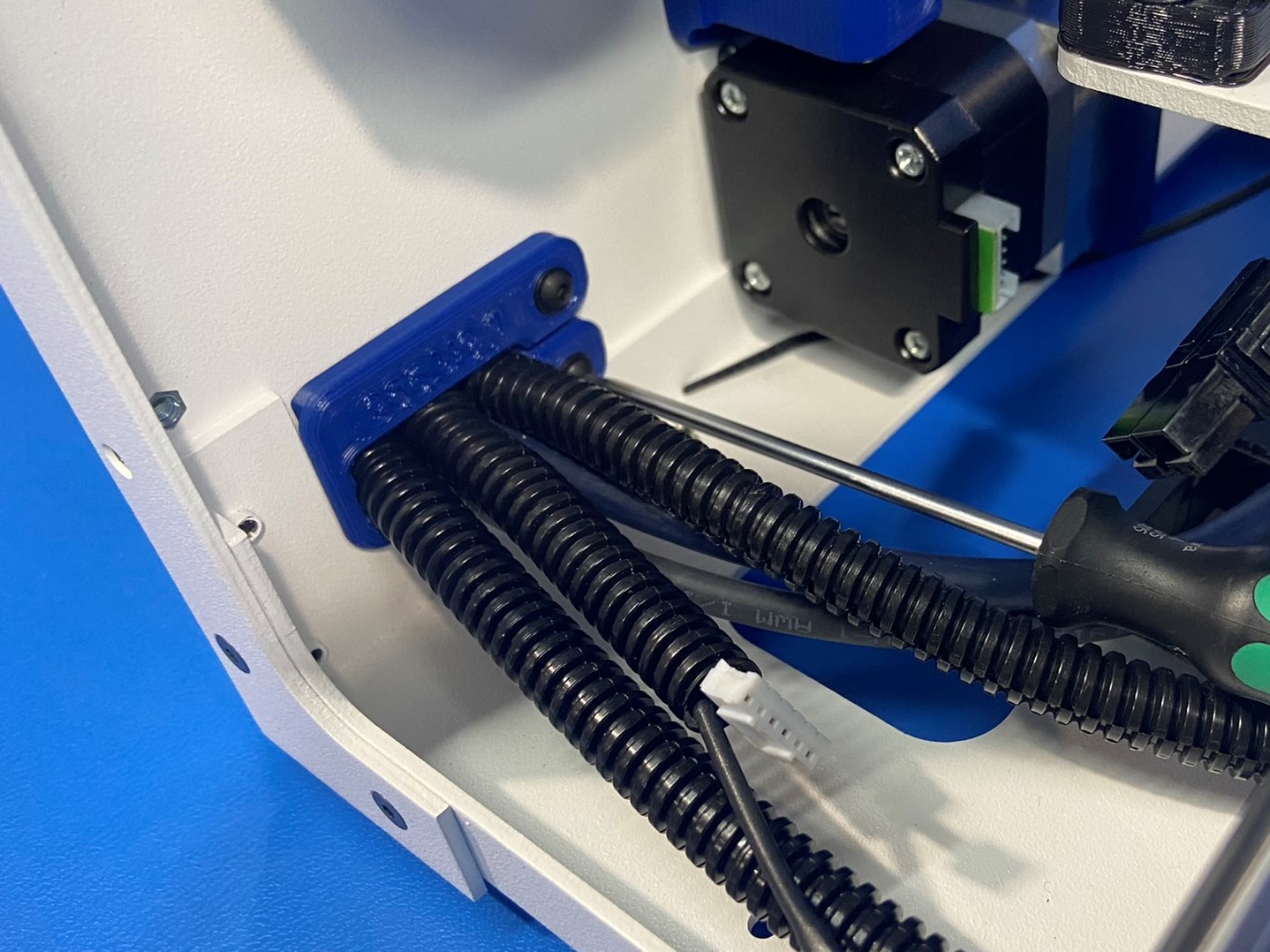
Spread the lower strain relief [PP-GP0265] and slide it over the bed harness wires, once the lower strain relief is seated around the wires make sure it's align with the two holes on the Left Frame Plate.
Secure the lower strain relief with two M3x8 BHCS [HD-BT0137] with M3 washers [HD-WA0038].
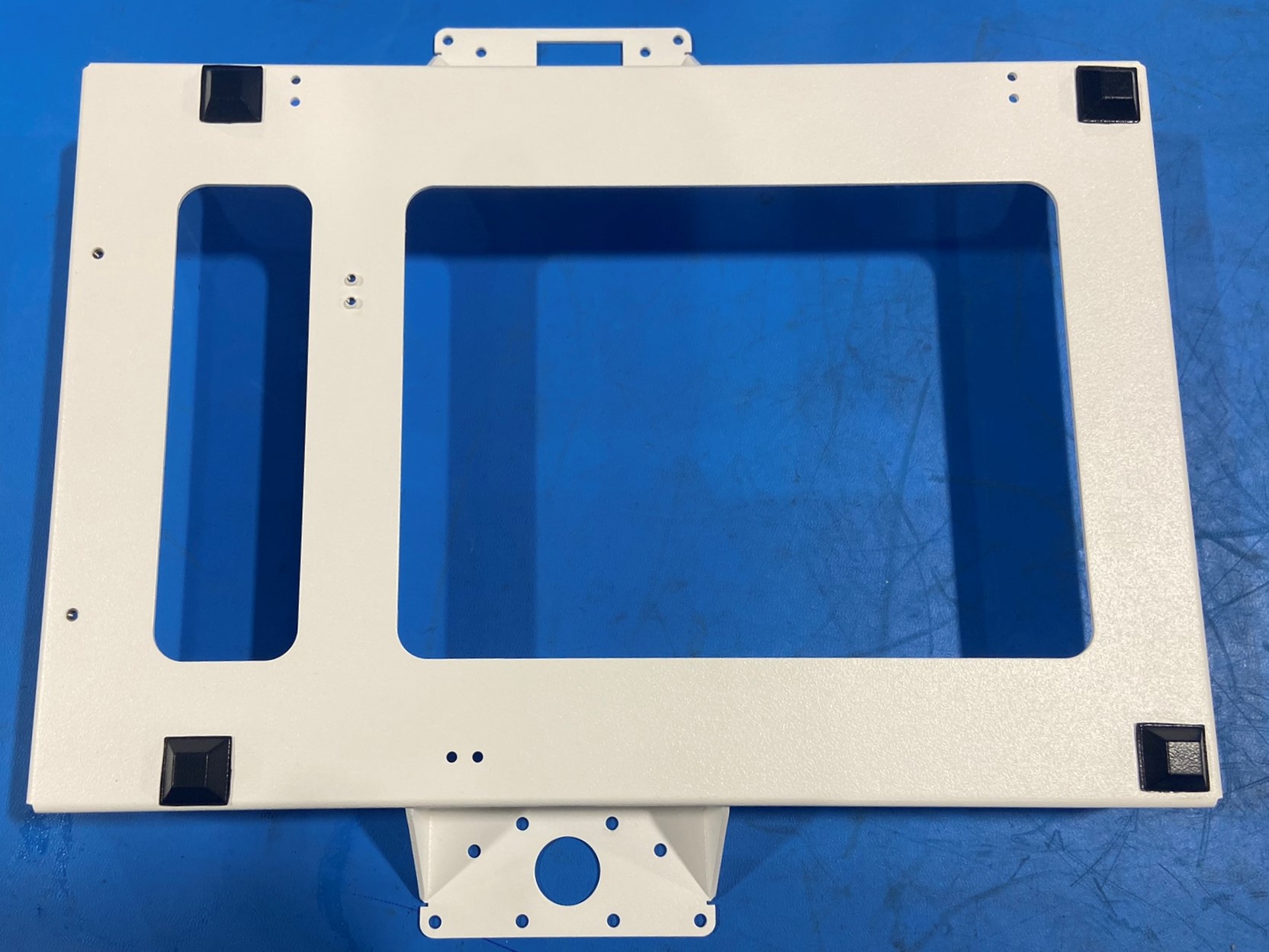
Flip the printer onto the top frame
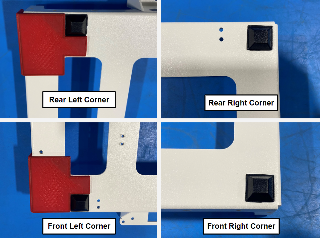
Place 2x rubber bumper squares [HD-MS0054] in the two corners on the right side of the printer frame.
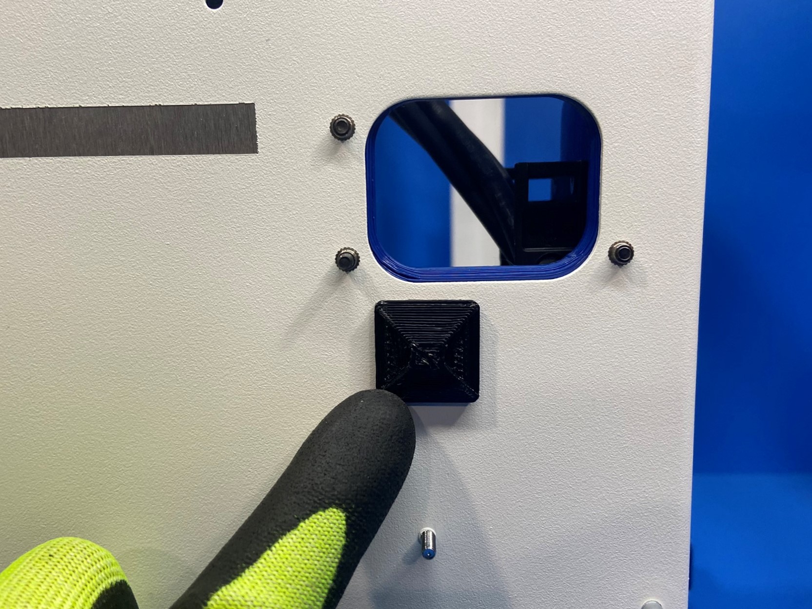
Place 2x rubber bumper squares [HD-MS0054] in the two corners of the left frame side. The squares need to be aligned with the cutouts in the printed jig. See [reference#1]
Remove the backing of one adhesive pad [HD-MS0571] and firmly press it onto 1x universal cable tie holder [PP-GP0483]. Repeat this step with the second pad
Install one cable tie holder onto the left plate just below the upper strain relief as pictured.
Install the second cable tie holder just under the bottom left board mounting standoff as pictured.