Open HardwareAssembly Instructions
Guides for installation and assembly of the LulzBot line of products made by FAME 3D LLC.
Guides for installation and assembly of the LulzBot line of products made by FAME 3D LLC.
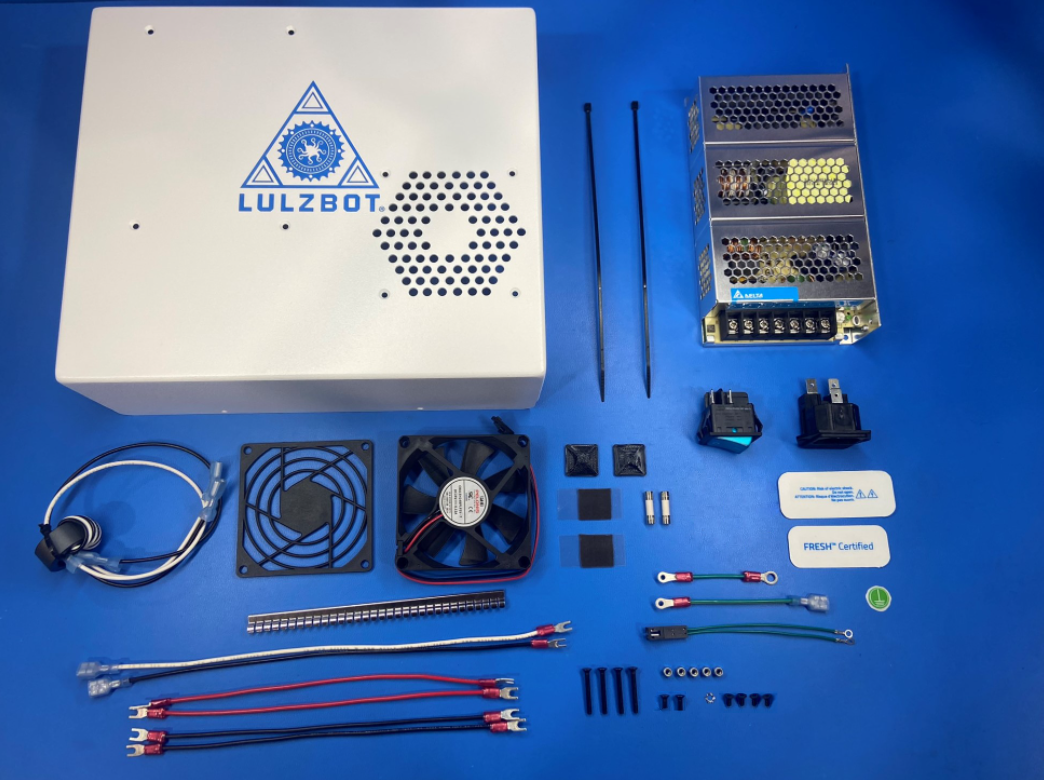
1x- [AS-CB0073] Plug To SW Extension Harness Assembly
2x- [AS-CB0074] PS to EinsyRetro Red Wire
1x- [AS-CB0075] Earth Ground Extension Wire
1x- [AS-CB0076] Switch to PS Extension black
1x- [AS-CB0077] Switch to PS Extension white
1x- [AS-CB0078] Mini 2, Case Fan Harness
1x- [AS-CB0079] Plug to Ground Post Extension
1x- [AS-CB0080] PS to Ground Post Extension
2x- [AS-CB0081] PS to EinsyRetro Black Wire
1x- [DC-LB0153] Electrical Symbol Label
1x- [DC-LB0203] Bio "FRESH" Sticker
1x- [DC-LB0204] Bio Caution Sticker
1x- [EL-HR0109] Finger Guard 80mm Plastic
2x- [EL-MS0414] Cartridge Fuse 250V 3.15A
1x- [EL-MS0432] EMI shielding gasket
1x- [EL-PS0025] 150W 24V Power Supply
1x- [EL-SW0049] Rocker Switch DPST 20A 125V
4x- [HD-BT0128] M3x6 FHCS, Black-Oxide
2x- [HD-BT0130] M3x8 FHCS, Black-Oxide
4x- [HD-BT0206] M3x25 FHCS, Black-Oxide
2x- [HD-MS0571] Adhesive Pad
2x- [HD-MS0058] Wire Tie 8"
5x- [HD-NT0001] M3 Locknut
1x- [HD-WA0035] M3 SST External Serrated Lock Washer
1x- [PP-FP0167] Mini Electronics Case, White
2x- [PP-GP0483] Universal Cable Tie Holder
1x- [PP-MP0028] Power Entry Modules
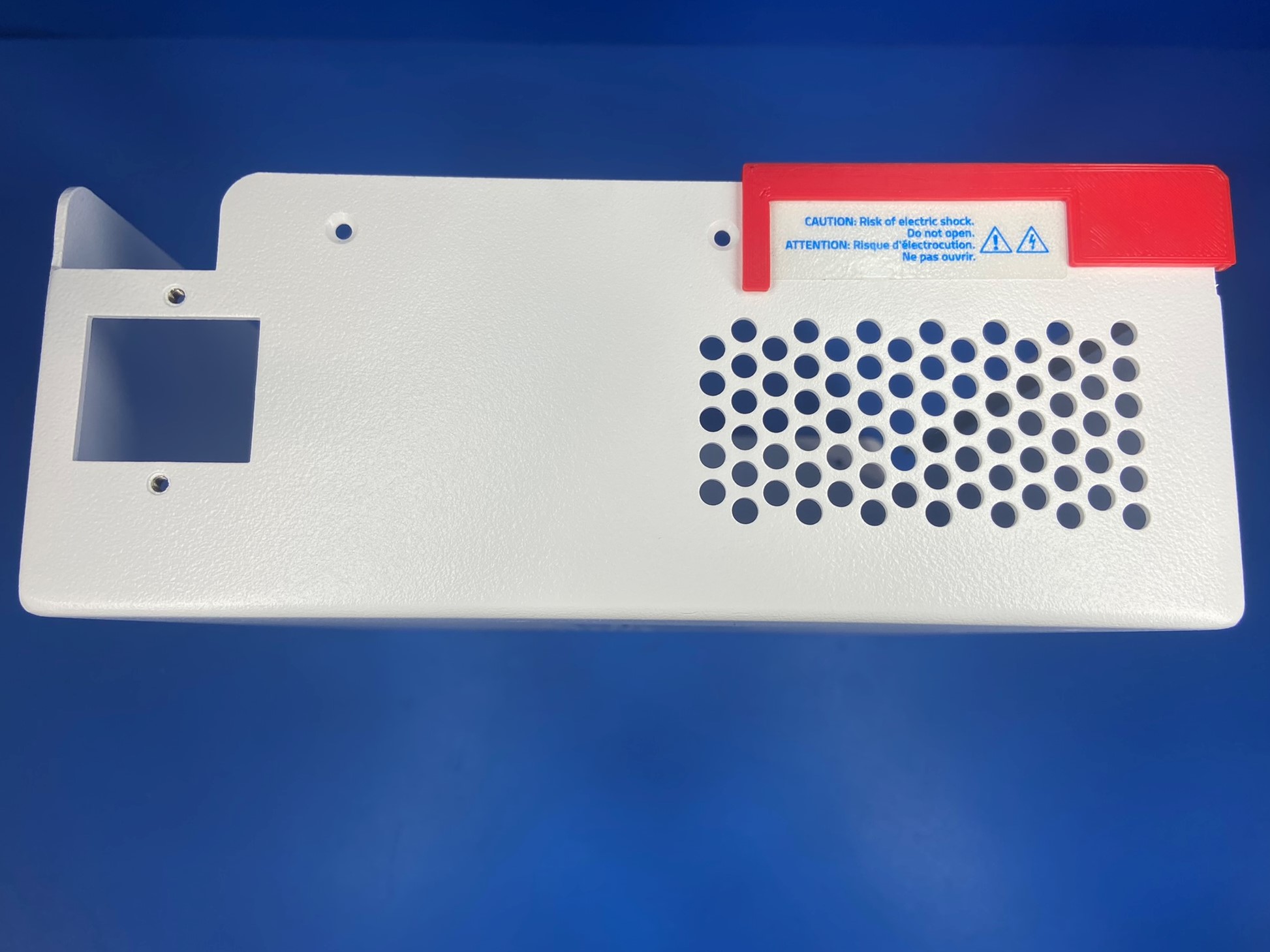
Use the placement jig to place Bio caution sticker [DC-LB0204] on the back side of the electronics case [PP-FP0167]. Be careful with the adhesive side of the sticker, since it's transparent any lint or dust will be seen once it's placed.
Place the Bio "FRESH" sticker [DC-LB0203] on the front side of the electronics case next to the notch on the bottom side. Try to keep the sticker straight when placing it, and try to align it in the middle.
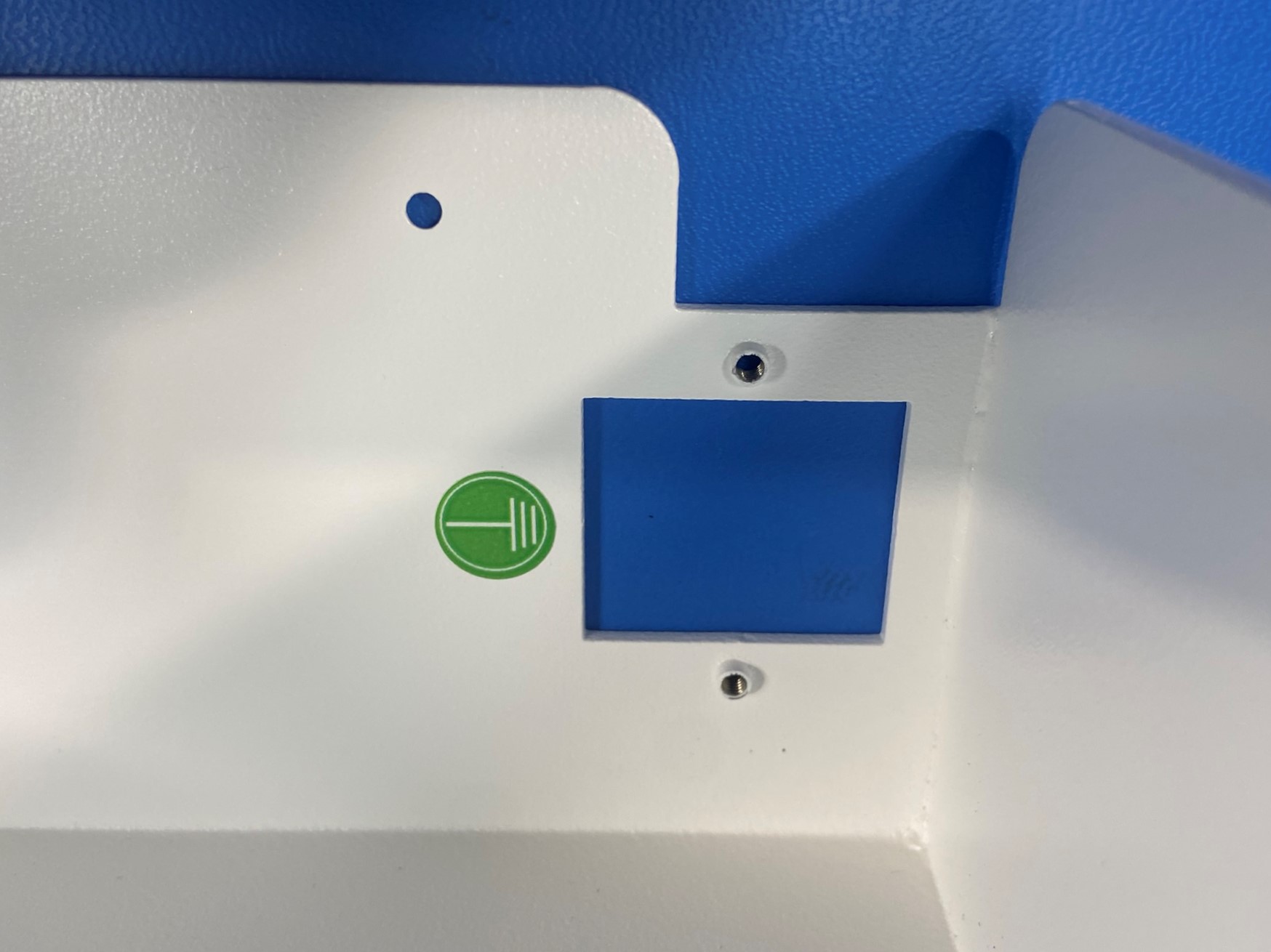
Then place the electrical symbol sticker [DC-LB0153] on the inside of the electronics case on the back wall. Place it on the top of the plug cutout.
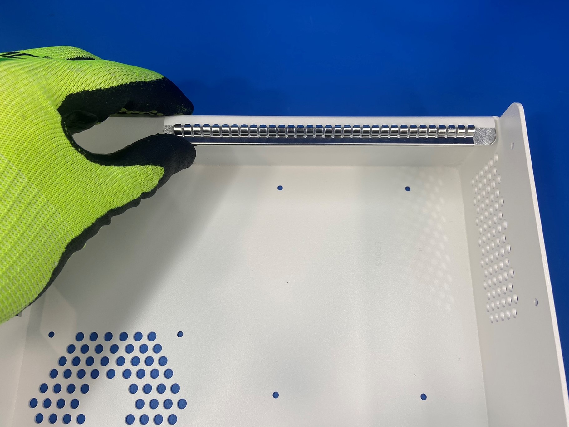
Once all three stickers are placed on the electronics case slide the EMI shielding gasket [EL-MS0432] over the sliver tab on the top side of the electronics case. Make sure the rounded tabs are facing out.

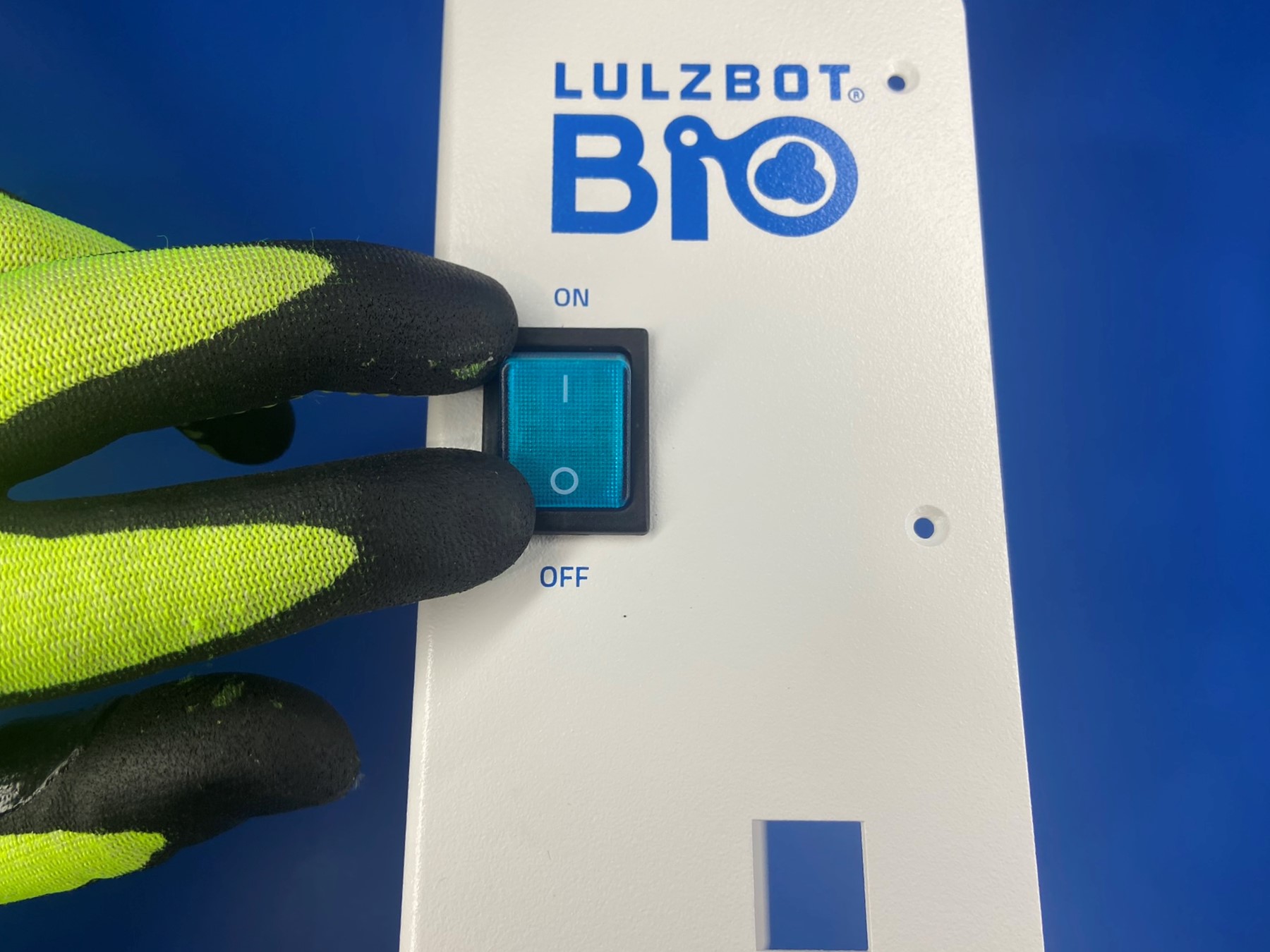
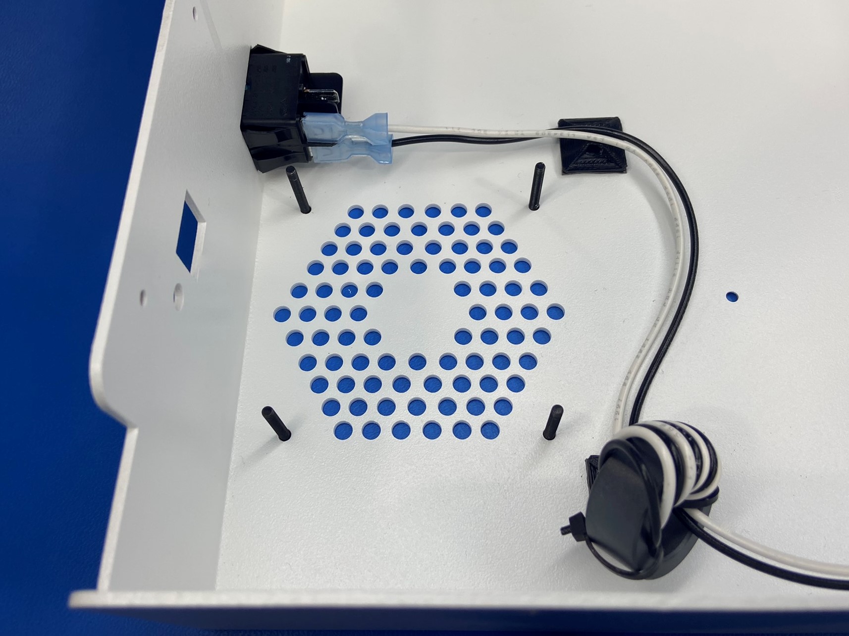
Install the rocker switch [EL-SW0049] on the front side of the electronics case. Make sure the "I" is next to the "ON" and the "O" is next to the "OFF".
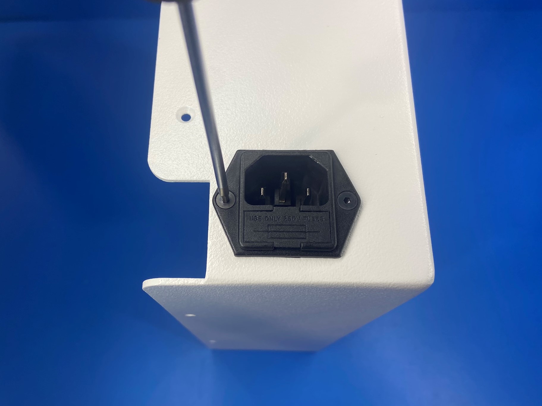
Then using 2x M3x8 FHCS [HD-BT0130] attach the power entry module [PP-MP0028] to the back side of the electronics case.
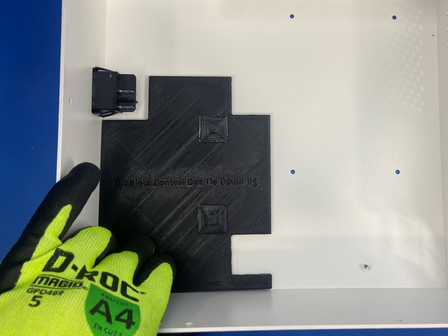
Once the switch and power module are attached to the electronics case place the universal cable tie holder placement jig in the electronics case, make sure the corner with the arrow is in the bottom front corner of the case.
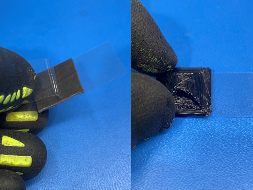
Then remove one of the protective film on the adhesive pad [HD-MS0571] and then stick the universal cable tie holder [PP-GP0483] to the adhesive pad. Repeat this process the other universal cable tie holder.
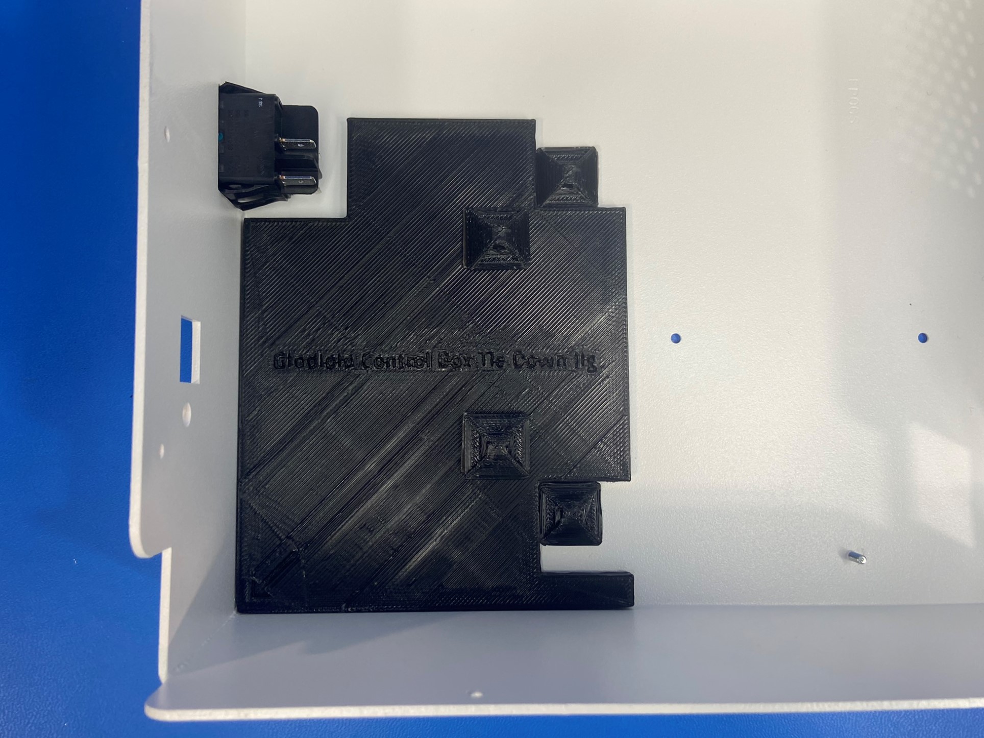
Now remove the other protective film from the adhesive pad and attach the universal cable tie holder to the electronics case, make sure to align the cable tie holder with the cable tie holder that's attached to the jig. Repeat for the other cable tie holder.
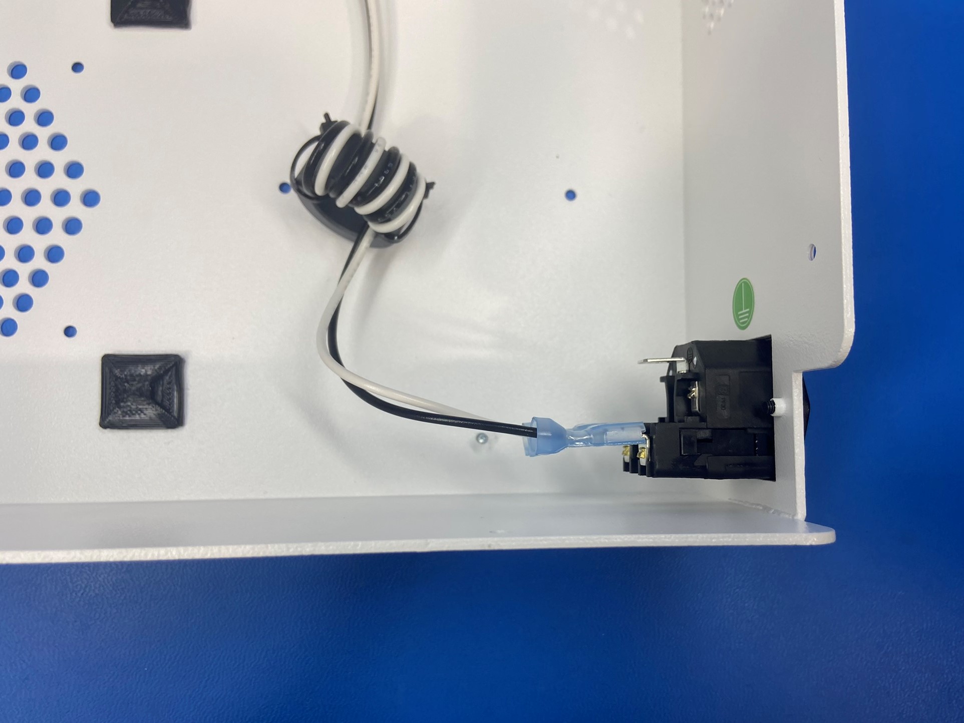
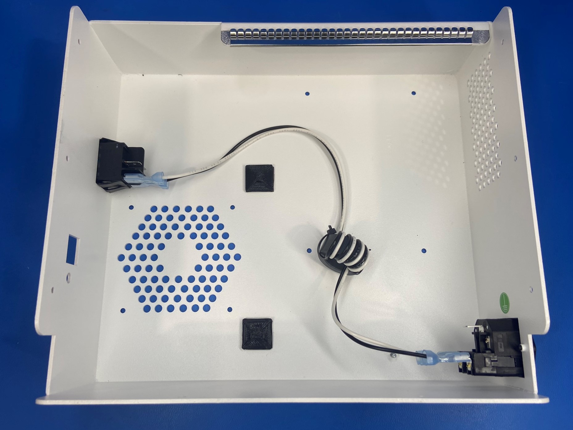
Then take the plug to SW extension harness assembly [AS-CB0073] and connect it to the rocker switch and power entry module. Find the connector that are closer to the ferret (short side) and connect it to the power module. The white wire will be on the bottom tab and black will be on top. Then connect the other end to the rocker switch, the black wire will be connected to the bottom tab and the white wire will connect to the top tab.
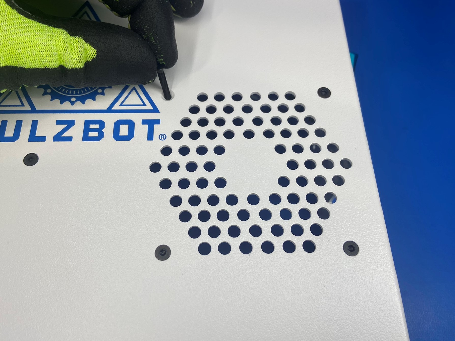
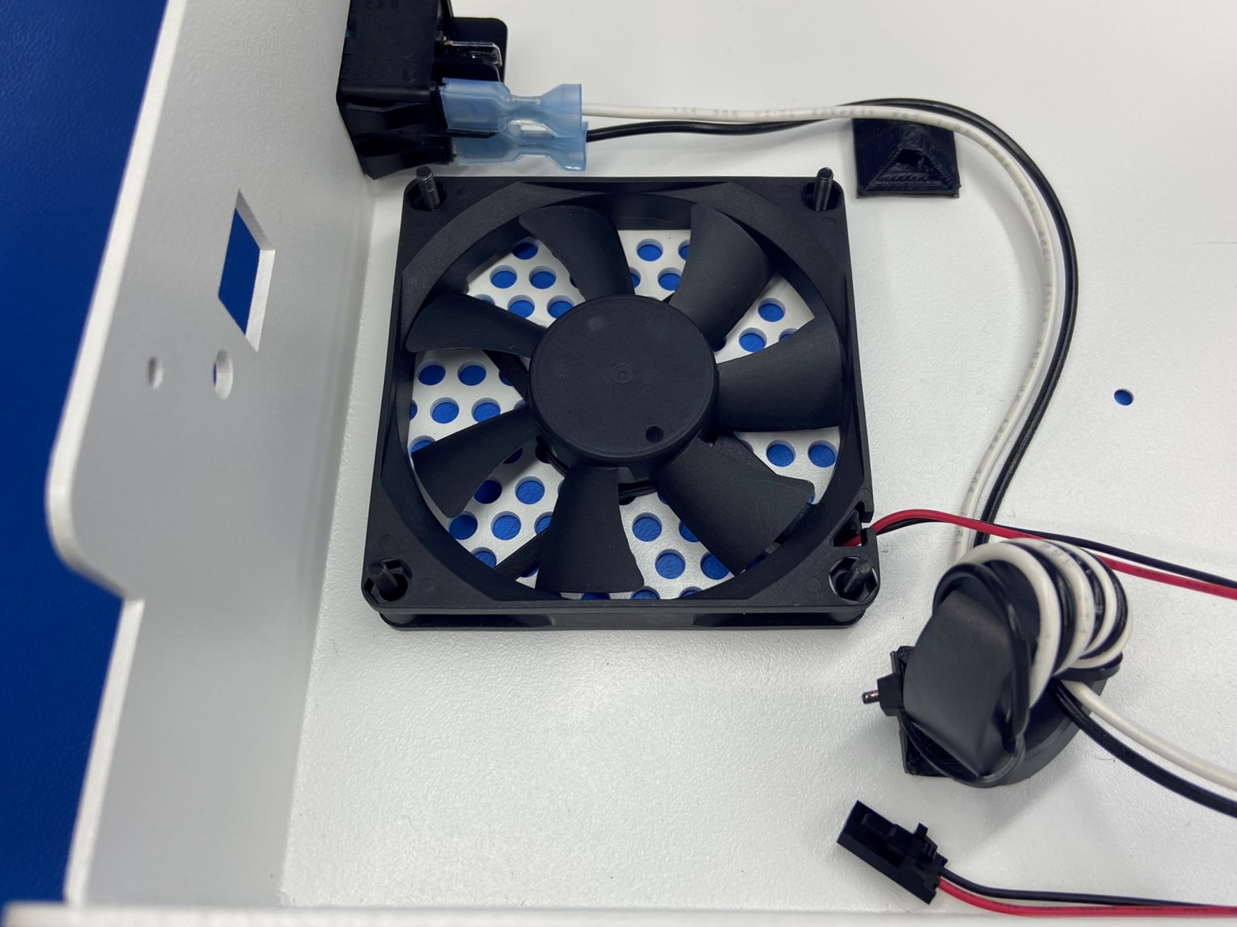
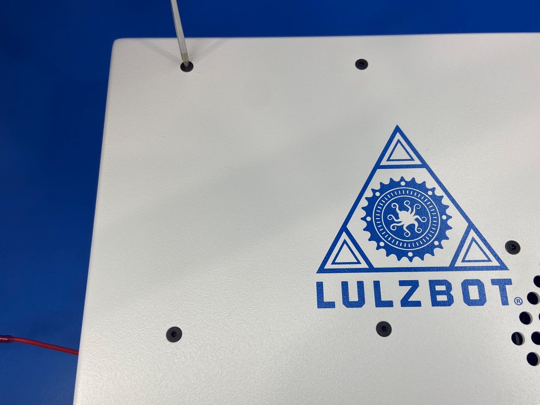
Flip the electronics case over so that the LULZBOT logo is facing up and slide 4x M3x25 FHCS [HD-BT0206] through the four holes next to the holes that make a hexagon.
While holding the screws in place flip the electronics case back over, so that the screws make four posts. Now take the case fan harness [AS-CB0078] and slide it onto the four screw making sure the side with the sticker is against the electronics case. The wires should also be located in the bottom right corner.
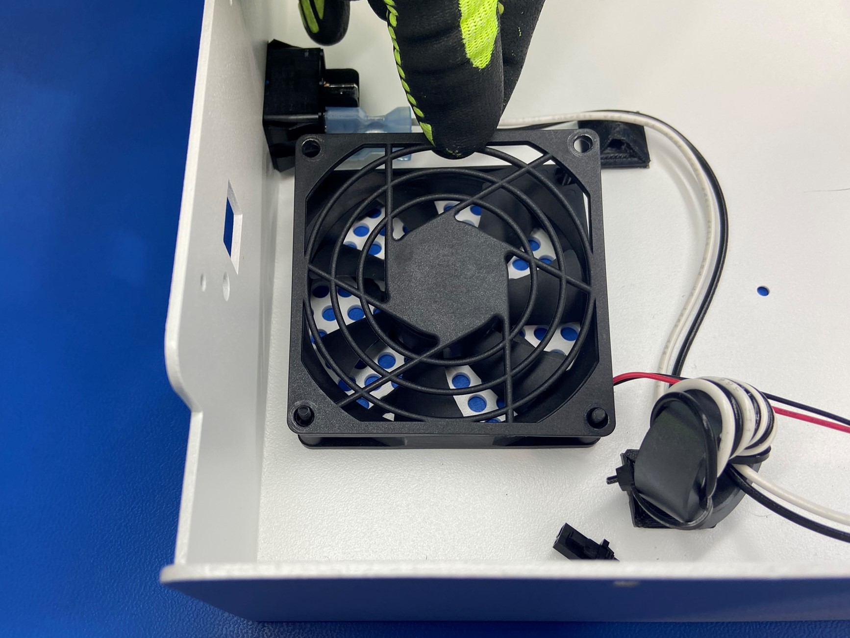
Then look for the side of the finger guard [EL-HR0109] that says "THIS SIDE TO FAN" and with that side down slide it over the four screws.
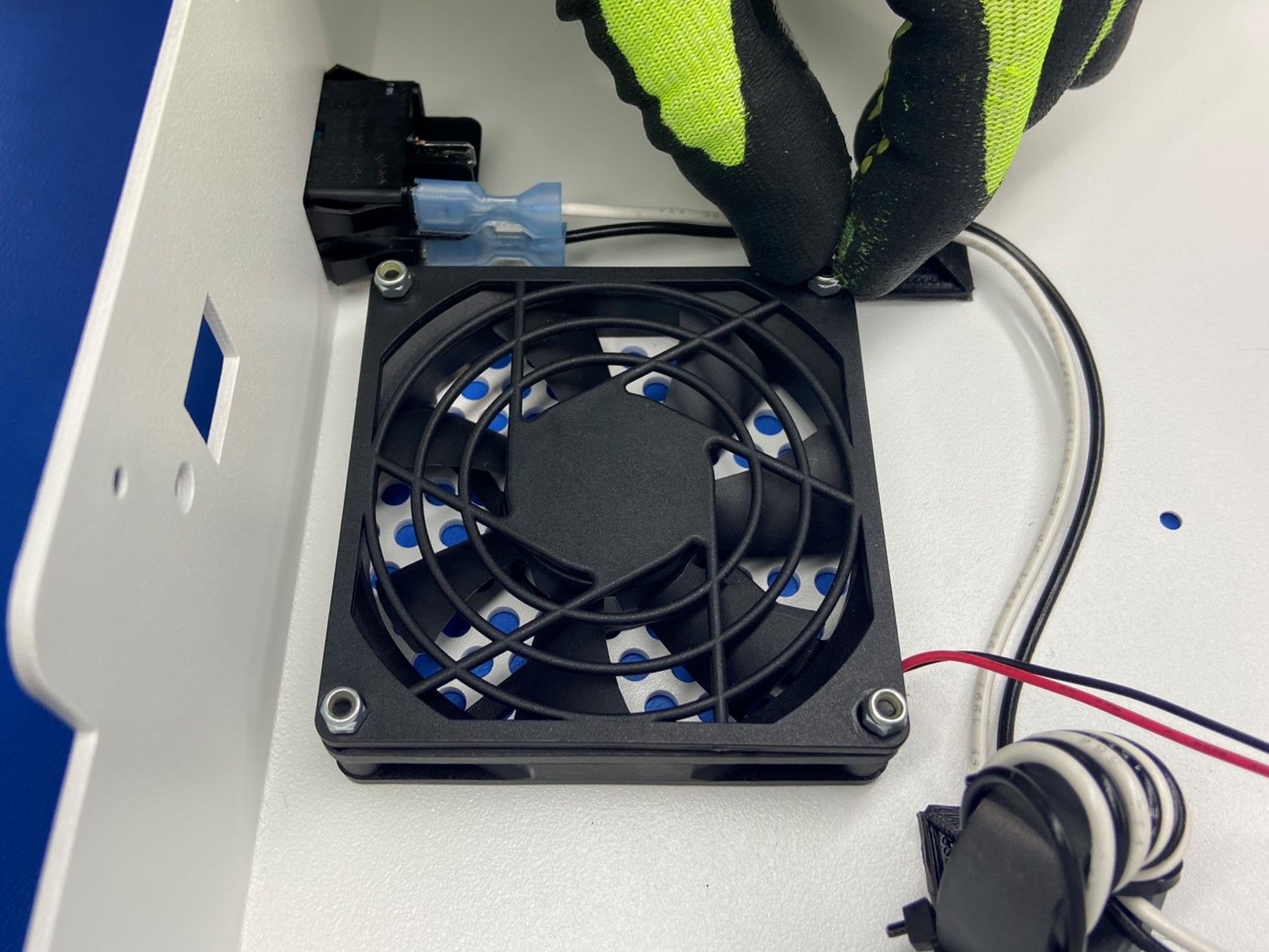
Once the case fan harness and finger guard are in place thread 4x M3 locknuts [HD-NT0001] onto the screws.
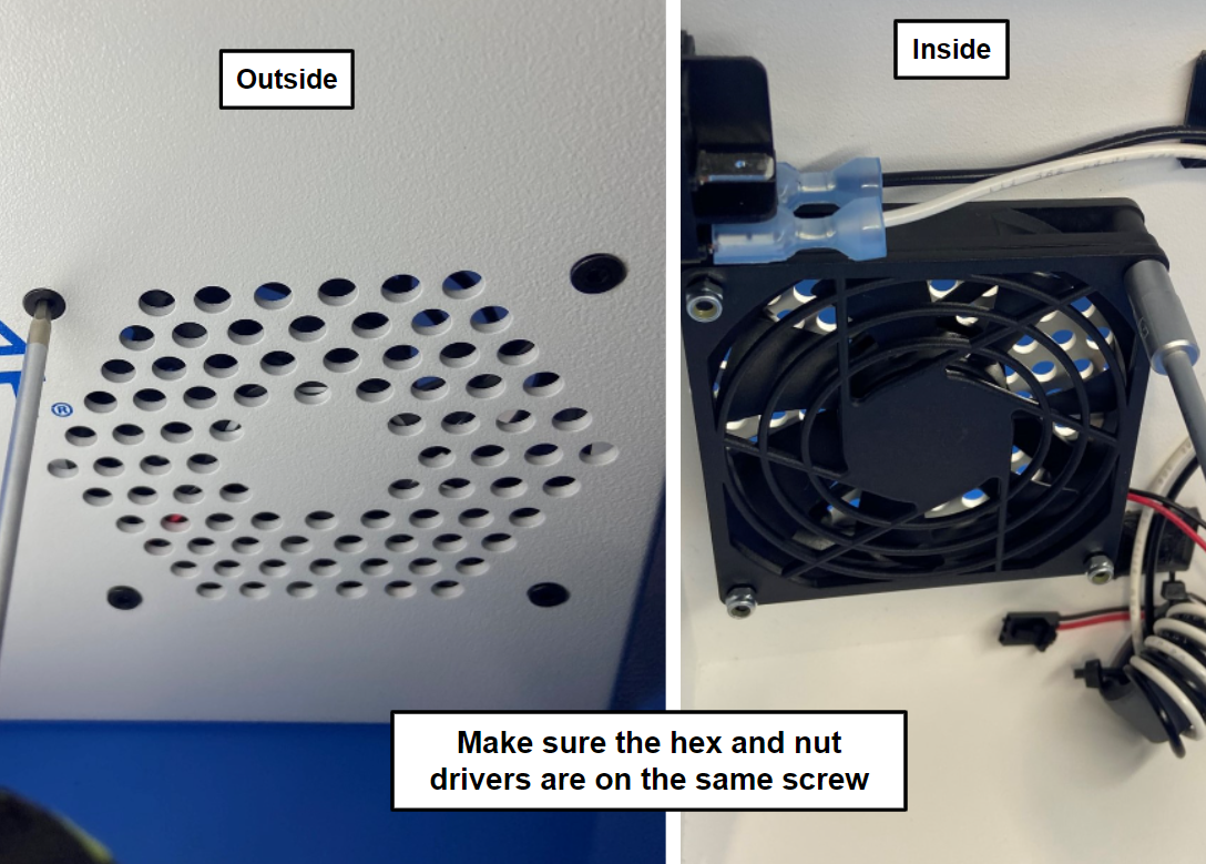
Now flip the electronics case on its bottom side so that you can access the inside and outside of the case. Using a 2mm hex driver and a M3 nut driver secure the fan to the electronics case.
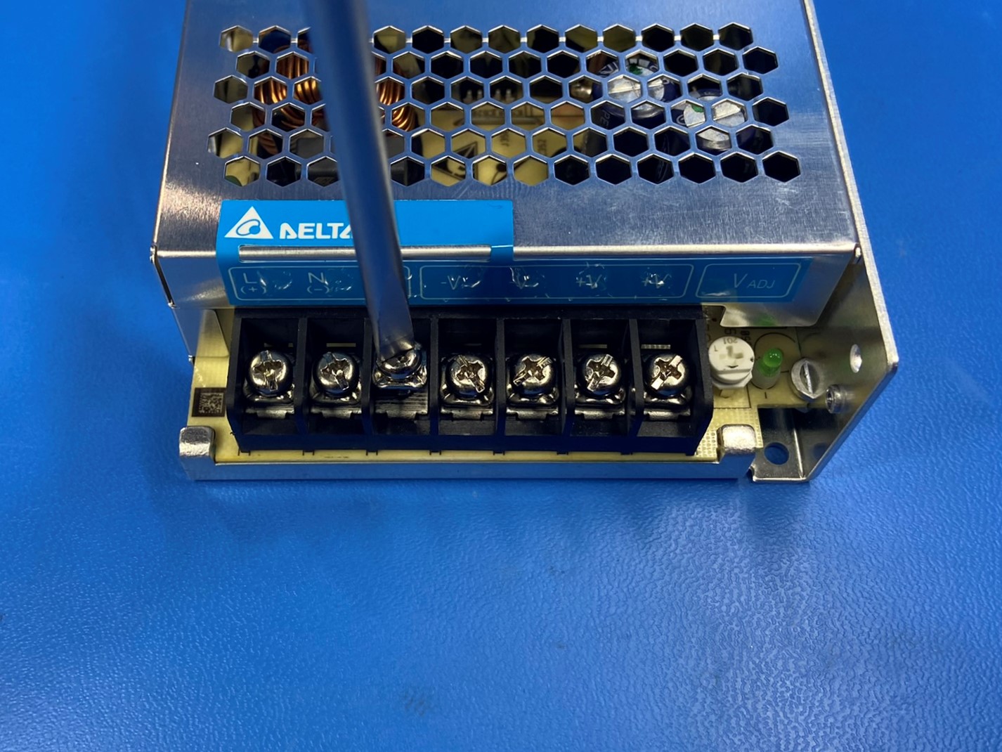
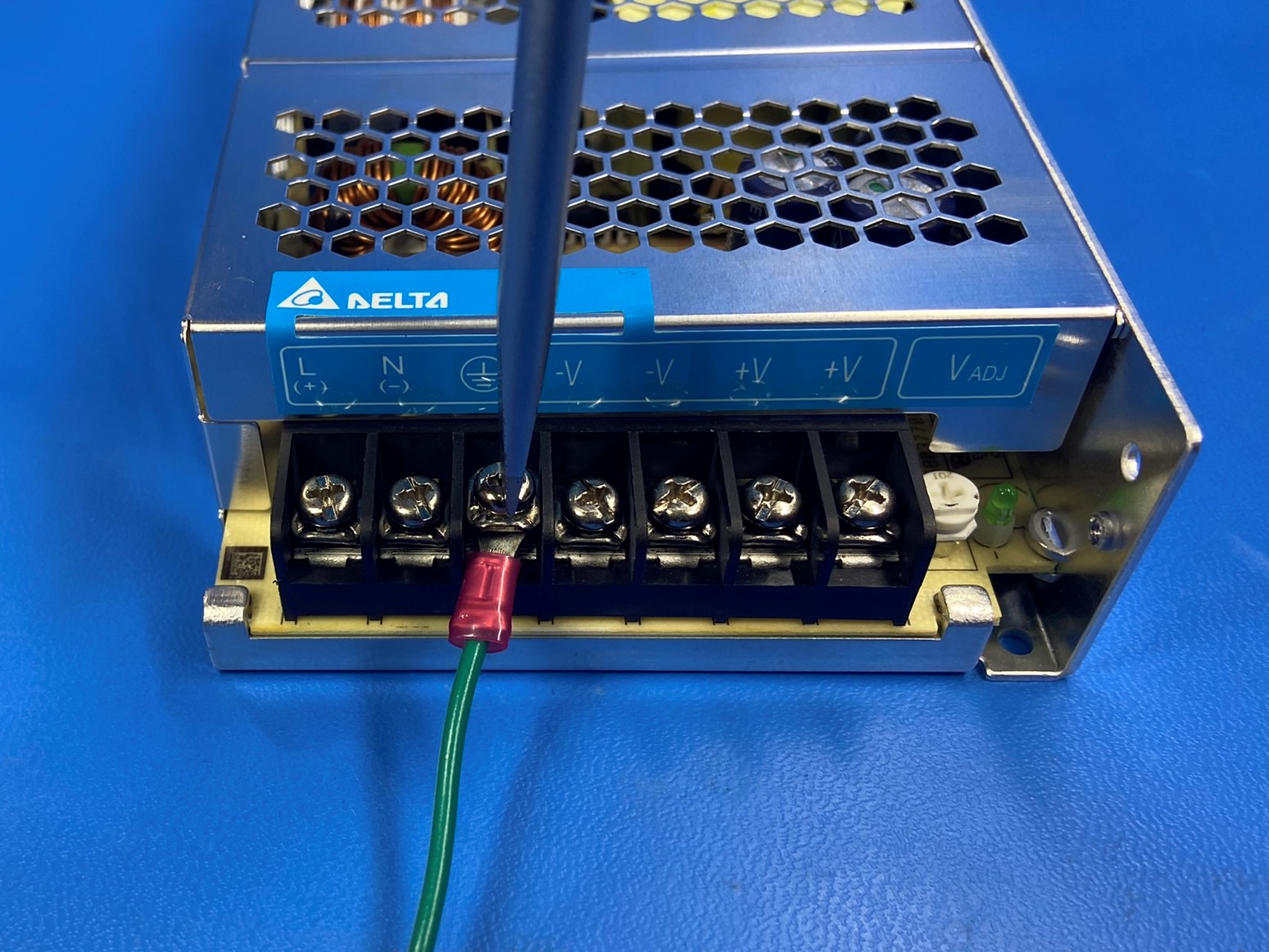
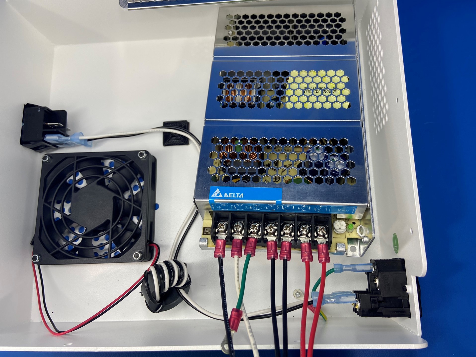
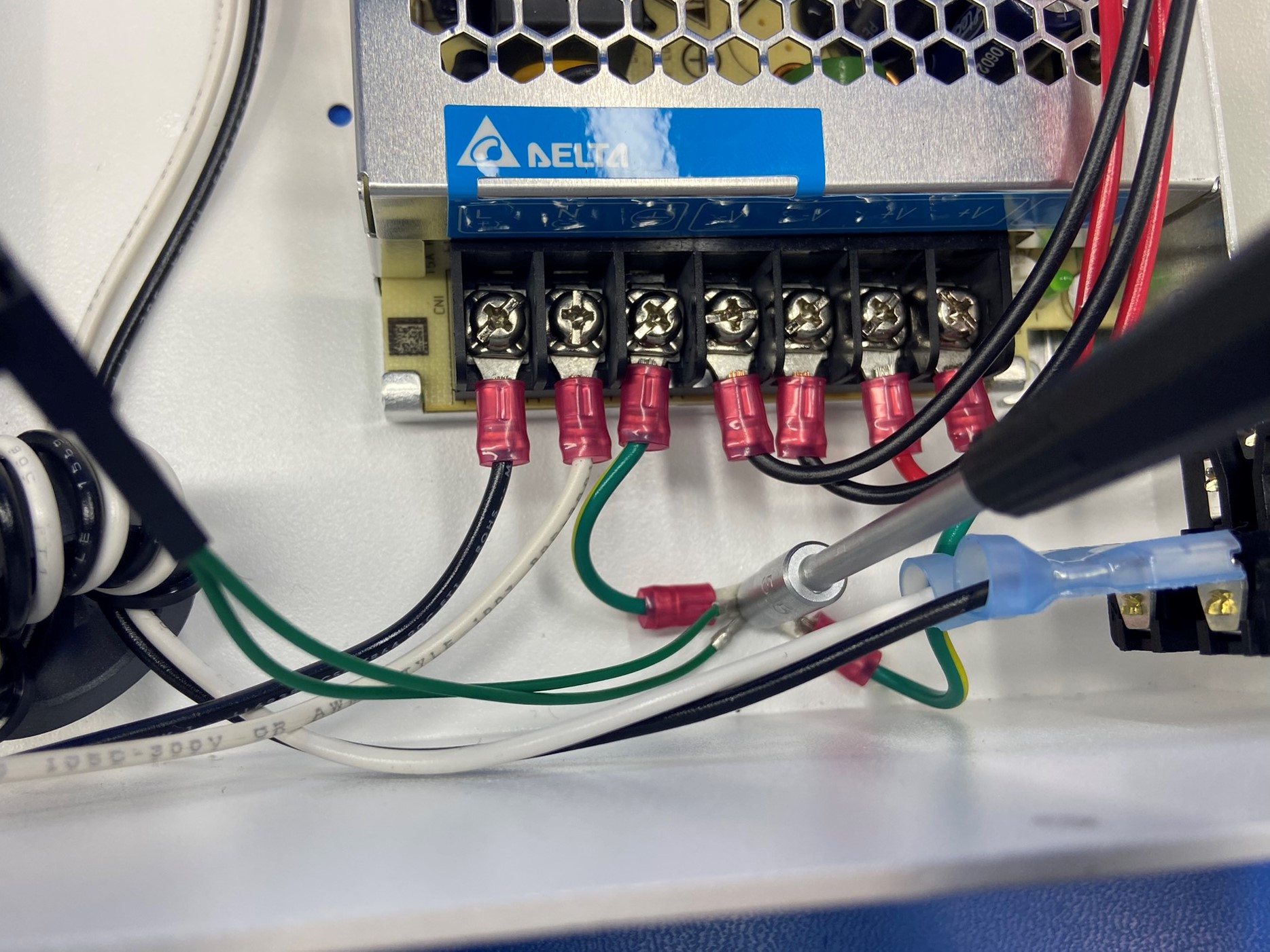
Prepare the 150W 24V power supply [EL-PS0025] for the electronics case. Start by removing the ground screw (third from the left) and slide the PS to ground post extension [AS-CB0080] around the screw. Then replace the screw in the block terminal.
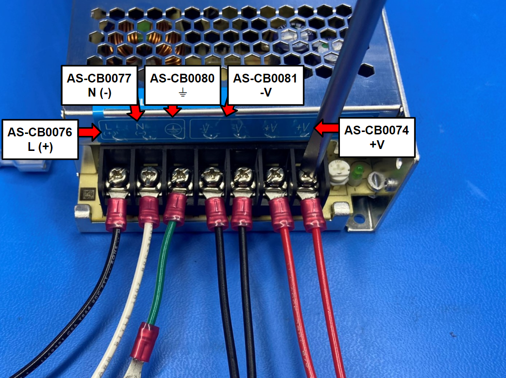
Now loosen the two screws on the left side of the ground screw. Slide the switch to PS extension black [AS-CB0076] under the first screw followed by the switch to PS extension white [AS-CB0077] between the black wire and the green wire.
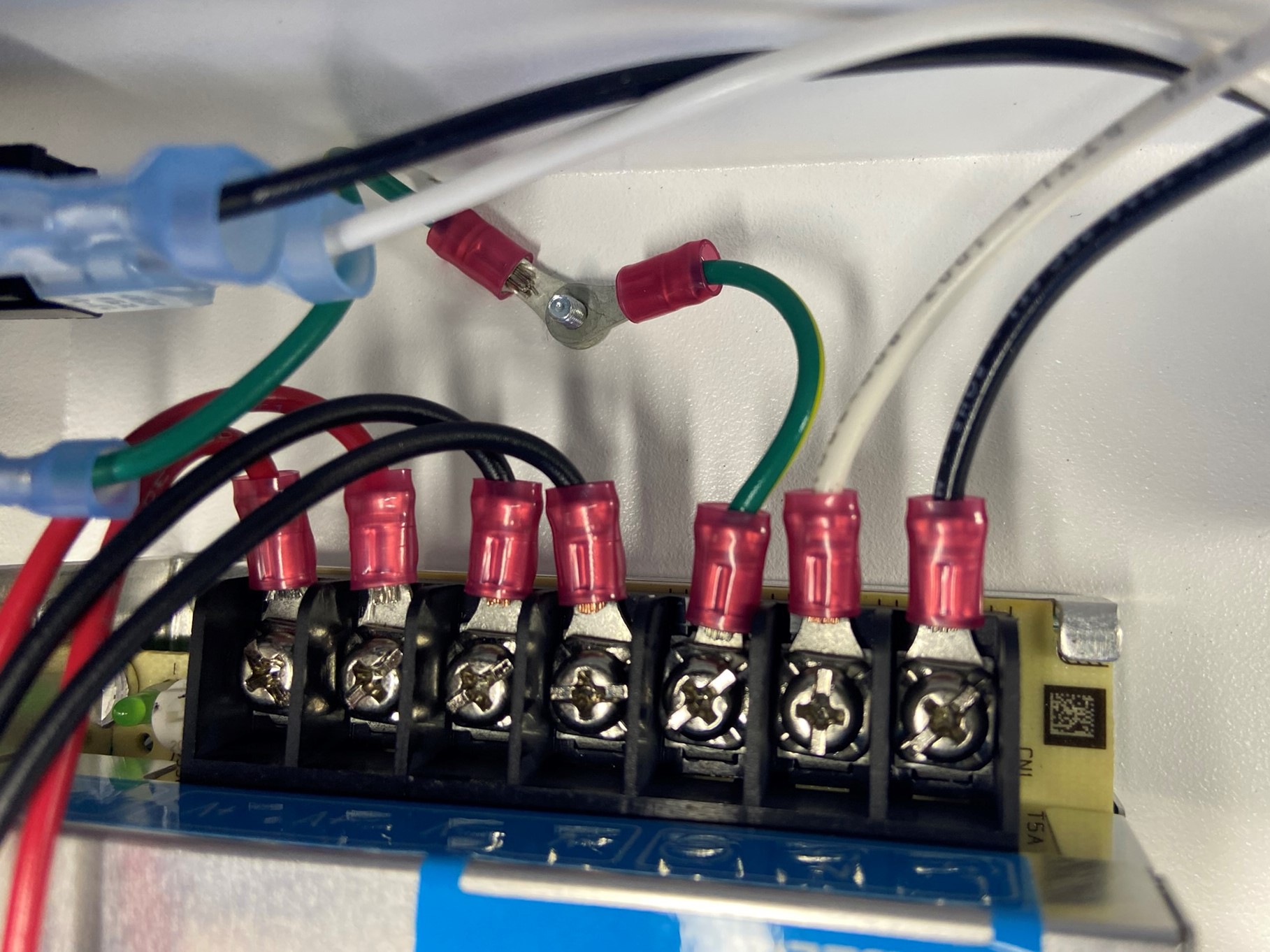
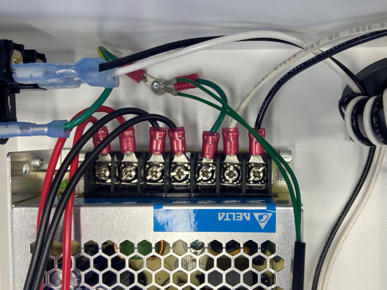
Now loosen the other four screws on the right side of the ground screw, place 2x PS to EinsyRetro black wires [AS-CB0081] under the [-V] and two PS to EinsyRetro red wires [AS-CB0074] under the [+V]. Tighten all the screws and tug on wires to verify that they are secured to the power supply.
[AS-CB0076] goes under "L (+)"
[AS-CB0077] goes under "N (-)"
[AS-CB0080] goes under "⏚"
[AS-CB0081] goes under both "-V"
[AS-CB0074] goes under both "+V"
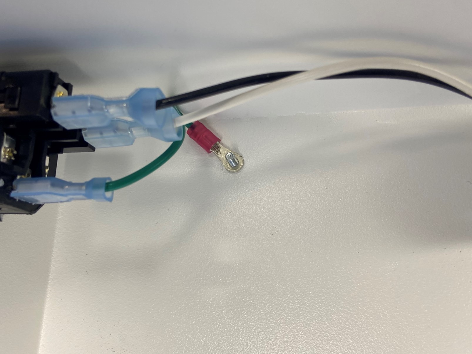
Place a M3 SST external serrated lock washers [HD-WA0035] around the ground post. Take the green ground wire that connected to the power entry module and slide it around the ground post.
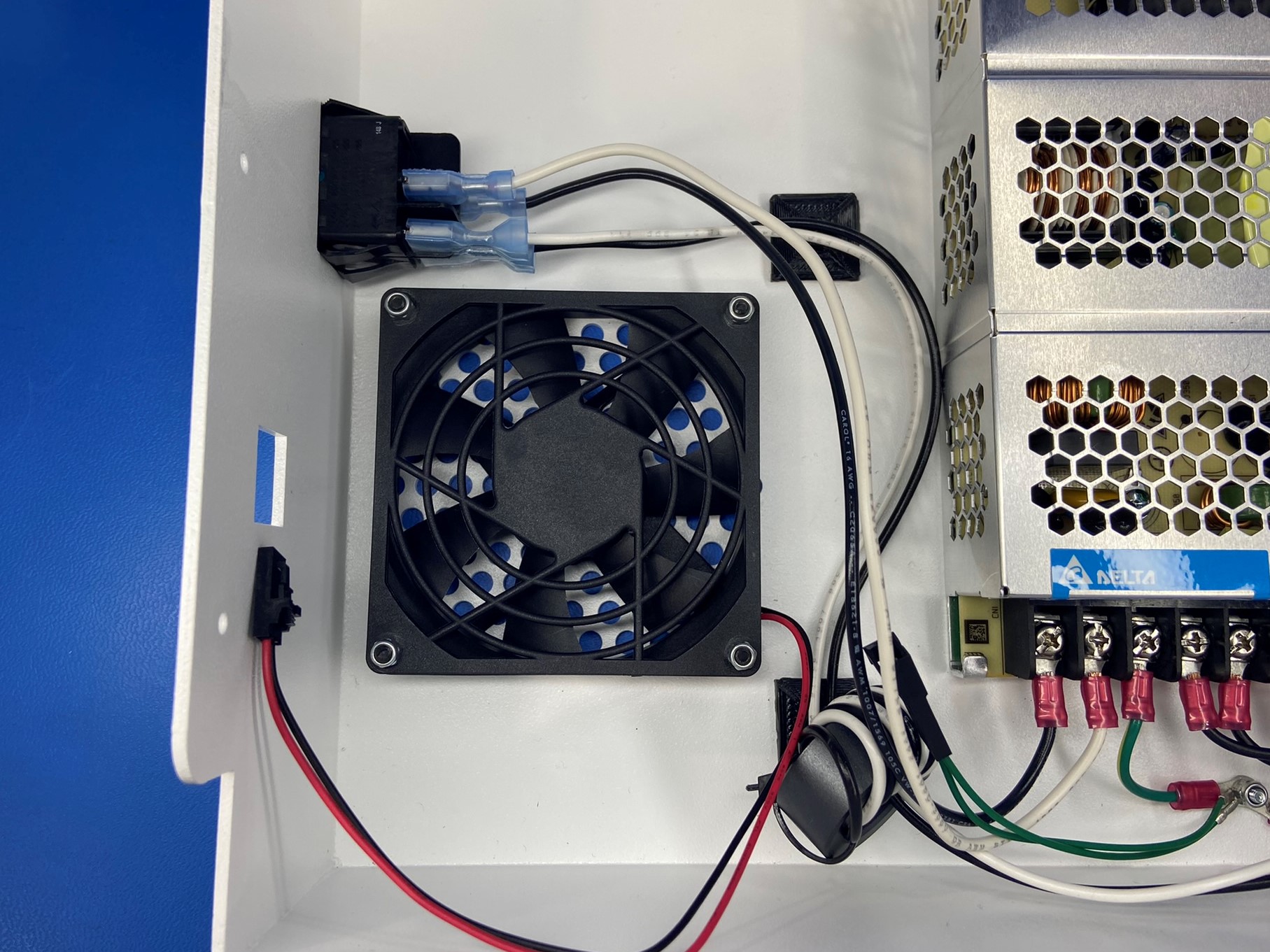
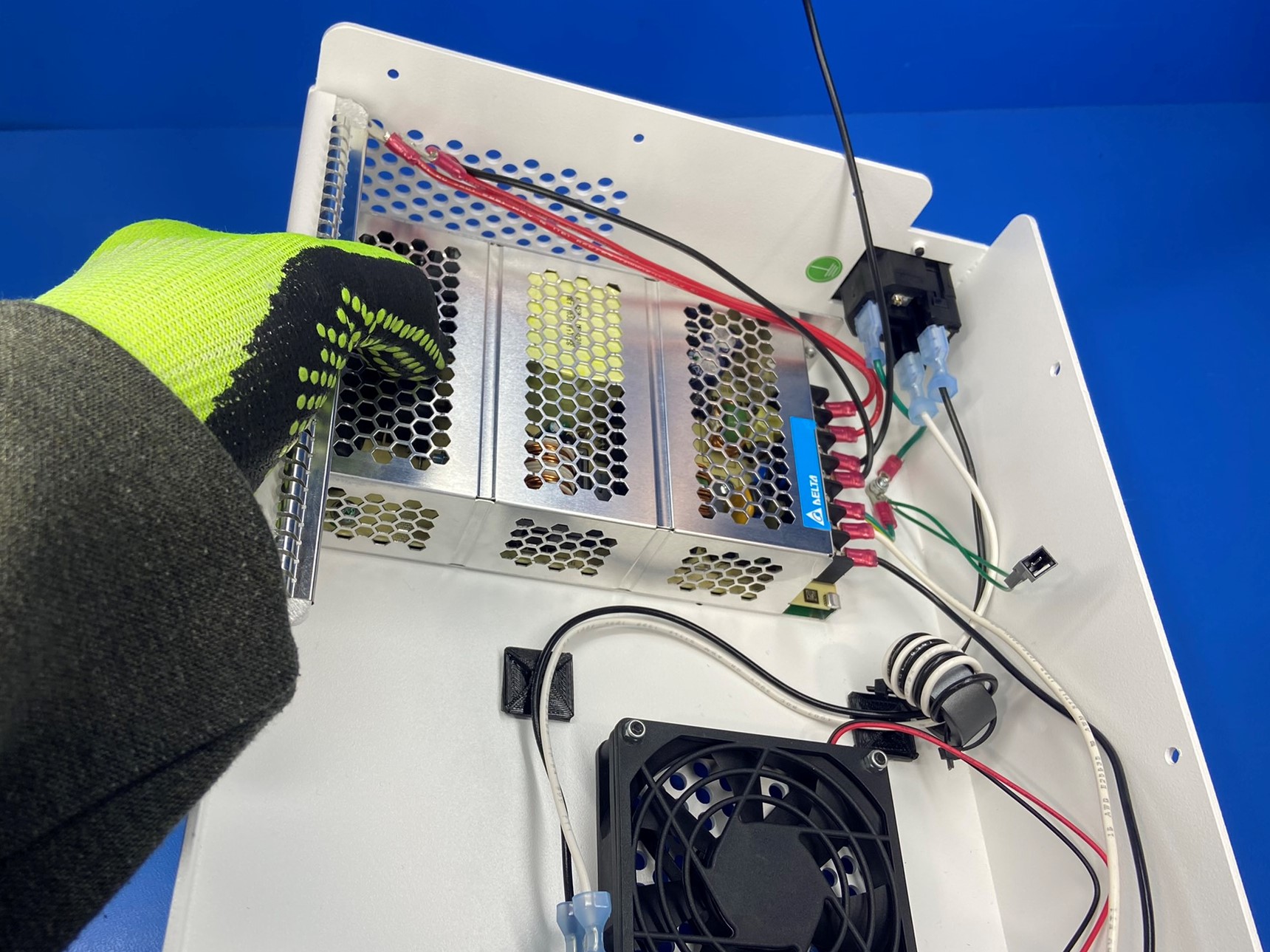
Then place the power supply inside the electronics case with the wires close to the power entry module.
Find the green ground wire that is connected to the power supply and slide it around the ground post. Followed by the earth ground extension wire [AS-CB0075] make sure both connectors are around the ground post. Then thread a M3 locknut [HD-NT0001] and tighten.
Hold the power supply in place and carefully flip the electronics case over so that LULZBOT logo is facing up. Then using 4x M3x6 FHCS [HD-BT0128] secure the power supply to the electronics case.

Connect the white [AS-CB0077] and black [AS-CB0076] wires that are connected to the power supply to the rocker switch. The black wire will connect to the bottom tab and the white wire will connect to the top tab.
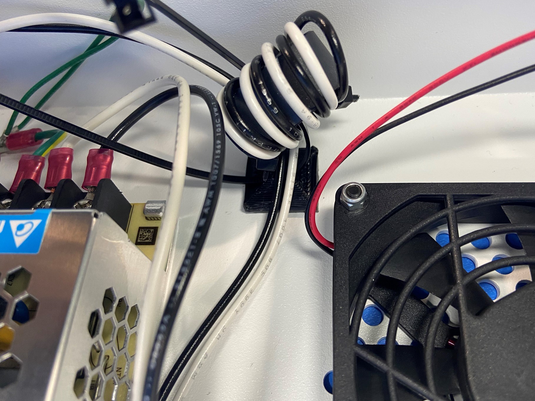
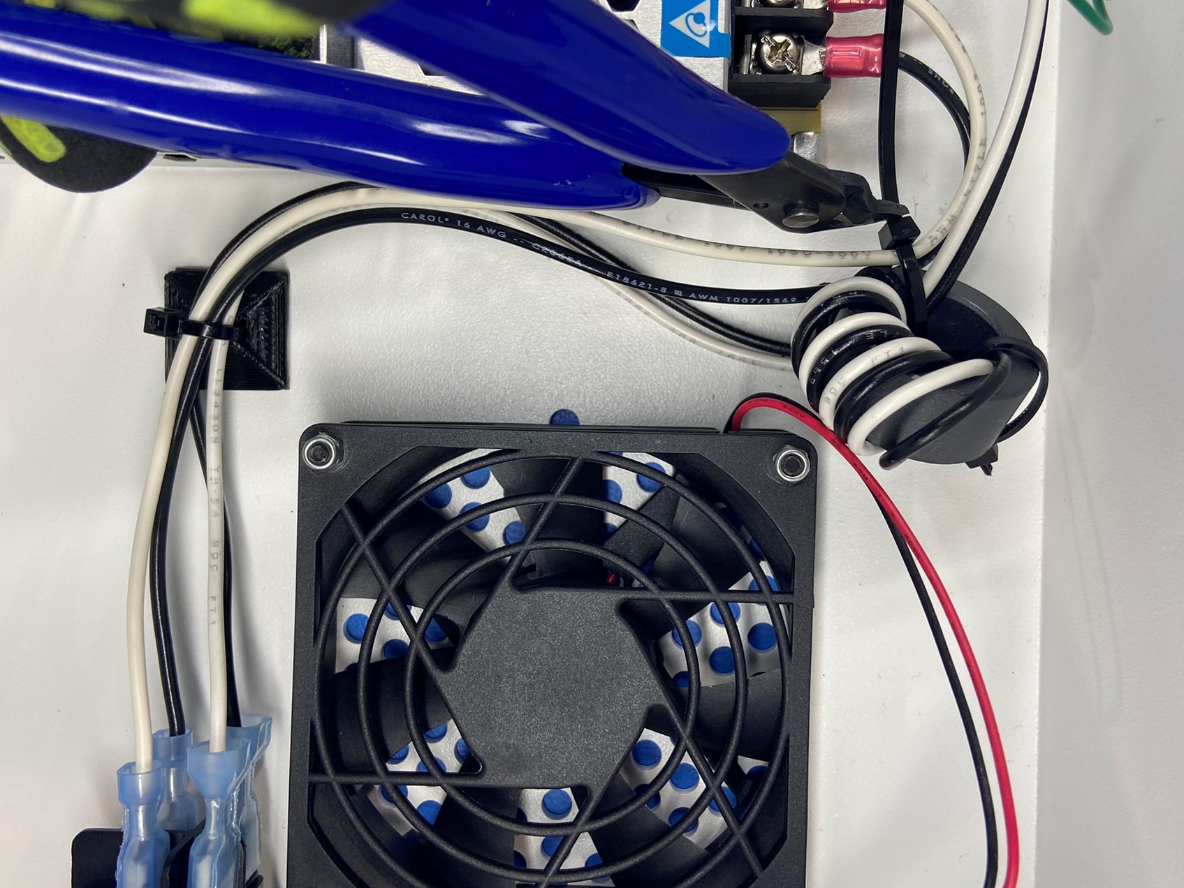
Then using 2x wire ties [HD-MS0058] secure the four switch wires to the two universal cable tie holders.
Use one of the wire ties for the top cable tie holder making sure to secure all four wires.
Then use the second wire tie for the bottom cable tie holder, make sure to secure all four wires along with the metal ferrite. Tighten and trim both wire ties.