Open HardwareAssembly Instructions
Guides for installation and assembly of the LulzBot line of products made by FAME 3D LLC.
Guides for installation and assembly of the LulzBot line of products made by FAME 3D LLC.
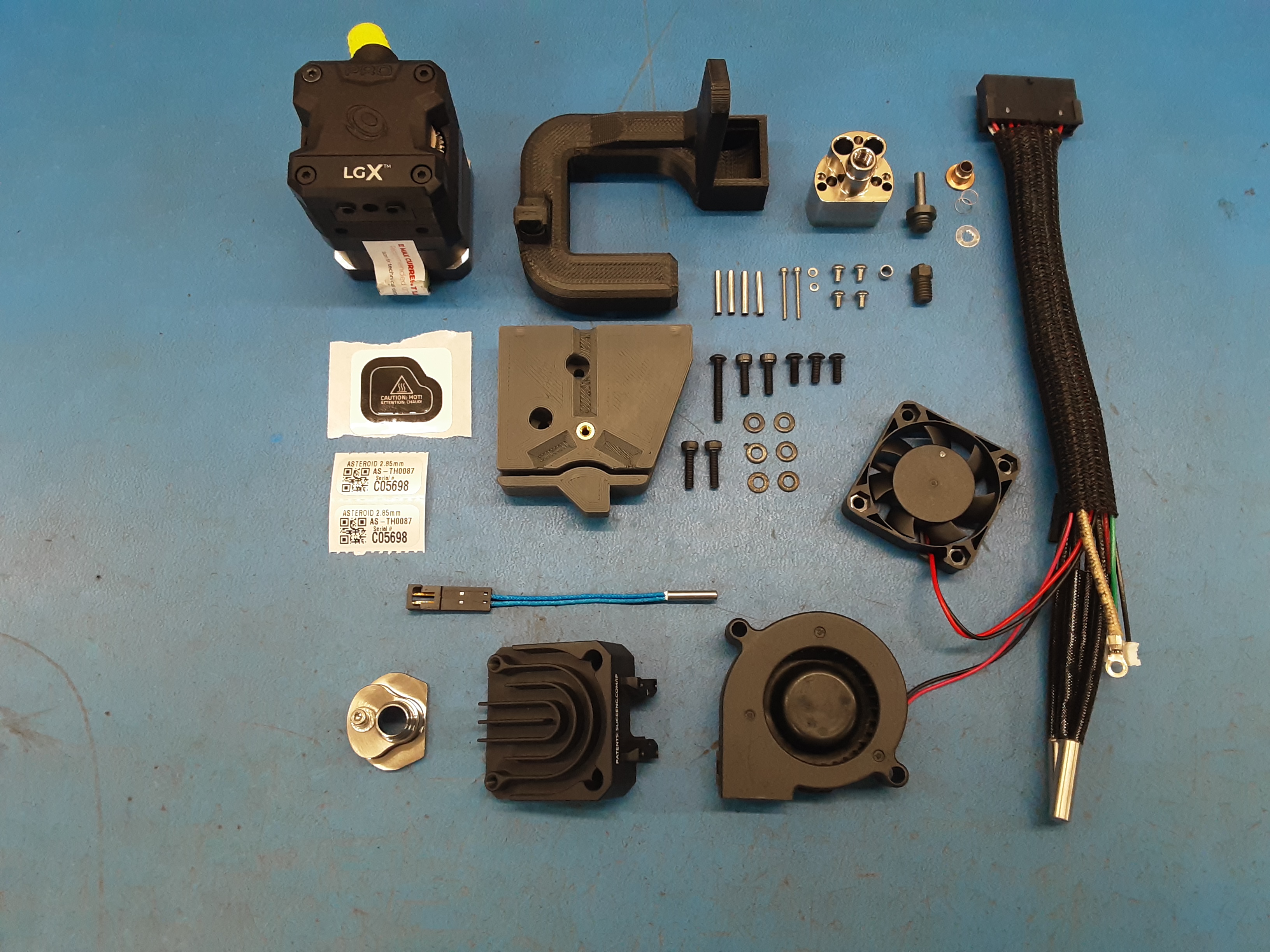
1x [AS-CB0208] Asteroid Wire Harness
1x [DC-LB0154] Caution Hot Sticker
2x [DC-LB0160] Tool Head Serial Number Sticker, Matte Silver, 1" x 0.5", Thermal
1x [EL-TH0012] E3D Cartridge Style Thermistor w/ Molex Connector
2x [HD-BT0005] M3 x 10 Bolt, SHCS Black-Oxide
2x [HD-BT0039] Metric Class 12.9 SHCS Alloy Steel, M3 x 12mm Length, 0.50mm Pitch
3x [HD-BT0137] M3 x 8 Bolt, BHCS, Black Oxide
1x [HD-BT0171] Class 10.9 Black-Oxide Steel BHCS M3 x 20mm Length, .5mm Pitch
1x [HD-MS0105] Feed guide collar for 2.85 LGX
2x [HD-MS0588] 4" Black Standard Cable Tie Nylon PA66 18lb T18R0C Bag 100
1x [HD-MS0601] Hot Block Hardware, Magnum +
6x [HD-WA0038] Black-Oxide 18-8 Steel Flat Washer, M3 Screw Size, 3.2mm ID, 7.0mm OD
1x [PP-MP0336] LGX Extruder, 2.85mm, LGX PRO Lulzbot Edition
1x [PP-MP0340] Mosquito Heat Break, 2.85mm, Conduction
1x [PP-MP0350] ACE Magnum + Cold Block & Heatsink, 2.85mm
1x [PP-MP0351] Hot Block, Magnum +
1x [PP-MP0353] Convection Shield
1x [PP-MP0501] Slice, GammaMaster Nozzle - 1.75mm x 1.2mm
1x [PP-GP0731] Asteroid mount
1x [PP-GP0732] Asteroid Fan Duct
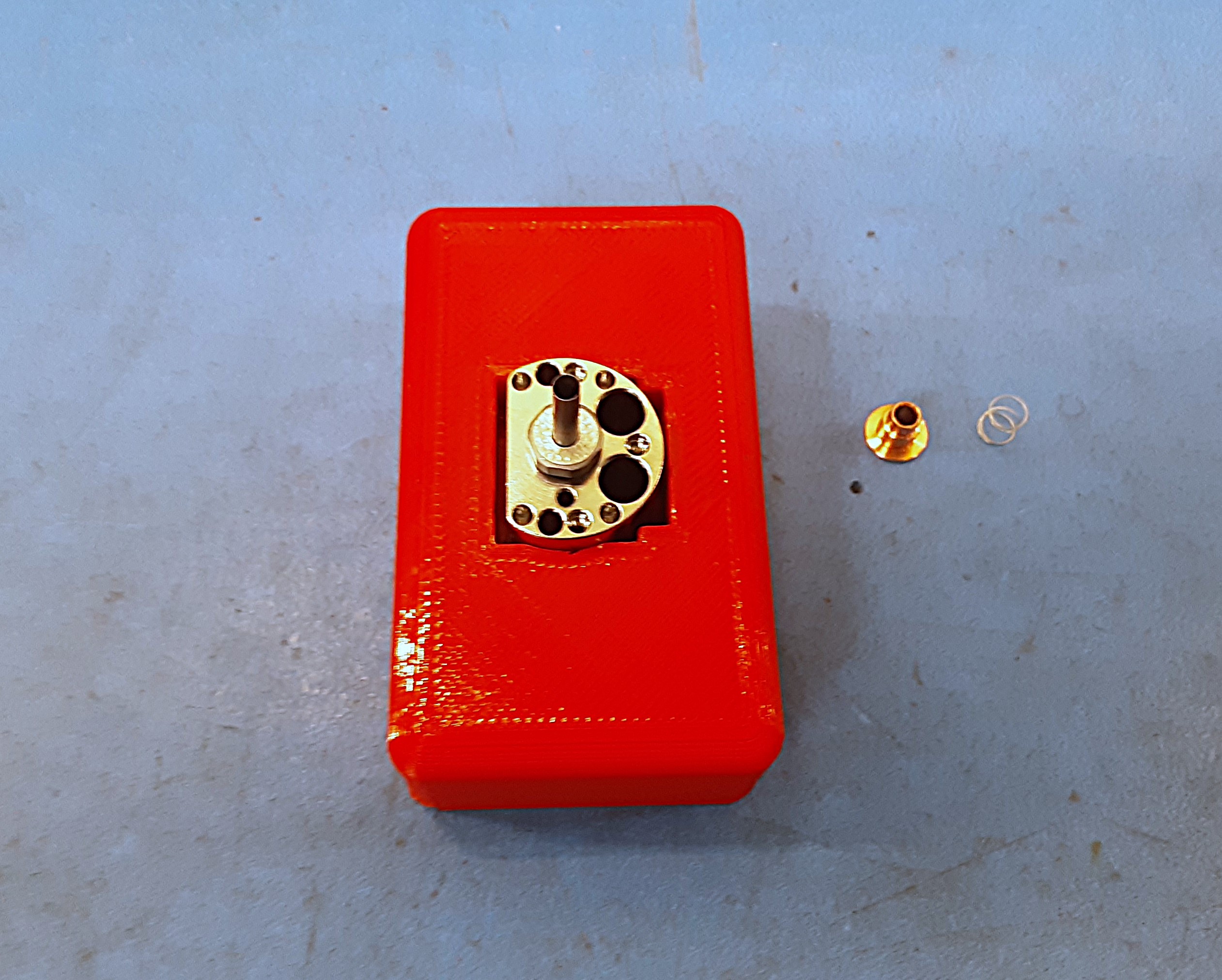
2A) Remove the copper part and spring from PP-MP0340 and screw into PP-MP0351 then place in the red jig block.
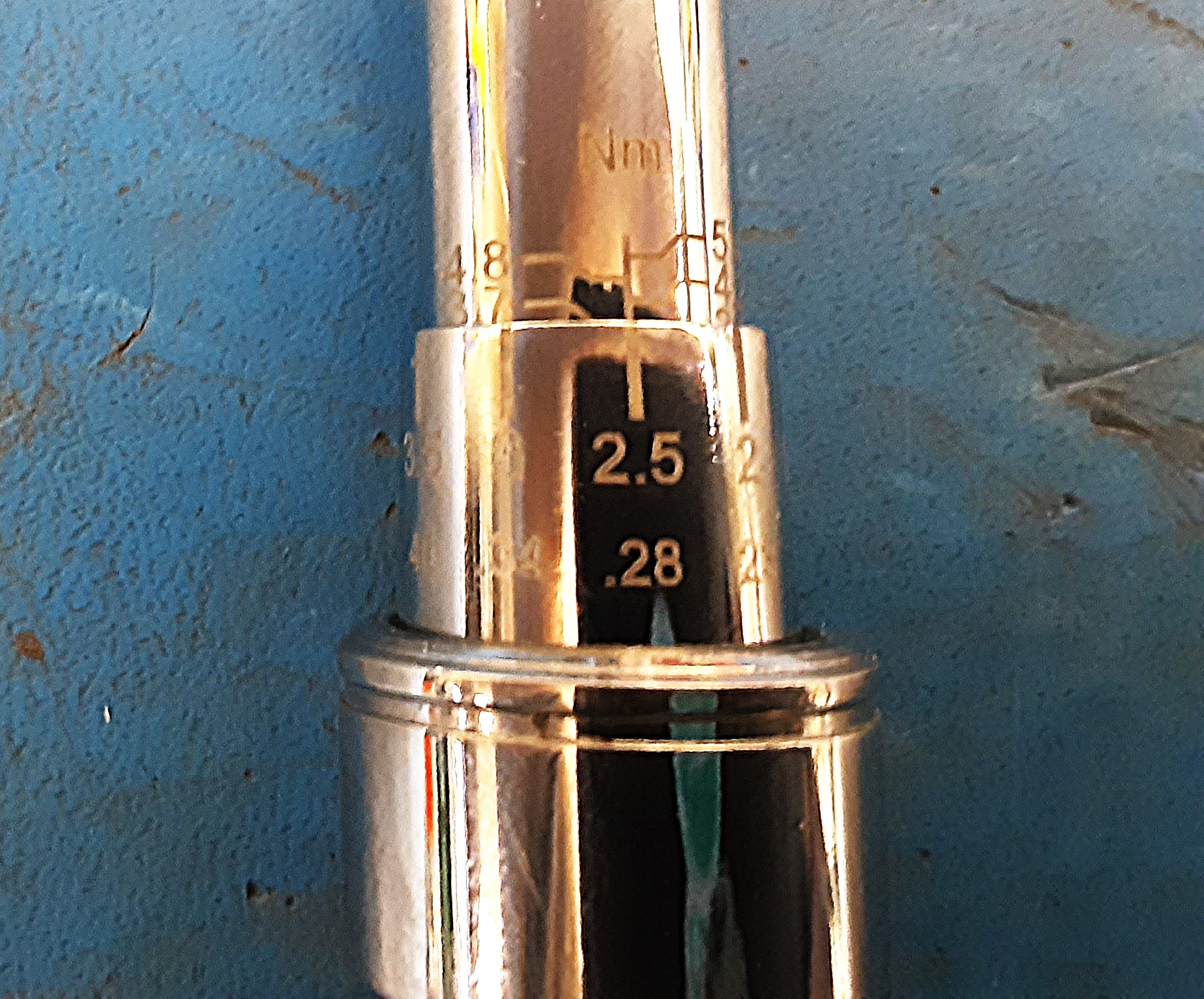
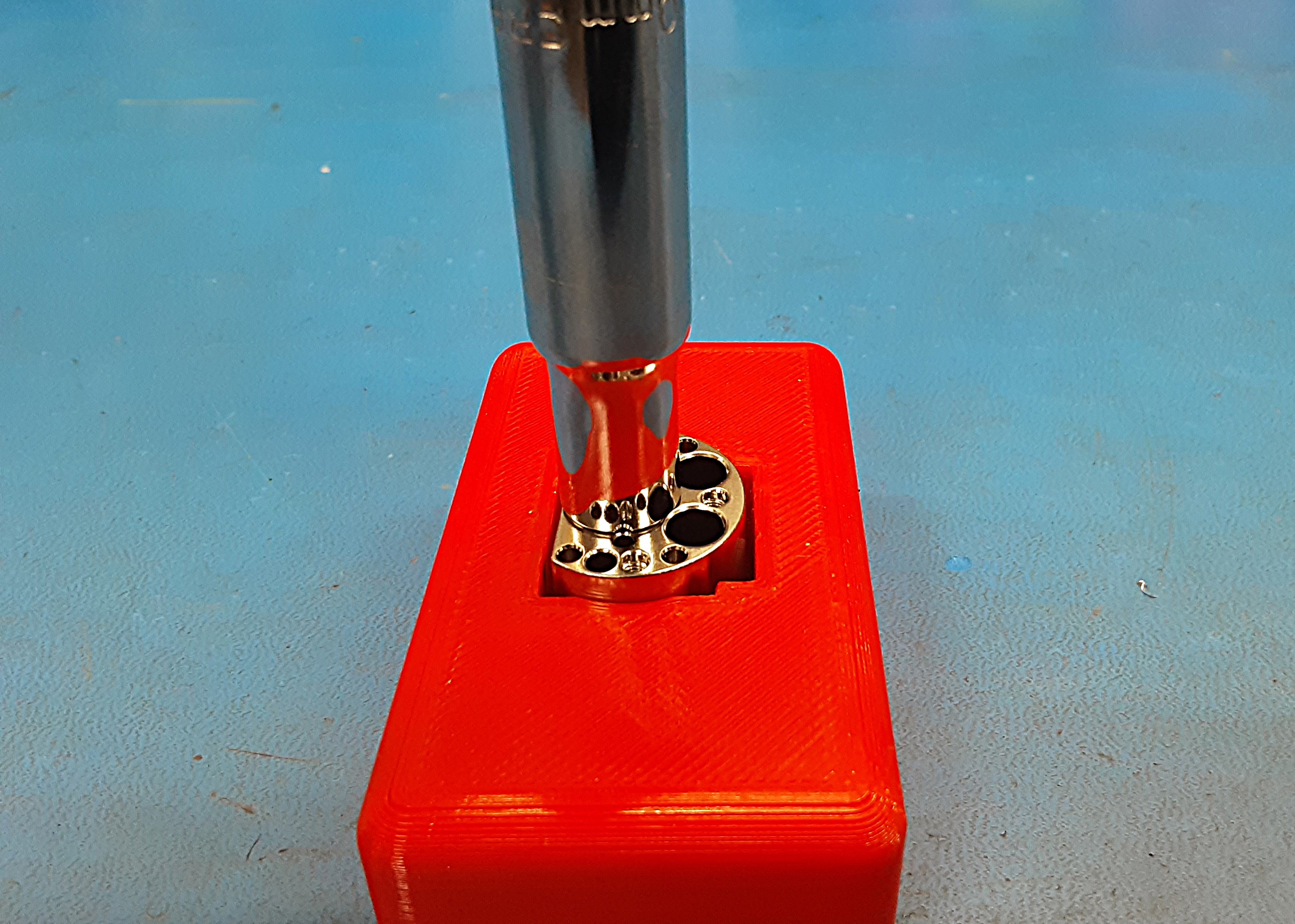
2B) Grab the torque wrench with a 9mm socket on the end. Double check that it is set at 3.98 NM.
2C) Torque the heat break into the hot block. Be sure to have the socket all the way down on the hot block when torqueing.
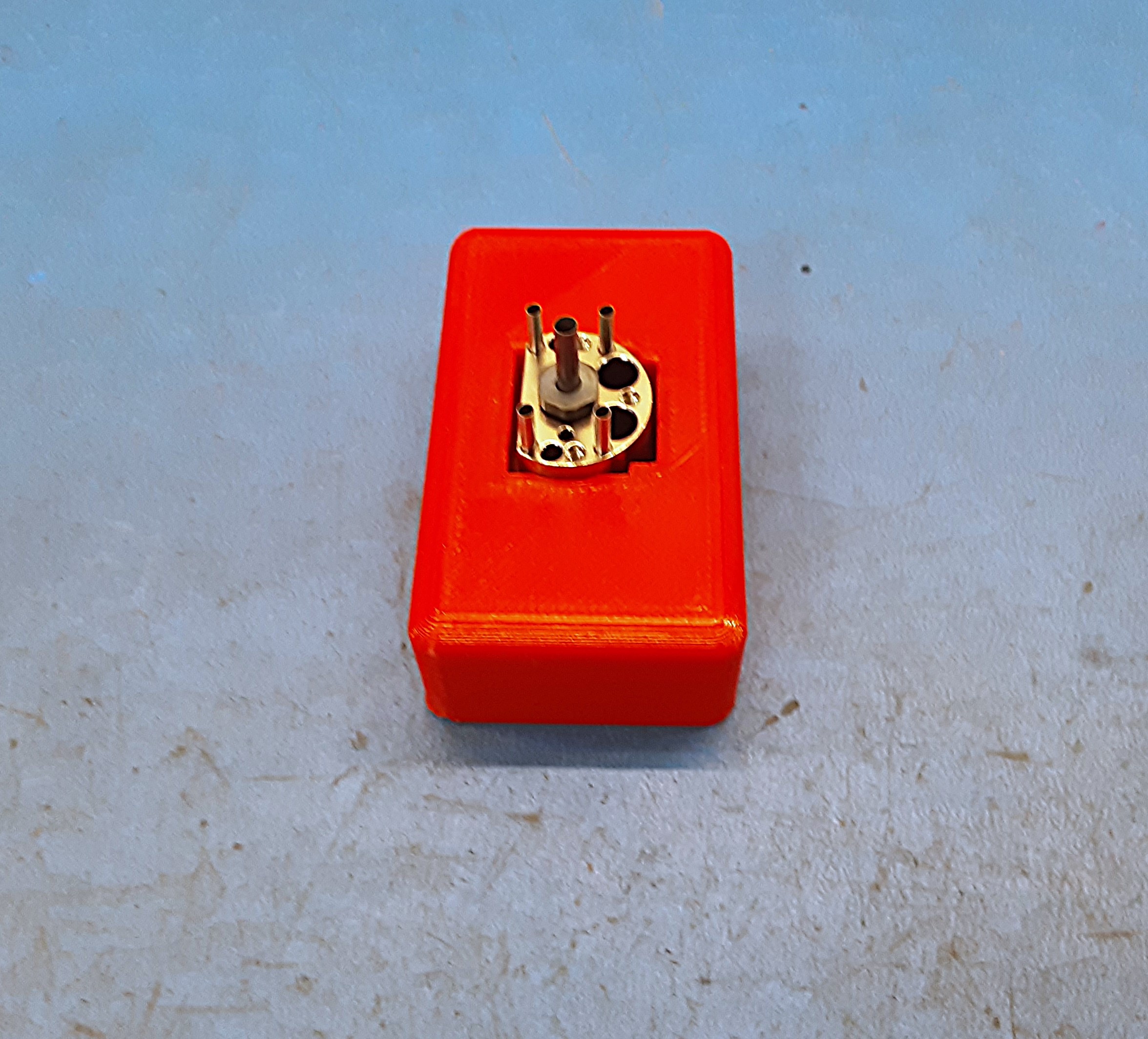
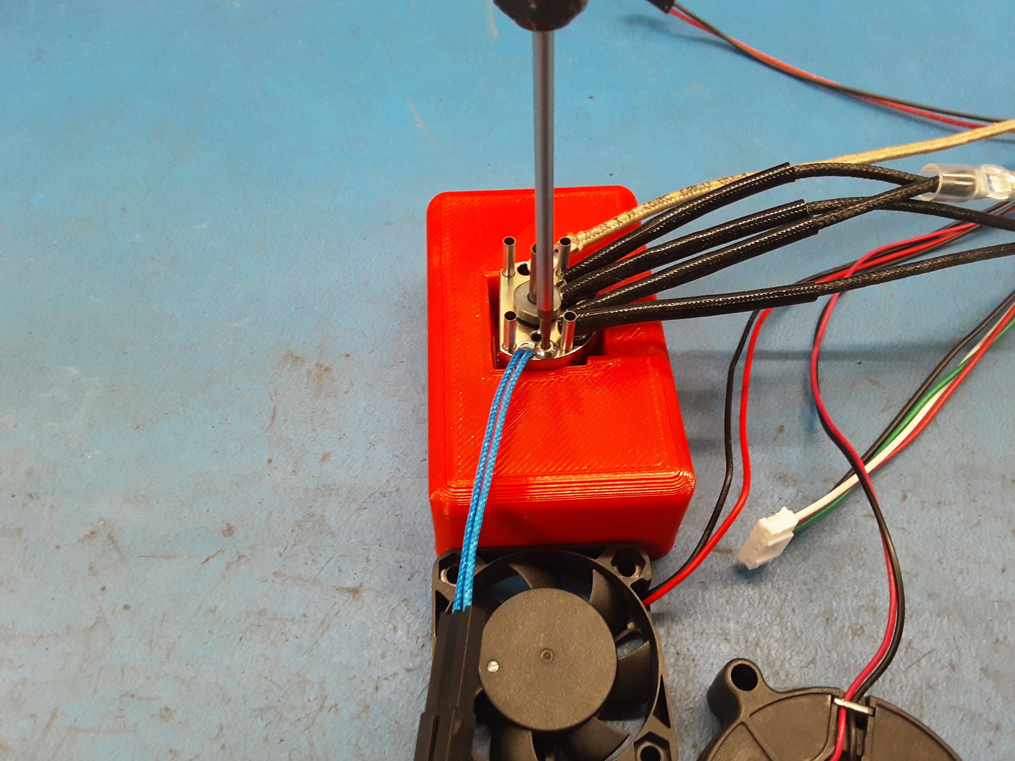
2D) Grab 4 posts from HD-MS0601 and insert them into the hot block.
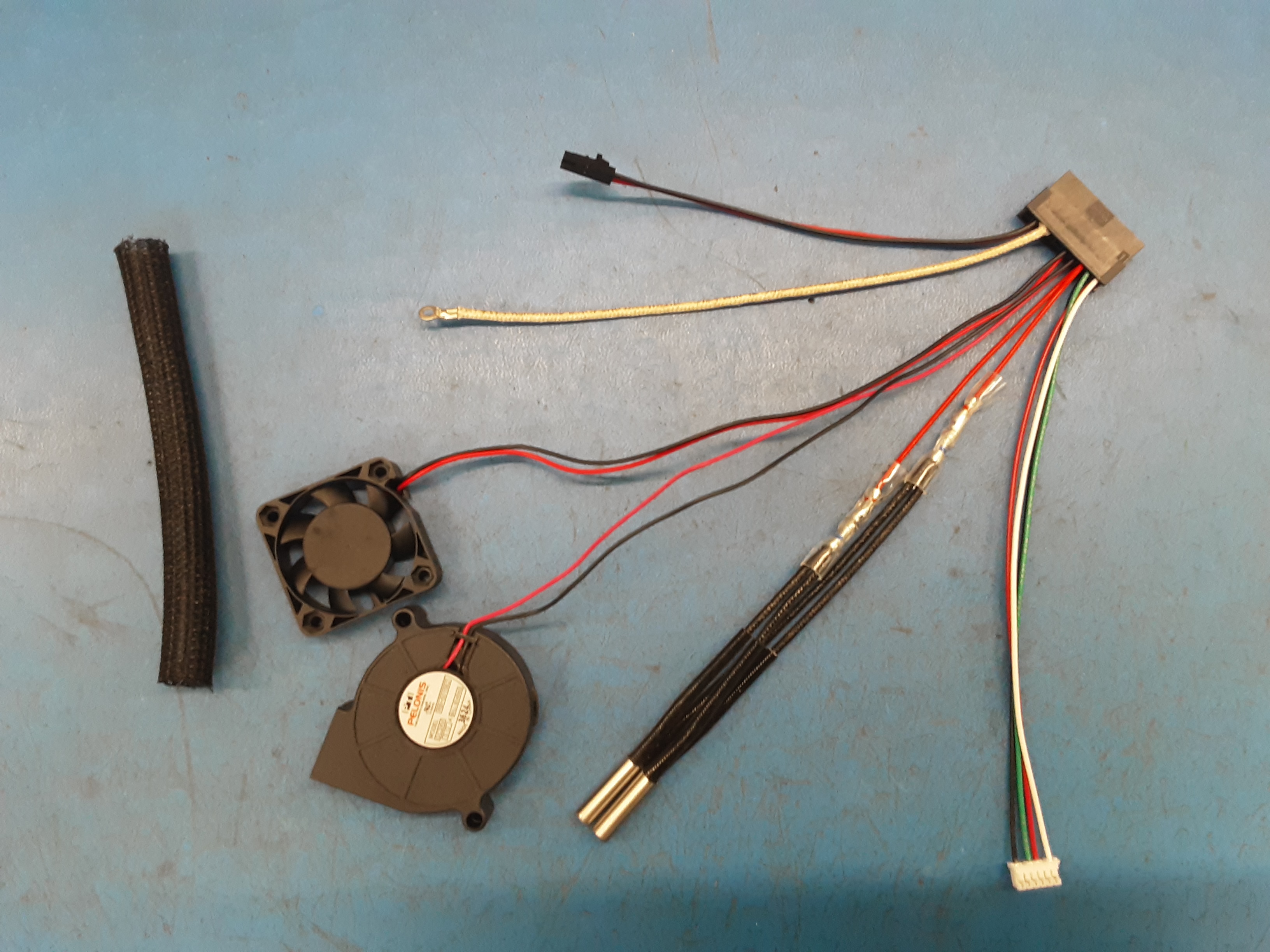
2E) Grab AS-CB0208 and remove the braiding from the wires. Make sure that none of the wires are twisted up.
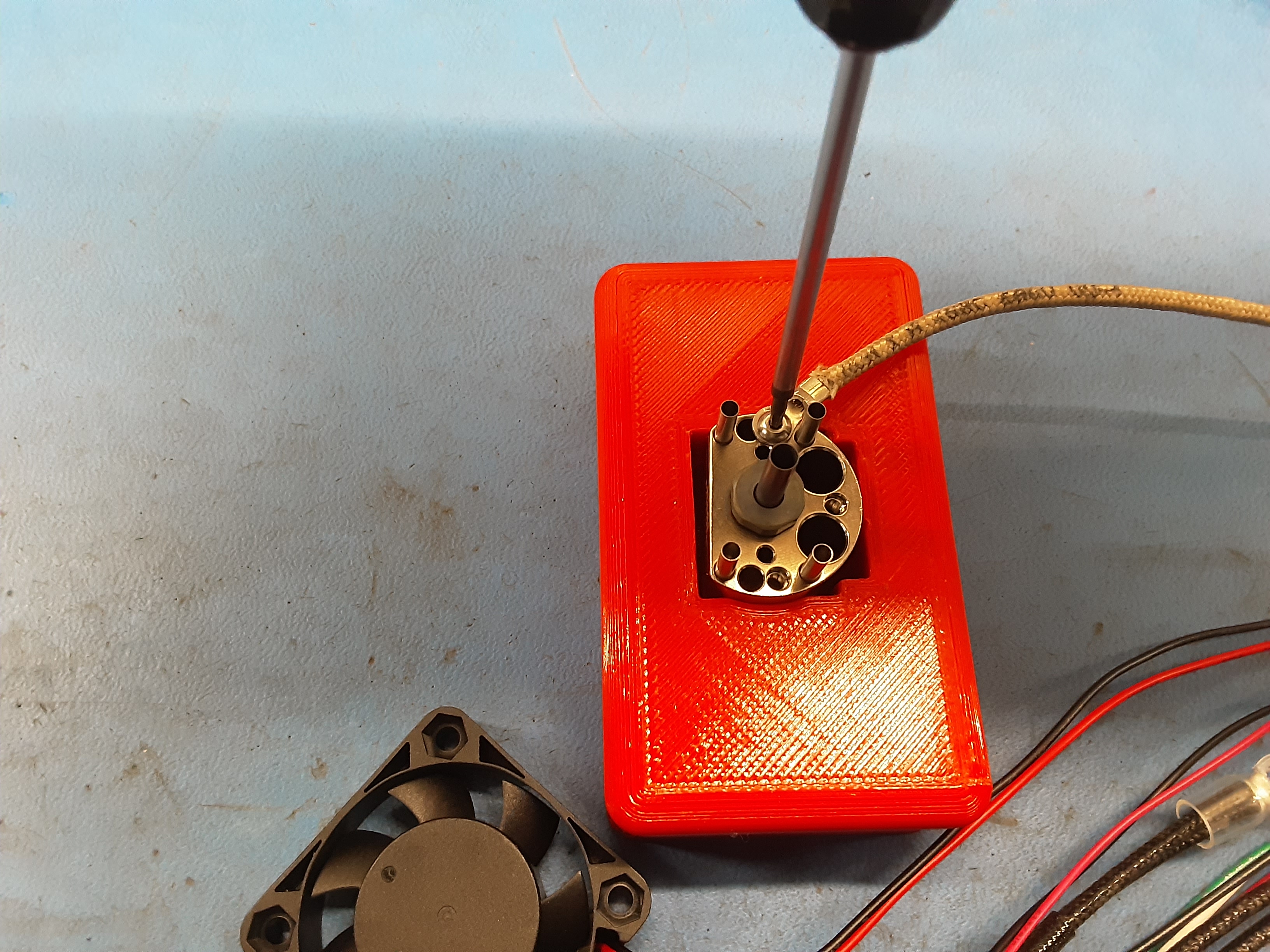
2F) Grab a #1 screw from HD-MS0601 and secure the ground wire in the spot shown. Be careful when tightening the screw. The wire should be close to the post but not against it and the hole close to the heat break needs to remain clear.
2G) Insert the heater cartridges into the spots shown and secure using #1 screw from HD-MS0601. Check to make sure the protective casing on the wires did not get pinched under the screw.
2H) Grab 1x EL-TH0012 and insert it where shown and secure using #1 screw from HD-MS0601.
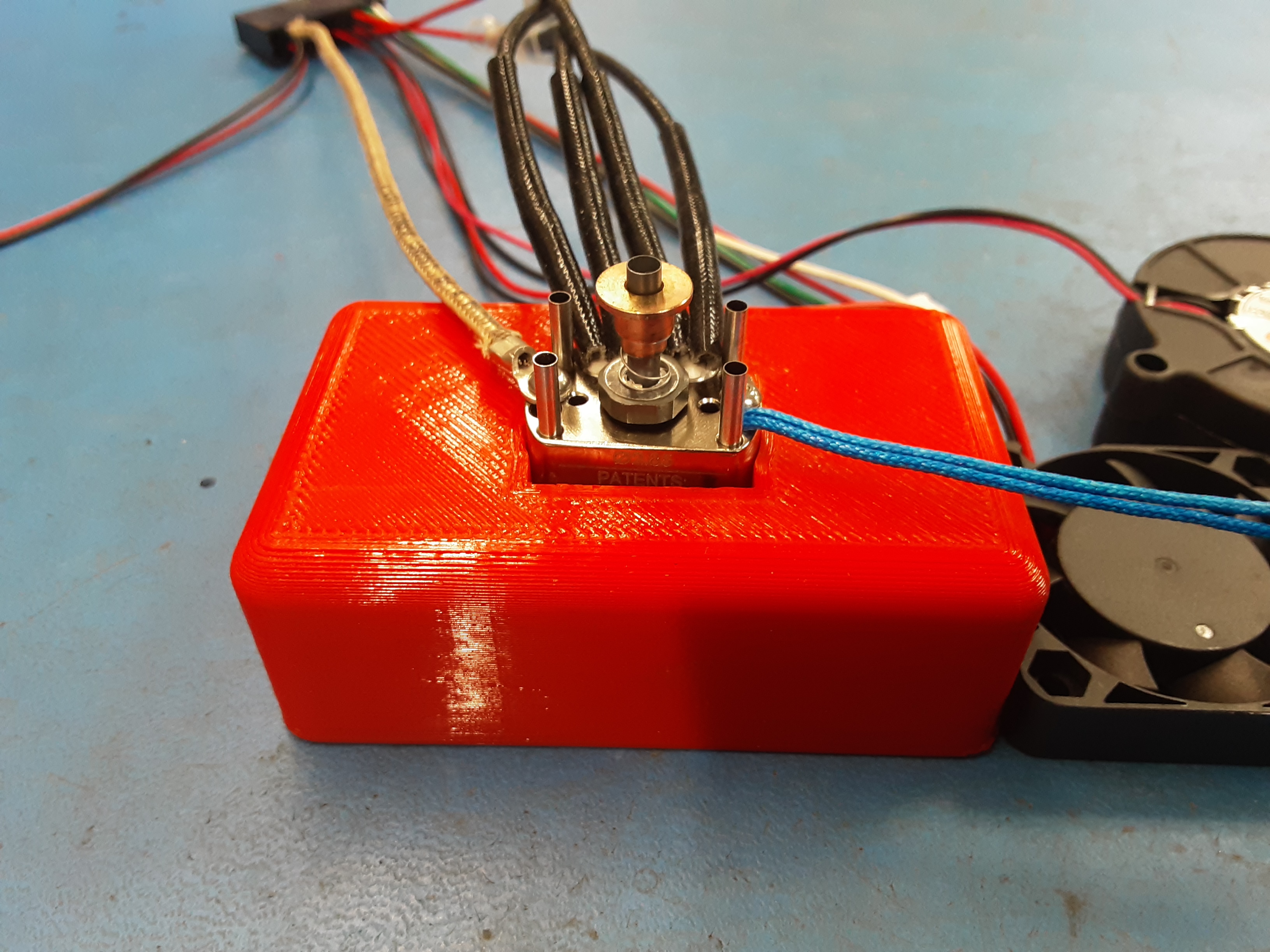
2I) Can put the previously removed spring and copper part back onto the heat break now.
2J) Grab two #2 screws and two washers from HD-MS0601. The washers go on the screw with the convex side towards the screw head. Screw with Washer |--(----
2K) Grab 1x PP-MP0350 and line it up with the four posts and heat break and push them together. Take the two #2 screws and washer and insert them into the shown holes.
2L) Secure the hot block to the heat sink by torquing the #2 screws. Double check to make sure the screws were tightened all the way.
2M) Install one #1 screw from HD-MS0601 on the thermistor side of the nozzle side of the hot block.
2N) Place 1x HD-MS0105 on the end of the heat break.


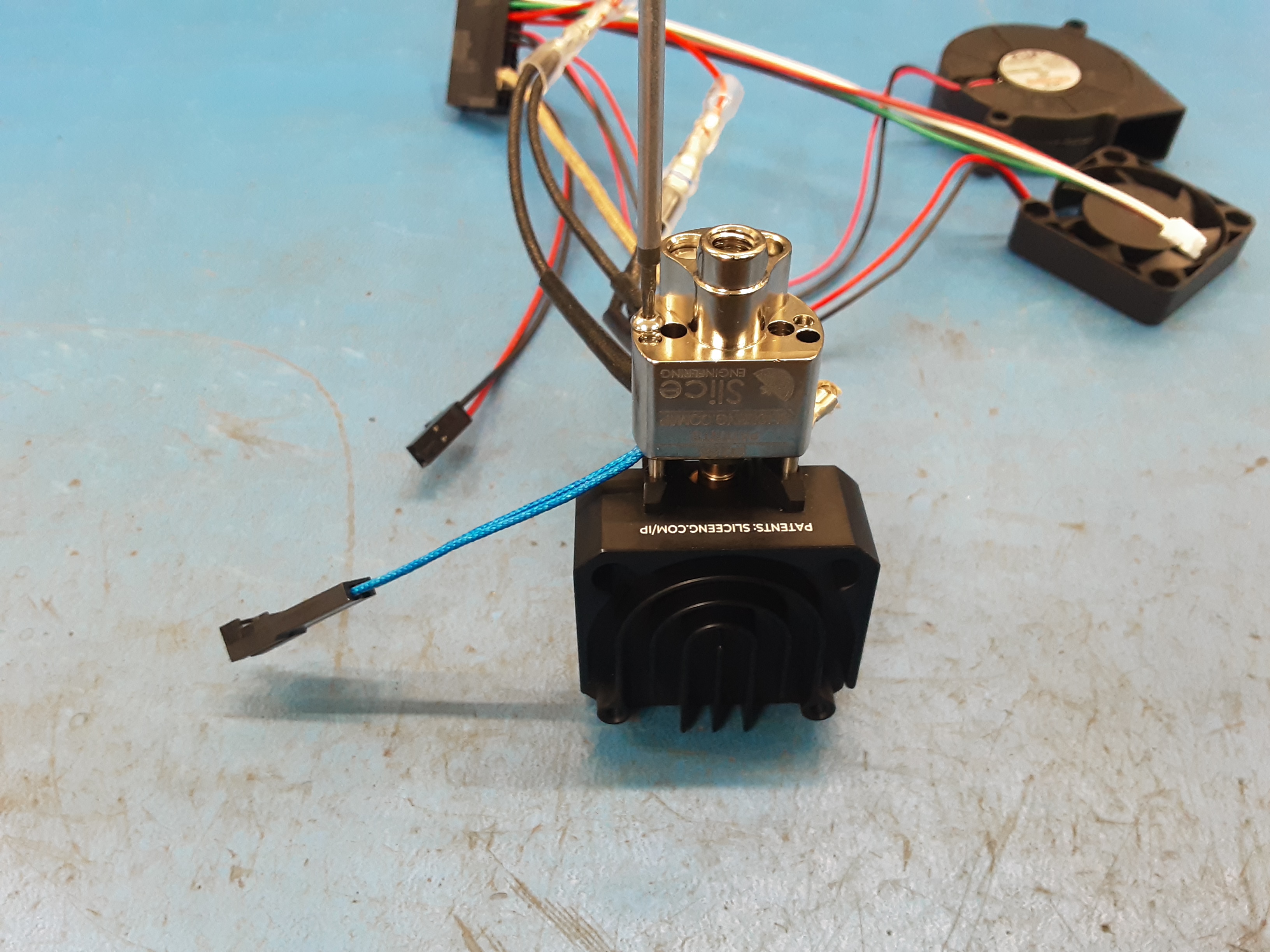

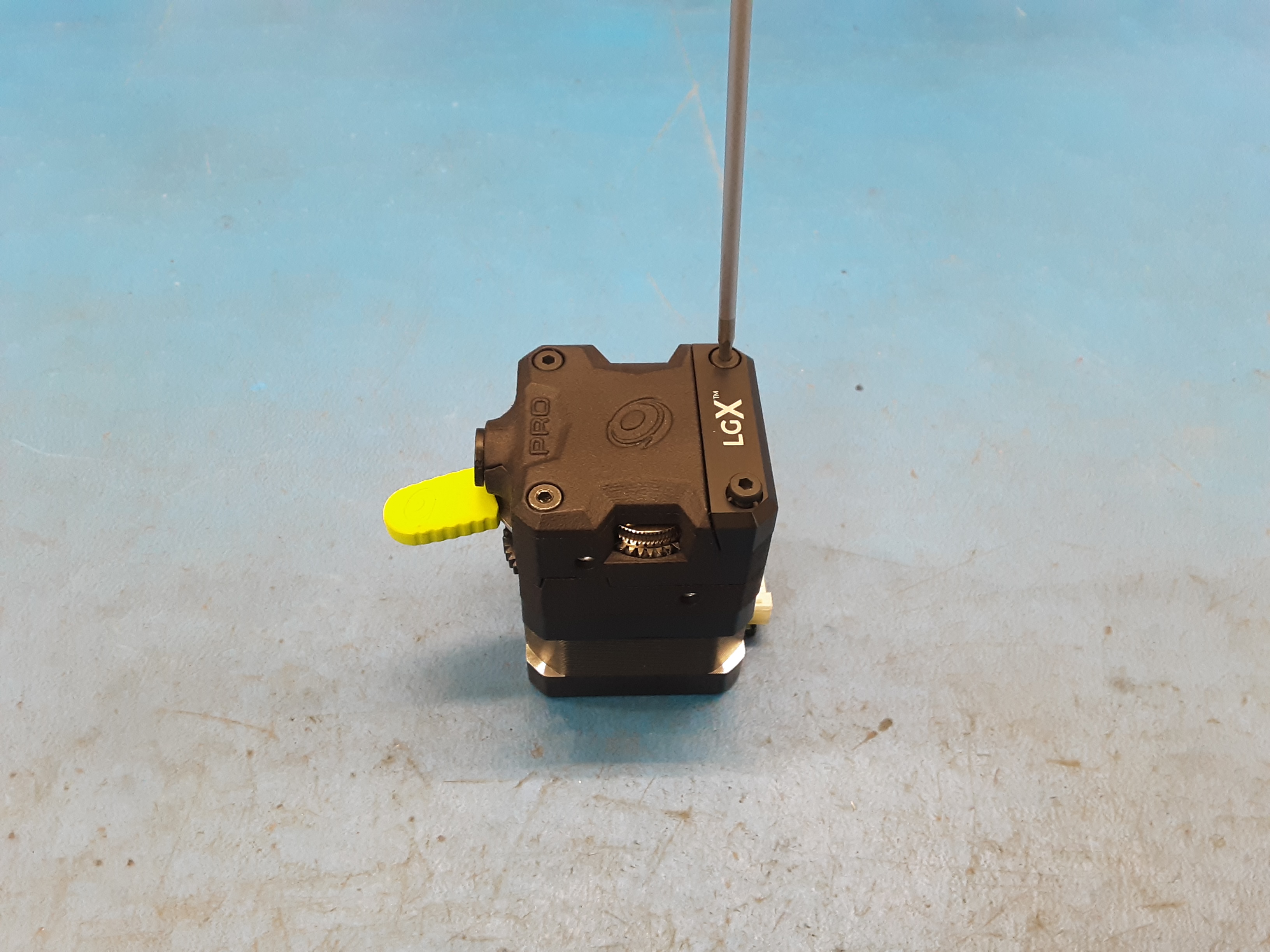
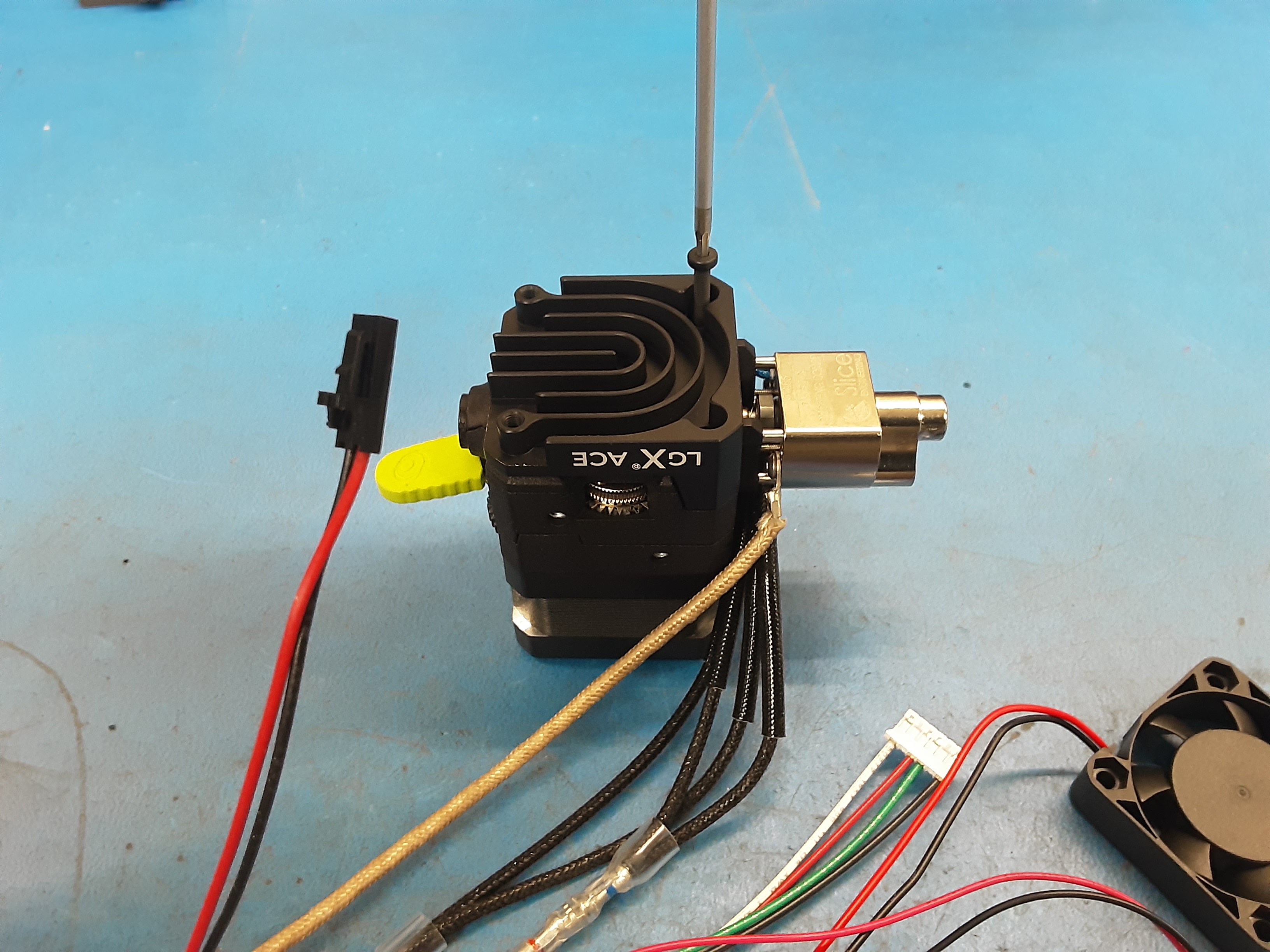
3A) Grab PP-MP0336 and remove the 2 screws from the LGX block and remove the LGX block. Save the screws but, the LGX block will not be used again.
3B) Using the 2 screws from the LGX block install the Hot Block Assembly onto PP-MP0336.
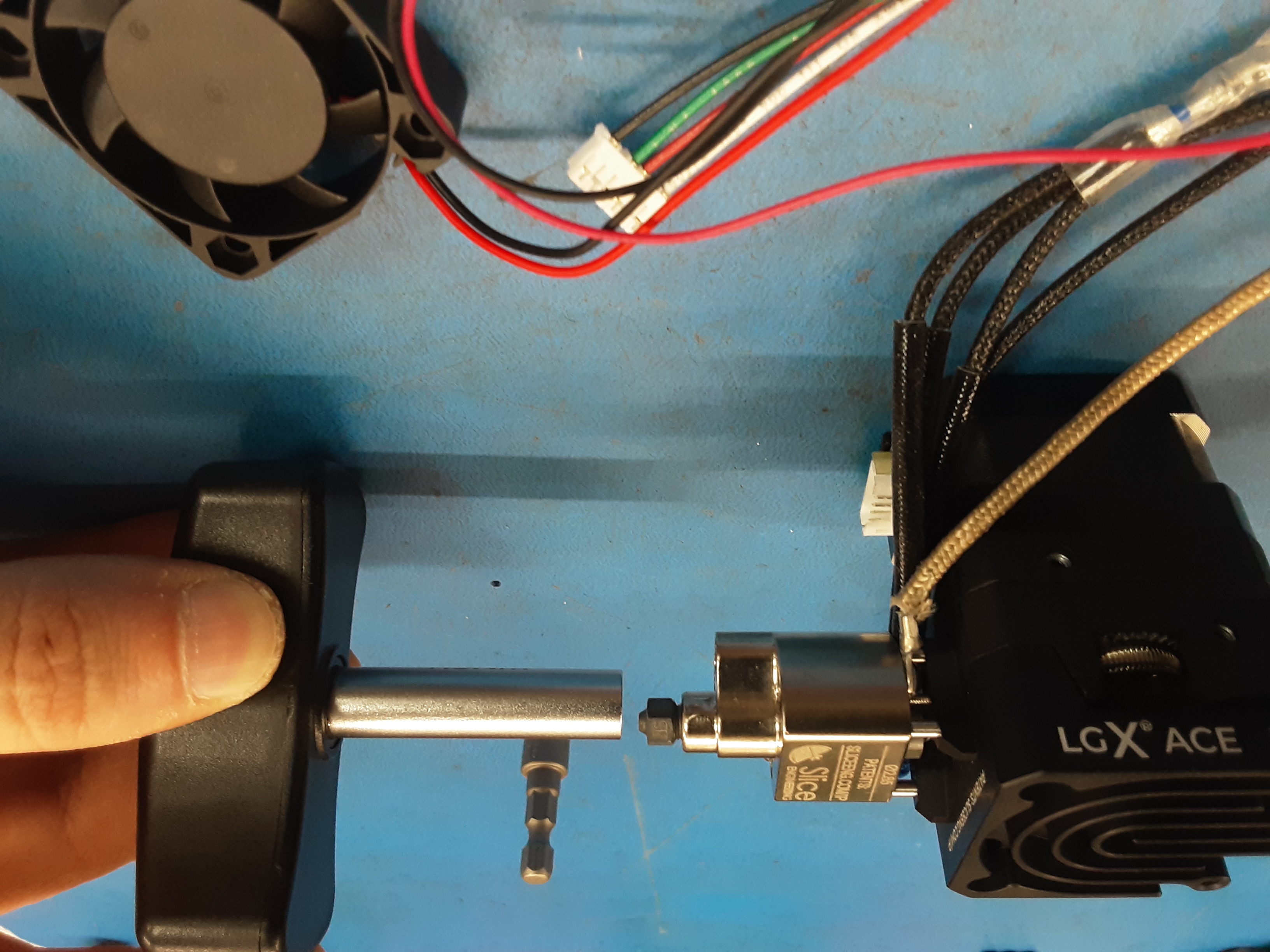
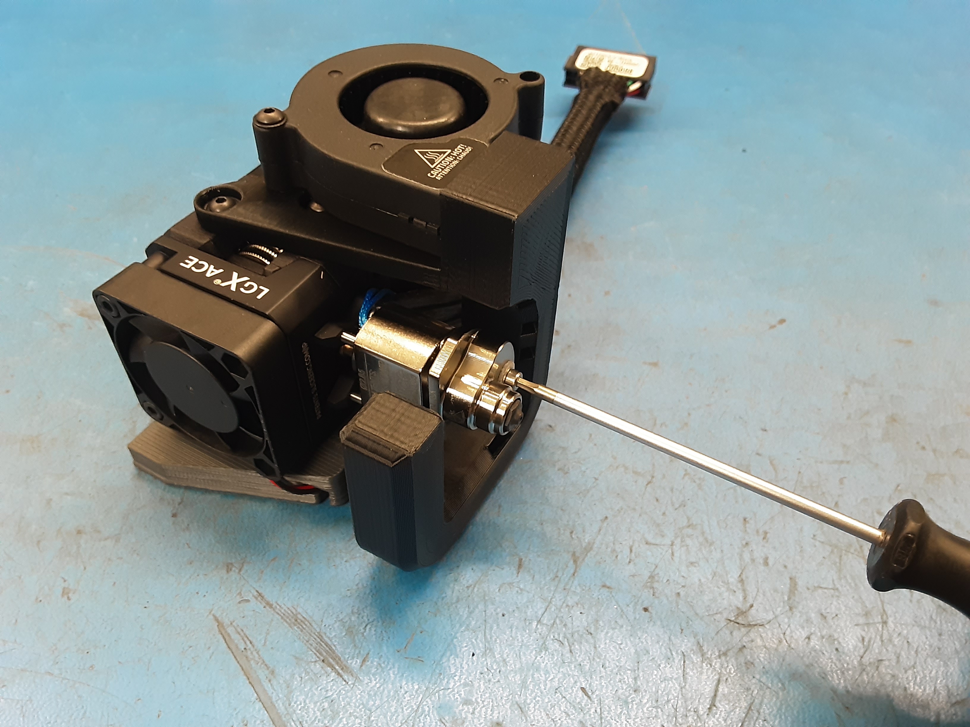
3C) Grab 1x PP-MP0501 and install it in PP-MP0351 using the nozzle torque tool.
3D) Grab 1x PP-GP0731, 2x HD-BT0039, and 2x HD-WA0038.
3E) Install PP-GP0731 on the shown side of PP-MP0336 using 2x HD-BT0039 and 2x HD-WA0038.
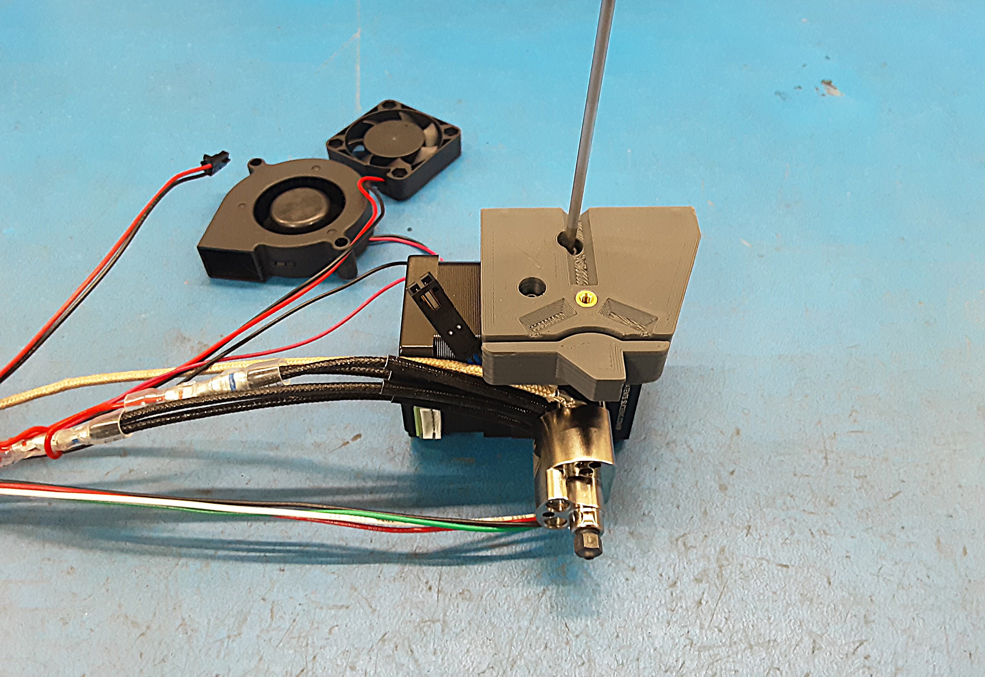
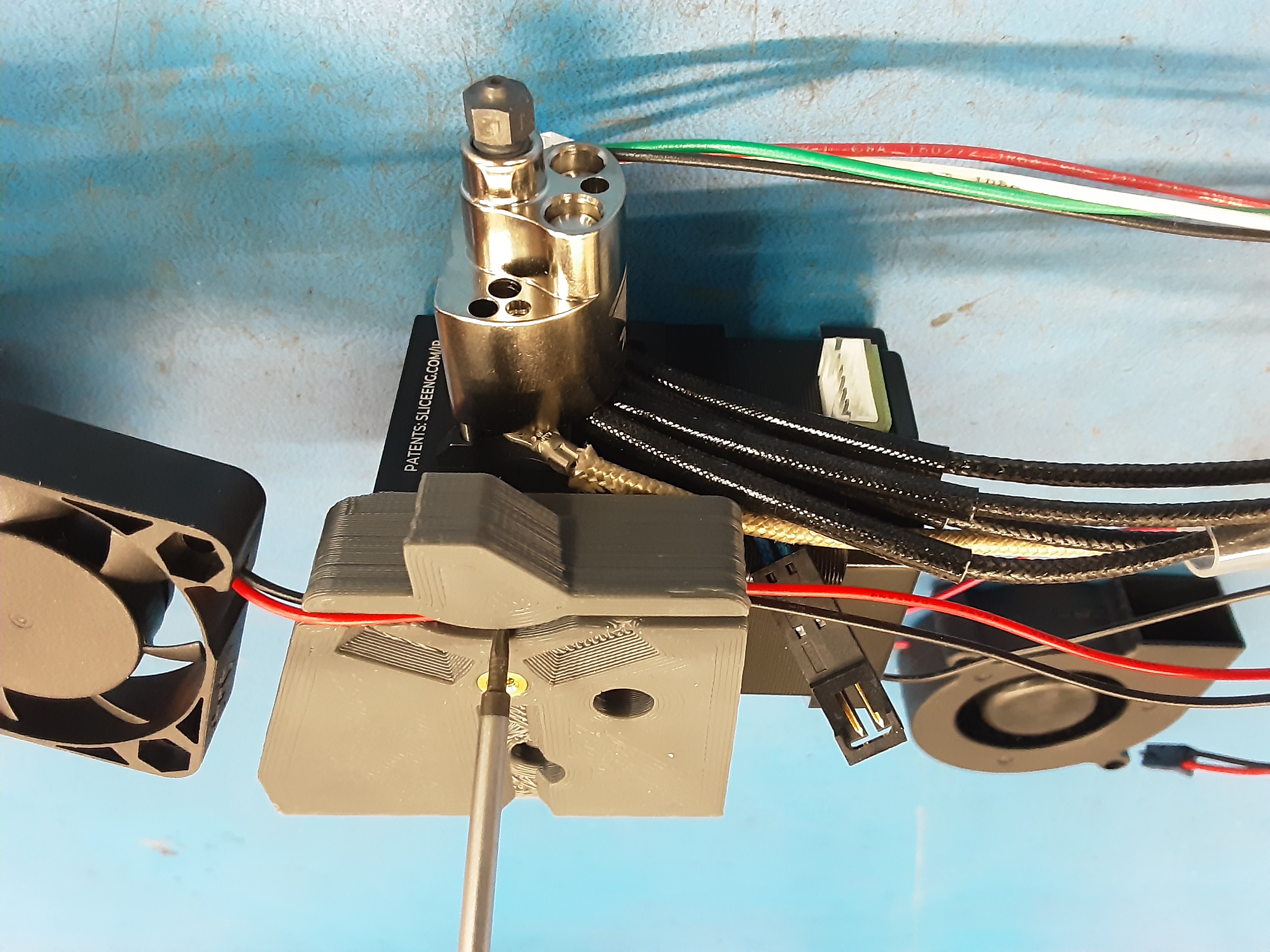
3F) Take the square fan from AS-CB0208 and run the wires through the channel in PP-GP0731. Make sure the wires get all the way into the channel.
3G) Install the square fan onto PP-MP0350 using 2x HD-BT0005.
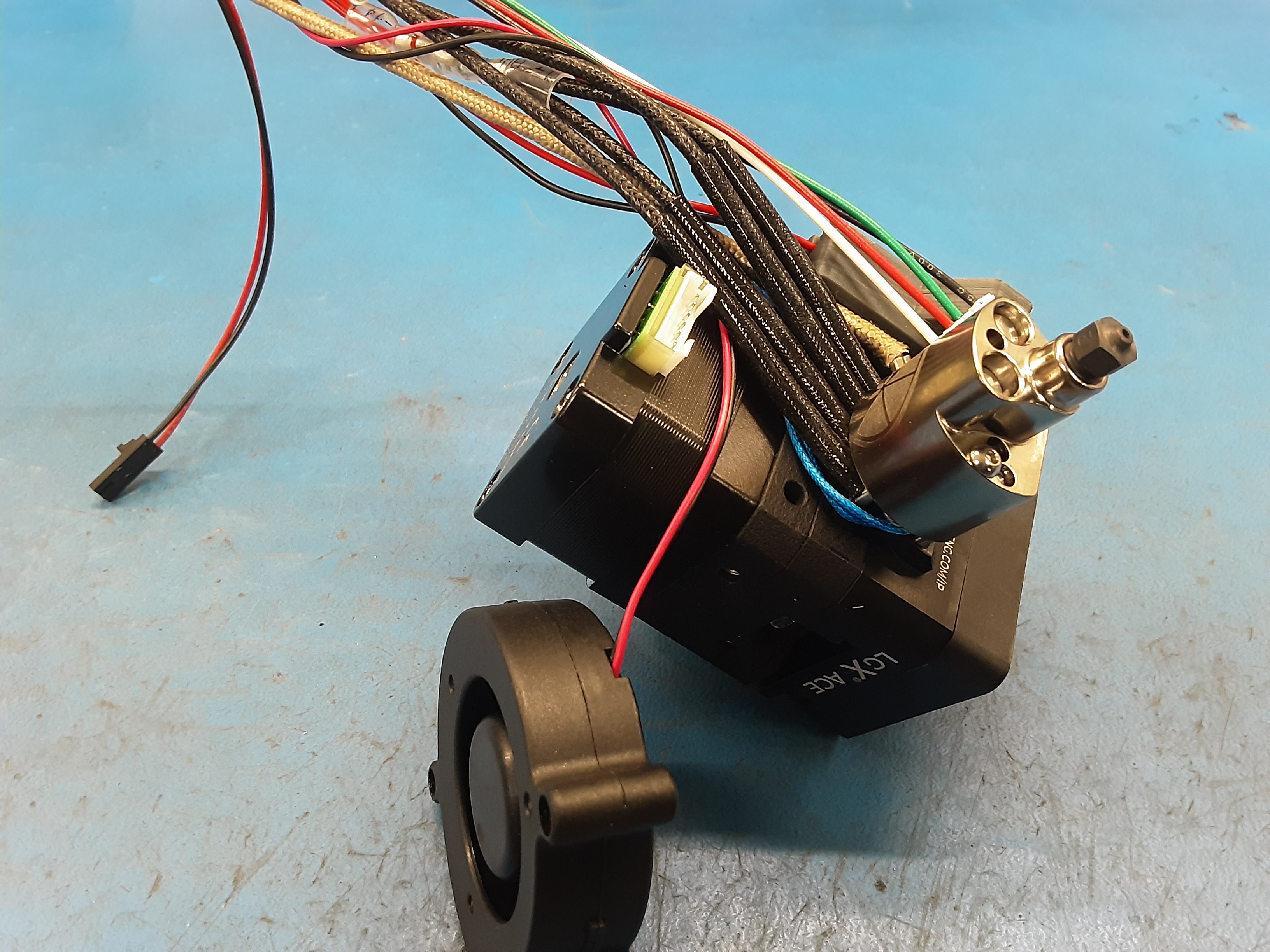
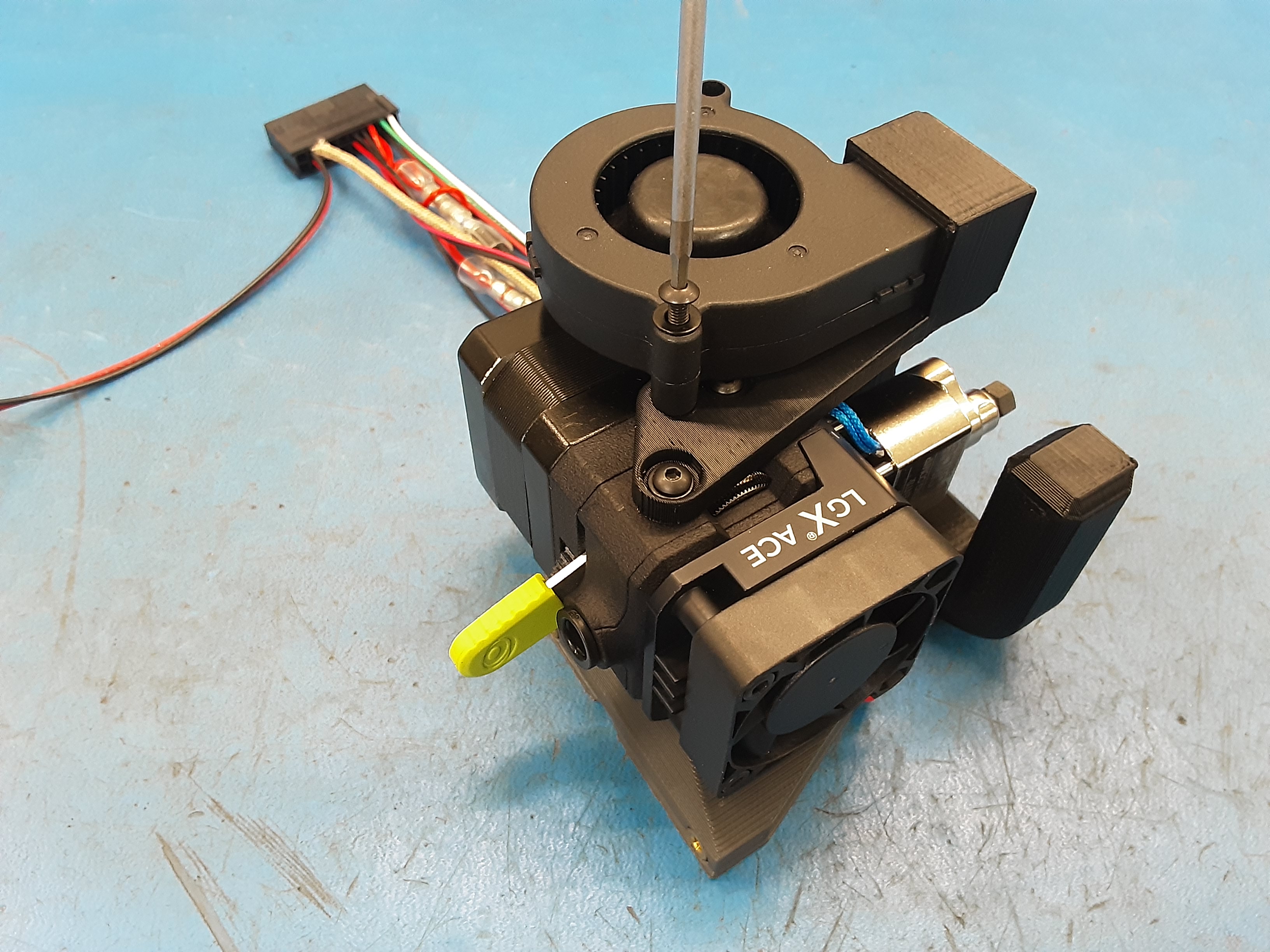
3H) Run the blower fan wire to be in between the motor and the rest of the wires.
3I) Plug the motor wires into the motor.
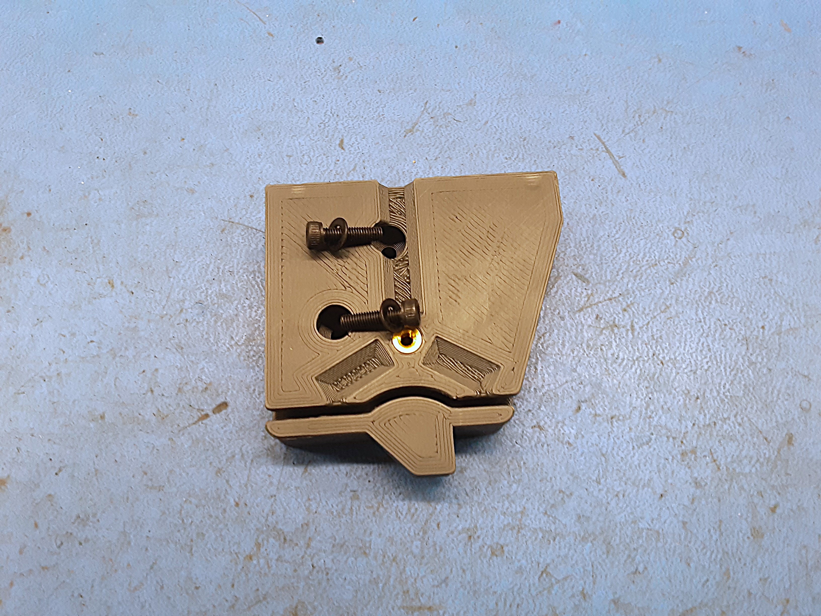
3J) Grab 1x PP-GP0732, 3x HD-BT0137, and 3x HD-WA0038.
3K) Attach PP-GP0732 to PP-GP0731 using 1x HD-BT0137 and 1x HD-WA0038.
3L) Finish attaching PP-GP0732 using 2x HD-BT0137 and 2x HD-WA0038 into PP-MP0336.
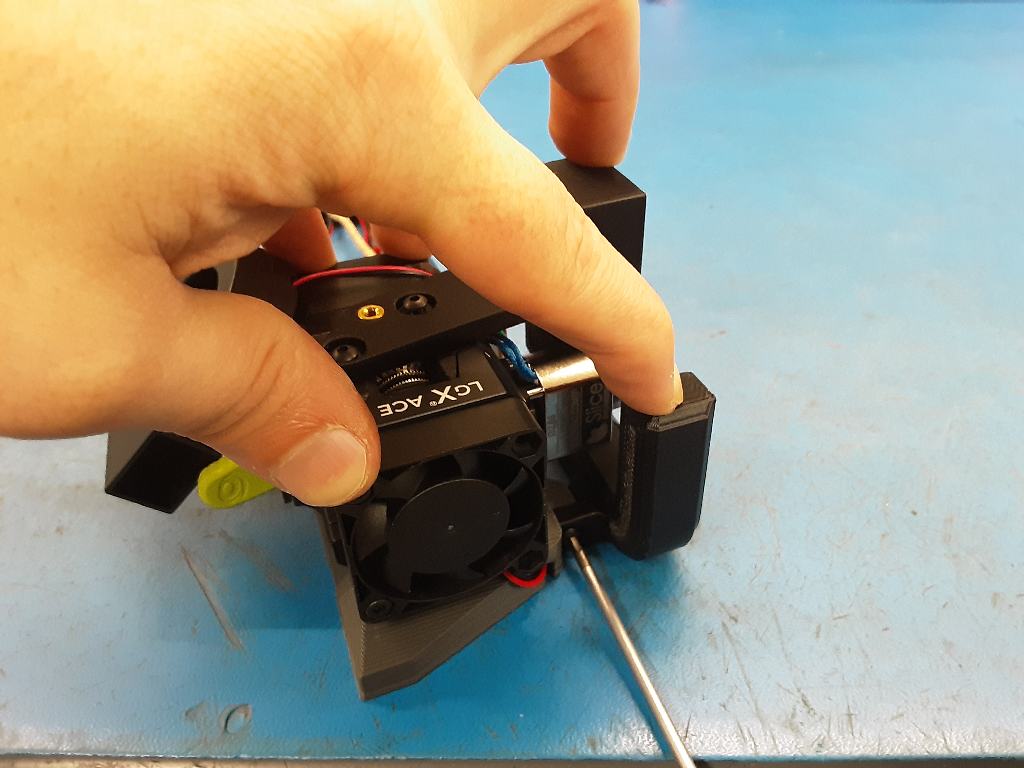
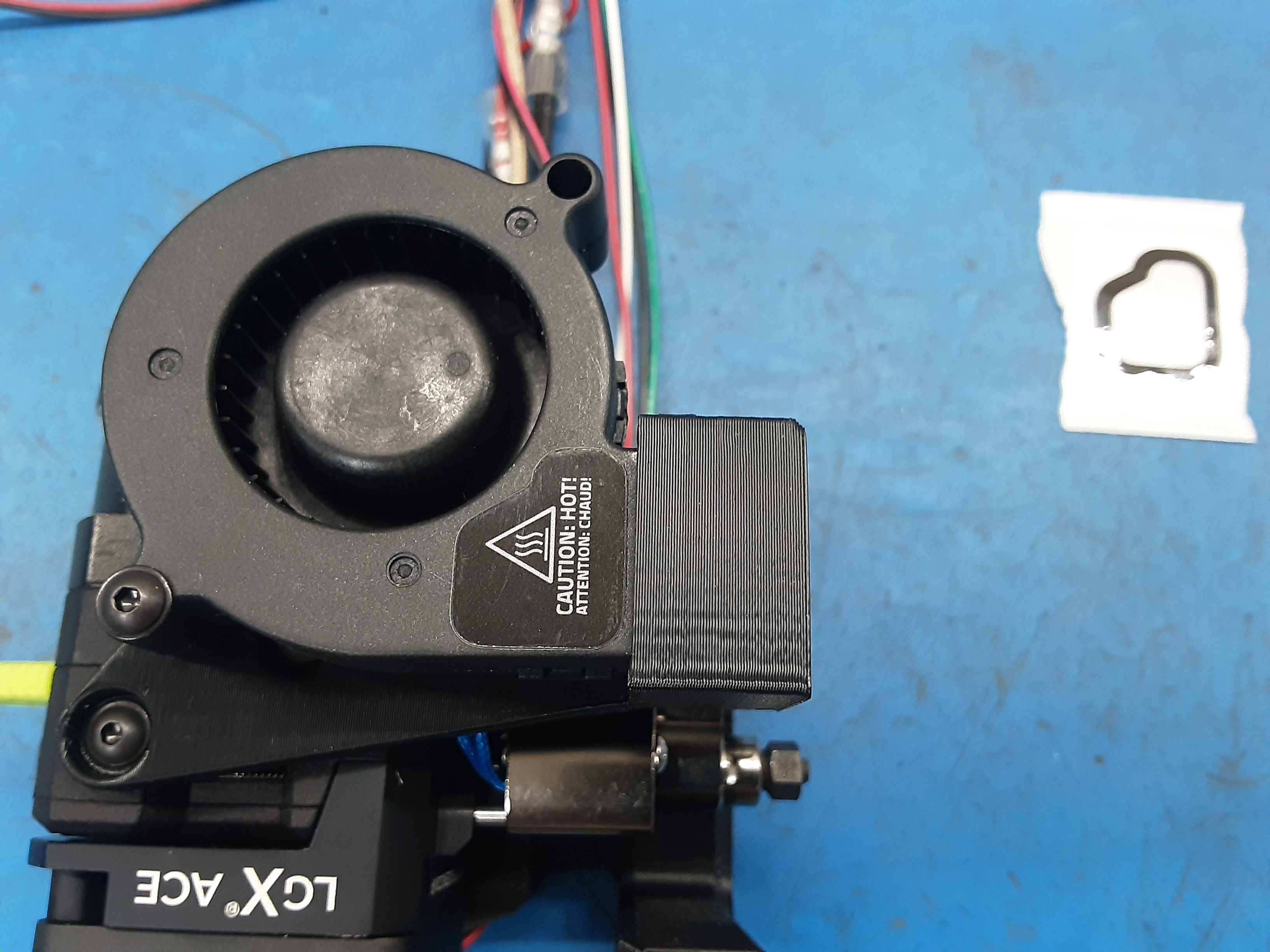
3M) Insert the blower fan into PP-GP0732 and attach using 1x HD-BT0171 and 1x HD-WA0038.


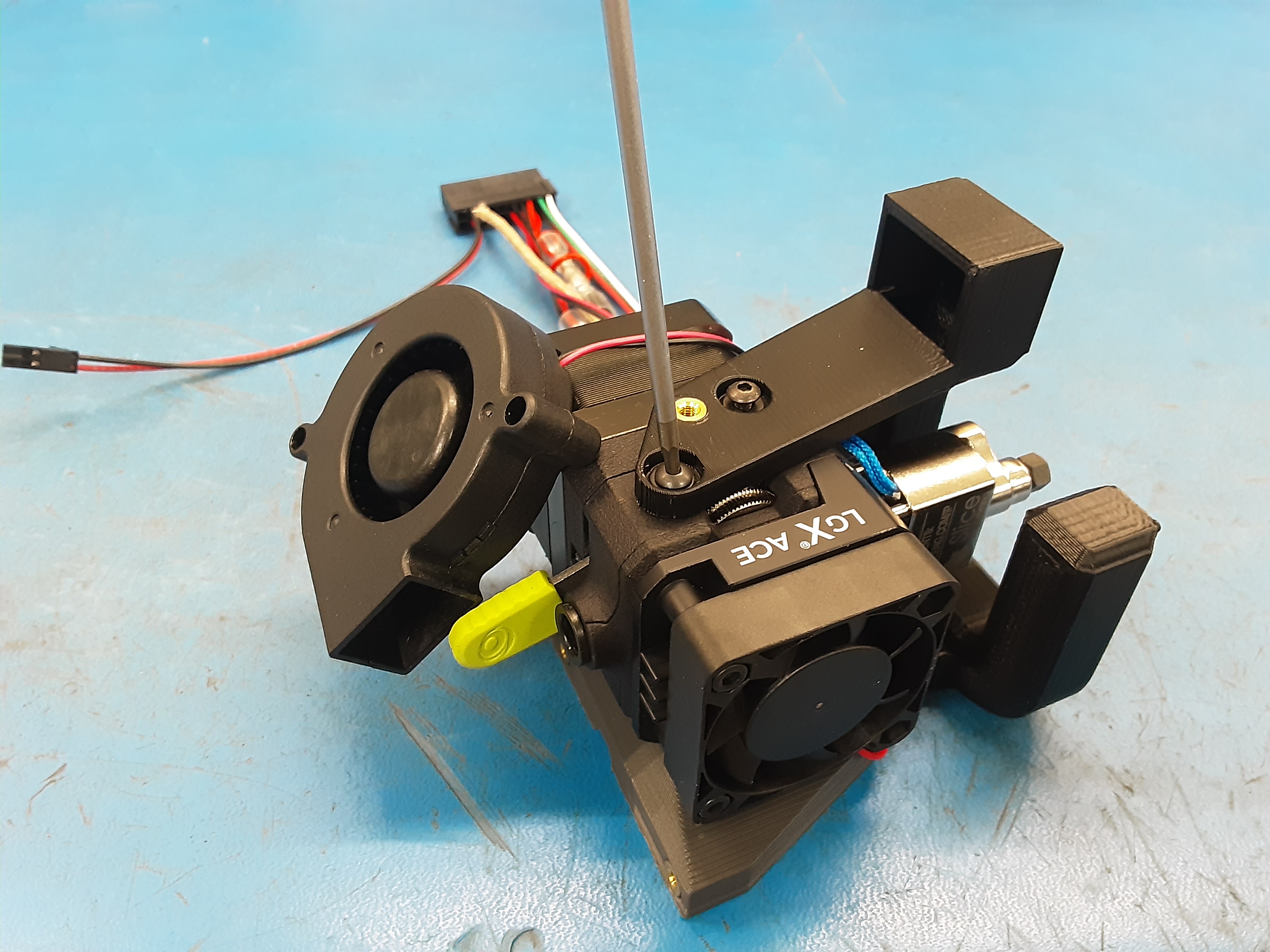
4A) Stick 1x DC-LB0154 sticker onto the blower fan where shown.
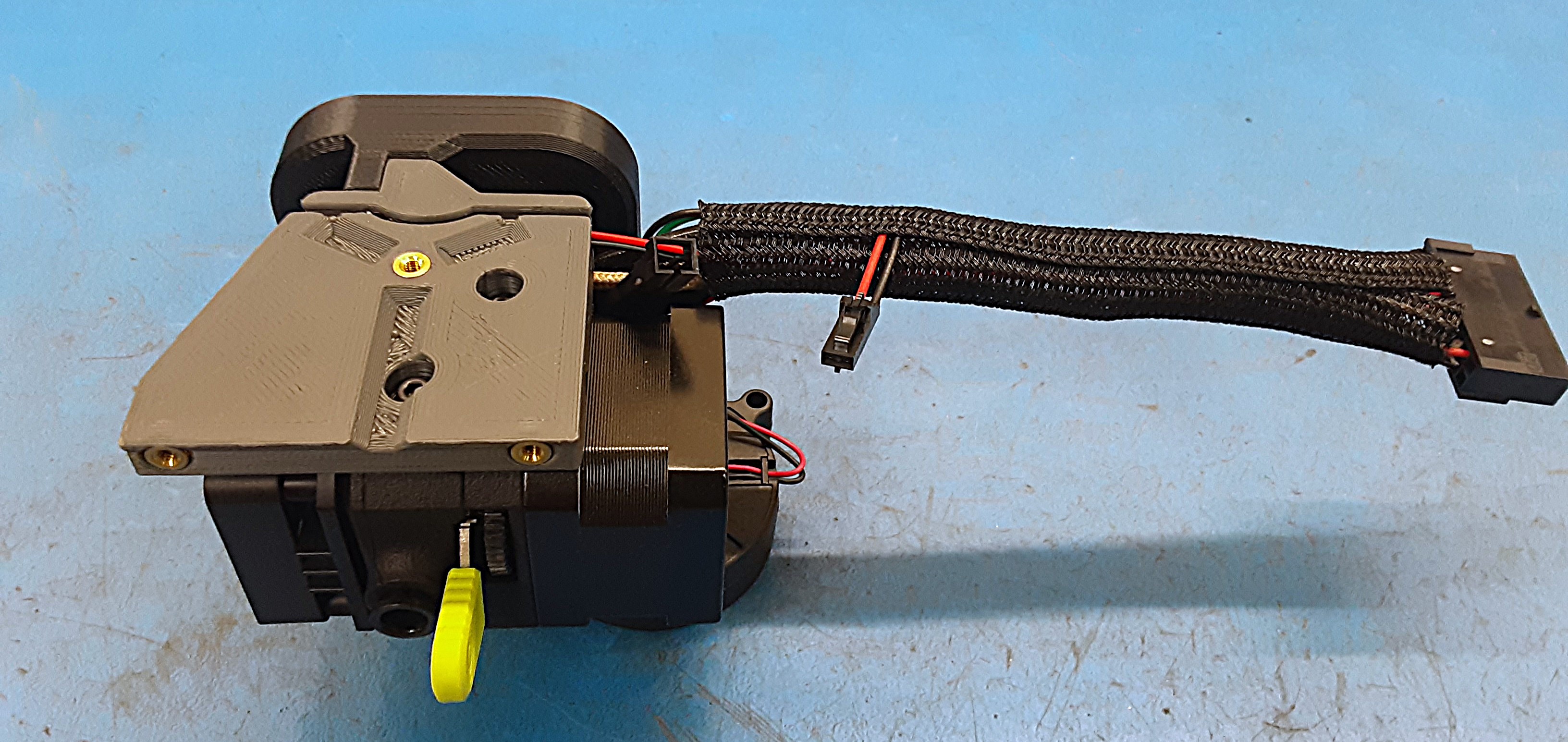
4B) Reattach the braiding onto the wires having the thermistor wires sticking out the side.
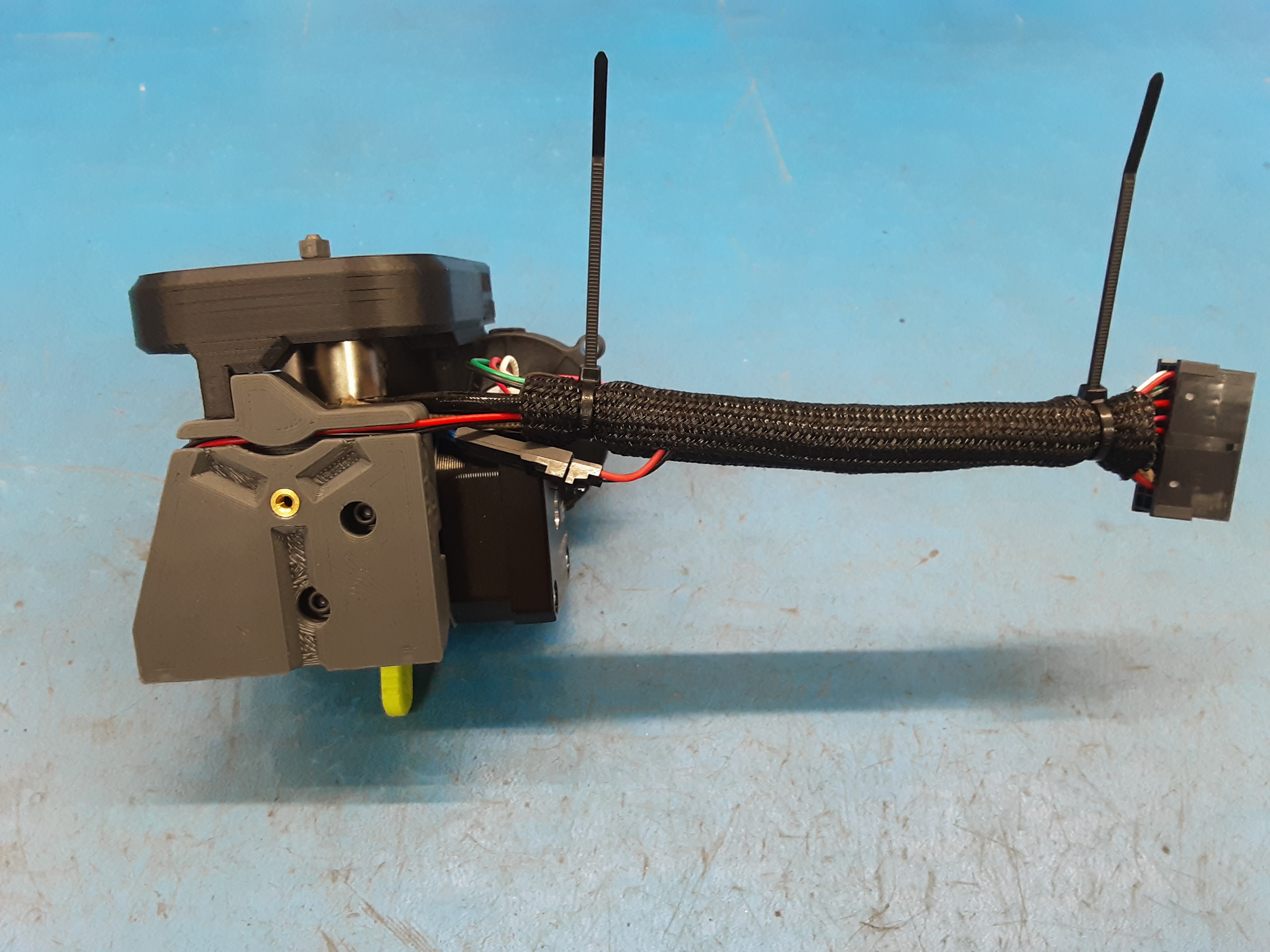
4C) Use 2x HD-MS0588 to secure the braiding on the wires. Be sure to have the thermistor wire sticking out in between the two zip ties. Plug the thermistor into the wires.
4D) Stick 1x DC-LB0160 onto the connector of AS-CB0208 and 1x DC-LB0160 onto PP-MP0336 where shown.
4E) Install PP-MP0353 onto PP-MP0351.


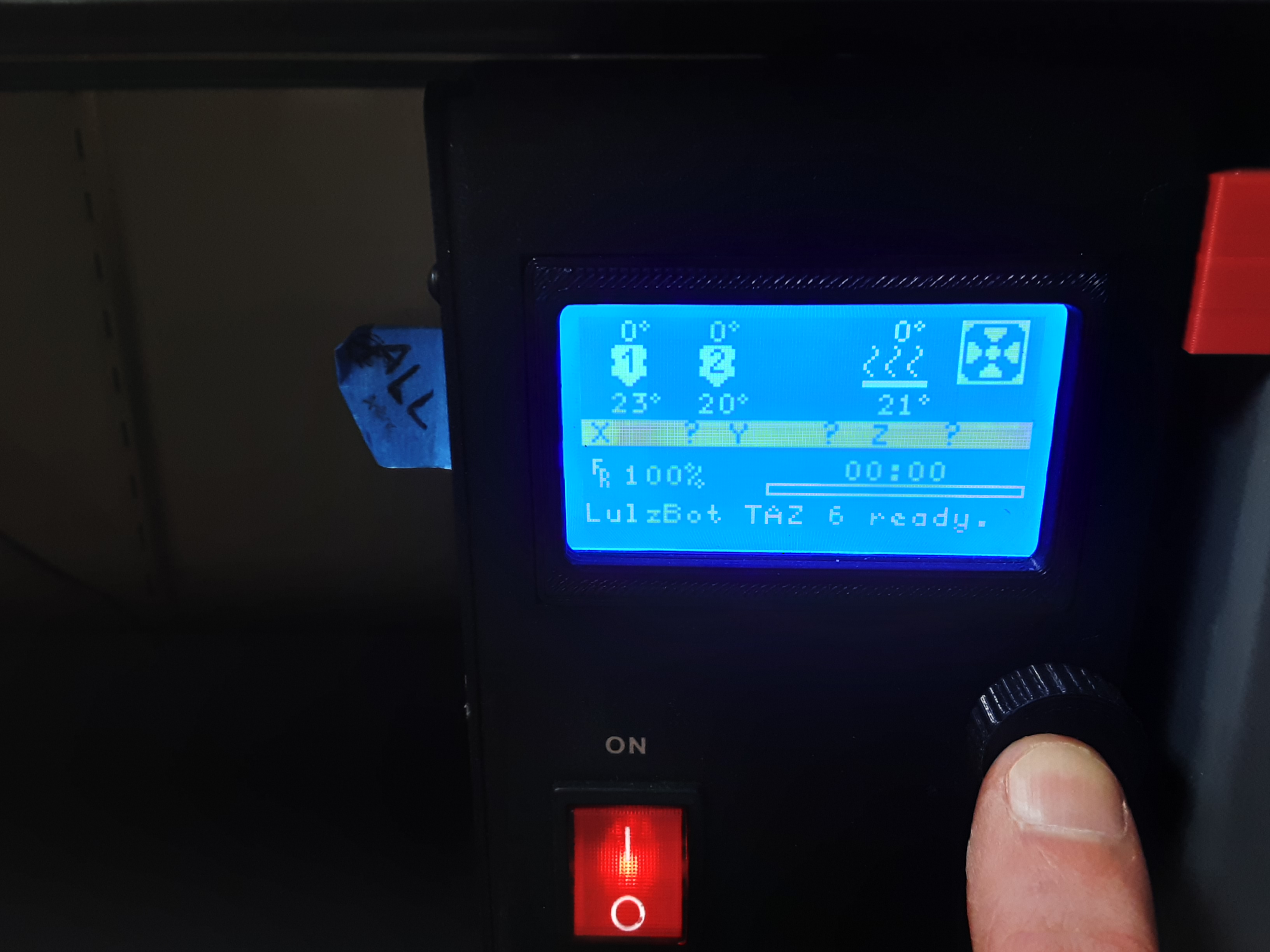
5A) Plug the tool head into the #1 test plug and the thermistor jumper into the #2 test plug.
5B) Turn on the test printer and push the knob in.
5C) Scroll down and select “Print From SD”
5D) Select “Aero-Style-x1.gcode”
Note:
Only one Asteroid tool head can be tested at a time.
The square fan should always be on while the printer is on. After selecting a print the blower fan should kick in briefly and the tool head should start to heat up. Once the tool head heats up the motor will cycle. After that the blower fan will turn on to cool down the tool head. .