Open HardwareAssembly Instructions
Guides for installation and assembly of the LulzBot line of products made by FAME 3D LLC.
Guides for installation and assembly of the LulzBot line of products made by FAME 3D LLC.
Components:
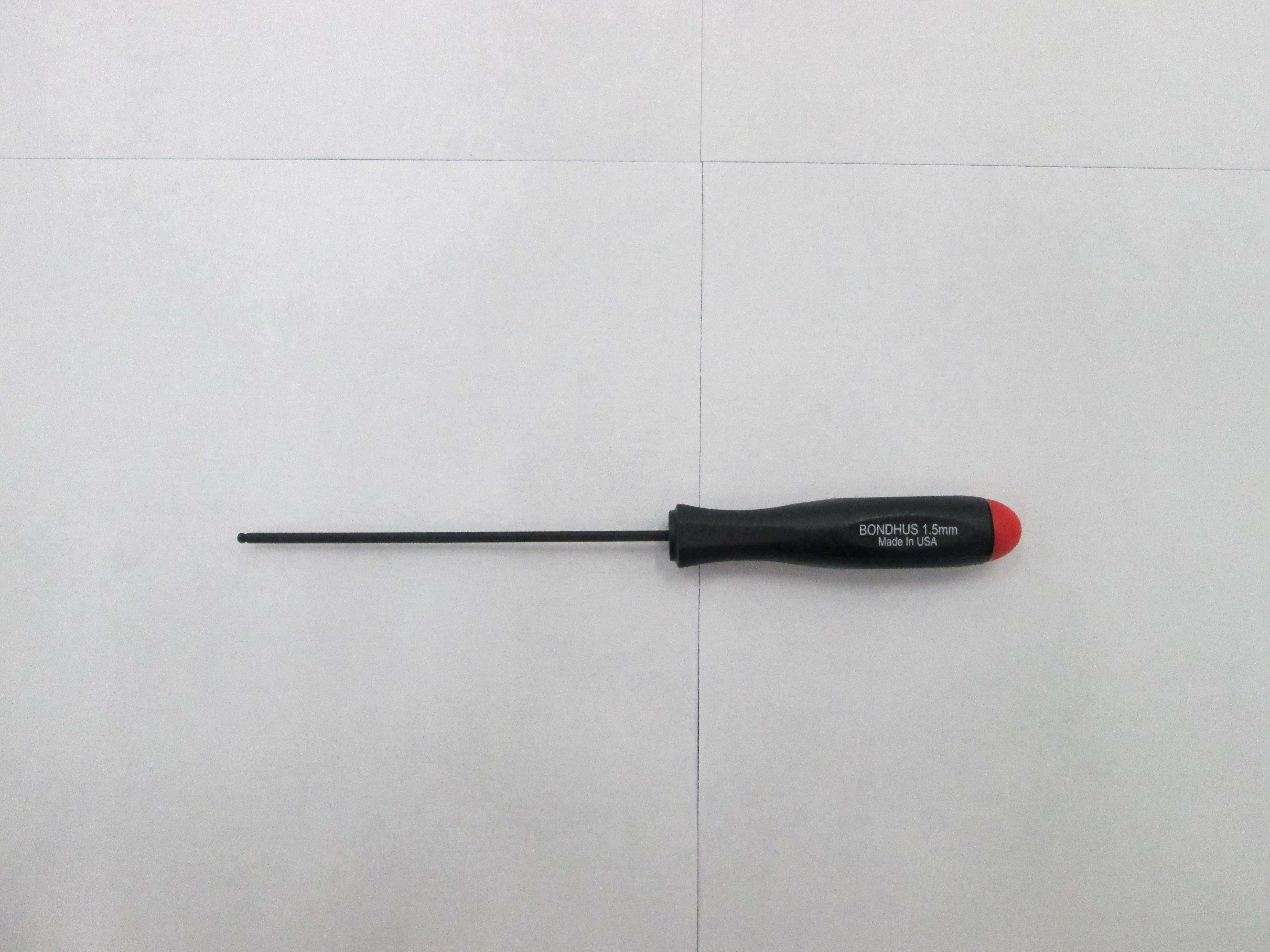
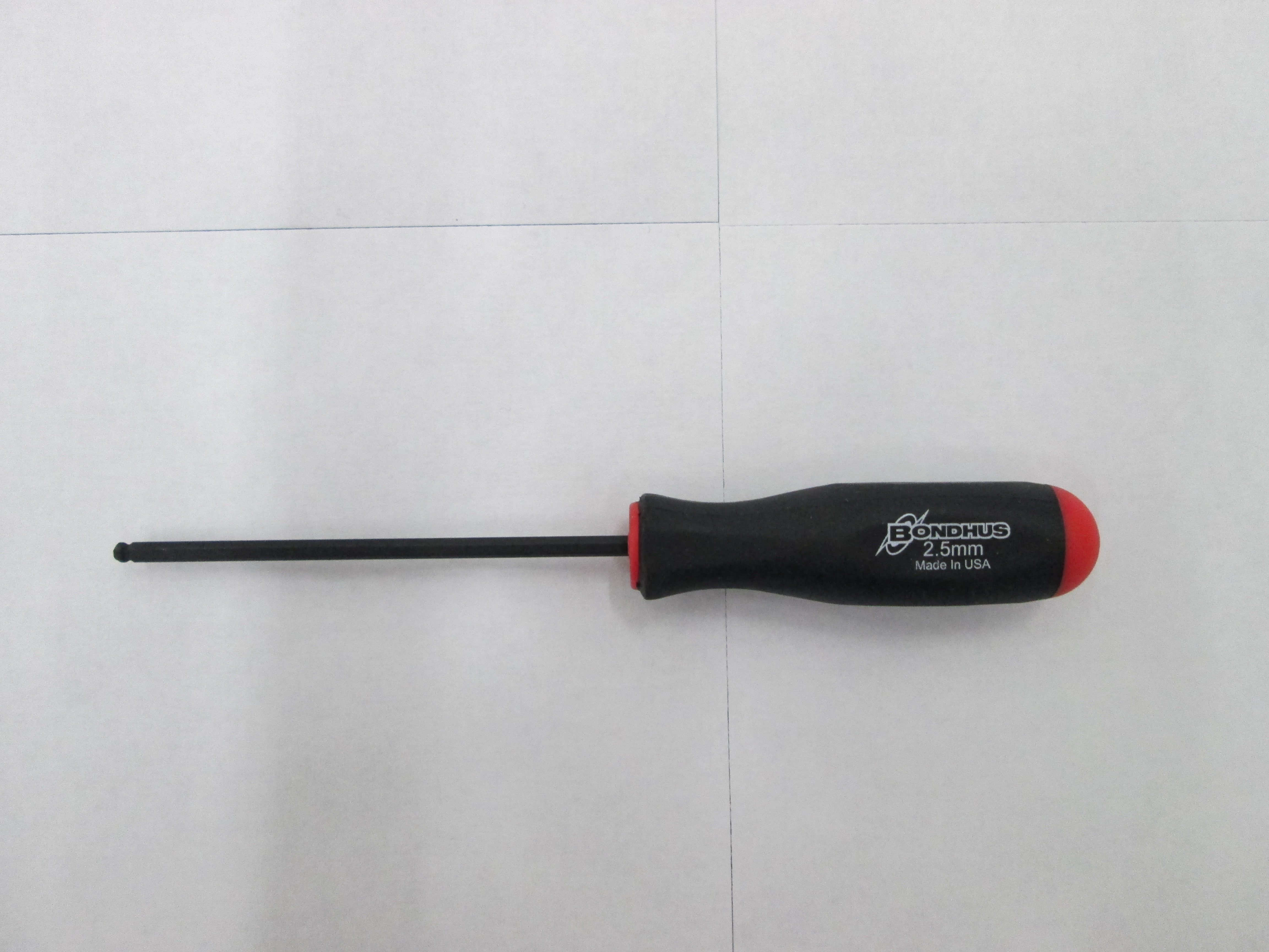
Tools:

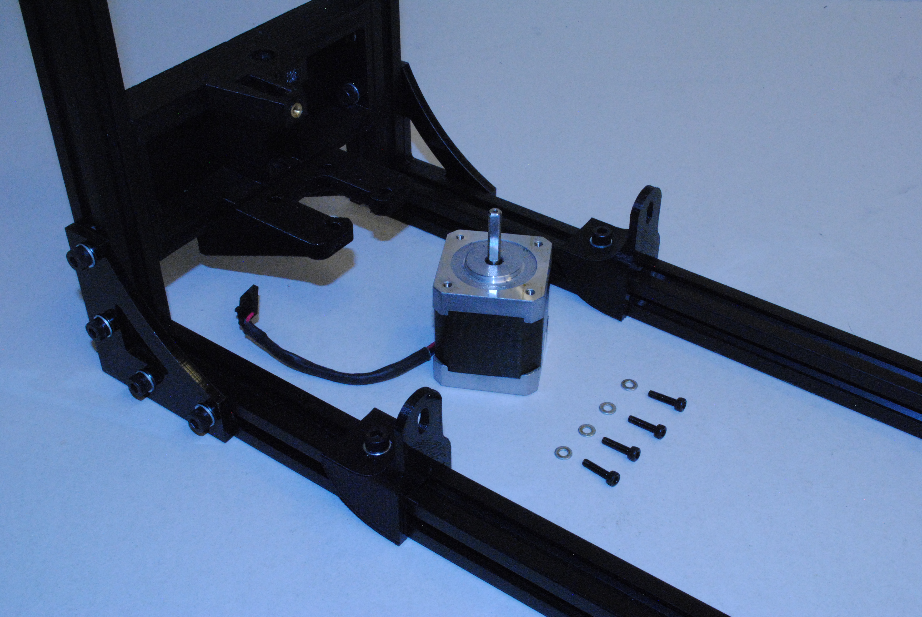
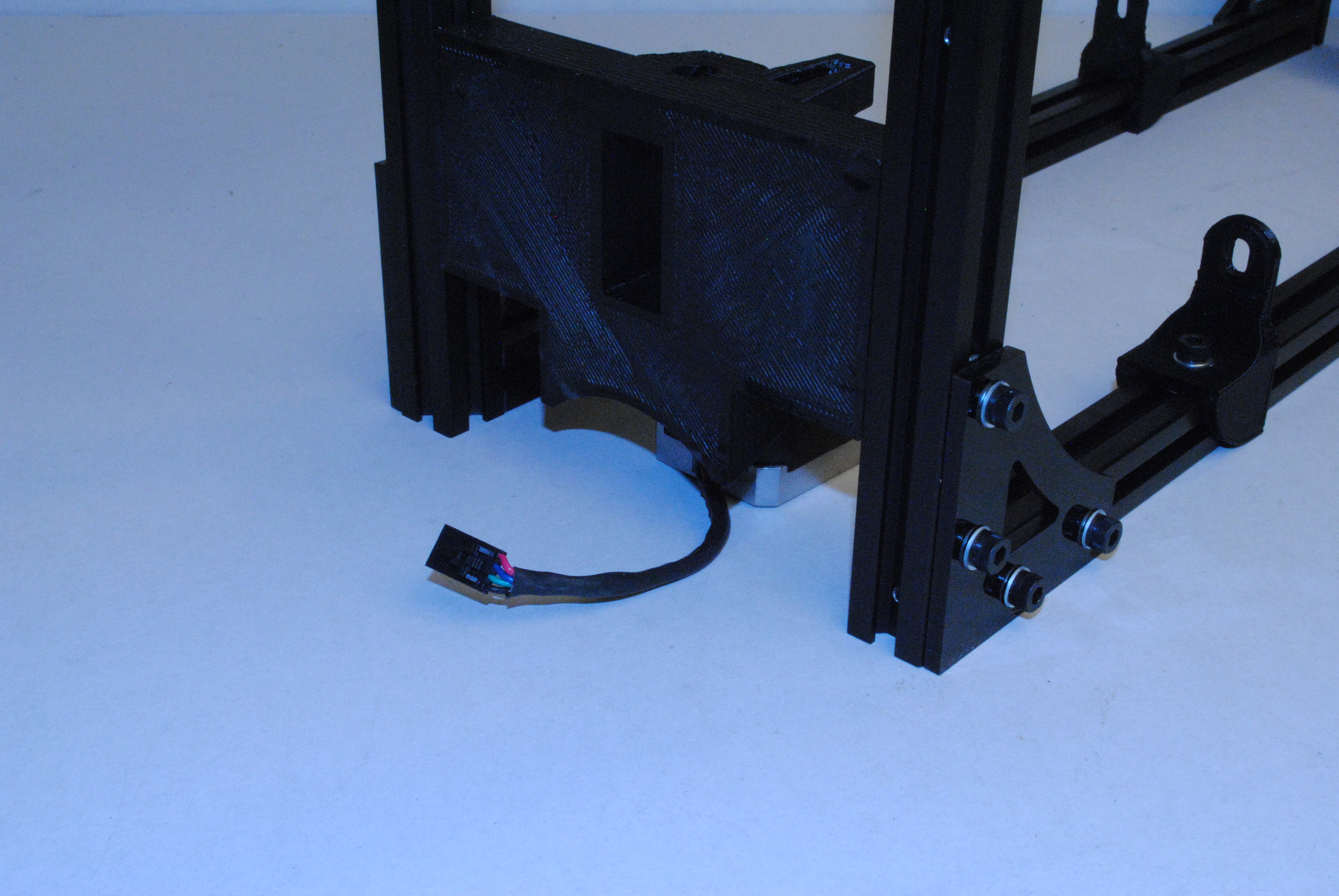
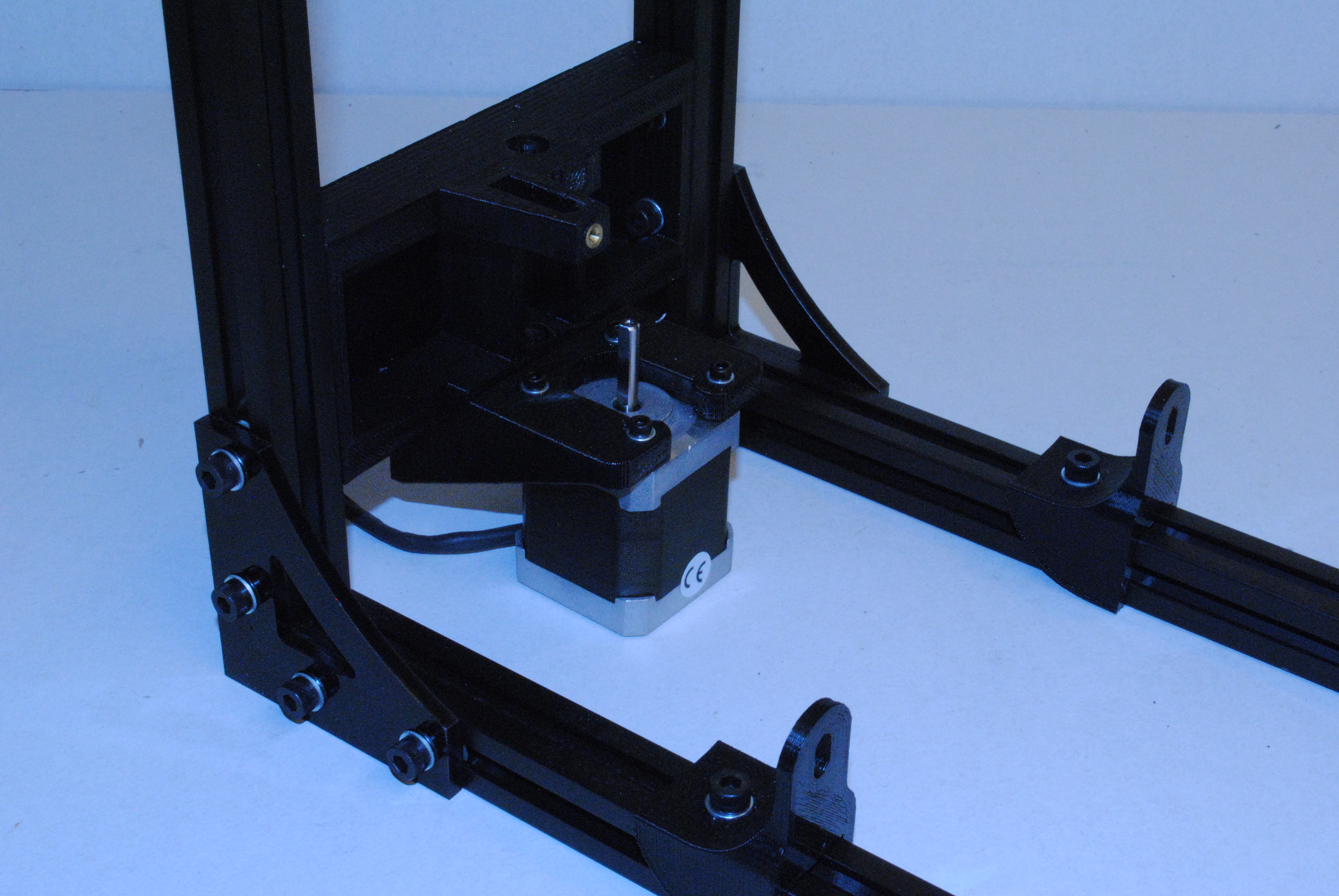
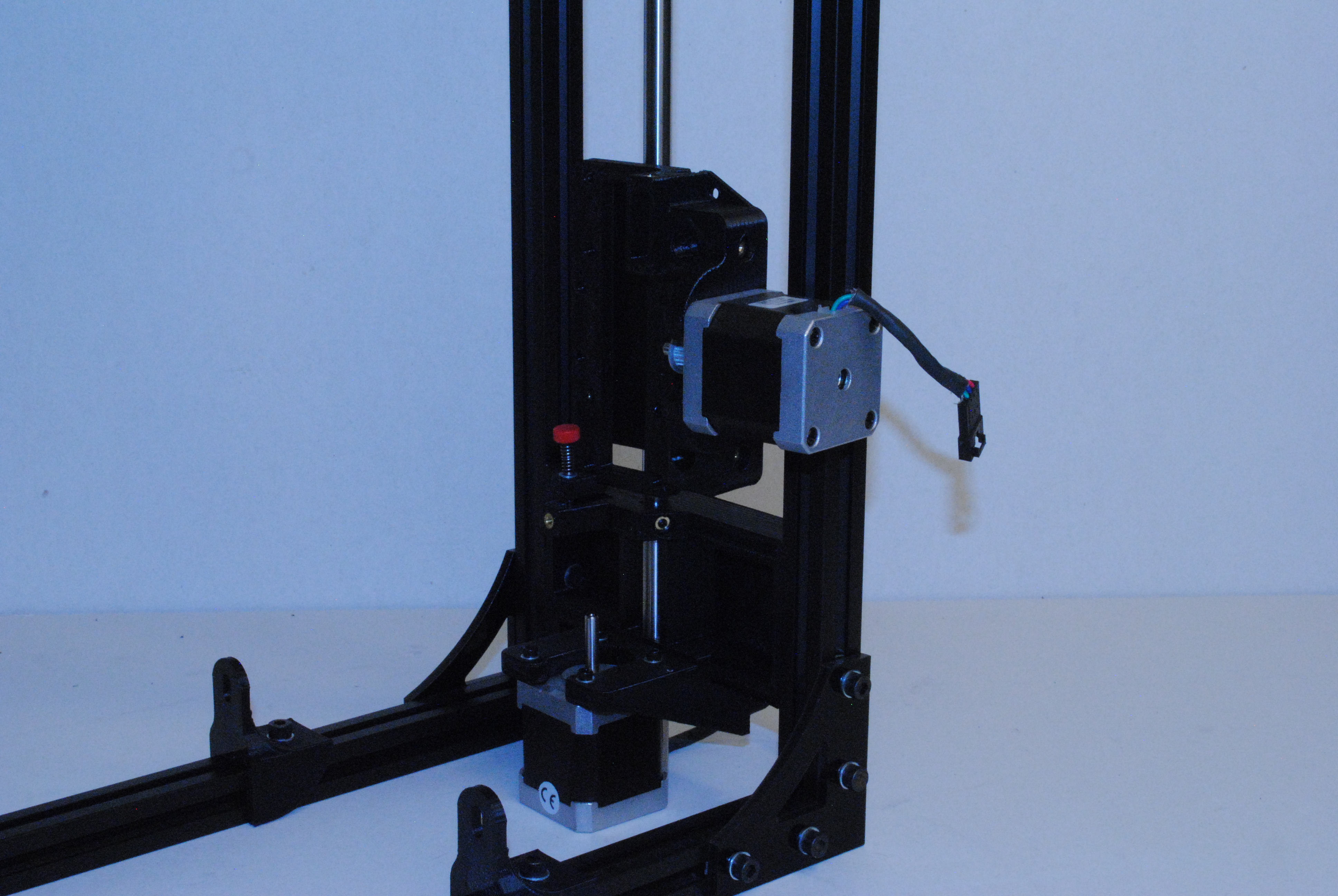
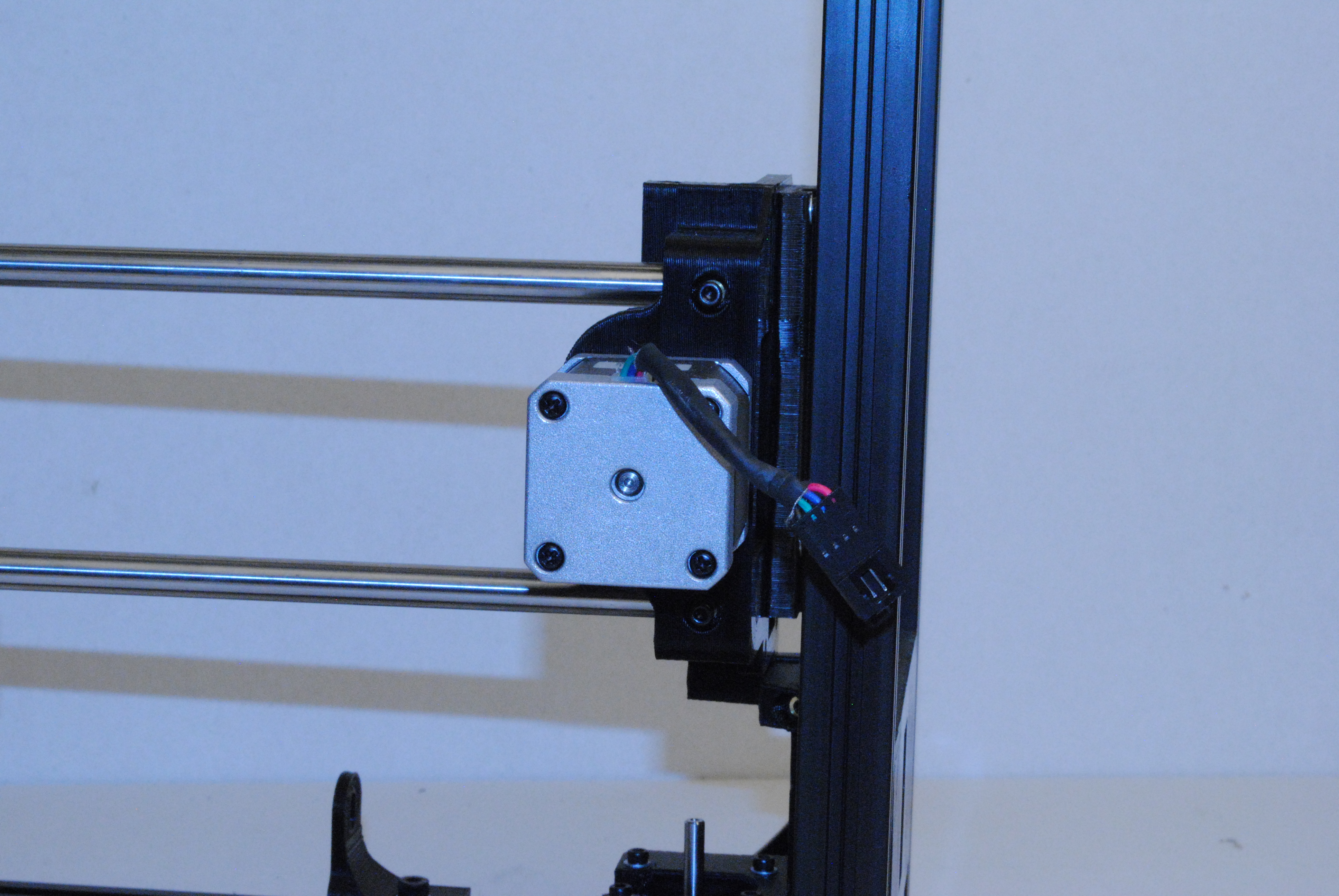
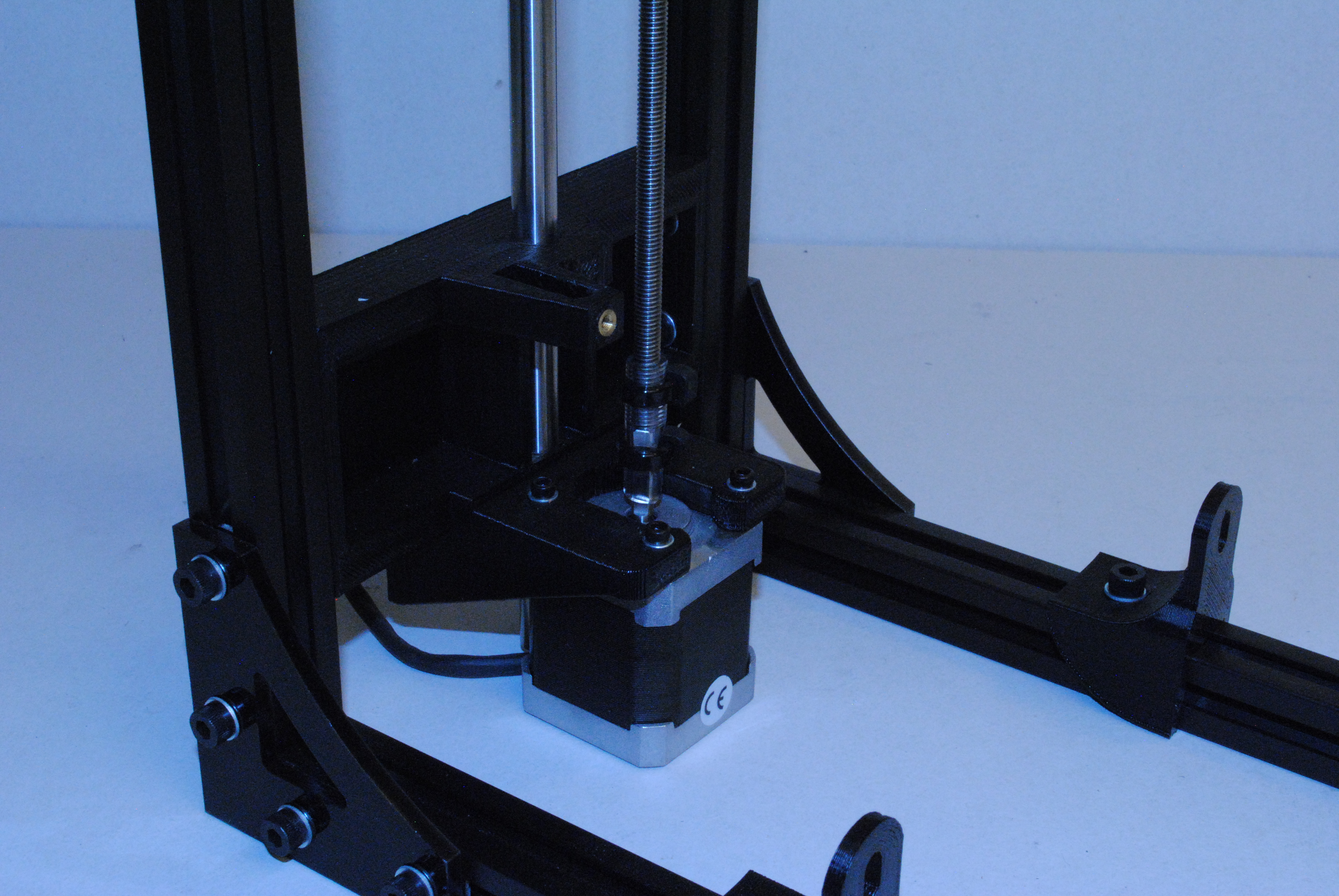
Install a Motor -2 using 4x M3 x 12 SHCS and M3 washers.
Take note of wire orientation.

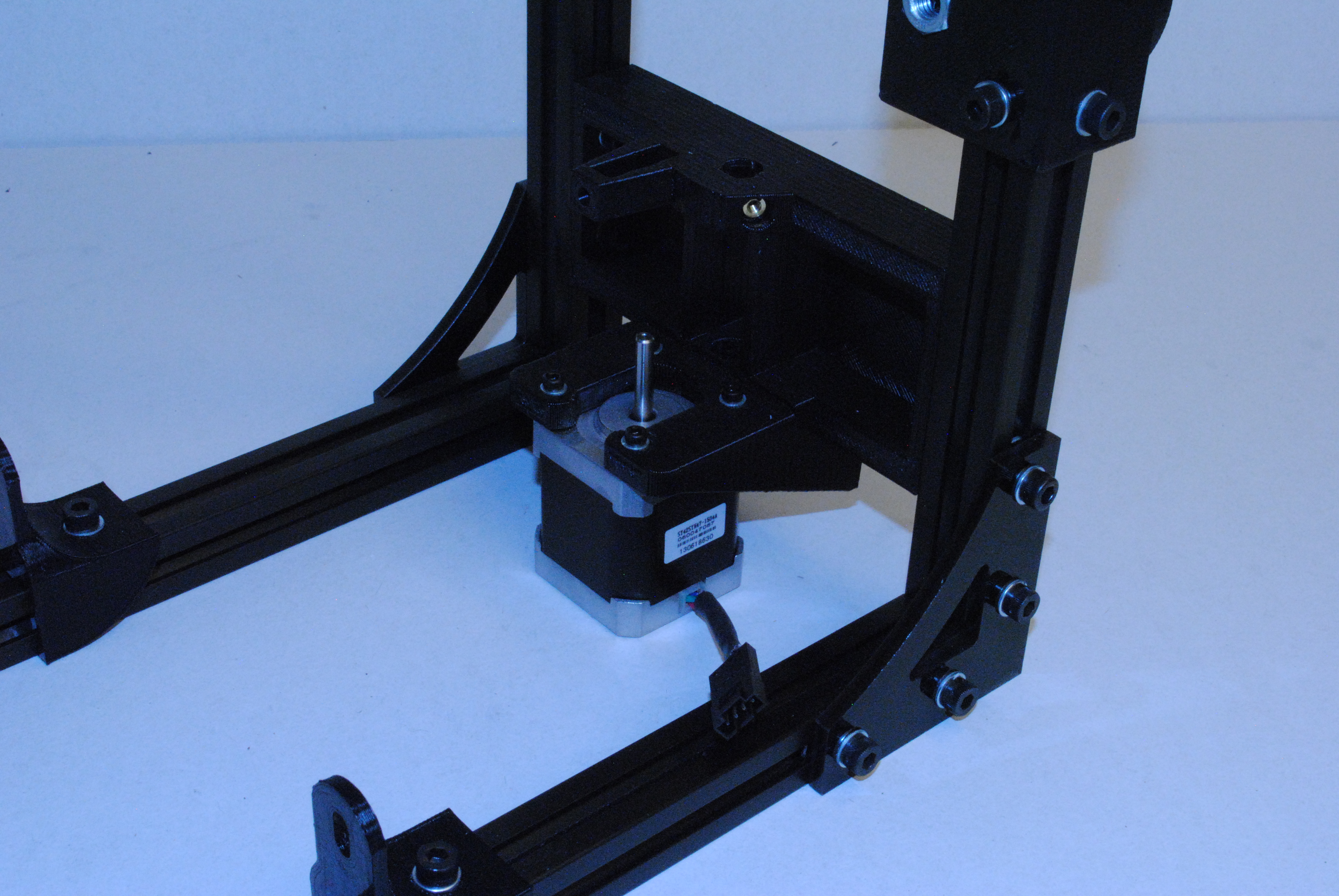
Install a Motor -1 using 4x M3 x 12 SHCS and M3 washers.
Take note of wire orientation.
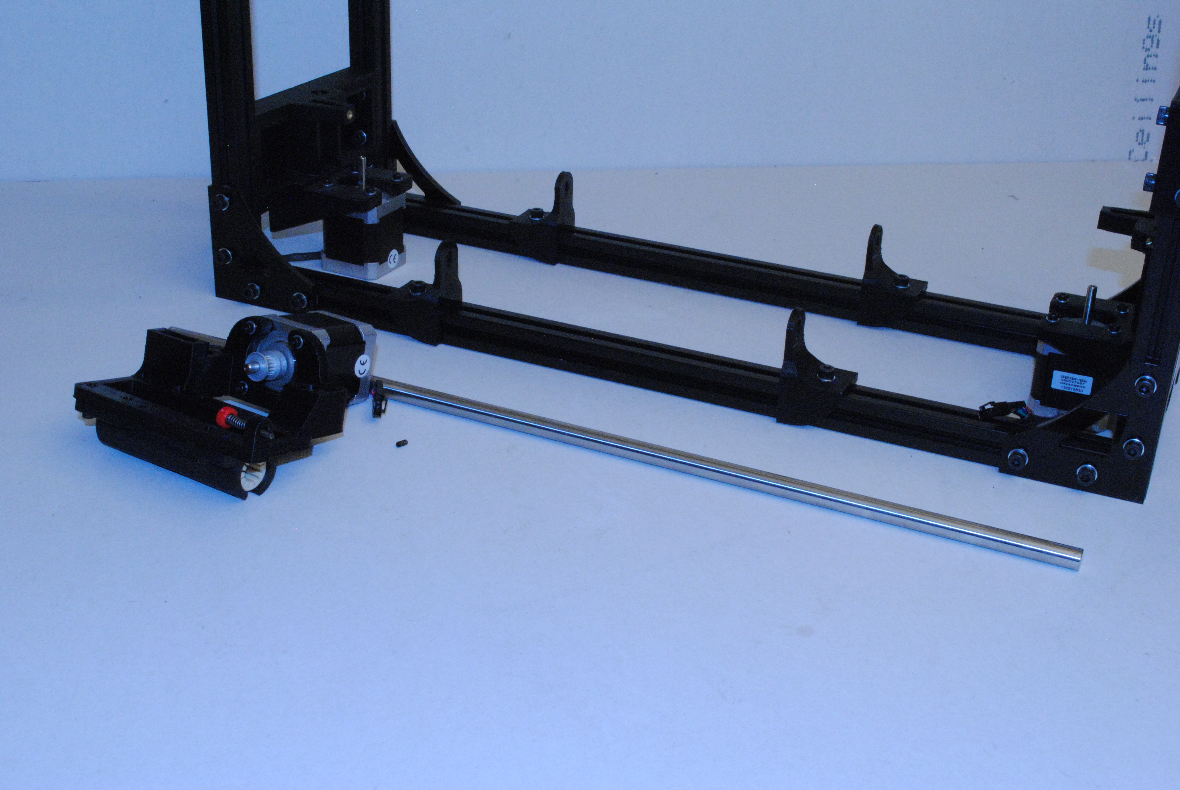
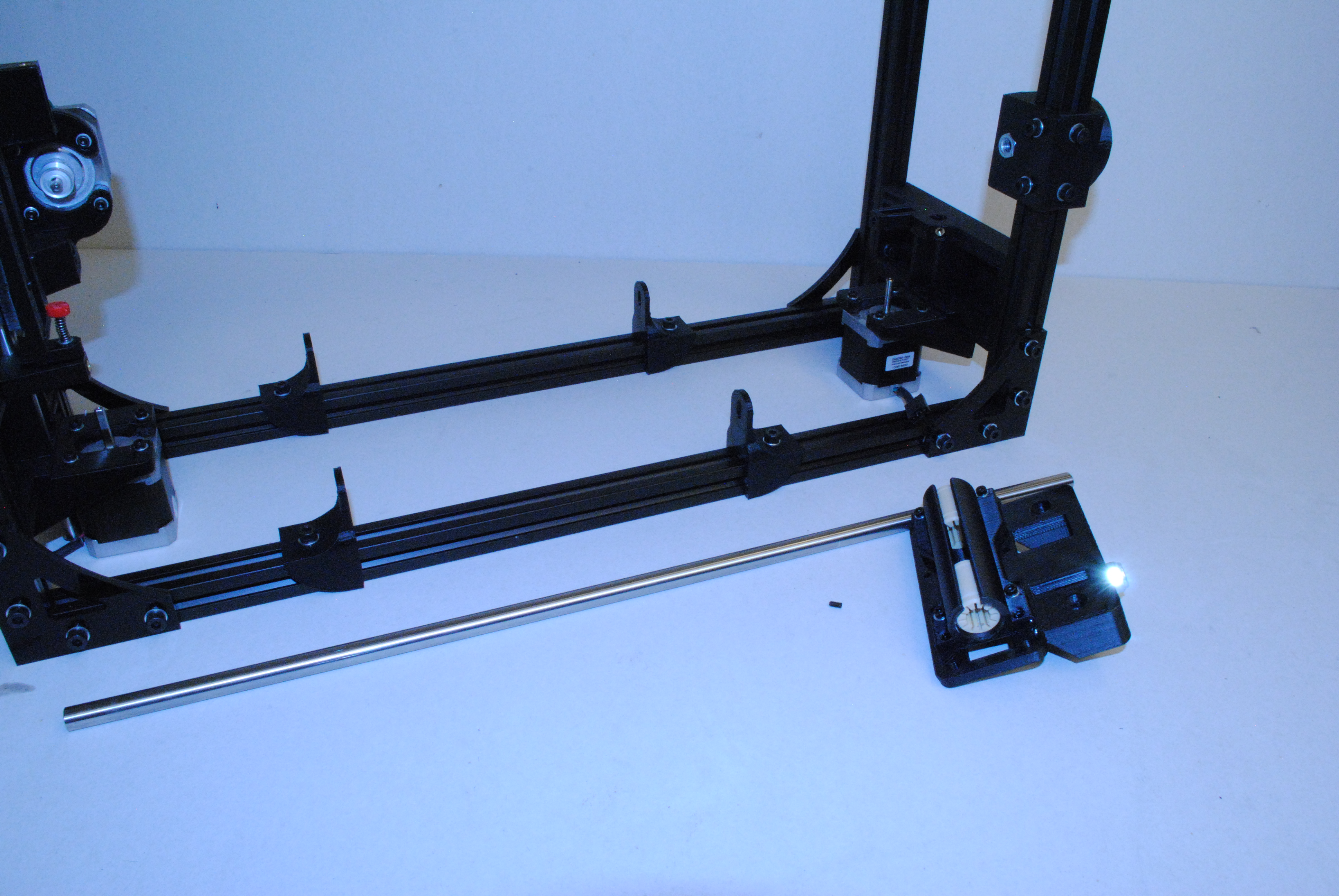
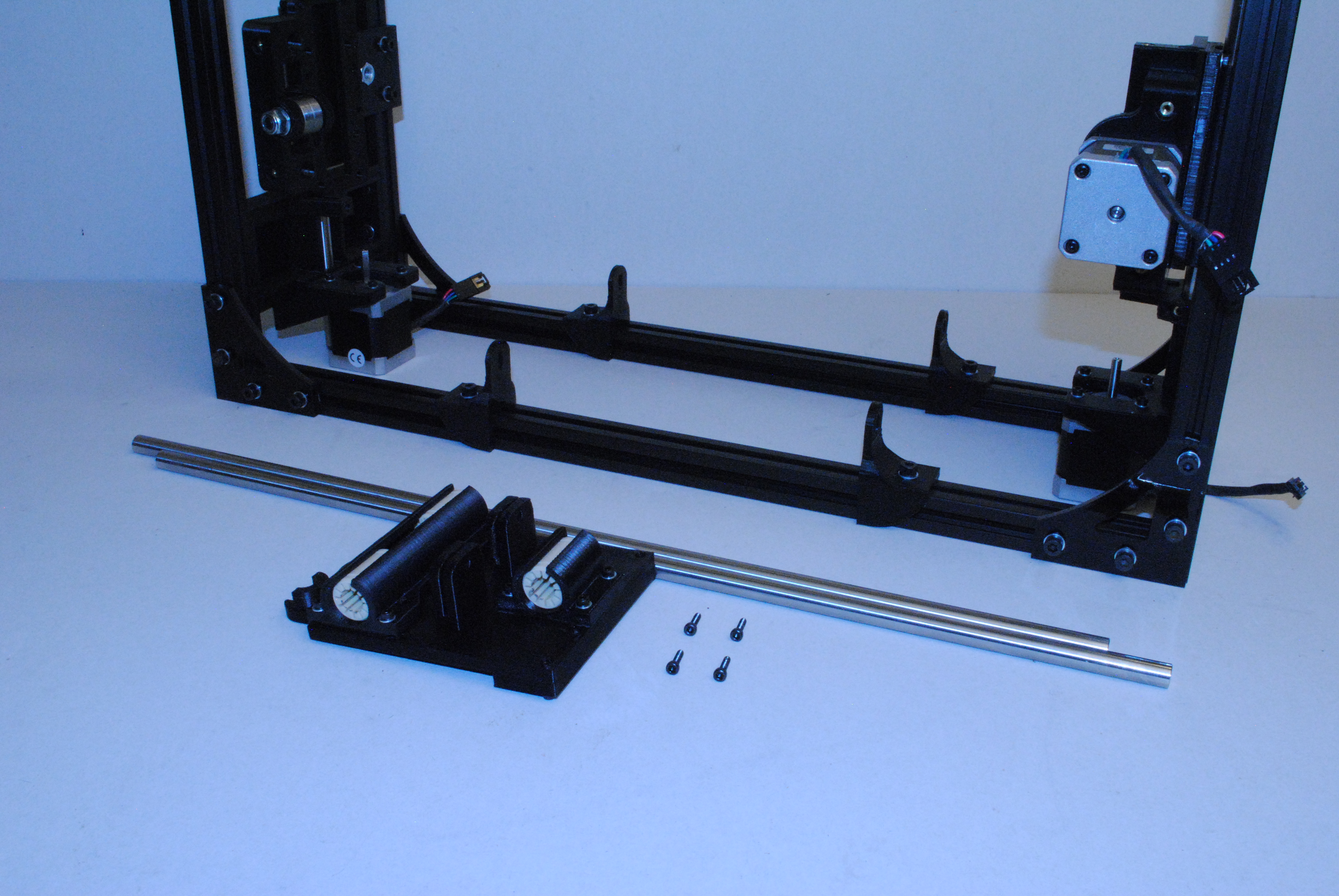
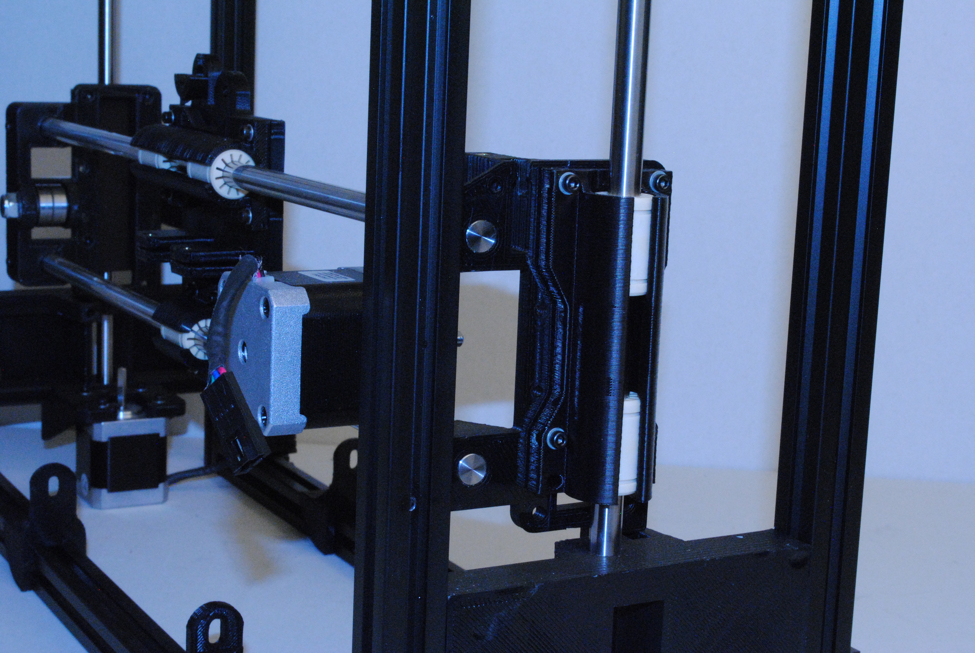
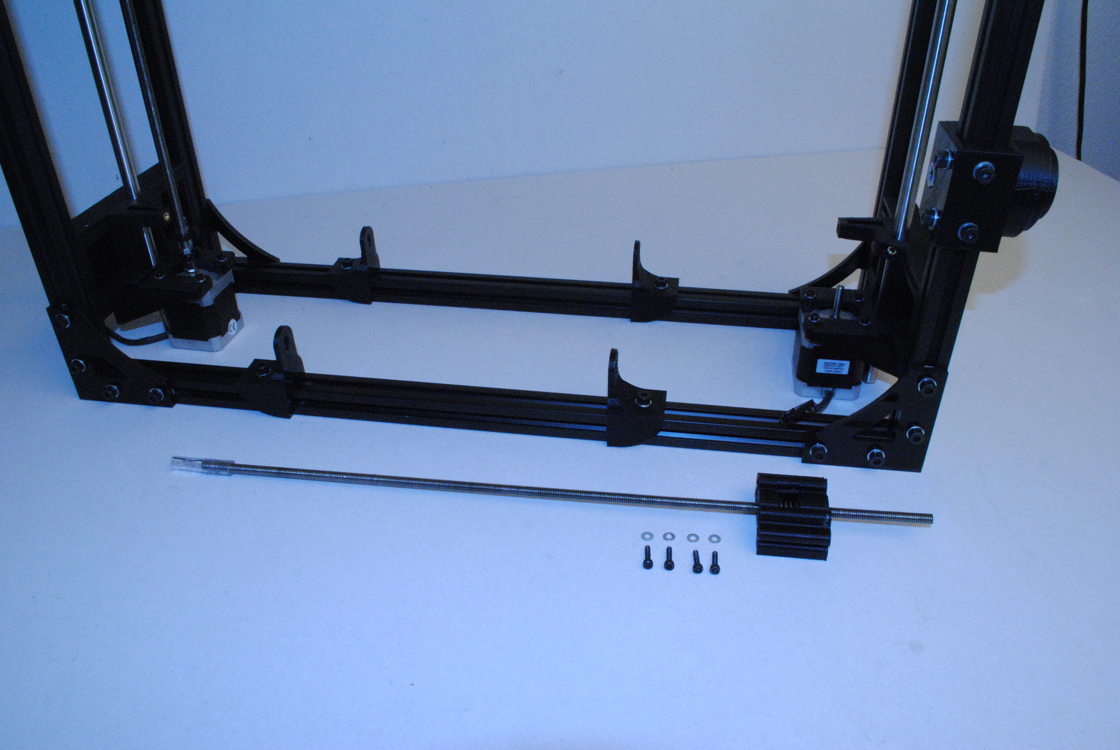
Slide a 10mm smooth rod up through the bottom of the left Z motor mount.
Once you get it started, put the X end motor onto the 10mm rod.
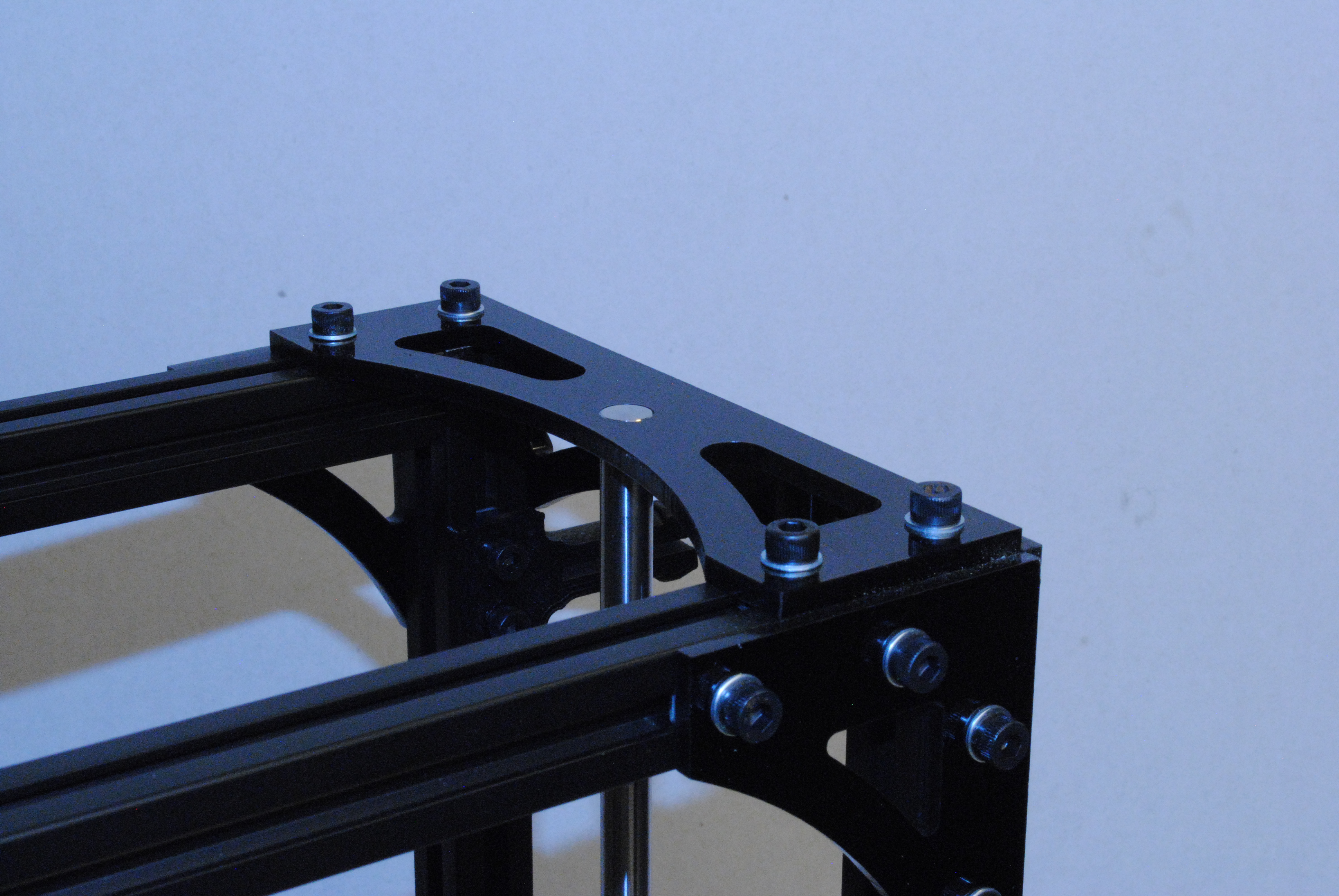
Slide the rod in until the end is flush with the top of the Z top flat plate.
Use a M3 x 6 set screw to secure the rod in place.

Slide a 10mm smooth rod up through the bottom of the right Z motor mount.
Once you get it started, put the X end idler onto the 10mm rod.
Slide the rod in until the end is flush with the top of the Z top flat plate.
Use a M3 x 6 set screw to secure the rod in place.

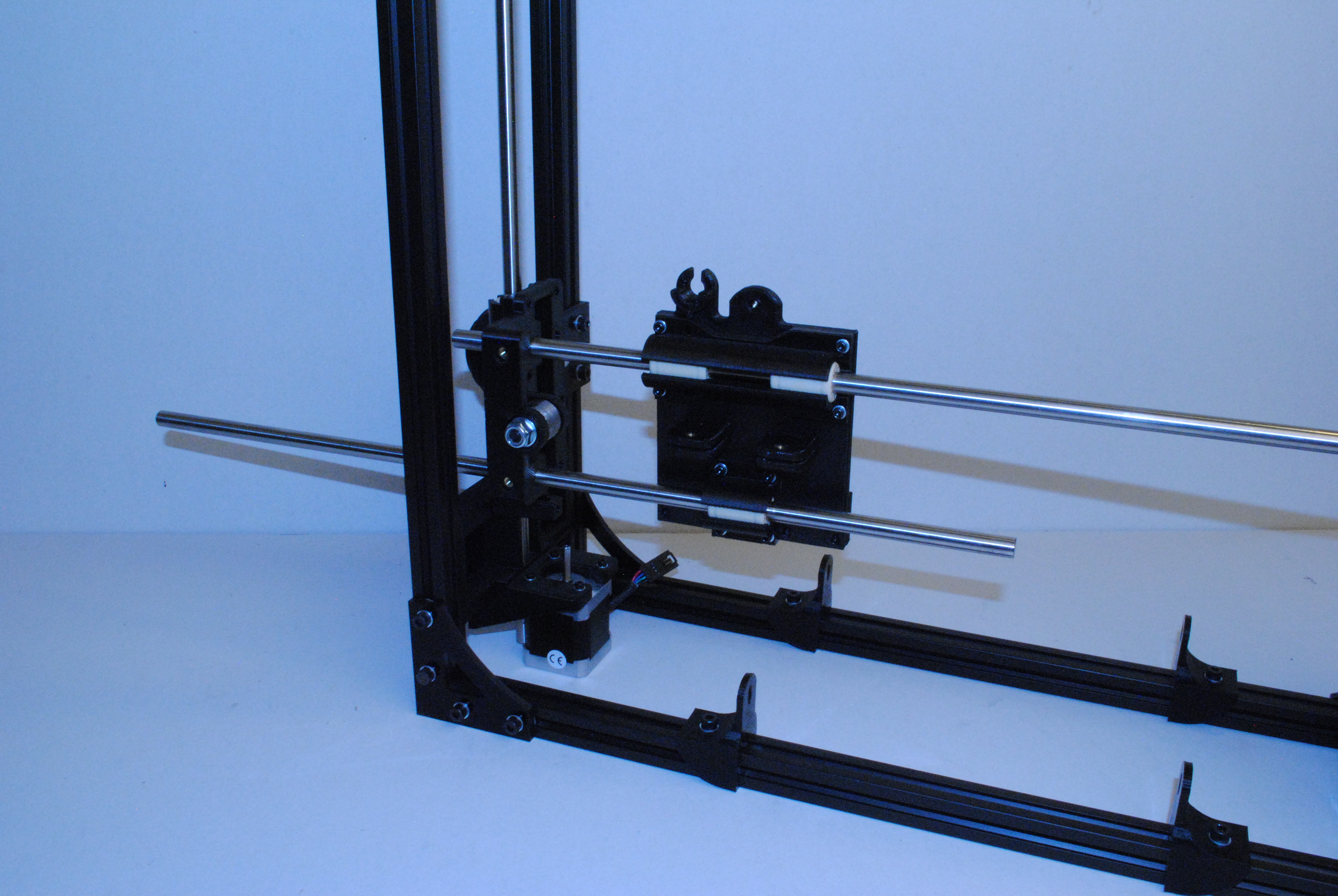
Slide a 10mm rod through one of the two holes in the X end idler.
Once its through far enough, put the X carriage on the rod.
Finish sliding the 10mm rod through until it's also inserted into the X end motor.
The rod will be flush with the outside of the X end motor.
Repeat with the second 10mm rod in the second set of holes.
Using 4 M3 x 12 SHCS, lock the rods in place at the X ends.
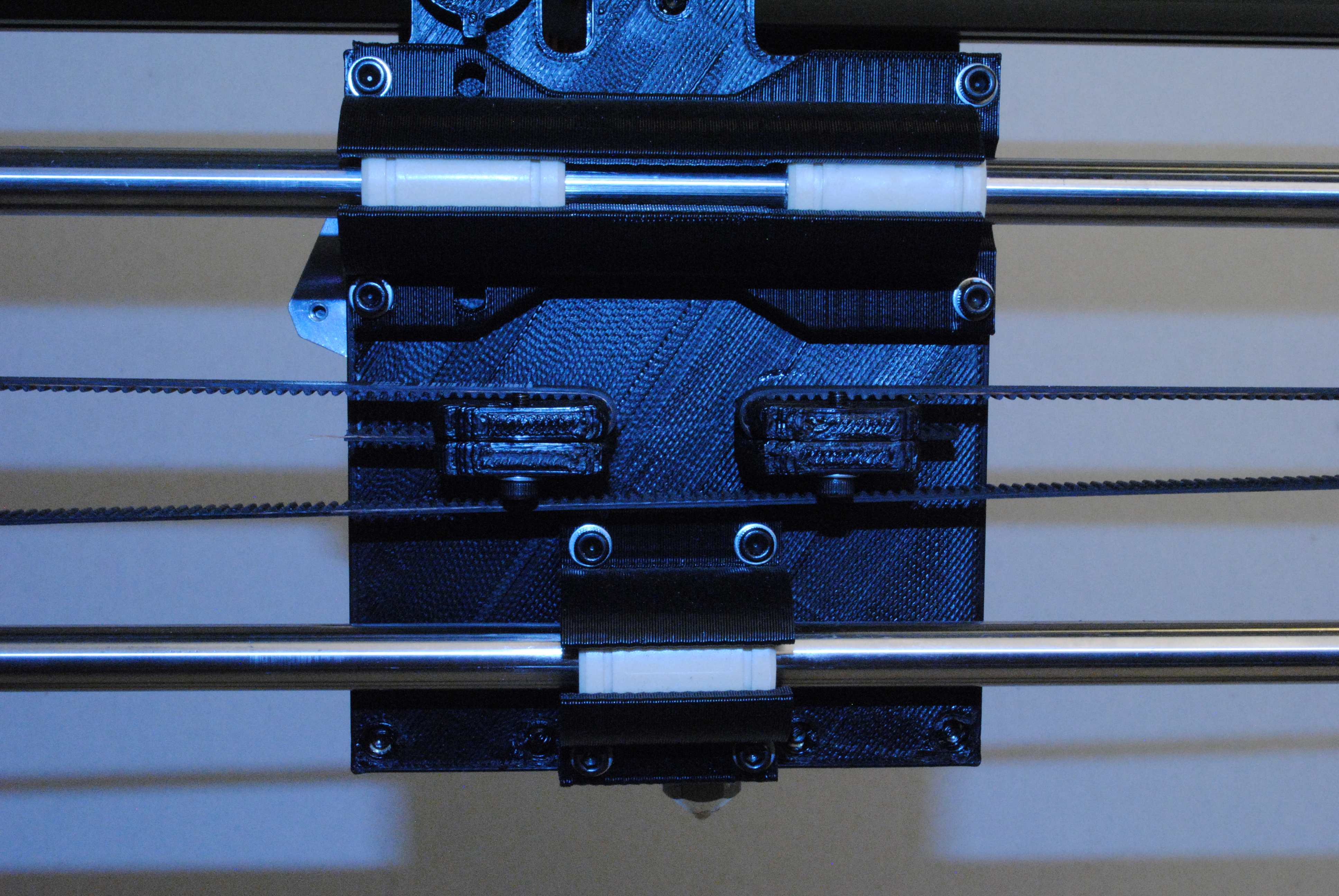
Tighten the bolts holding the bearing holders on the X carriage making sure it still slides freely back and forth.
Tighten the bolts holding the double bearing holders on the X ends at this point as well.

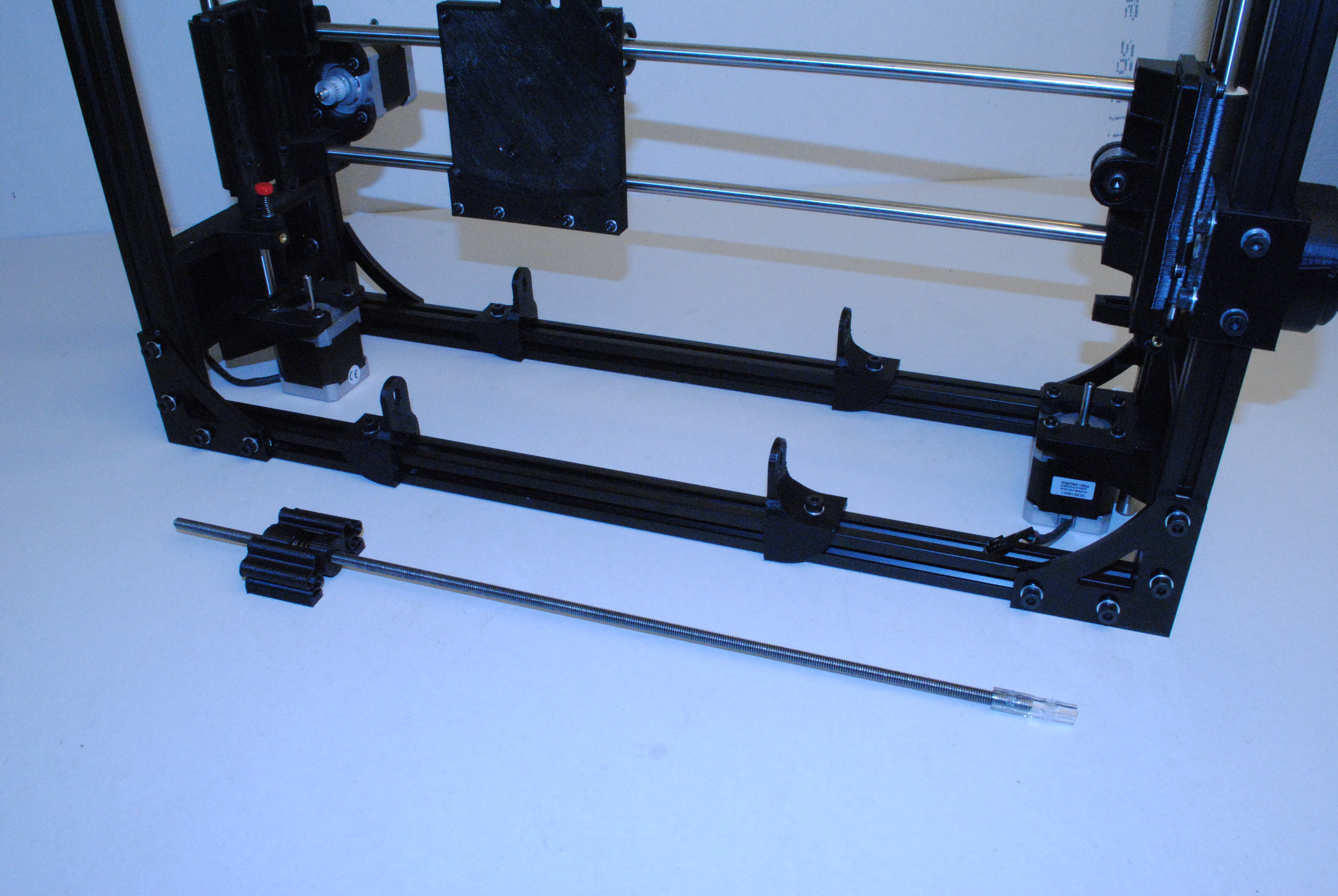
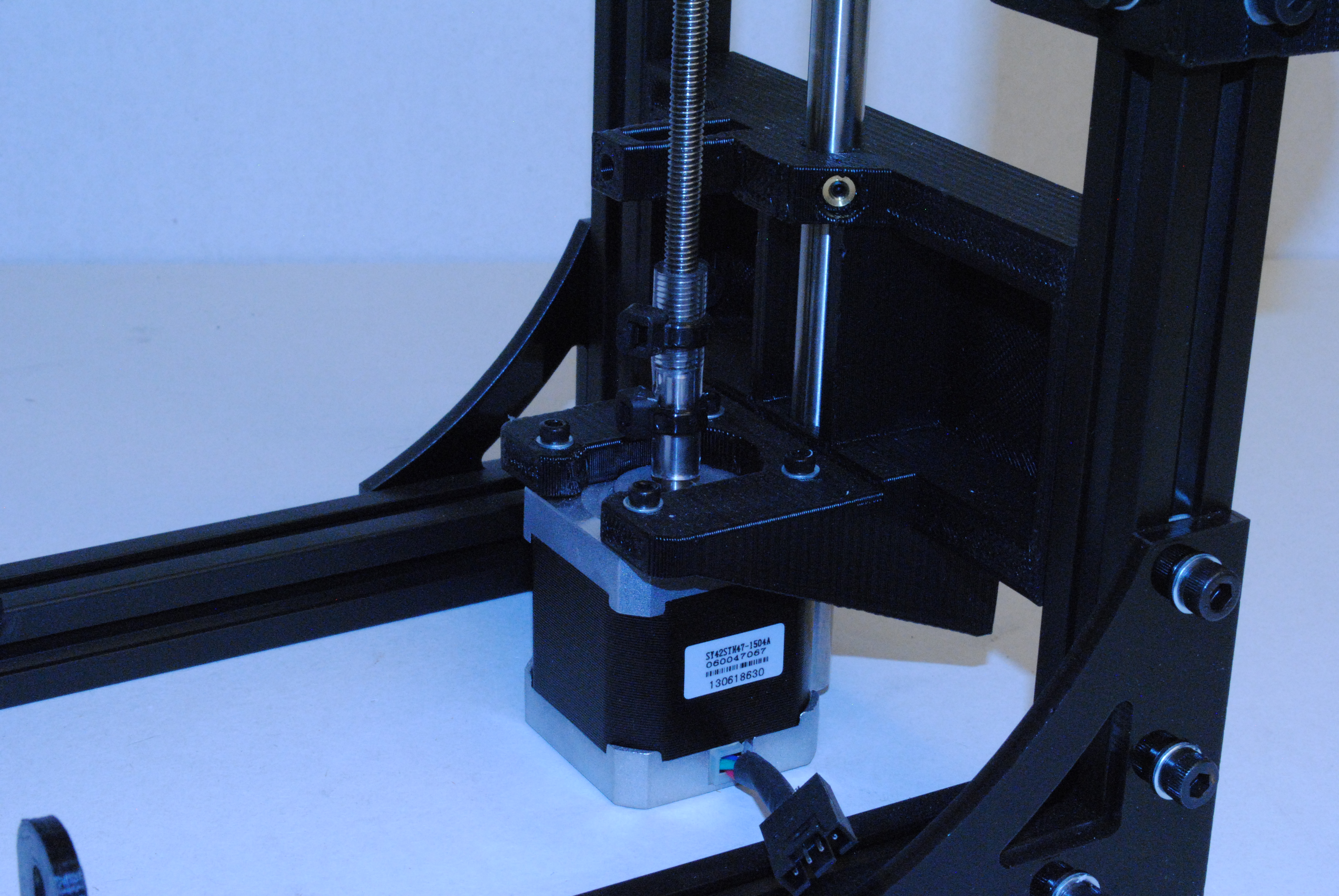
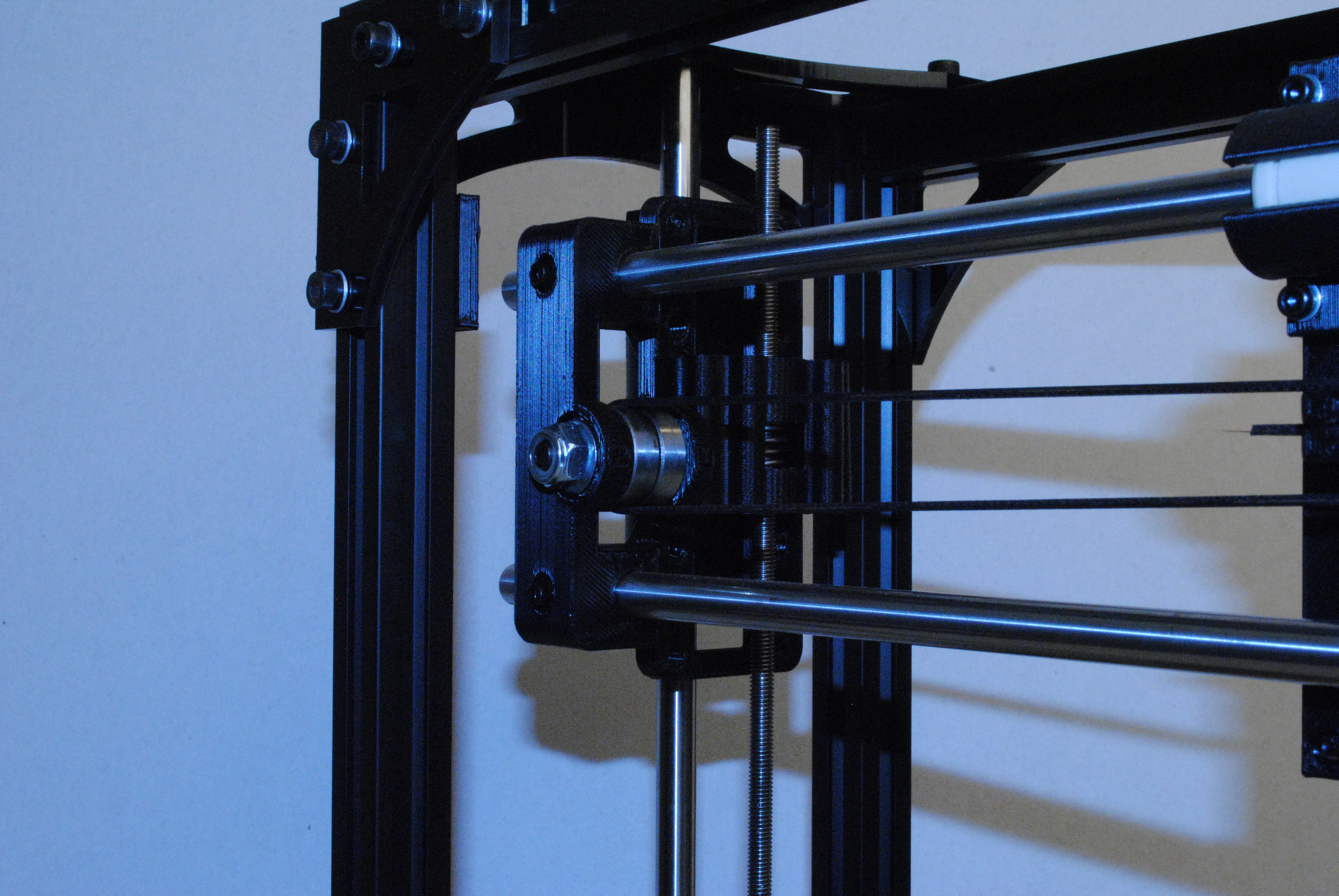
Push the end of the coupler tube down onto the Motor shaft.
Lift up the X/Z axis until you can bolt the Z nut holder to the X end motor.
Using 4x M3 x 12 SHCS and M3 Washers, attach the Z nut holder to the X end motor.
Install large zip ties on the end of the drive rod and on the motor shaft as shown.
The zip does must be tight enough that you can't pull the drive rod off vertically.

Push the end of the coupler tube down onto the Motor shaft.
Adjust the height of the Z nut holder by spinning it to get it close in height to the X end idler.
Using 4x M3 x 12 SHCS and M3 Washers, attach the Z nut holder to the X end idler.
Install large zip ties on the end of the drive rod and on the motor shaft as shown.
The zip must be tight enough that you can't pull the drive rod off vertically.

Take the print head assembly and seat the bottom of it down into the X carriage assembly.
Using a M3 x 12 SHCS and M3 washer, bolt the top of the print head assembly to the X carriage.

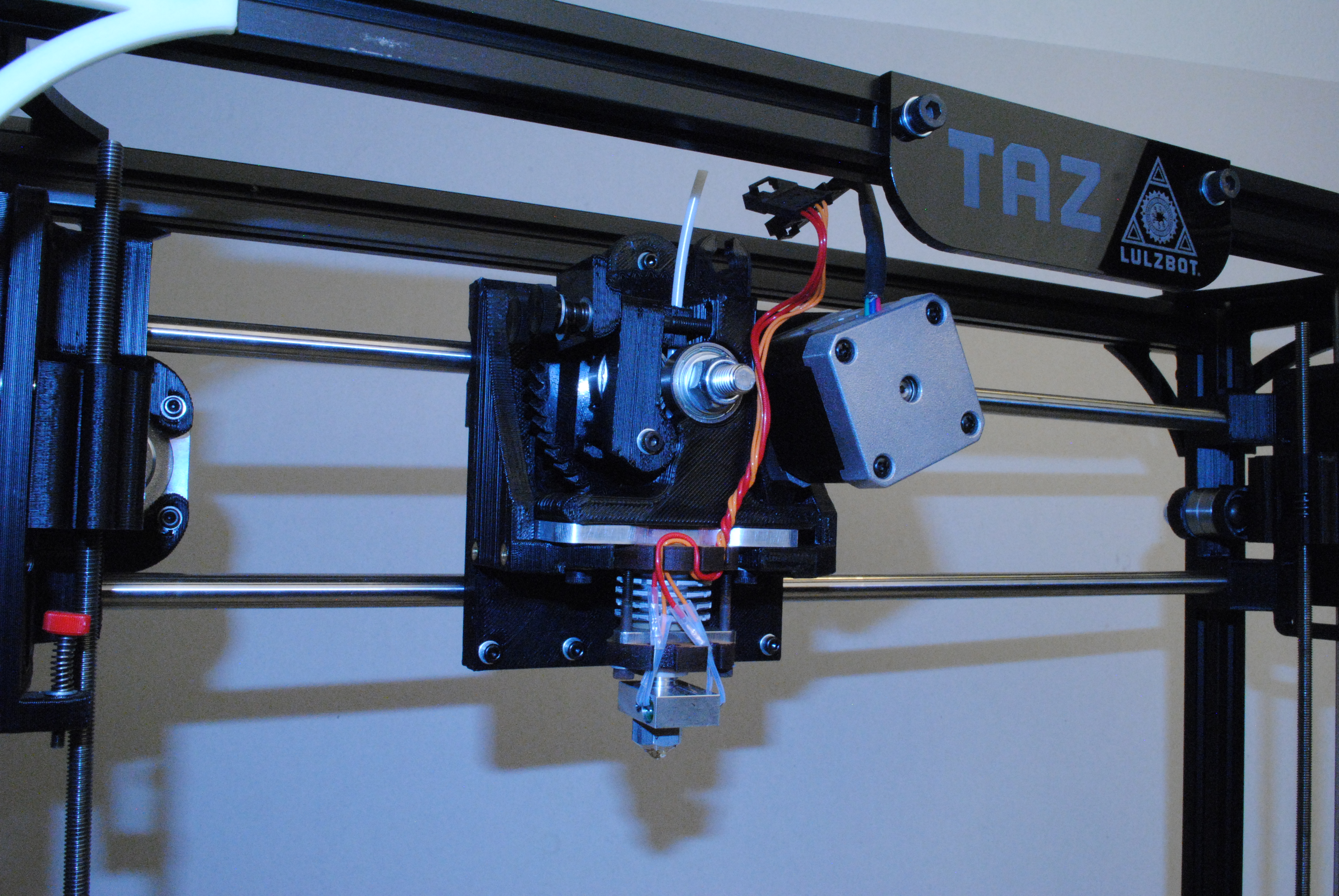
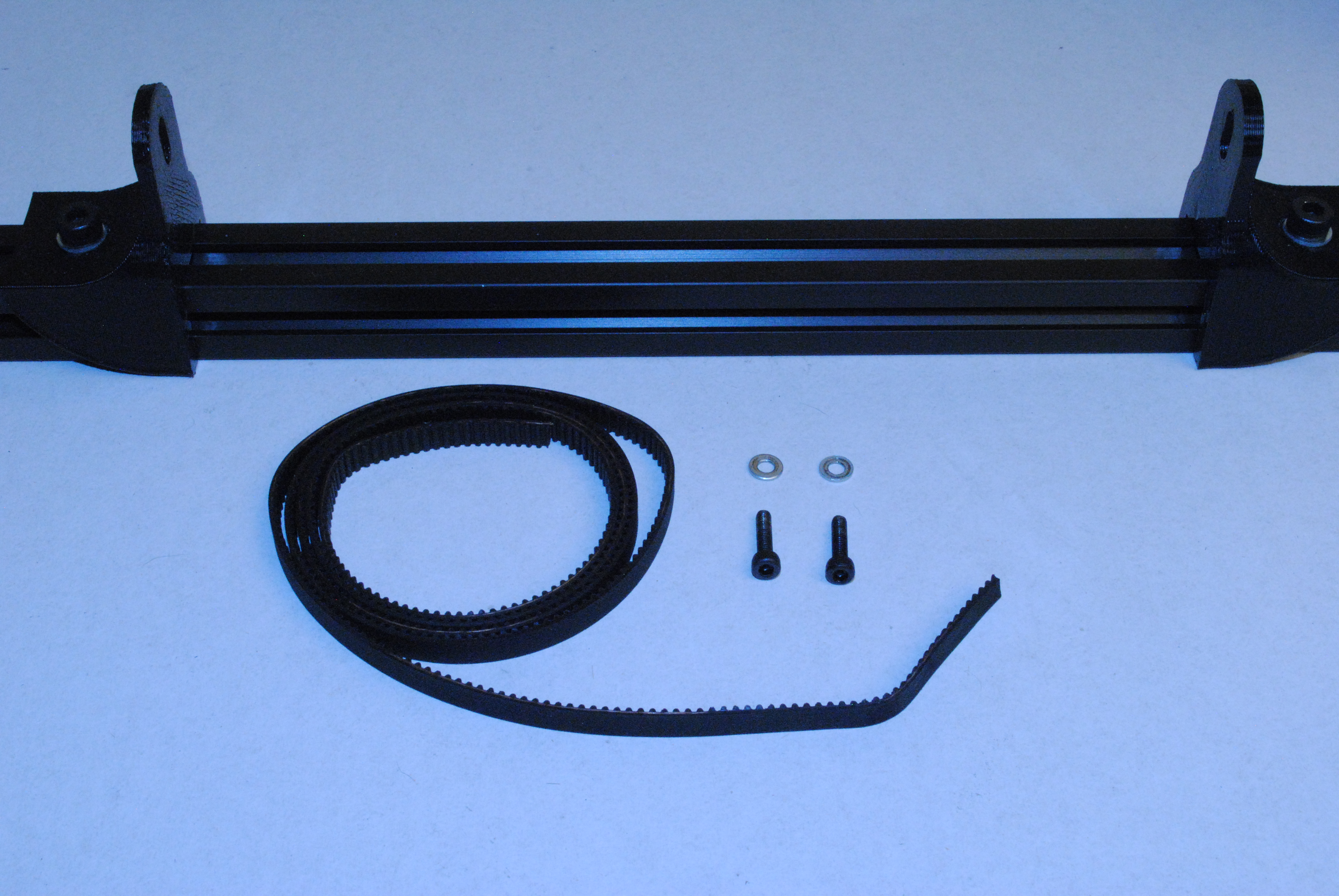
First cut the belt with a side cutters.
Route one end through the X carriage as shown and clamp down with a M3 x 12 SHCS and M3 Washer.
Next route the belt around the pulley on the X end motor and the bearings on the X end idler.
Finish routing the belt back at the X carriage.
Pull tight and clamp down with a M3 x 12 SHCS and M3 Washer.
Trim the ends of the belt so they do not interfere with the pulley or bearings.
Check for belt rubbing as you move the X carriage back and fourth. Adjust as necessary.

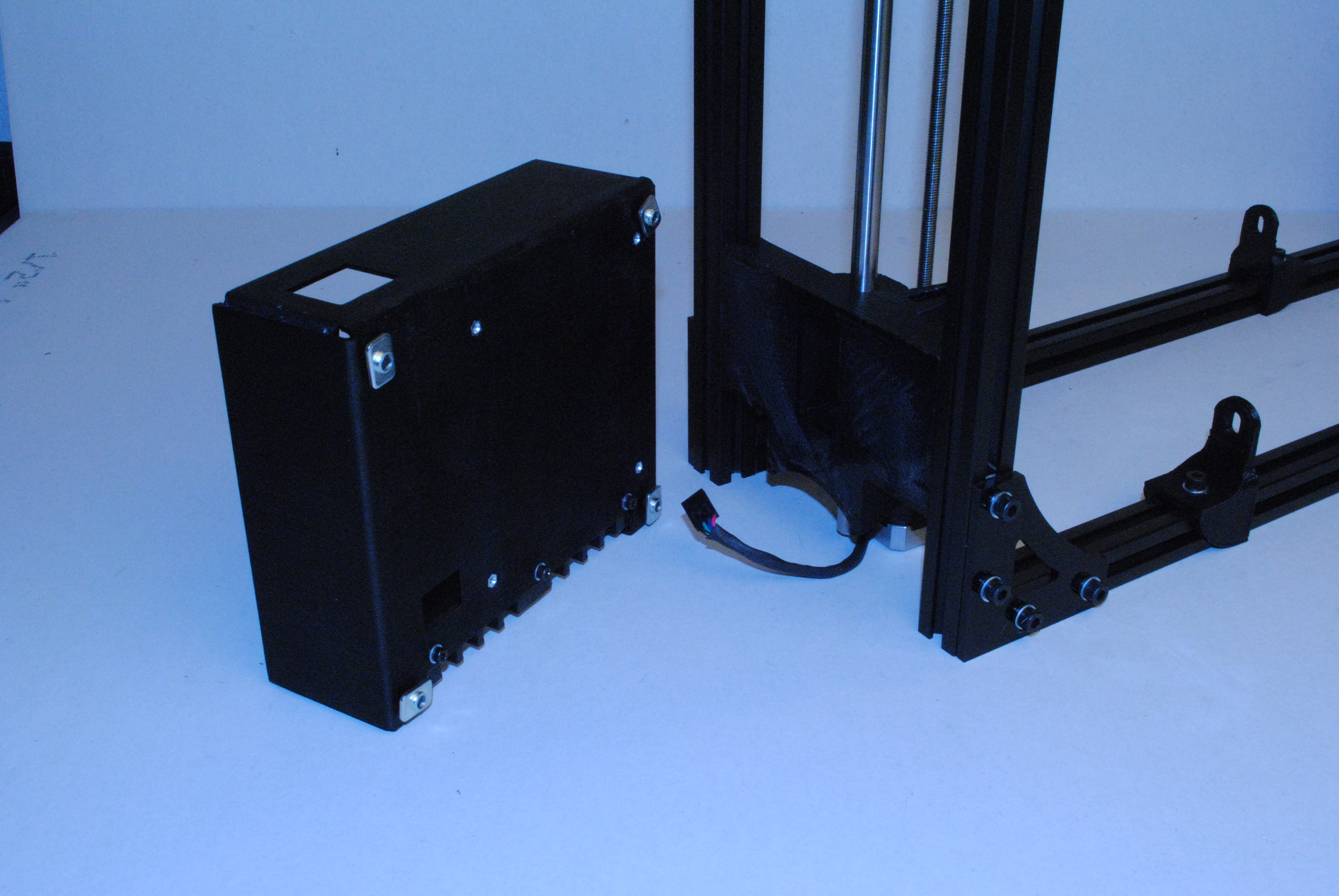
Using 4x M5 x 8 BHCS, M5 Washers and M5 T-nuts, attach the Electronics case assembly to the frame.
Set the bottom of the Electronics case flush with the bottom of the assembly.
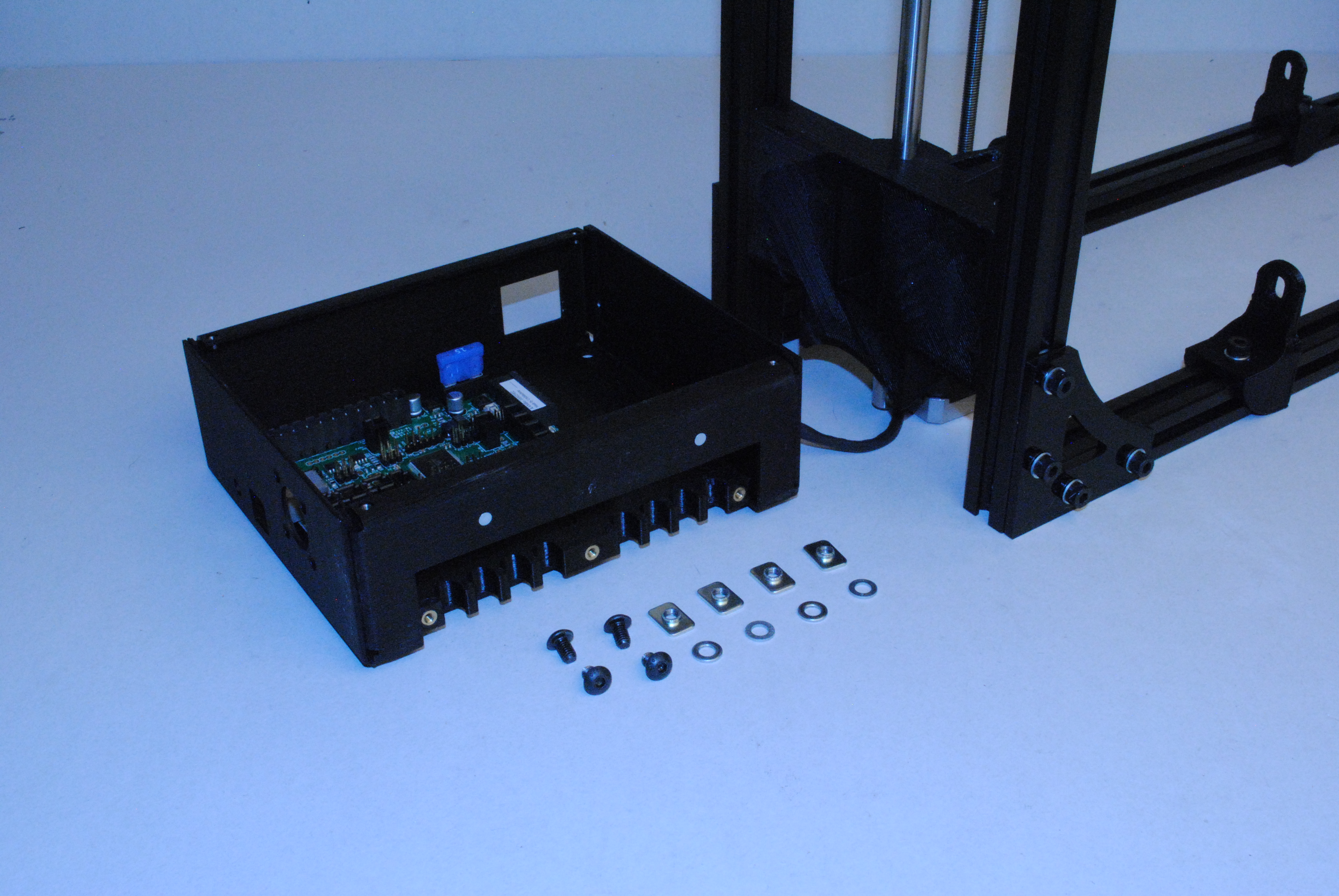

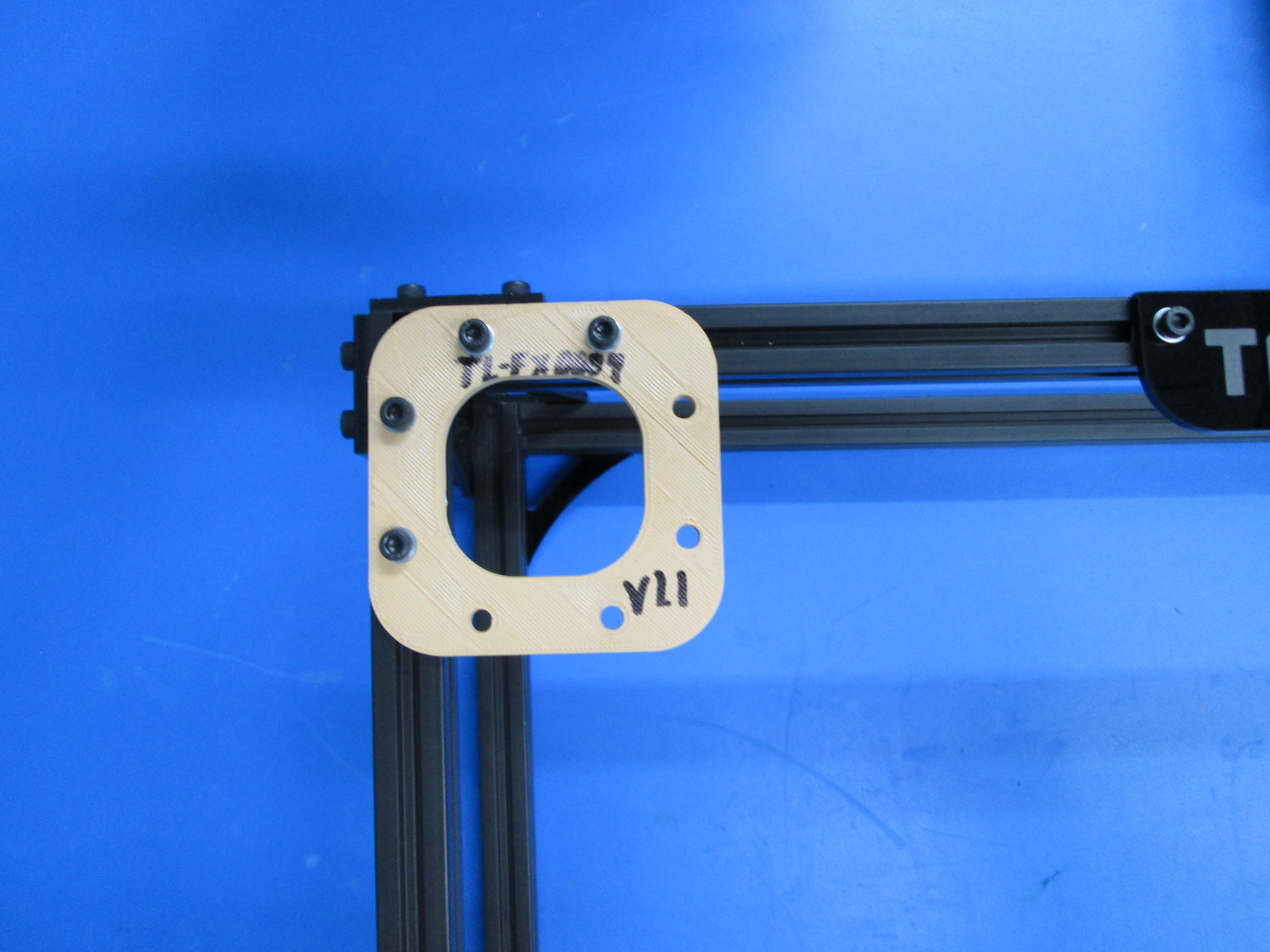
Remove the assembly fixture TL-FX9999 from the corner of the frame.
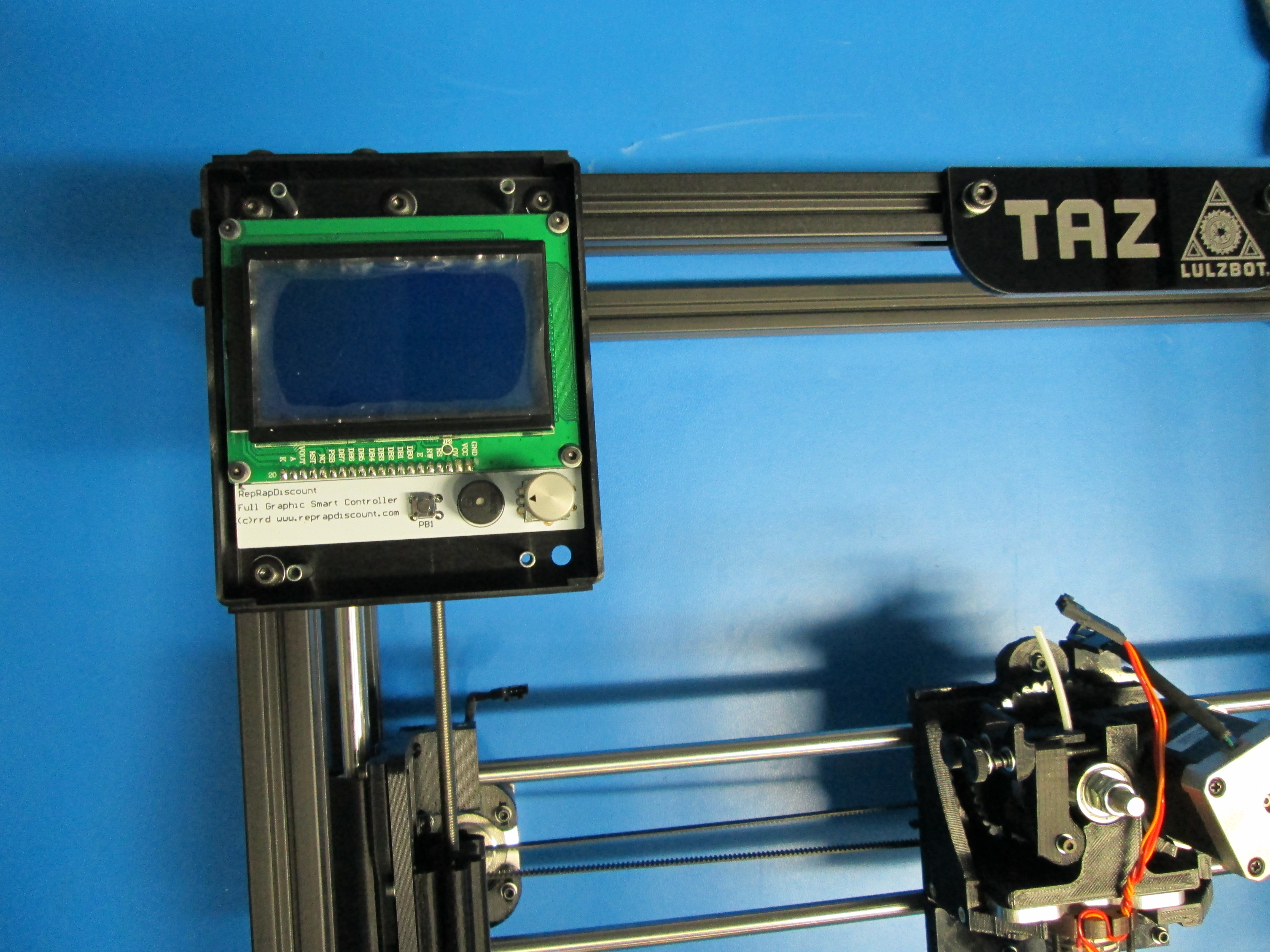
Using the already installed M5 T-nuts along with 4x M5 x 8 BHCS and M5 Washers, attach the LCD case assembly to the frame.
Set the edge and top of the LCD case flush with the outside of the frame.
Using 4x M3 x 12 SHCS and M3 Washers, attach the LCD cover.