Open HardwareAssembly Instructions
Guides for installation and assembly of the LulzBot line of products made by FAME 3D LLC.
Guides for installation and assembly of the LulzBot line of products made by FAME 3D LLC.
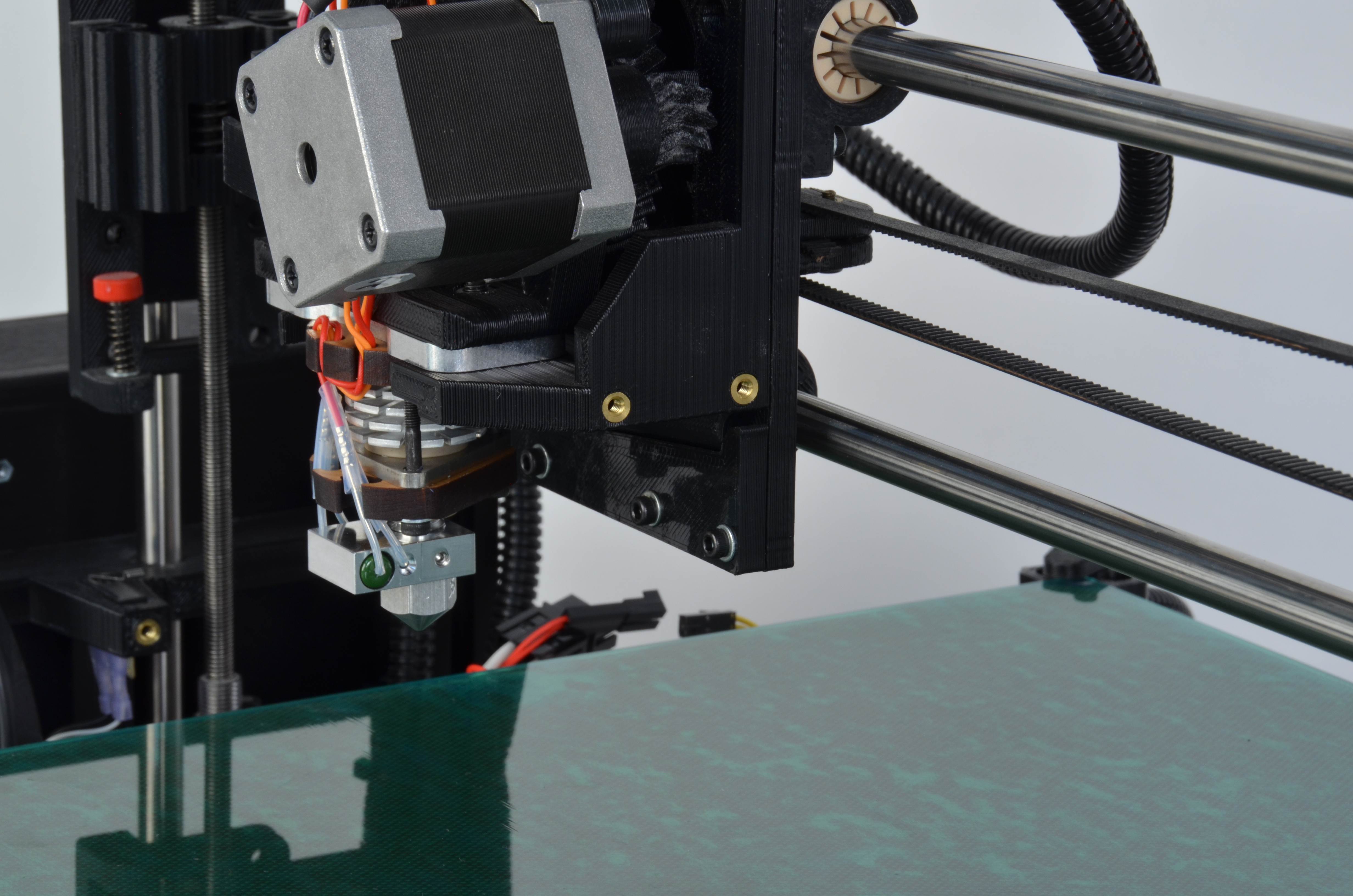
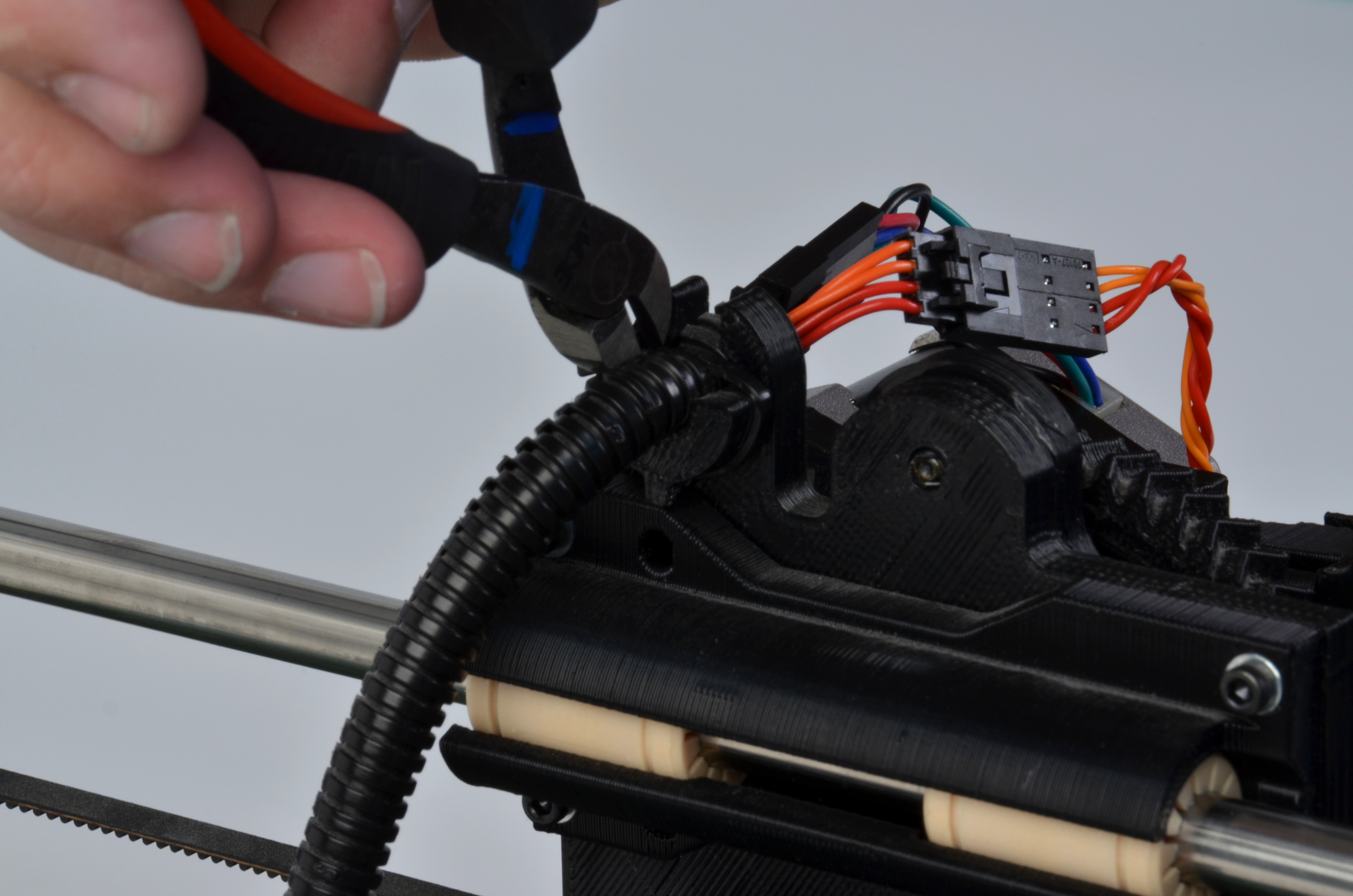
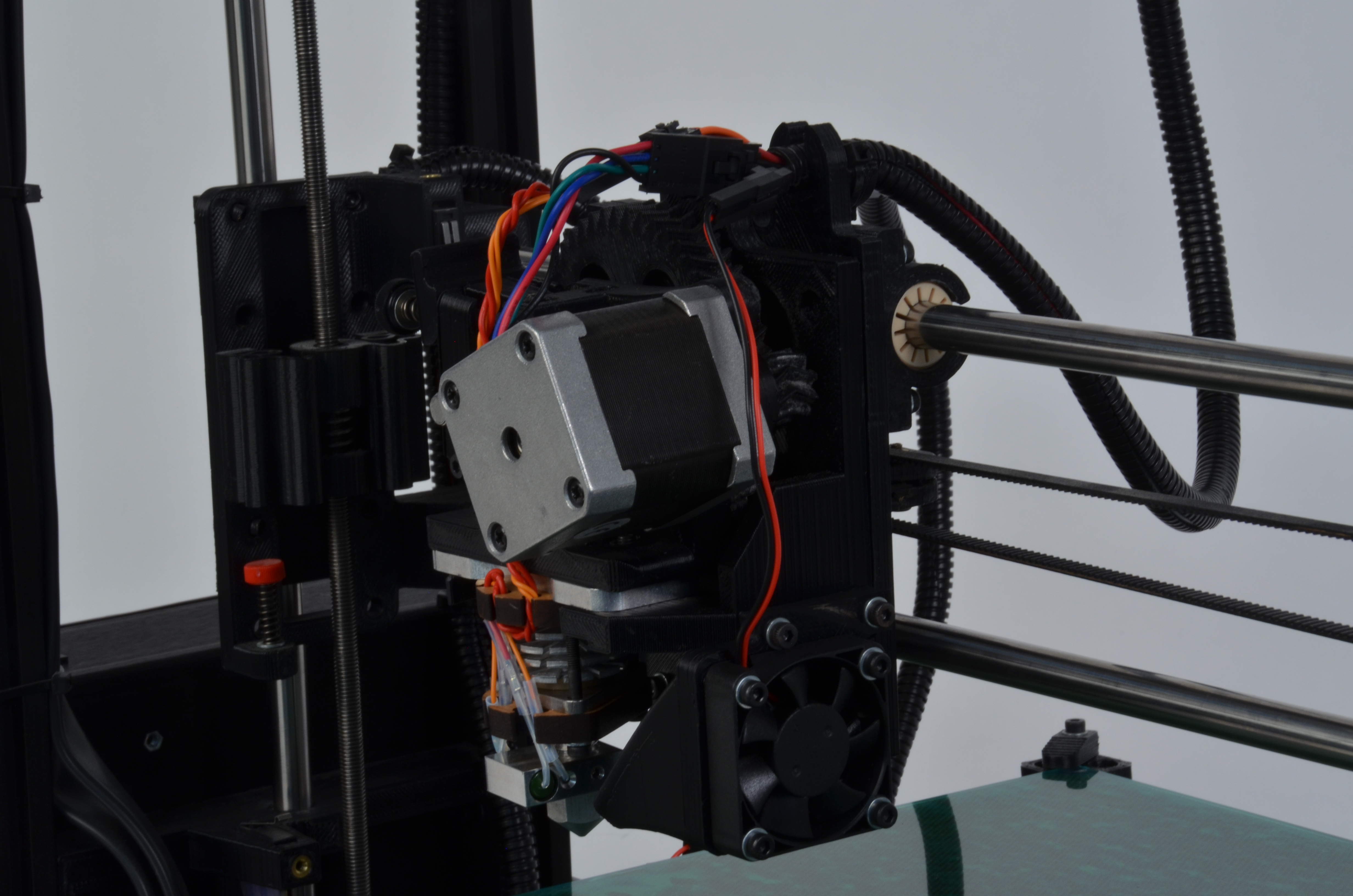
Cut the zip tie found on the X axis carriage securing the x axis wiring harness to the carriage. Take care to not damage the wires found within the harness or the wire harness wrap.
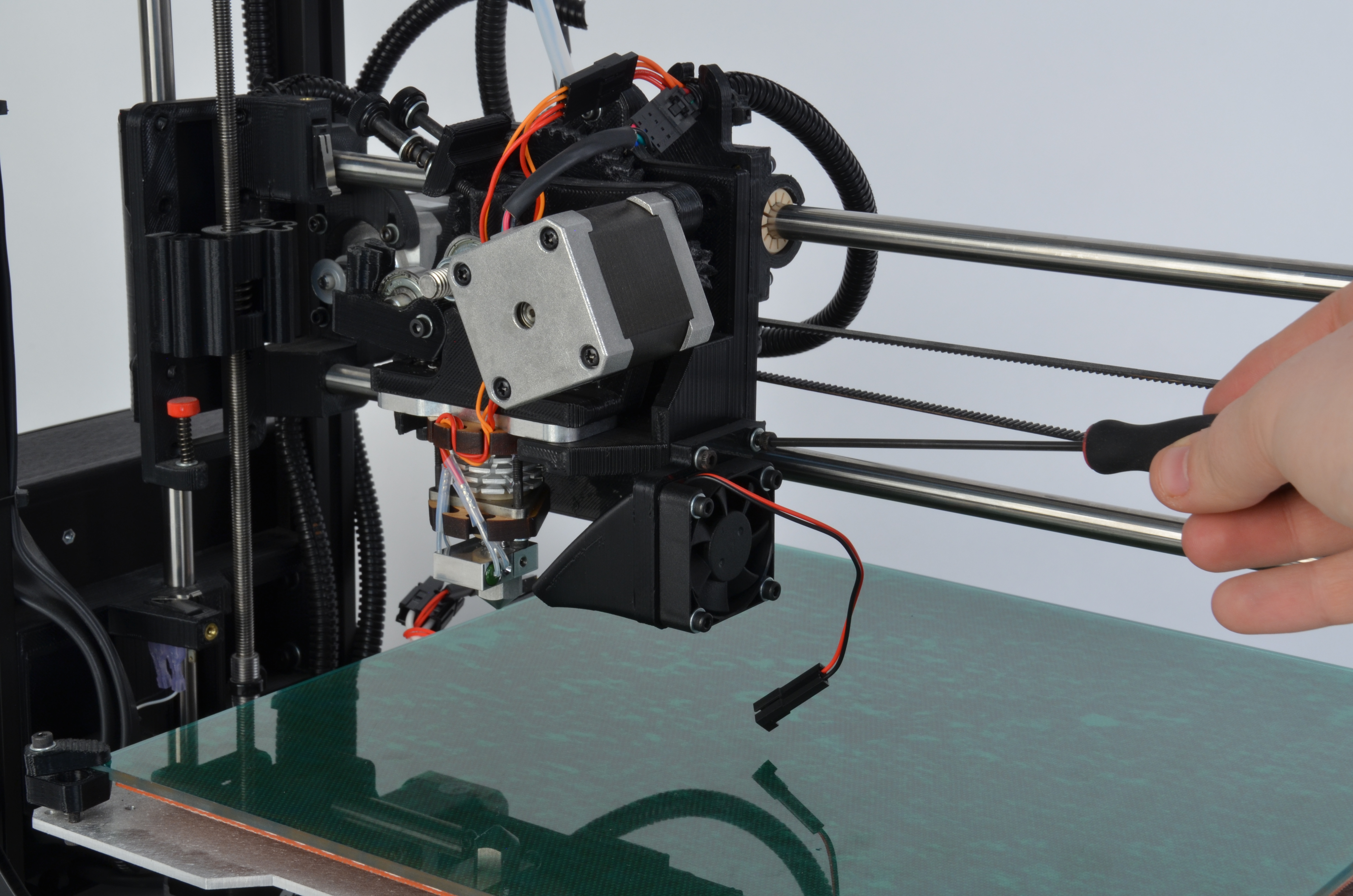
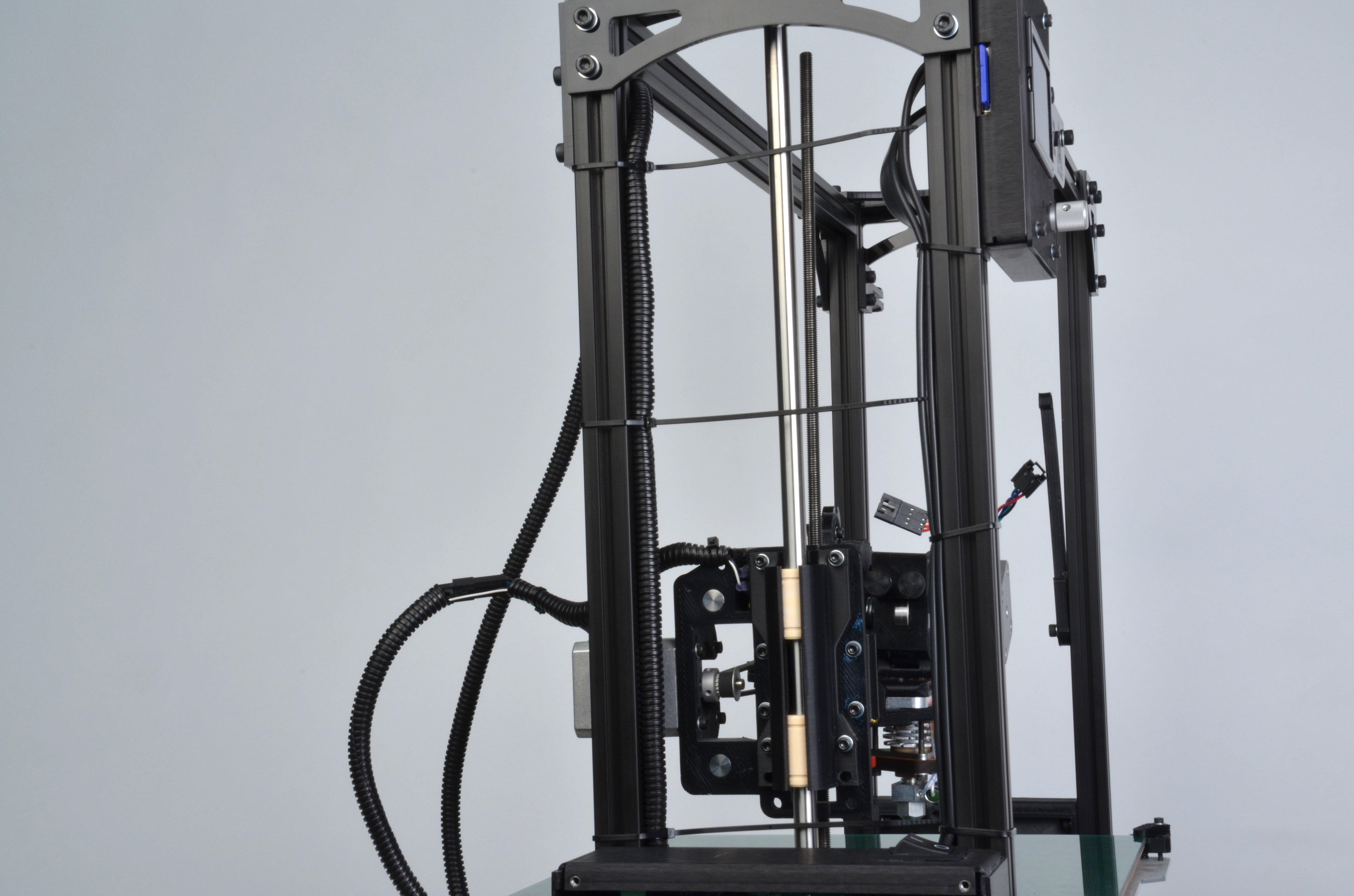
Cut the zip ties holding the X axis wiring harness to the TAZ frame.
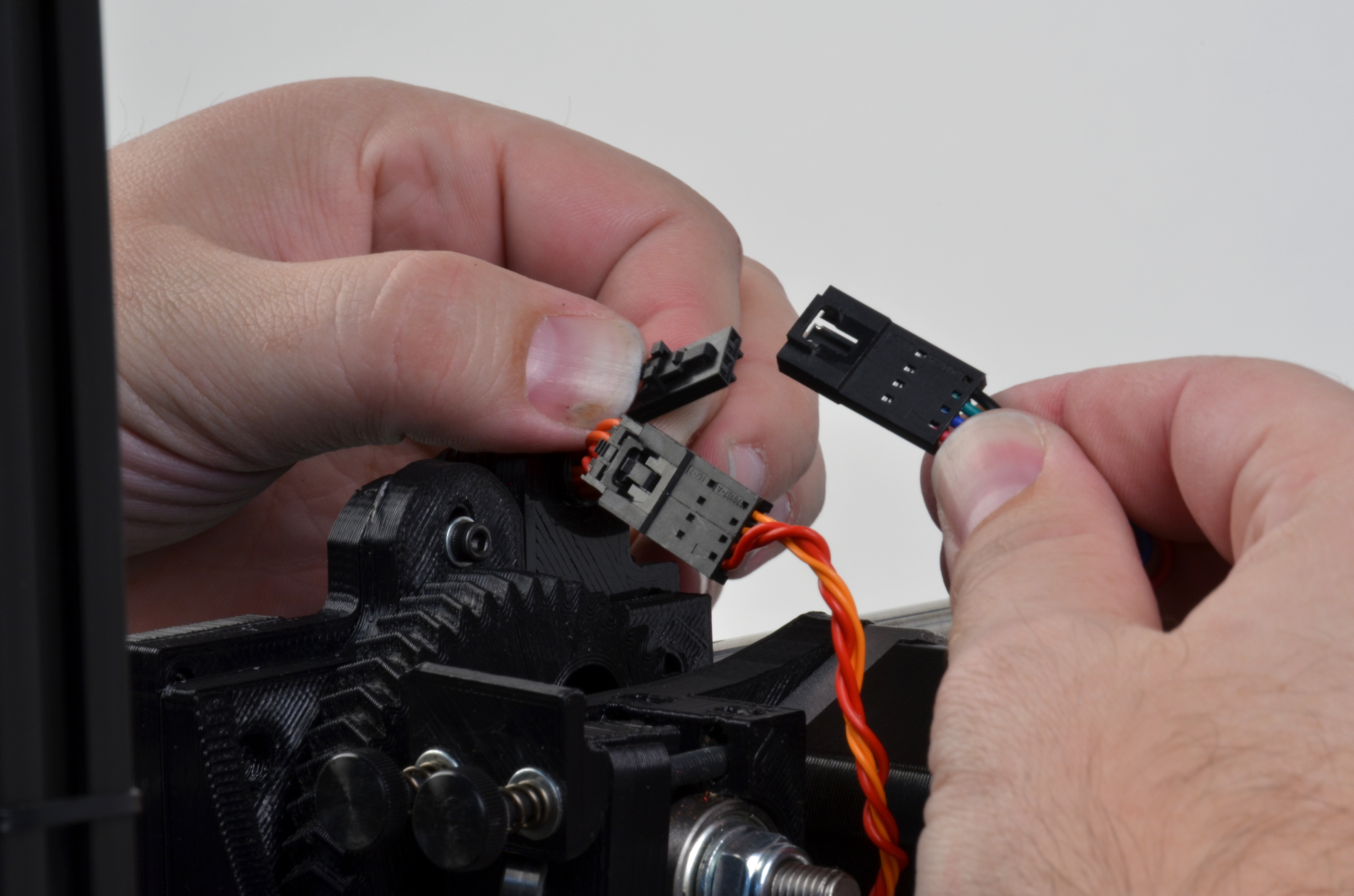
Disconnect the hot end and the stepper motor connectors.
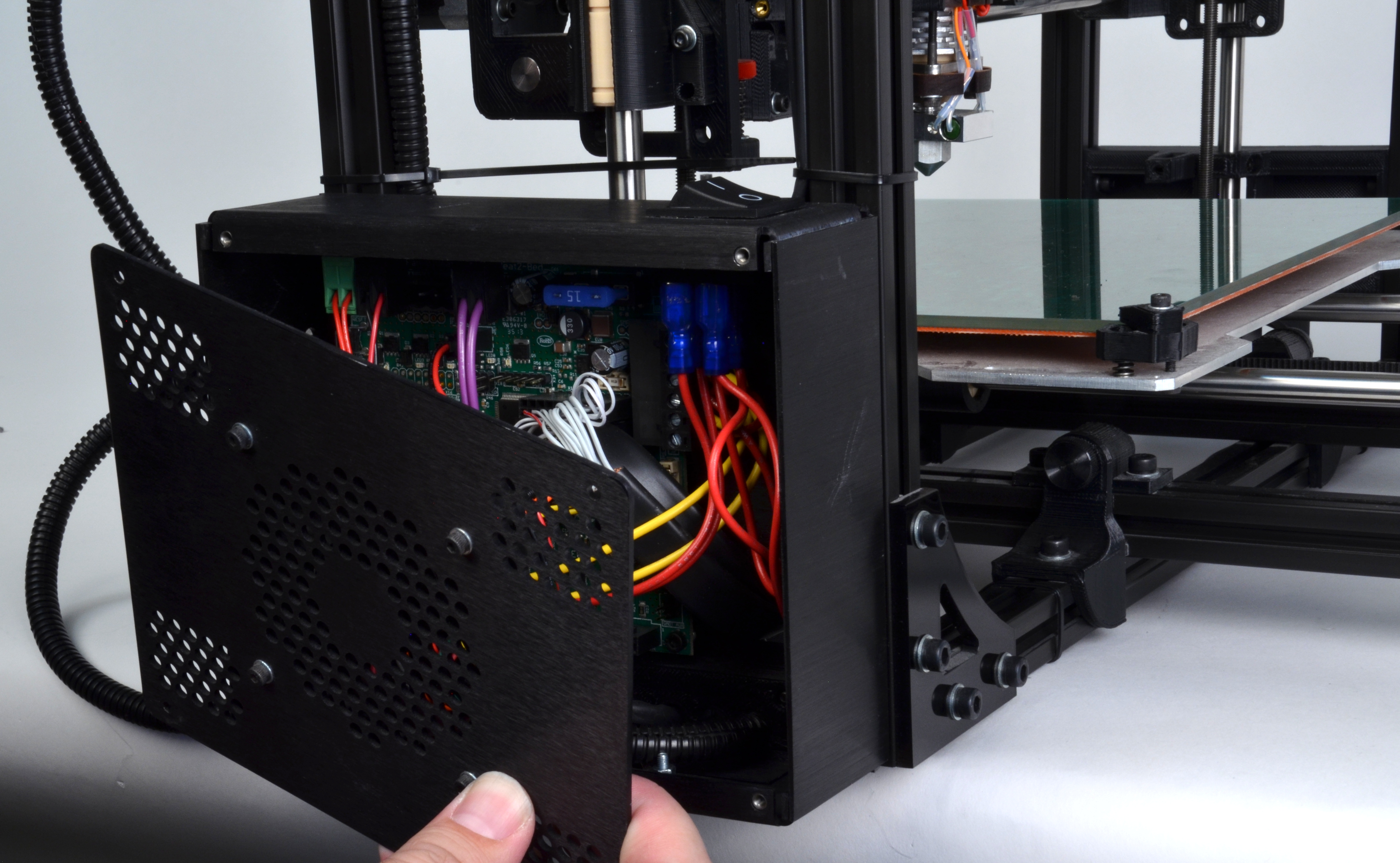
Use the 2.5-mm driver to open the electronics enclosure.
Remove the 4 corner screws.
Since the fan is still connected to the RAMBo board, carefully remove the lid and move to the side.
Unplug the fan wiring connector and set aside the lid.

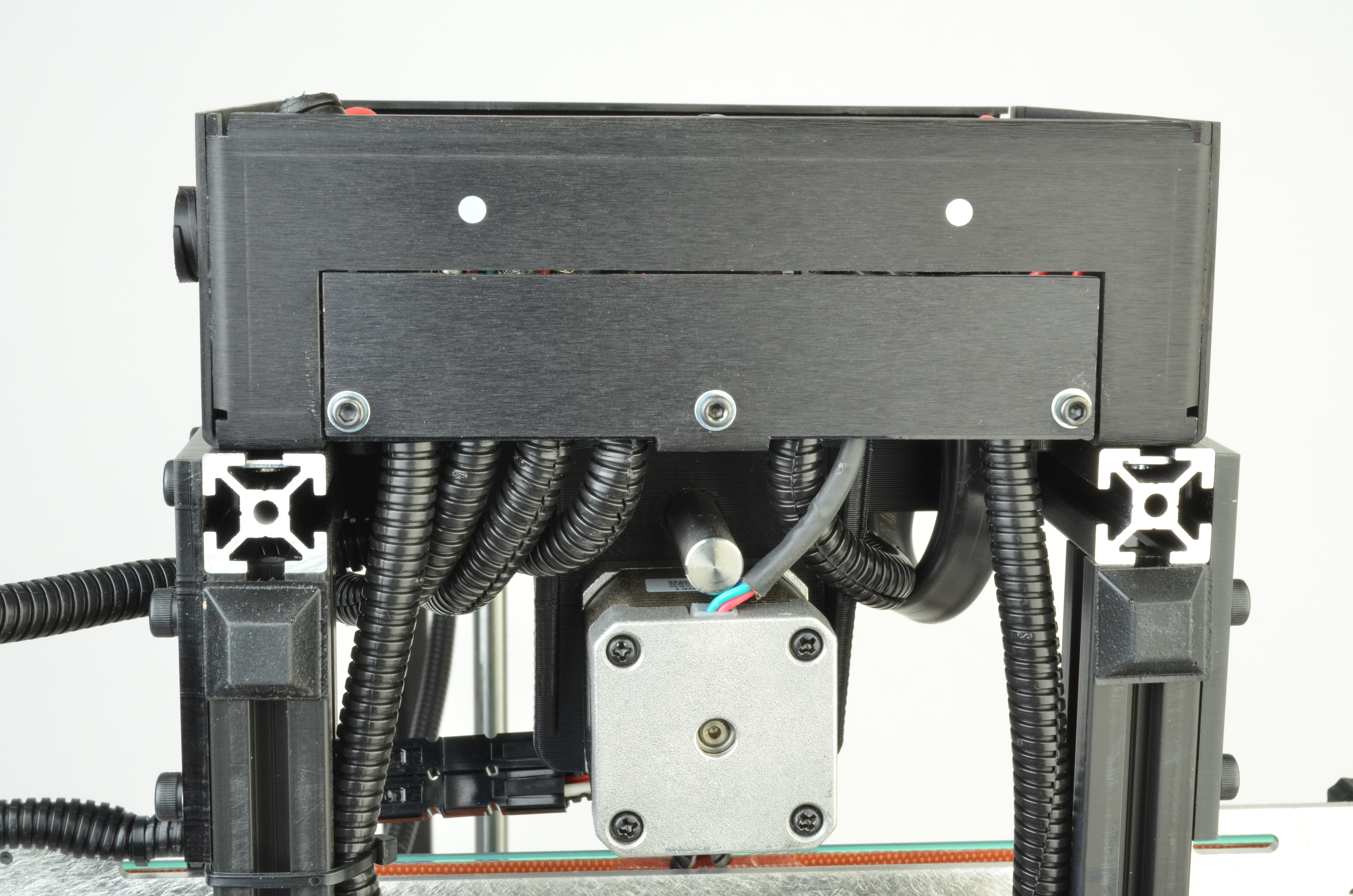
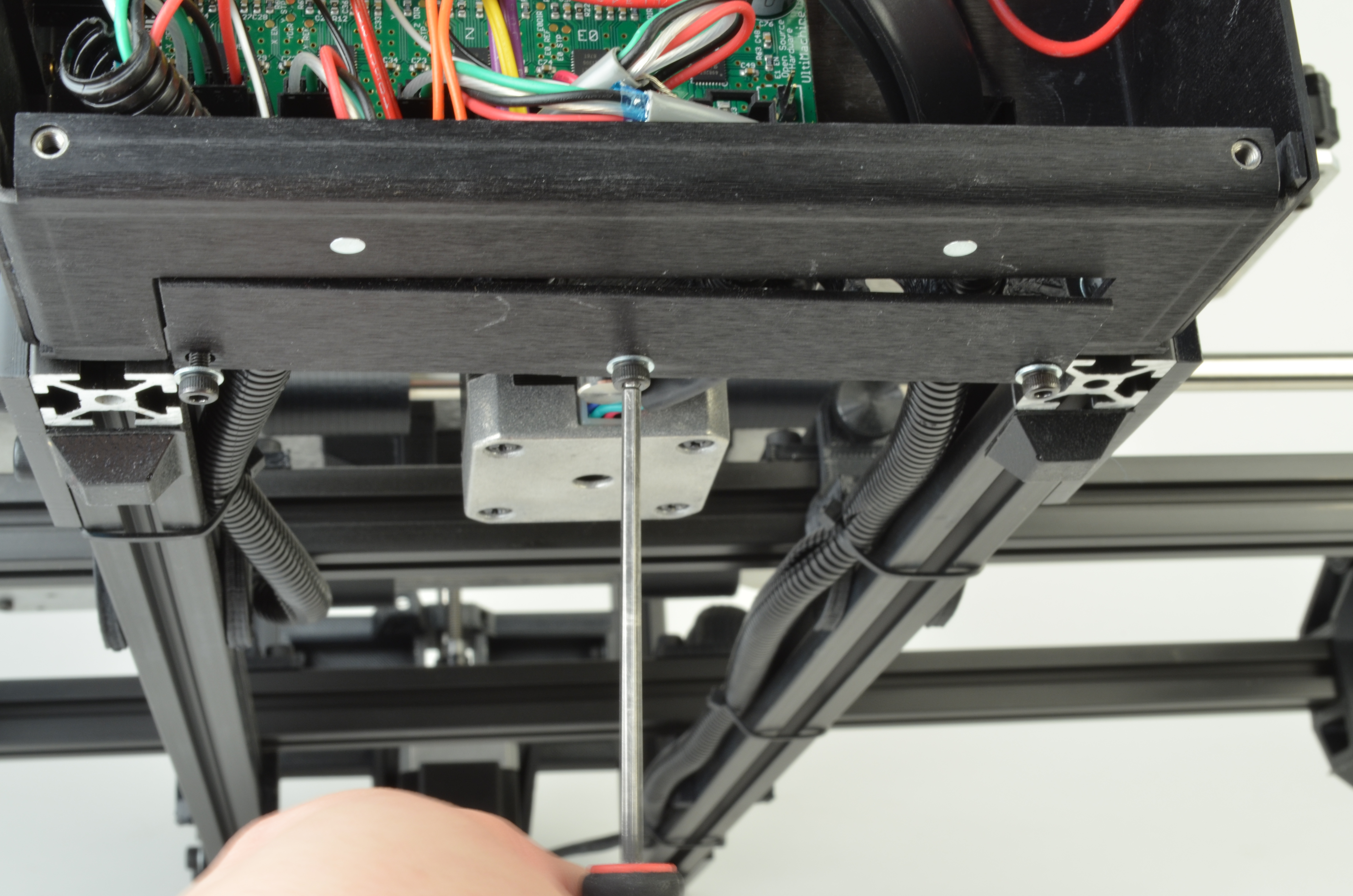
Remove the wiring access pane by removing the ___3 M3 screws__ from the base of the electronics enclosure.
The plastic stress relief strip will now be removed. This will allow access to the wiring.
Completely remove the hot end wiring harness from both the X axis carriage and the RAMBo board.
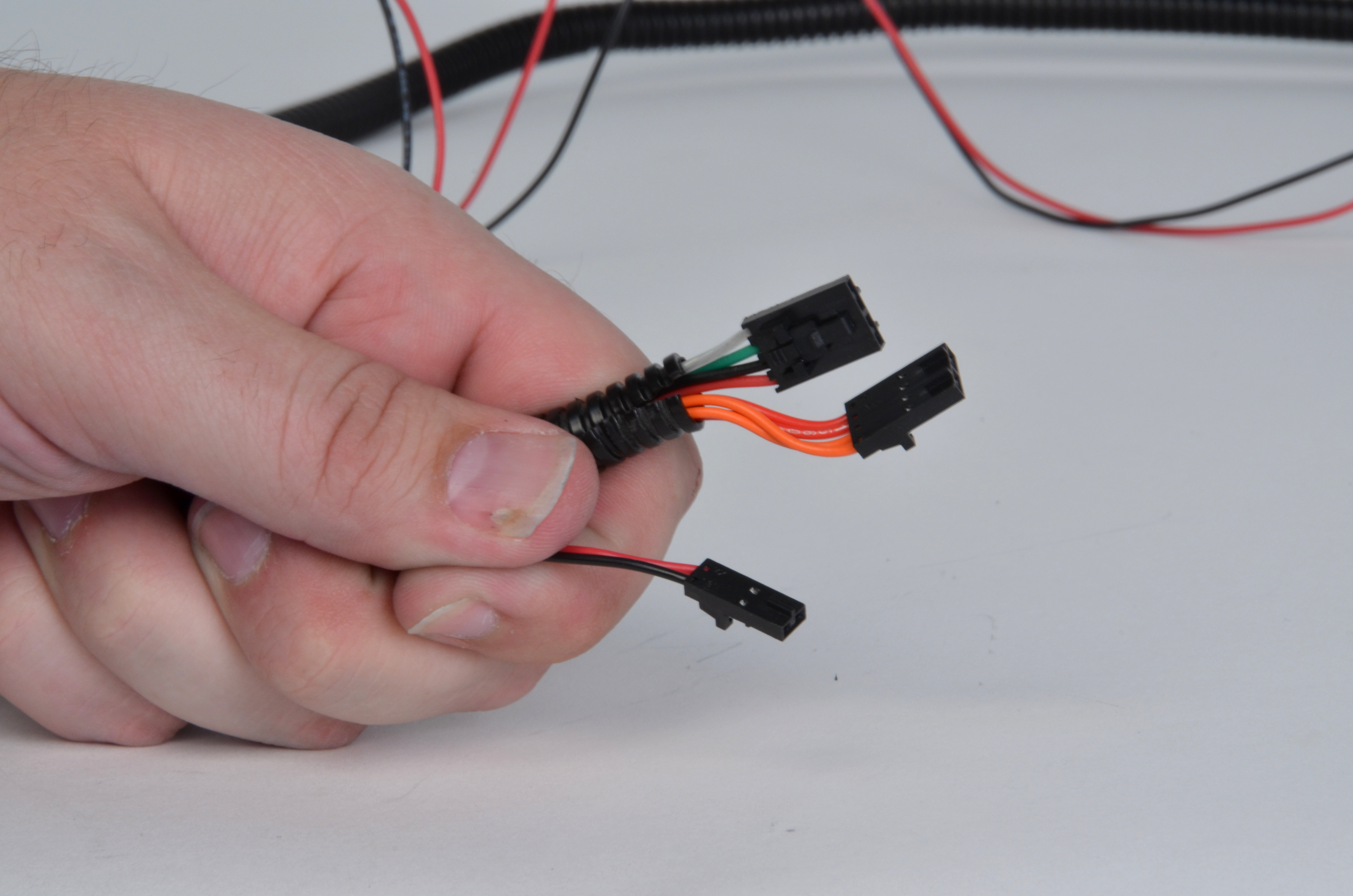
Hold the small locking connector next to the existing X axis wiring connectors.
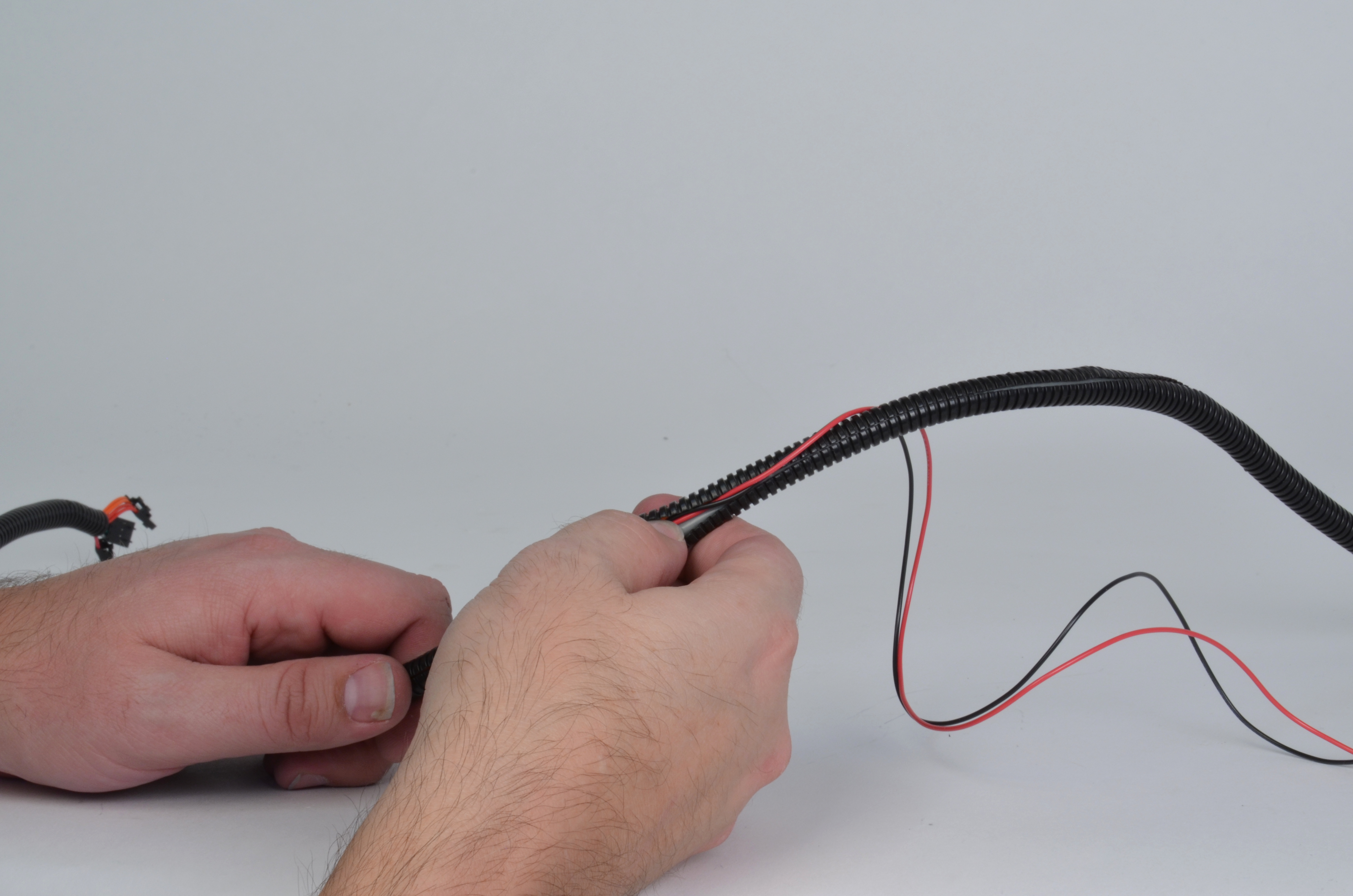
Open the wiring harness with your finger and remove the current wiring harness.
Place the fan wiring with the hot end wiring bundle.
Guide all the wiring back into the wiring harness.
Continue working down, guiding the fan wiring into place.
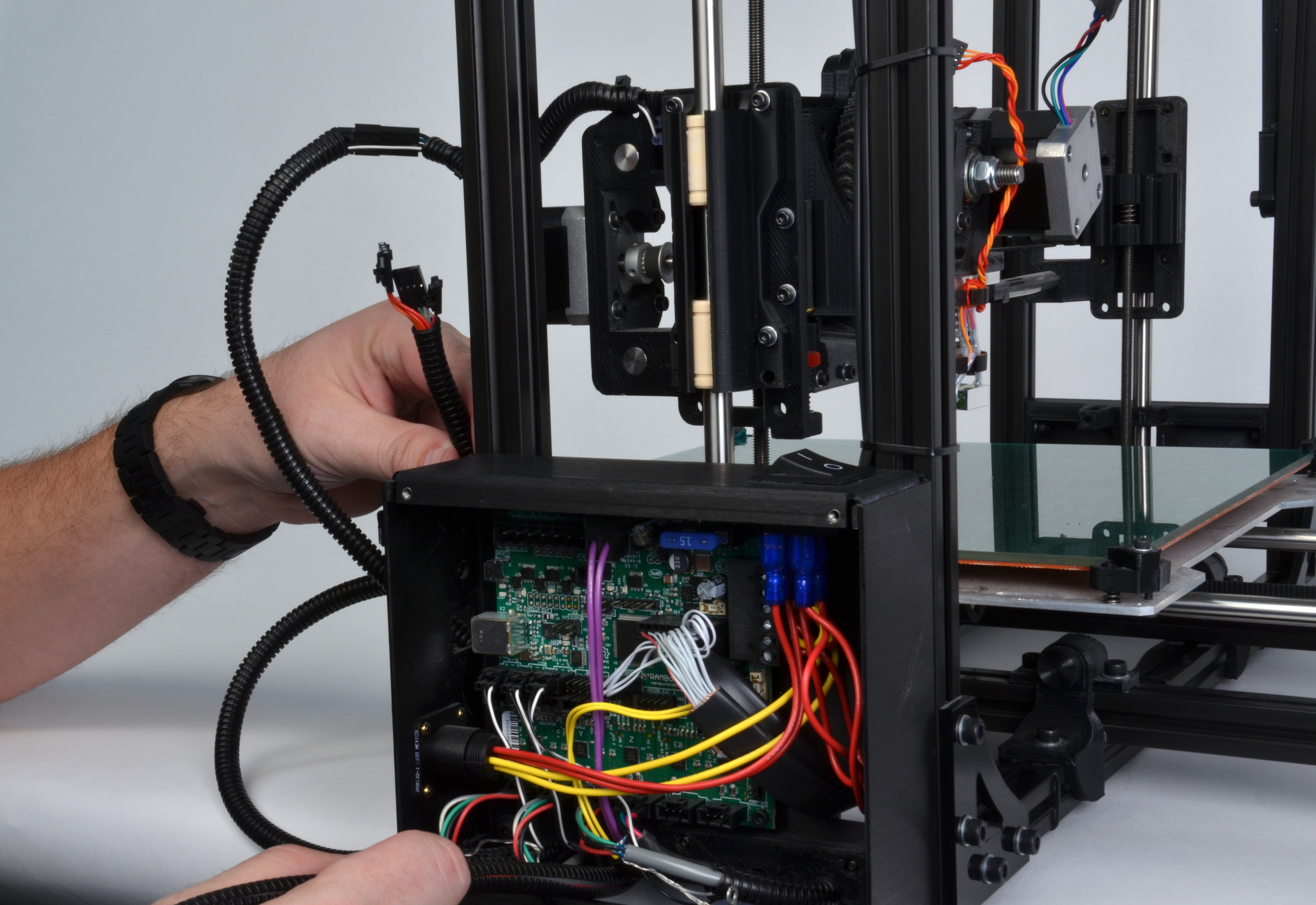
Bring the X axis wiring harness back into position near the X axis carriage and attach the wiring harness to the X axis carriage using a zip tie.
Use zipties to secure the wiring harness to the TAZ 3D printer frame, making sure to leave enough room to route the wiring harness to the board.
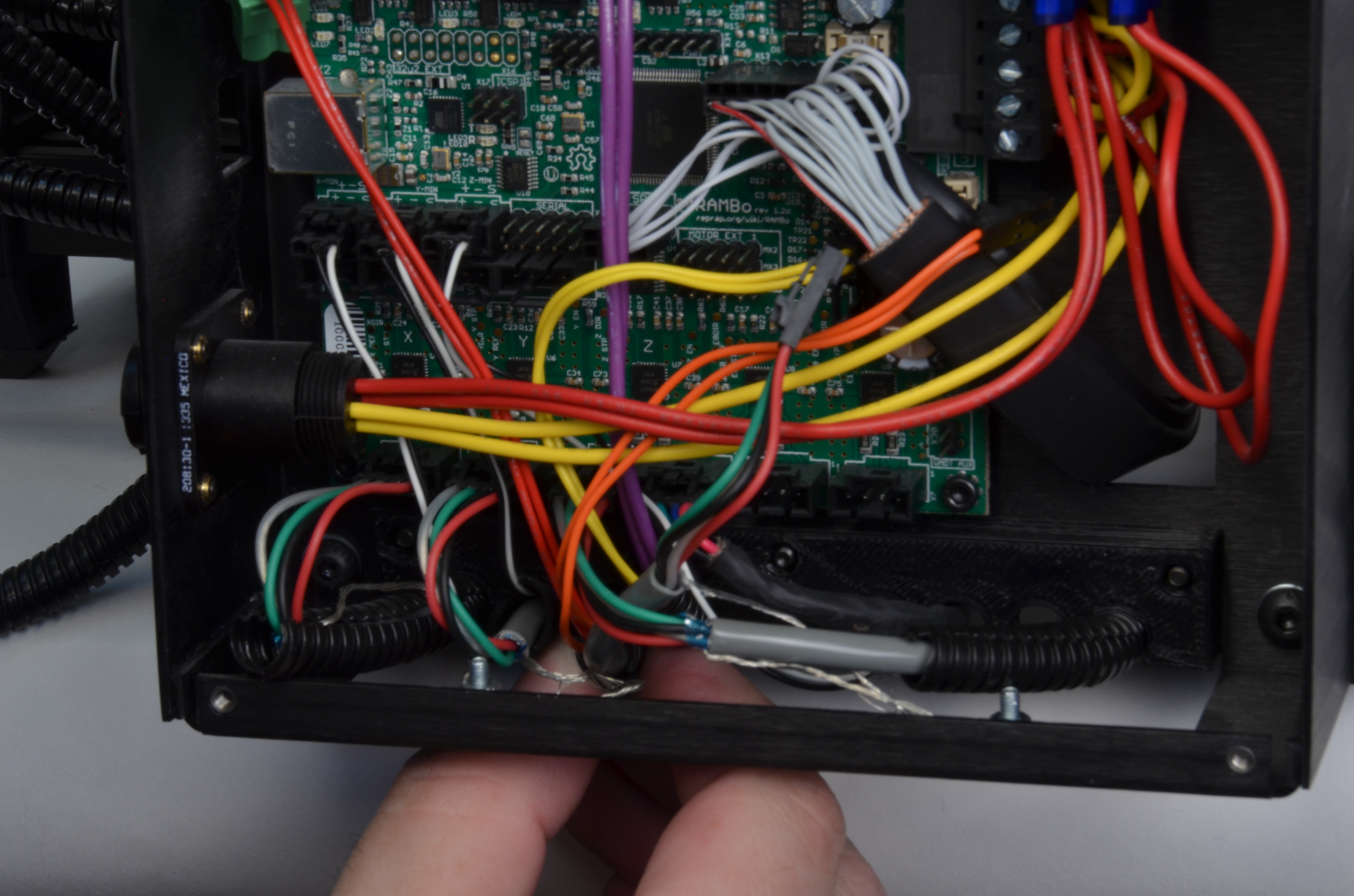
Connect the wiring harness to the board
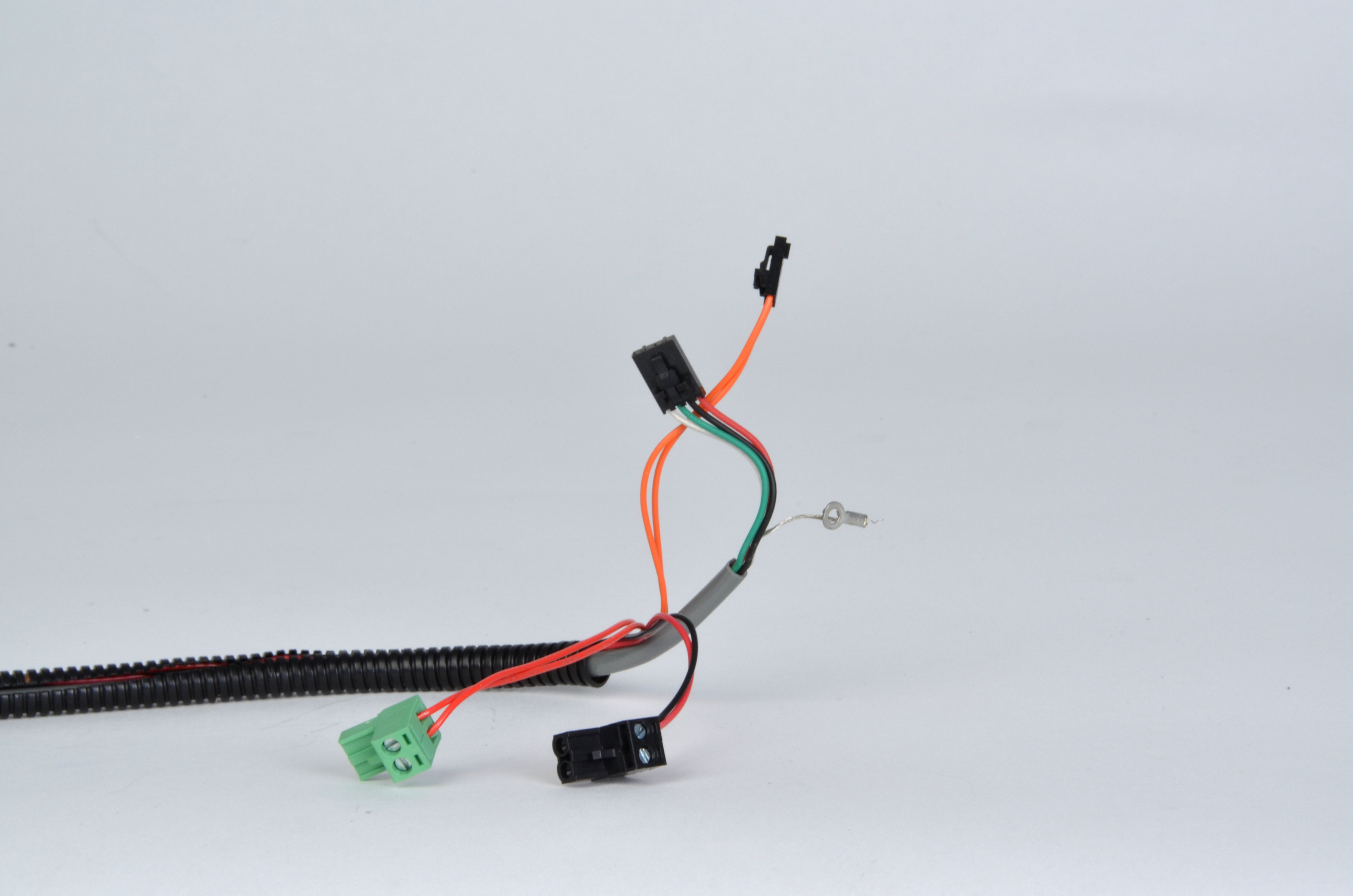
Connect the Green Heater Screw Terminal into the first left hand connection along the top of the RAMBo labeled Heat 0.
Connect the Black Thermistor Connector to the thermistor connection found on the left hand side of the RAMBo labeled T0.
Connect the Black Fan Screw Terminal into the connection labeled Fan 0 found along the top of the board, next to the Heat 0 connection.
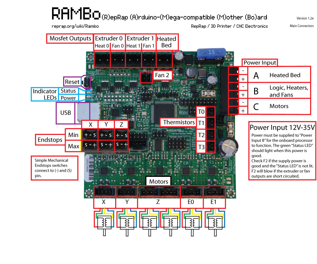
Connect the Enclosure Fan Wiring back into the connection labeled Fan 2, with the Black Wire towards the left hand side, on the same side of the board as the silver USB connection port.
Make sure that the wiring will not interfere with the fan operation.
Reattach the electronics enclosure using the__2.5-mm driver__ and the 4 M3 Screws on each corner of the lid.
Make sure that the left hand side of the X axis carriage is accessible.
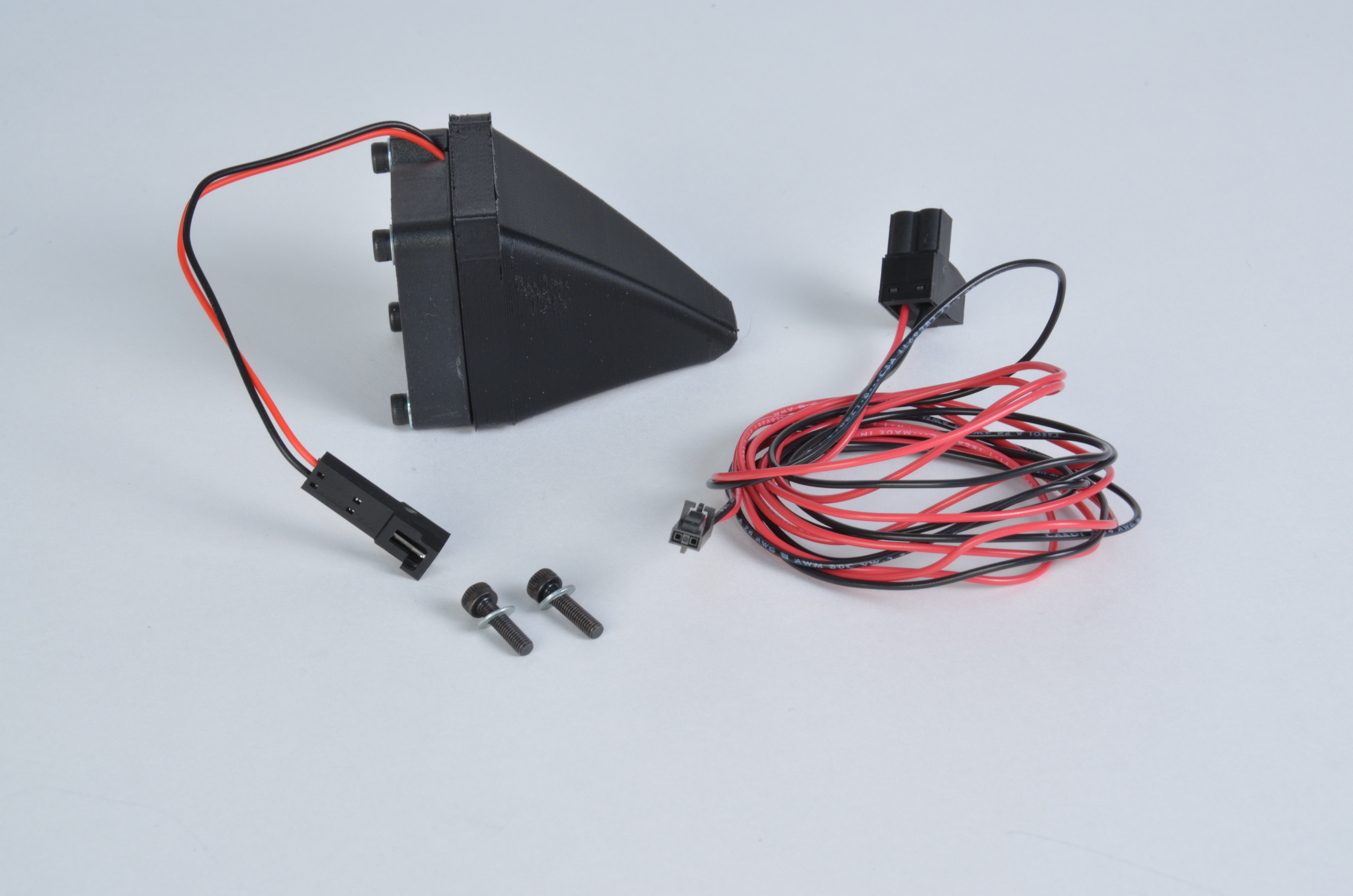
Use the 2 M3 screws with washers to mount the fan assembly to the X axis extruder toolhead. Do not overtighten.
Plug in the fan wiring into the wiring harness.