Project Dashboard TAZ 3 TAZ Calibration Workflow

1 Gather Tools and Components

  • Components for calibration
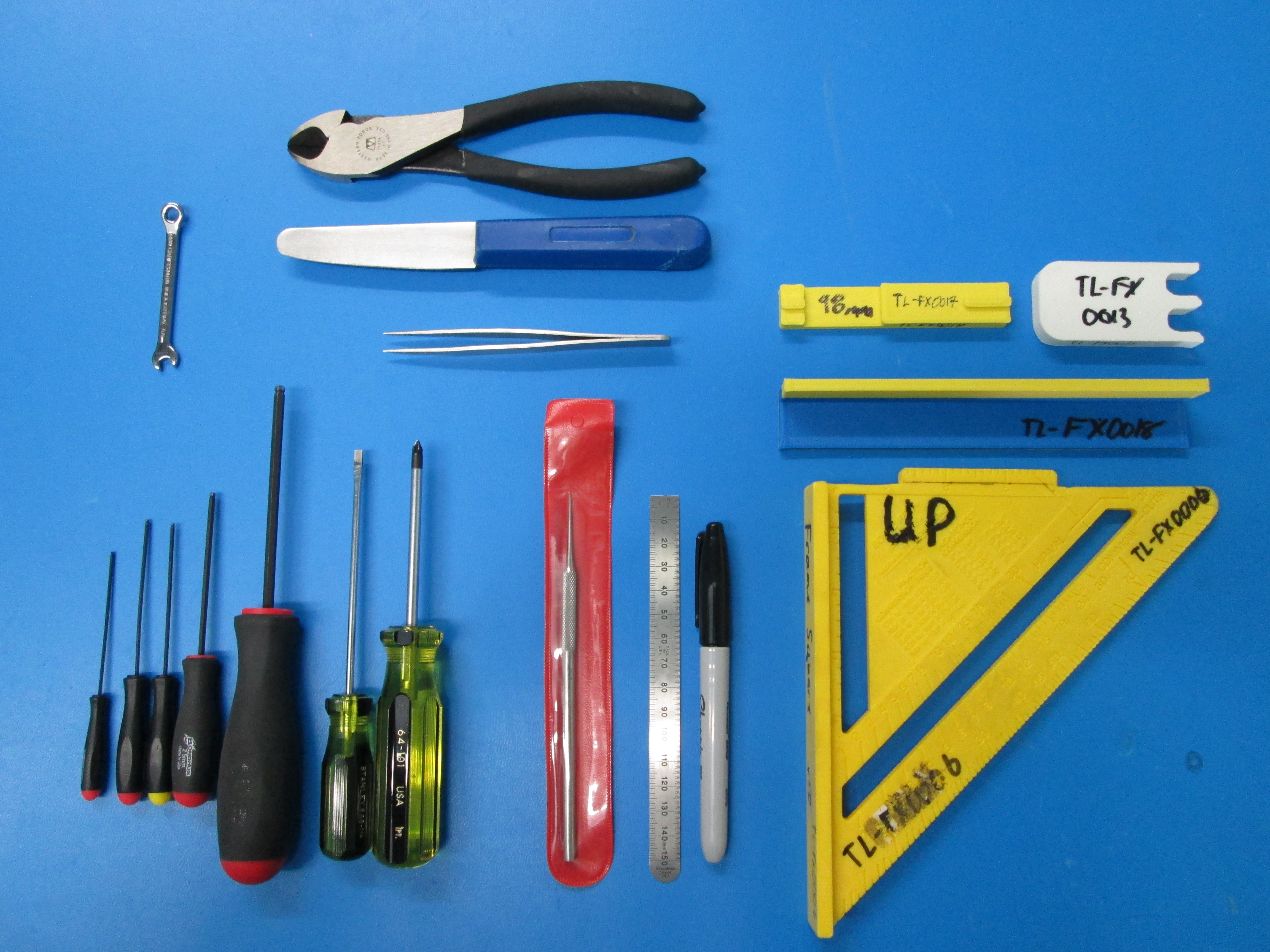
    • Power supply
    • Power cable
    • USB cable
    • Serial number
    • Temperature warning clip
    • SD card with calibration files
    • Feed tube sub-assembly
  • Tools

    • TL-FX0006 square fixture
    • TL-FX0018 173mm fixture
    • TL-FX0017 98mm fixture
    • TL-FX0013 10mm spacer
    • Tweezers
    • Dental pick
    • 150mm ruler
    • Sharpie fine point marker
    • Diagonal cutter
    • Clam knife
    • 4mm Allen driver
    • 2.5mm Allen driver
    • 1.5mm Allen driver
    • 1.27mm Allen driver
    • 1/16" Allen driver
    • Phillips head screwdriver
    • Flat head screwdriver
    • 5.5mm combination wrench
Calibration components
Required tools

2 Quality Check

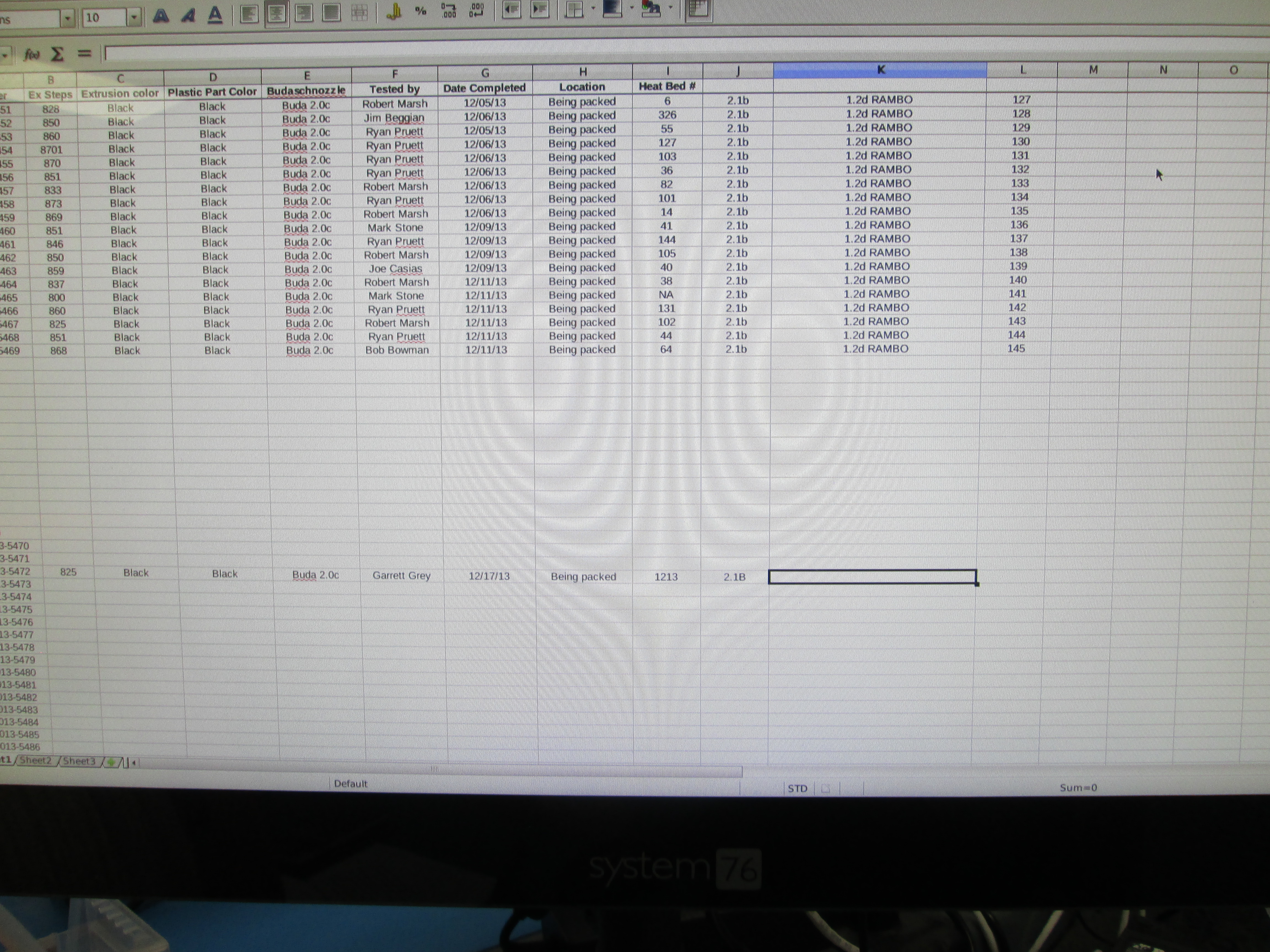
  • Gather the required documents.

    • You will need a Quality Checklist and a Test/Acceptance Record.
    • Take the next available serial number for the machine. There should also be a matching number for the power supply.
  • Inspect the mechanical assembly - complete the Quality Checklist as you proceed.

    • Check to ensure that all screws and zip ties are tight and in the correct position.
    • Make sure the X and Y motor pulley set screws are tight and that one of them directly engages the flat on the motor shaft.
    • Ensure that the belts are tight and do not rub on the idler end or belt mounts throughout the range of motion.
    • Belts should be trimmed far enough to prevent interference.
    • Check that the X axis smooth rods are aligned flush with the X motor mount and the Z smooth rods are flush with the top of the unit.
    • The Y axis smooth rods should be flush with both Y ends.
    • Ensure the drive rod zip ties are very tight (vertical pull test).
    • Make sure the Y frame is directly contacting the XZ frame.
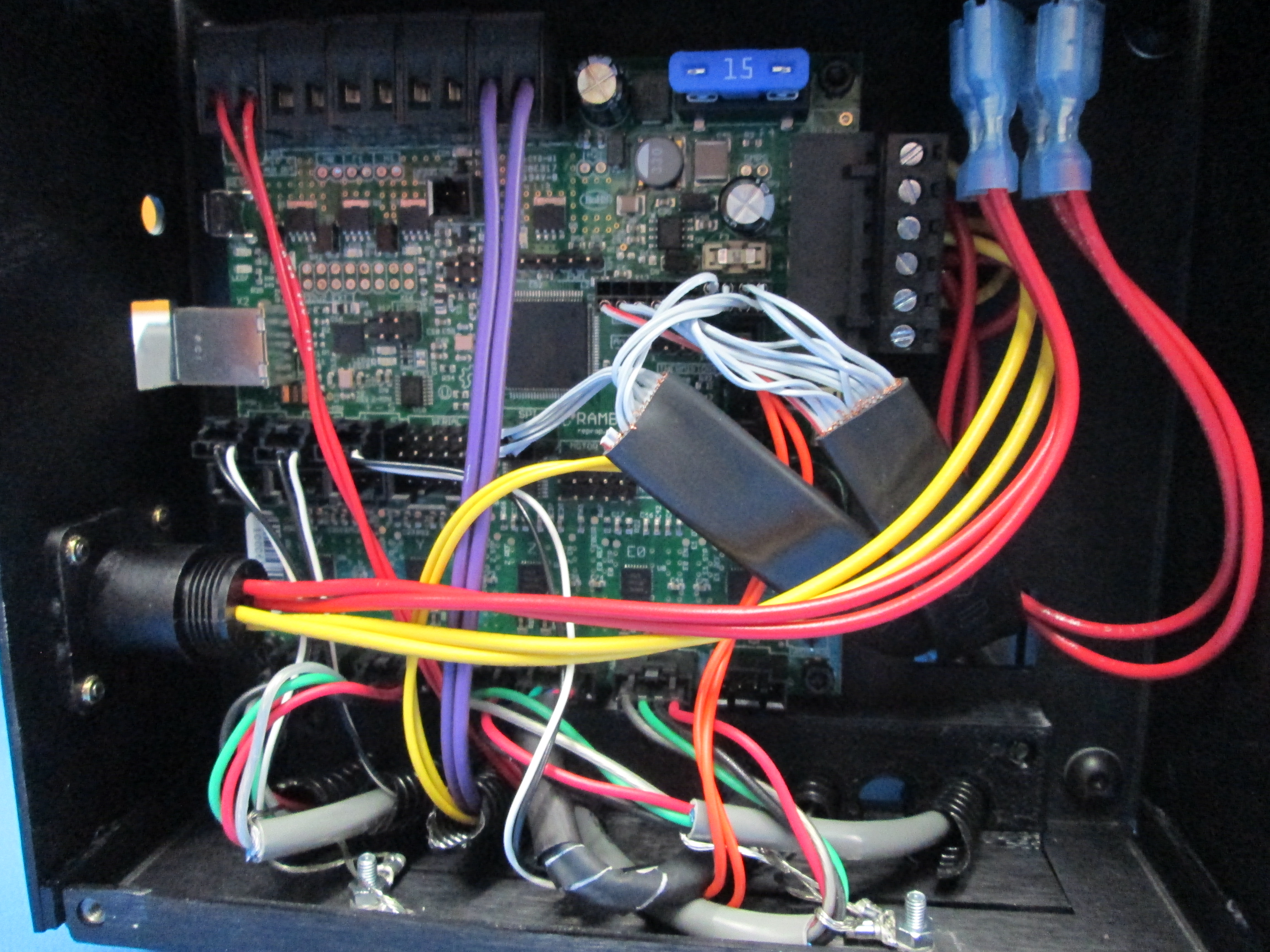
  • Inspect the electronics.

    • Check the wiring for correct positions.
    • Verify that no wire insulation is inside the screw terminals and check for screw tightness.
    • Make sure that all plug connectors are fully seated and in the proper locations.
    • Ensure the lower strain relief is installed and screws are tight.
    • Check that both nuts on the 3mm ground lugs are tight.
    • Install the cooling fan using 4x 3mm x 12mm screws and washers. Power the unit on and check for fan rotation and interference.
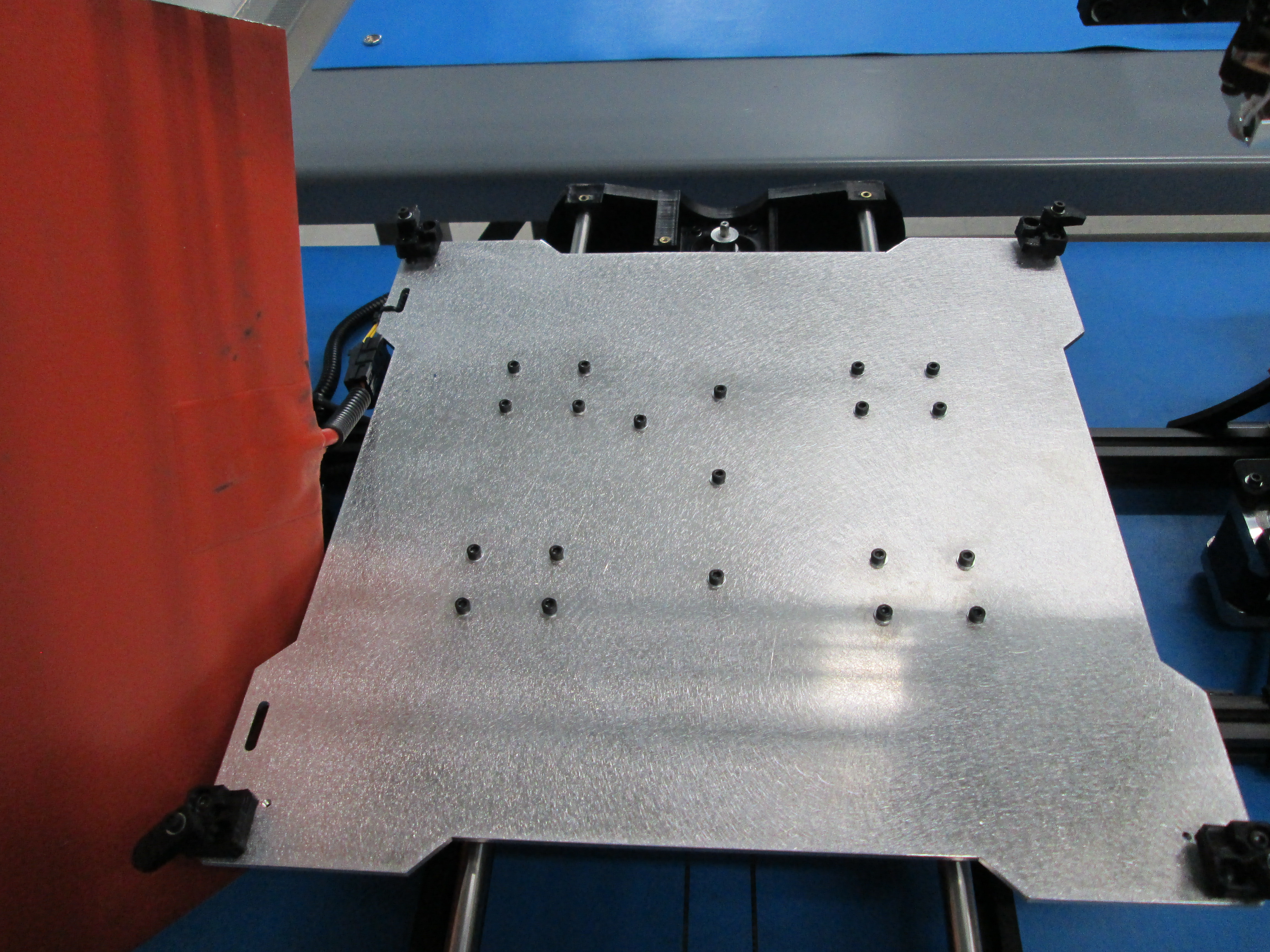
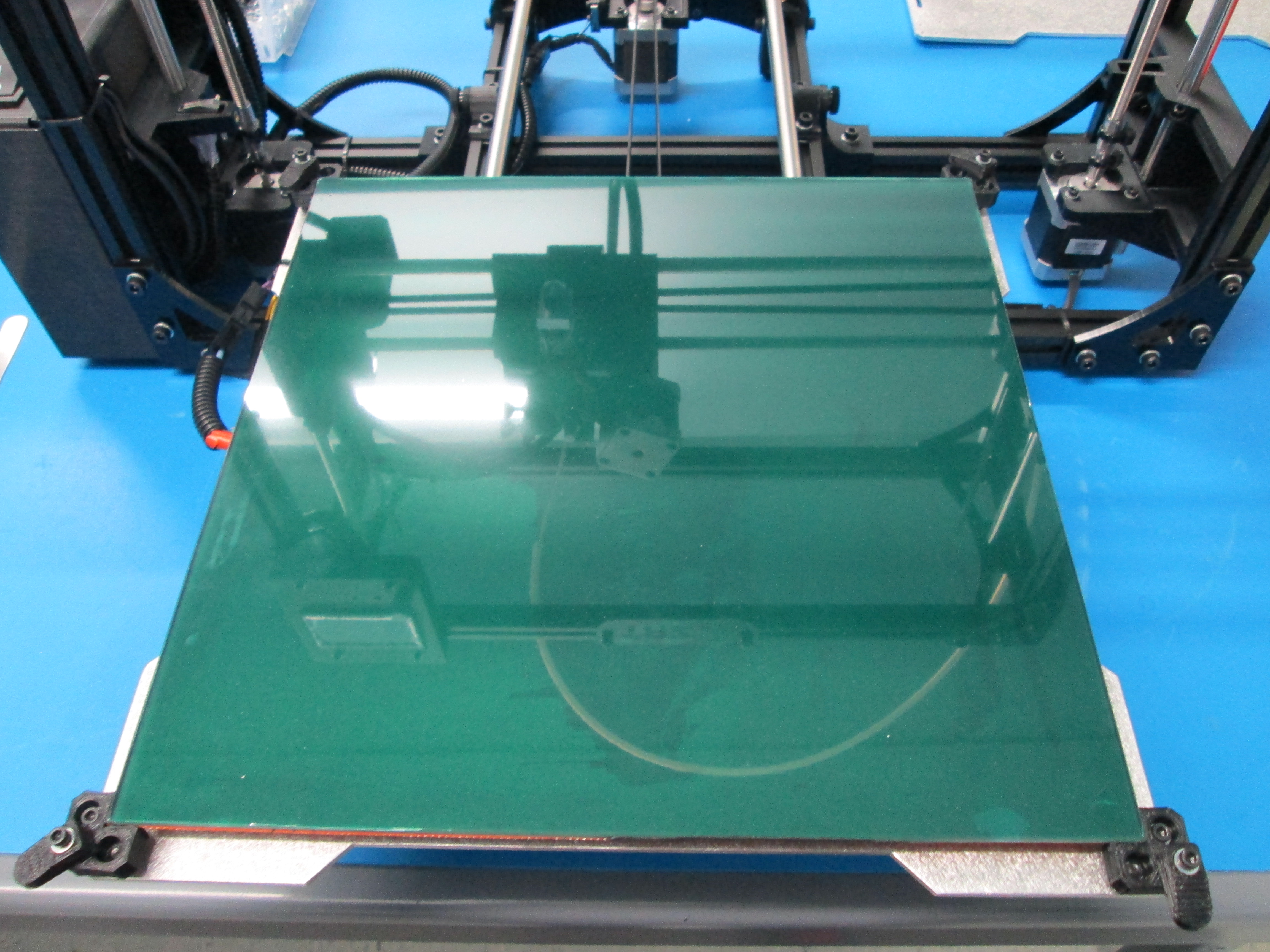
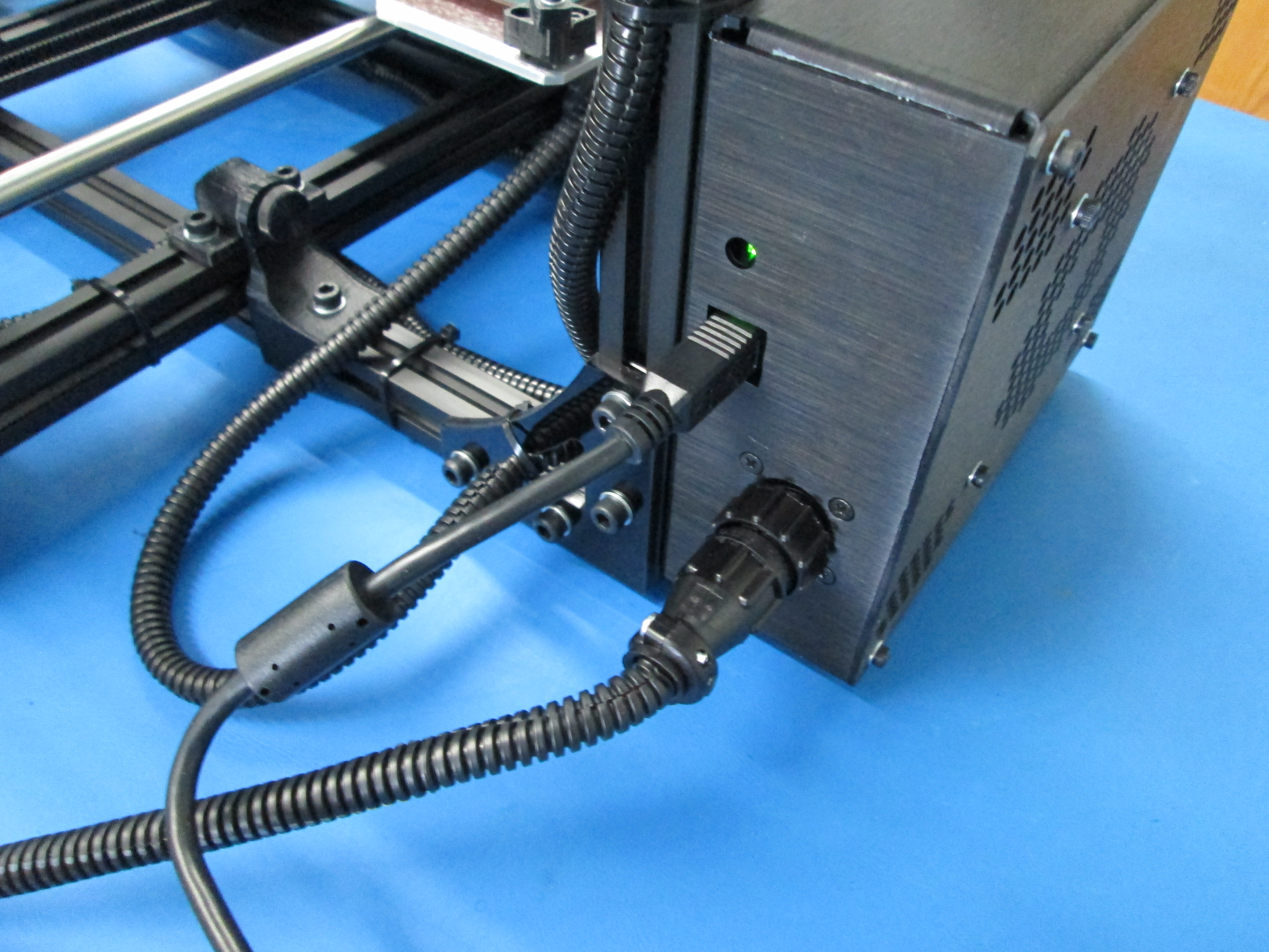
  • Install the heat bed as indicated. Connect the heat bed wires.

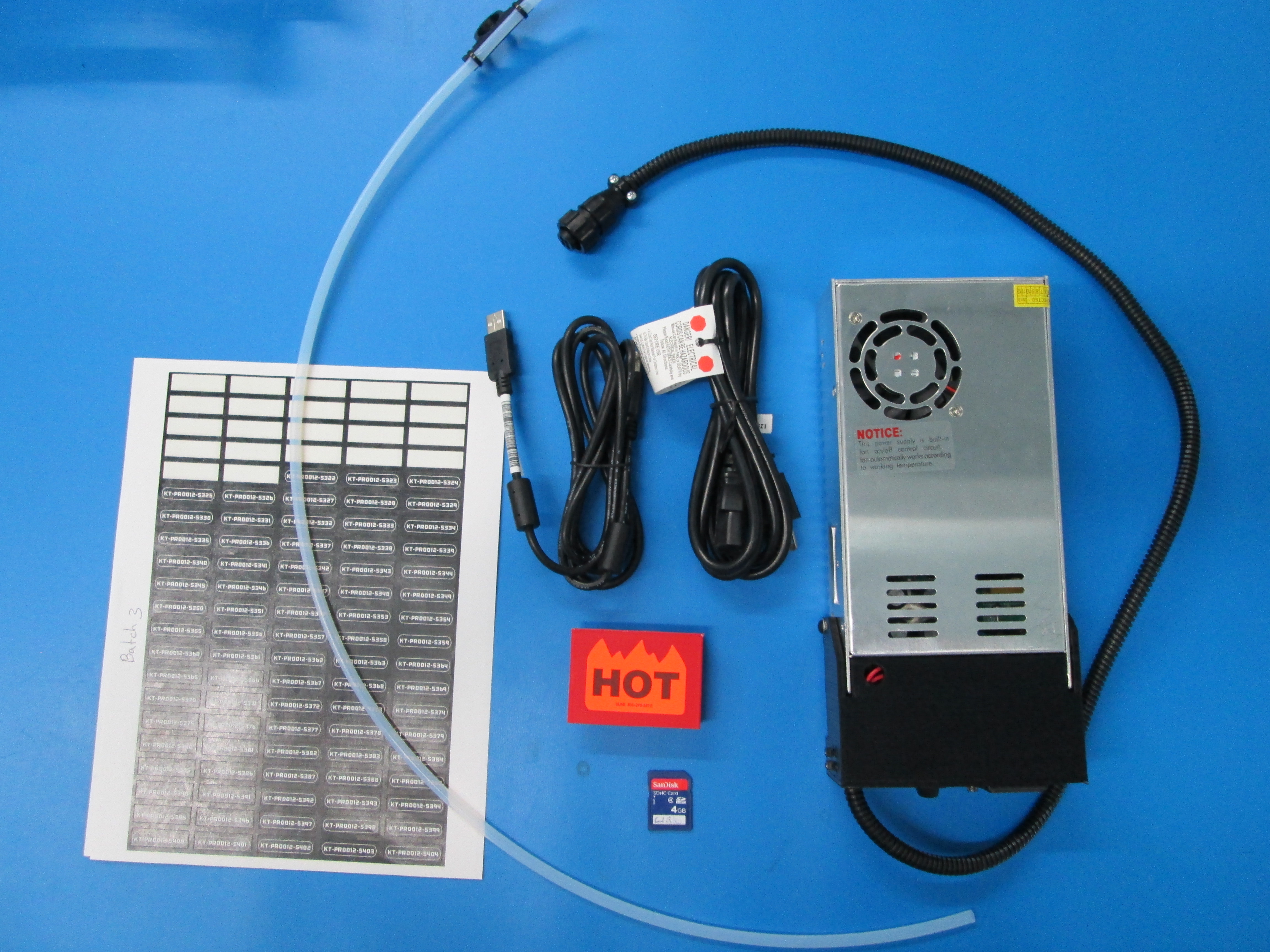
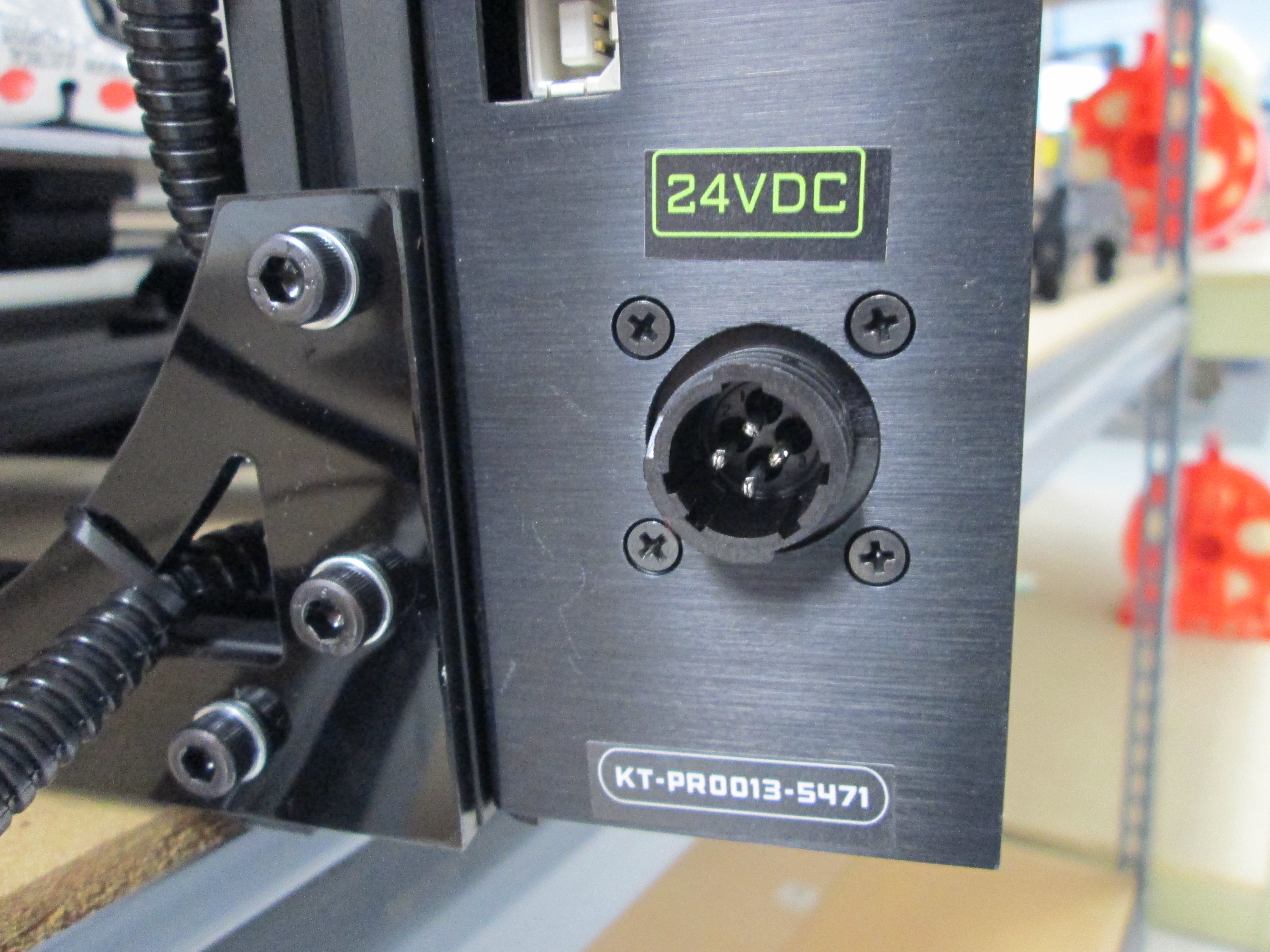
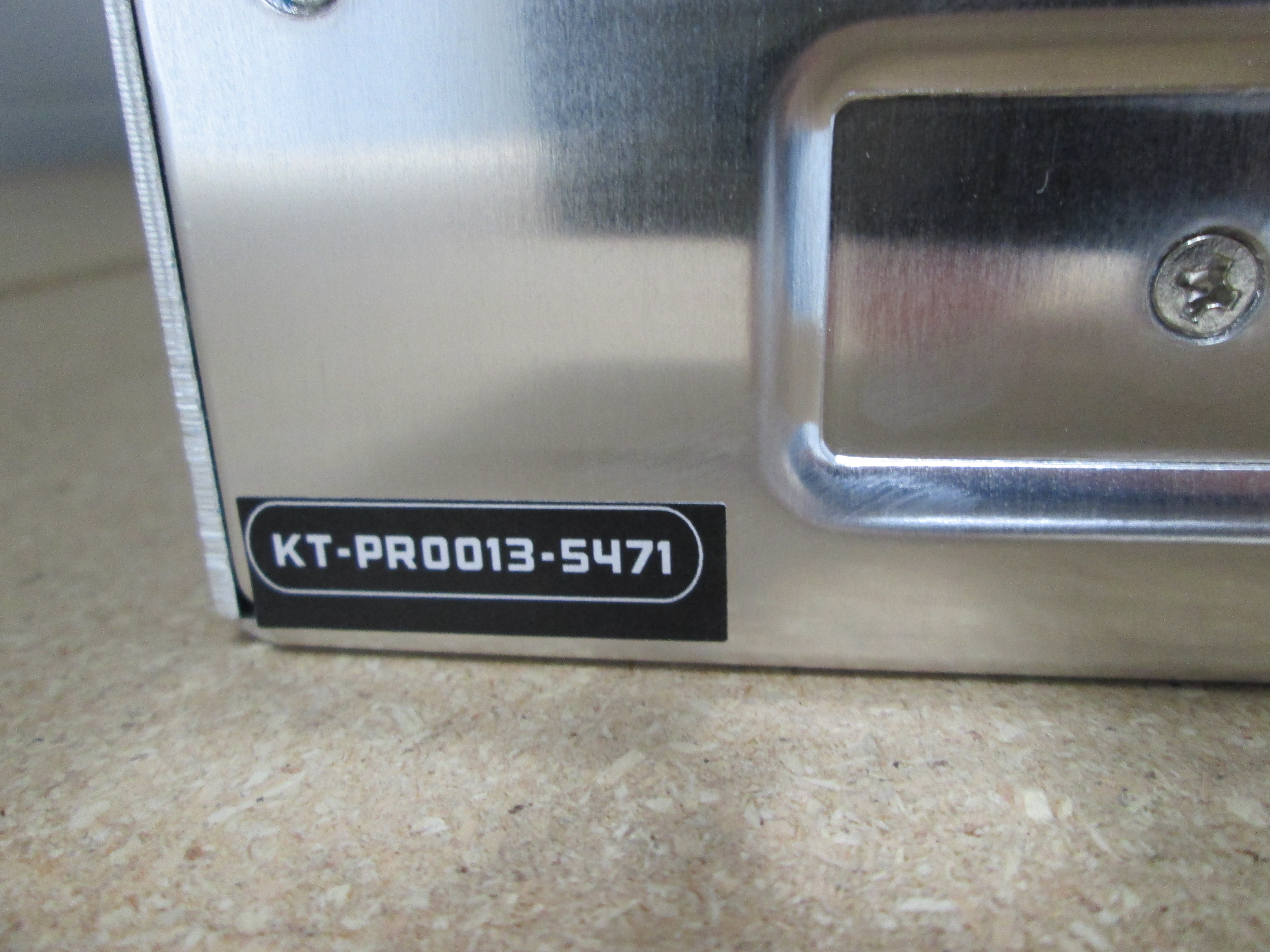
  • Install the serial number on the machine and power supply. Also apply the 24v sticker above the power connection as indicated.

Checking Y axis bearing screws
Checking Y pulley set screws
Both belts tight and trimmed
Smooth rods flush with X motor mount
Smooth rods flush with top - frame connectors clean and aligned
Smooth rods 4mm inside Y ends - check set screws
Check drive rod zips for tension (vertical pull test)
4x Y frame directly in contact with XZ frame
Inspect the electronics
Plug in the fan connector
Install the fan cover with 4x 3mm x 12mm screws and washers
Installing the heat bed
Machine serial and 24v sticker
Matching power supply serial

3 Flash and Test Firmware

  • Upload Firmware

    • Connect printer to PC with the USB cable.
    • Turn on power to power supply and printer.
    • Open Arduino software and load the appropriate sketch for the TAZ version.
    • From the tools menu, make sure you have selected RAMBo as the board and the appropriate serial port.
    • Click 'Upload' to compile the sketch and upload it to the printer.
    • The printer LCD should show the TAZ boot screen followed by the main menu.
  • Connect with Pronterface

    • Verify the connection port and click 'Connect' to connect to printer.
    • Keep your finger close to the power button. In case of malfunction, switch the printer off.
    • Click X home button to verify the stop position
    • Click Y home button to verify the stop position
    • Click Z home button. Manually depress the Z limit switch before the nozzle contacts the heat bed. Do not allow the nozzle to apply pressure to the bed, the glass may crack!
Connect printer to PC with USB
Open Arduino software, load sketch and upload to RAMBo
LCD boot screen after successful upload
Info screen
Connect to printer with Pronterface
Set home for Z axis

4 Make X parallel to bed

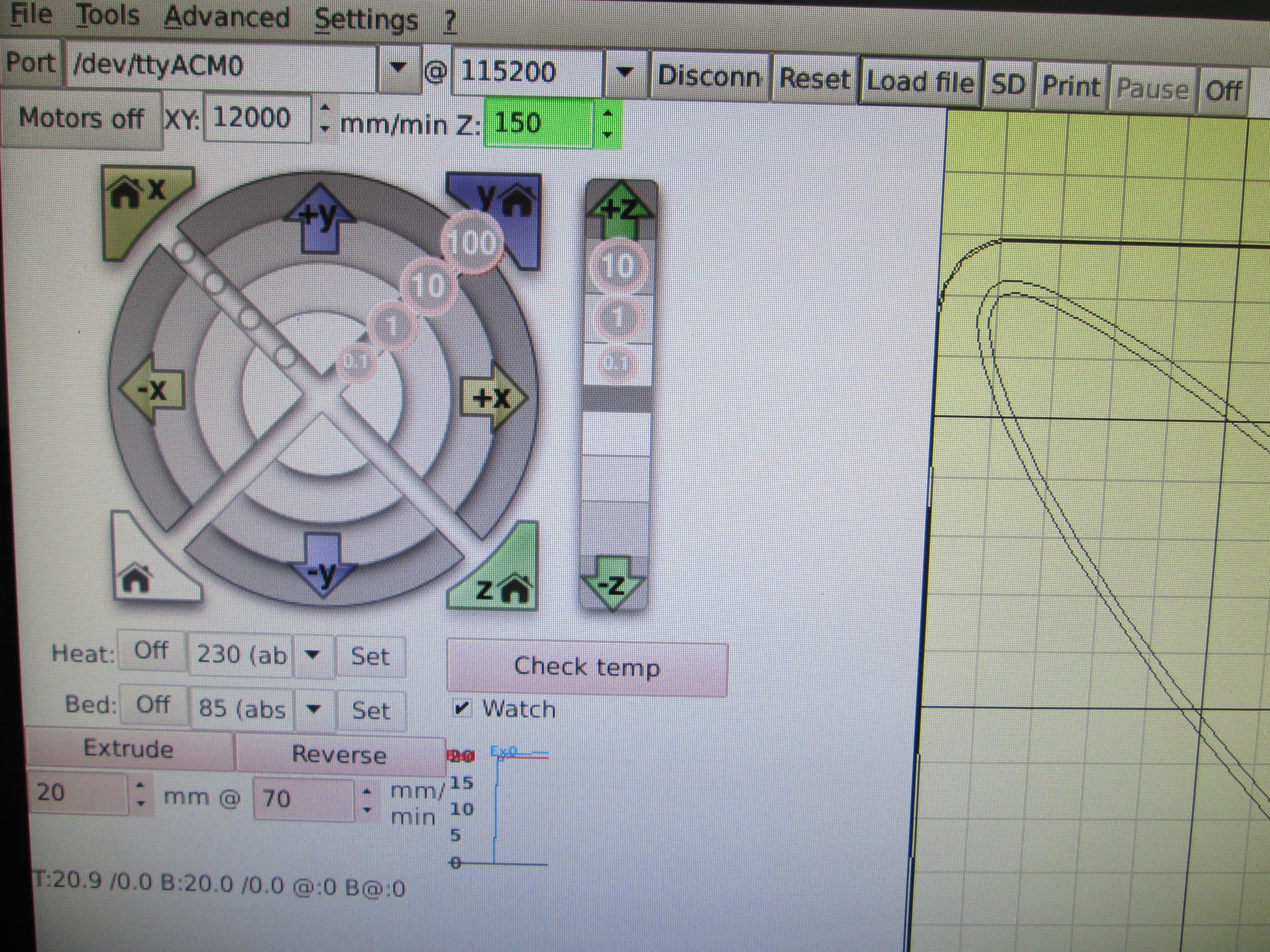
  • Make sure Pronterface is connected to the printer then click the 'MOTORS OFF' button.

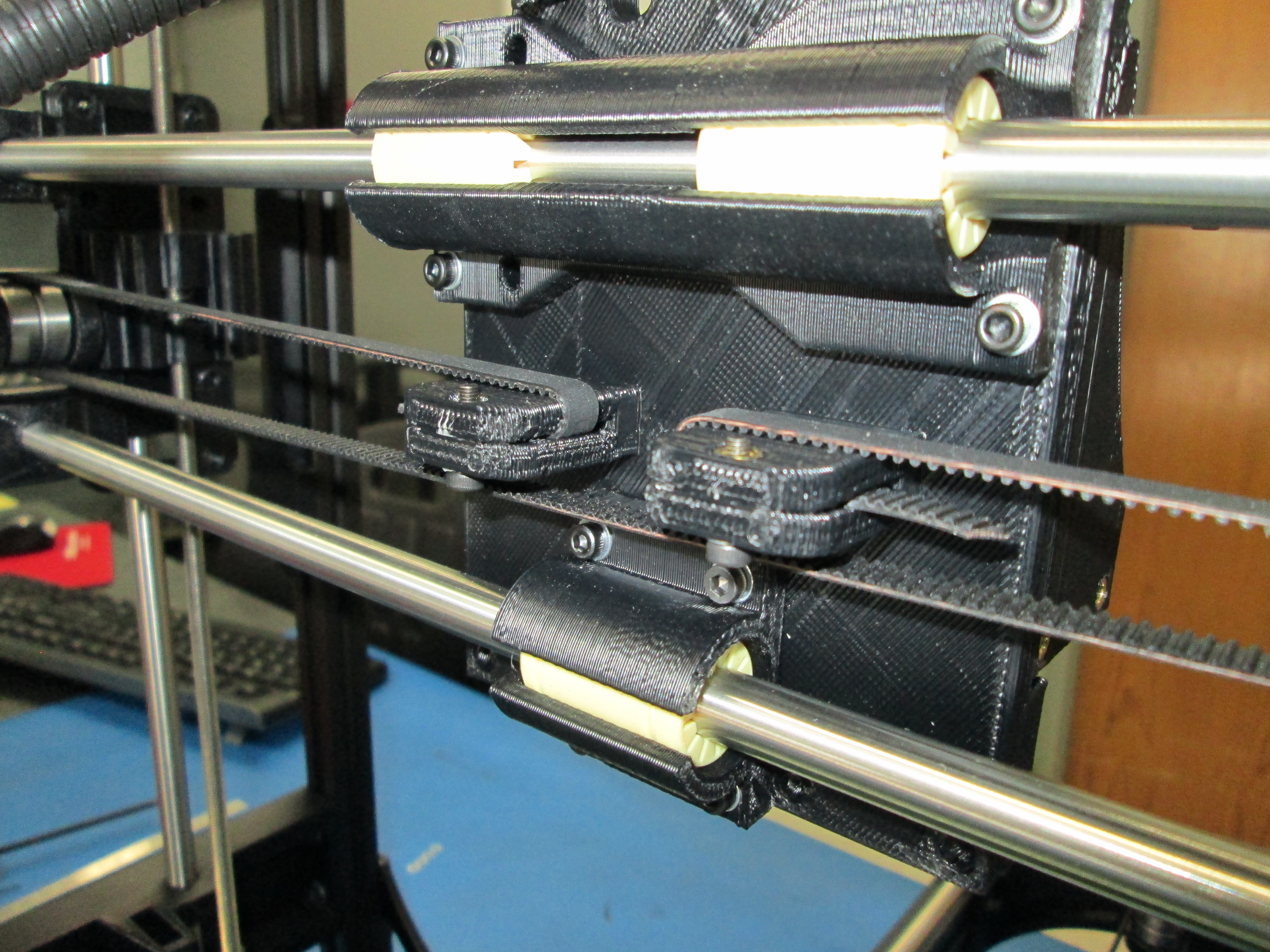
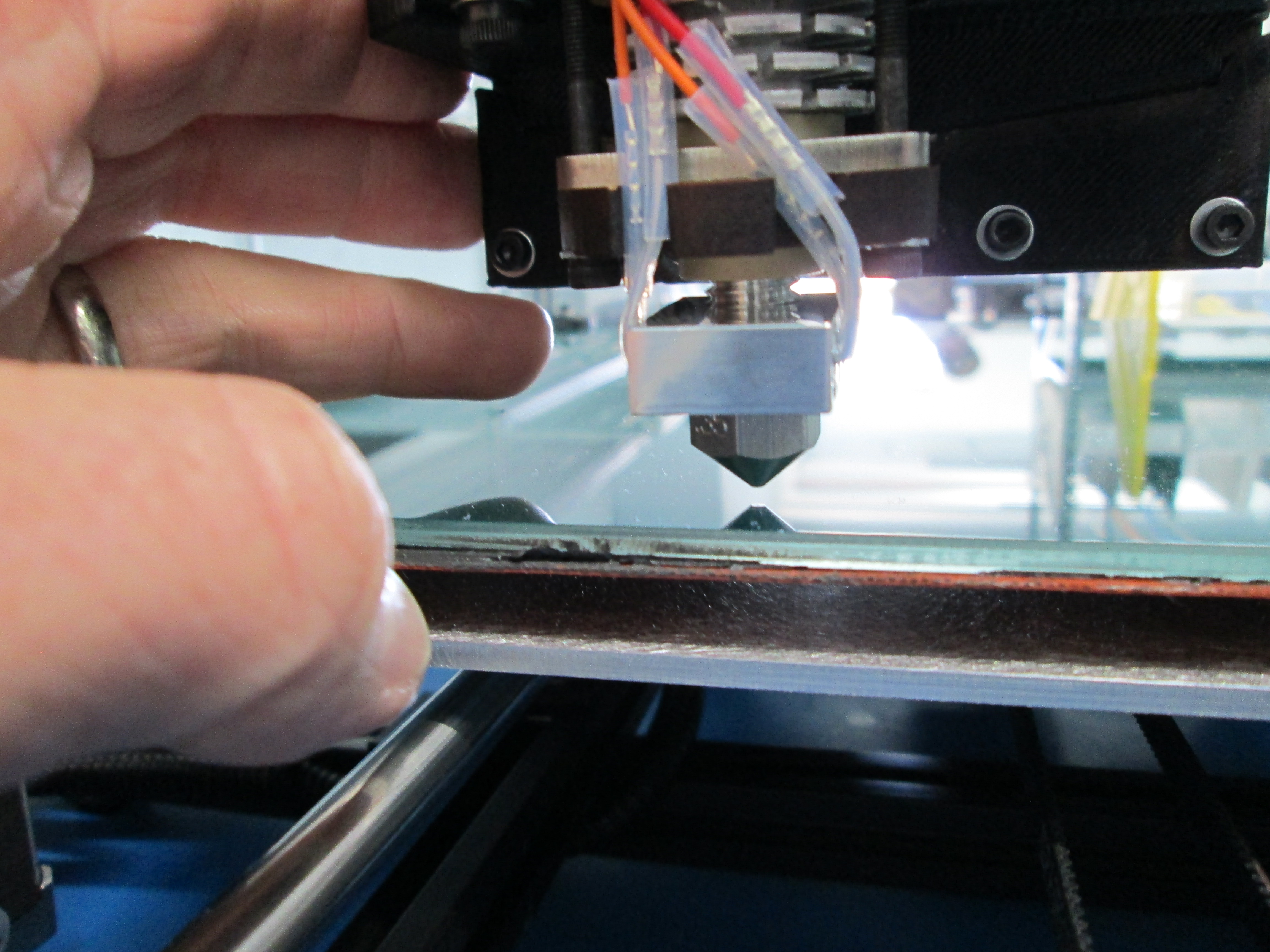
  • With the nozzle slightly above the heat bed, manually move the print head along the X axis eyeing the distance between the nozzle and the bed as you go.

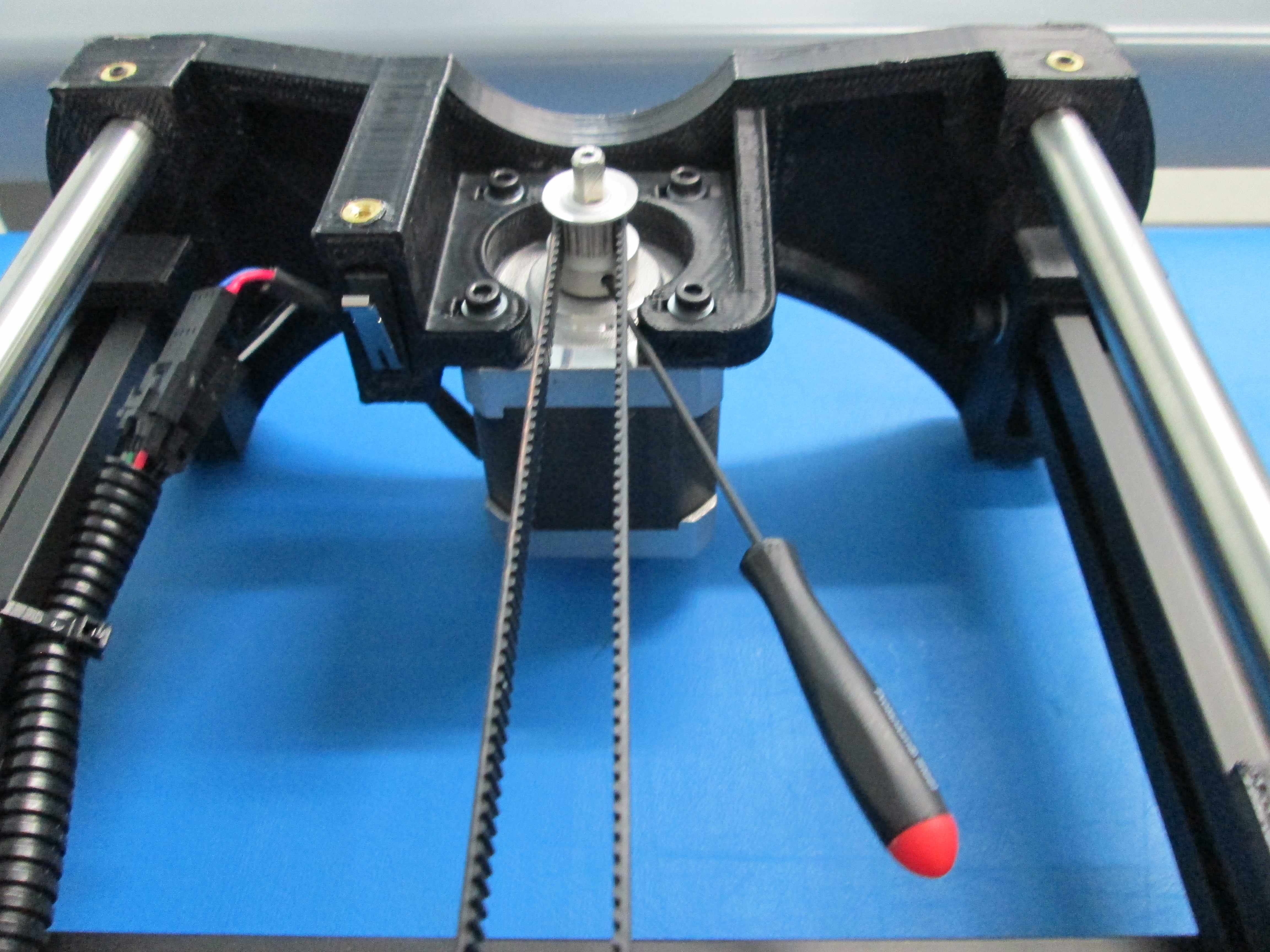
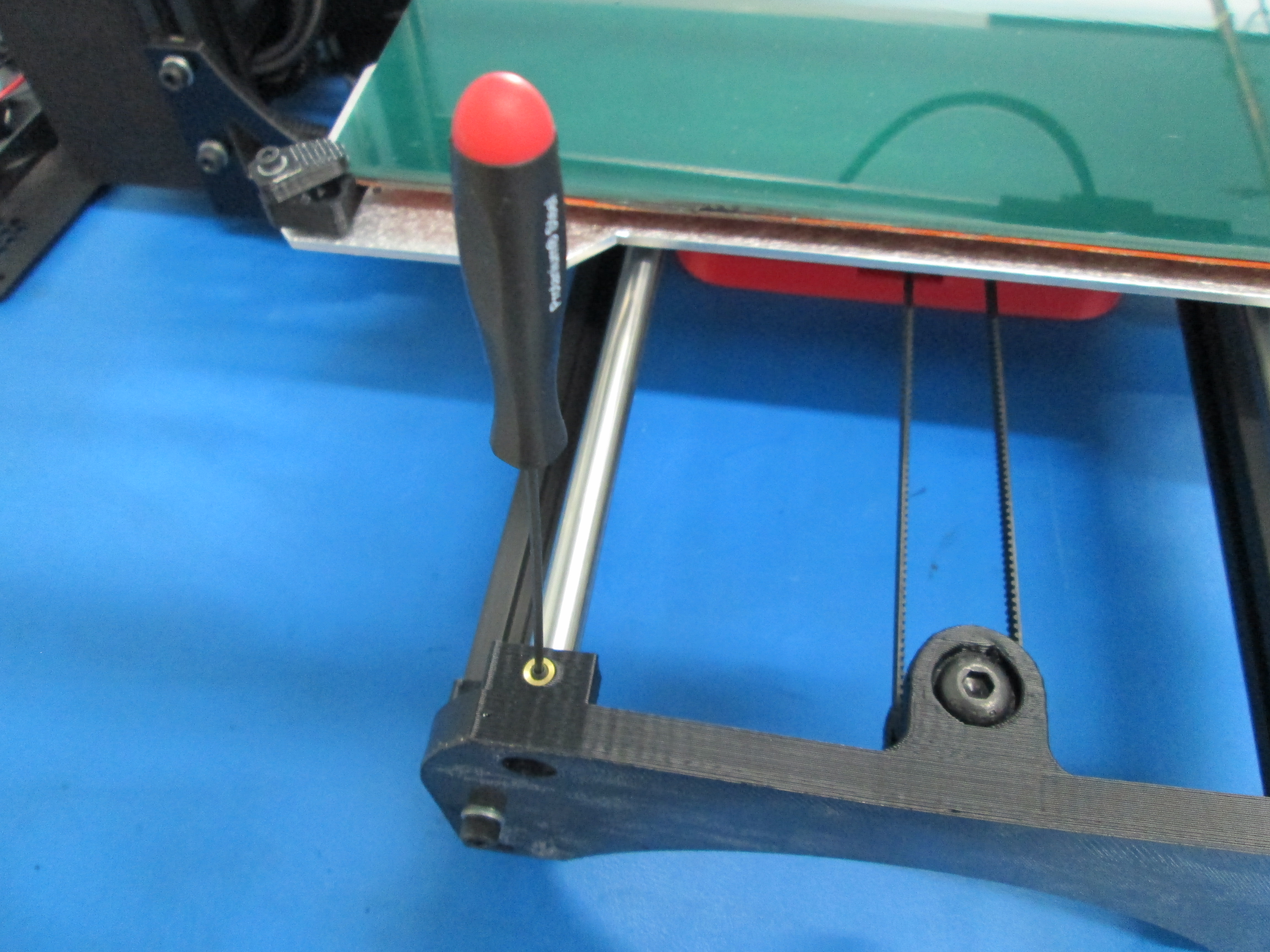
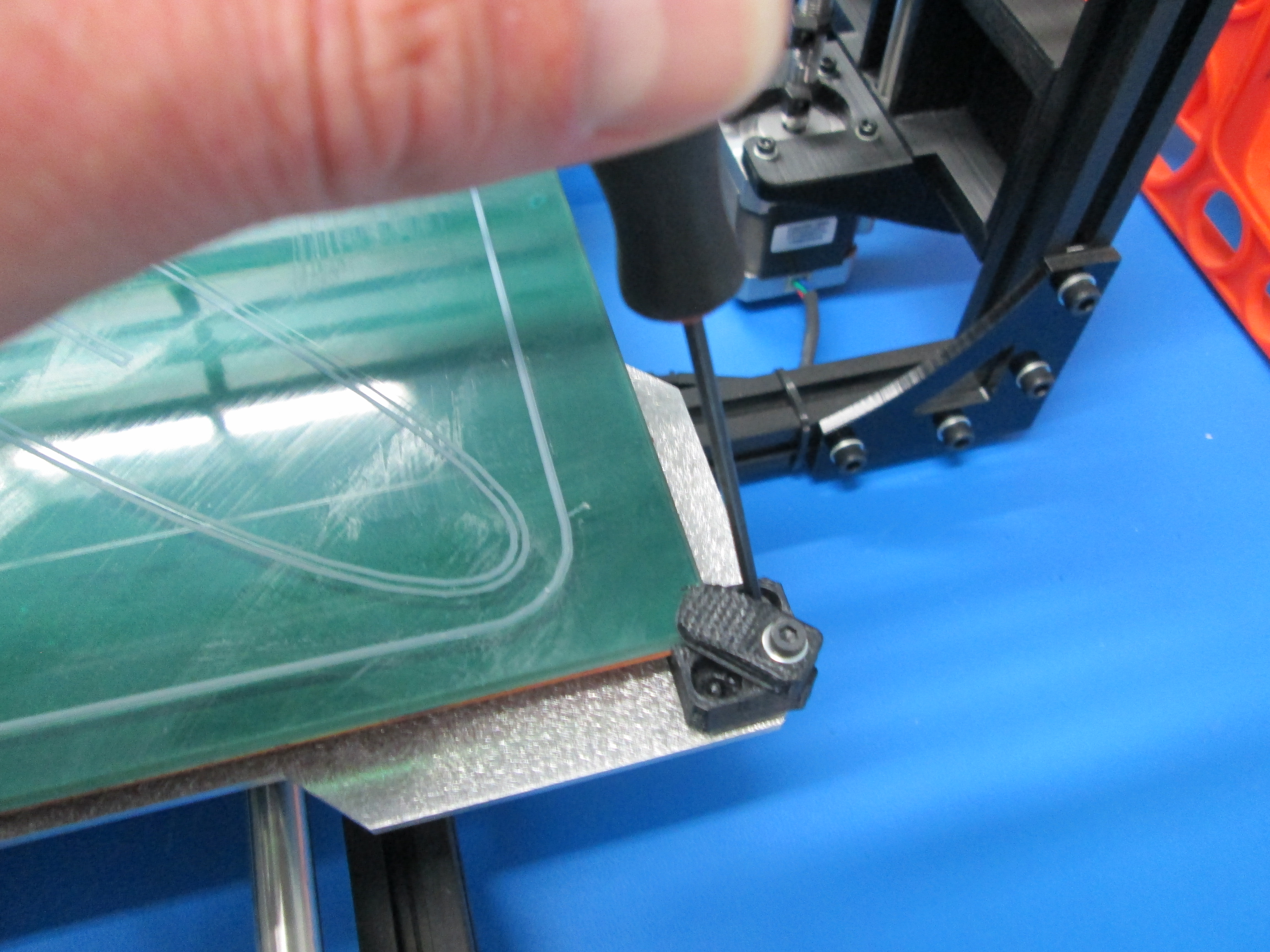
  • Adjust one drive rod by rotating it while holding the other stationary until the X axis is parallel to the bed.

  • Rough level the bed by checking the distance from front to back as well as side to side. Adjust the bed corner screws accordingly.

Begin with nozzle slightly above the bed
Check the distance as you move the print head
Adjust one drive rod while holding the other stationary

5 Calibrate Extruder

  • Apply LulzJuice to the heat bed prior to heating it up.

  • Connect Pronterface to the printer. Set the nozzle temperature to 230 degrees Celsius, set the heat bed to 85 degrees.

  • Raise the Z axis away from the heat bed and install filament in the extruder. Set the thumbscrews using the 10mm TL-FX0013 fixture.

  • After the nozzle has achieved the set point temperature for a couple of minutes, extrude filament in 20mm increments until the nozzle is primed.

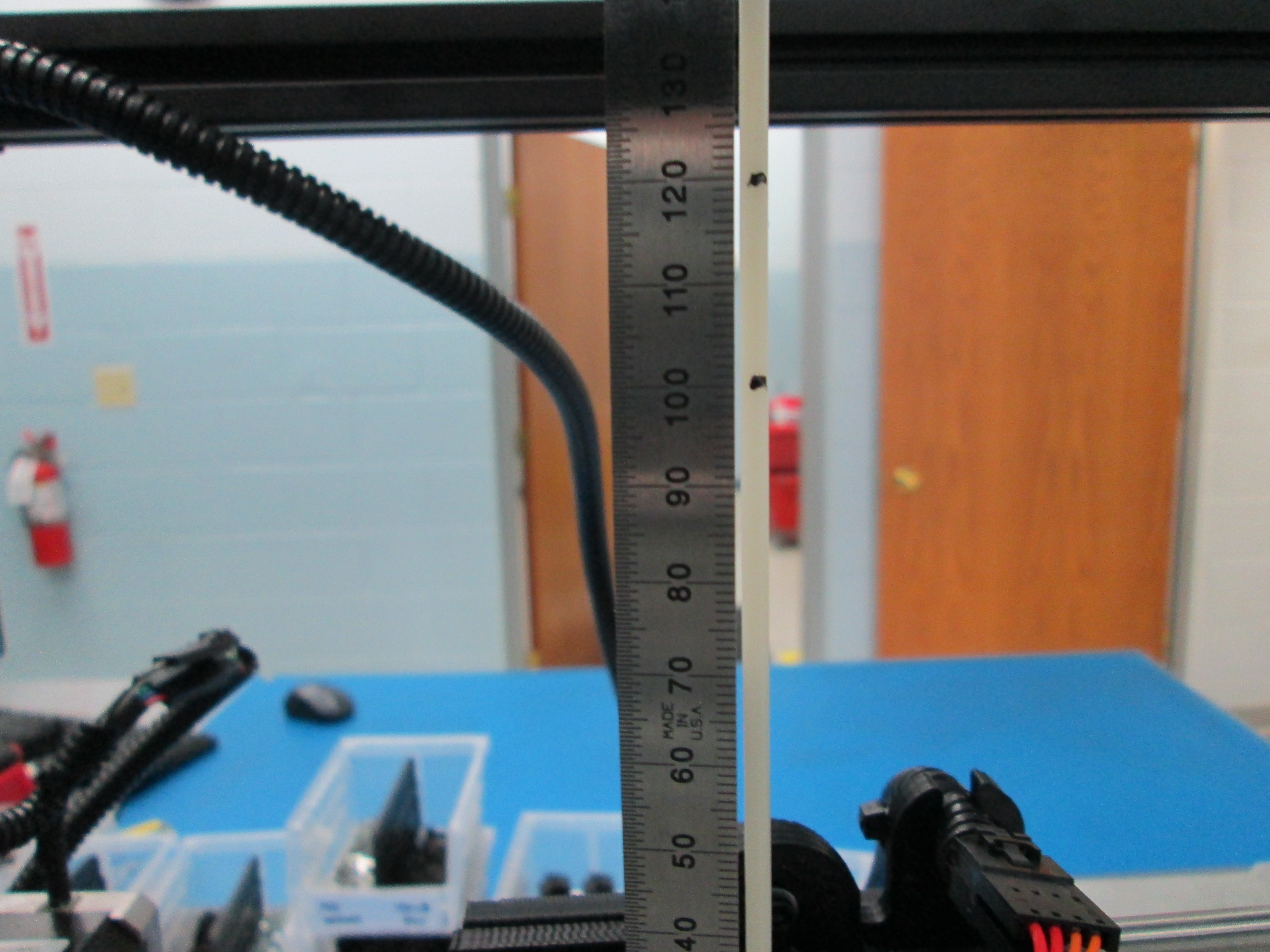
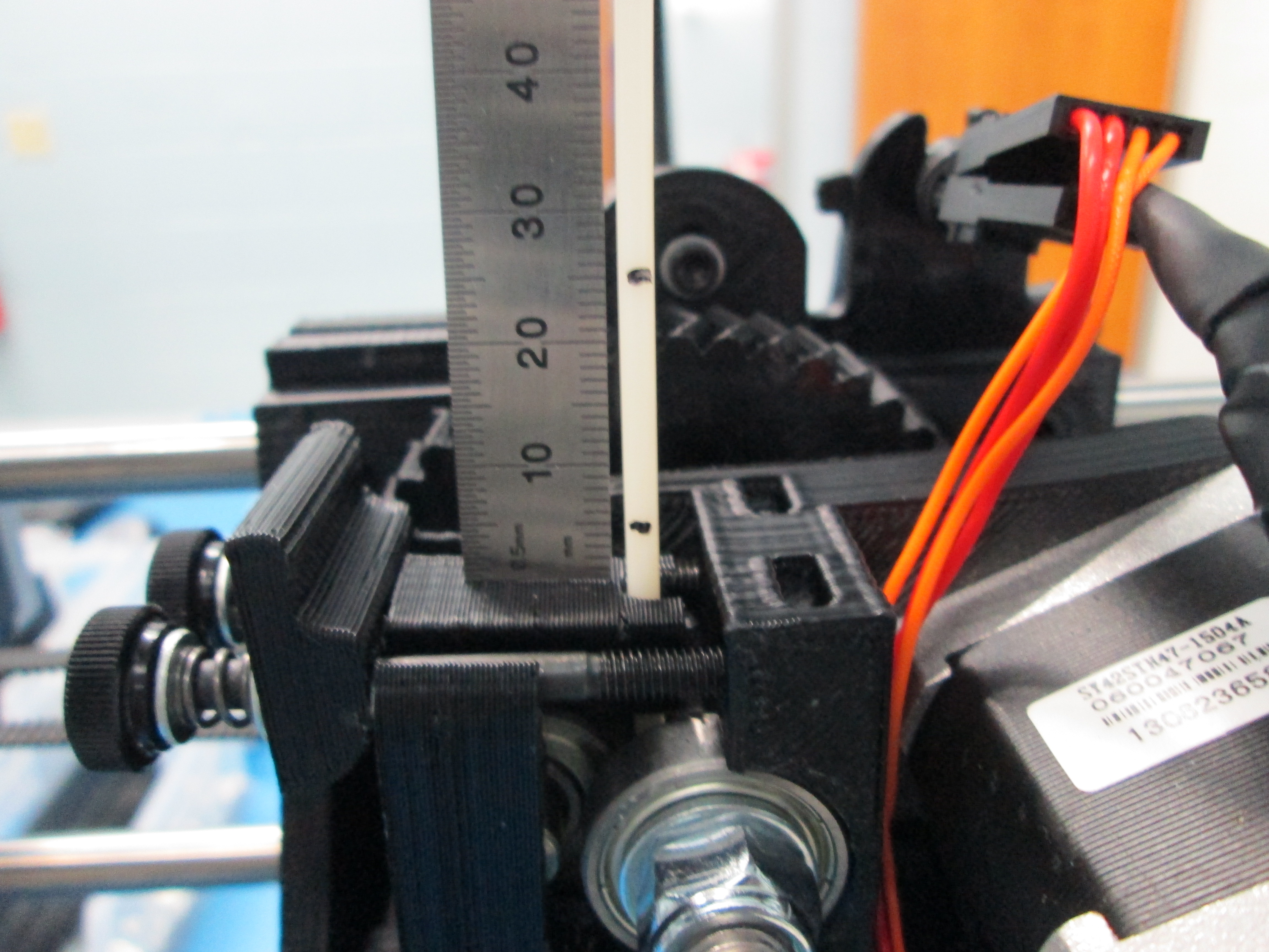
  • Using the 150mm ruler, mark the filament with the Sharpie at 100mm and 120mm above the extruder.

  • Ensure that Pronter is set to extrude 100mm of filament at 70mm/min for a .35 nozzle. Set Pronter to extrude 100mm of filament at 90mm/min for a .5 nozzle.

    • Click 'EXTRUDE' on Pronterface to begin the test.
    • After the extruder stops, measure the distance from the 100mm mark.
    • Calculate the number of steps to change using the formula (800 / X * 100) = Number of new steps.
    • Example: 800 / 95 * 100 = 842.
    • Modify the Arduino sketch in the Configuration.h file
    • Change the line #define DEFAULT_AXIS_STEPS_PER_UNIT {100.5,100.5,800,800} to reflect the new step number #define DEFAULT_AXIS_STEPS_PER_UNIT {100.5,100.5,800,842}.
  • Repeat the procedure until the extruded distance equals 100mm twice.

Marking the filament at 100 and 120mm
Reading after 100mm extrusion.

6 Bed Leveling

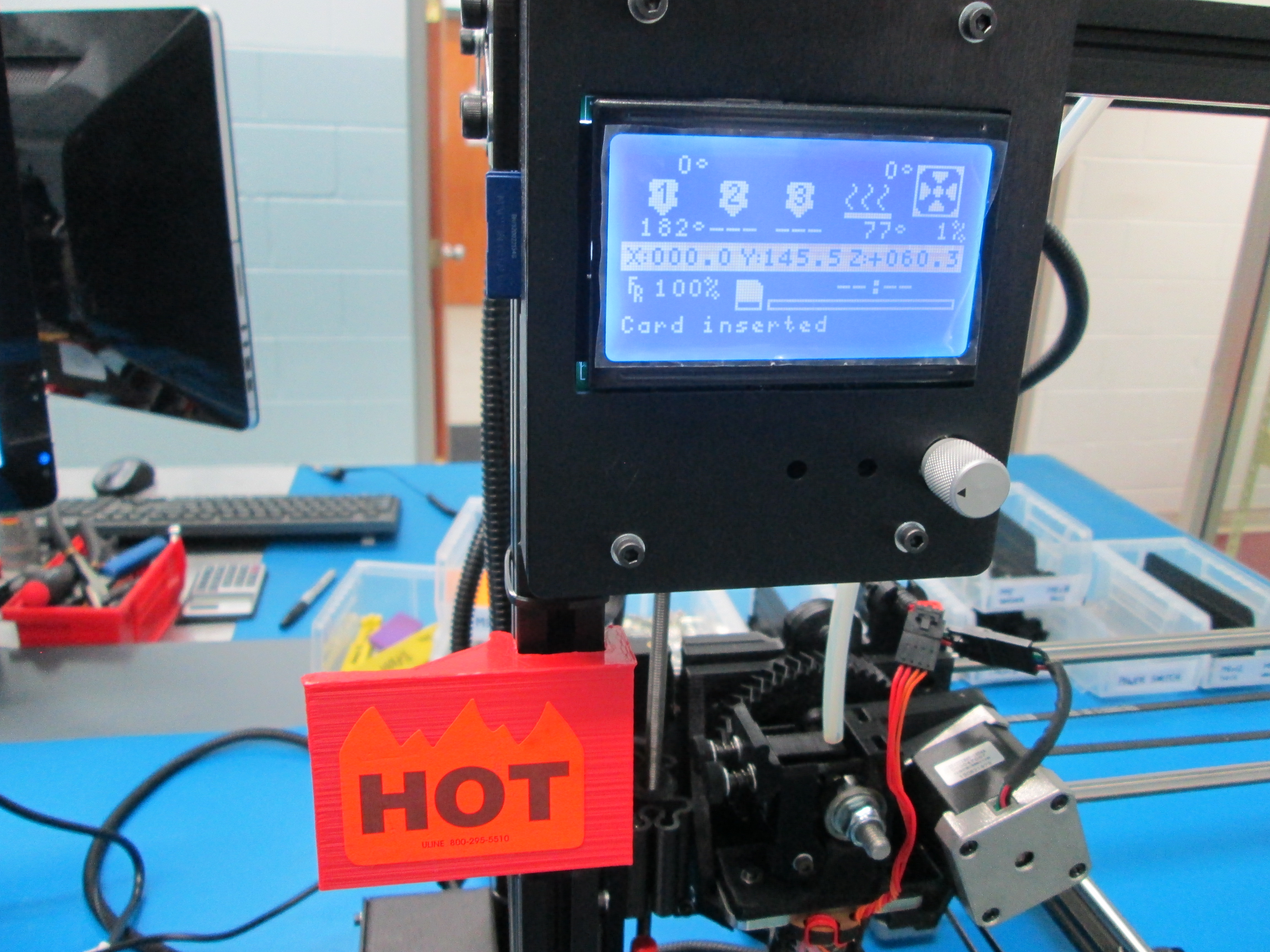
  • Add a HOT placard to the printer and install the calibration SD card.

  • Ensure that Pronterface is connected to the printer and the nozzle and bed temperatures are set.

  • Click 'LOAD FILE' in Pronter and navigate to 'bed_calibration.gcode'

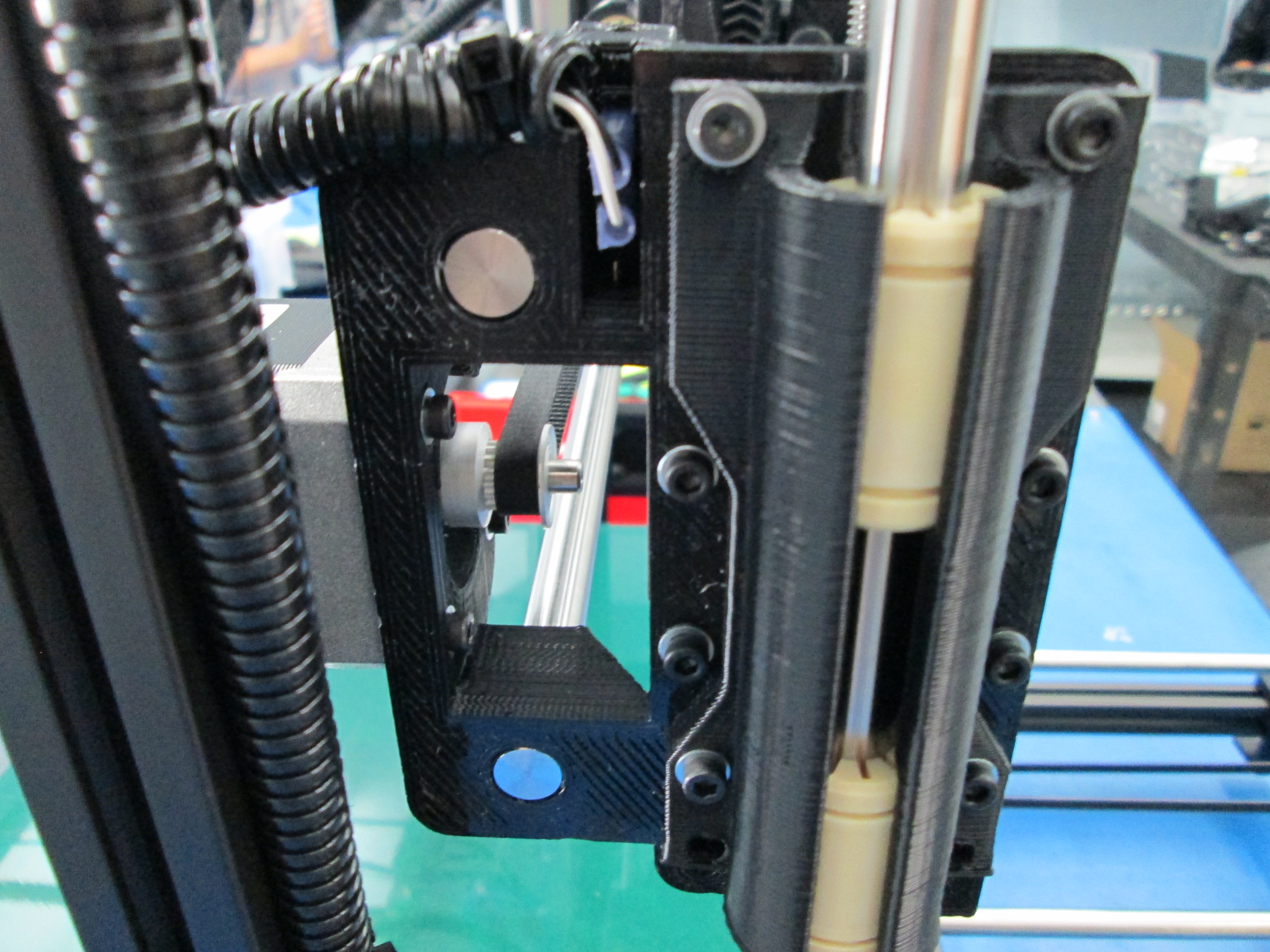
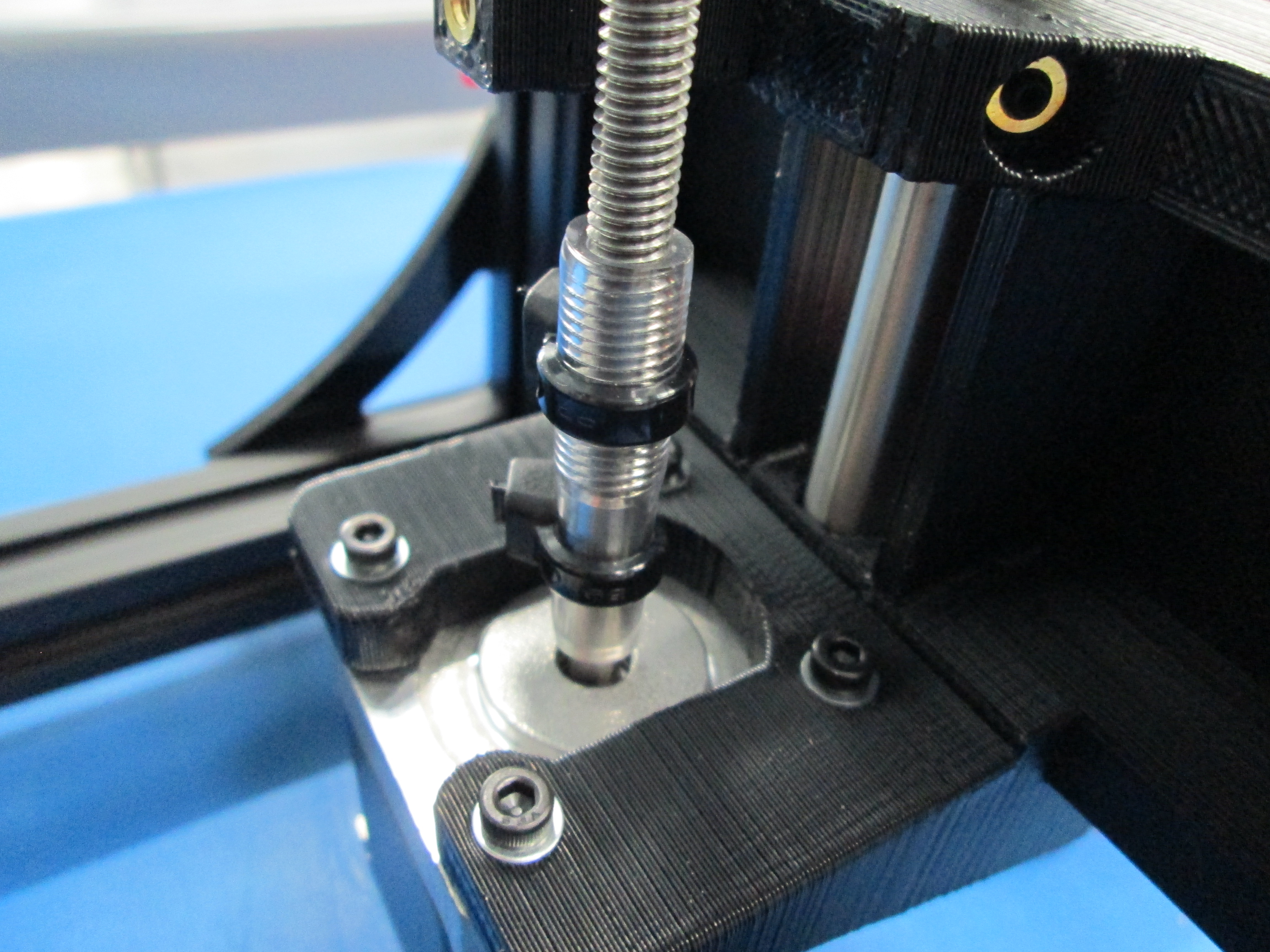
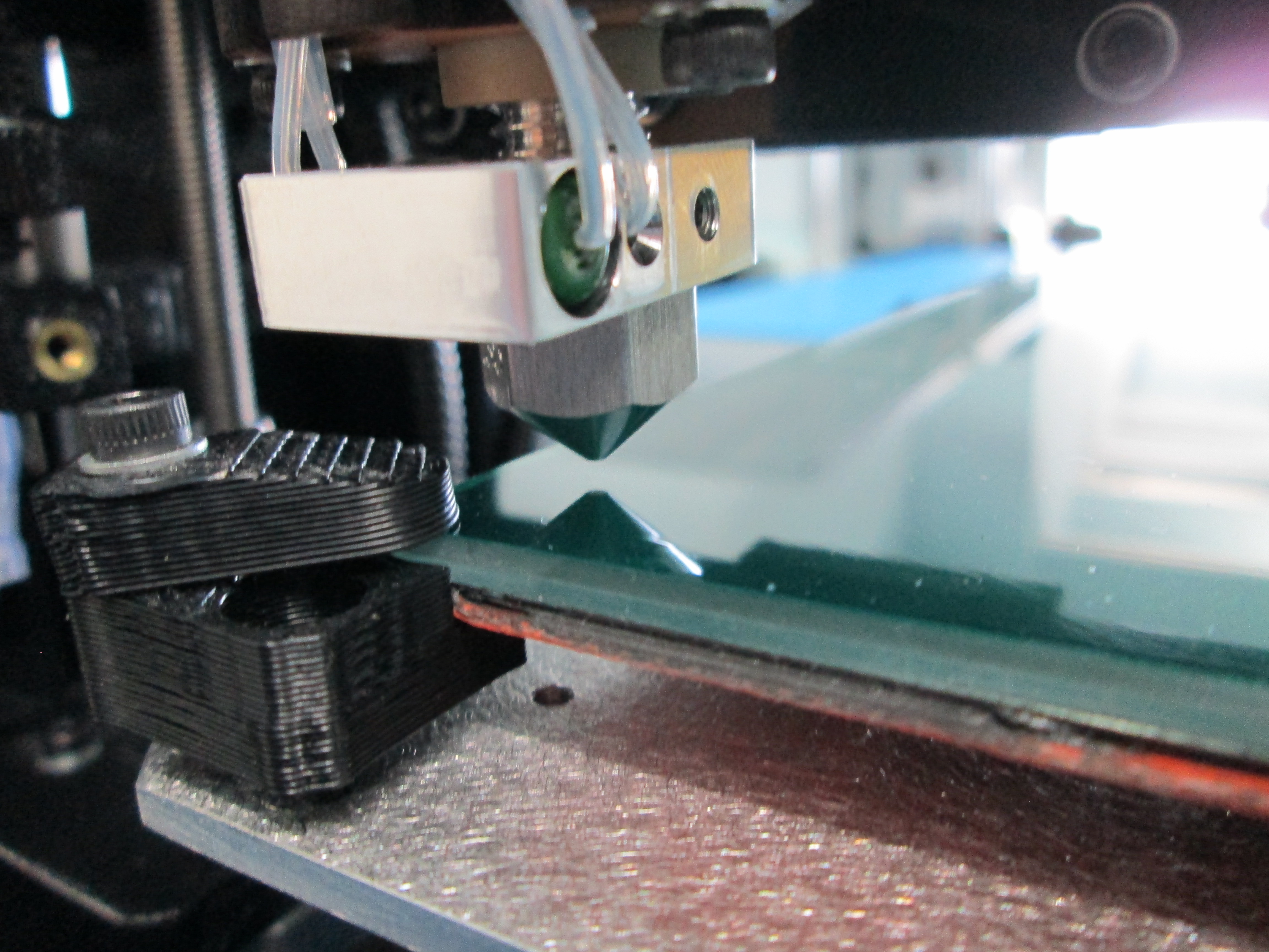
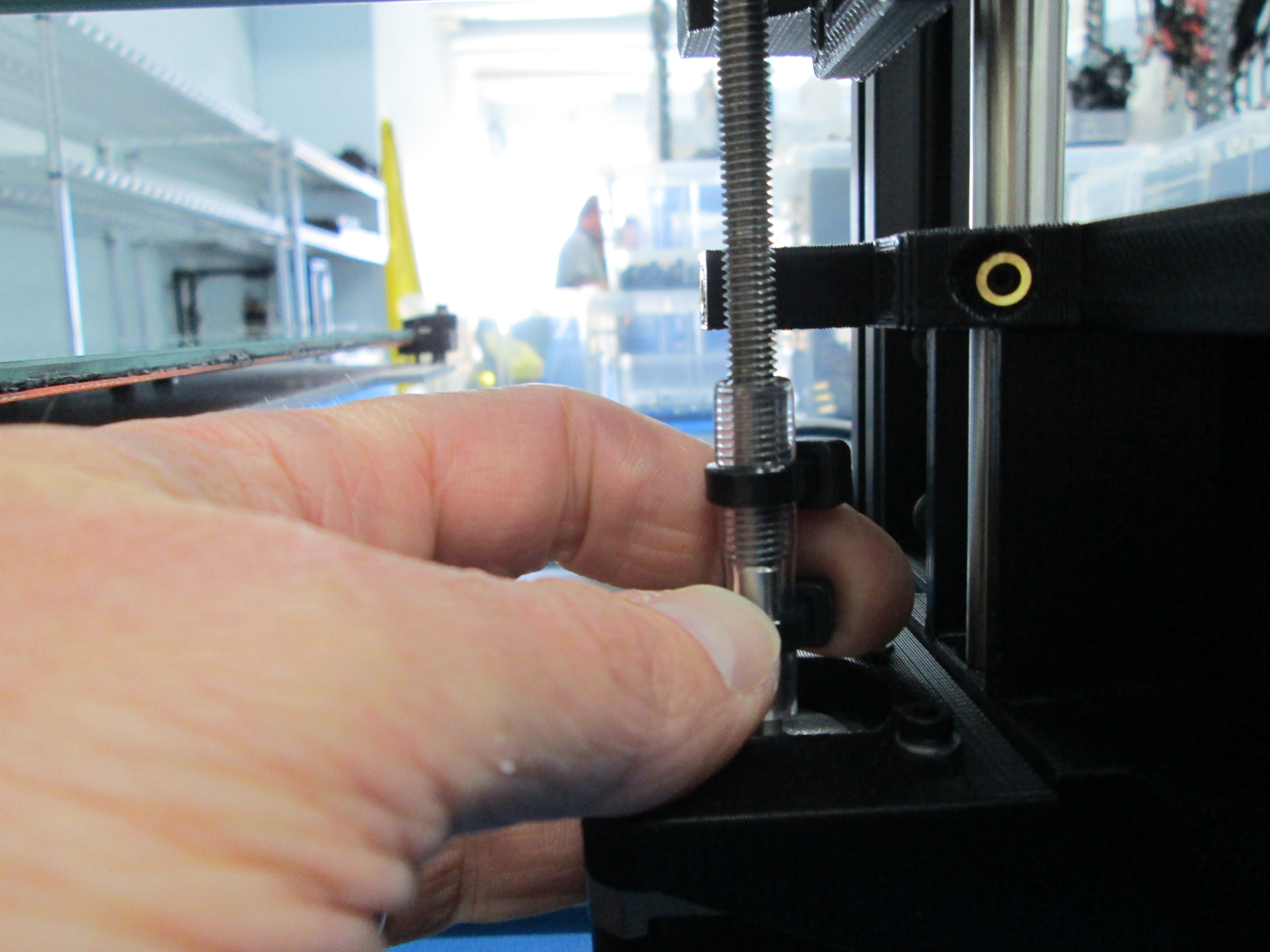
  • Click the home button on the bottom left of the axis controller. Check the distance between the nozzle and the heat bed when the Z axis is in the home position. Adjust the Z limit screw until the nozzle is just slightly (approximately .5mm) above the heat bed.

  • Click 'PRINT' in Pronterface.

  • Examine the resulting print. The extrusion should be uniform from side to side and front to back and approximately 1mm wide.

  • Adjust the heat bed screws in small increments to achieve the desired result. Back the bed corner screws out to raise a corner of the bed, turn them in to lower a corner.

  • If the print is uniform across the bed, the bed is leveled. Otherwise, gently remove the print with a clam knife, adjust the bed corners and repeat the process until the print is uniform.

HOT placard and SD card installed
Loading bed calibration file
Bed calibration file loaded in Pronterface
Adjusting a bed corner to level the bed
Uniform print after leveling bed

7 Move to Final Testing

  • Disconnect printer from Pronterface.

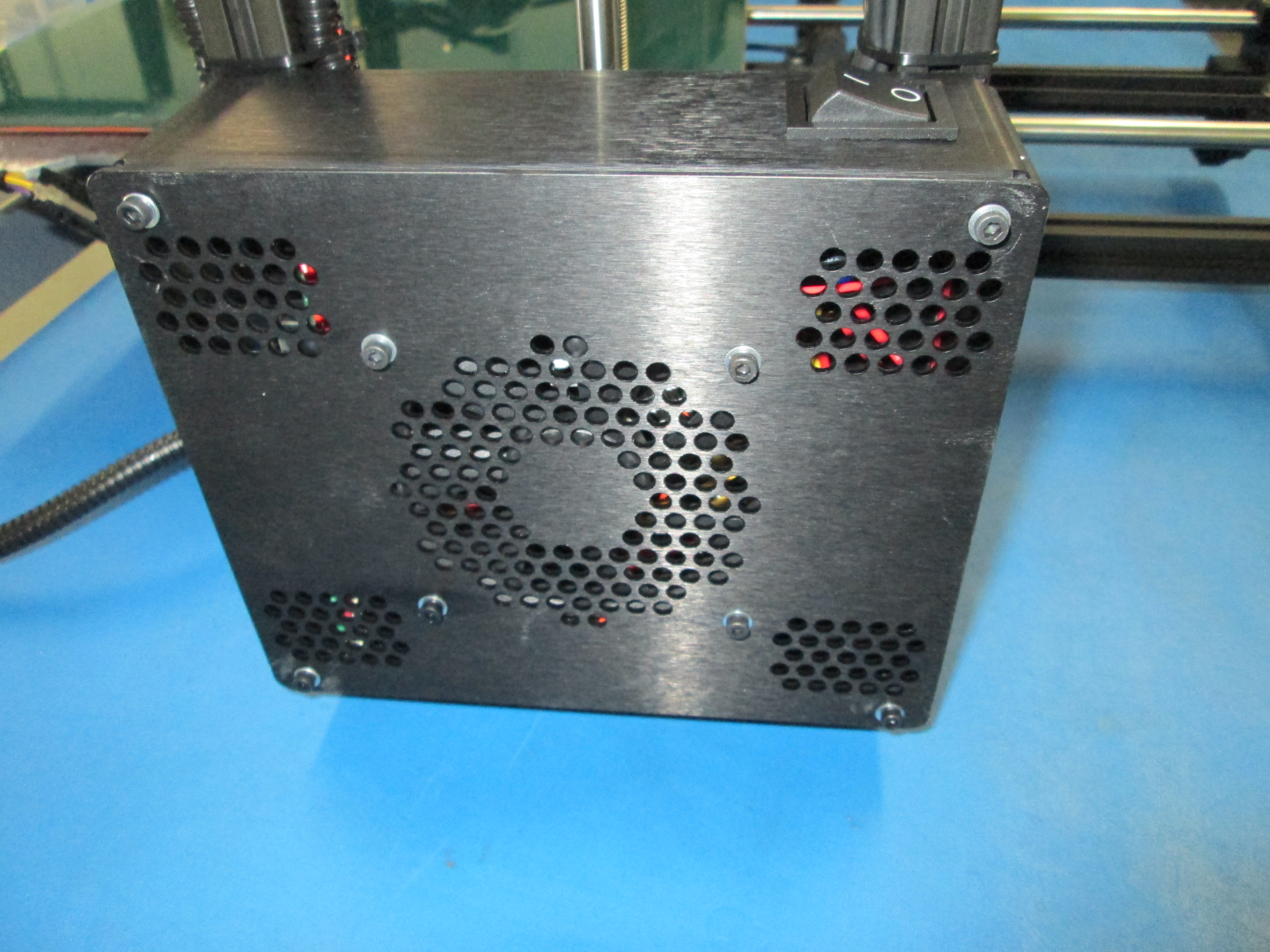
  • Switch off power and remove power and USB cords.

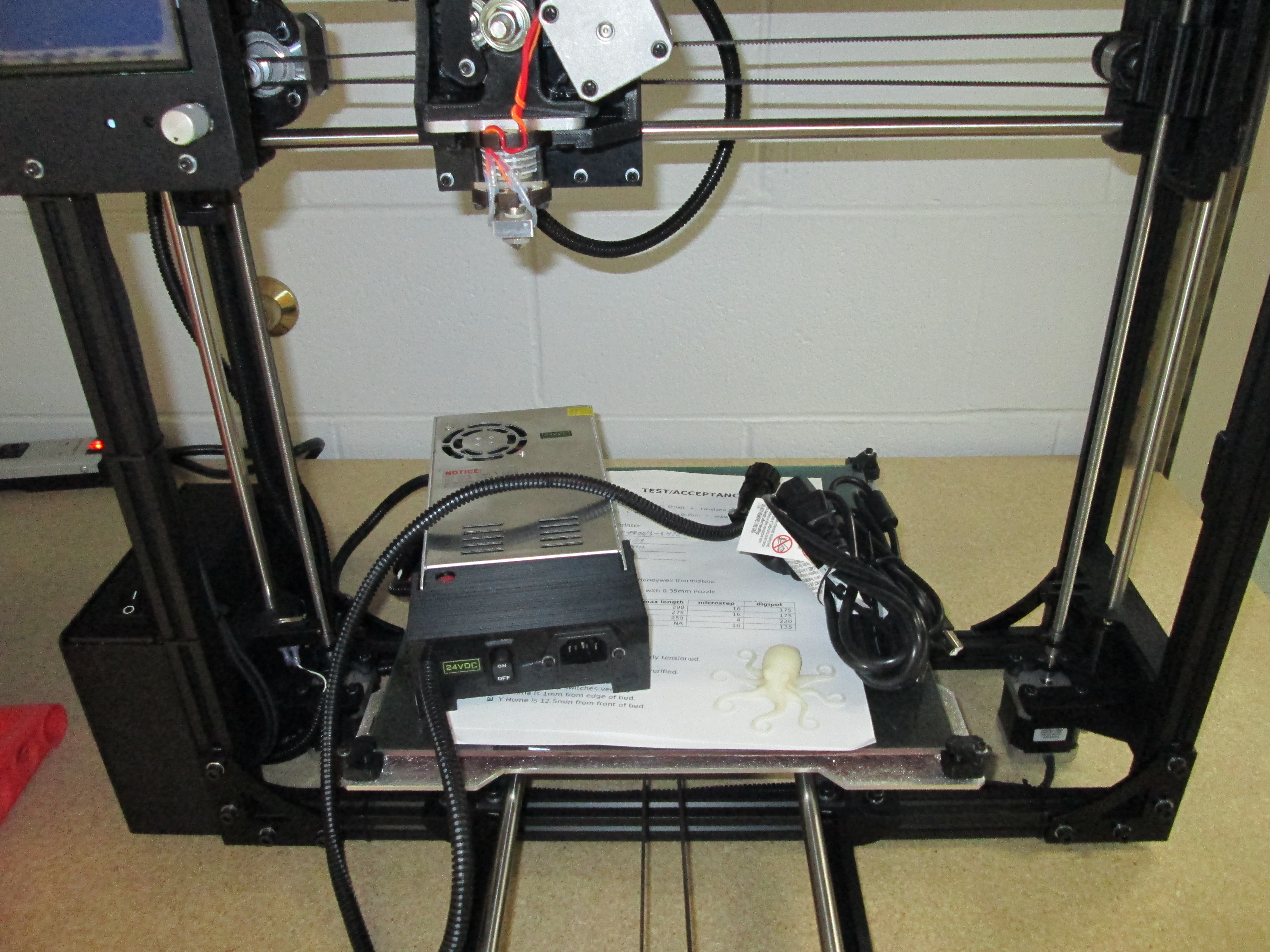
  • Move the printer, power supply and cords to the staging area. Keep the paperwork with the printer.

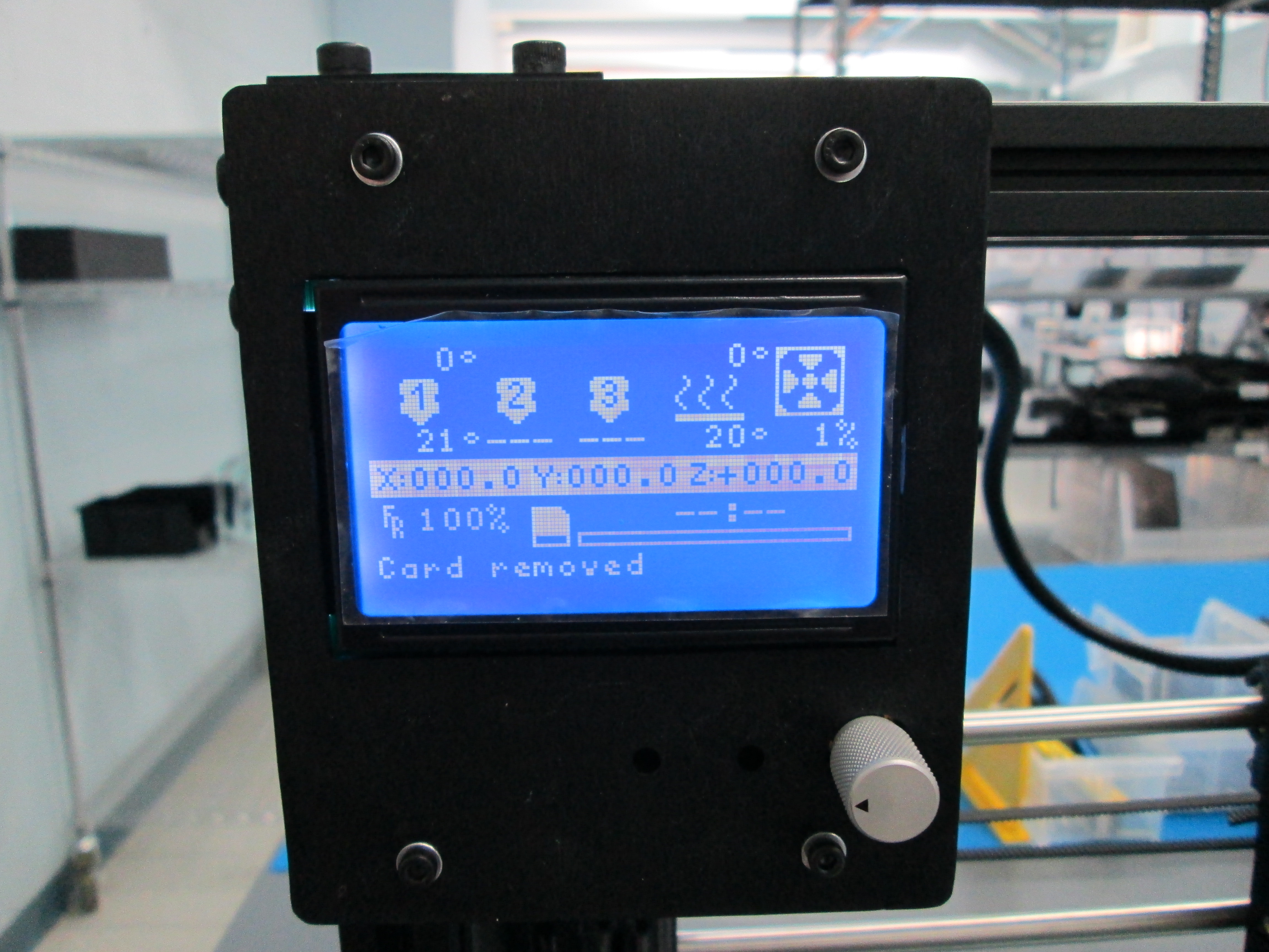
  • Reconnect the power and turn the printer on. Select 'Print From SD'' from the menu, then select 'burnin.gcode'.

  • Once bearing burn in is complete, reapply LulzJuice to the heat bed.

  • From the LCD menu, select 'Preheat ABS' to set the temperatures.

  • Once the temperatures on the nozzle and be are achieved, select 'PRINT FROM SD' on the LCD menu.

  • Select 'OCTO18-0.9.9.gcode' from the menu to print the calibration octopus. Note: the printer may have settled during bearing break-in and the Z limit switch may need adjusted to print a good octopus.

Printing octopus bottom layer
Octopus after several layers

8 Move the printer to shipping

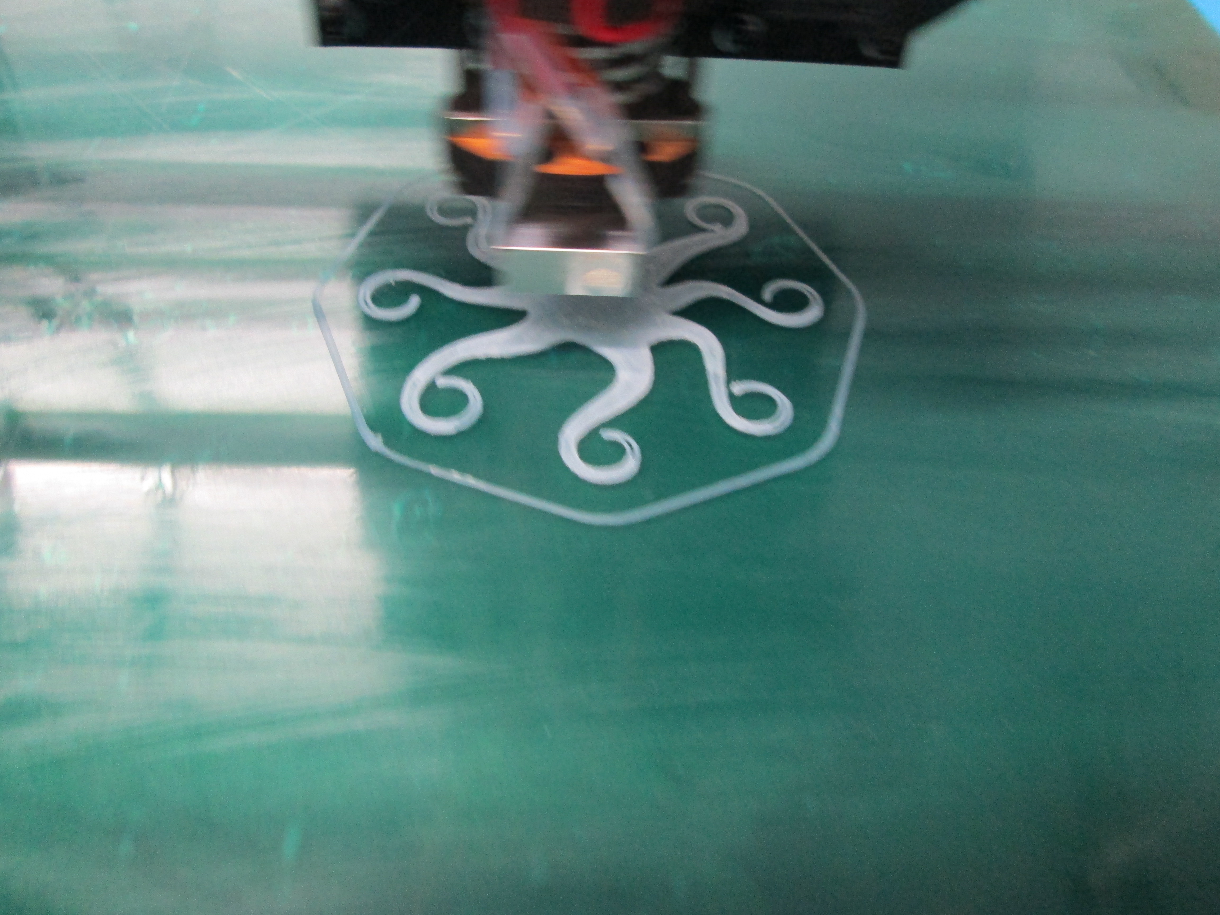
  • After successfully completing the bearing burn-in and printing a quality octopus, the printer is ready to ship.

    • X and Y belt tensions may loosen during bearing burn in and octopus printing. Re-check the belt tensions.
    • REMOVE THE CALIBRATION SD CARD and the HOT placard.
    • Ensure that both the Quality Checklist and Test/Acceptance Record are completed.
    • Enter the printer information in the Master Build Log.
    • Gather the Test/Acceptance Record, Quality Checklist, power supply, power cord, USB cord and printer. Move all components to the shipping area.
Complete the Master Build Log before moving the printer.
Gather all components to ship.
Done! Take me home