Open HardwareAssembly Instructions
Guides for installation and assembly of the LulzBot line of products made by FAME 3D LLC.
Guides for installation and assembly of the LulzBot line of products made by FAME 3D LLC.
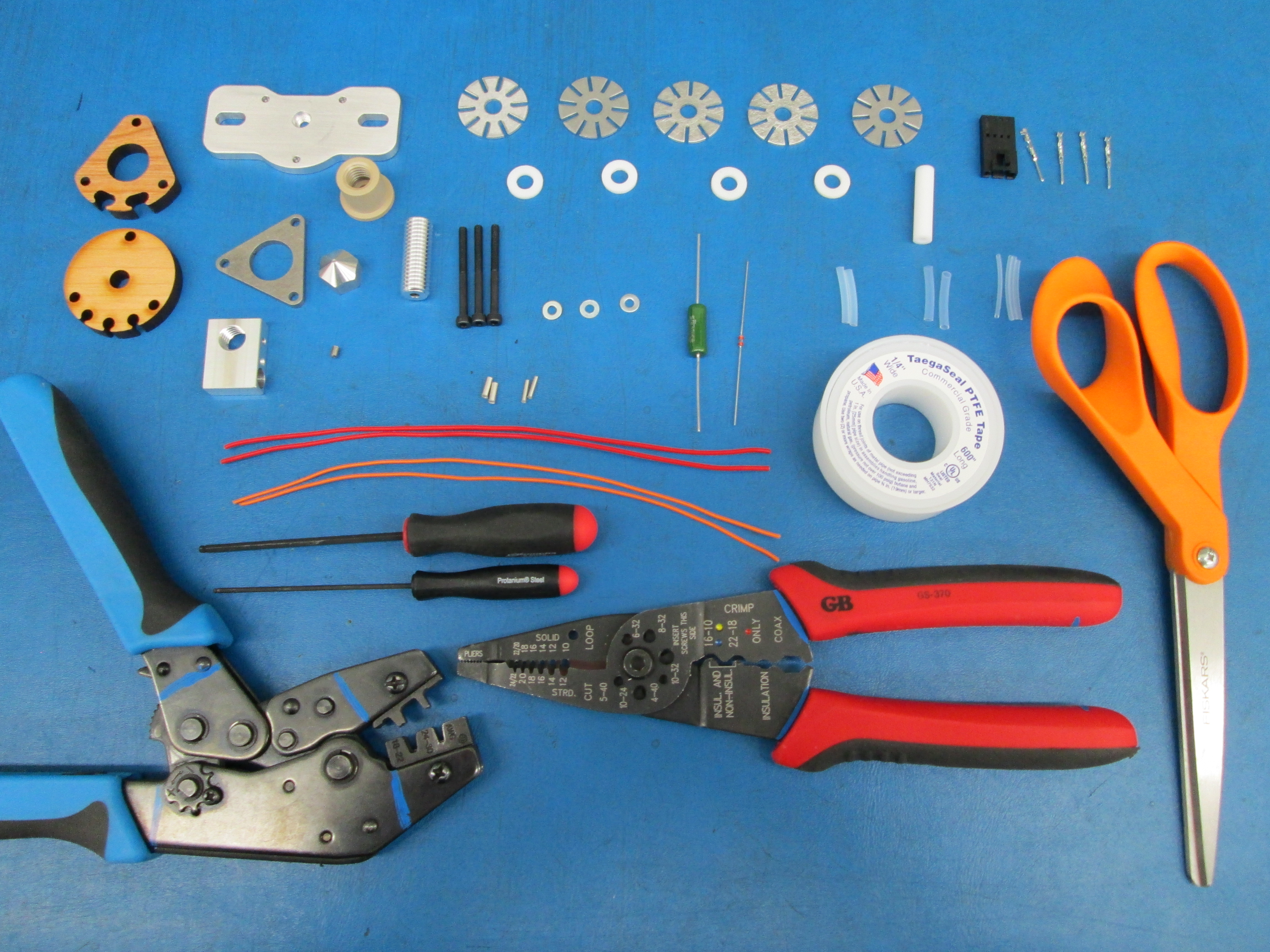
Tools required
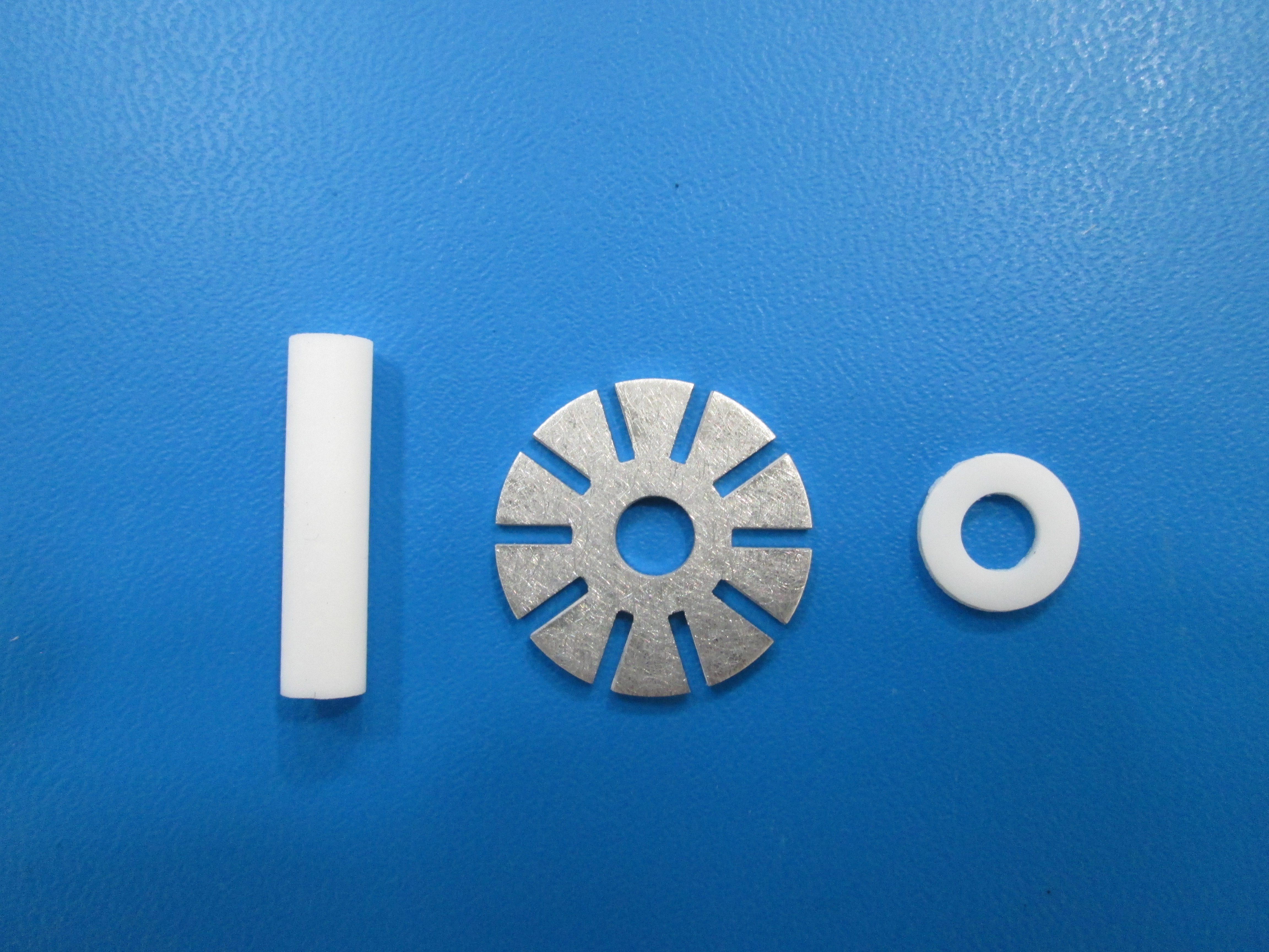
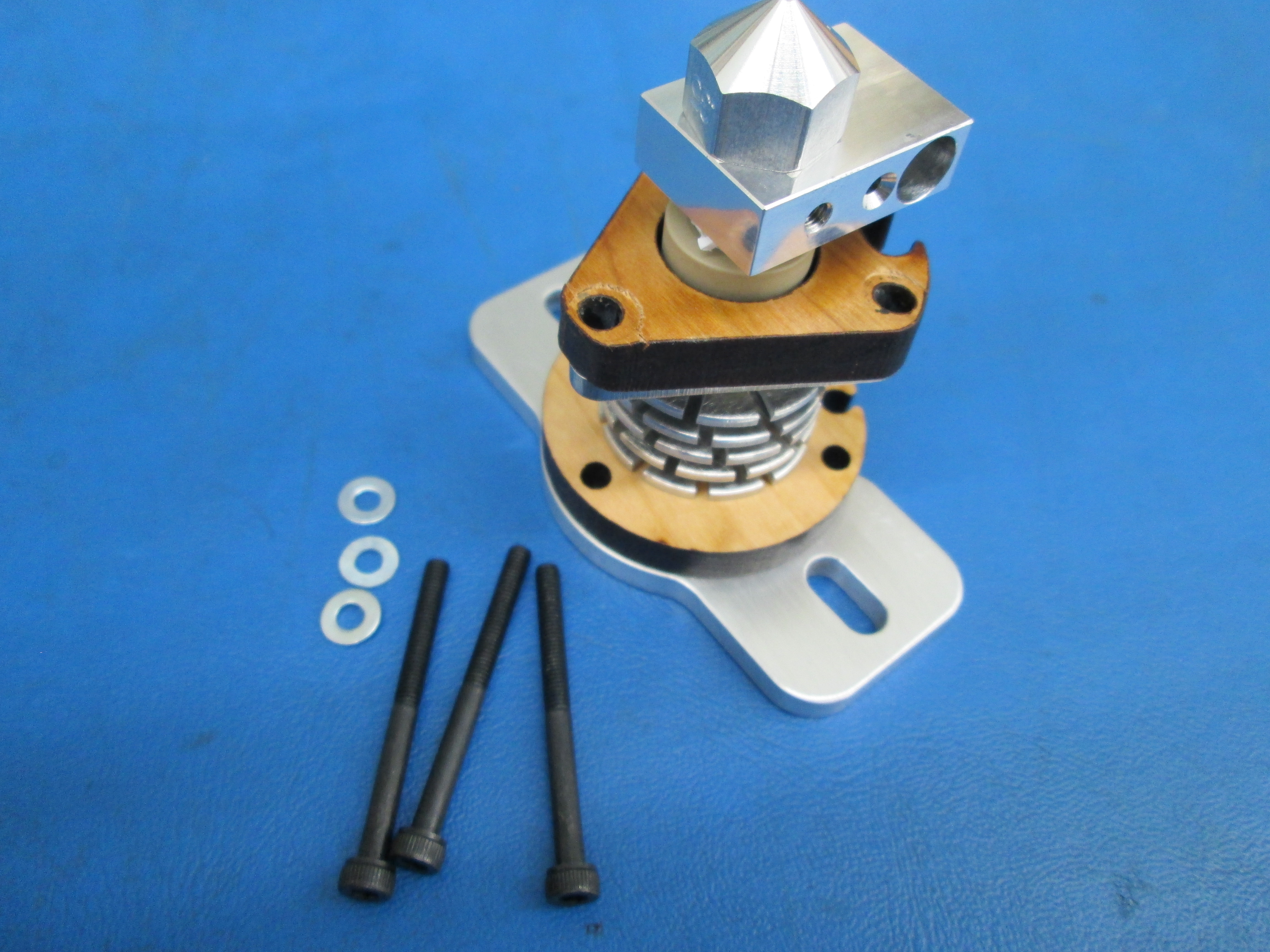
Parts required
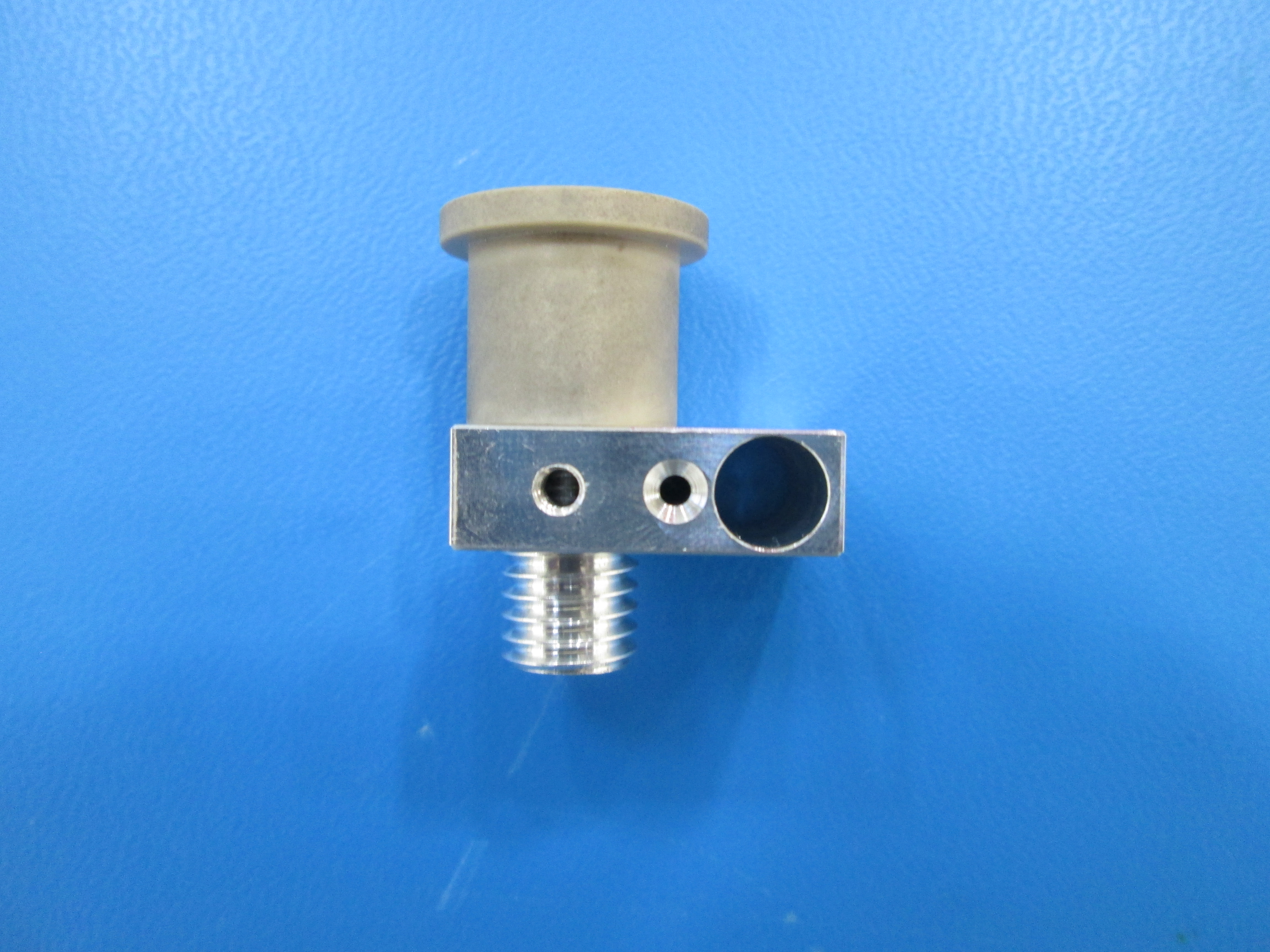
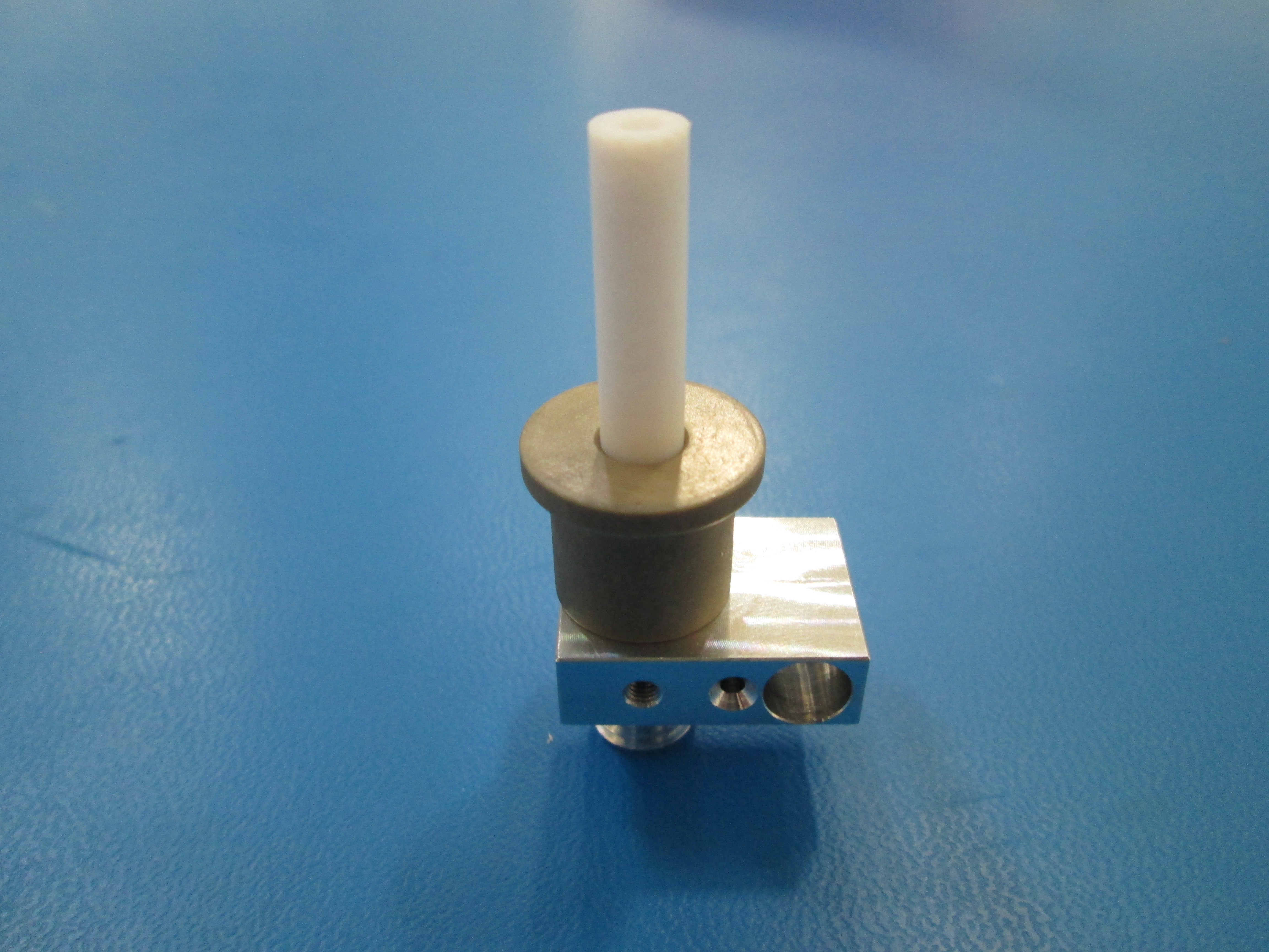
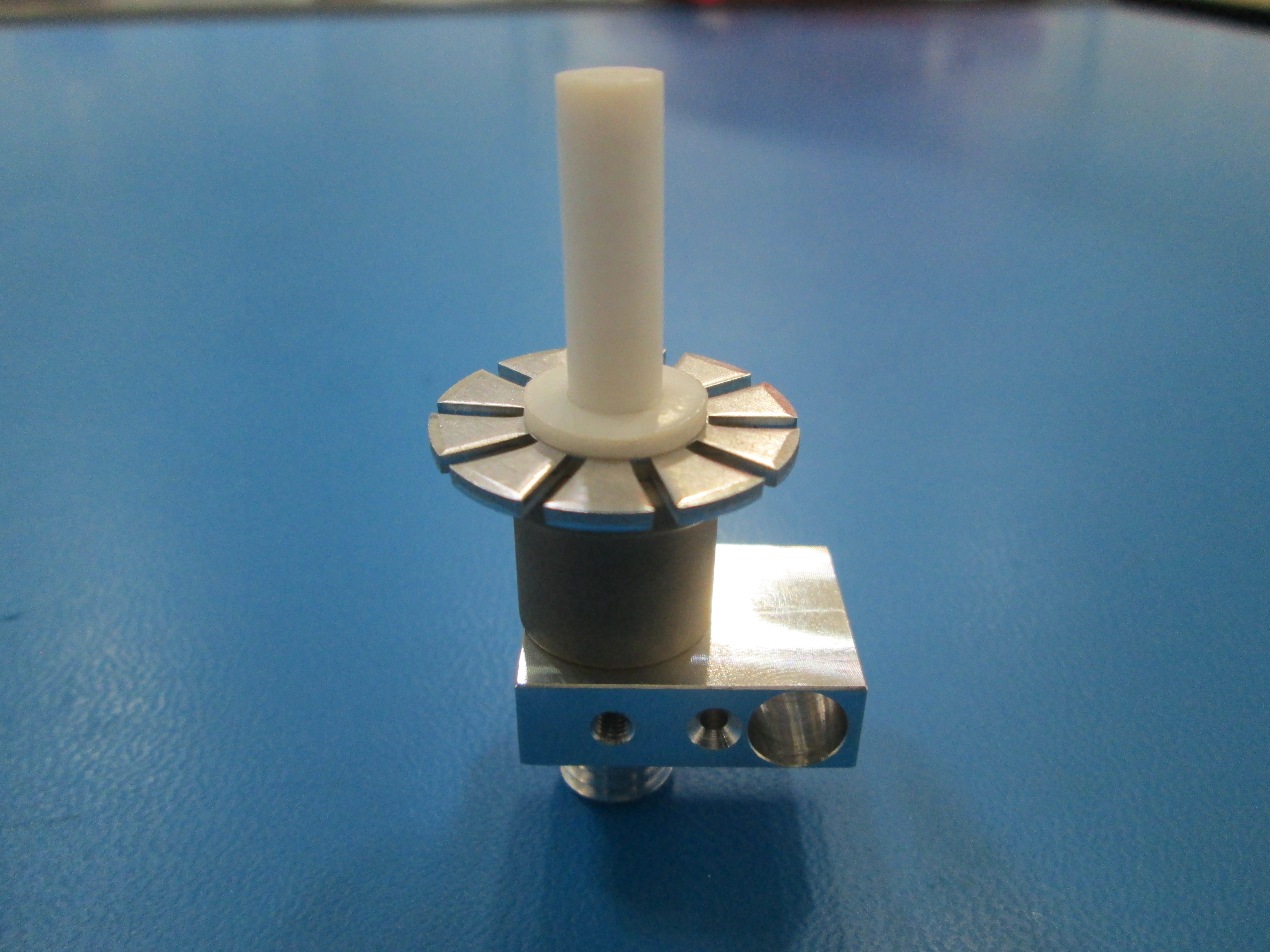
Insert the PTFE tube for filament into the heat sink construction fixture
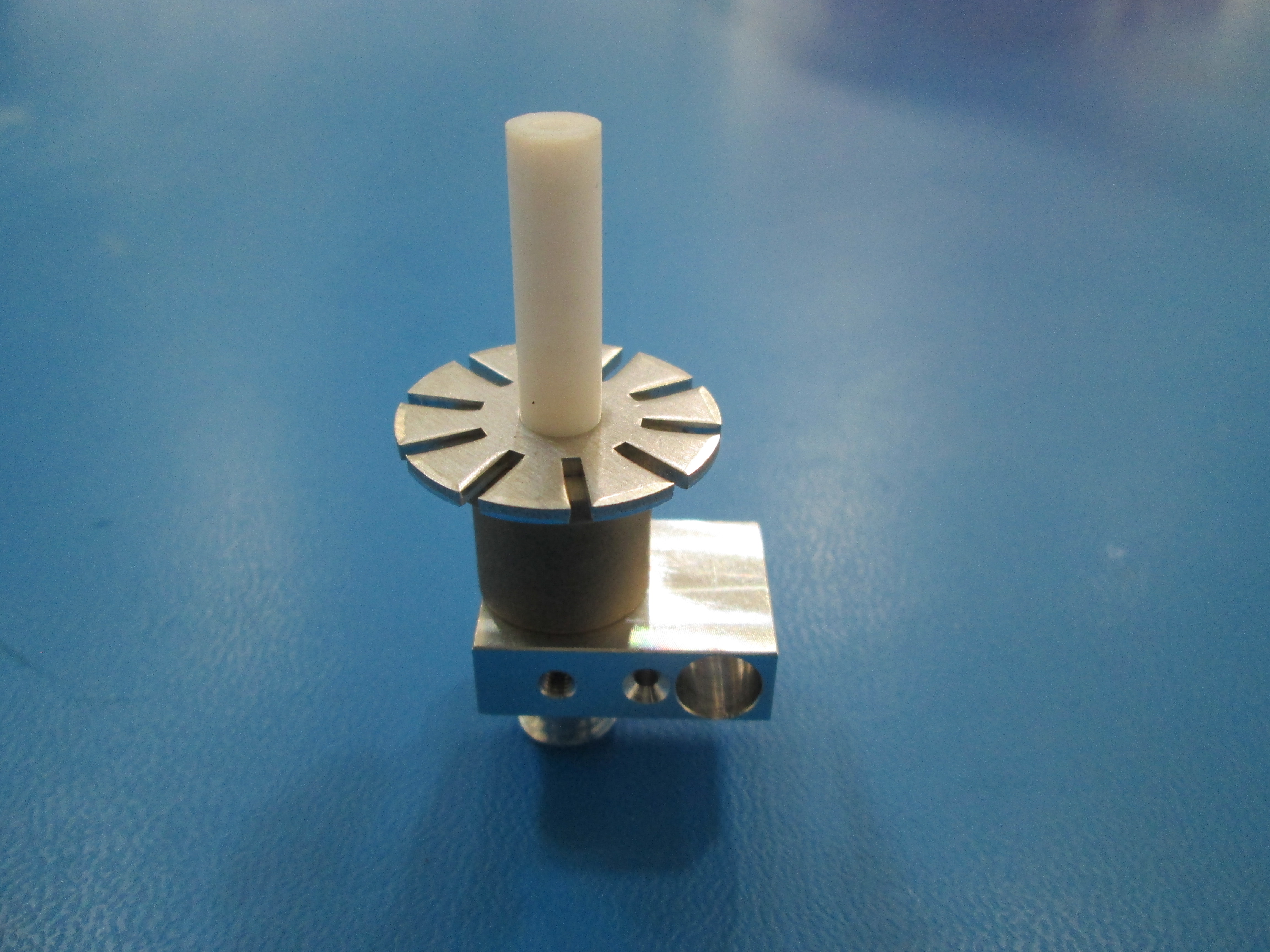
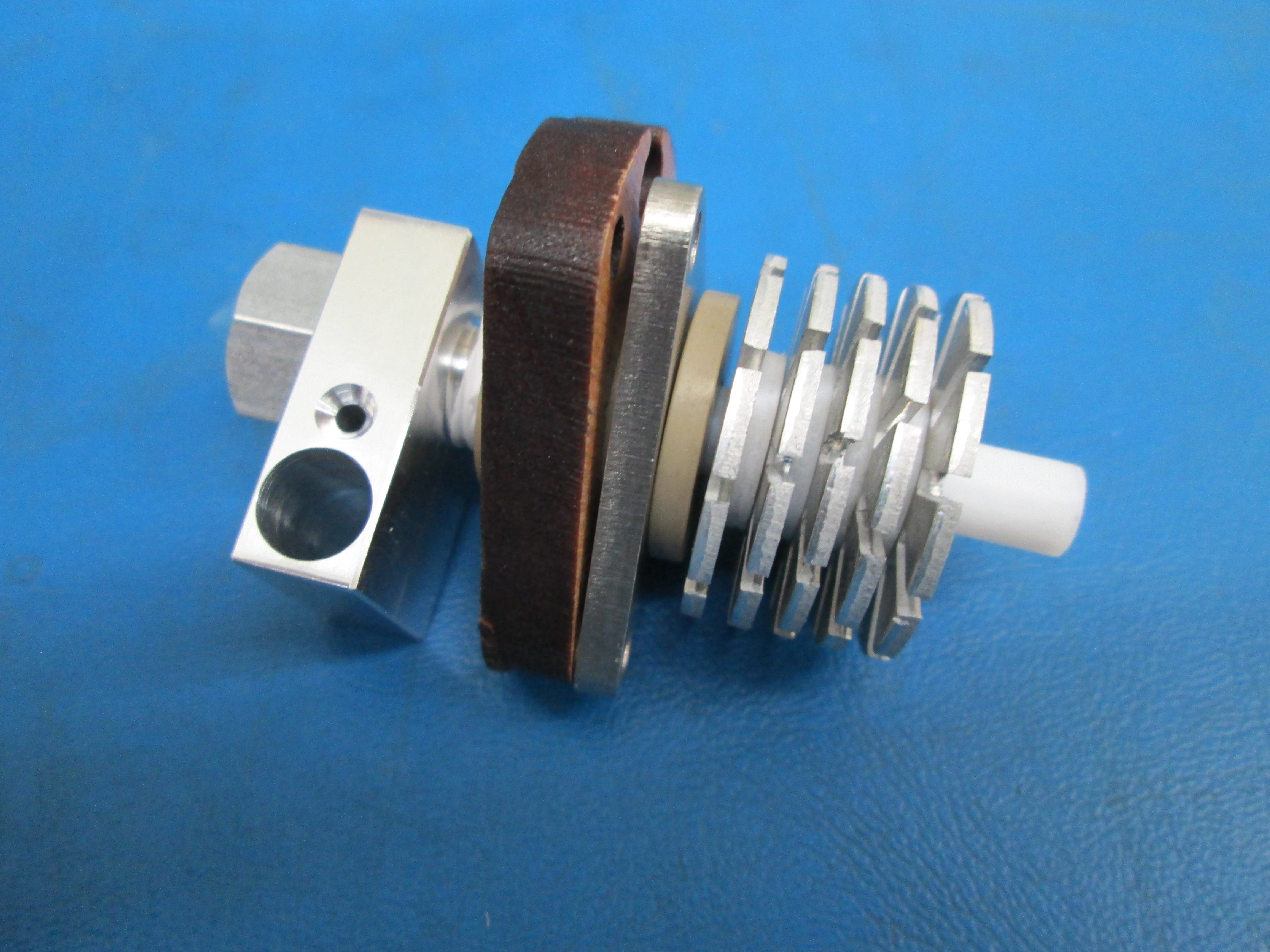
Slide heat sink washer down the PTFE tube till its flush with the peek isolator
Slide low friction PTFE washer down the PTFE tube till its flush with the heat sink washer
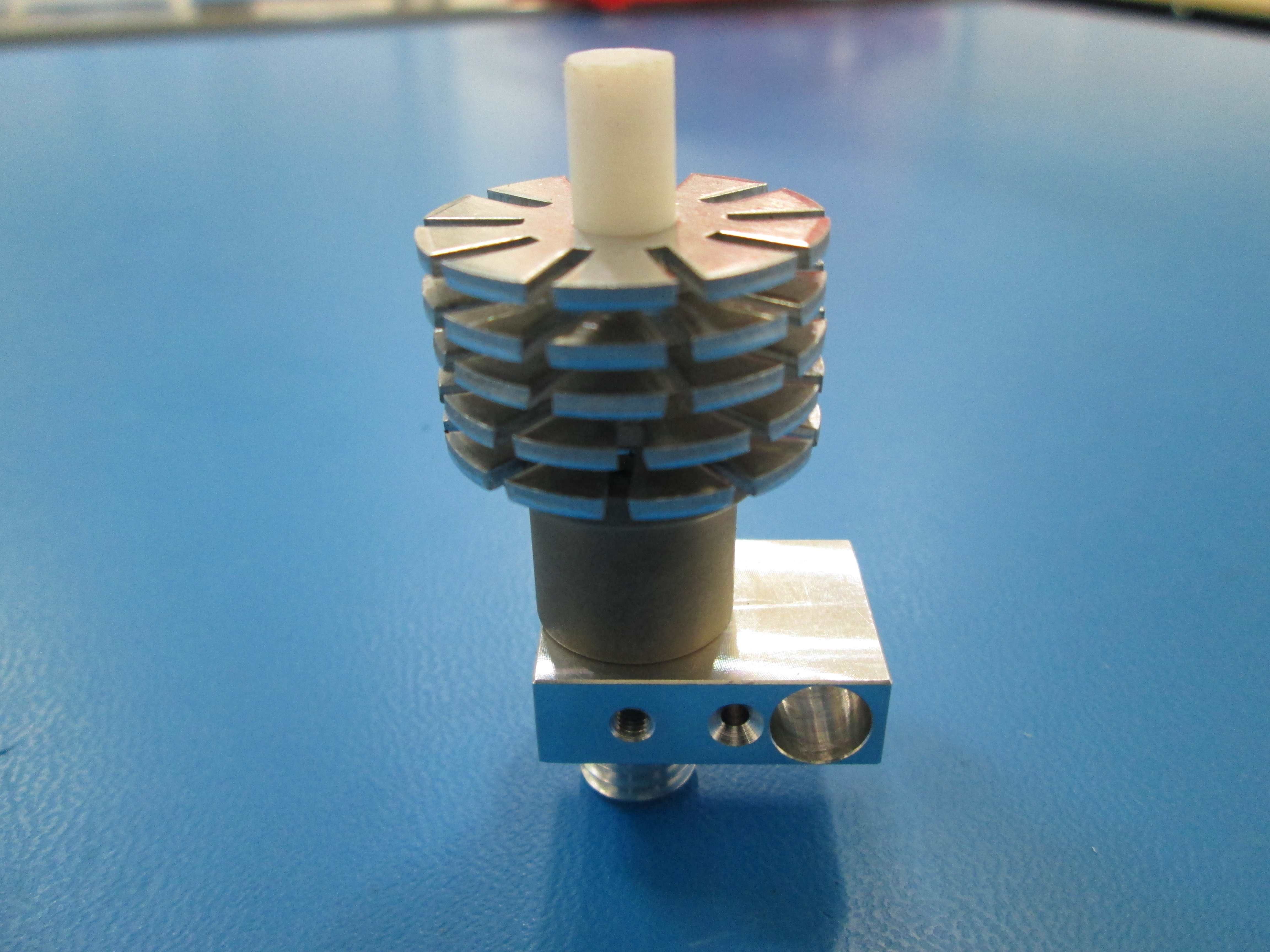
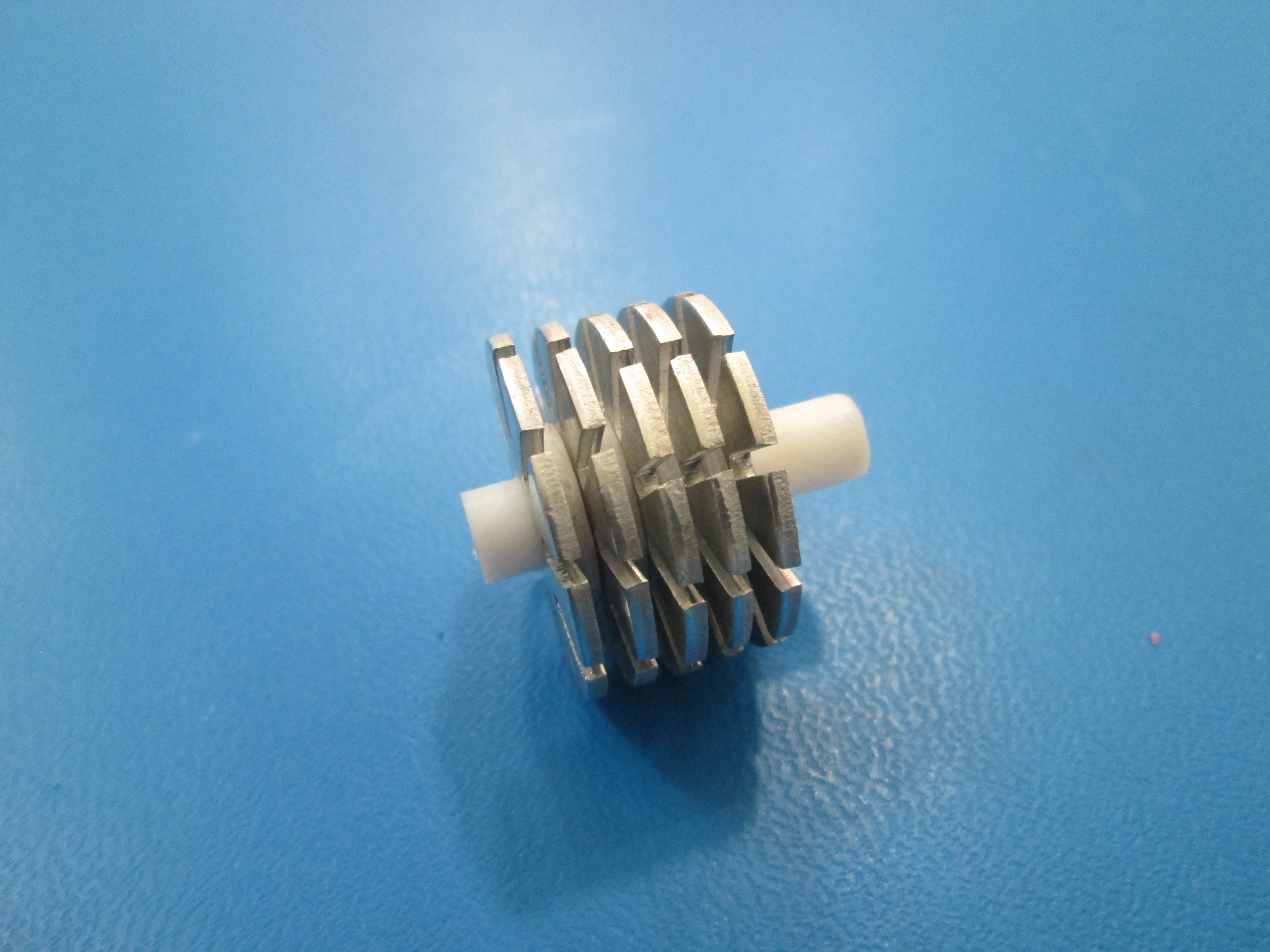
Continue this until there are 5 heat sink washers and 4 PTFE washers stacked on top of each other as shown
Once this is complete, you can remove the heat sink from the peek isolator
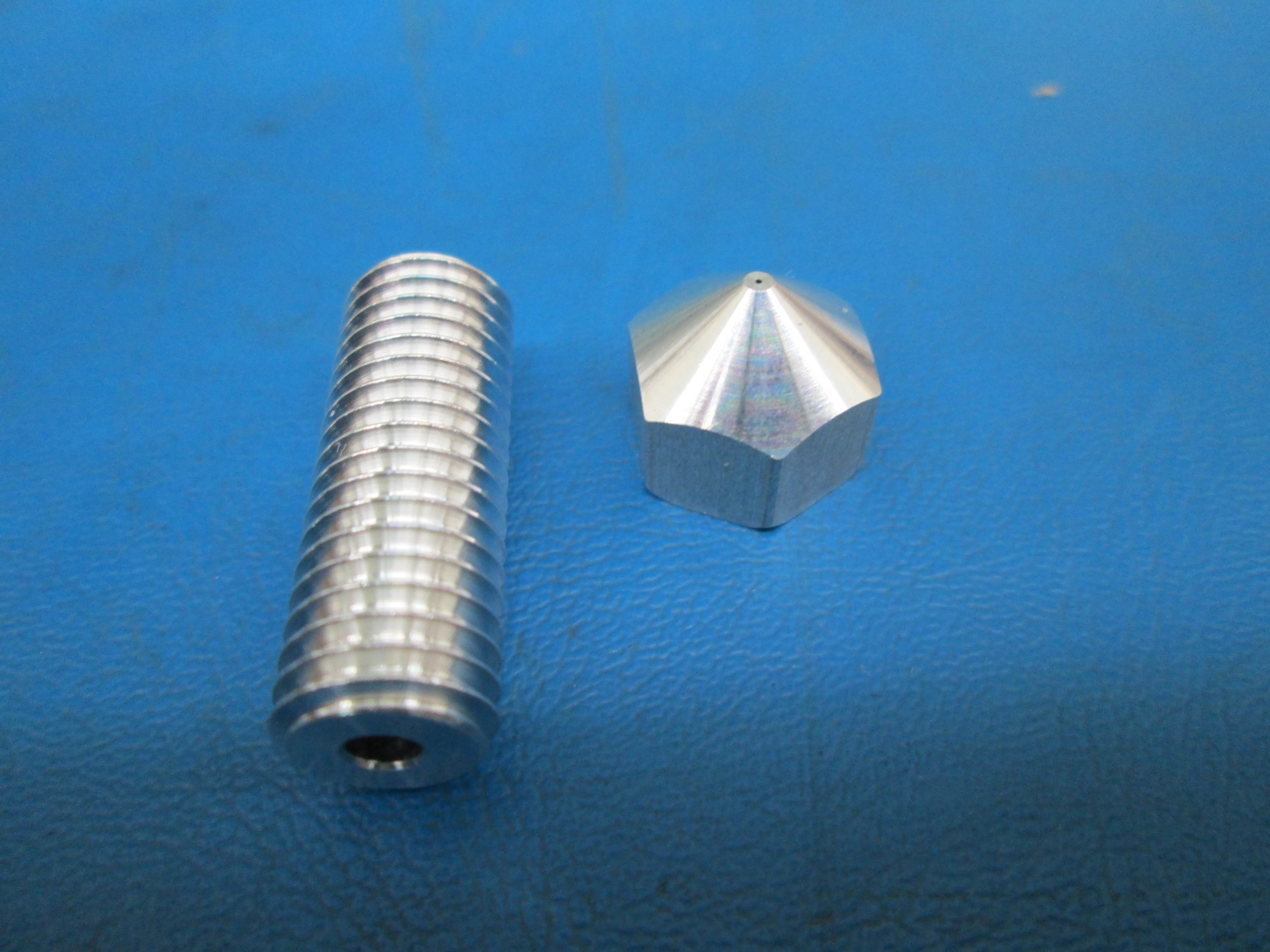
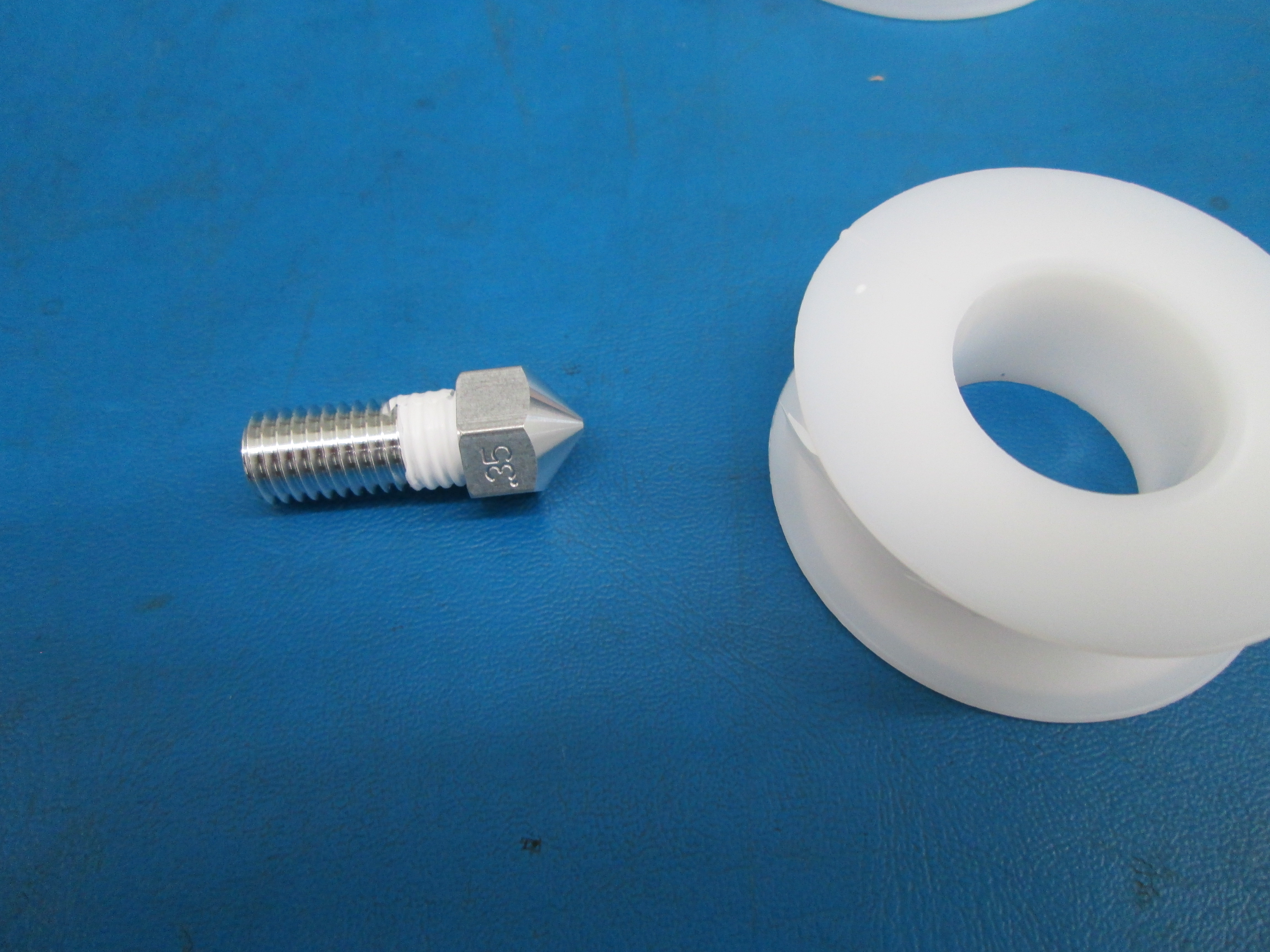
Screw nozzle onto threaded extension, it just has to be finger tight
Take ~40mm piece of Teflon tape and wrap it around the threaded extension, flush with the nozzle, clockwise, while holding it vertical with the nozzle at the bottom
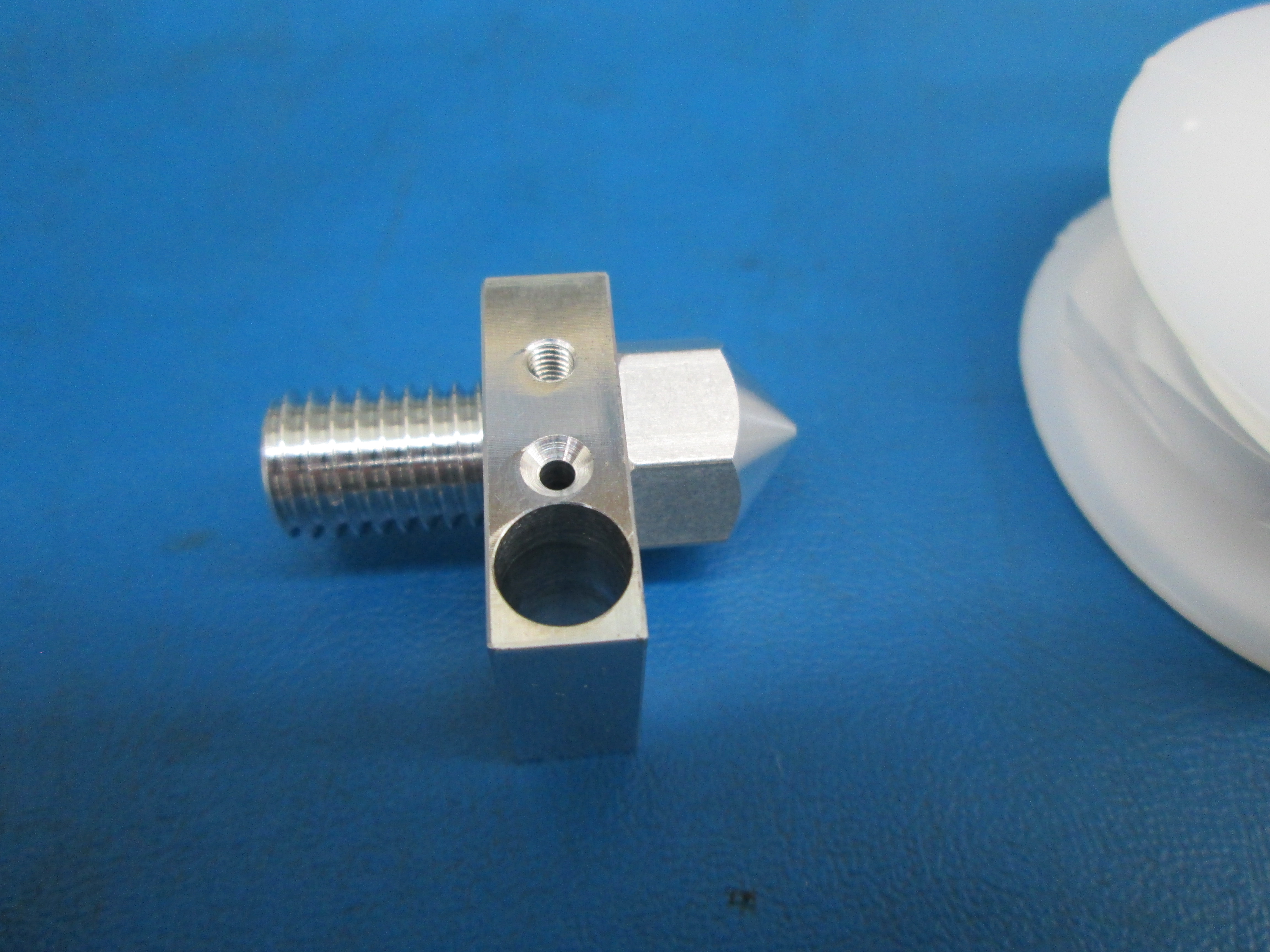
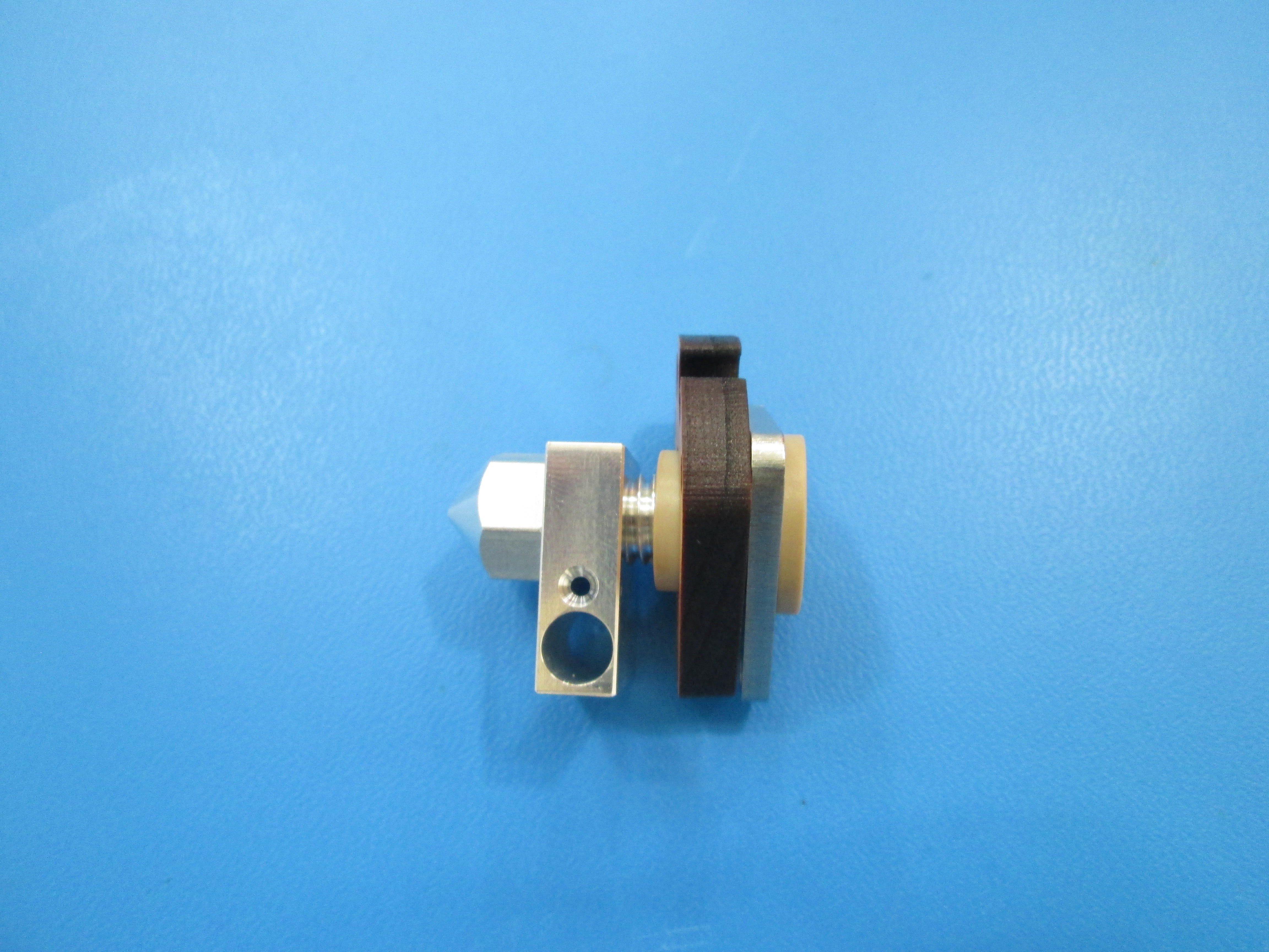
Screw heater block down over the Teflon tape and flush with the nozzle
Hold the heater block with your fingers and lightly tighten the nozzle with the 13mm wrench
Take another piece of ~40mm Teflon tape and wrap it clockwise around the top of the threaded extension

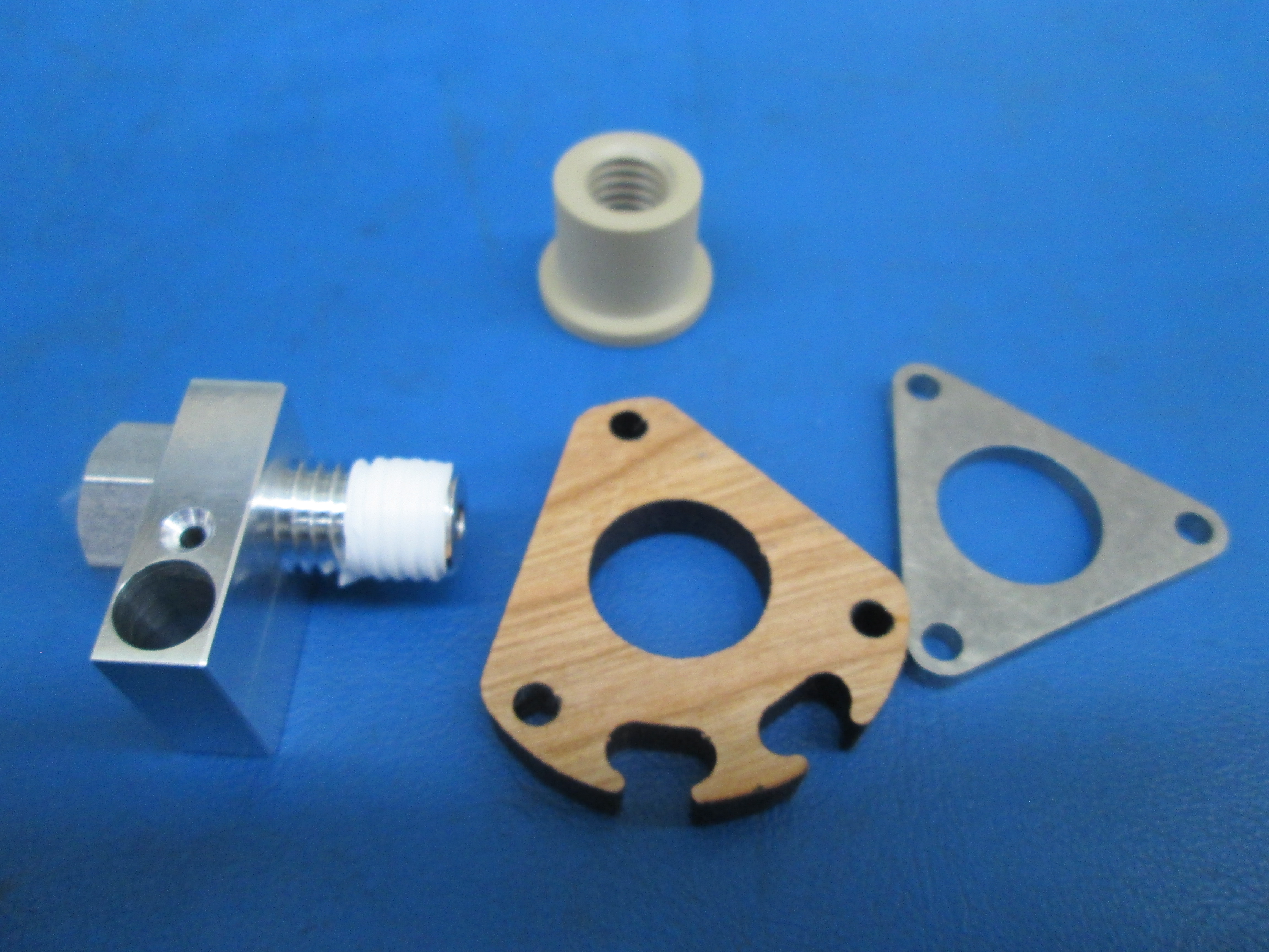
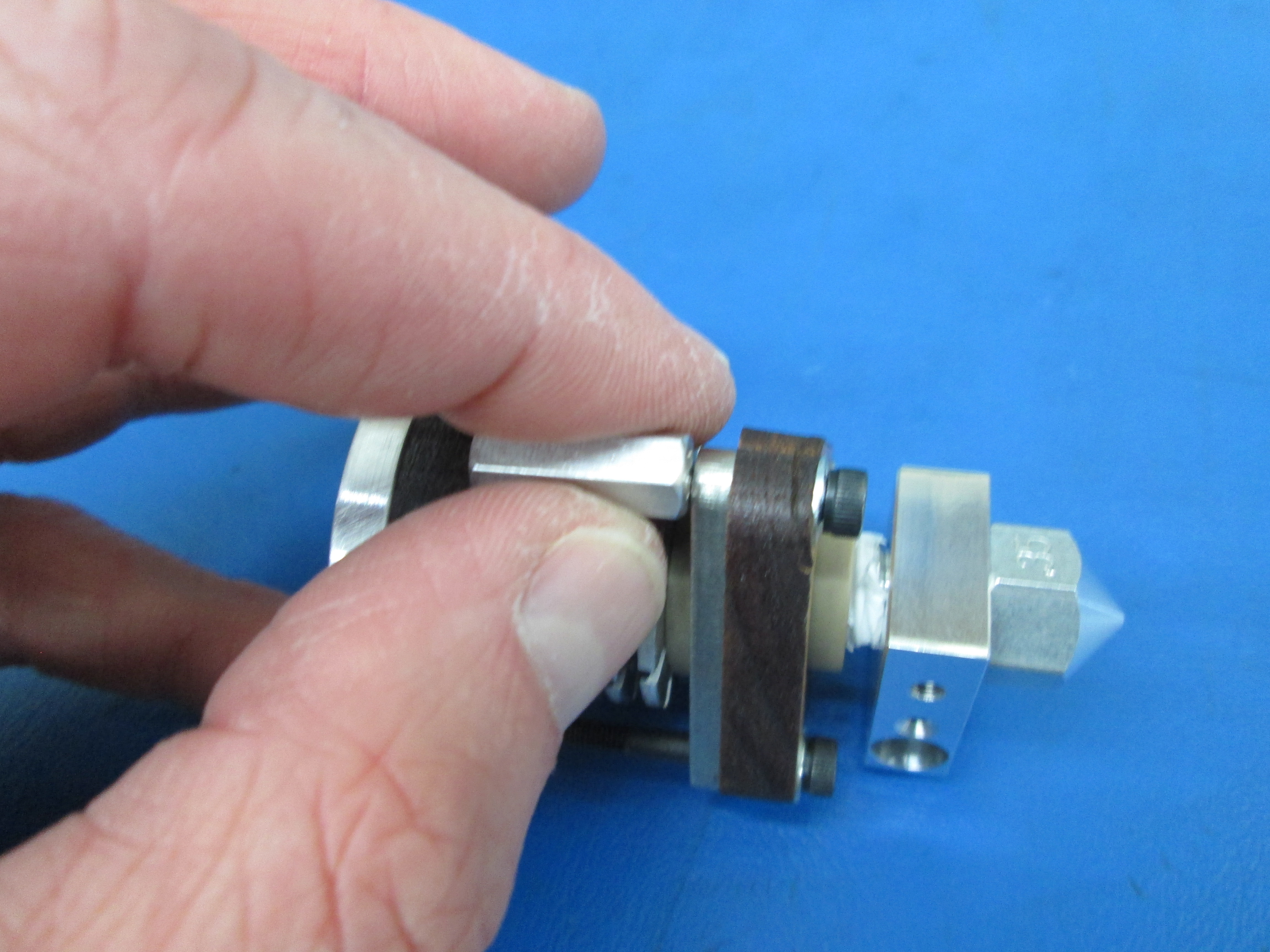
Place the 2.0 lower plate(triangular wood piece) and 1.1 backup plate(triangular metal piece) onto the threaded extension
Screw the peek isolator onto the threaded extension till its flush with the threaded extension, making sure you don't pinch the lower plate in between the peek insolator and the heater block
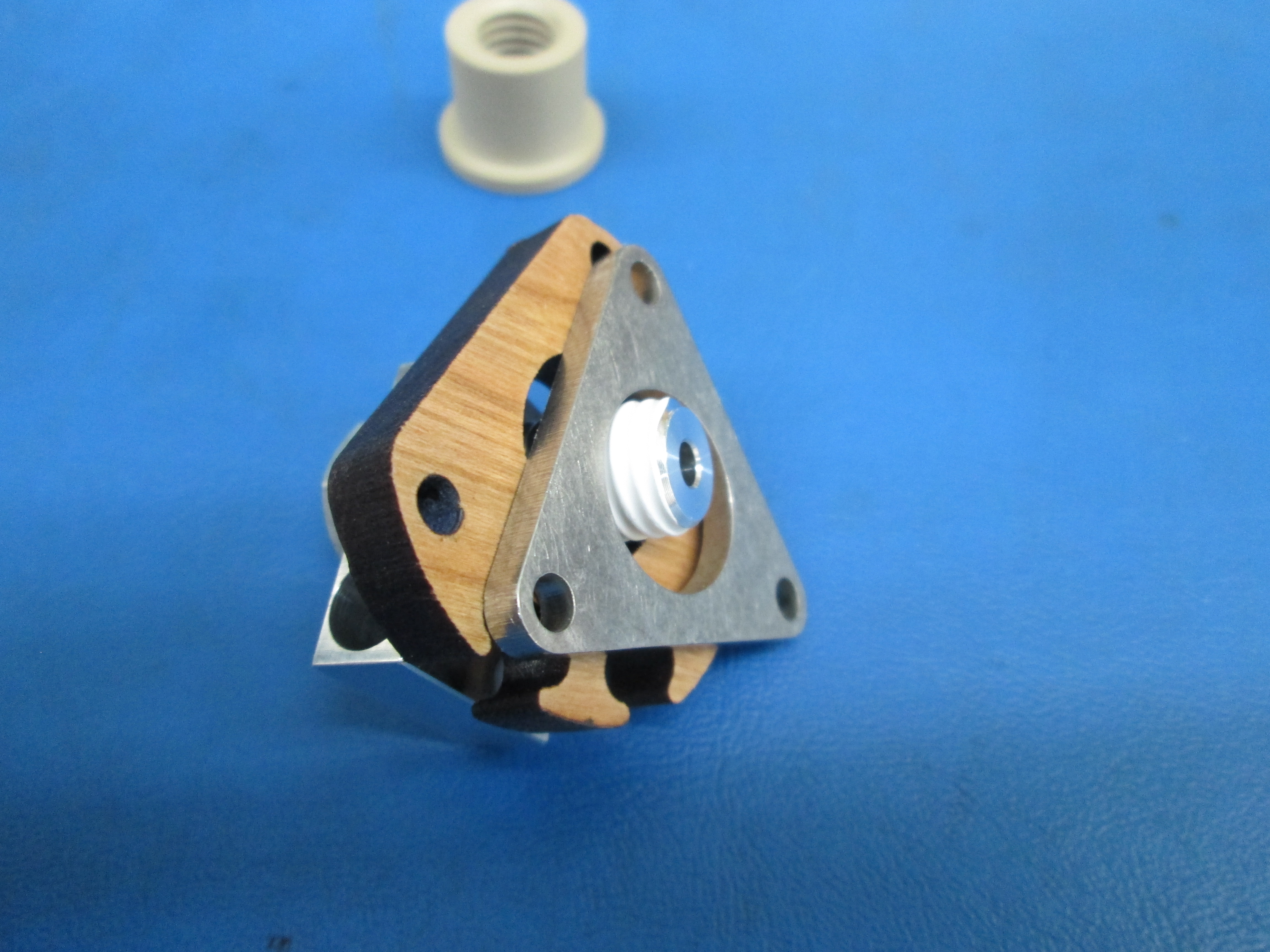
Insert the heat sink into the peek isolator, making sure the shorter side of the PTFE tube is inserted into the peek isolator
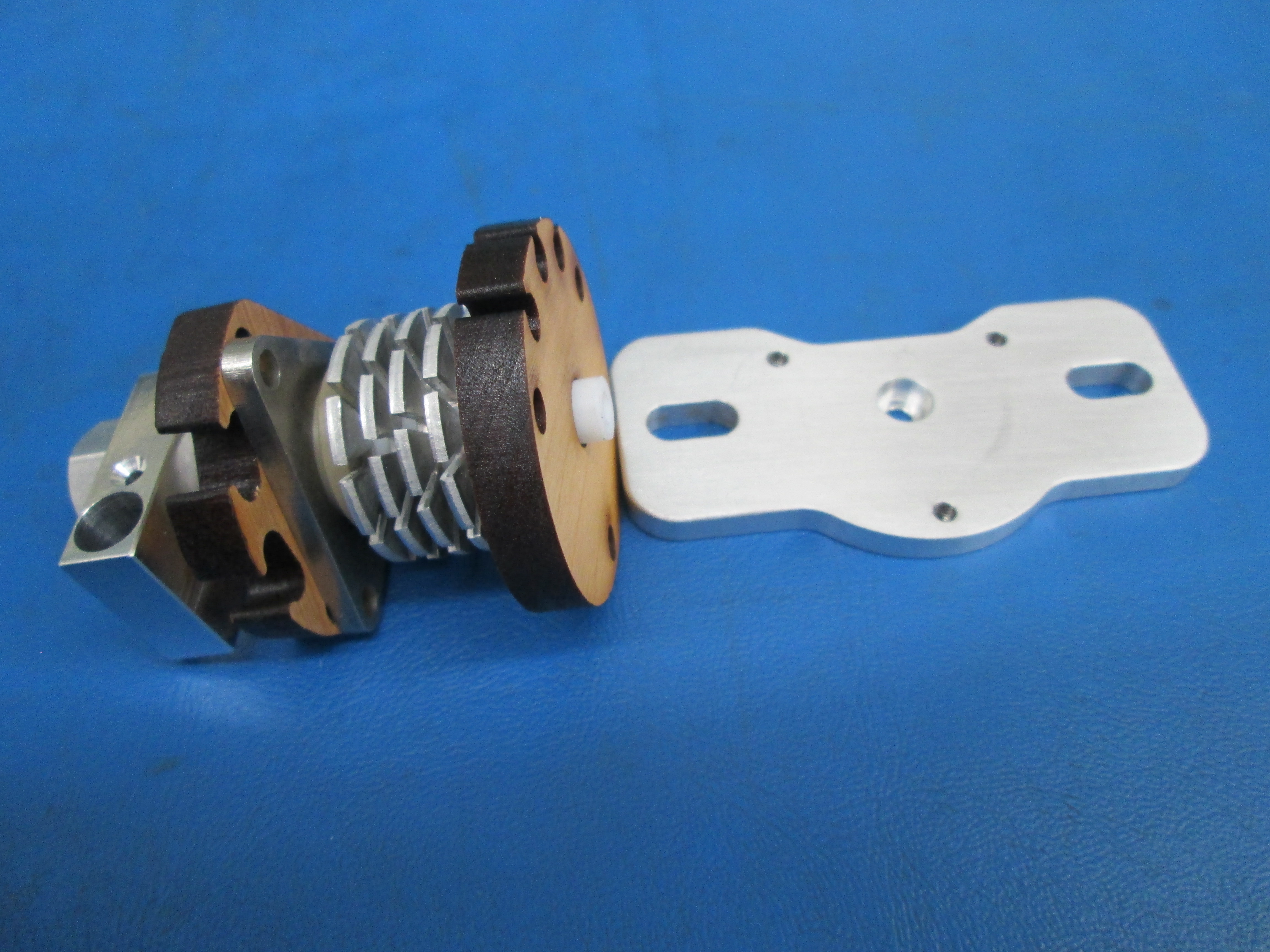
Slide the 2.0 upper plate over the PTFE tube
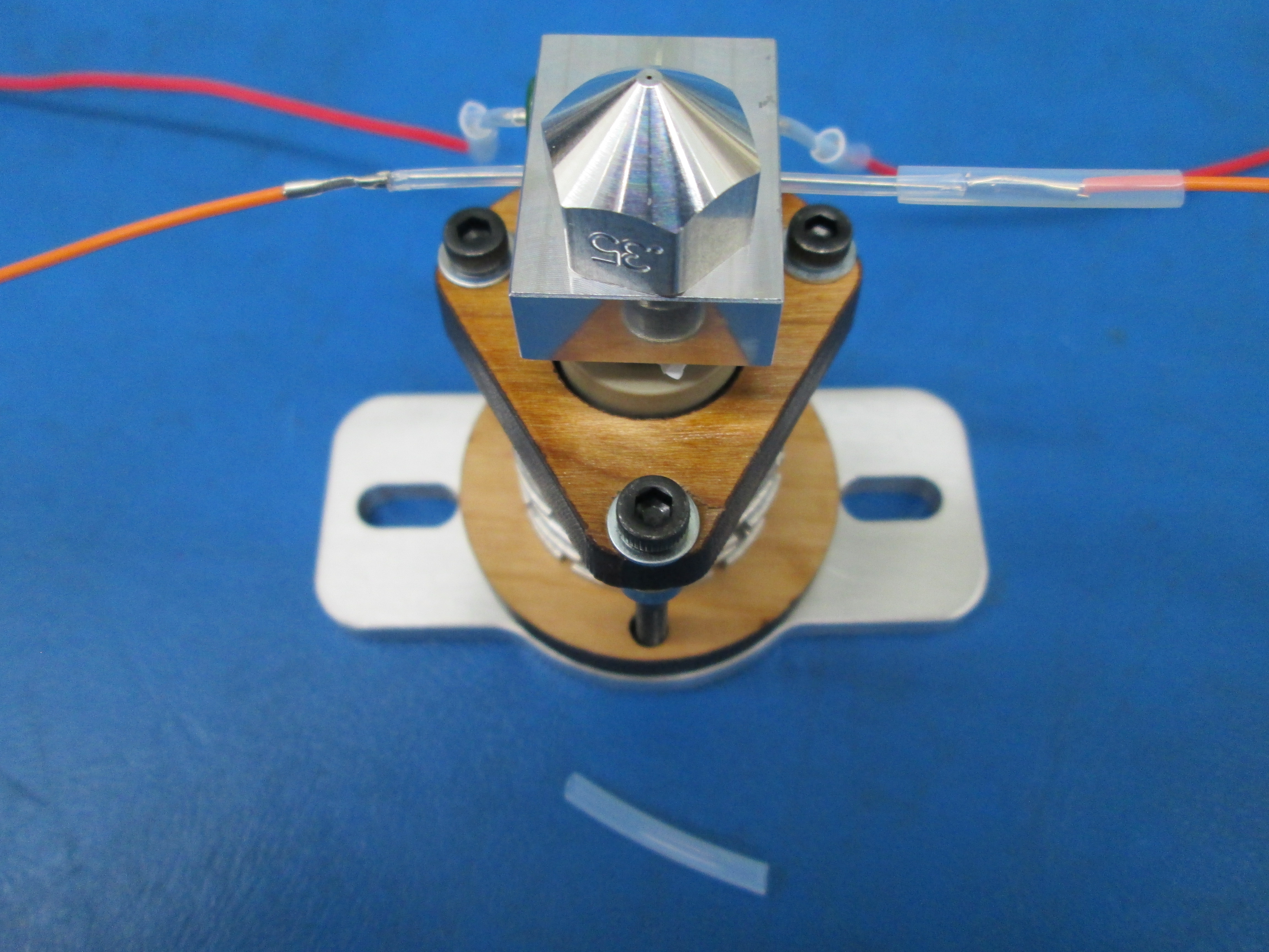
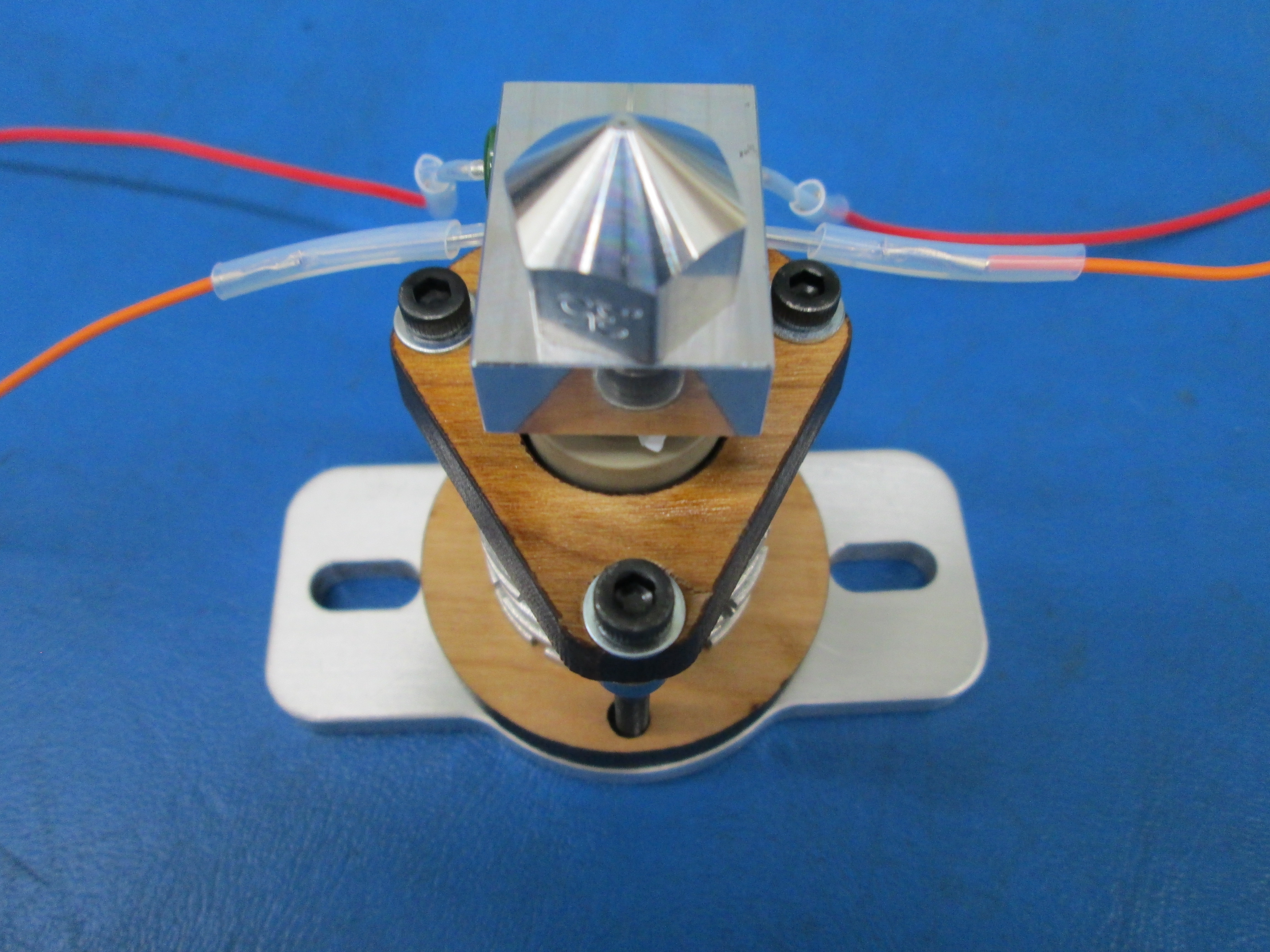
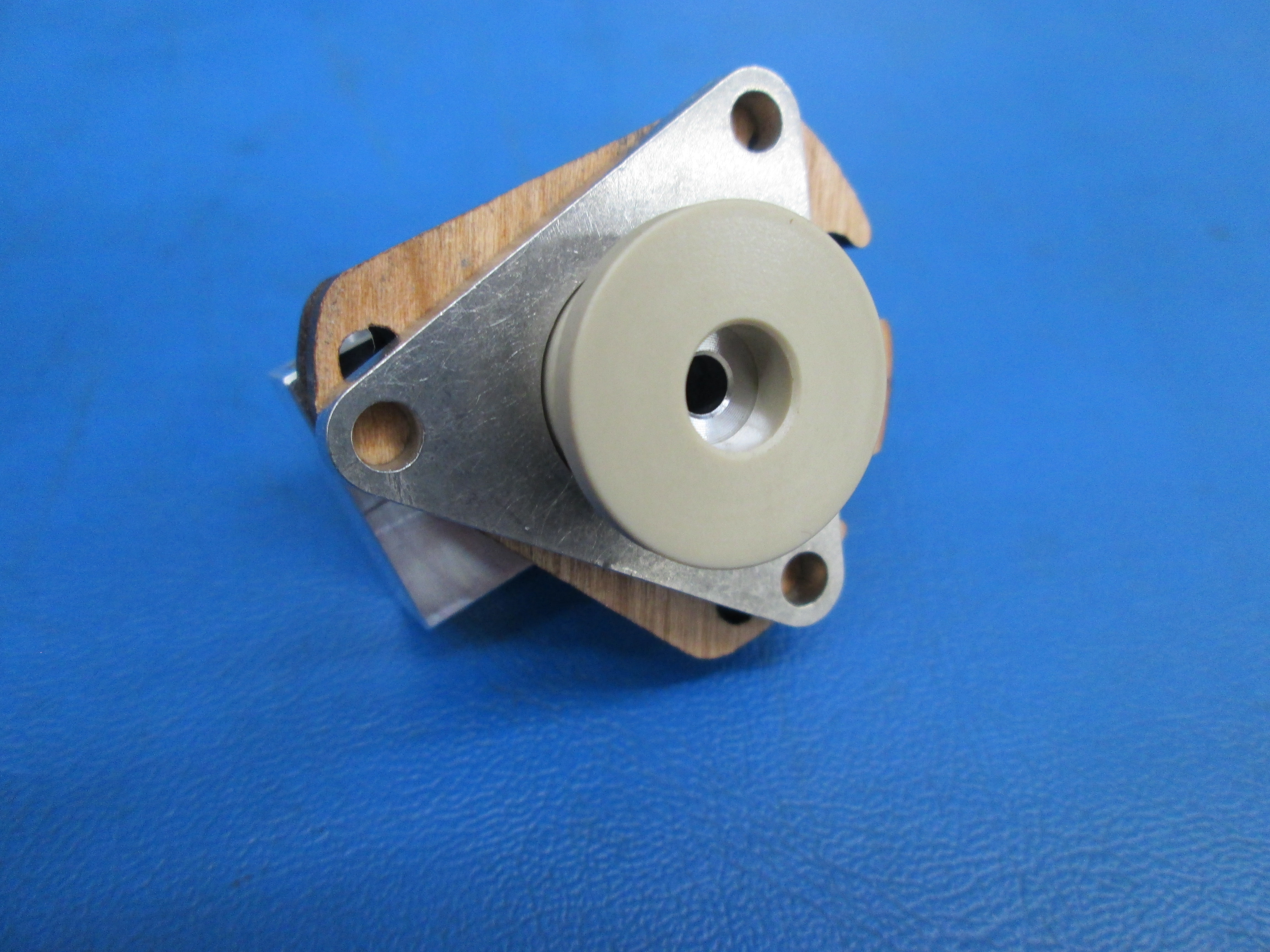
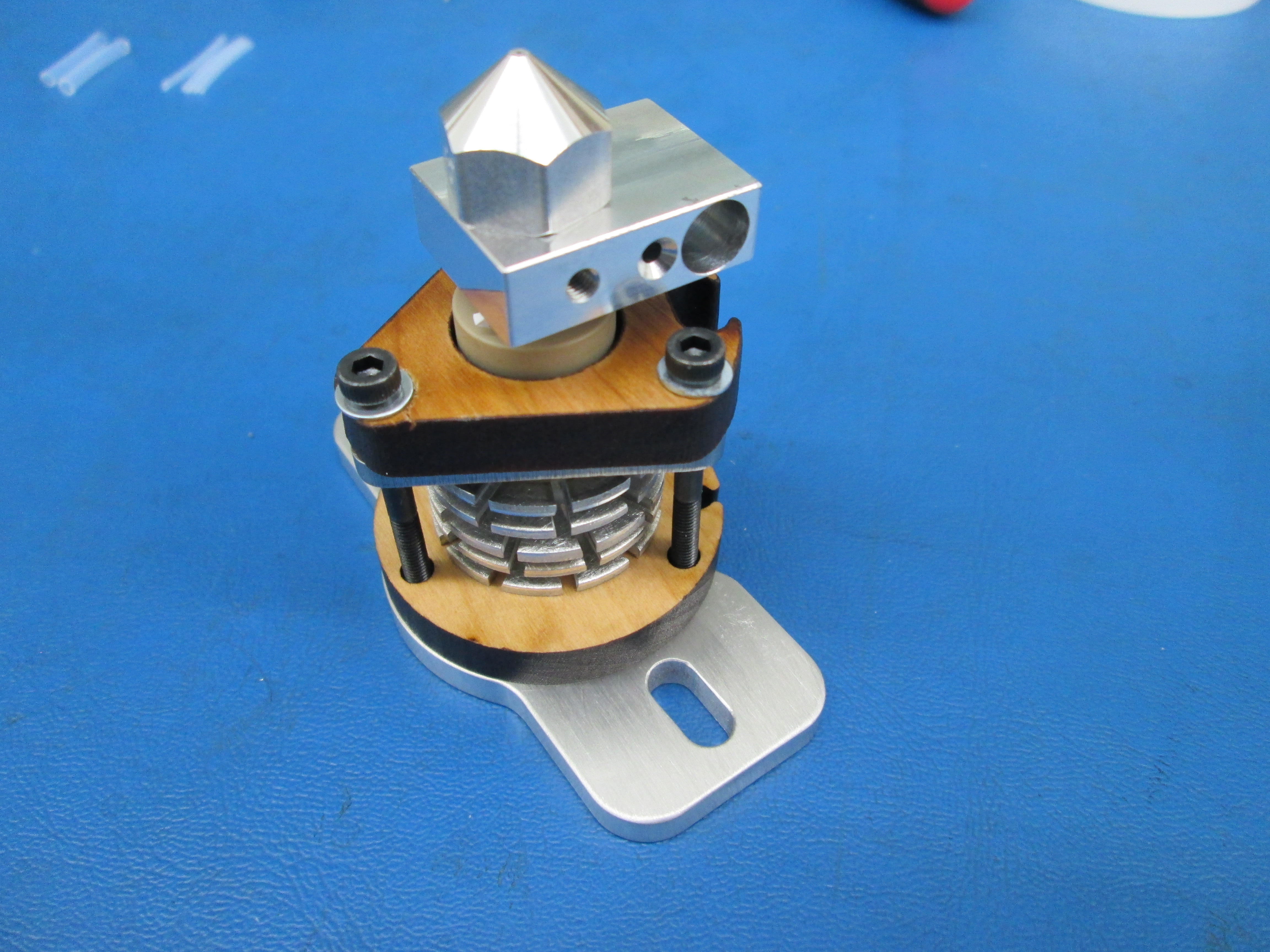
Now set the assembly into the counter bore of the mount plate
Line up all the bolt holes for the 3 M3x35 SHCS, making sure that the heater block is oriented correctly as shown
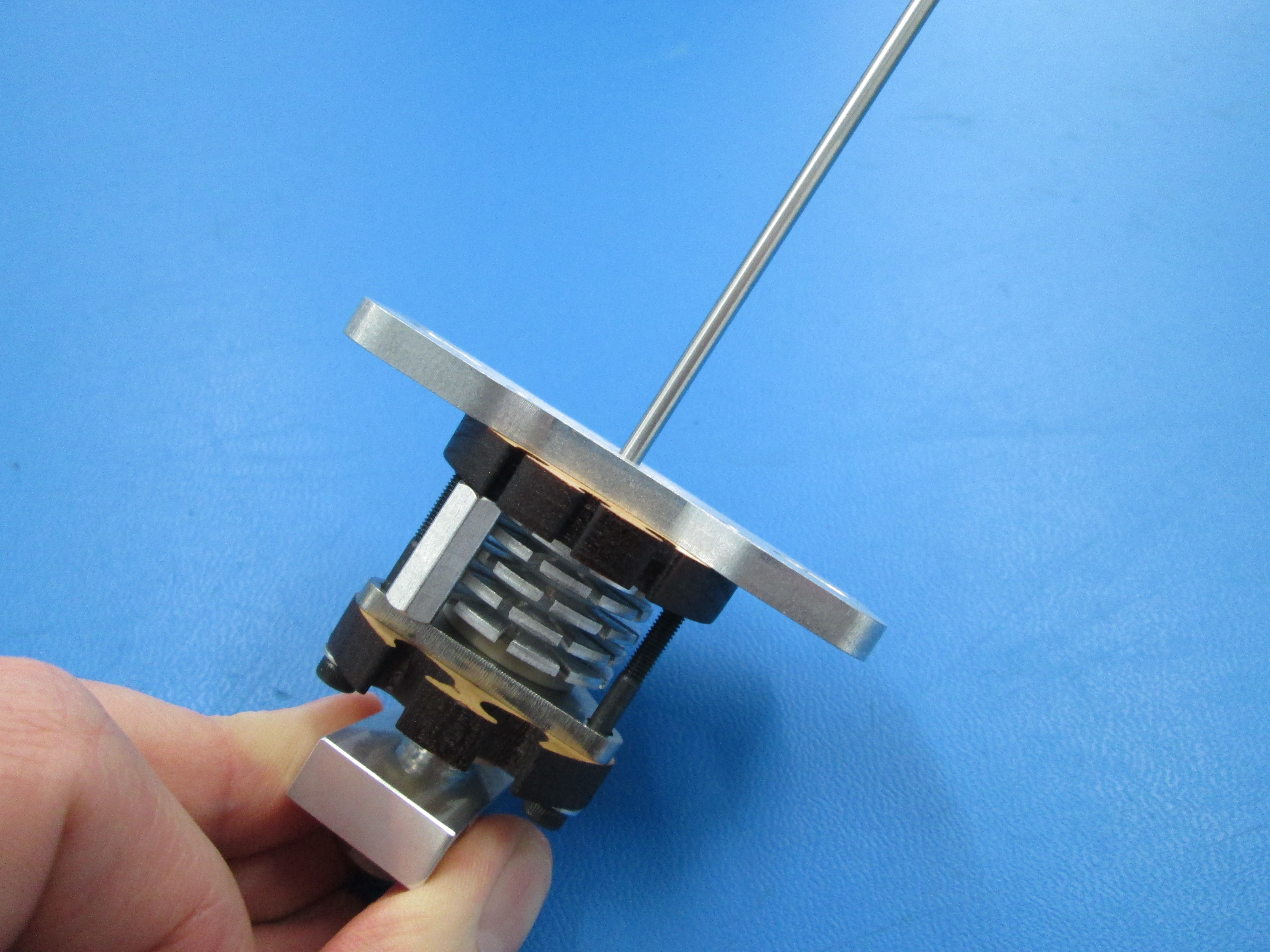
Insert alignment rod before you tighten the bolts
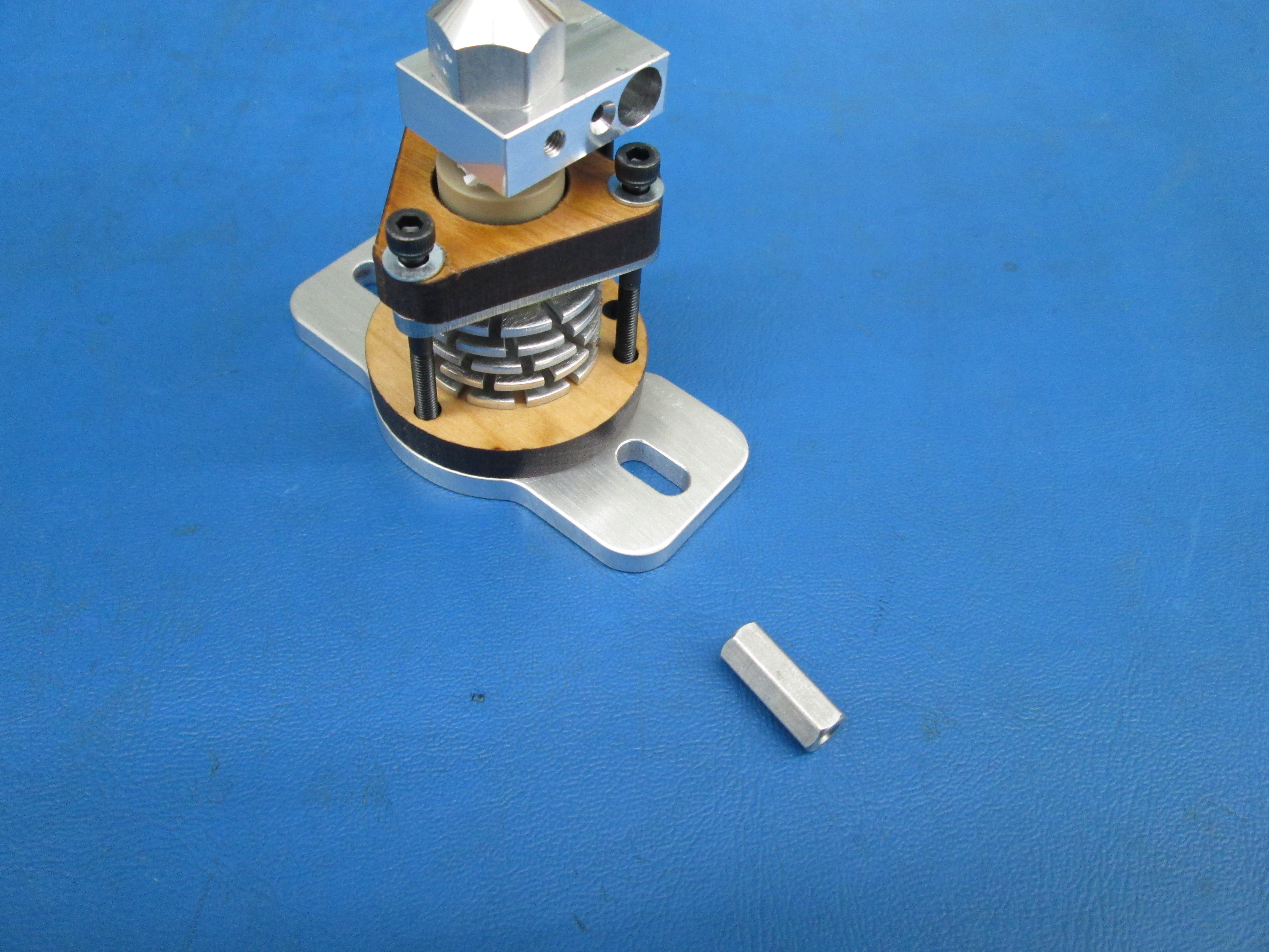
Tighten the 3 M3x35 SHCS with washers slowly, in an alternating pattern to insure evenness
Use the spacer to check the gap between the upper plate and the backup plate
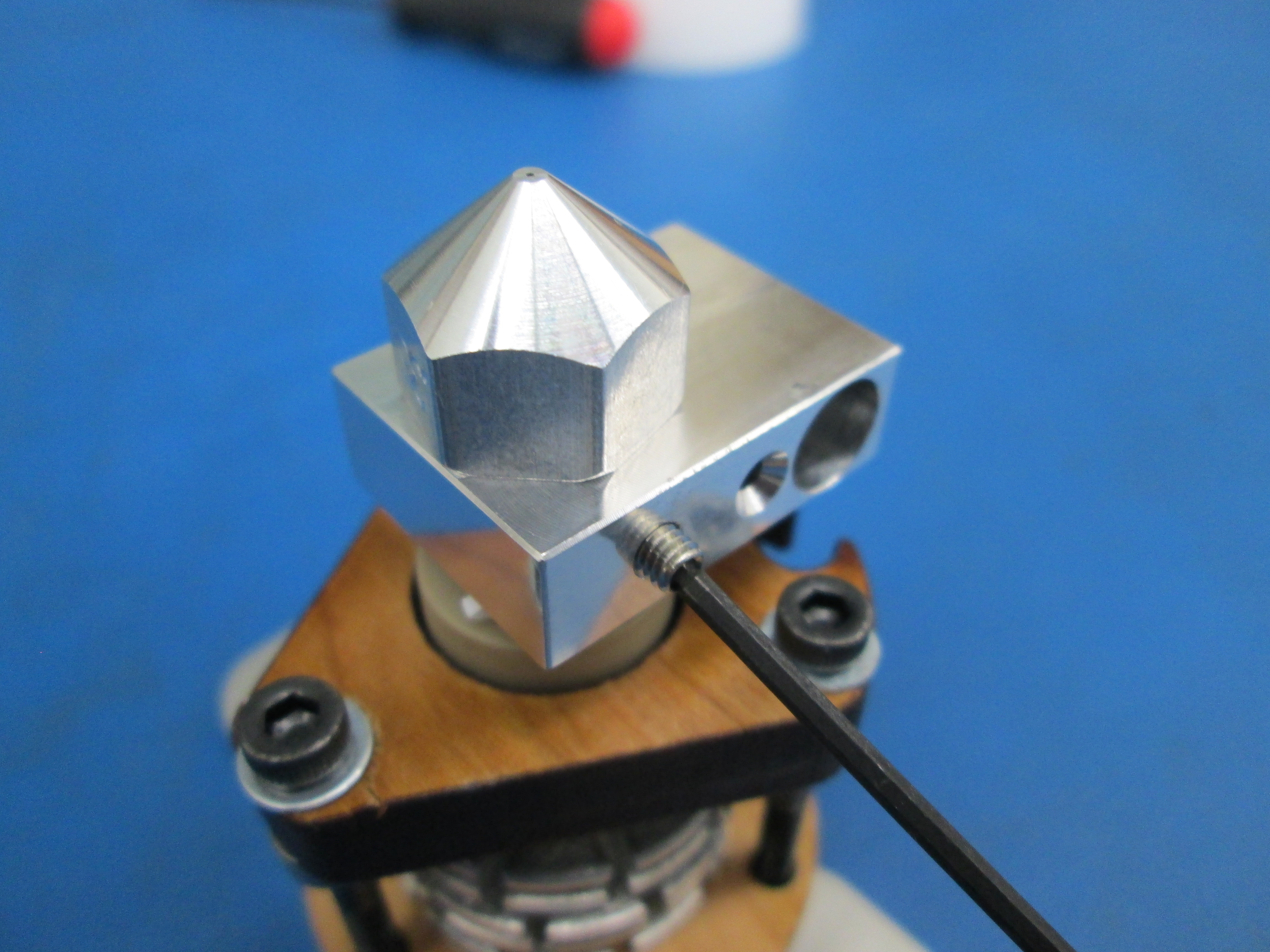
Now insert the M3x4 set screw into the heater block
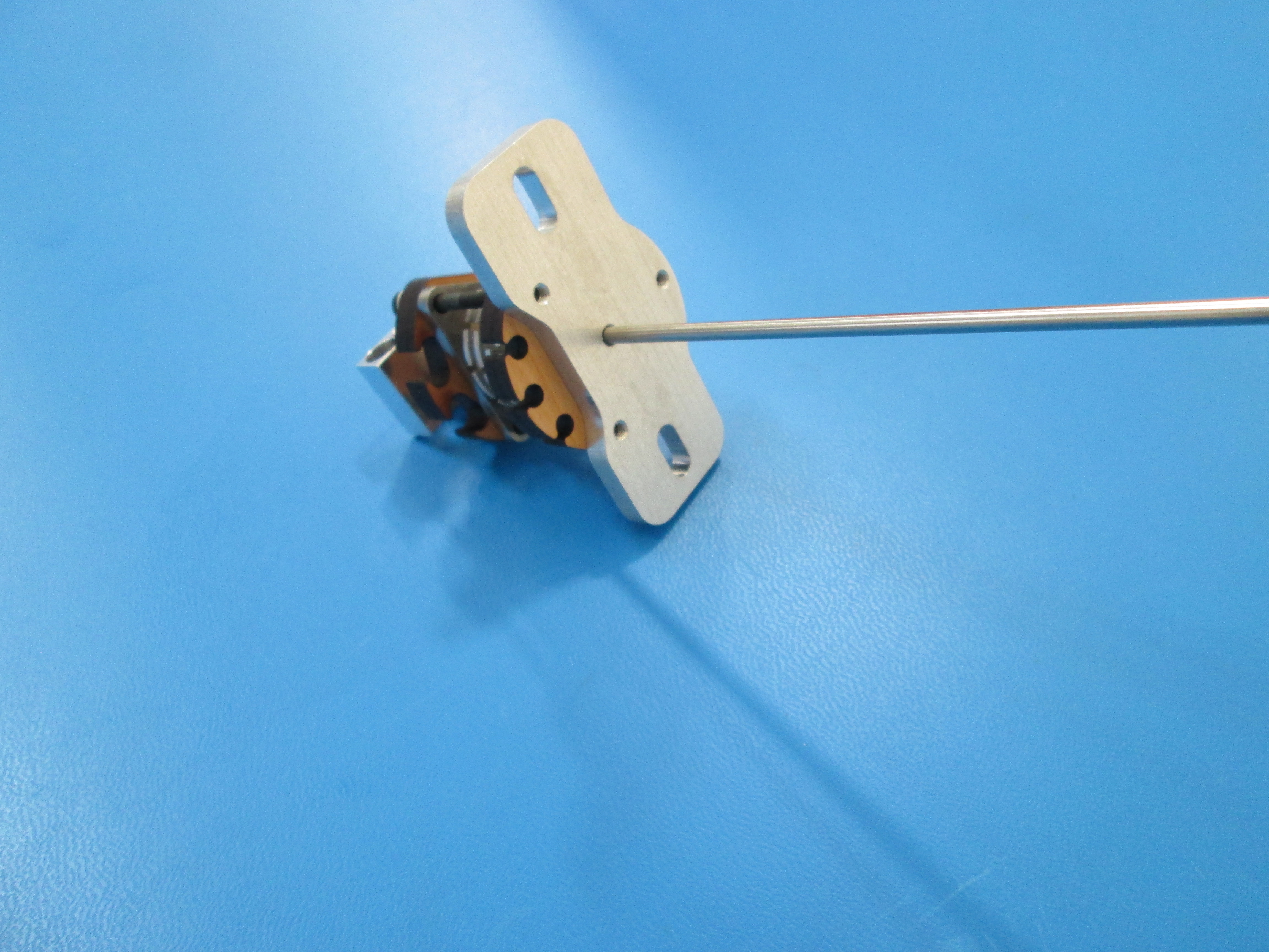
Use metal rod and check alignment, making sure it slides in and out smoothly
Mark bottom of lower plate with batch letter


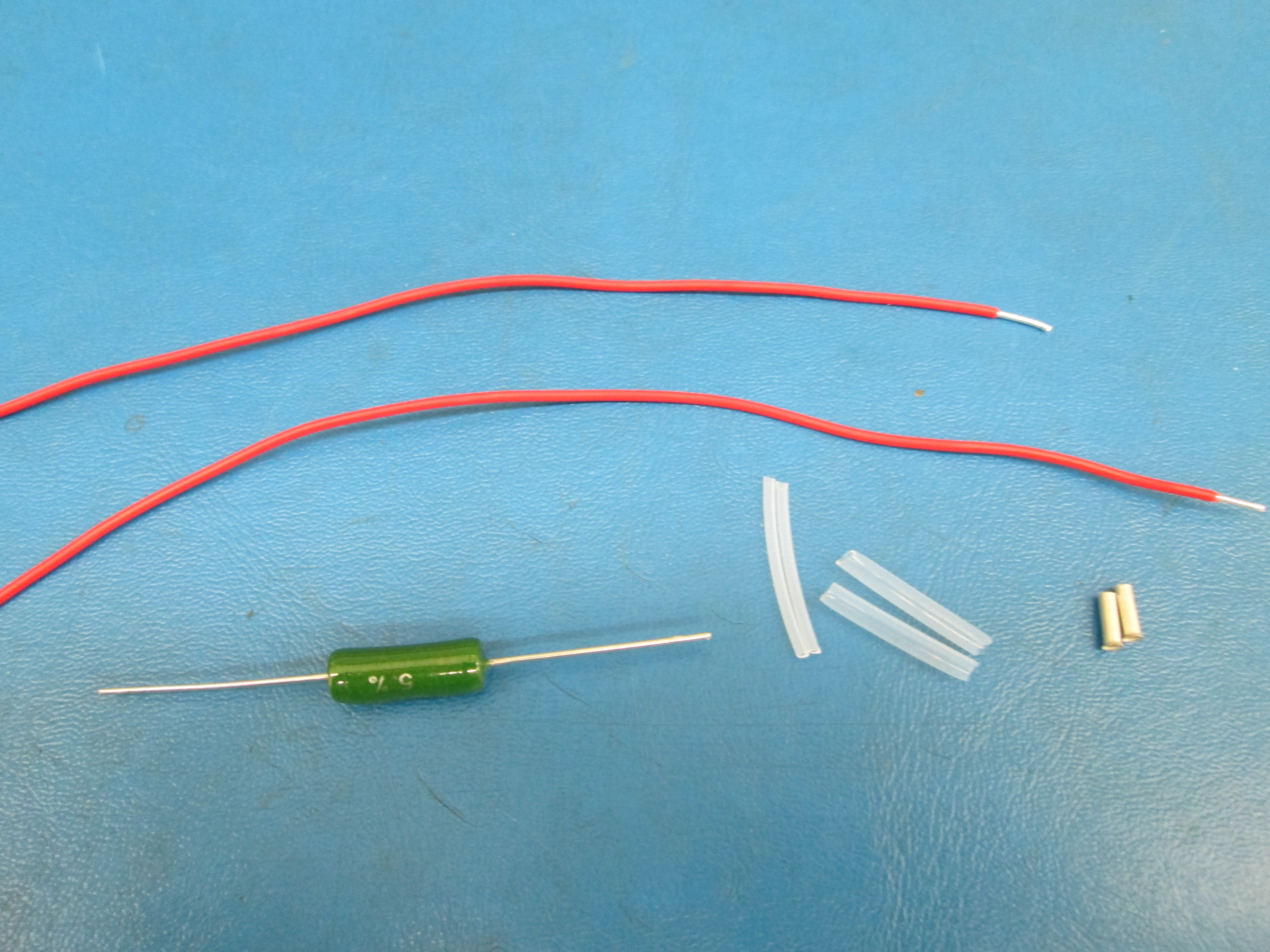
First strip two red 20 AWG wire on both ends about 5mm
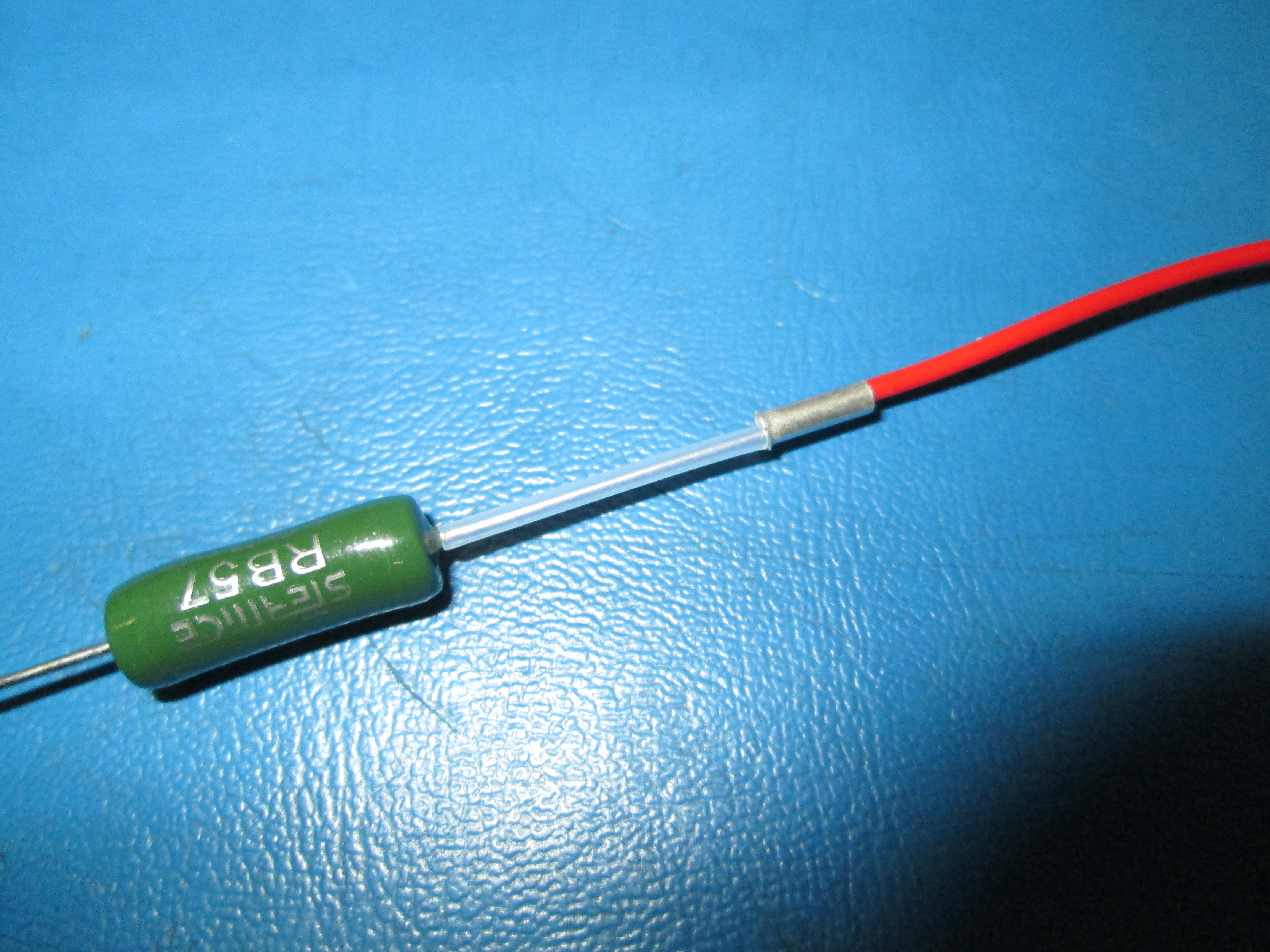
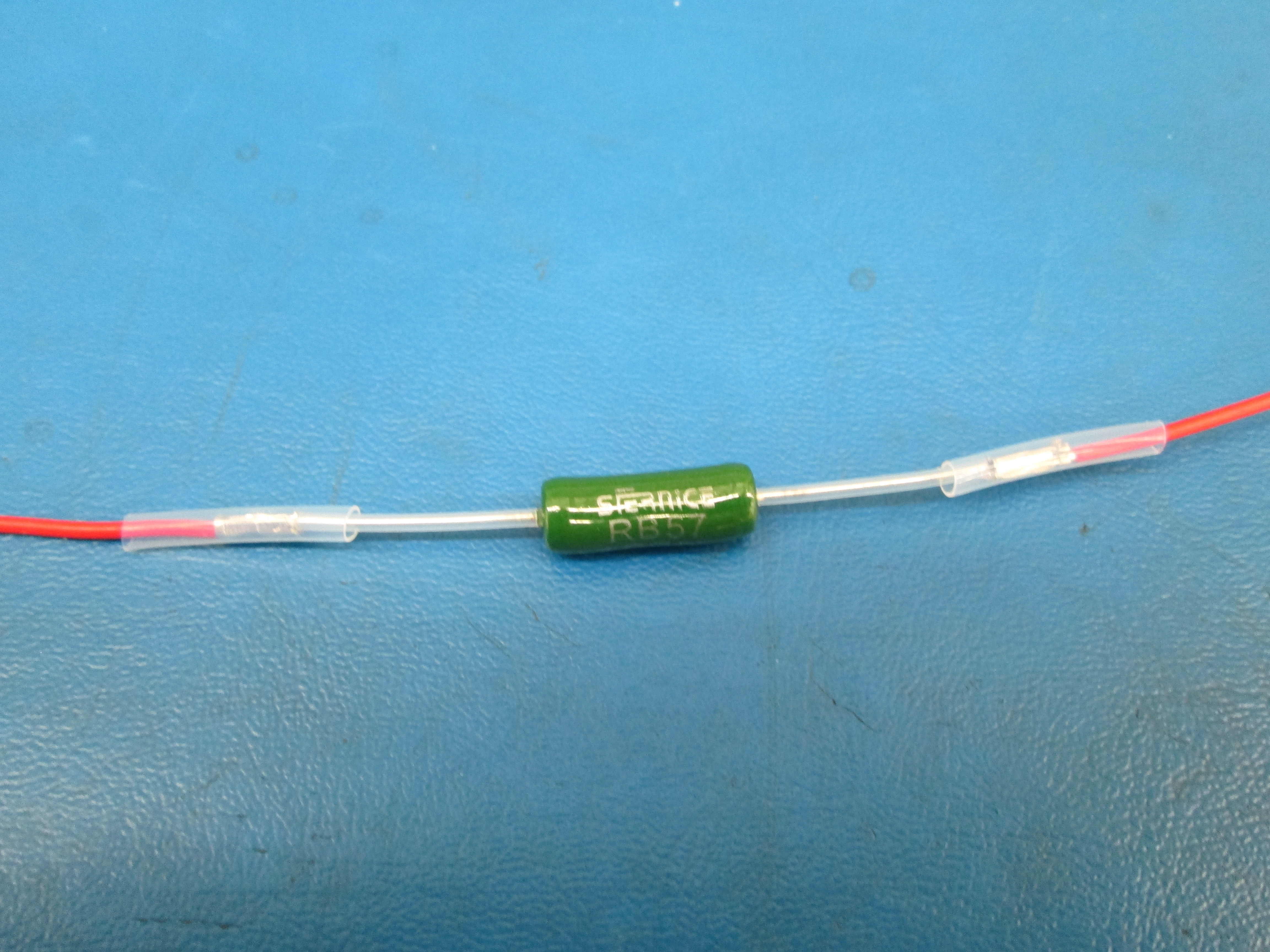
Take the 4.7 Ohm resistor and slide a piece of the 20 AWG PTFE insulation over it then take a 16 AWG ferrule and slide it flush with the PTFE insulation, you might have to hold it in place with your finger
Slide the striped end of the red wire into the ferrule, the insulation of the wire should be flush with the ferrule
Crimp the ferrule with the wire crimper making sure that the wire or the resistor doesn't slide out
Pull the wire and resistor to make sure that they are secured within the ferrule and make sure the two are making contact within the ferrule
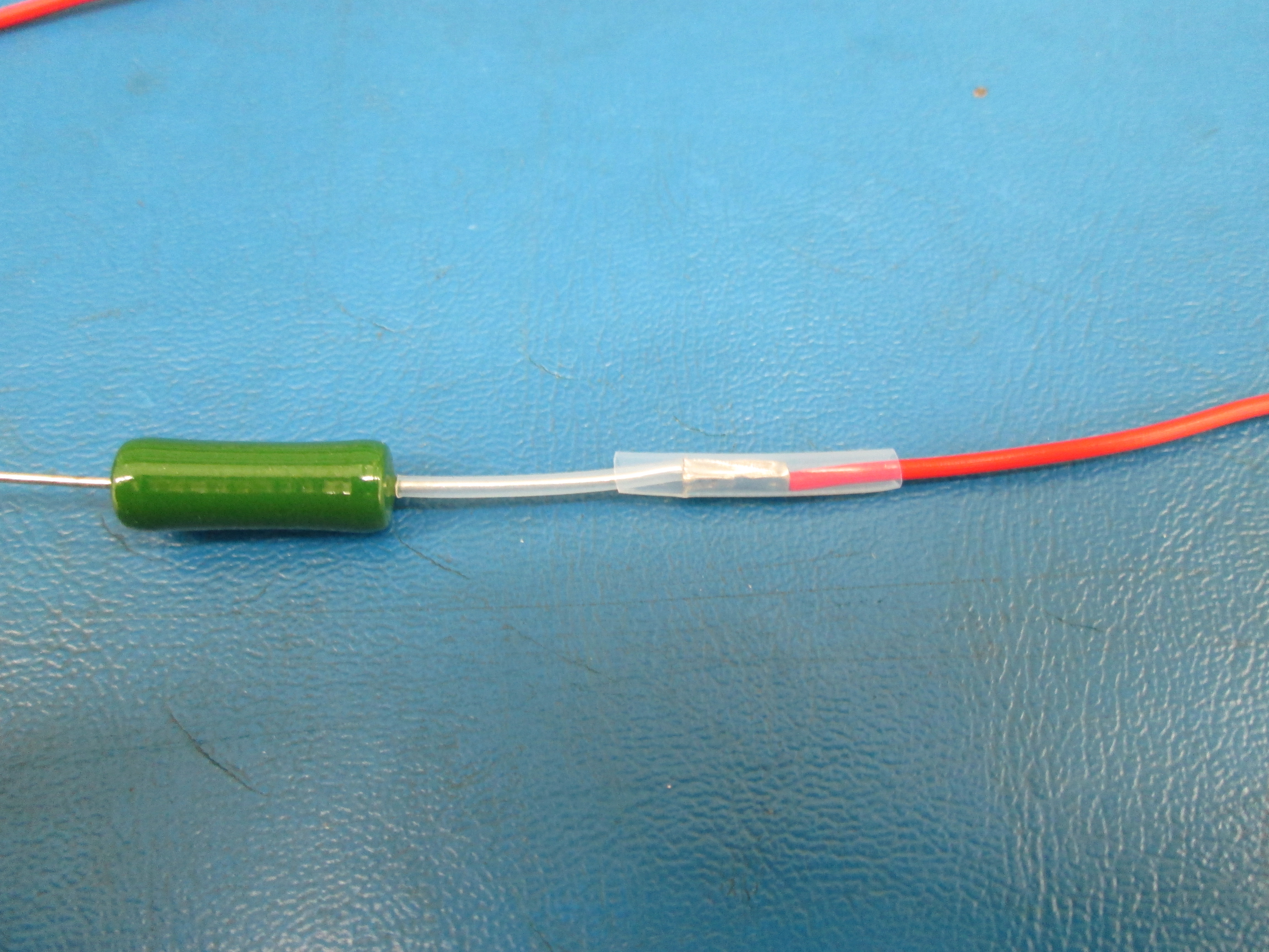
Slide a piece of the 11 AWG PTFE insulation over the ferrule making sure the insulation is centered over the ferrule
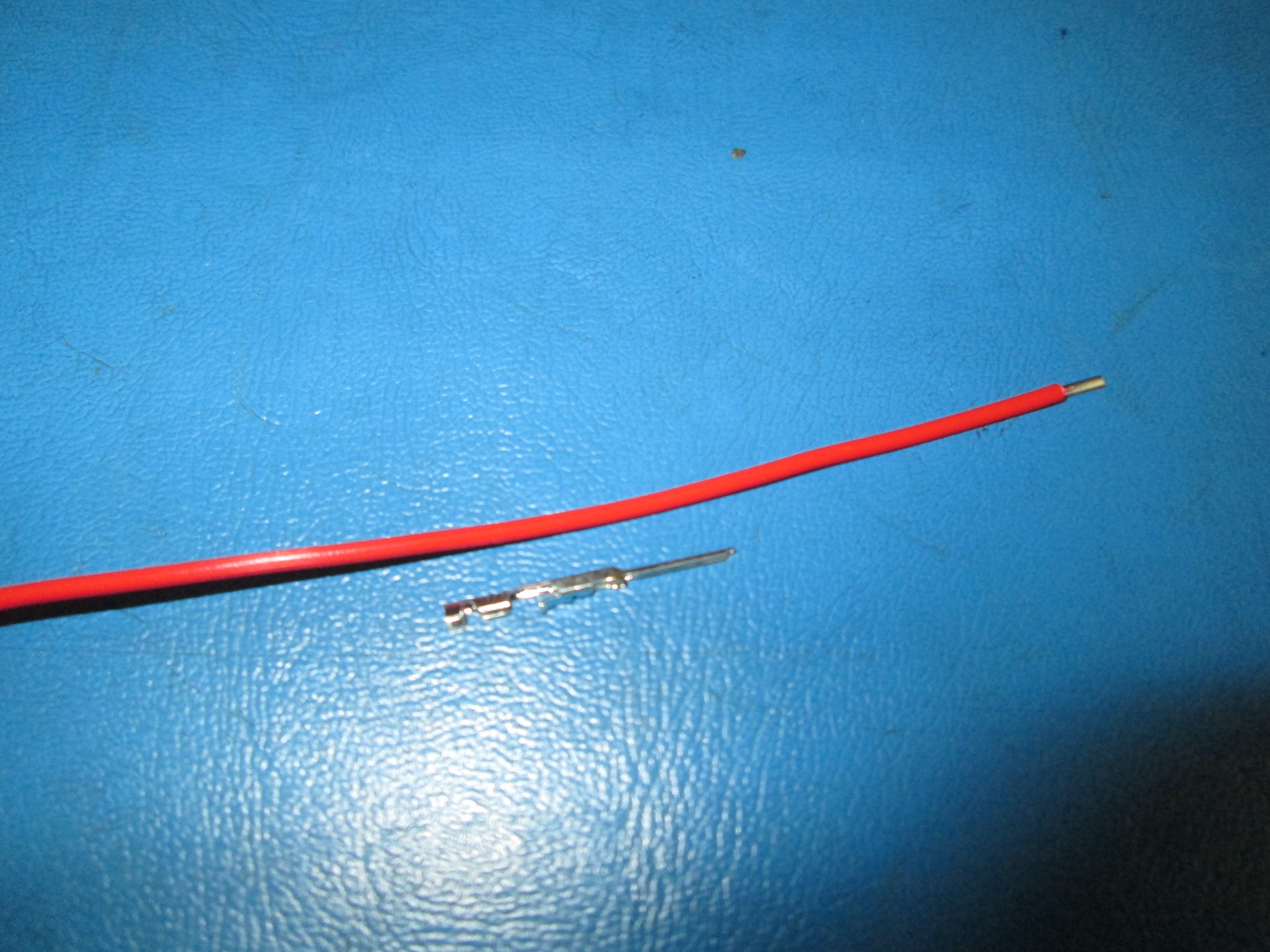
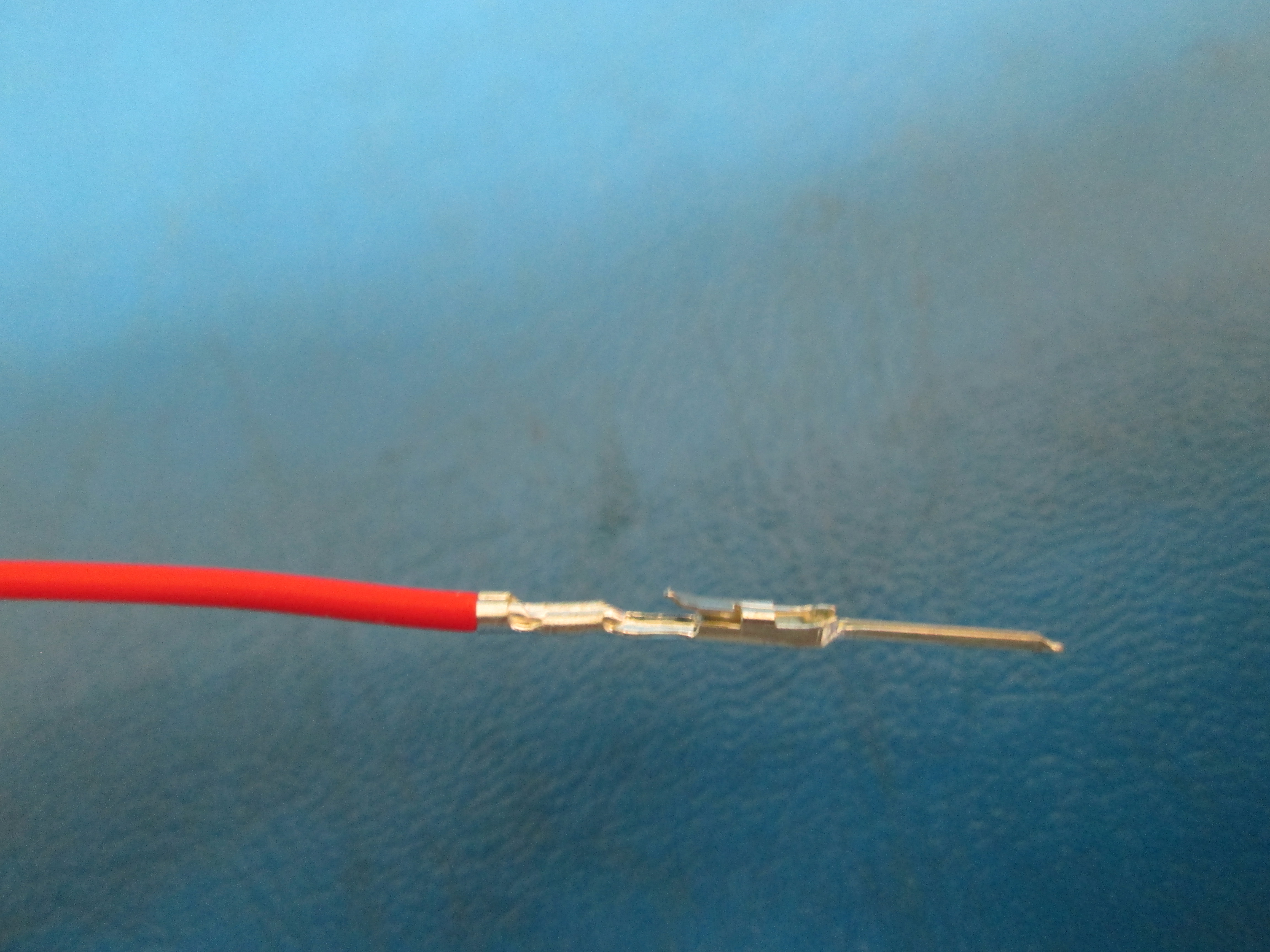
Crimp a male terminal connector to the other end of the red wire that is striped making sure that it is secure with proper contact
Repeat this on the opposite side of the resistor

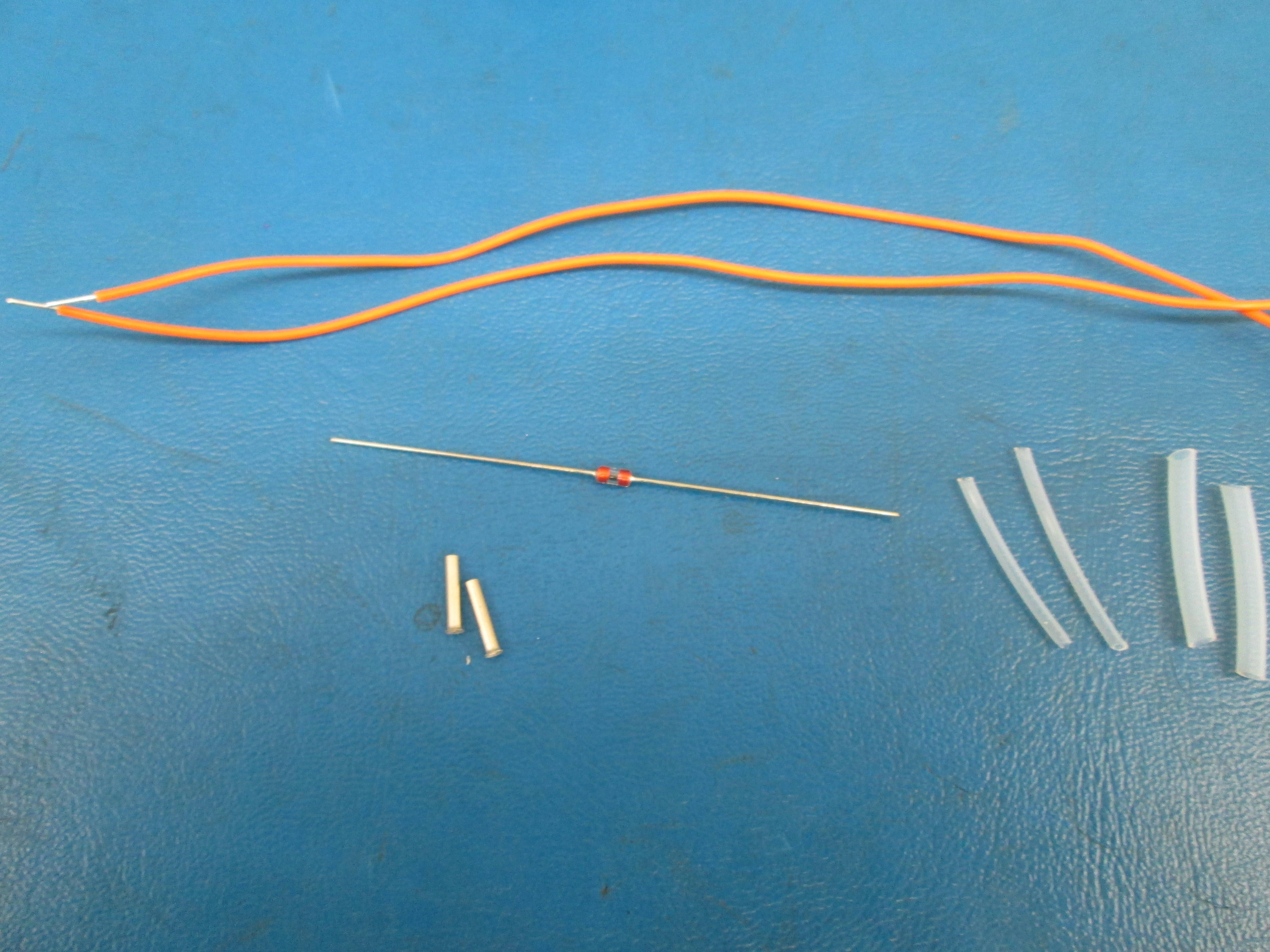
Stripe the orange 24 AWG wire the same as the red
Take the 100 Kilo Ohm axial thermistor and slide a piece of the 20 AWG PTFE insulation over it then take a 20-22 AWG ferrule and slide it flush with the PTFE insulation
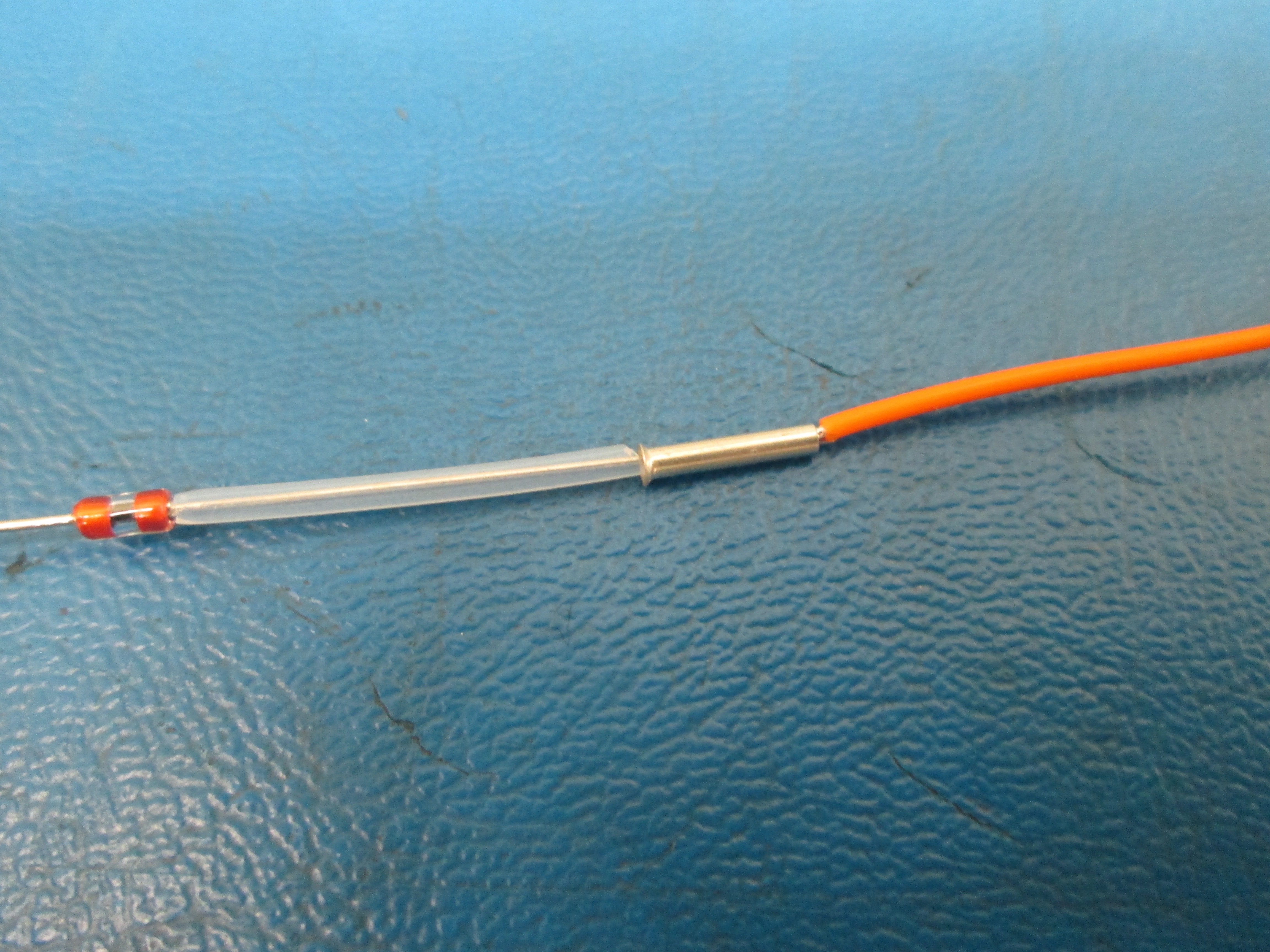
Slide the striped end of the orange wire into the ferrule, the insulation of the wire should be flush with the ferrule
Crimp the ferrule with the wire crimper making sure that the wire or the resistor doesn't slide out
Pull the wire and thermistor to make sure that they are secured within the ferrule and make sure the two are making contact within the ferrule
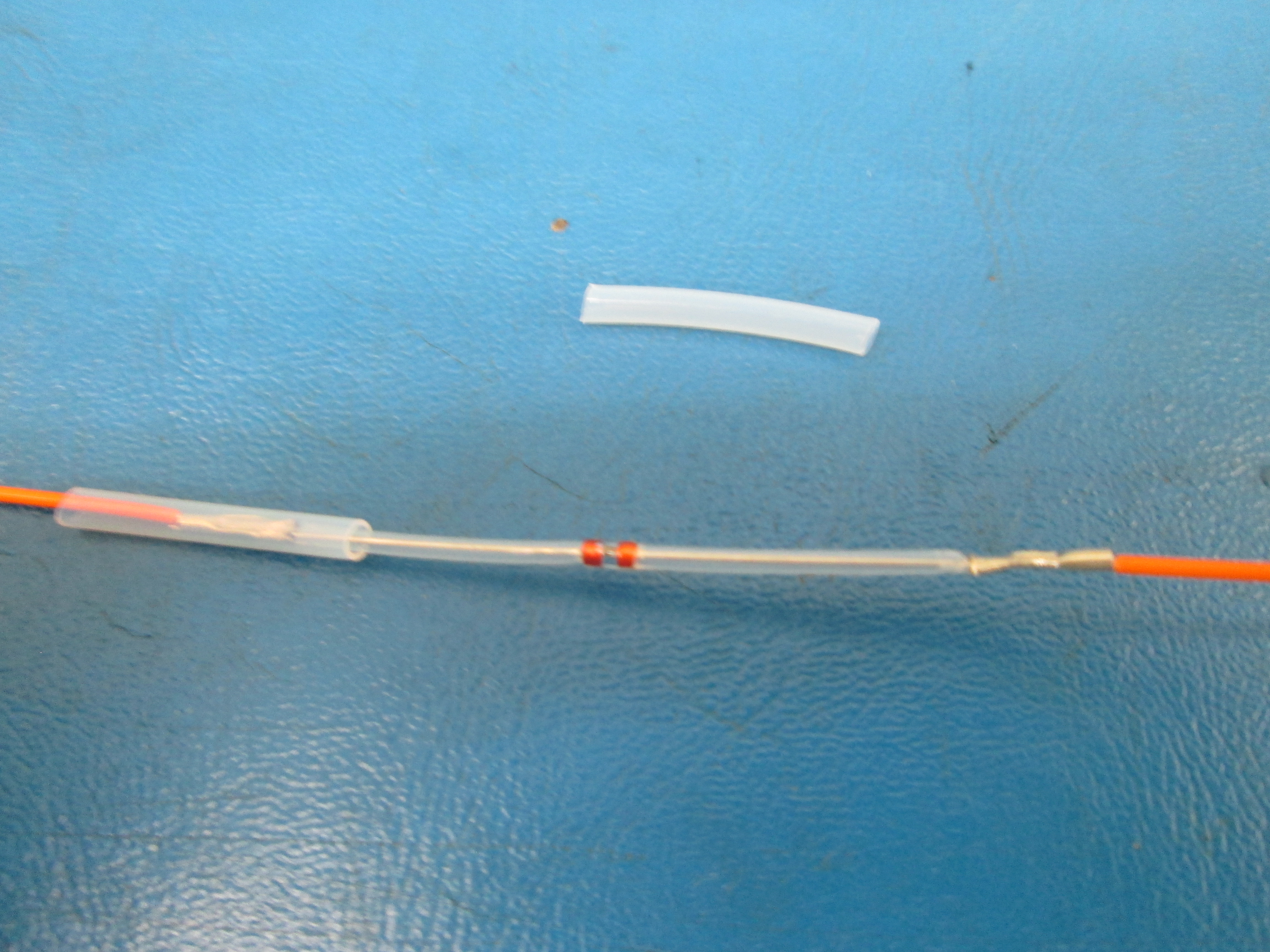
Slide a piece of the 13 AWG PTFE insulation over the ferrule making sure the insulation is centered over the ferrule
Crimp a male terminal connector to the other end of the orange wire that is striped making sure that it is secure with proper contact
Repeat this on the other side of the thermistor, but make sure that you do not add another piece of 13 AWG PTFE insulation or attach another male terminal connector
Take the orange wire assembly and slide it through the small hole in the heater block, center the thermistor within the heater block, you may need to crimp the exposed ferrule extra for it to fit through the heater block
Do the same with the red wire assembly, centering the resistor
Now on the orange wire assembly you can slide the second piece of insulation over the ferrule and center it, and you can now crimp on the second male terminal connector
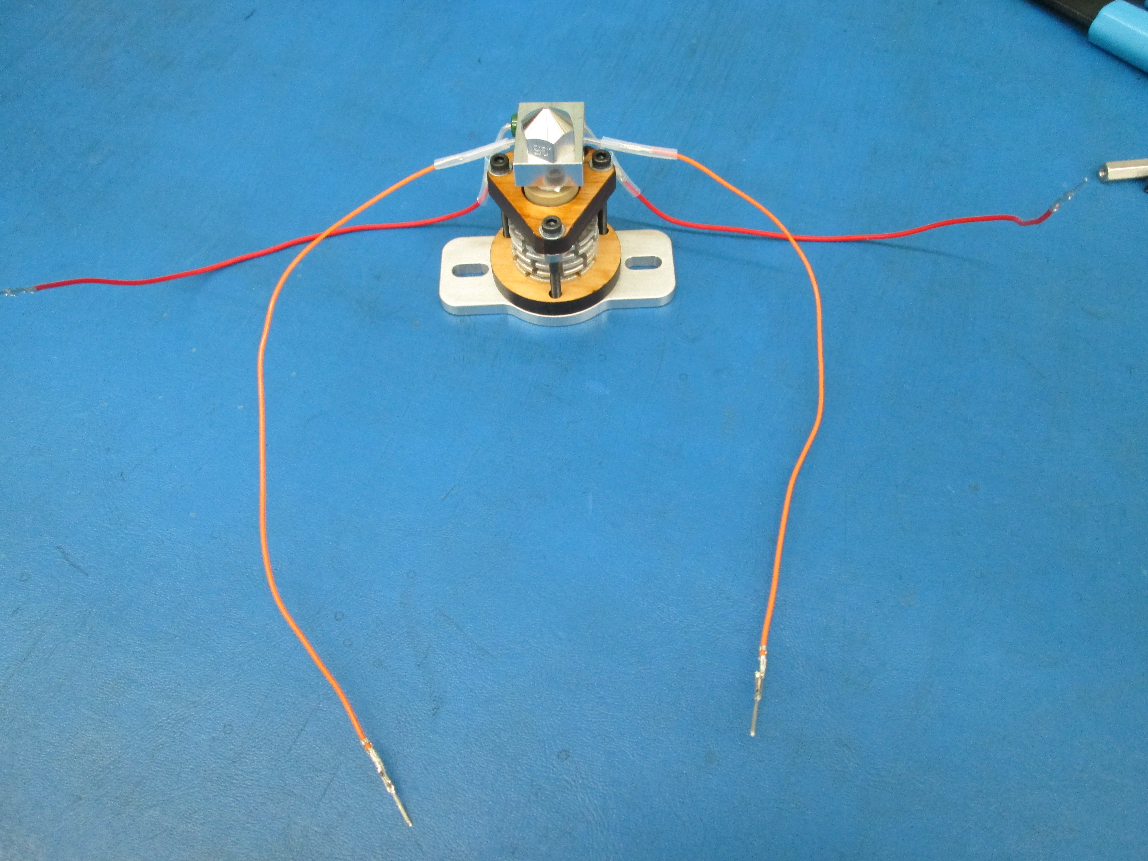
Route one side of the orange wire through the same side cutout in the lower plate, then do the same to the other side
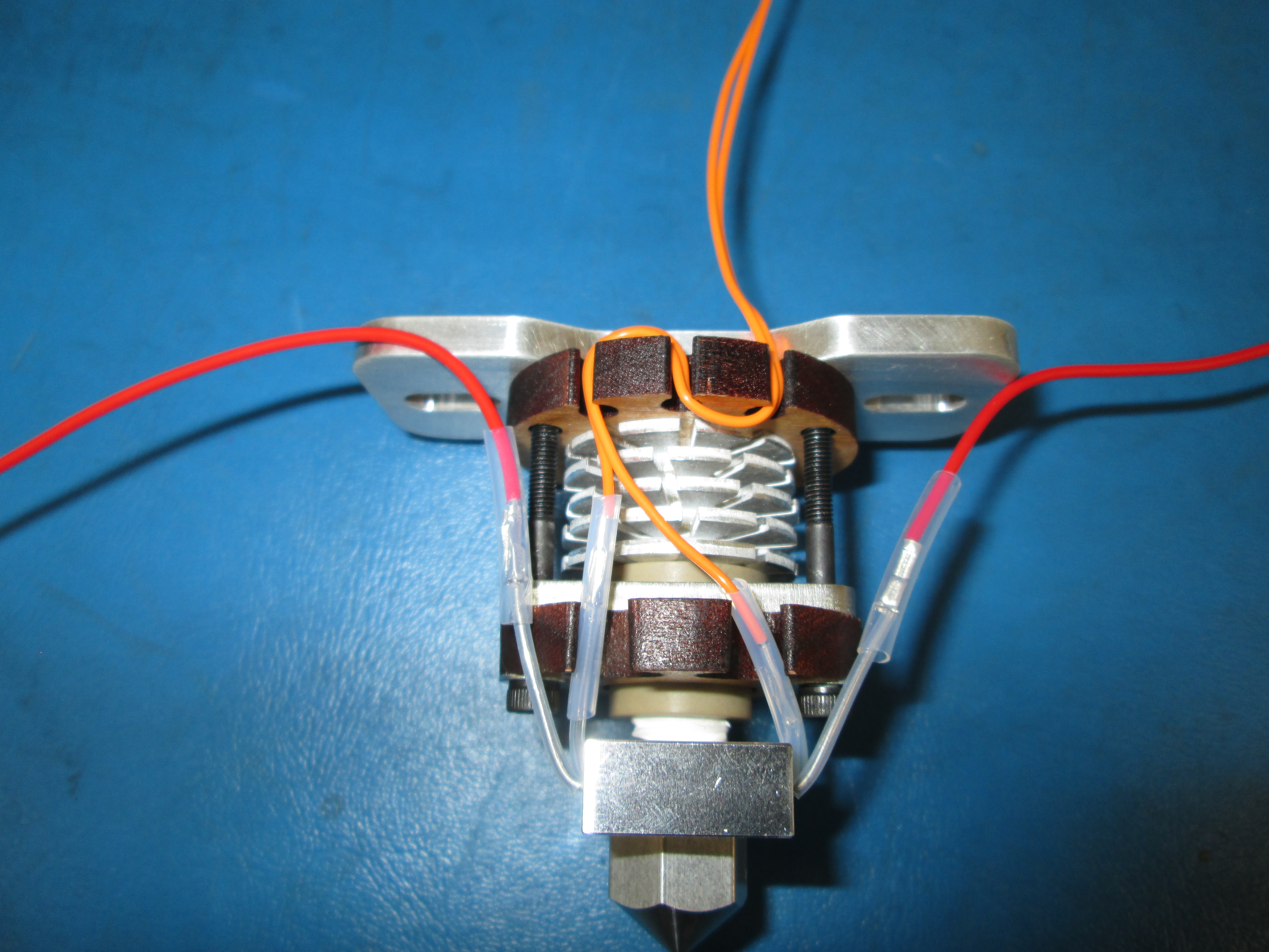
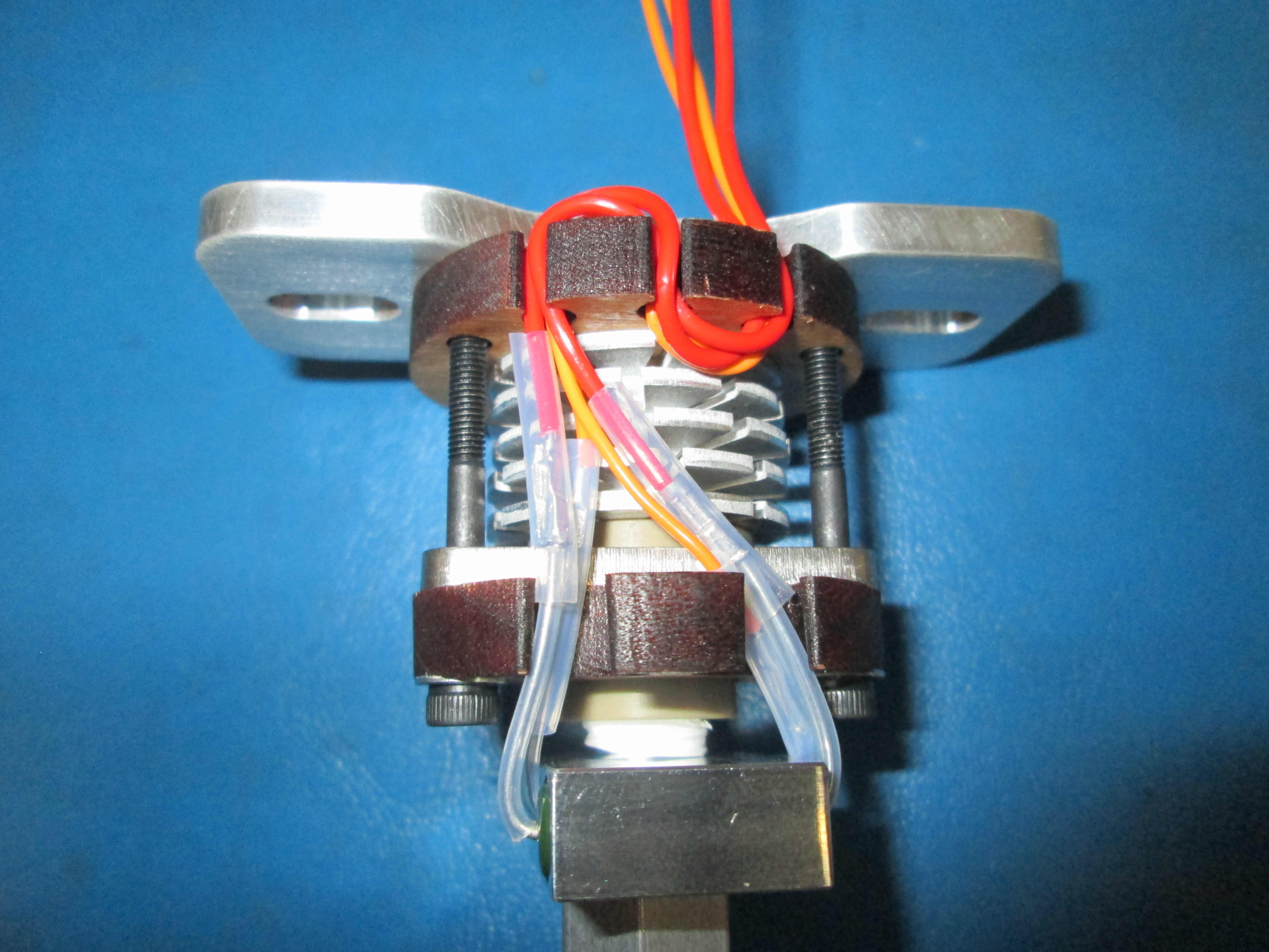
Then with the mount plate oriented to the top of the assembly, route both orange wires through the left cutout in the upper plate, loop it around and down through the middle cutout and finally around and back up through the right cutout
Route the red wires the same way as the orange wires, except slightly twist the wires as you route them through the cutouts as shown
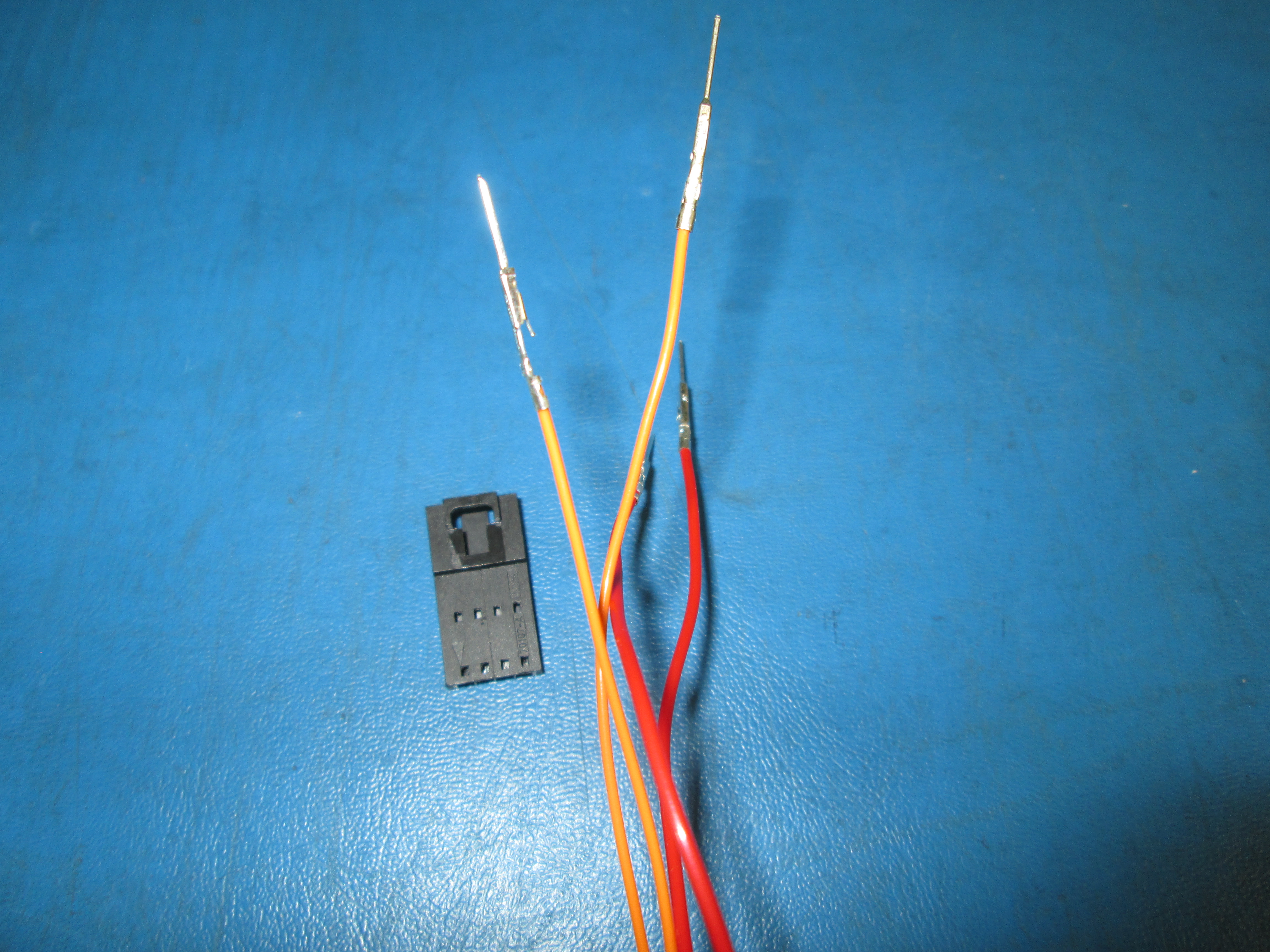
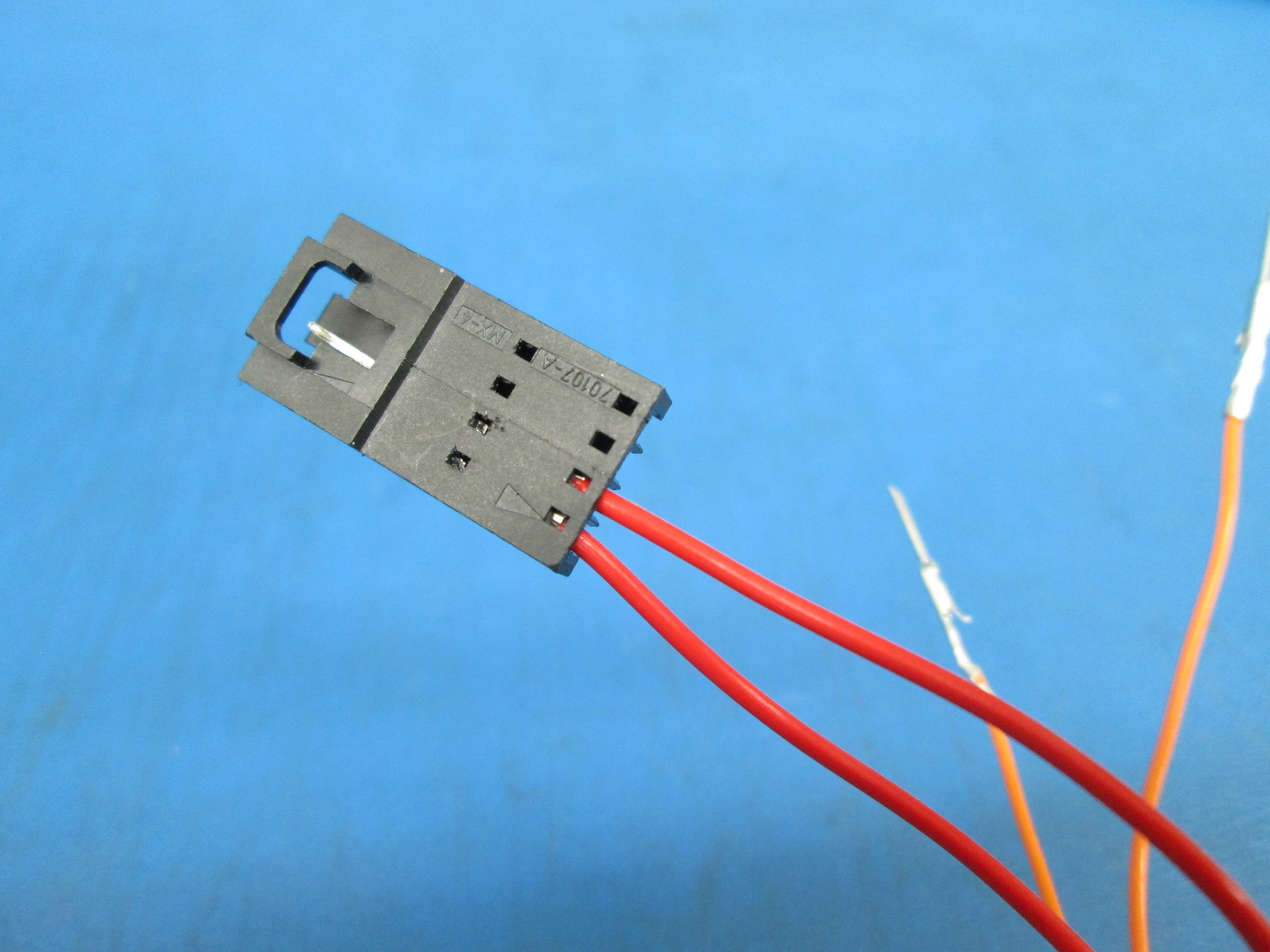
Insert the 4 male terminal connectors into the connector housing as shown, the clips on the male terminals should secure in the housing
Hold the 4 wires under the terminal housing to prevent putting strain on the pins and gently twist all the wires together as shown