Open HardwareAssembly Instructions
Guides for installation and assembly of the LulzBot line of products made by FAME 3D LLC.
Guides for installation and assembly of the LulzBot line of products made by FAME 3D LLC.
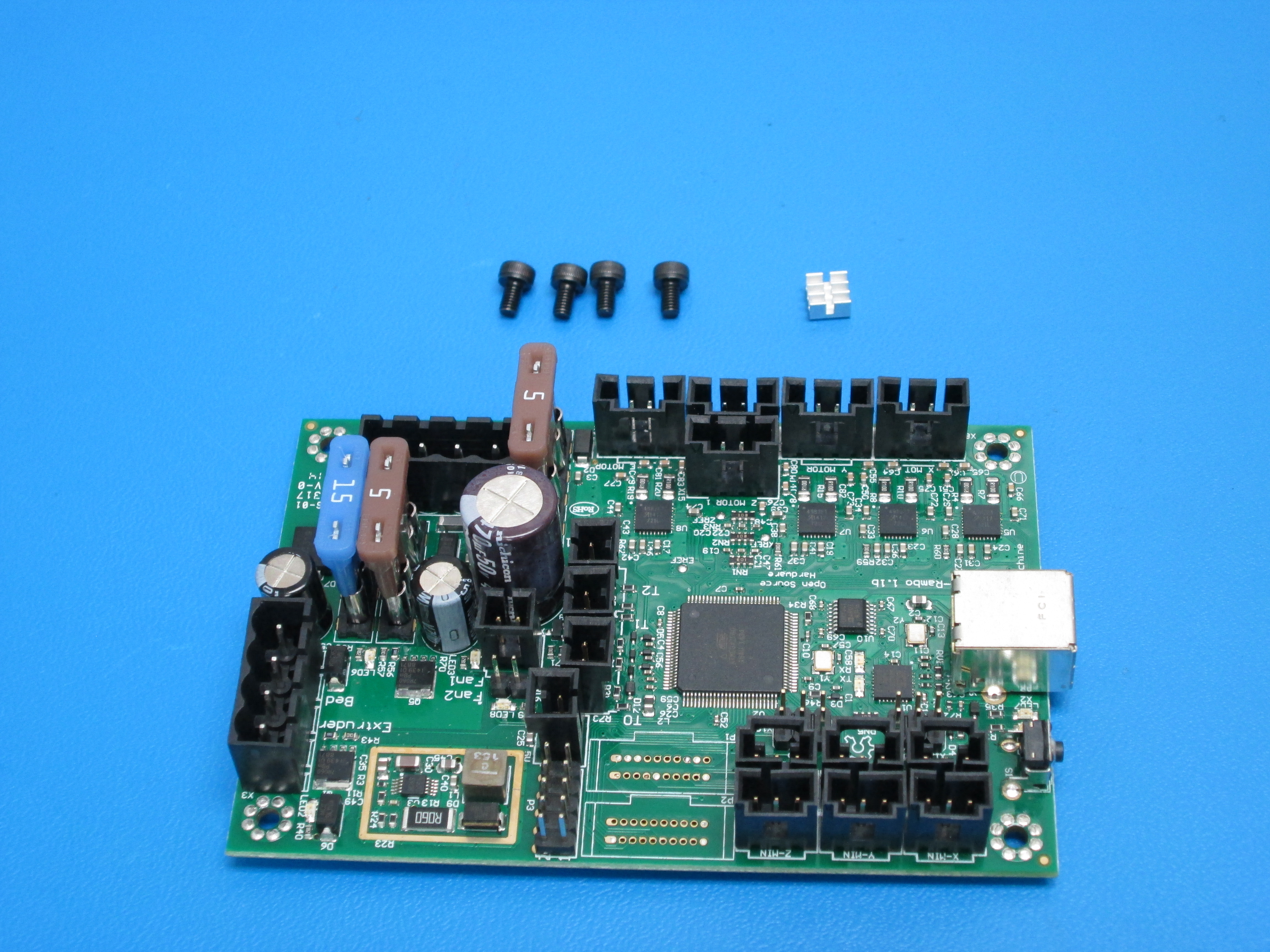
Components Required
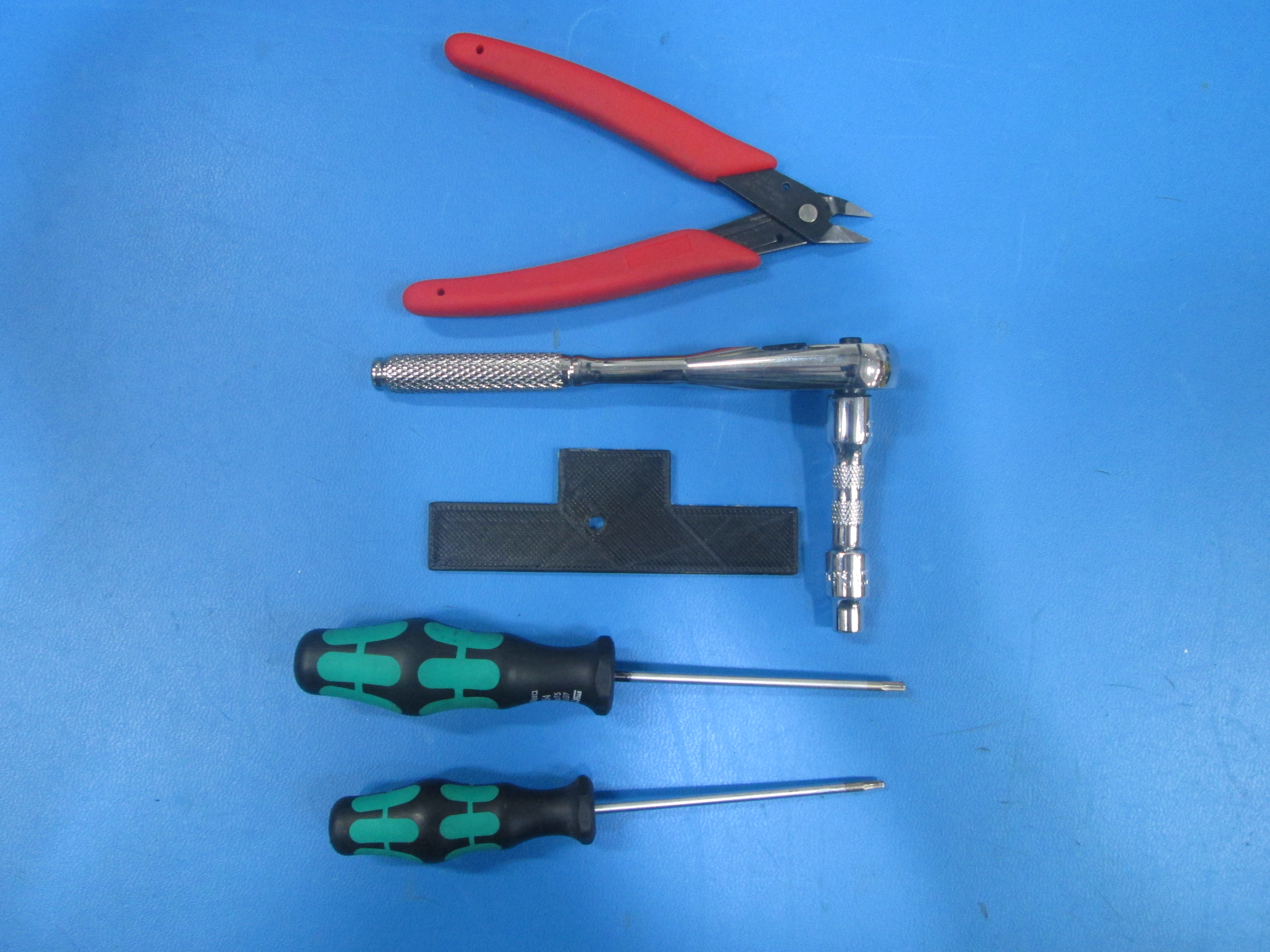
Tools Required
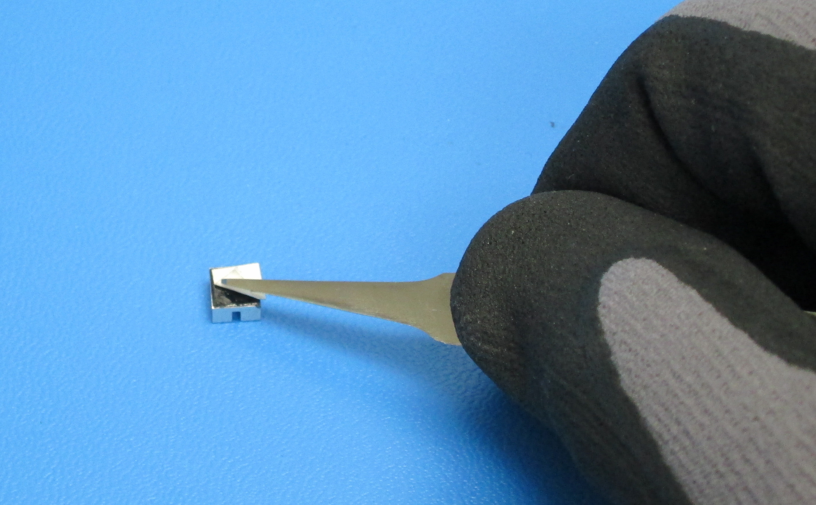
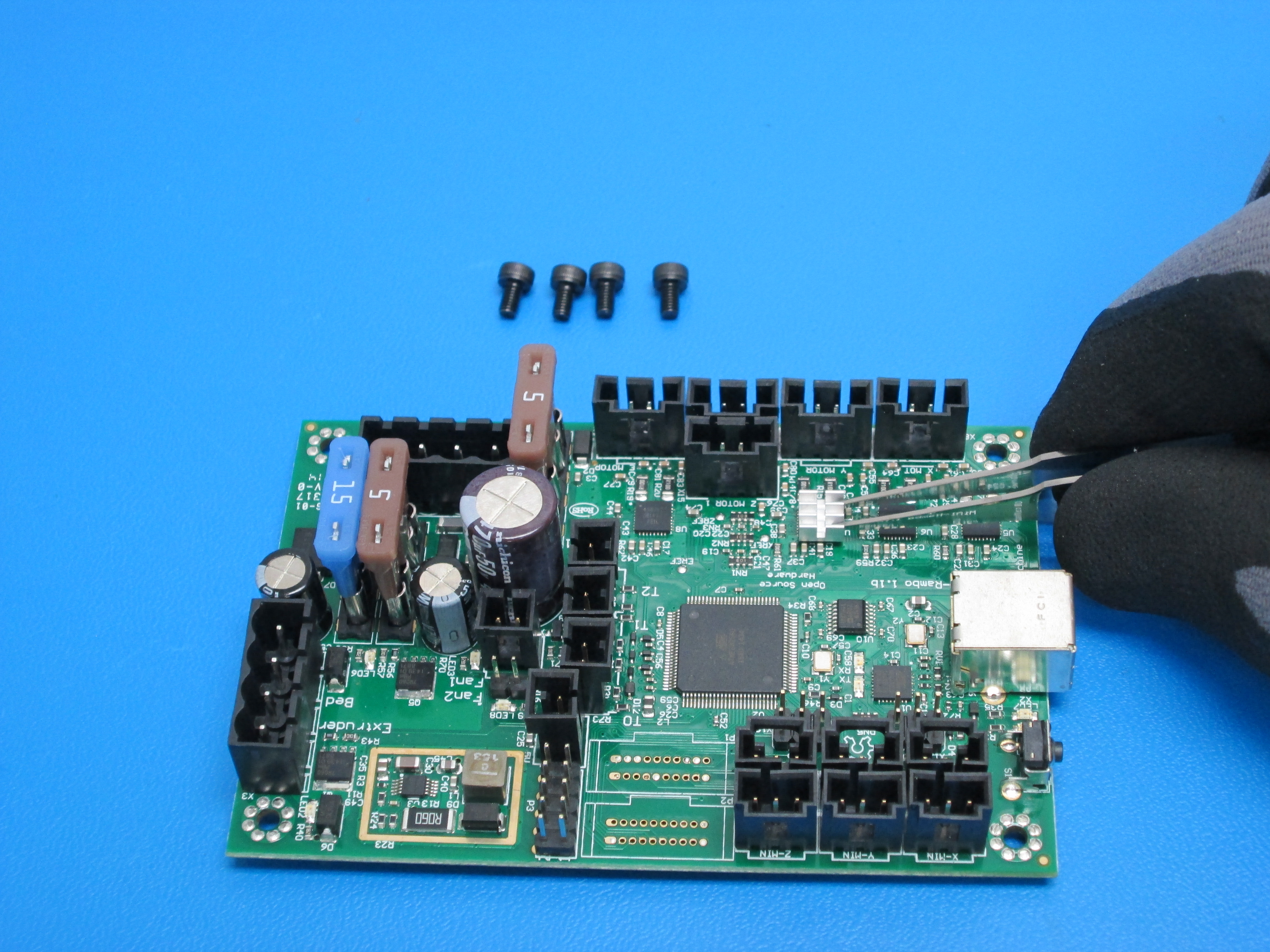
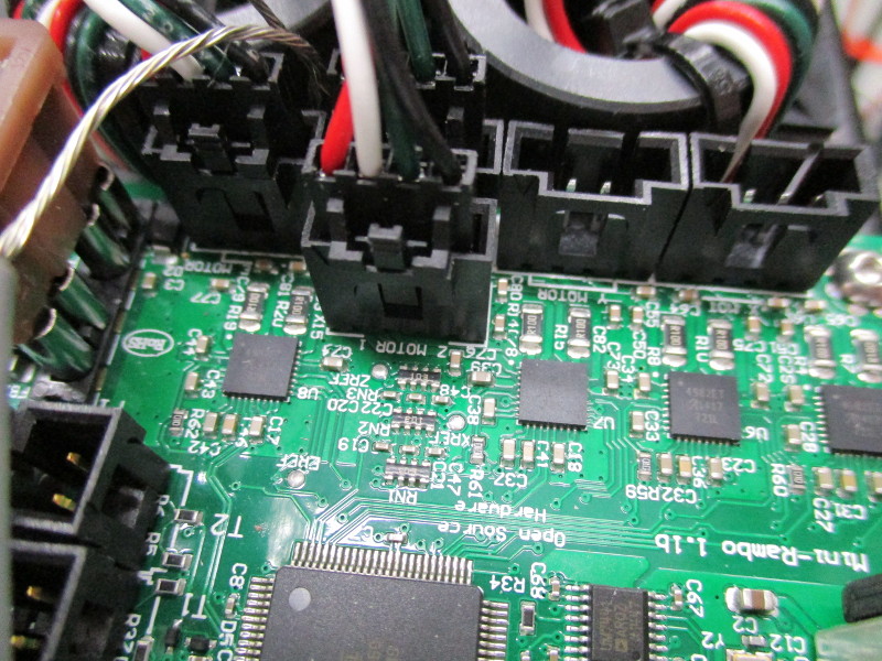
Attach the heat sink, shown with Rambo and hardware, to the mini Rambo Z axis chip (Ref Des U7).
Remove the adhesive backing from the heat sink. Squarely align the heat sink with the U7 chip, press down gently on the chip FOR 7 TO 10 SECONDS to set the adhesive.
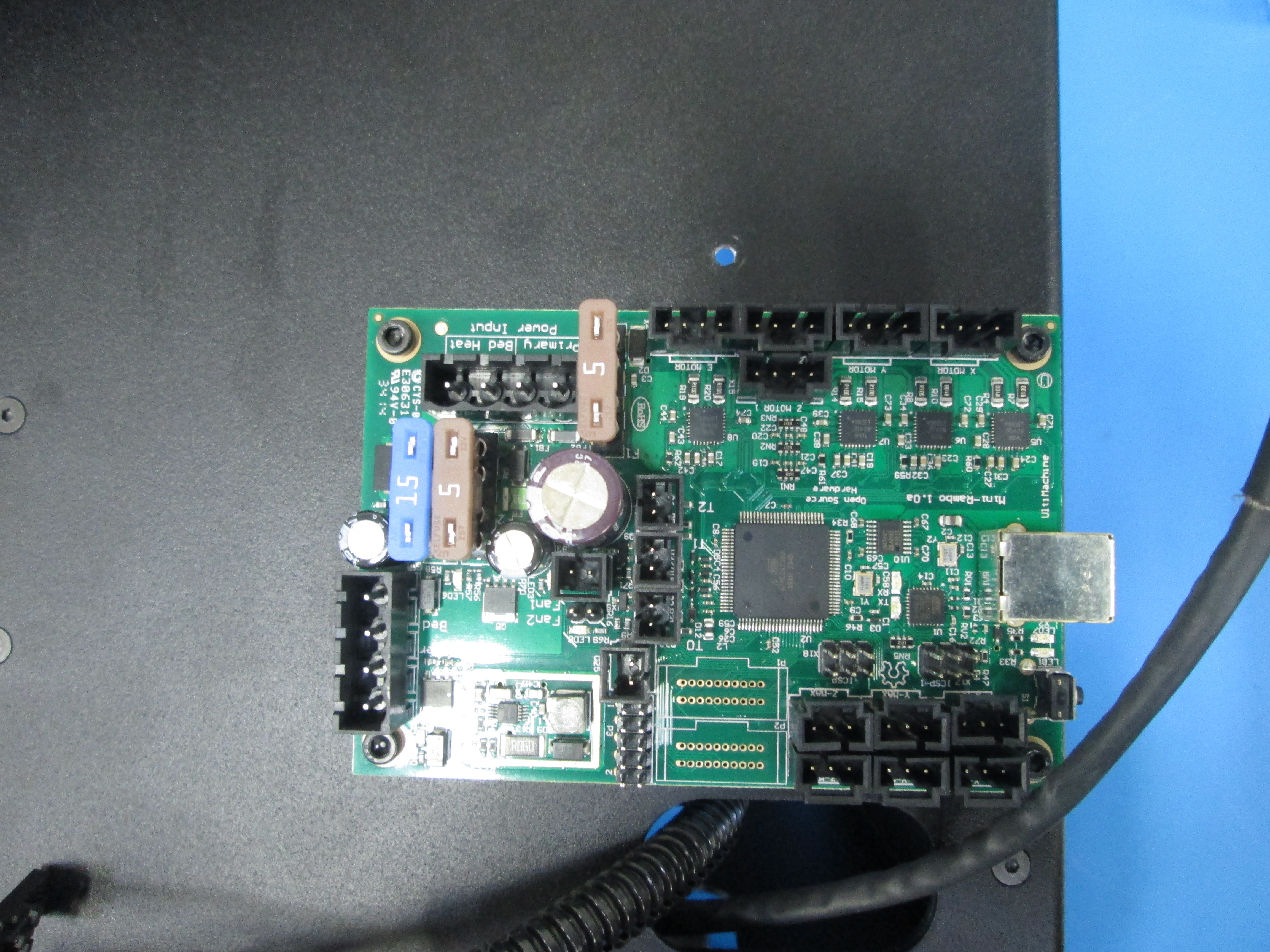
Attach the mini Rambo to the outside left frame plate using 4x M3x5 SHCS as shown, note orientation.

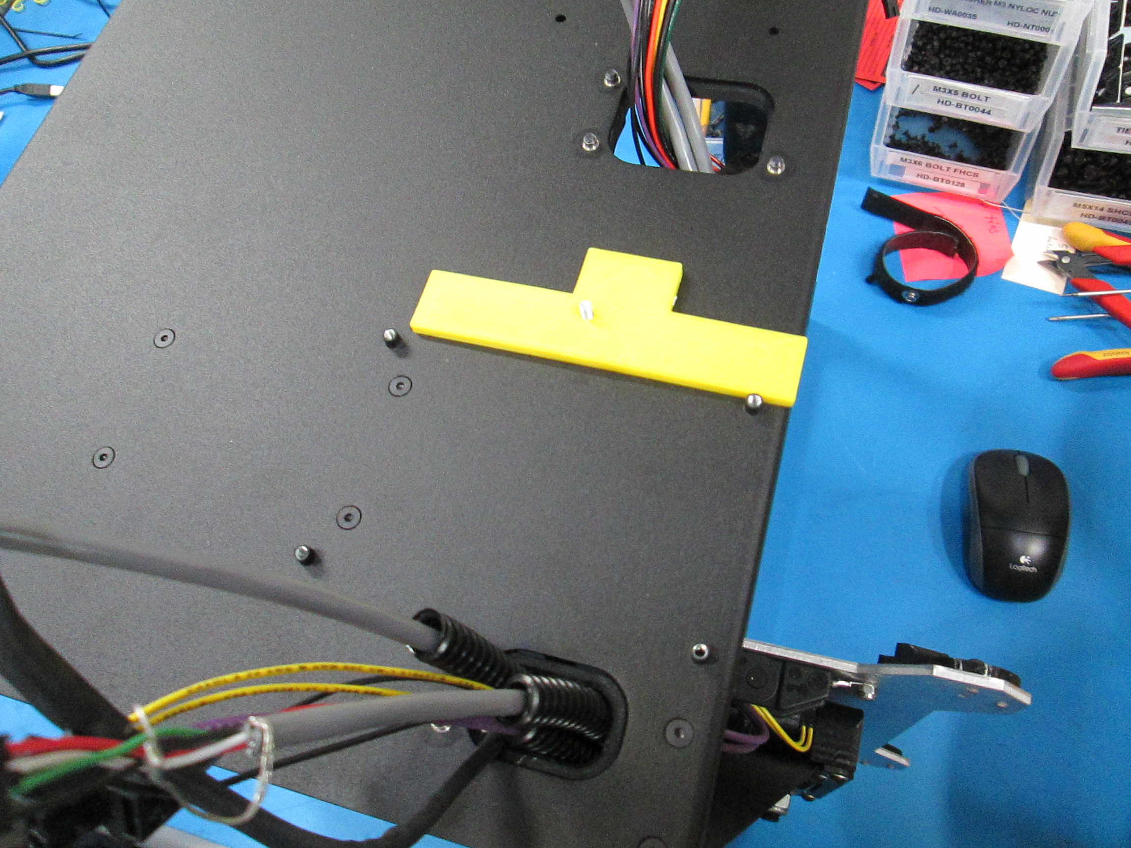
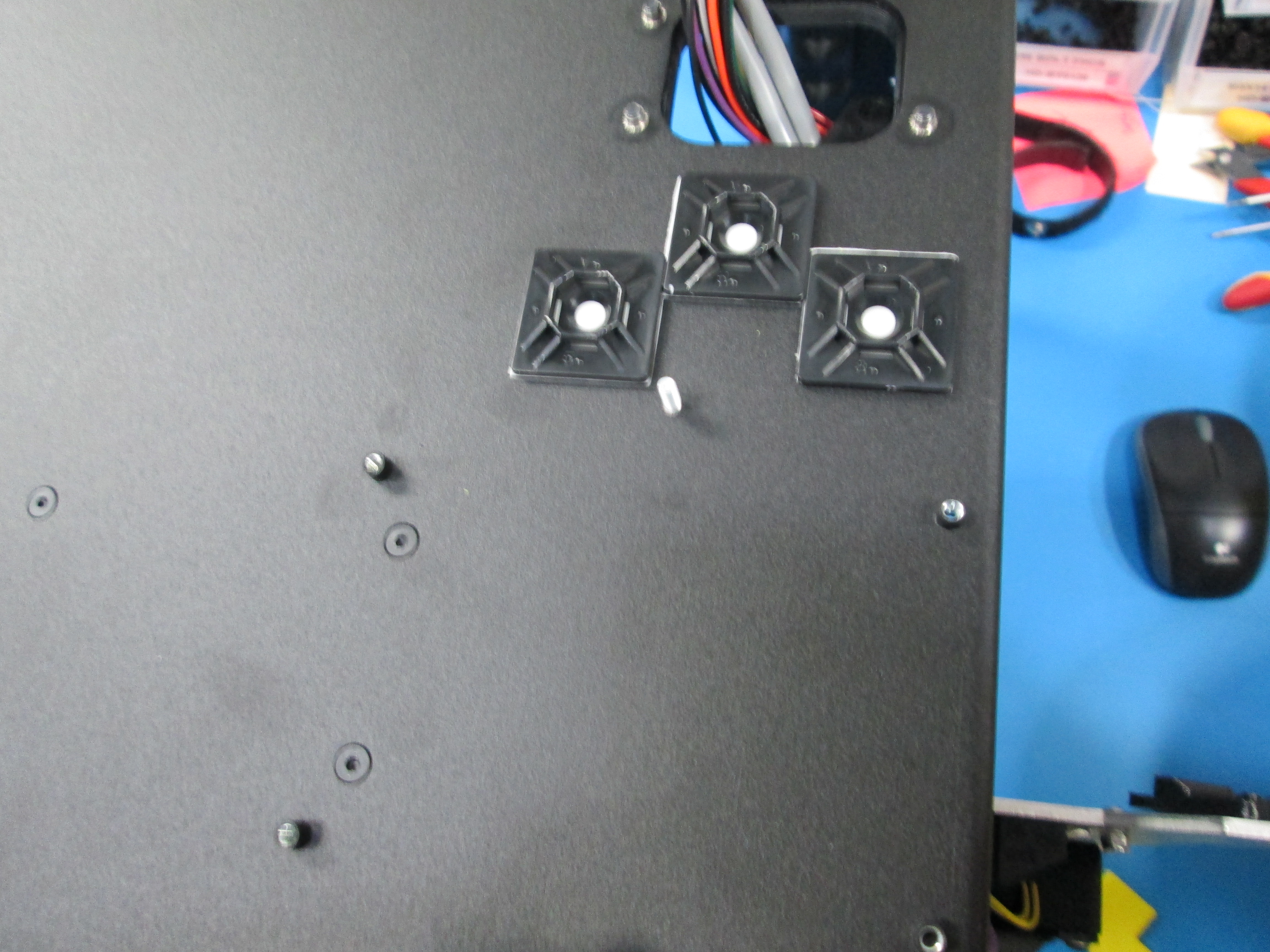
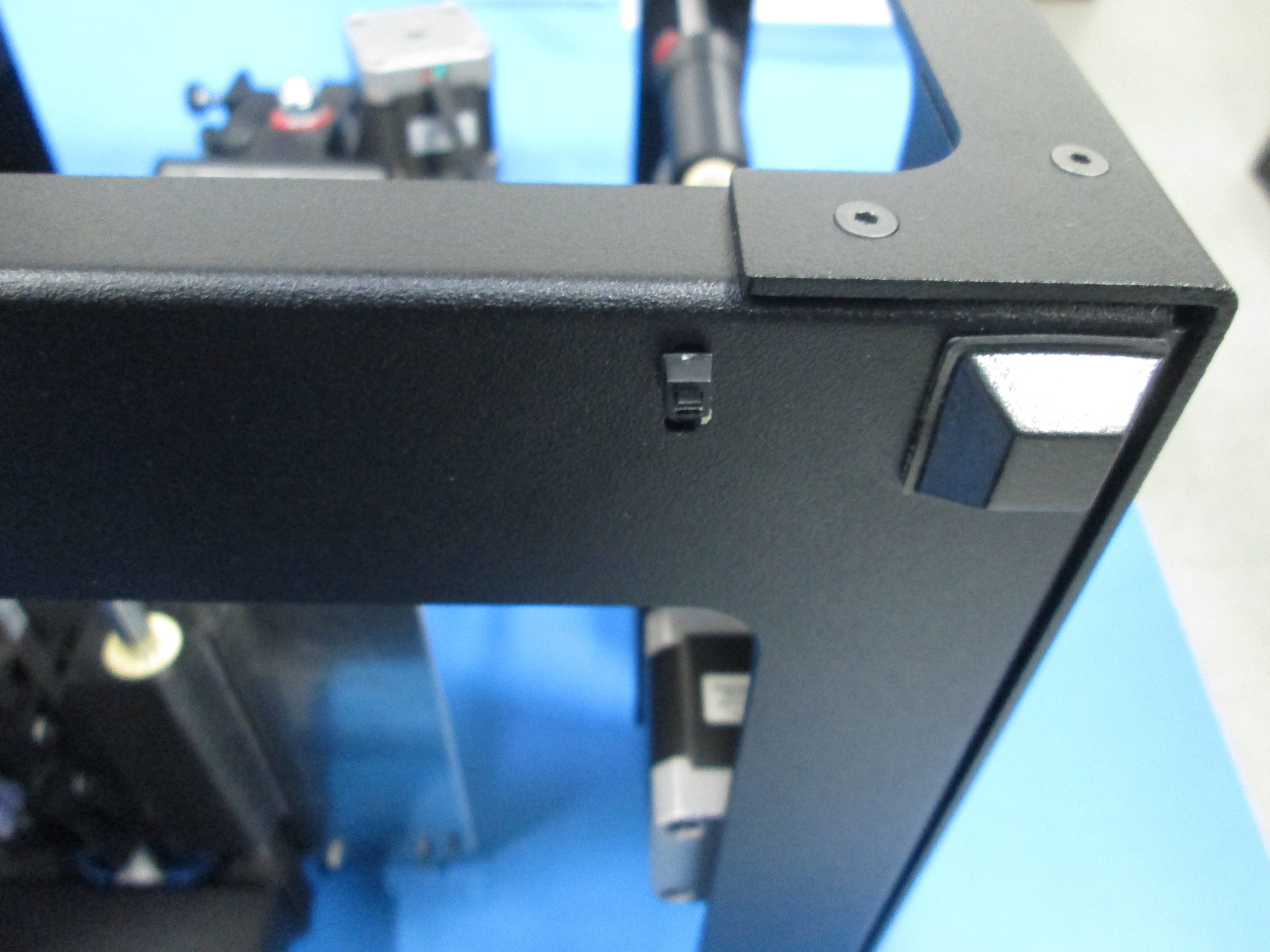
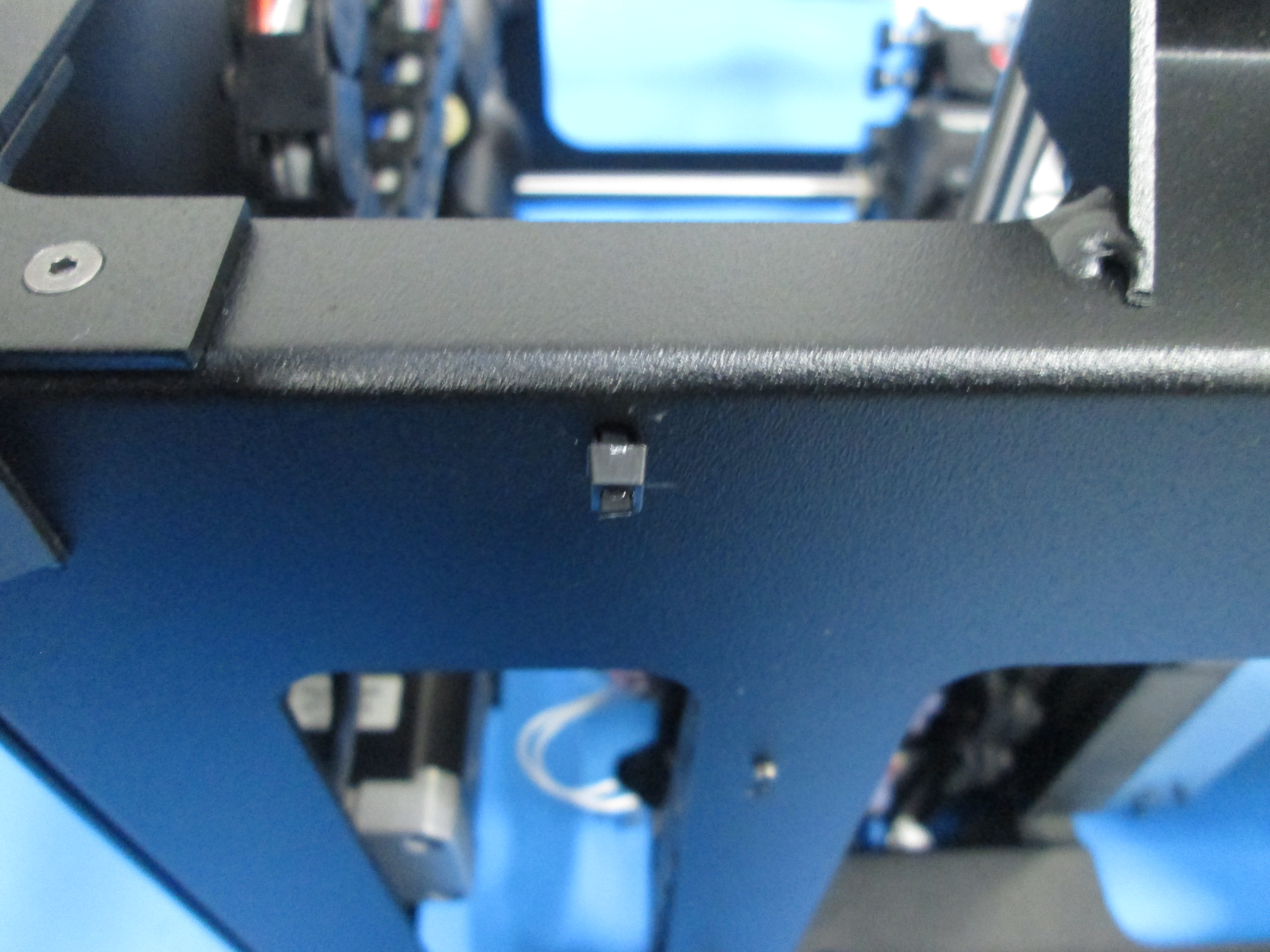
Add three tie down mounts to the frame above the RAMBo mount.
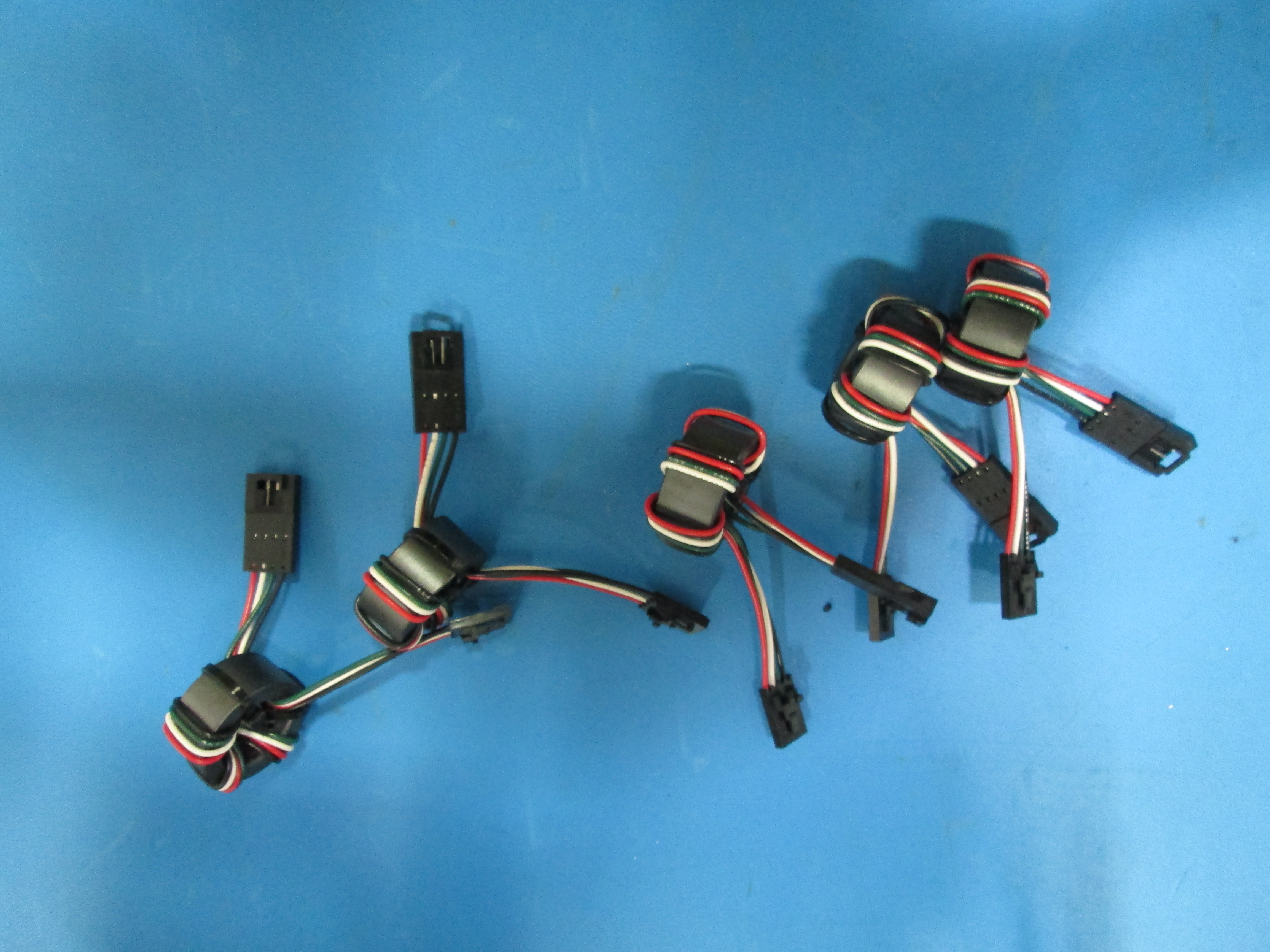
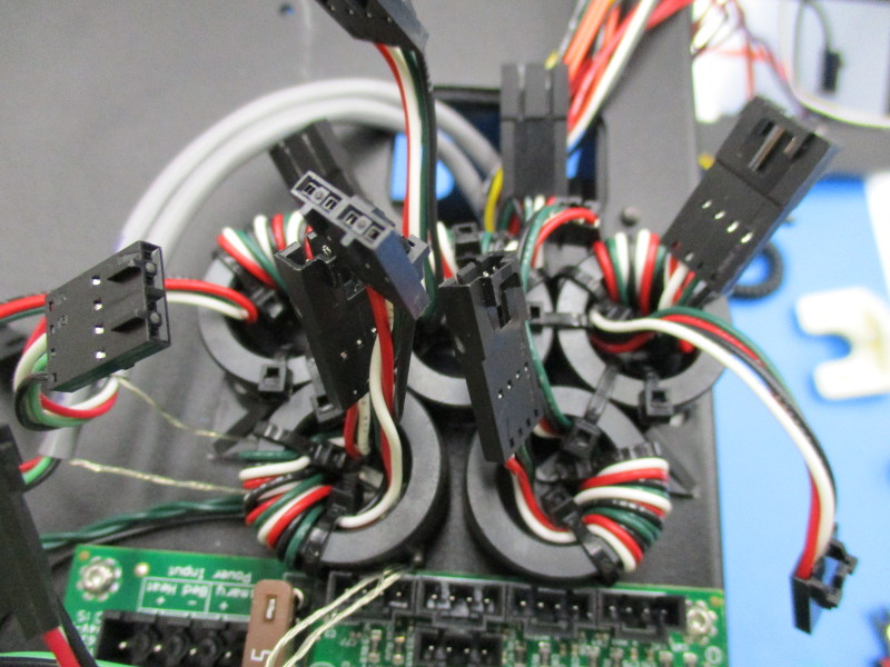
When installing the ferrites you will need to pay special attention to the orientation shown in the pictures.
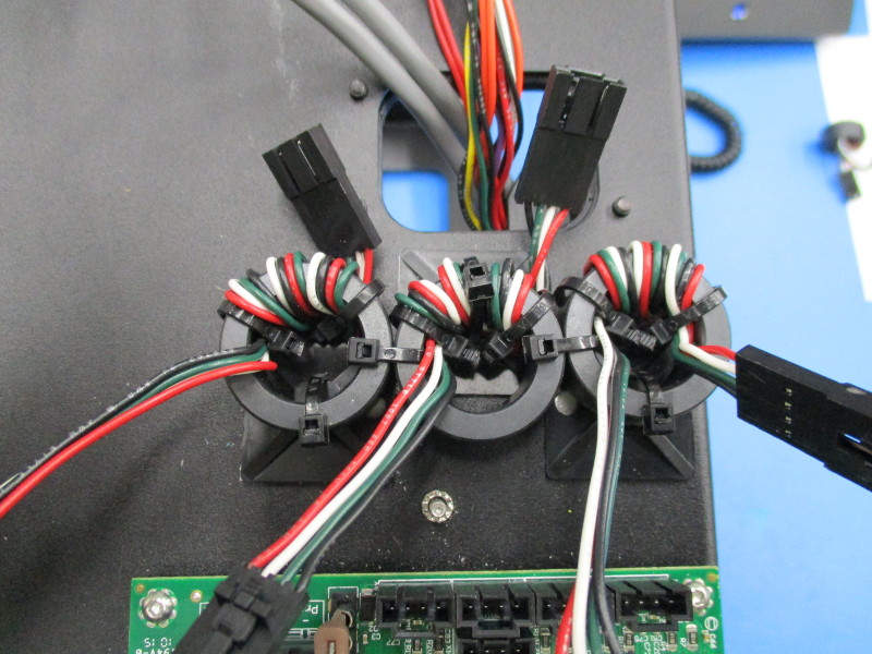
Install three ferrites onto the tie down mounts and secure.
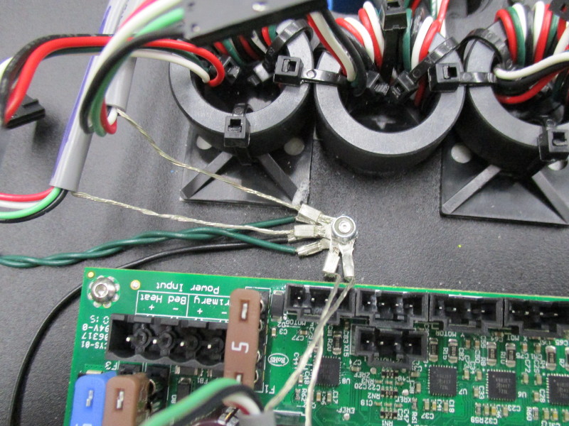
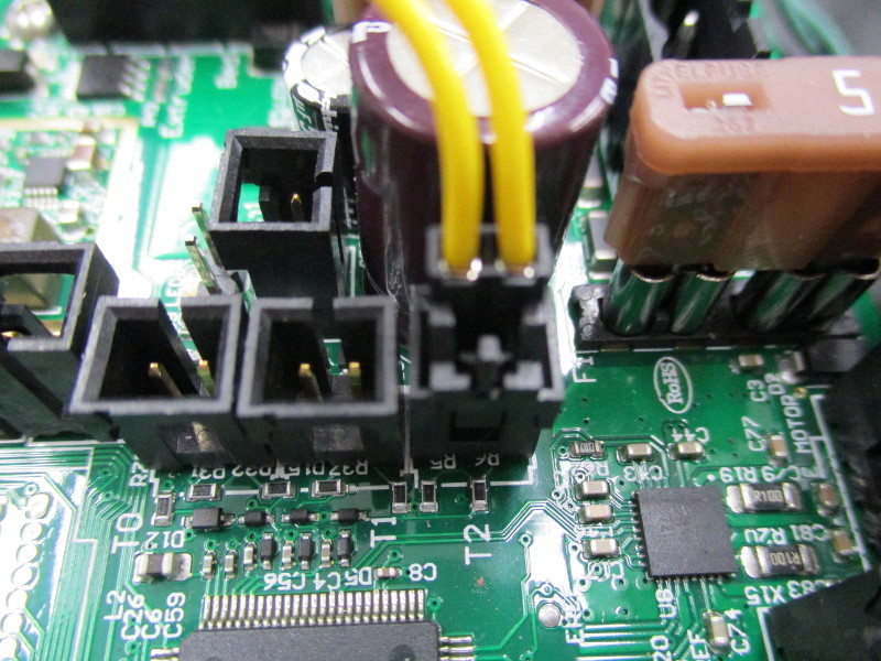
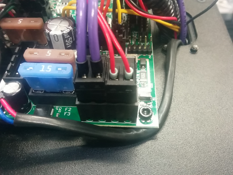
CAUTION! Be sure to arrange the Y motor and Z right motor grounds as shown to prevent shorting against the 5 amp fuse on the left. Tighten the nylon locking nut.
Place the grounding wires on the ground post as shown.
Install two additional ferrites between the rambo and the three previously installed ferrites and secure.
Install two additional tie down mounts to the frame below the RAMBo as shown.
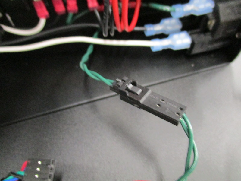
Install the X-min ferrite assembly (green and black wires wrapped around a ferrite core) onto the tie down mount shown and secure.
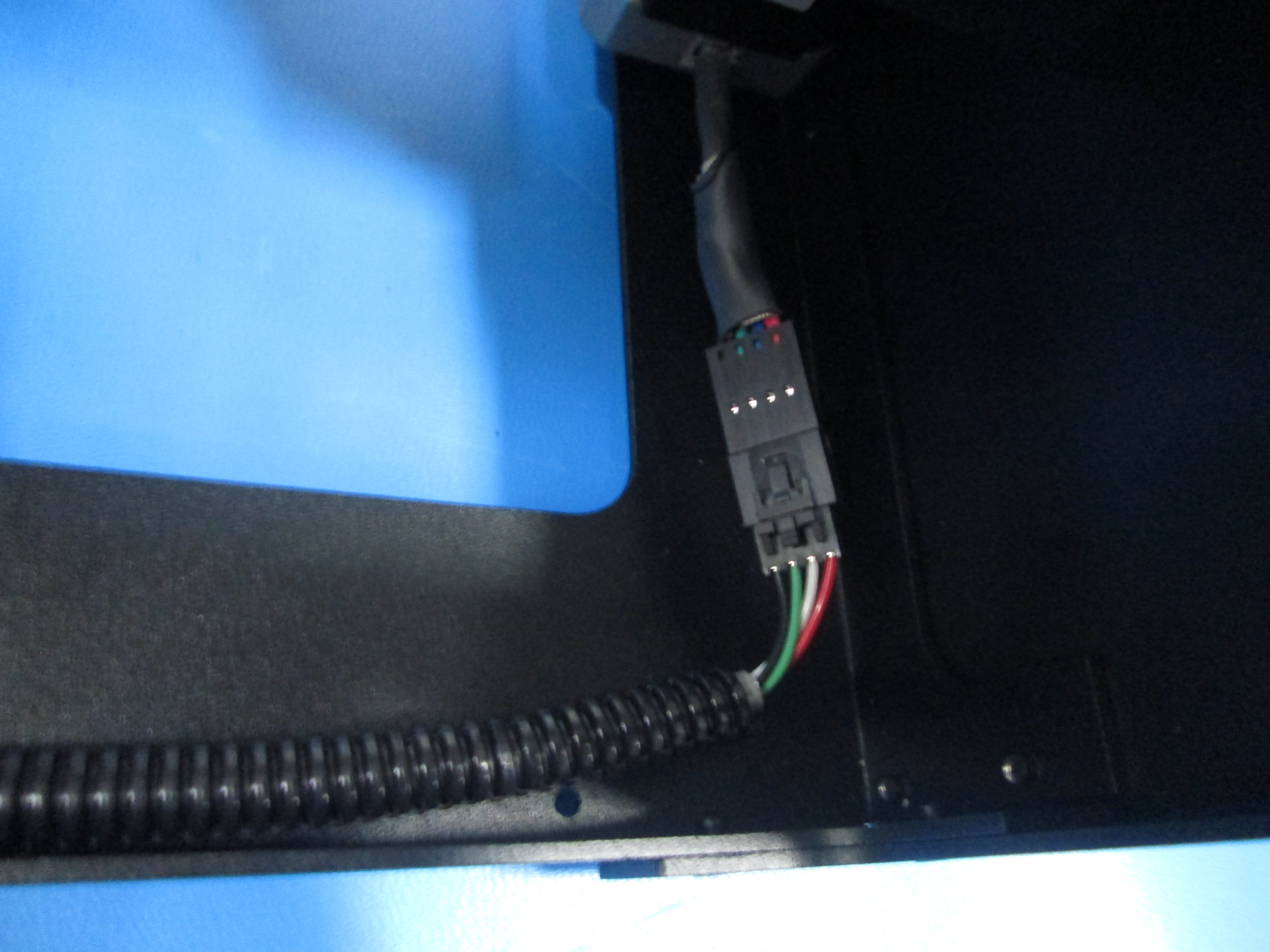
Install a clamp-on ferrite to the loose hookup wires, DO NOT include the extruder heater circuit.
Install a clamp-on ferrite to the extruder heater circuit.
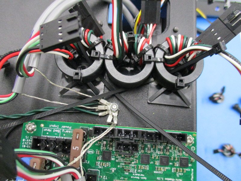
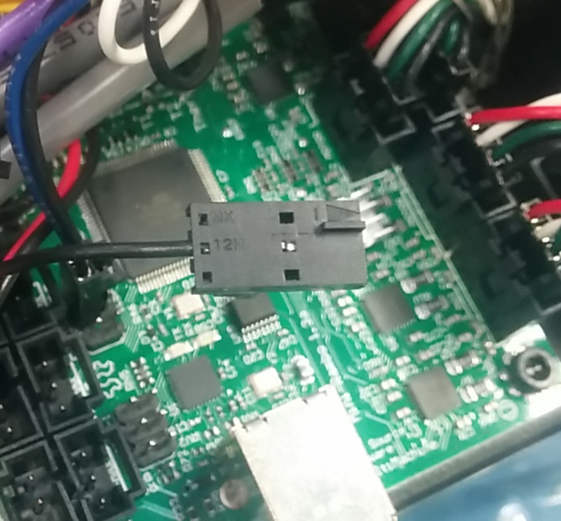
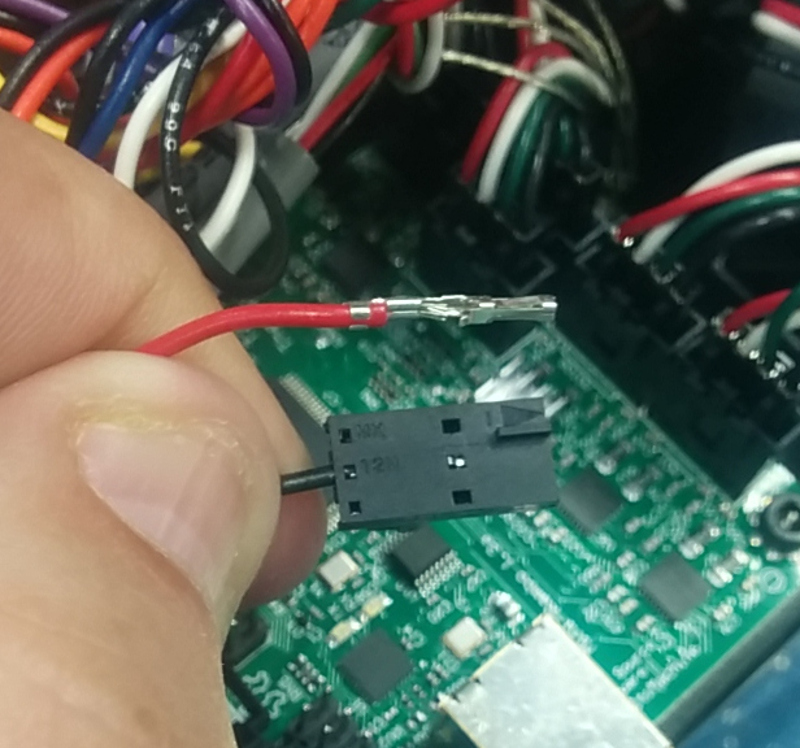
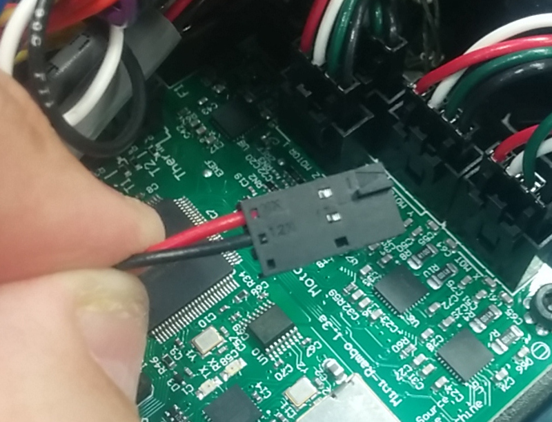
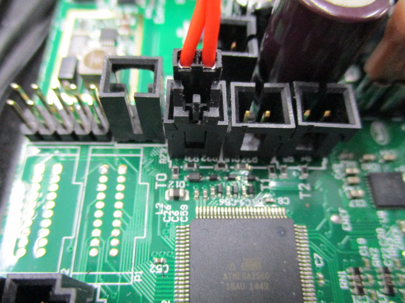
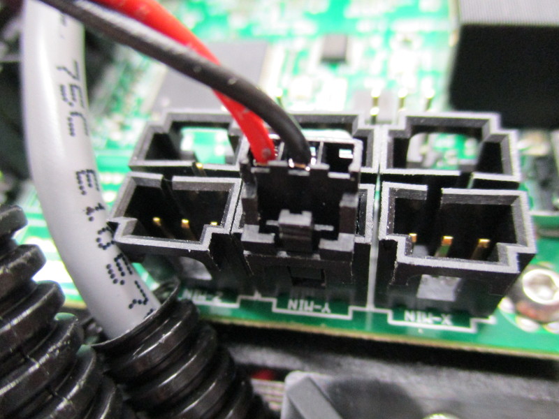
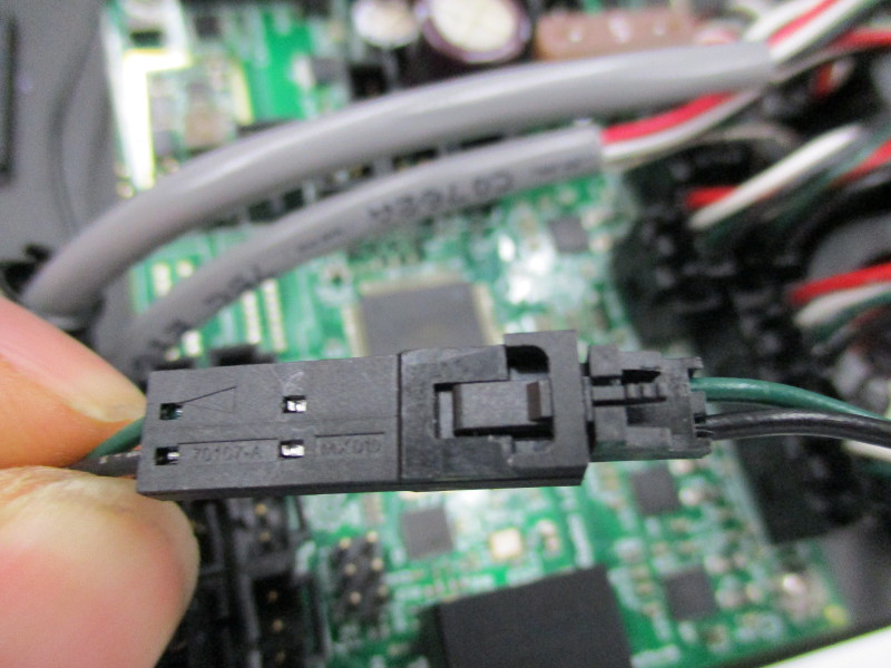
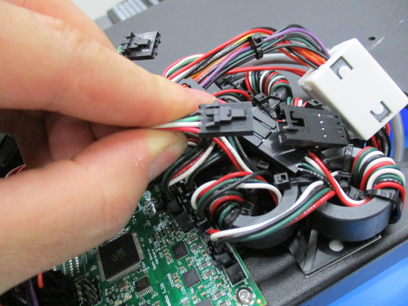
Locate the loose red wire with terminal installed, insert into the connector (position1, Triangle on connector) of the three position connector that has only one black wire installed (at posiiton 2), Plug in the z min connector on the RAMBo

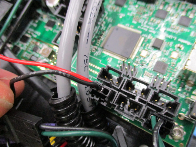
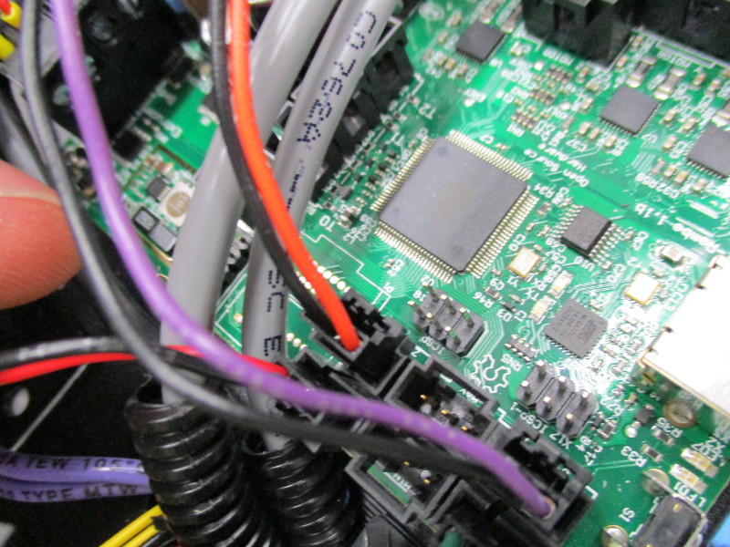
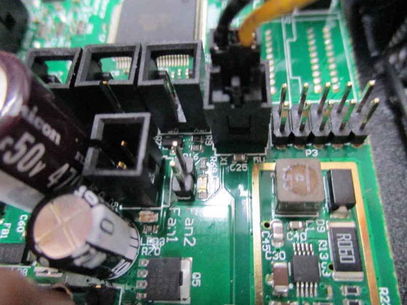
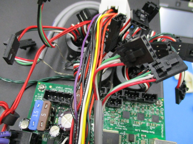
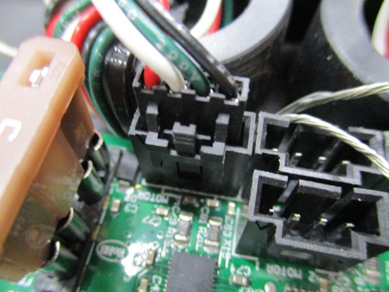
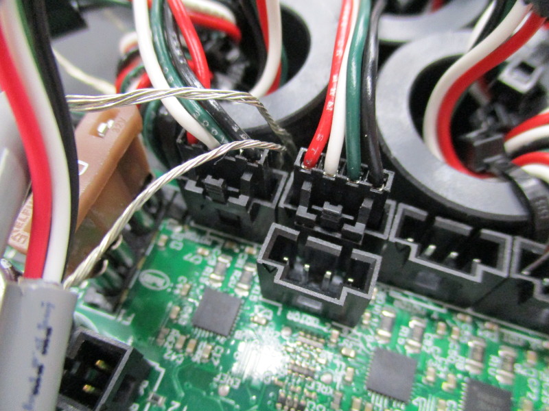
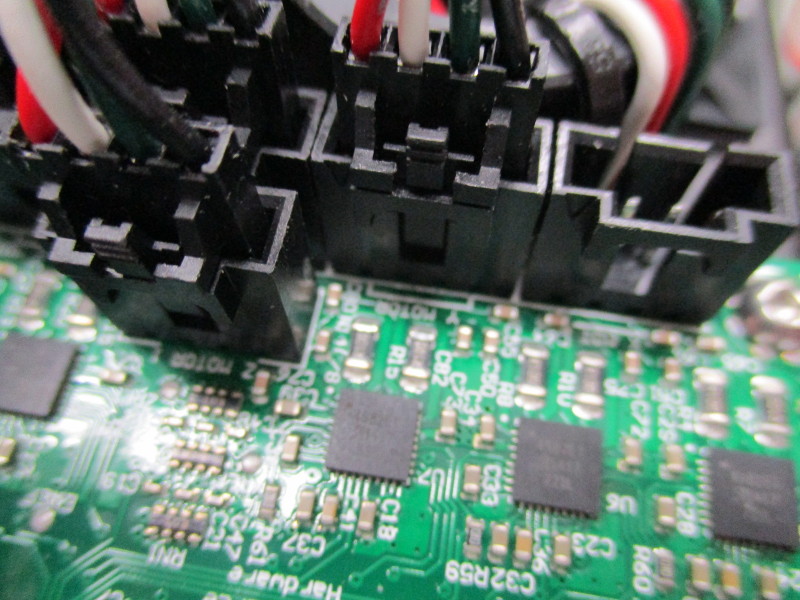
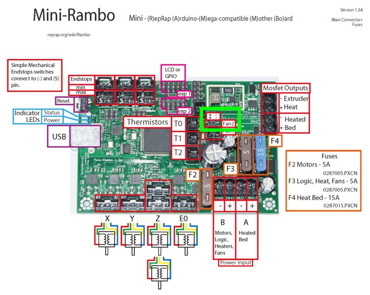
Connect wires in the indicated order to their positions on the RAMBo
-*X-Max
-*Z-Max
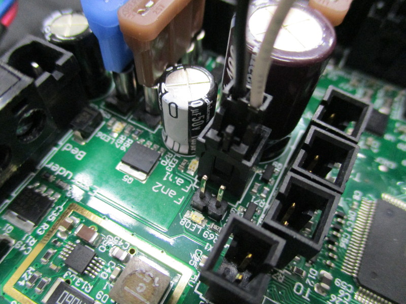
-*24Vdc fan
-*5Vdc fan
-*T0
-*T2
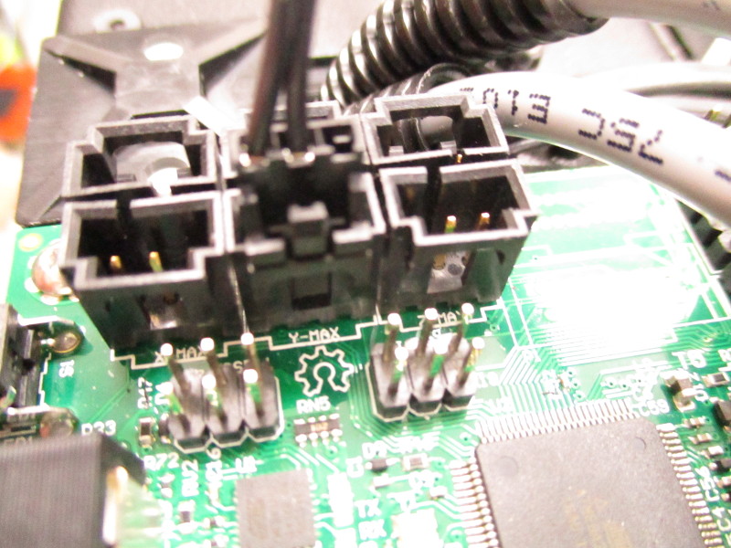
-*Y-Max
-*Y-Min
-*Z-Min
-*X-Min
-*Extruder Heater
-*E Motor
-*Z motor Left (Note the ground straps between the E and Z connectors. It is crucial they are ran like this to prevent shorting of the 5 amp fuse.)
-*Z motor Right
-*Y Motor
-*X Motor
-*Case Fan
-*DC Power
-*Left panel case ground
-* Double check your cable routing to be sure you don't have any twists or kinks in the wiring.


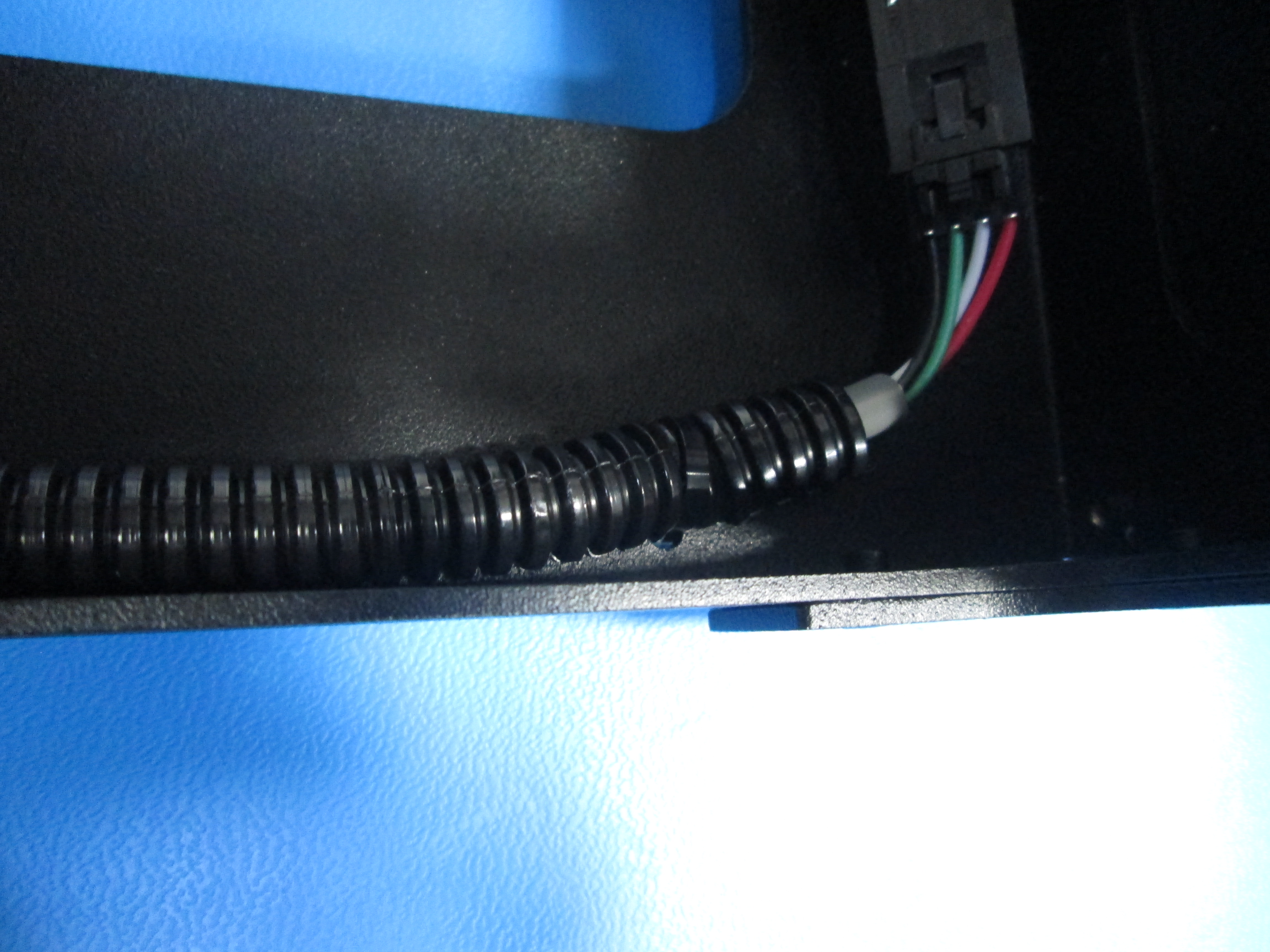
Add the Z motor extension as shown.
Connect the Z motor extension to the Z right motor.
Make sure the end of the extension you plug into the motor is the end without the ground lug.

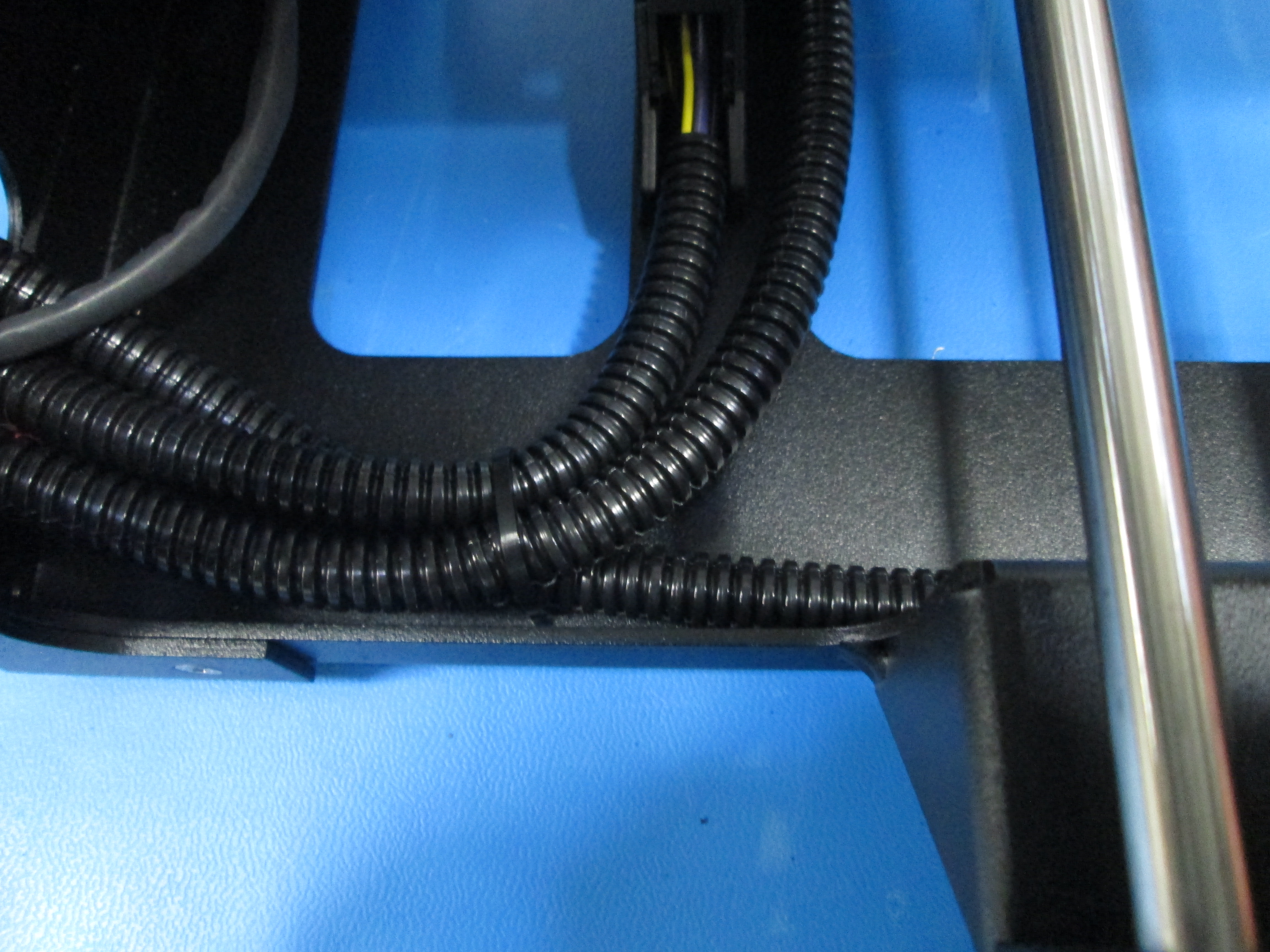
Add the Y motor extension as shown.
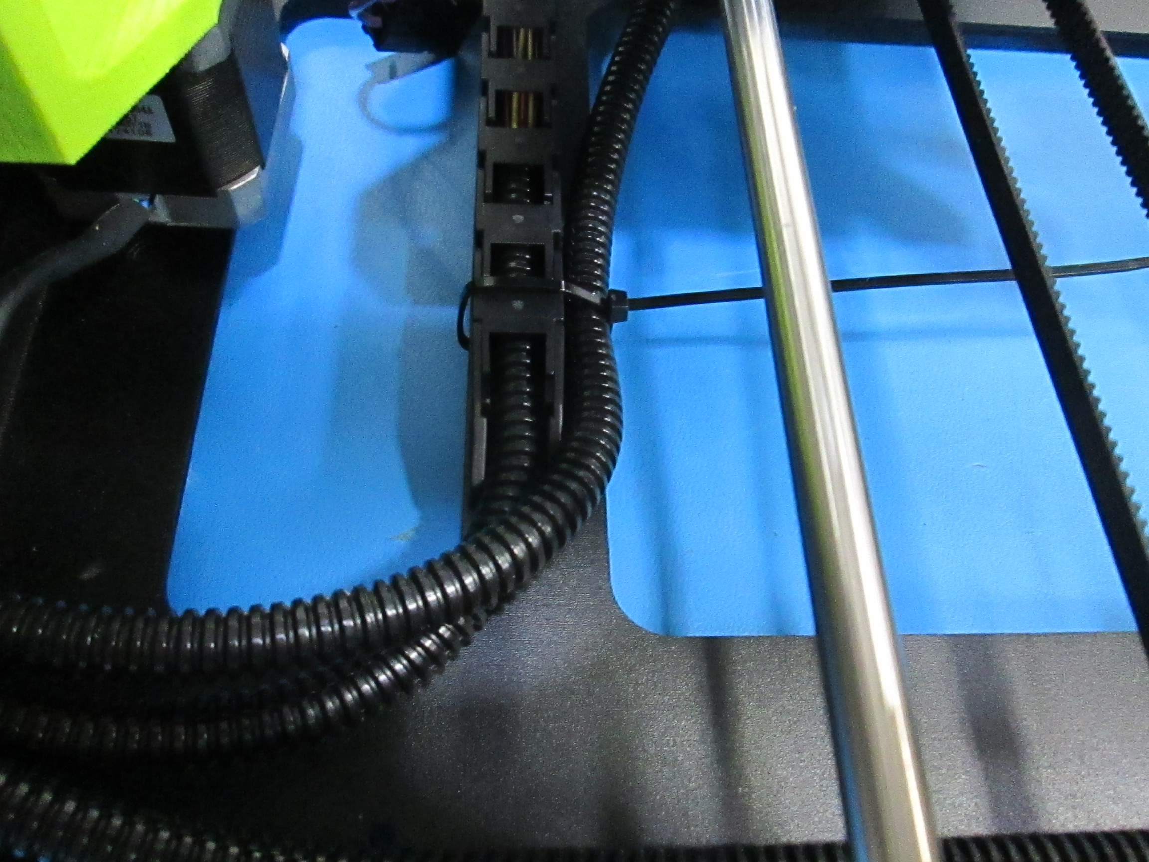
Connect the Y motor extension and zip tie in place as shown.
Make sure the end of the extension you plug into the motor is the end without the ground lug.
Also, Zip tie the Z motor extension in place as shown.

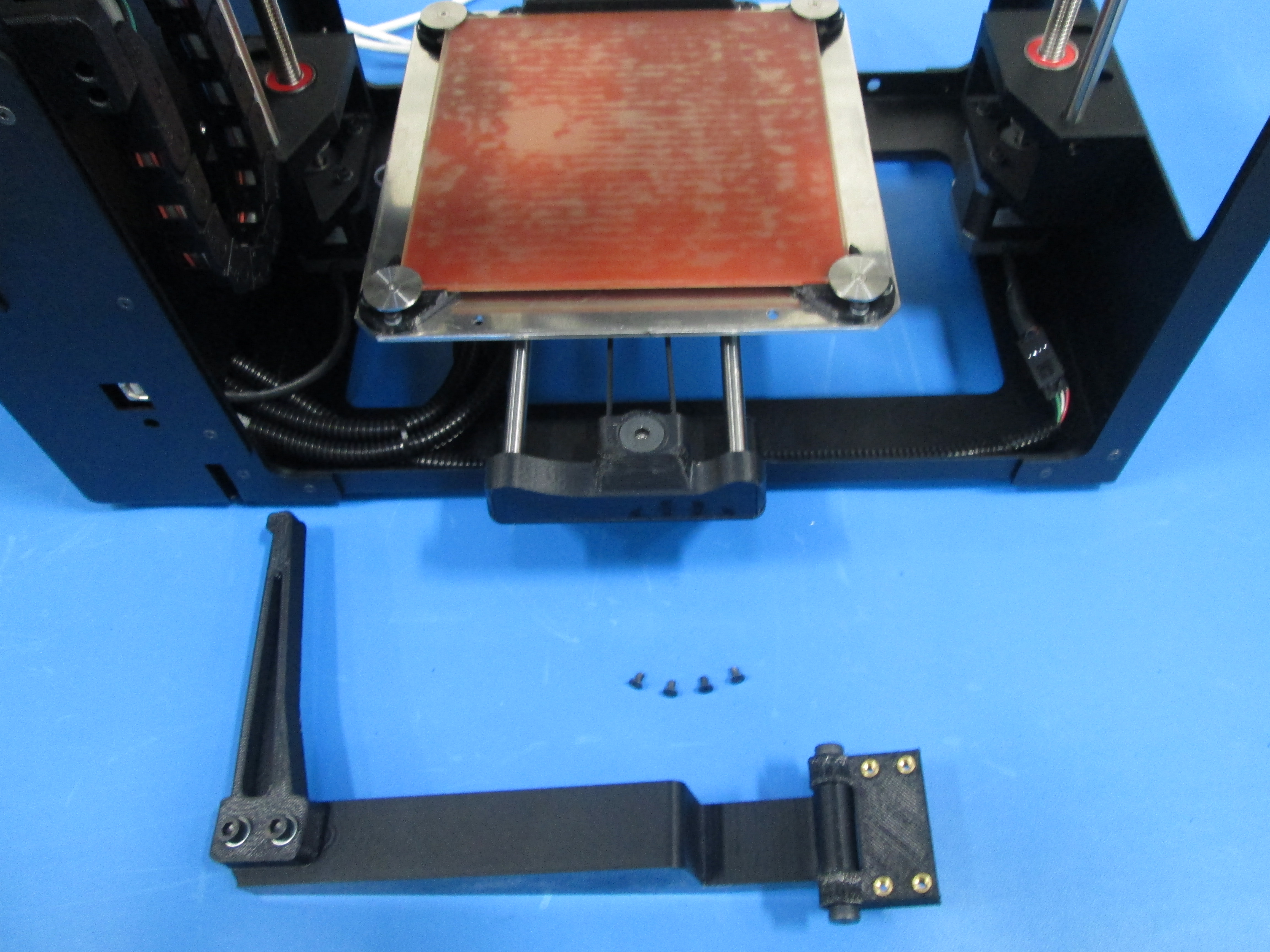
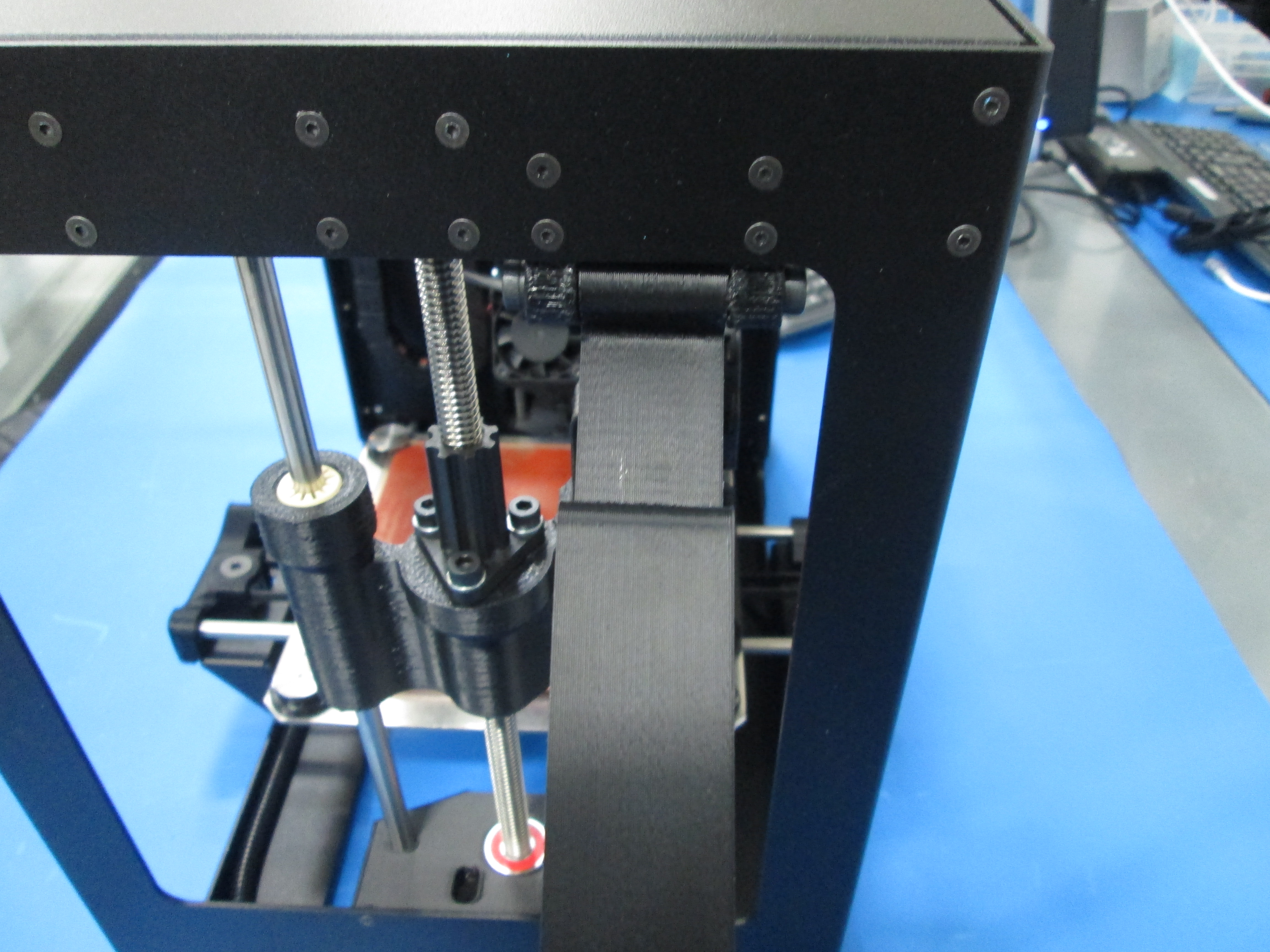
Attach the spool arm to the inside right frame plate using 4x M3x6 flat head screws as shown.