Open HardwareAssembly Instructions
Guides for installation and assembly of the LulzBot line of products made by FAME 3D LLC.
Guides for installation and assembly of the LulzBot line of products made by FAME 3D LLC.
Components Required
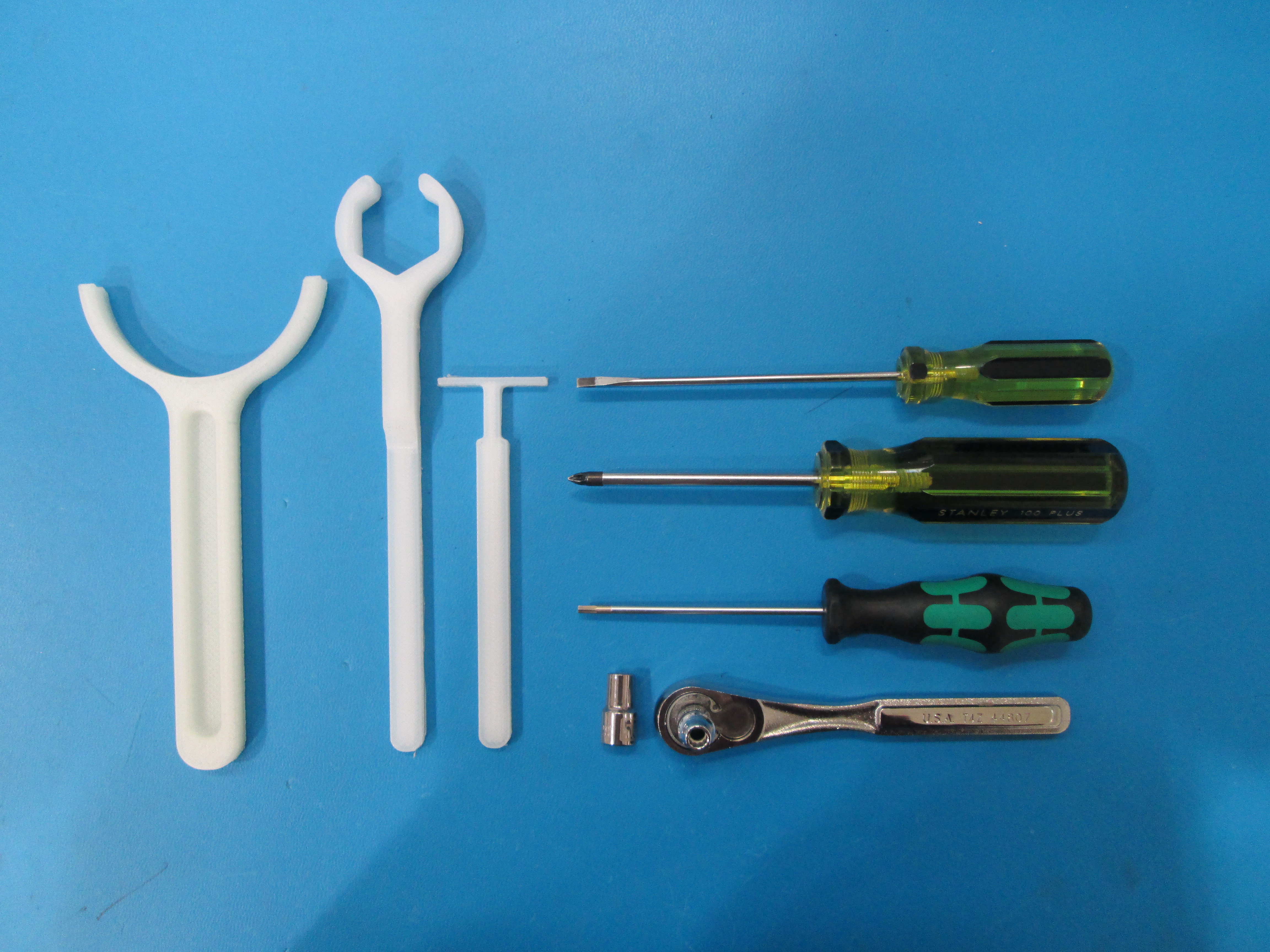
Tools Required
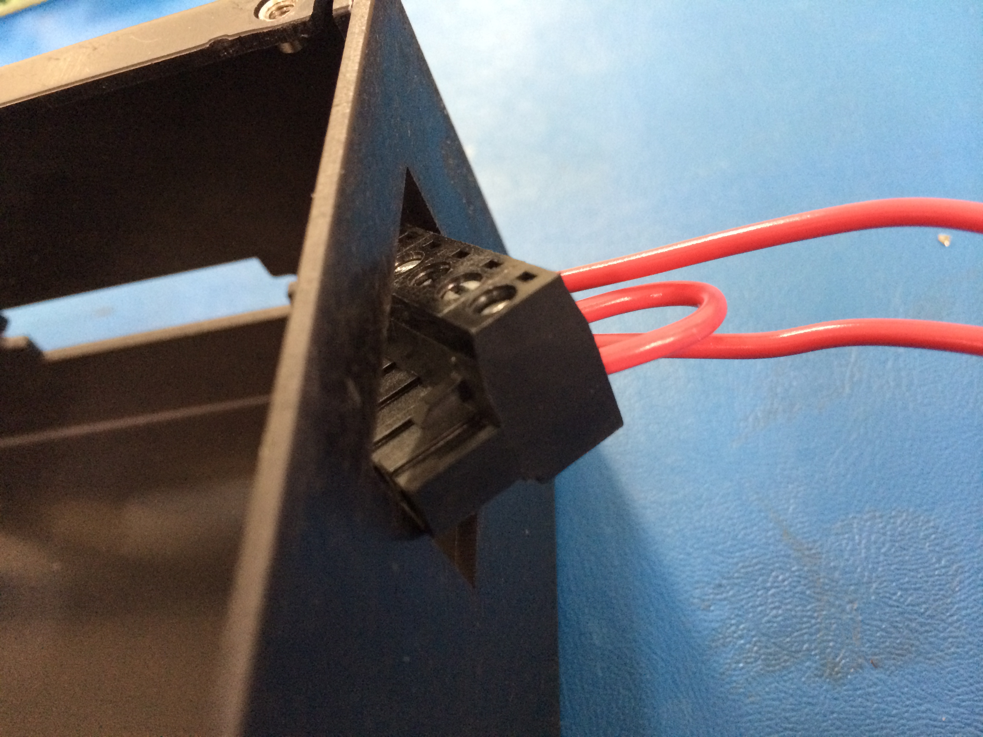
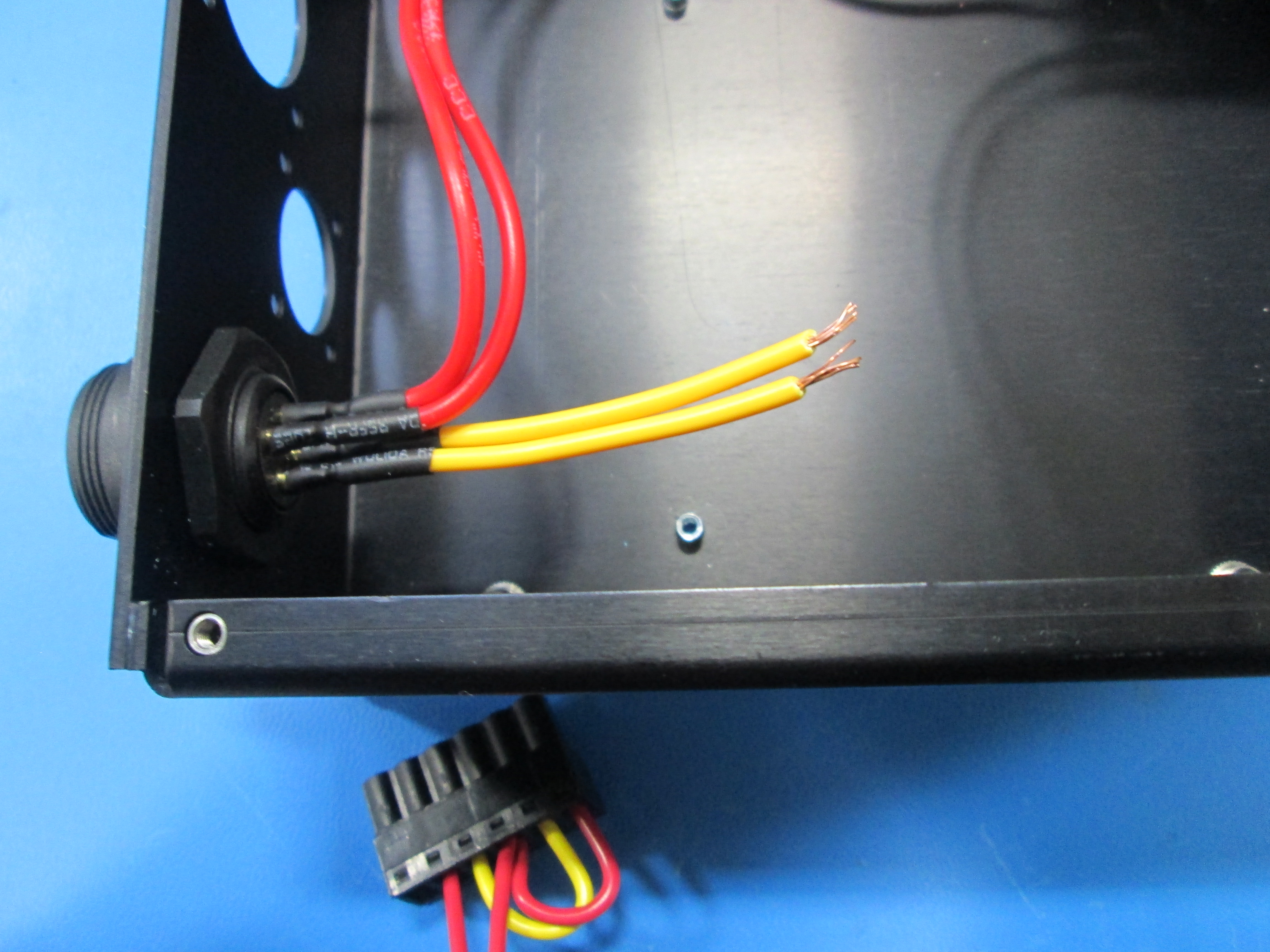
Pull the power harness through the rocker switch hole with 6POS terminal block (TB) going through the CB (Control Box) first as shown
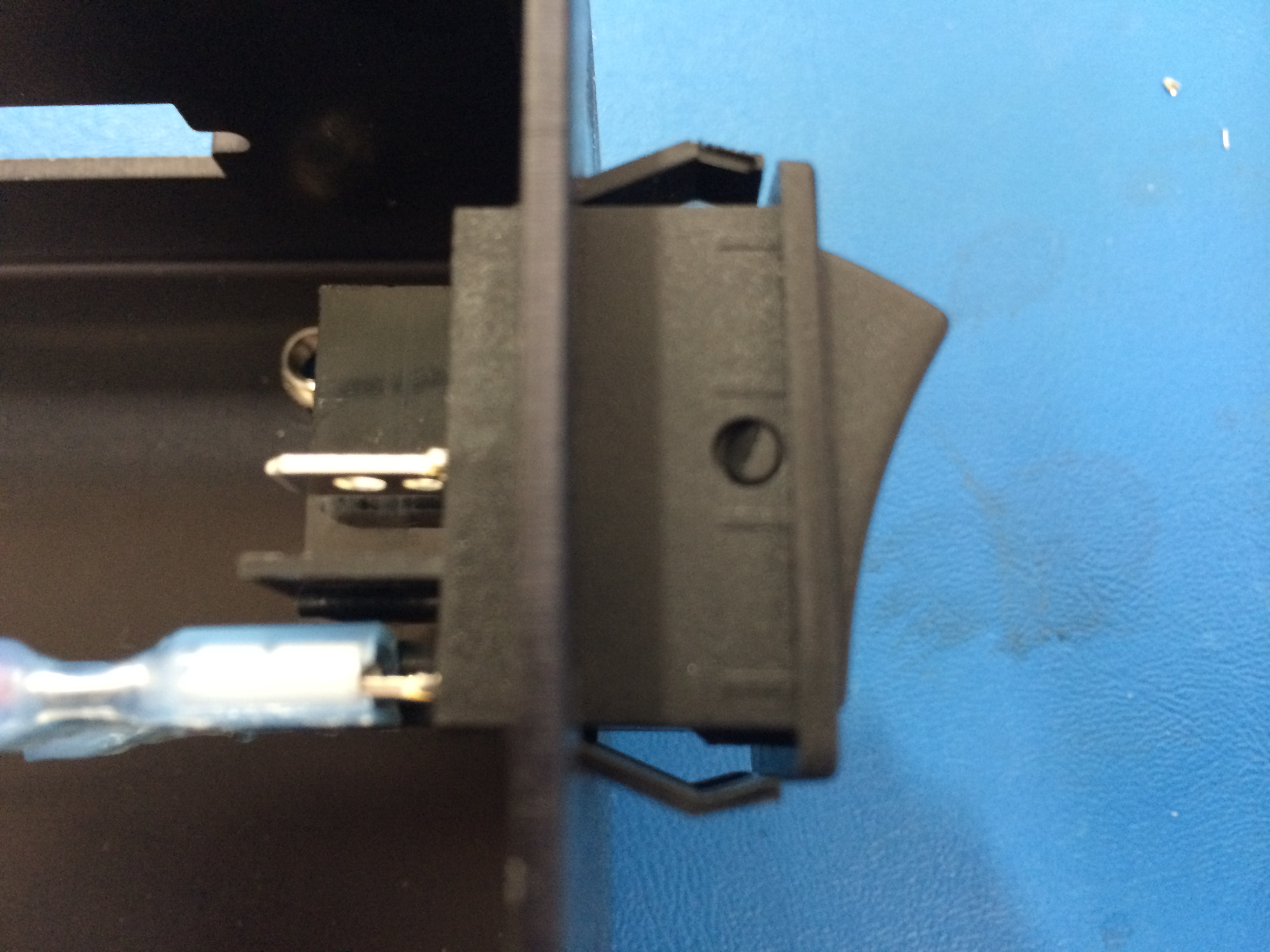
Connect the two red wires to the rocker switch, wires are reversible, but must be plugged into the bottom half of the switch as shown
Push the switch all the way in

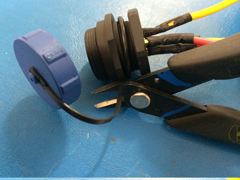
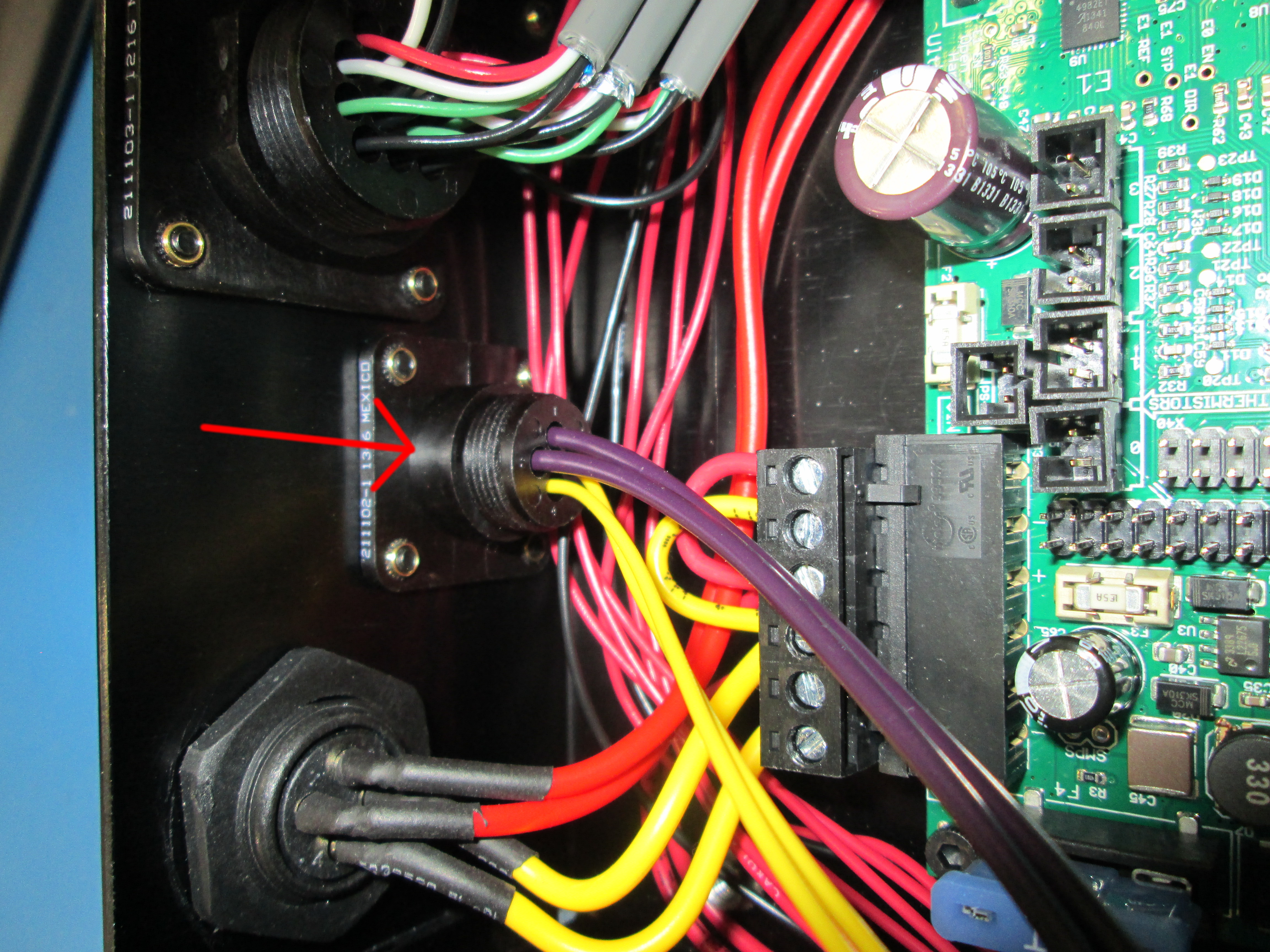
Clip off the cap
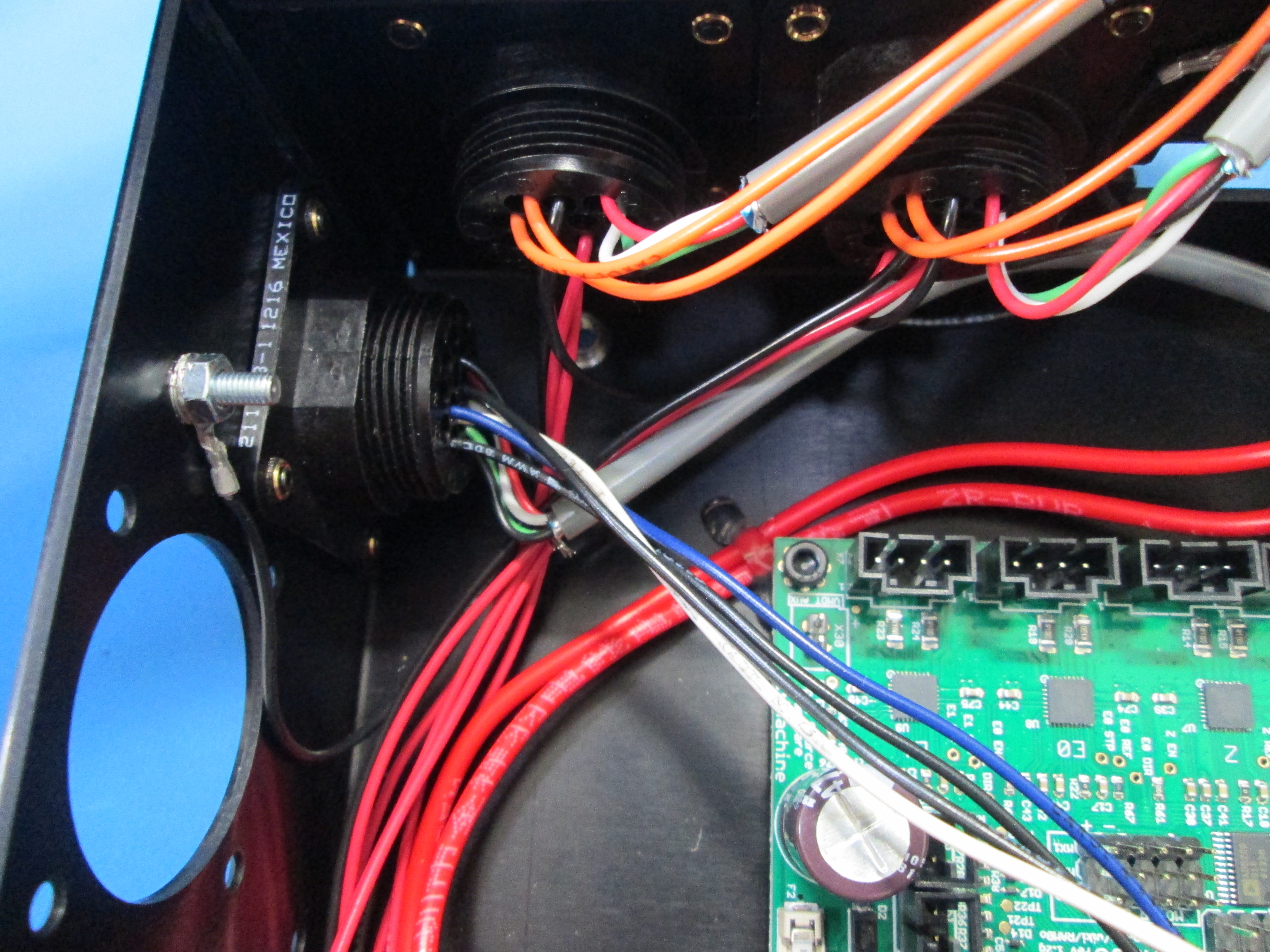
Slide the connector-receptacle tail through the CB first from outside of the bottom hole
Tighten nut by hand first, then by nylon wrench
Pull the 6Pos terminal block outside of the control box to have more room for tightening the nut
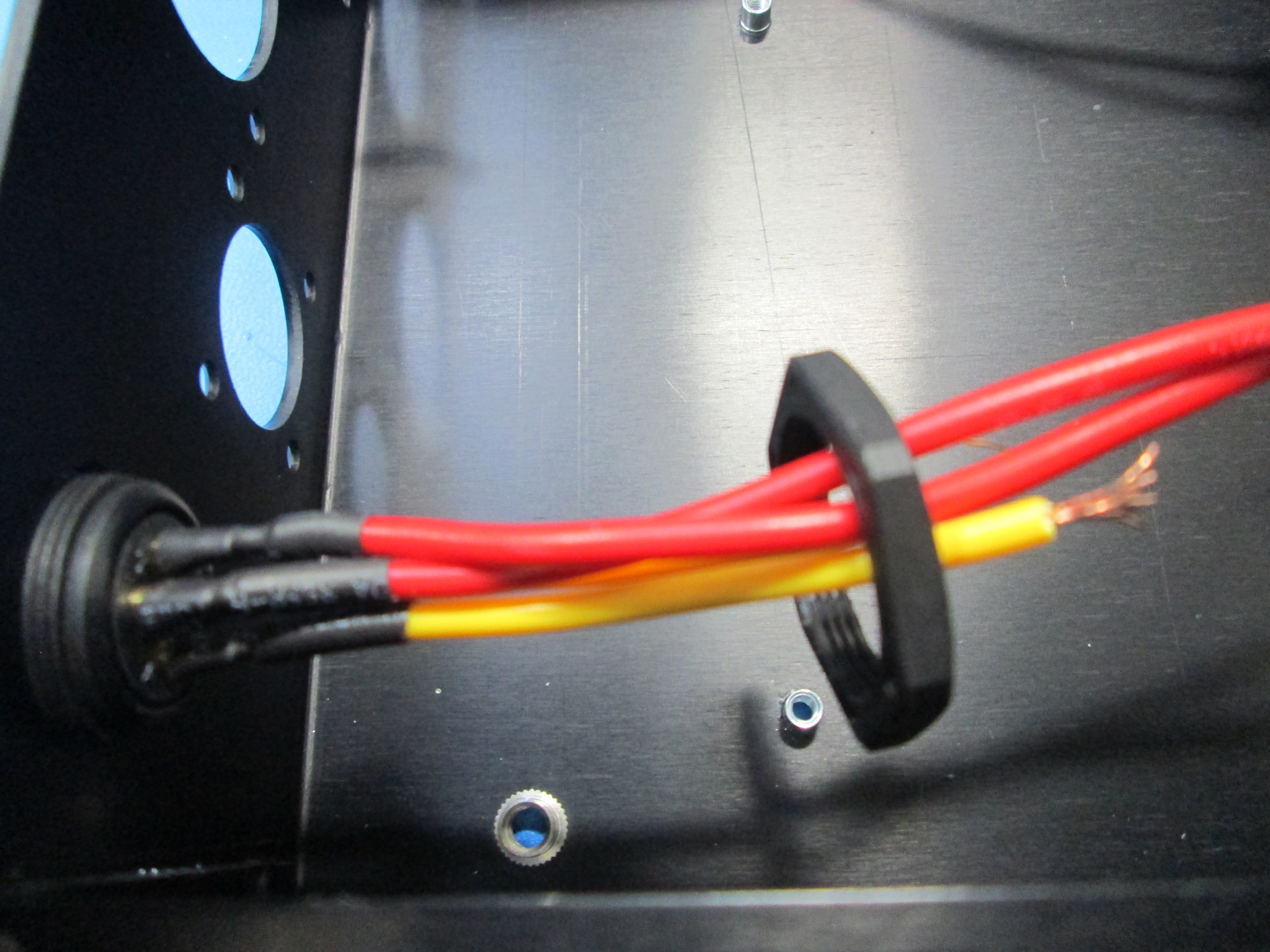

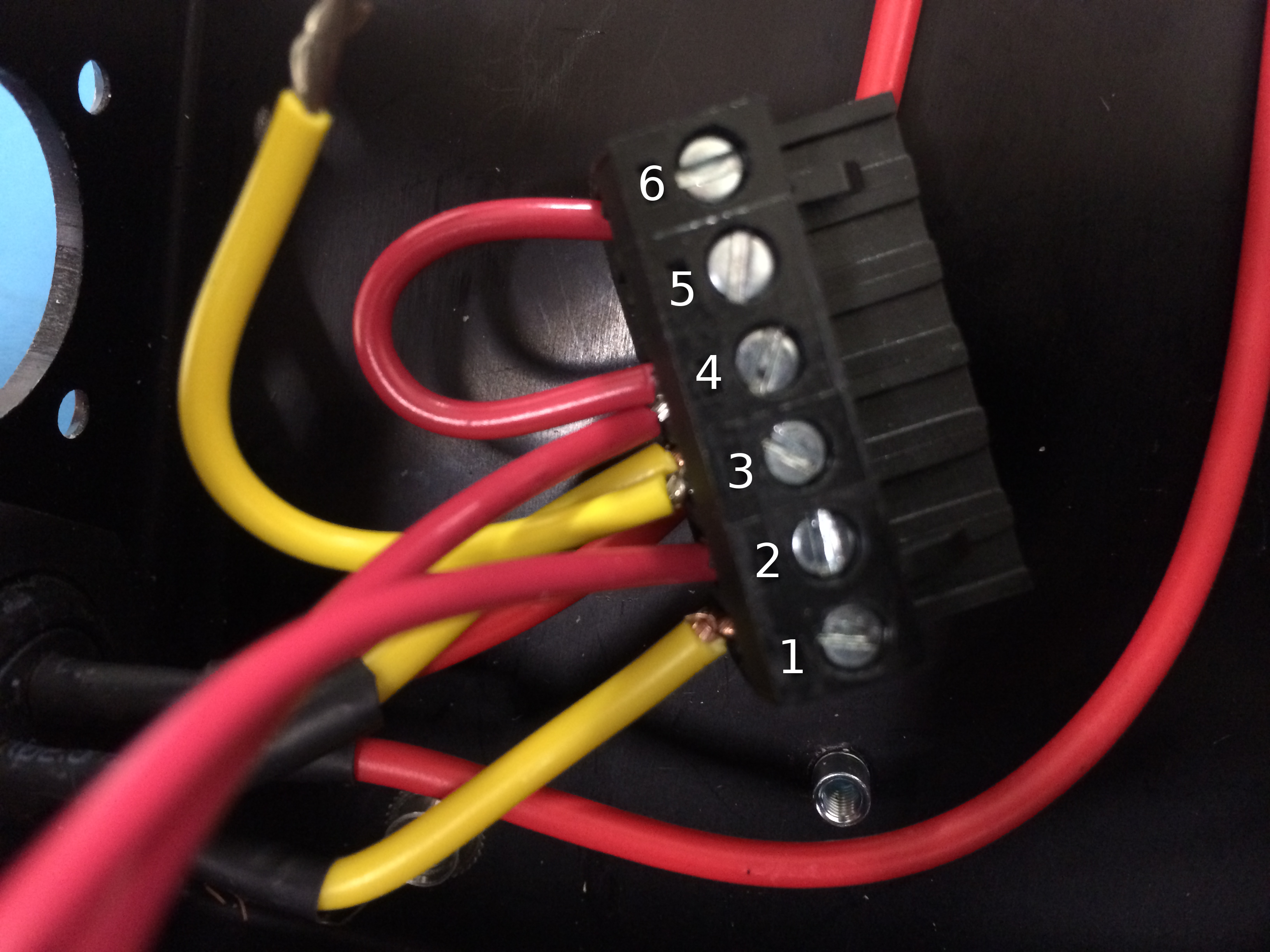
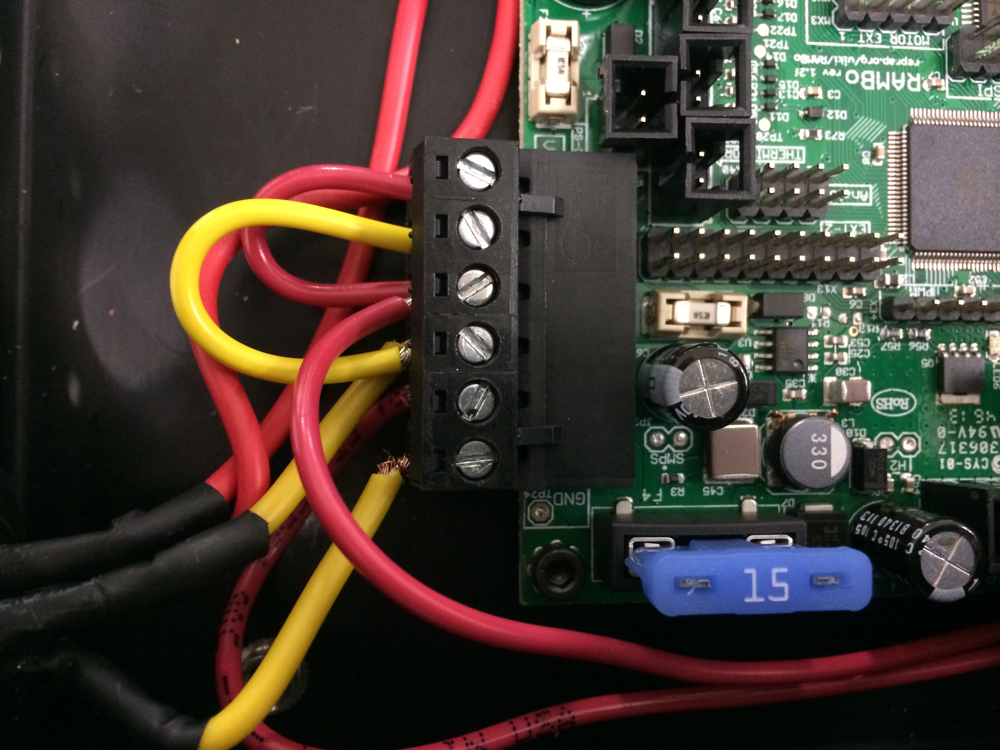
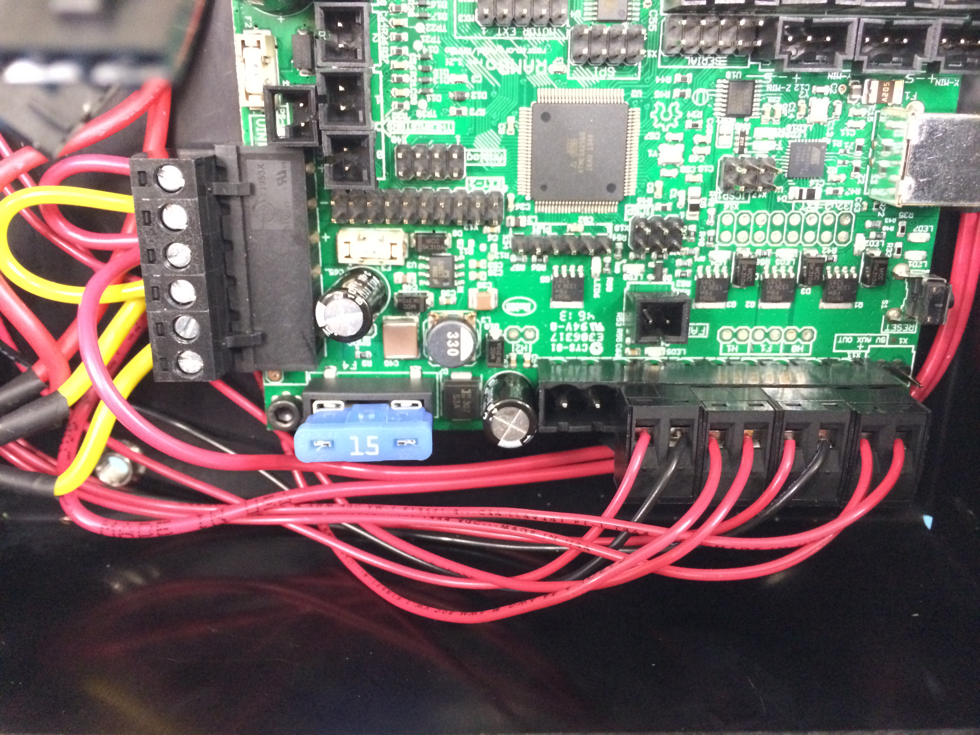
Connect the 2 yellow wires from the receptacle to the TB Pos-1 & 3, then install the 50 mm yellow jumper between Pos 3 & 5
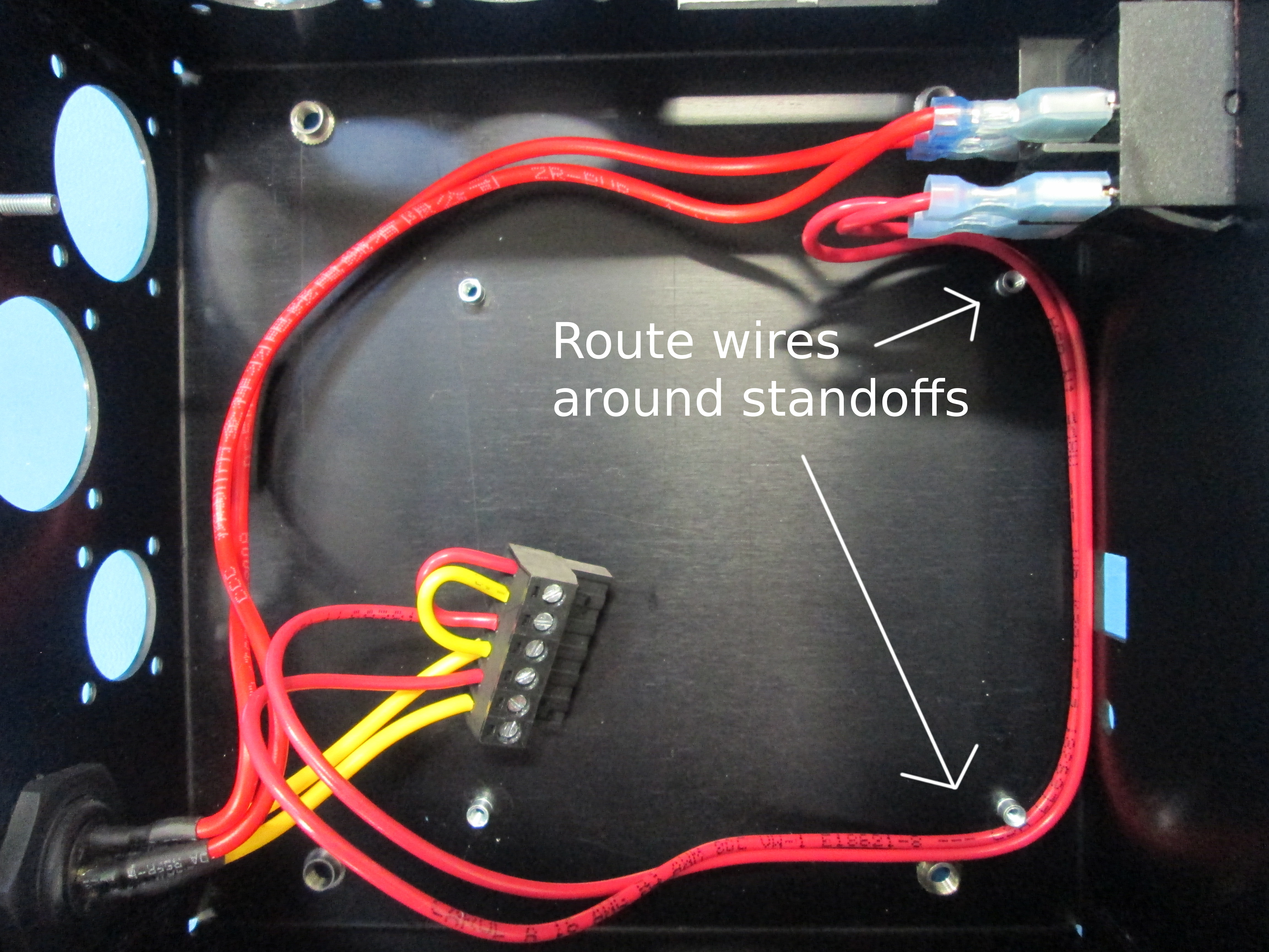
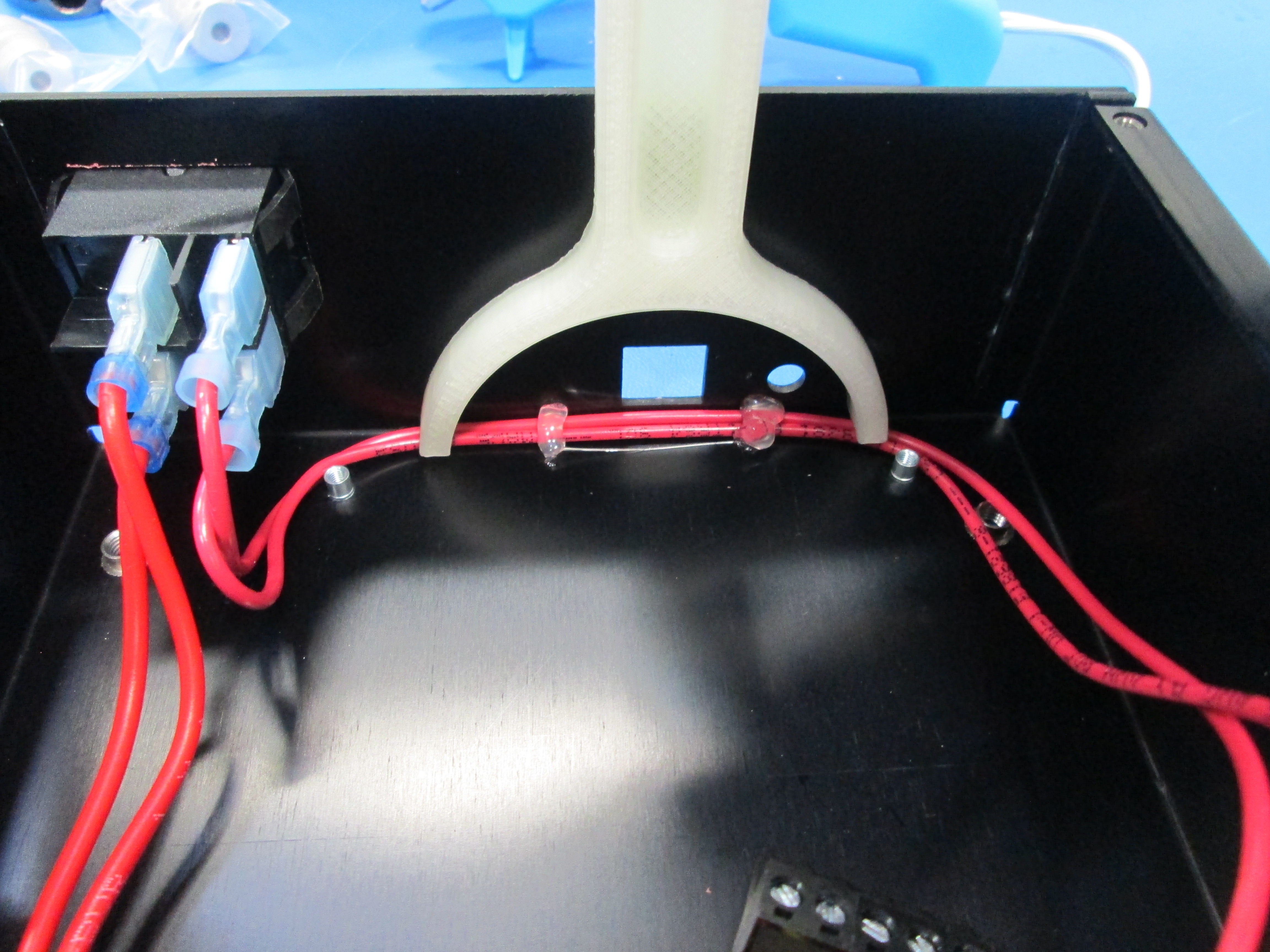
Lay out the wire harnesses with the wires laying flat against the CB as shown
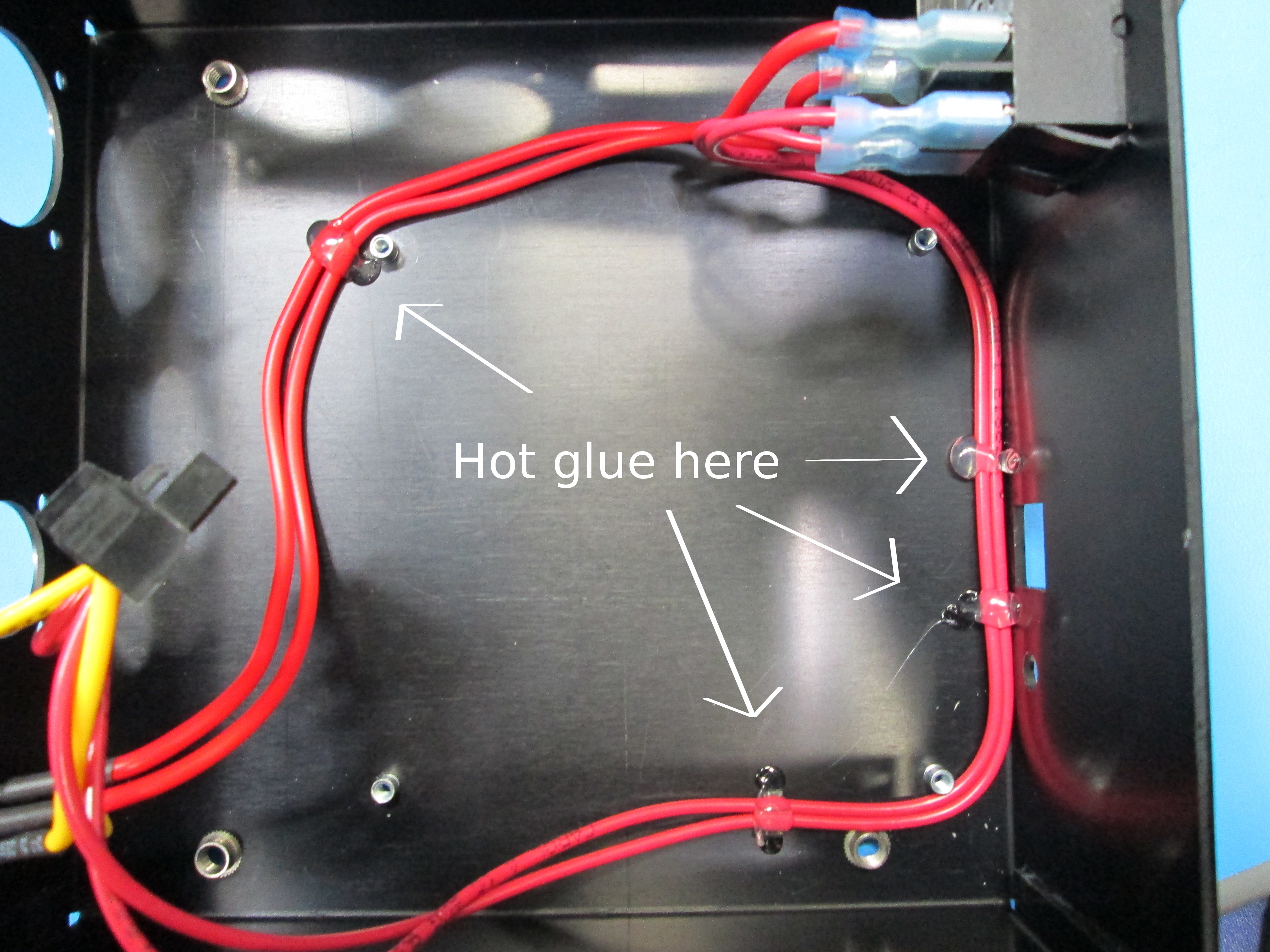
Hot glue in the four locations as shown, if you don't have hot glue, electrical tape can be substituted instead
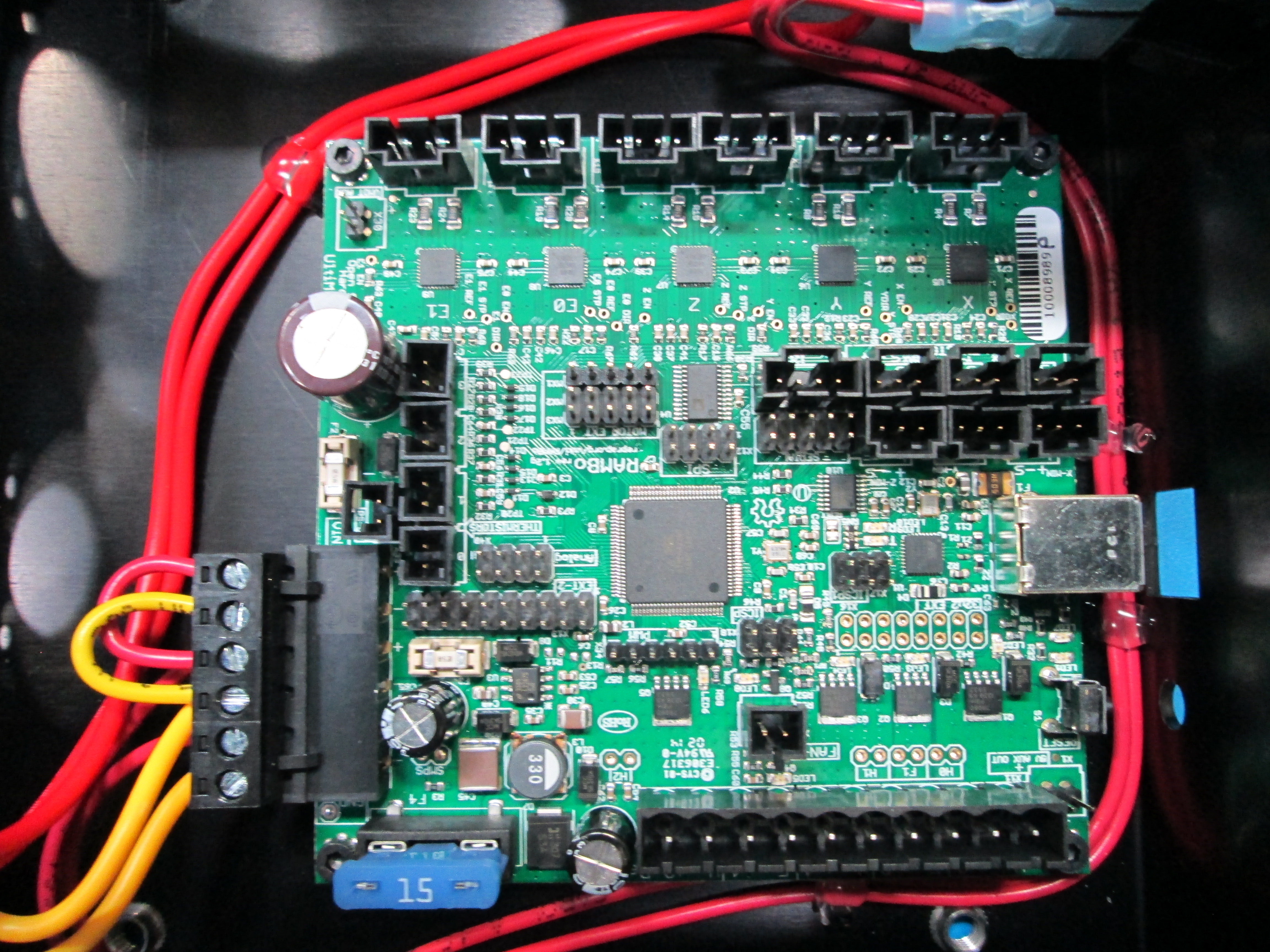
Install Rambo with 4x M3x5 SHCS as shown

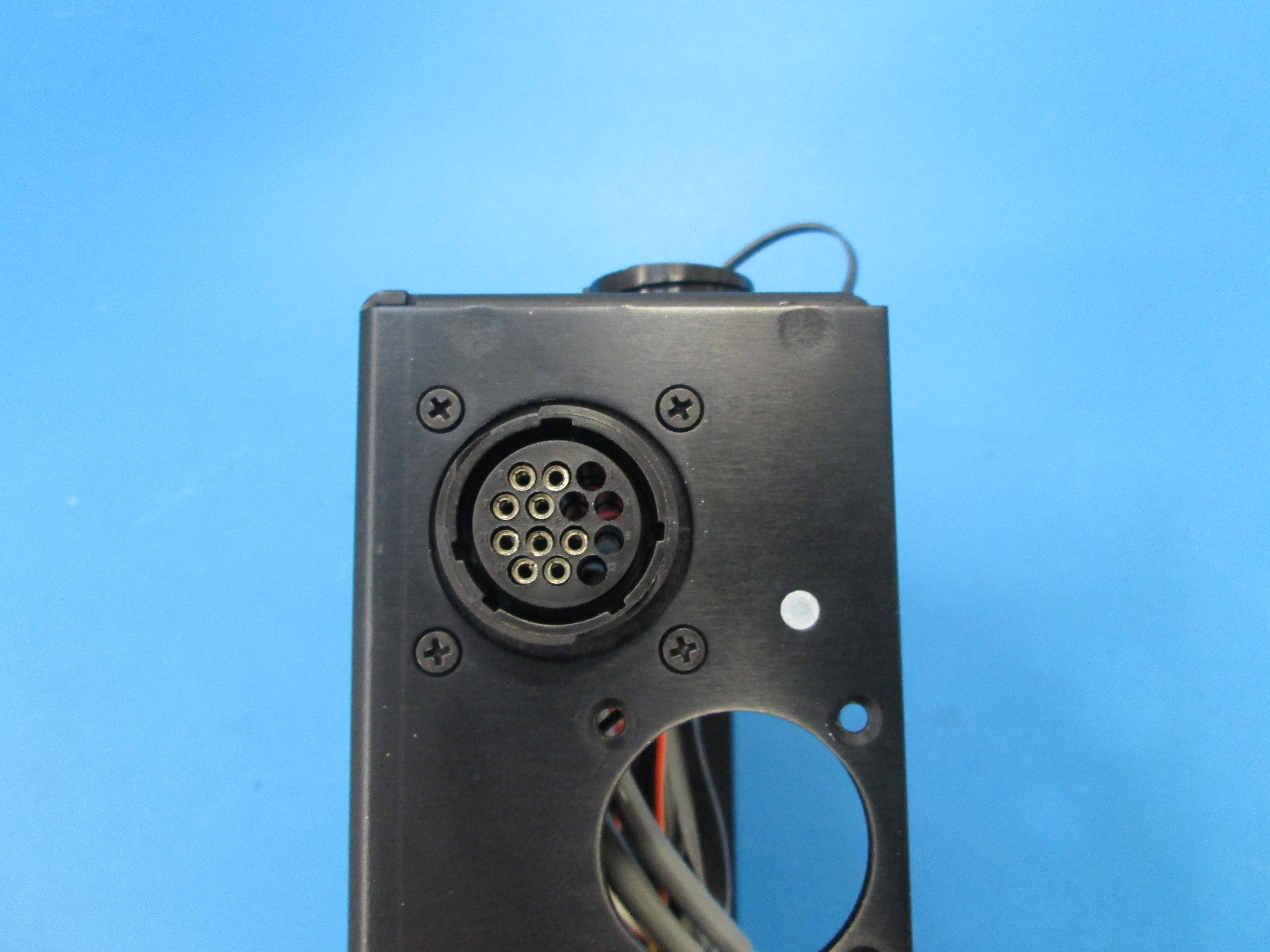
Install Extruder-1 14 Pos connector using far left top hole & 4x 4-40 flat head screws, Pin2 with black ground wire should be facing front(you)
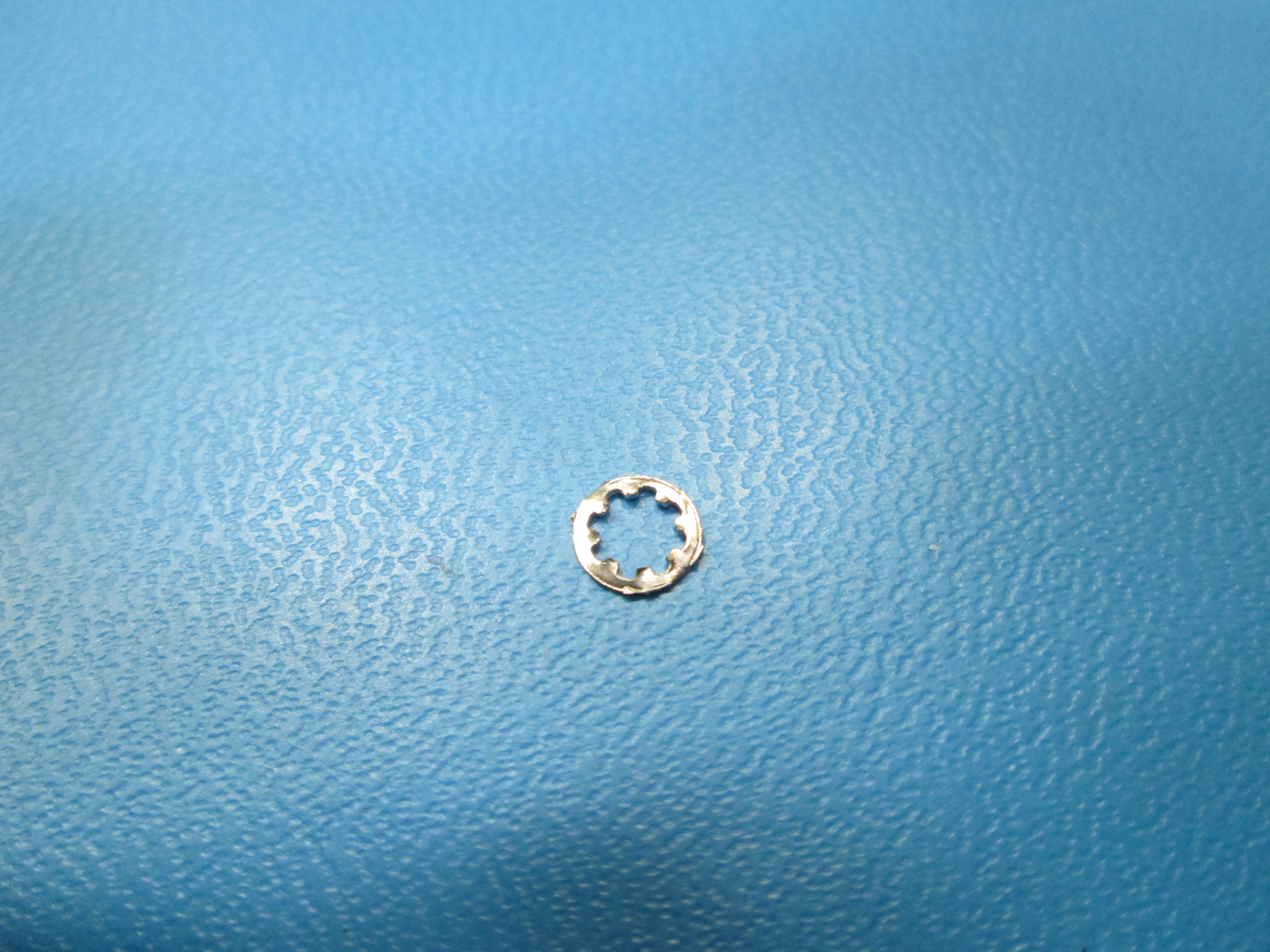
Install M3 Star washer onto ground post
Route black ground wire and hook to ground post as shown
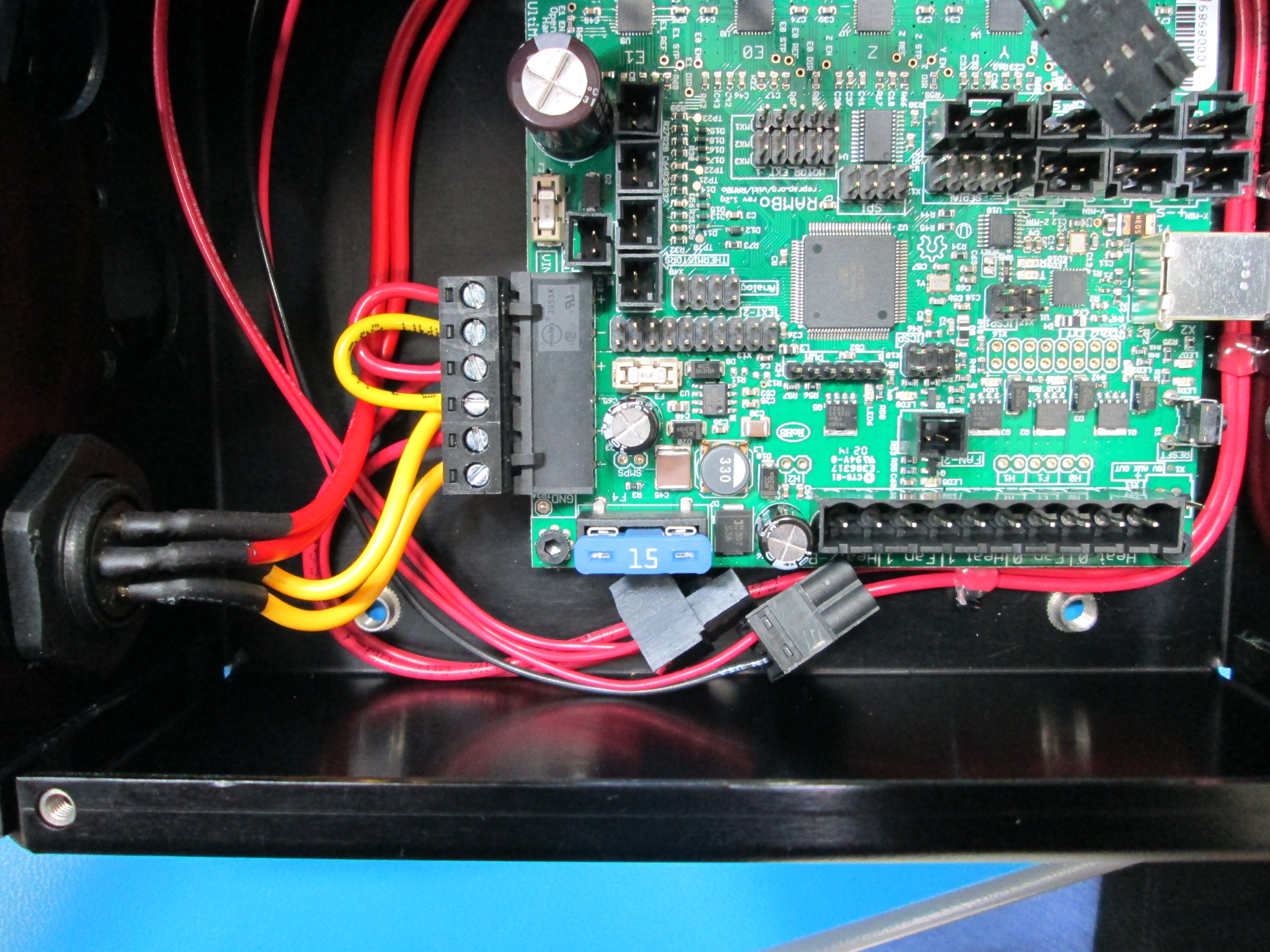
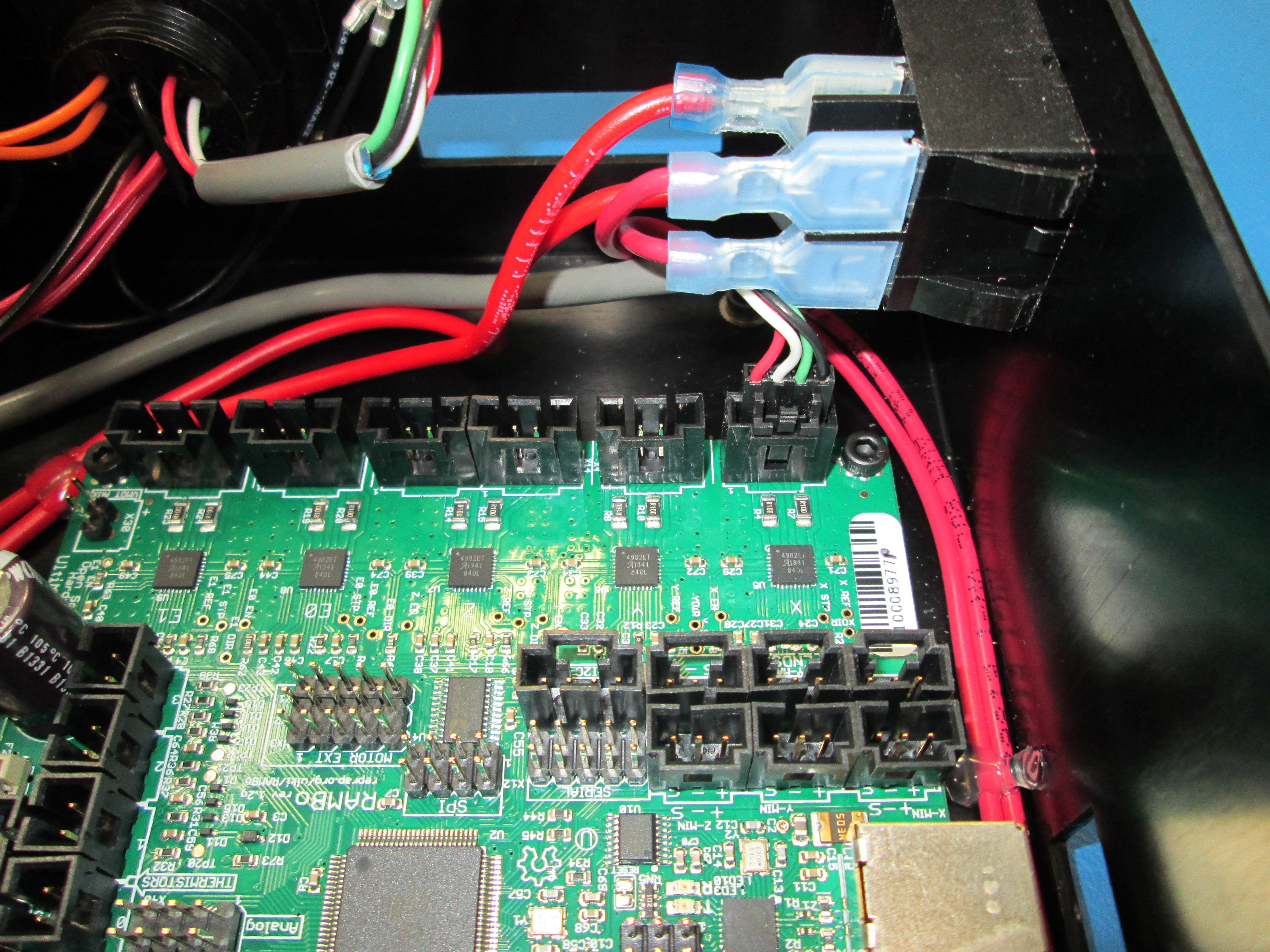
Route the 2-red extruder heat wires and the red/black fan wire under the red/yellow power harness as shown
Connect the 2 red extruder heat wires to the Extruder Heat-0 (right most slot) TB, and Red/Black fan wire to Extruder Fan-0 slot
Leave the orange thermistor and 4 wire extruder motor wire dangling outside the box

Install Extruder-2 connector using the other top hole, Pin 2 with the black ground wire should be facing you. At the same time mount the Dust Cover to one of the 4 flat head screws as shown, then screw on dust cap
Route ground wire to ground post
Then use M3 nut to secure the ground wires to the ground lug
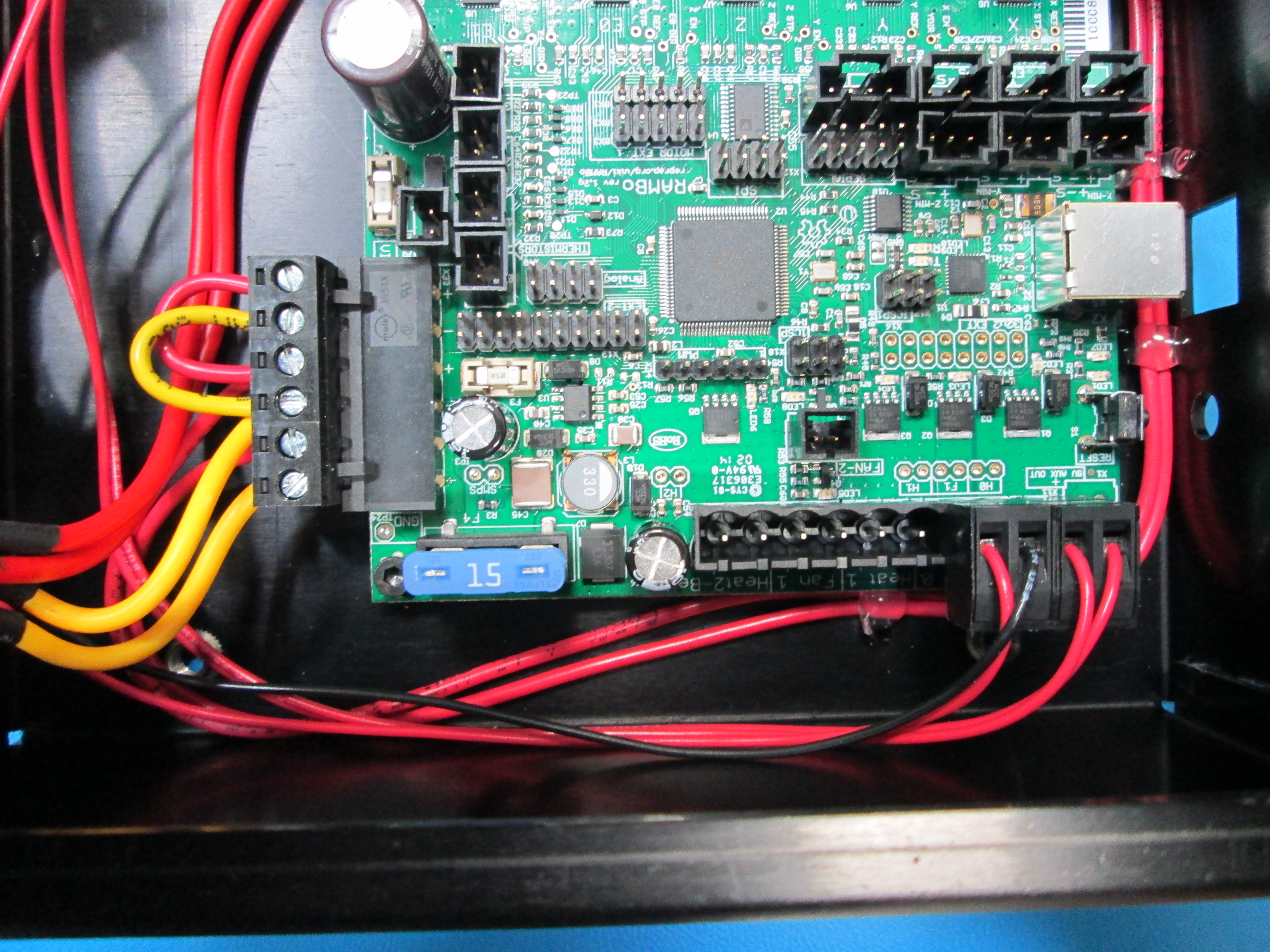
Route 2-Red extruder heat wires and Red/Black fan wires under power harness
Connect 2-Red extruder heat wire to the Extruder Heat-1 TB, and Red/Black fan wire to Extruder Fan-1 slot as shown below

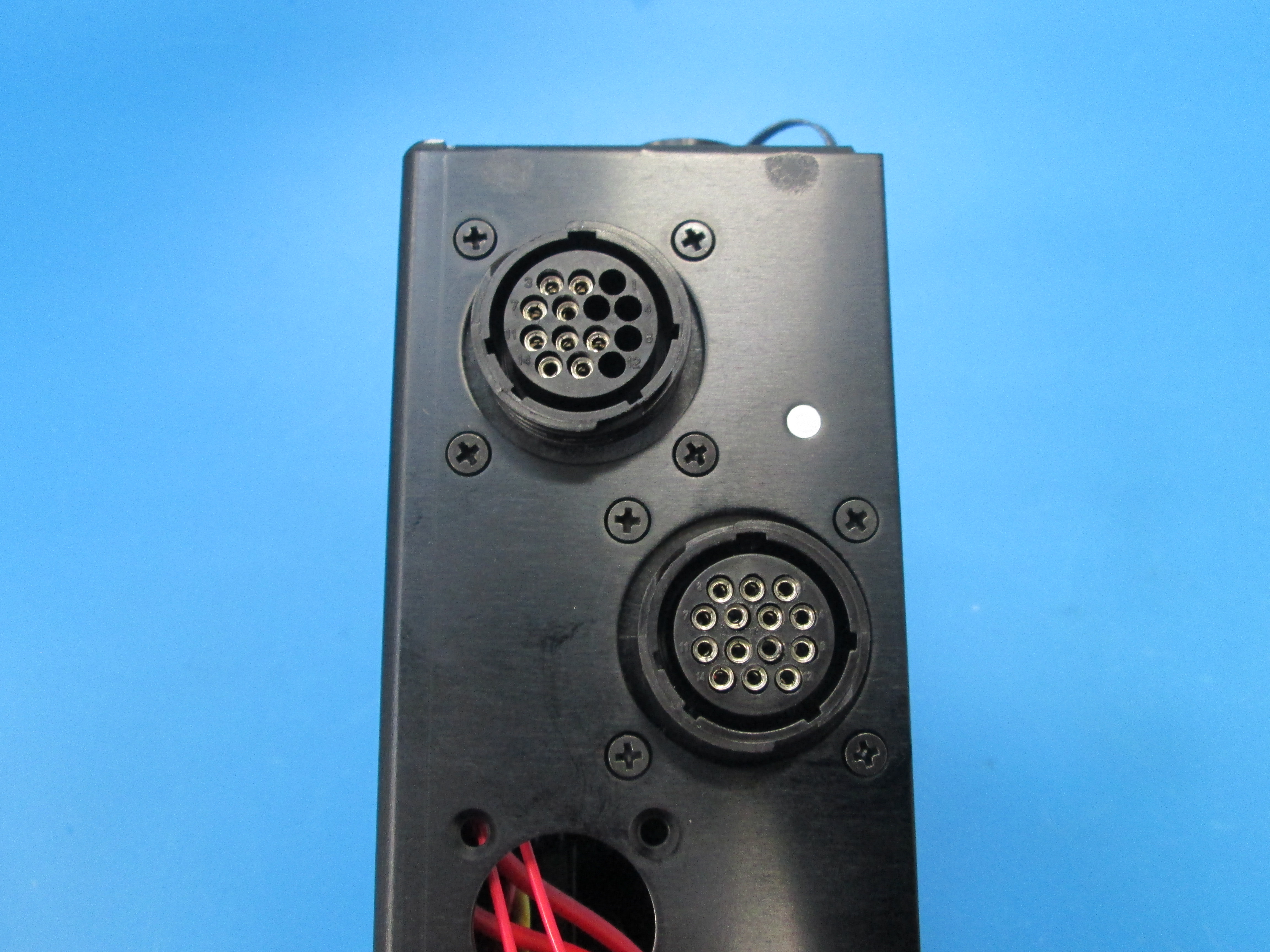
Install the Extruder-XZ 14Pos connector into the left side top hole using 4x 4-40 screws, the Pin 2 with black ground wire will be facing the top as shown
Install M3 Star washer onto ground post
Route the black ground wire and attach to ground post and secure with M3 nut as shown
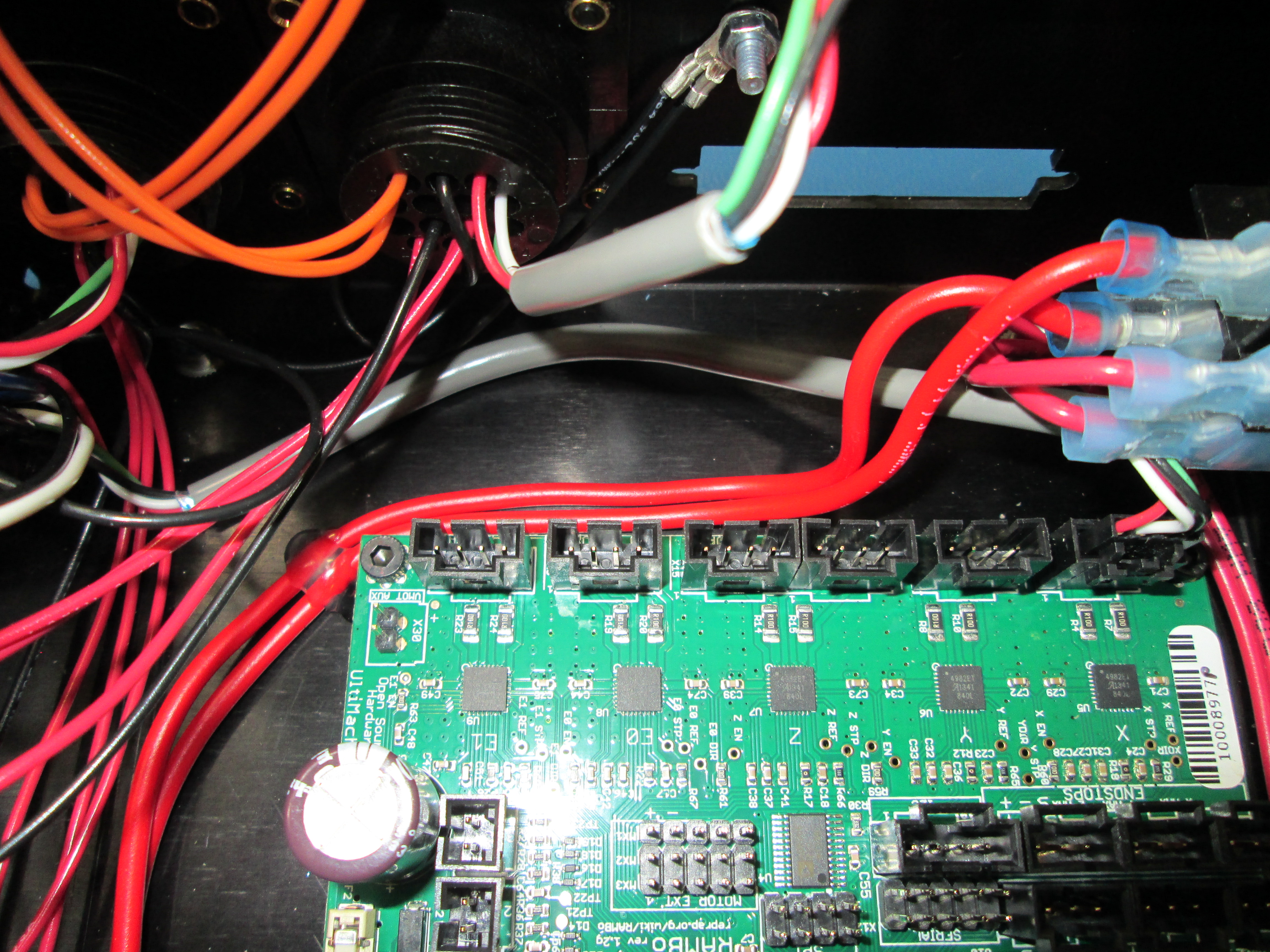
Route the X Motor cable under the Extruder 2 harness to RAMBO X Motor connector
Pull the motor and switch wires out of the way for now
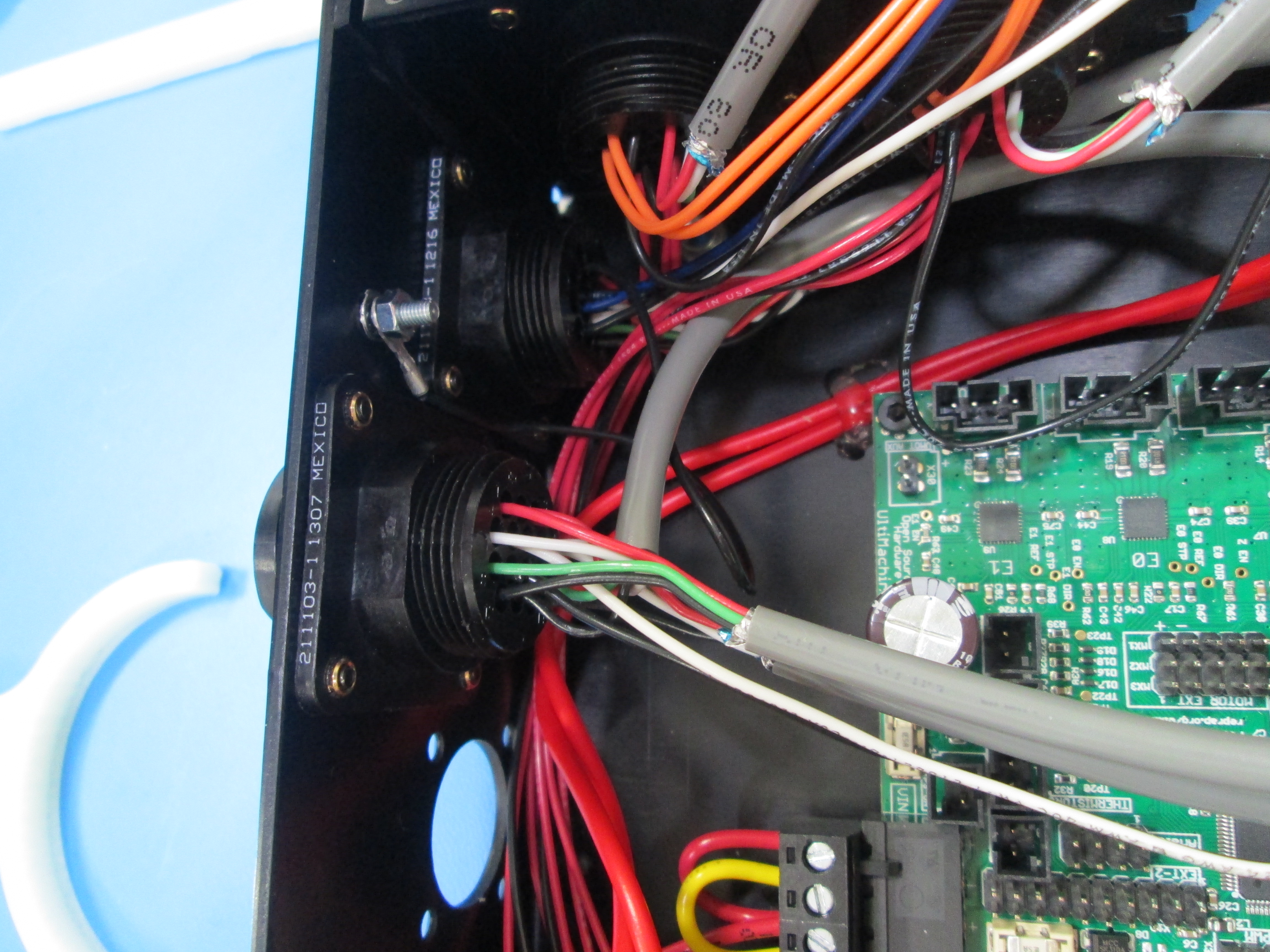
Install the CB YZ 14Pos connector using the left side 2nd from top hole and 4x 4-40 flat head screws; make sure the Pos 2 wire is facing the top, from the outside, the large notch in 14Pos connector will be facing up as shown
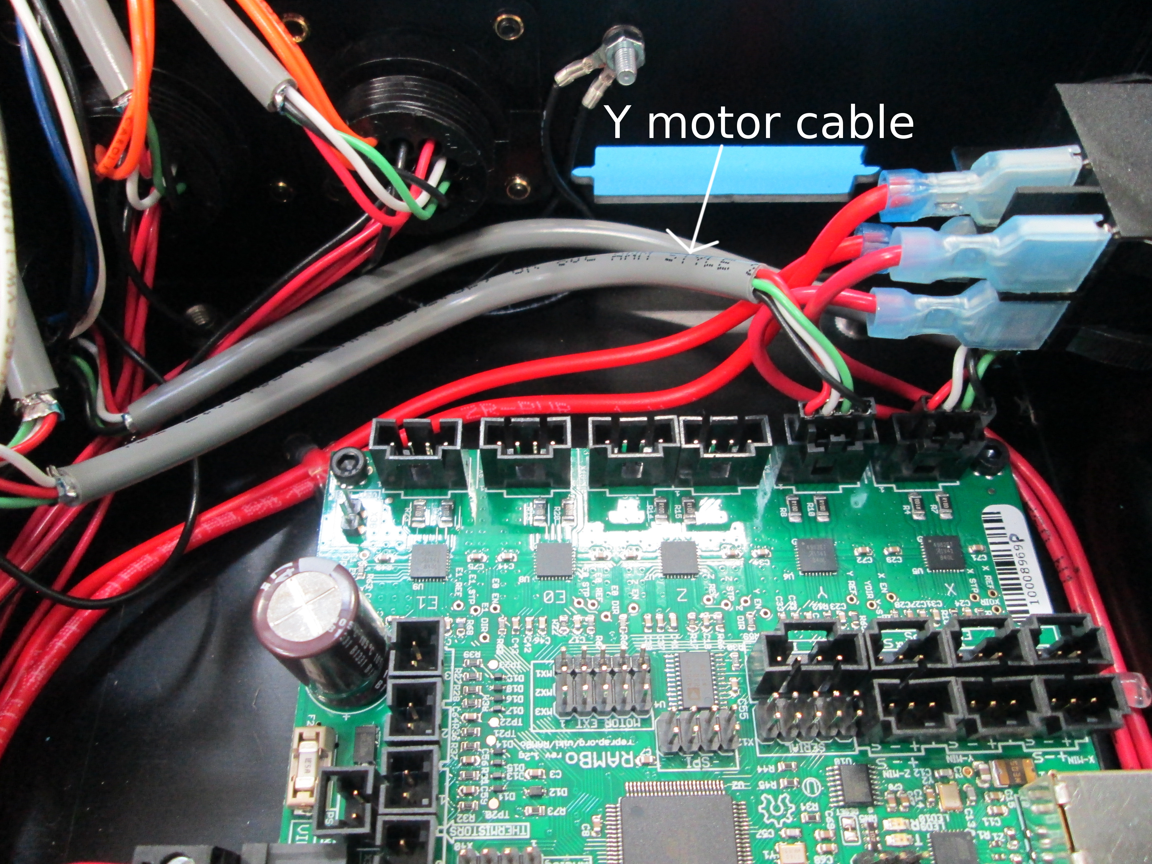
Connect Y-motor cable(Y motor cable is the grey middle cable and also the longest) to Y Motor male connector housing on Rambo as shown
Leave other cables out of the way for now
Continue working with the YZ connector
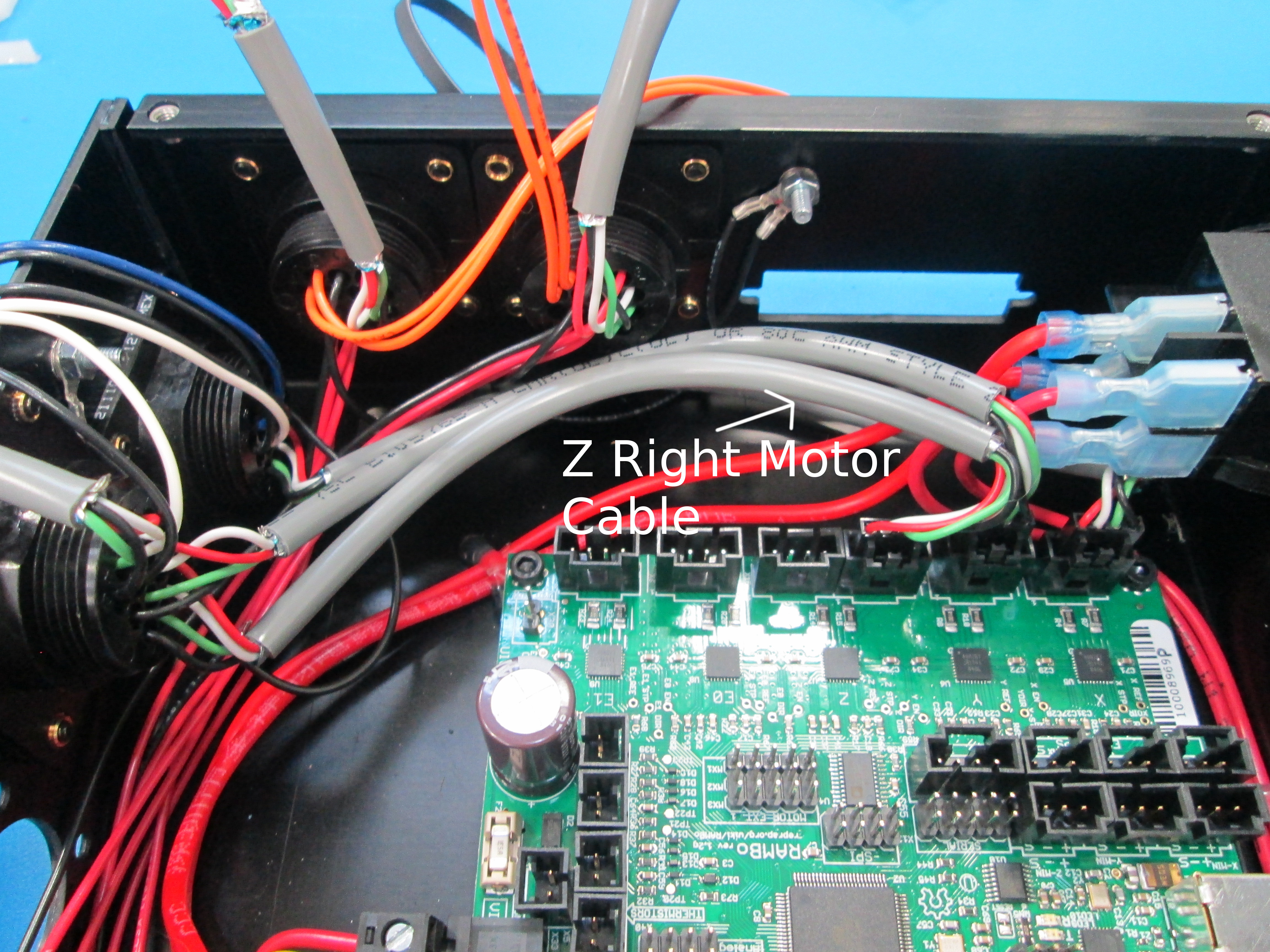
Connect Z-Right motor cable(which is the lowest 4 pos cable) to “Z Motor 1” male connector housing on Rambo as shown
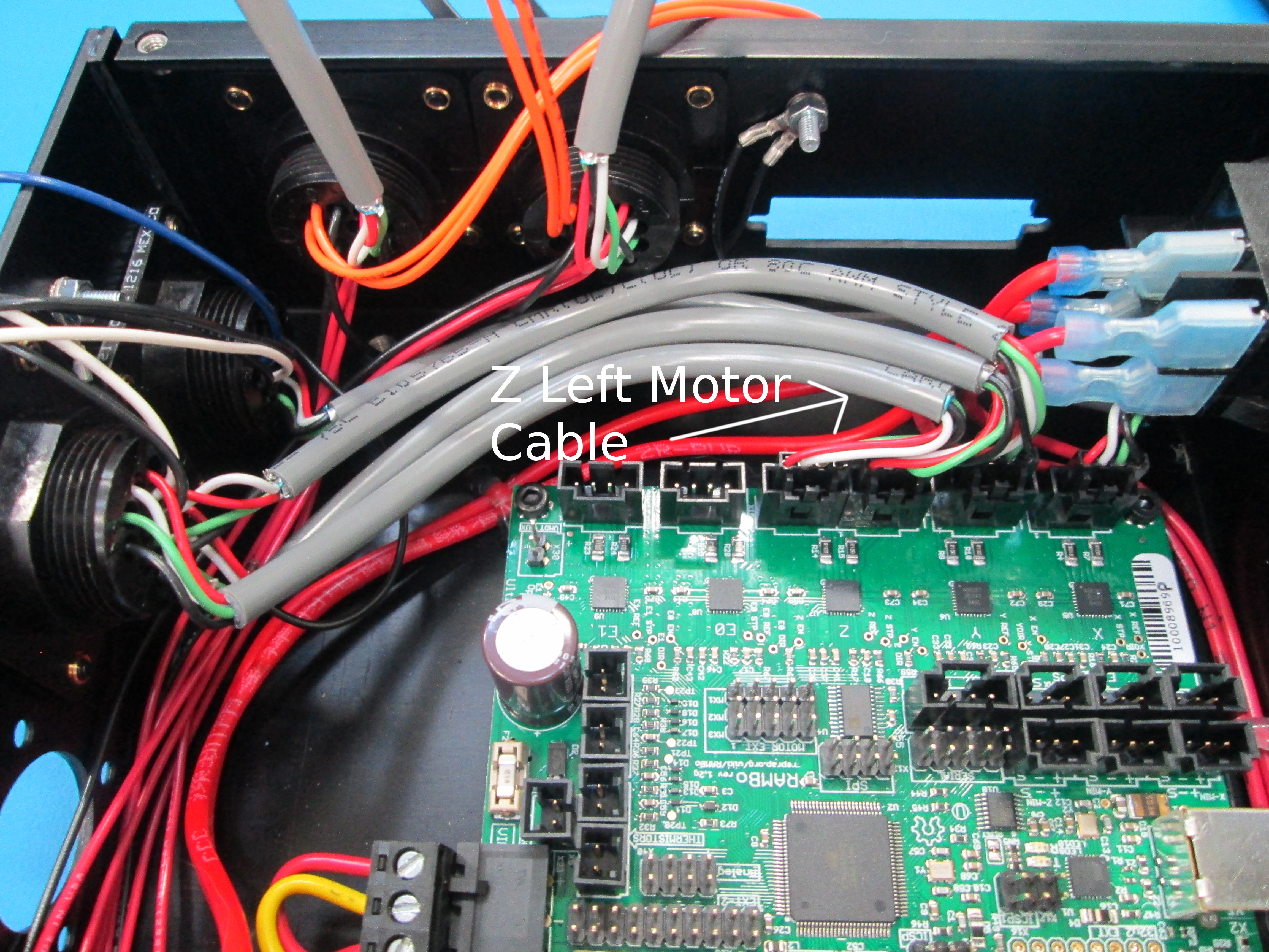
Connect Z-Left motor(which is the highest 4 pos cable) cable to “Z Motor 2” male connector housing on Rambo as shown
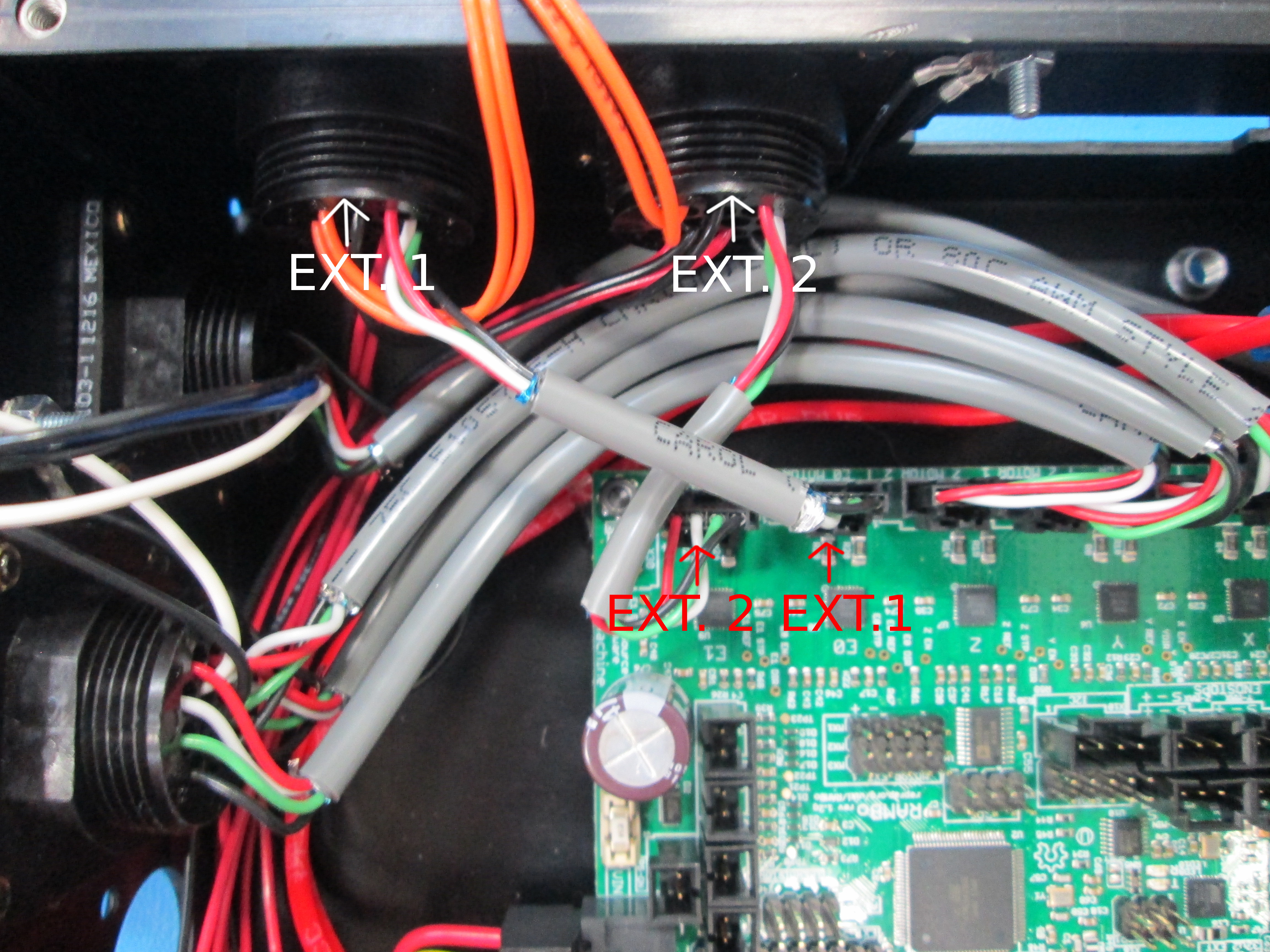
Connect Extruder-2 motor cable to Rambo “E1 Motor” connector
Connect Extruder-1 motor cable to Rambo “E0 Motor” connector (over the top of Extruder-2 motor cable) as shown
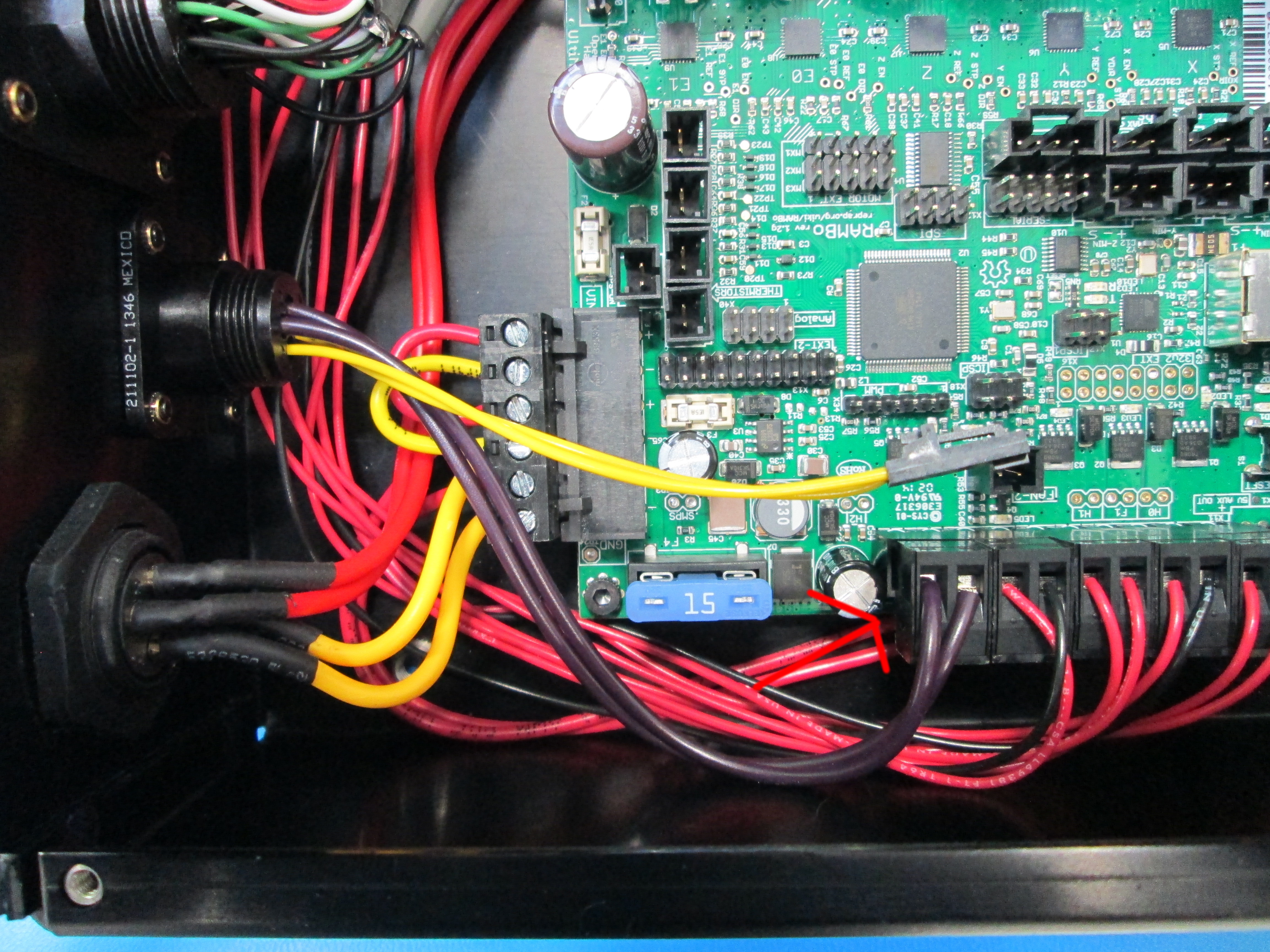
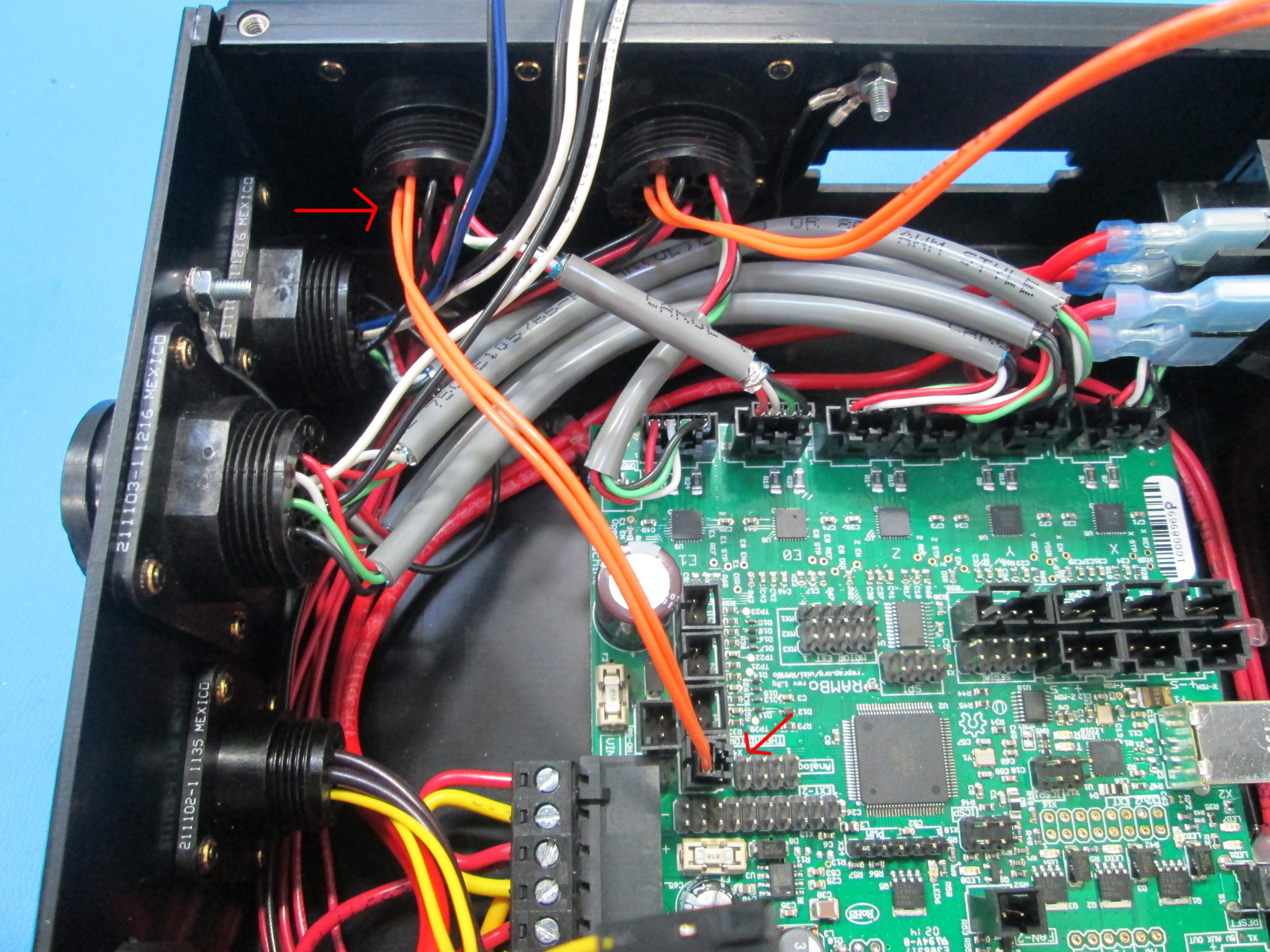
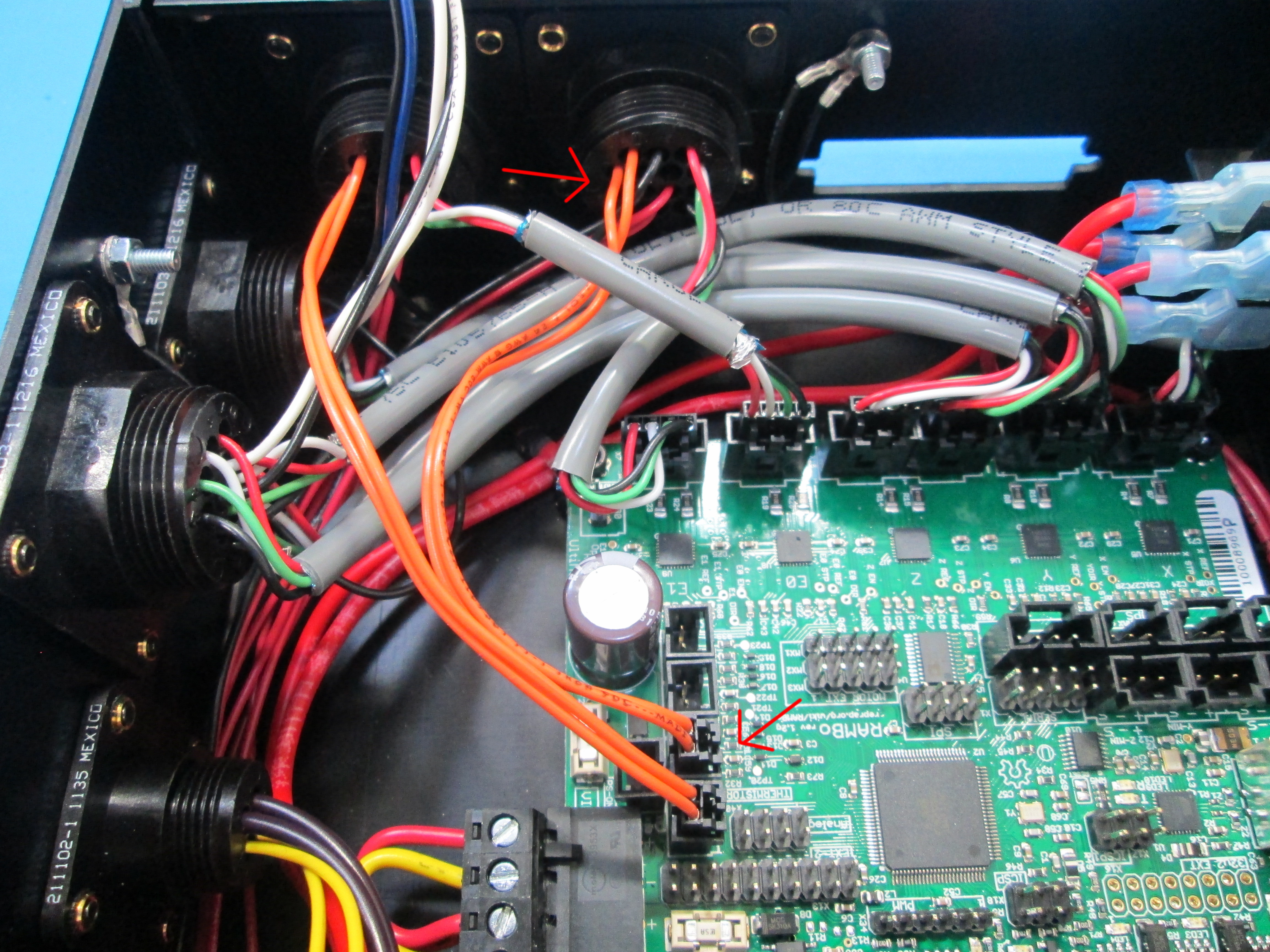
Connect Extruder-1 thermistor connector (orange wires) to RAMBO male housing – bottom position as shown
Similarly connect Extruder-2 thermistor connector (orange wires) to 2nd slot from the bottom
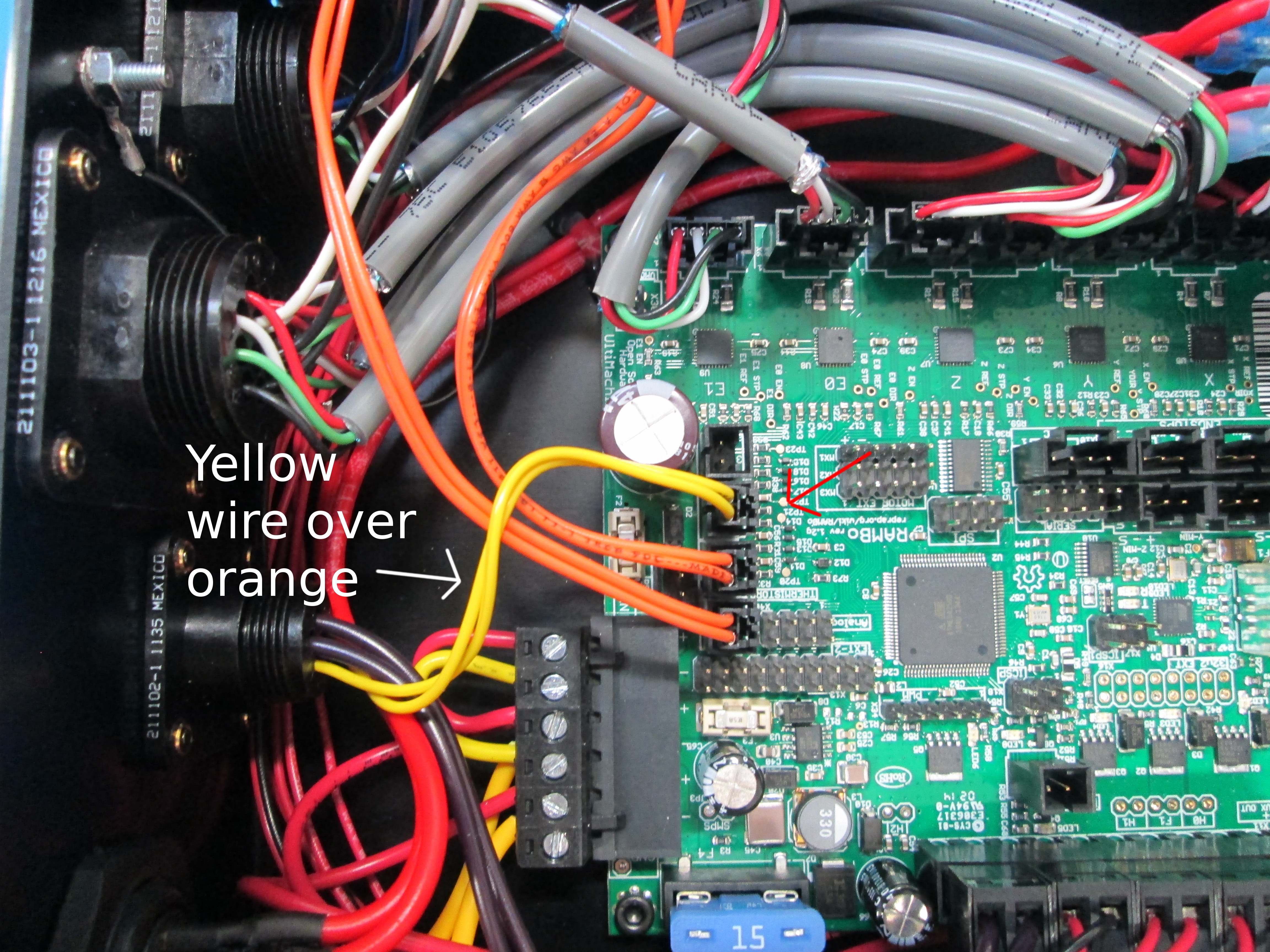
Connect the heat bed thermistor connector (with yellow wires) to RAMBO 3rd slot from the bottom as shown, make sure the yellow wires go over the top of the orange wires
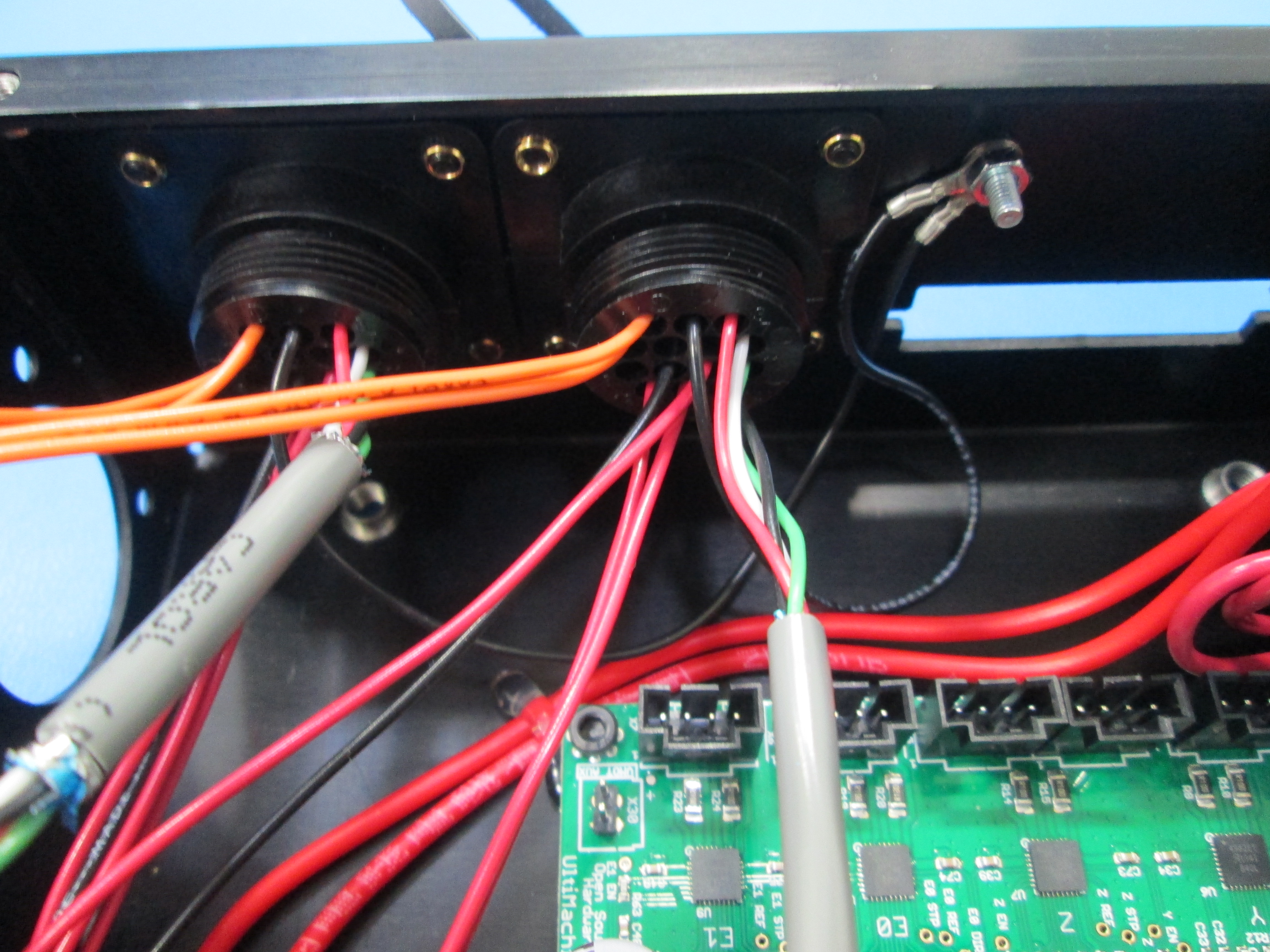
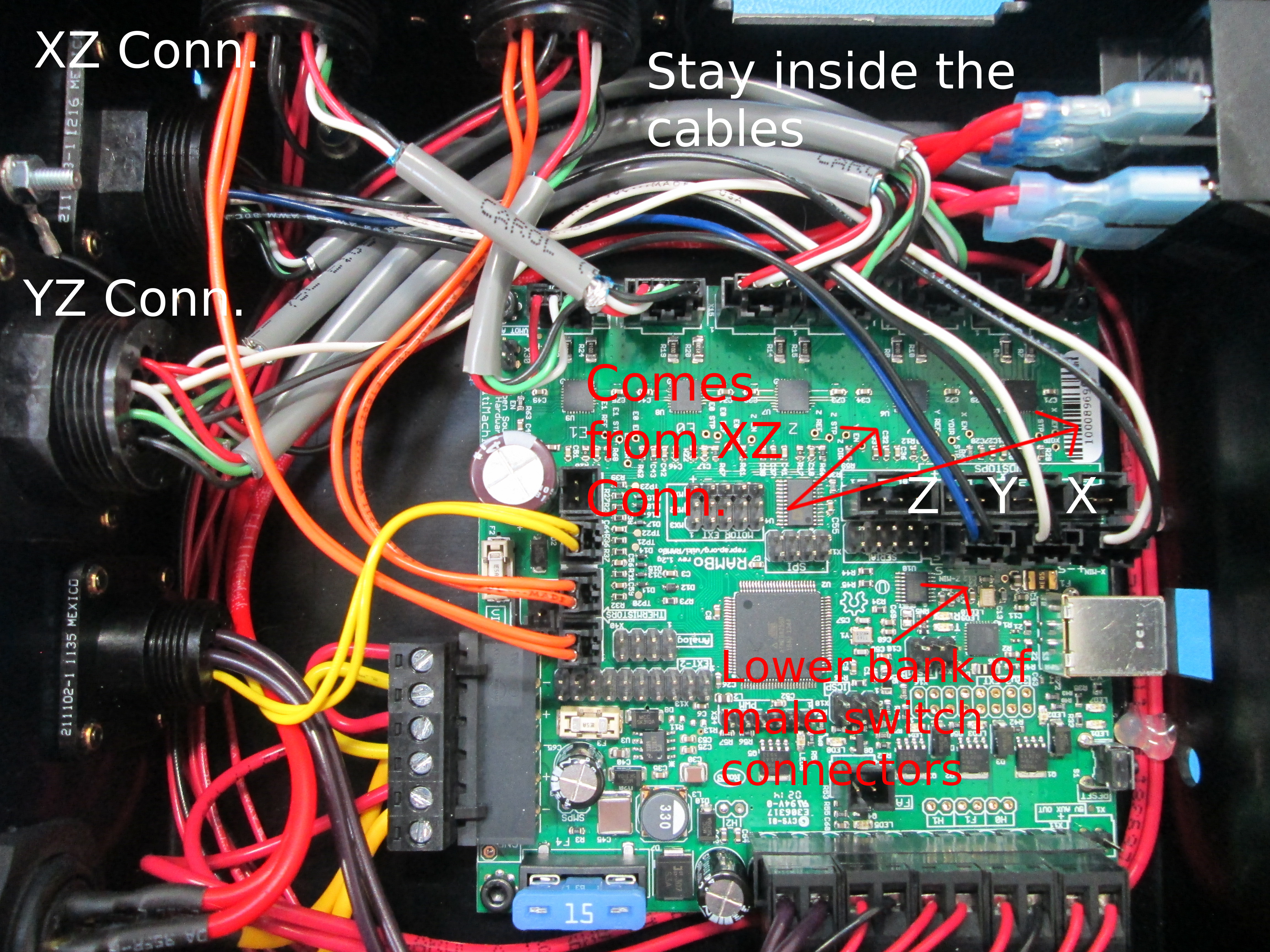
Connect X, Y, and Z Switch cables to the lower bank of RAMBO switch-male-connector housings by routing the wires under the gray motor cables in the order below
Connect the X-switch cable(black and white cable) to the RAMBO X-connector male housing (far right position). Note that the X-switch cable is from the XZ connector, Pin 6 &10, about the middle of the connector
Connect the Z-switch cable(black and blue cable) to RAMBO Z-connector male housing (far left position). Note that the Z-switch cable is from the XZ connector, Pin 9 &13, on the side toward you
Connect the Y-switch cable(black and white) to RAMBO Y-connector male housing (middle position). Note that the Y-switch cable is from the YZ connector
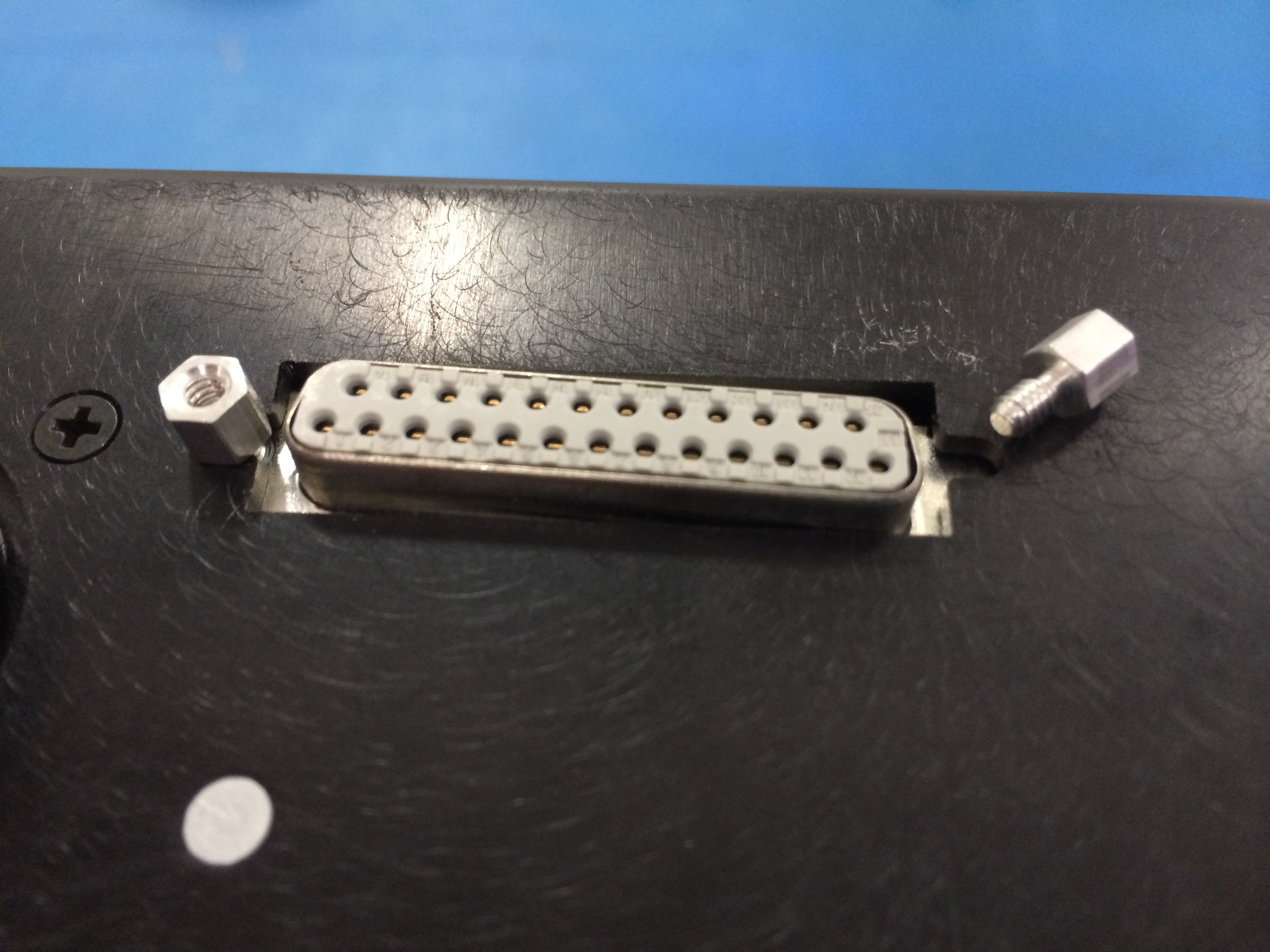
Insert the 25Pin connector from below-inside the box with the BLUE wire on the left and the cut edge of ribbon cable facing the back as shown
Mount the 25Pin connector in place with 2x 4-40 standoffs by screwing from outside, tighten the standoff-screws to secure the connector to the box chassis
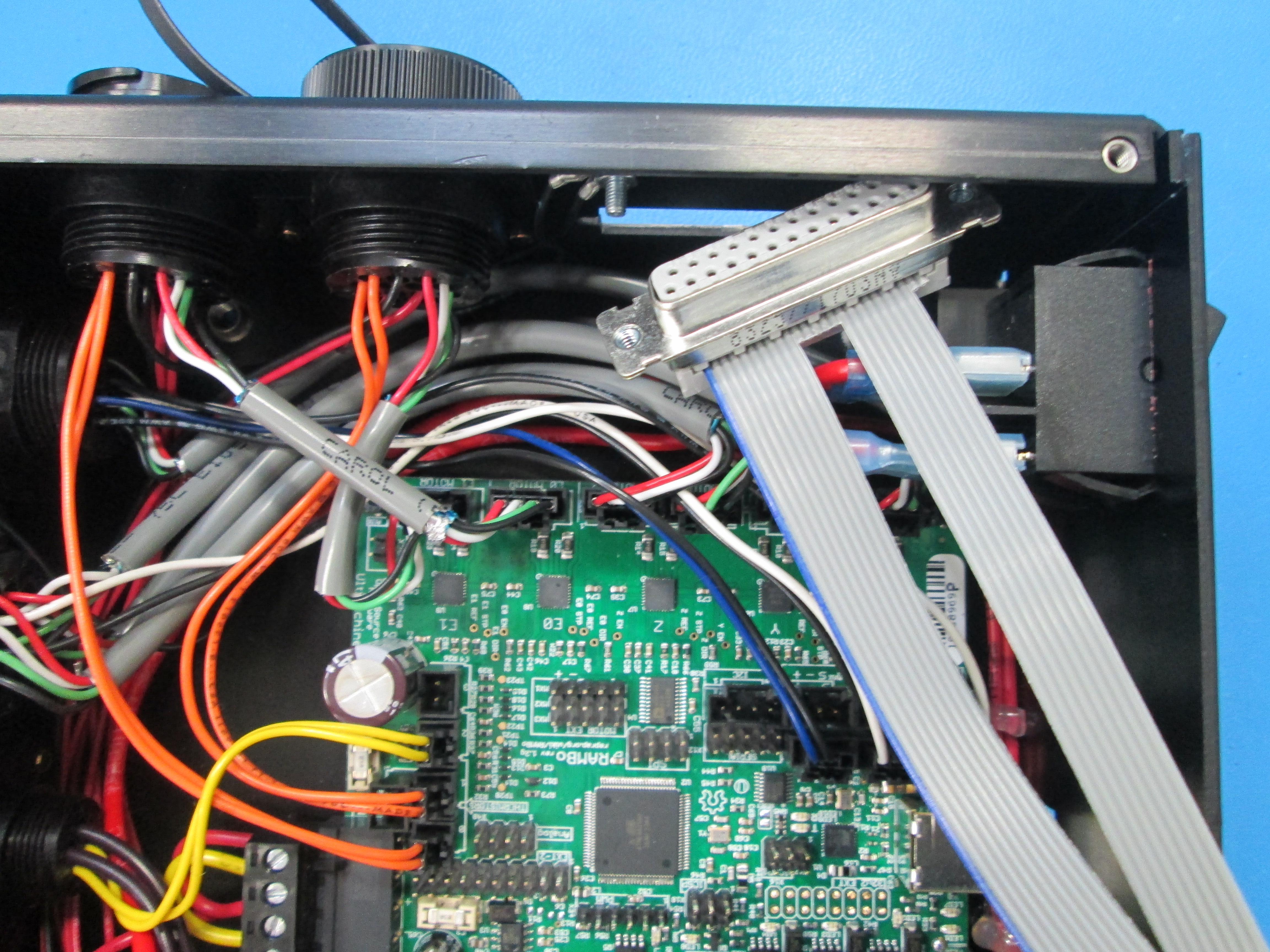
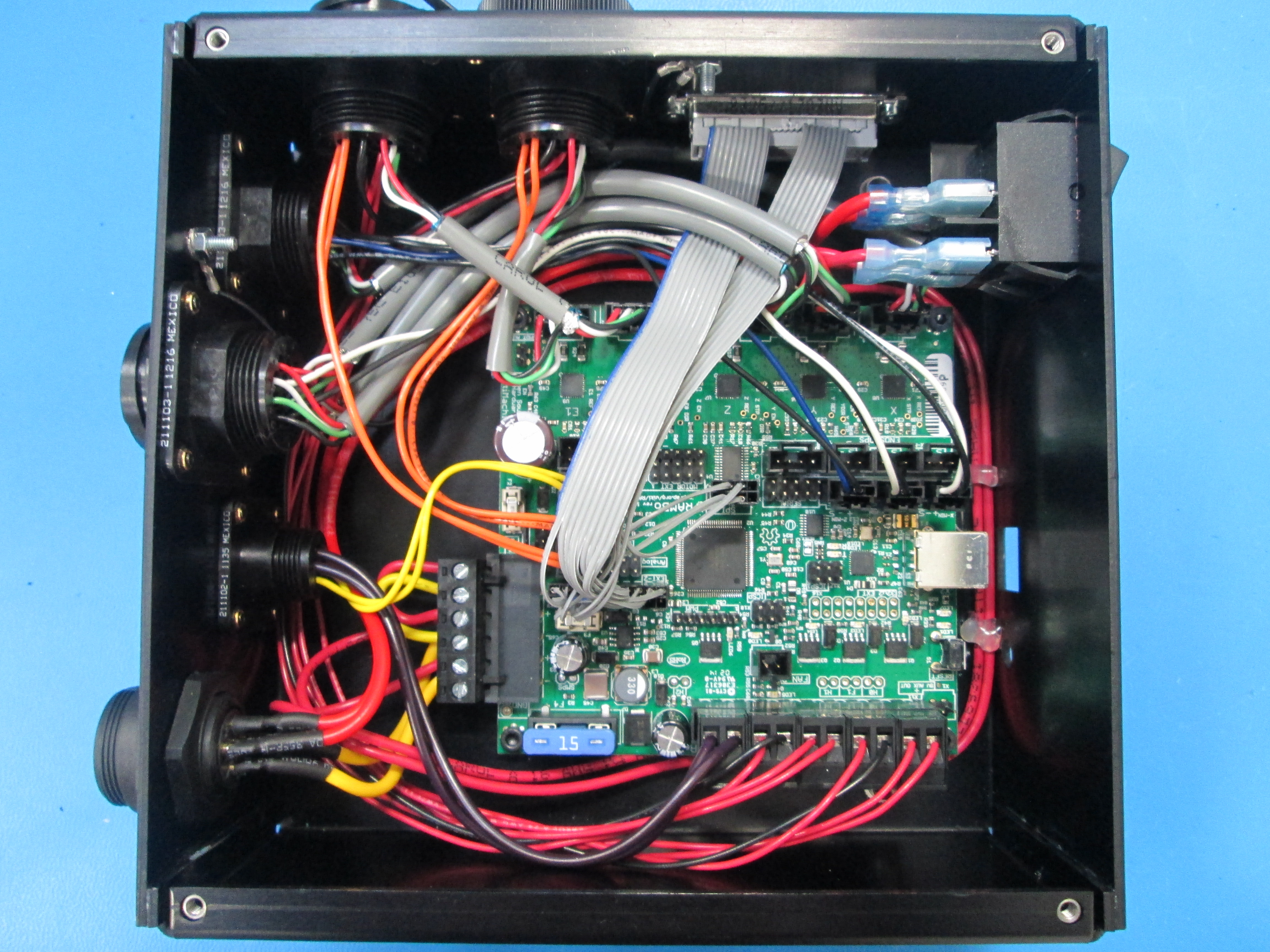
Route the LCD ribbon wires under the Y motor cable, and Z left and right motor cables as shown
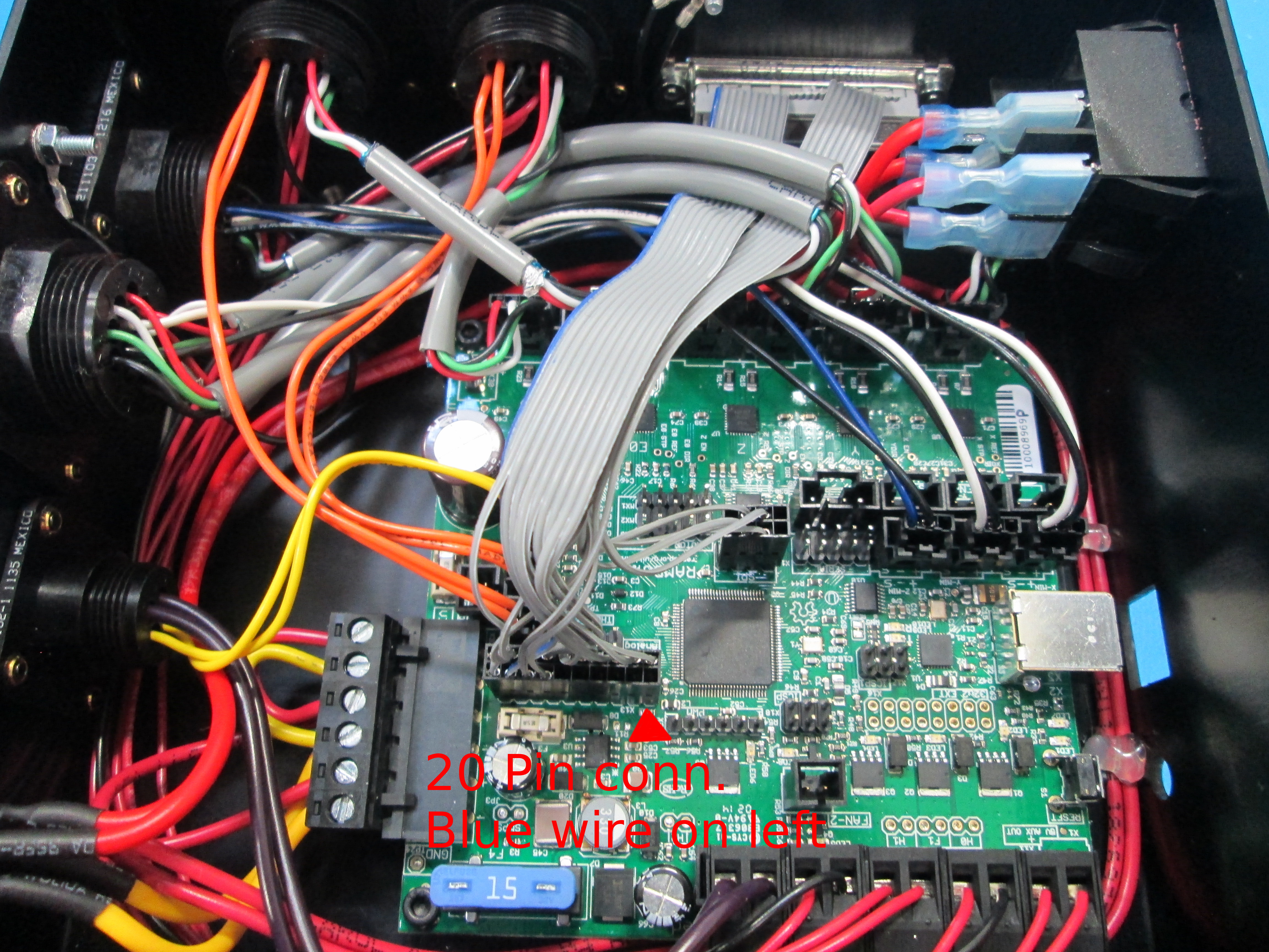
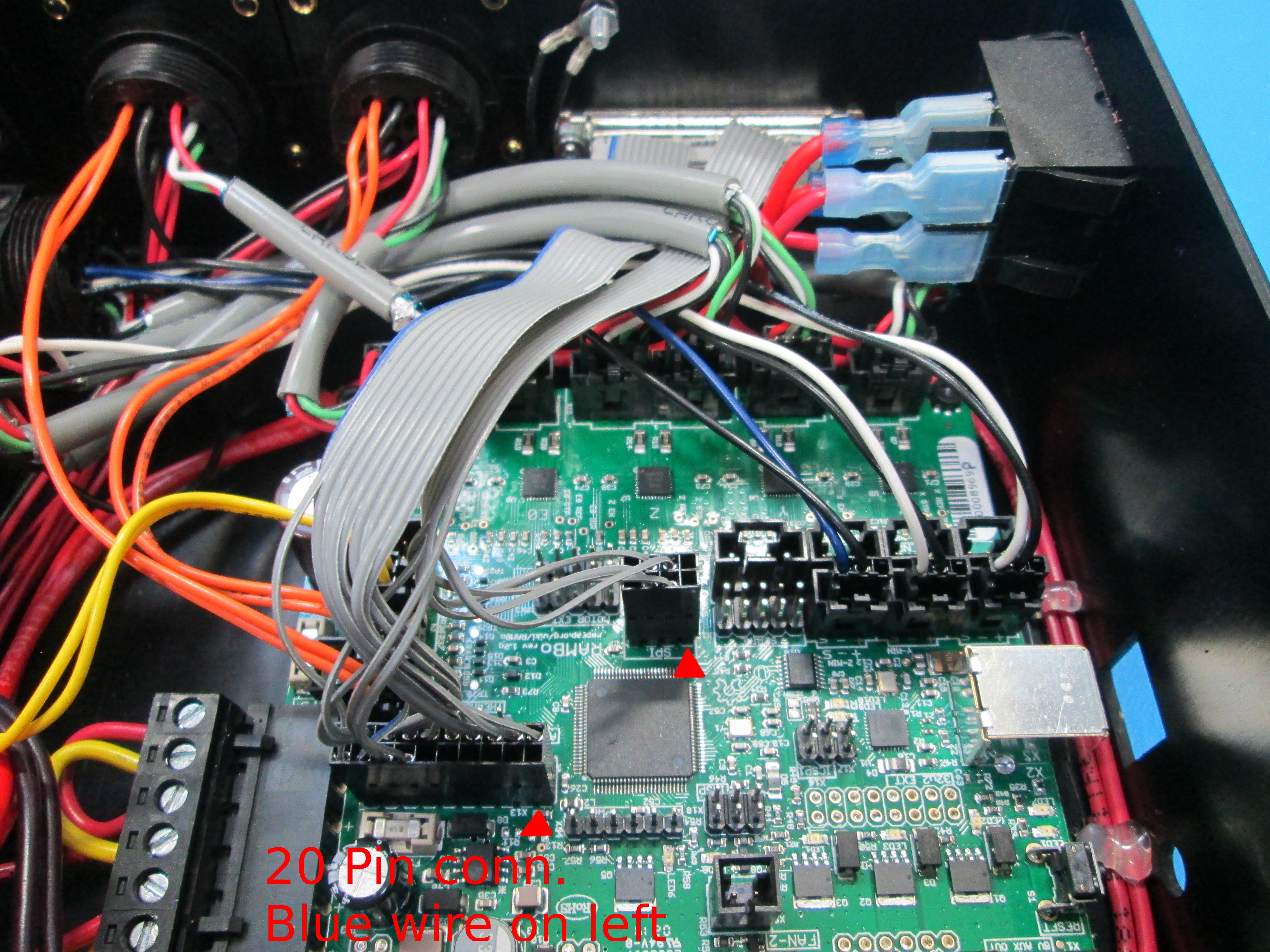
Plug the 20pin connector housing (bigger ribbon wire) to the 20pin male connector on Rambo; make sure the BLUE wire is on the left and the triangle mark is on bottom right as shown
Plug the 8pin connector housing to the 8pin male SPI connector on Rambo making sure that the triangle mark is on the bottom right as shown
Red triangles in pictures mark location of triangles on the connectors
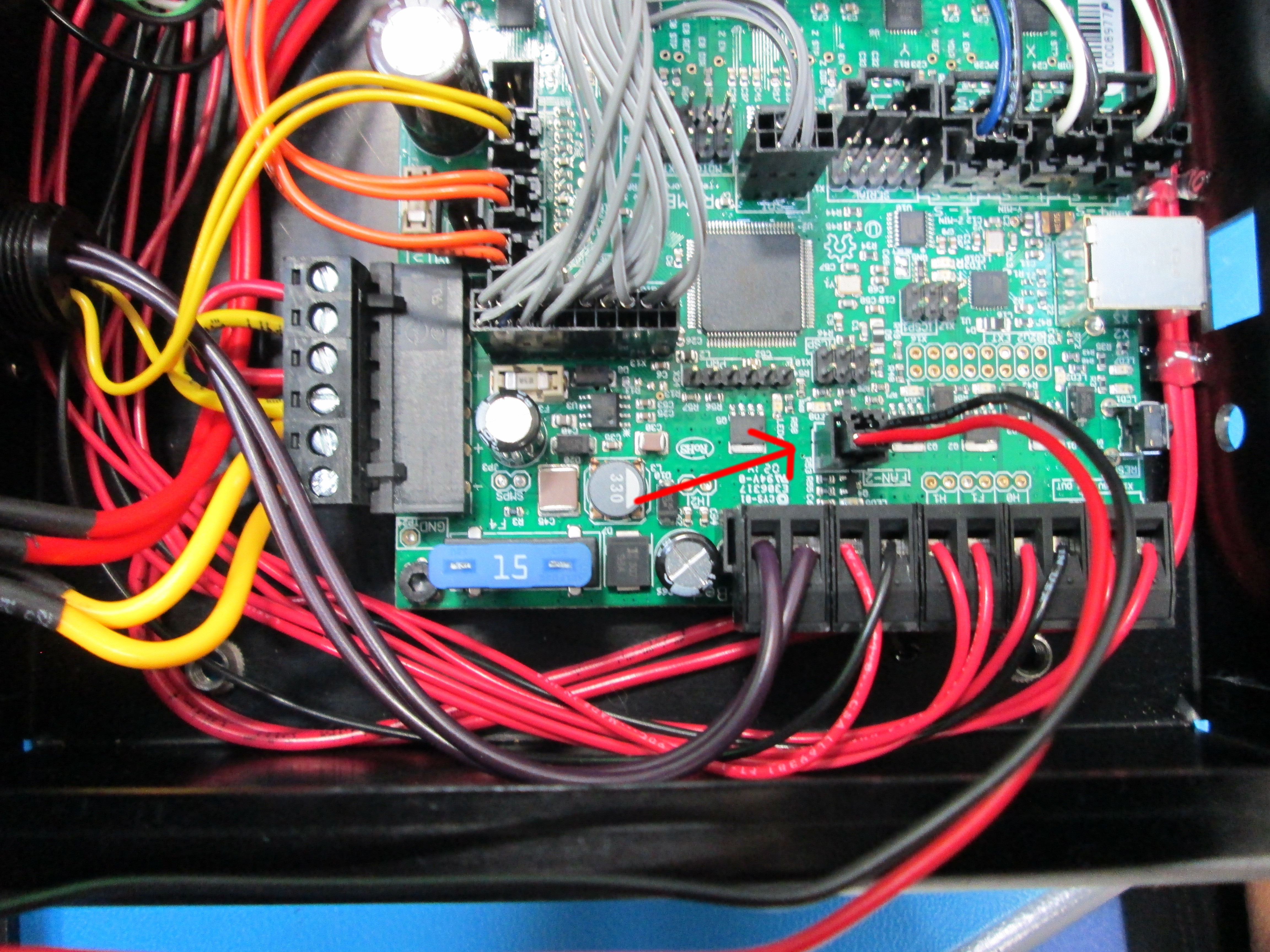
Connect Fan cable into RAMBO 2pin fan connector housing as shown
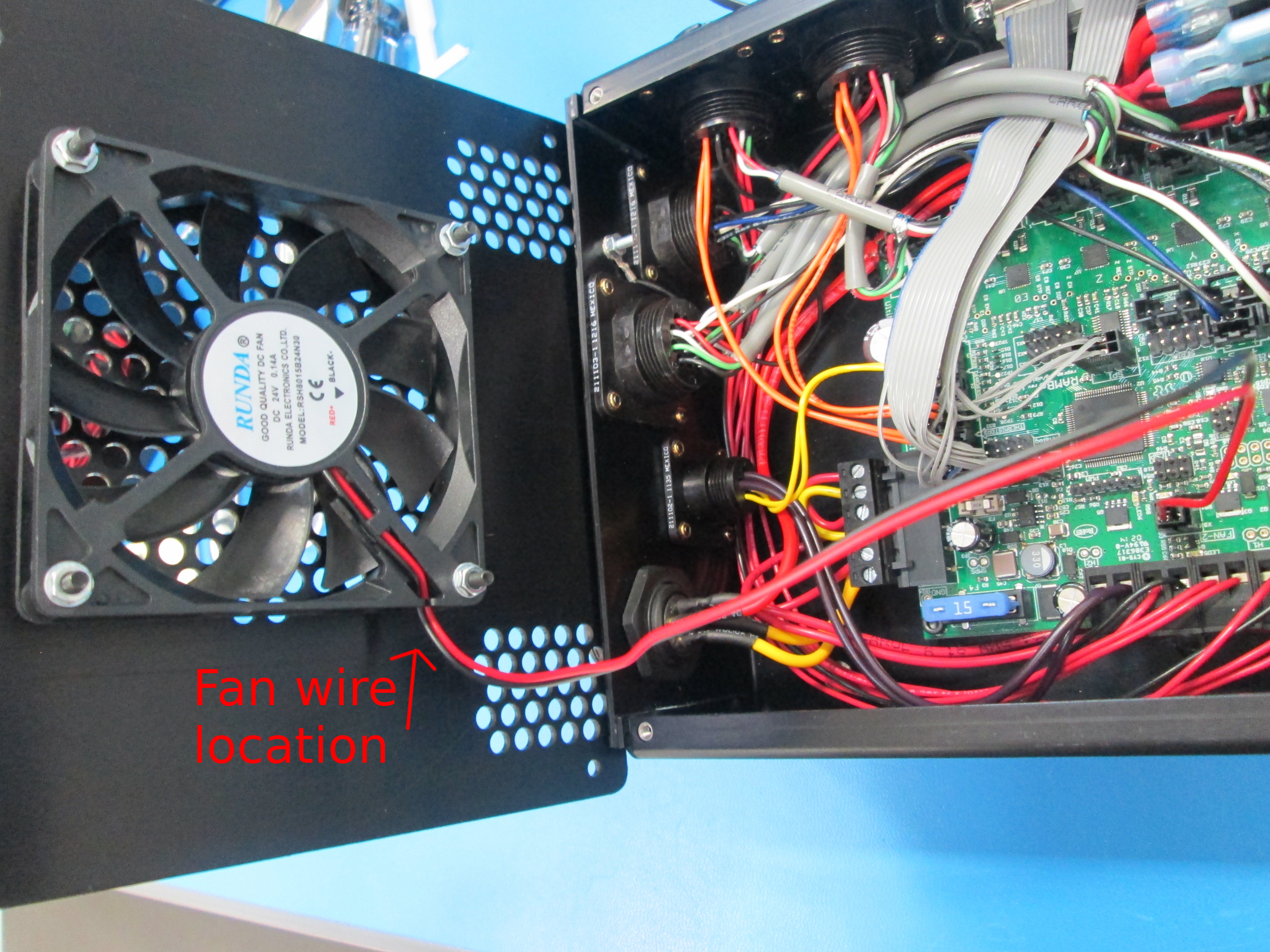
Install cover using 4x M3x12 screws and M3 washers. Make sure fan wires are located in the lower left corner of the cover once the cover is installed as shown