Open HardwareAssembly Instructions
Guides for installation and assembly of the LulzBot line of products made by FAME 3D LLC.
Guides for installation and assembly of the LulzBot line of products made by FAME 3D LLC.
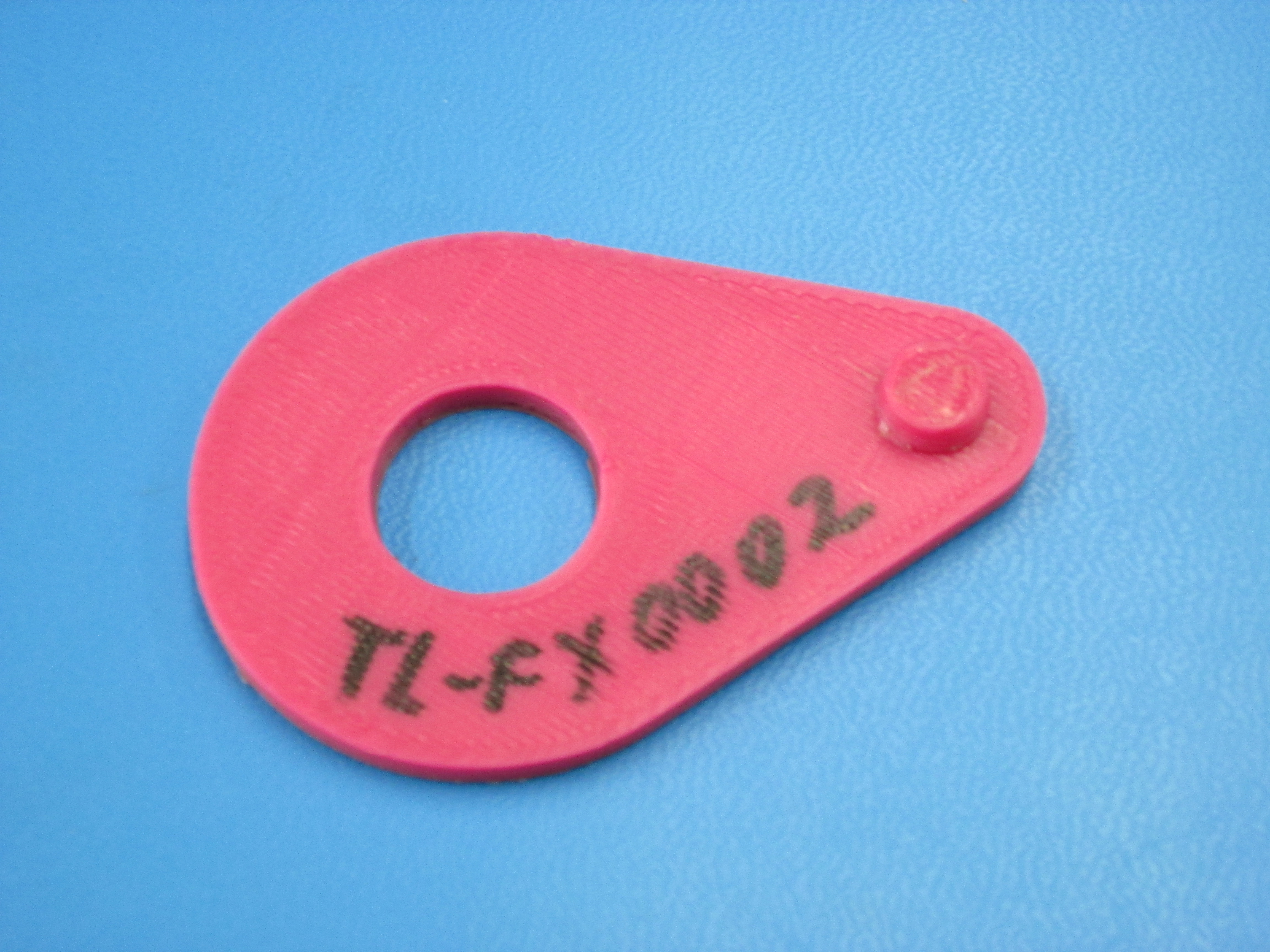
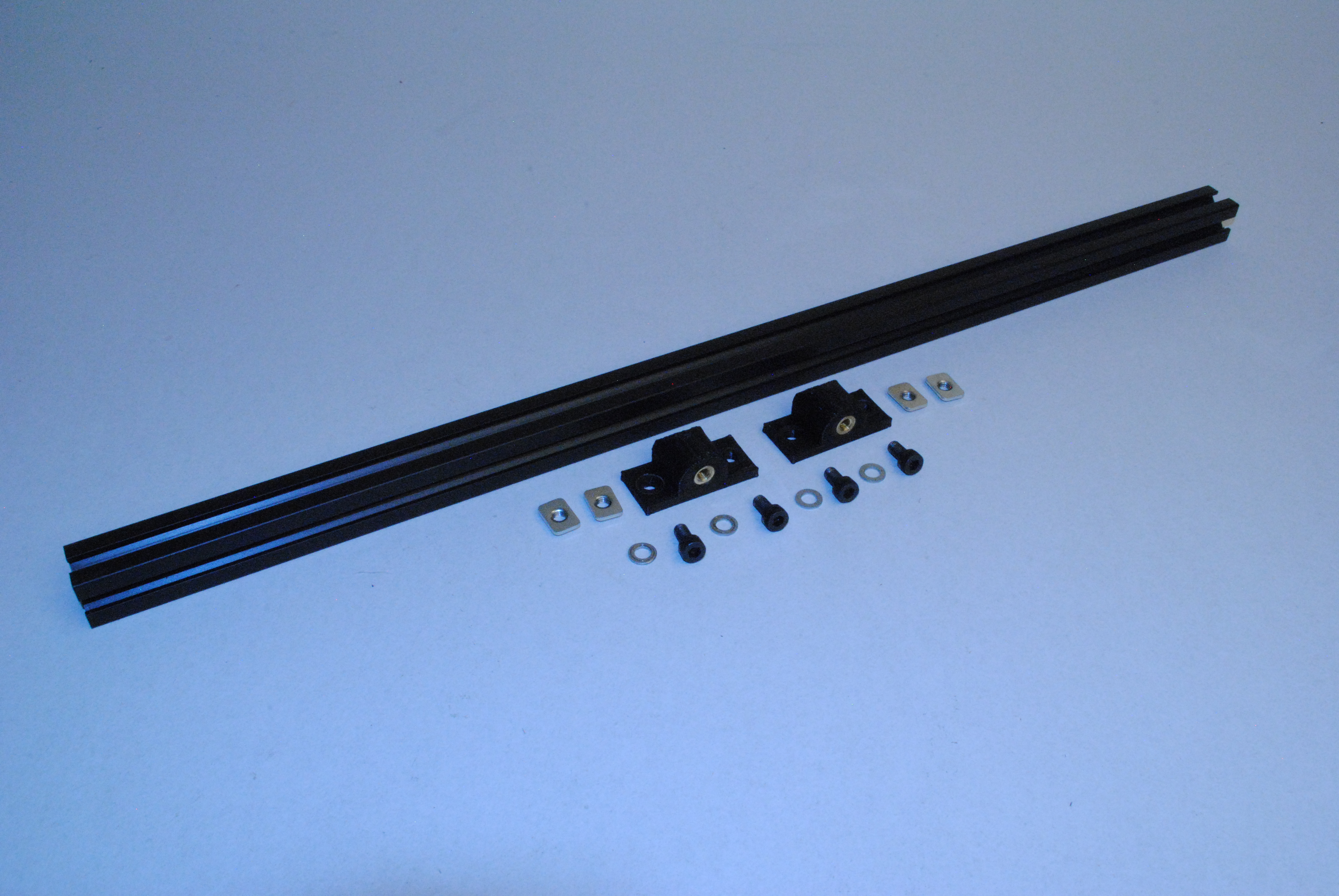
Components:
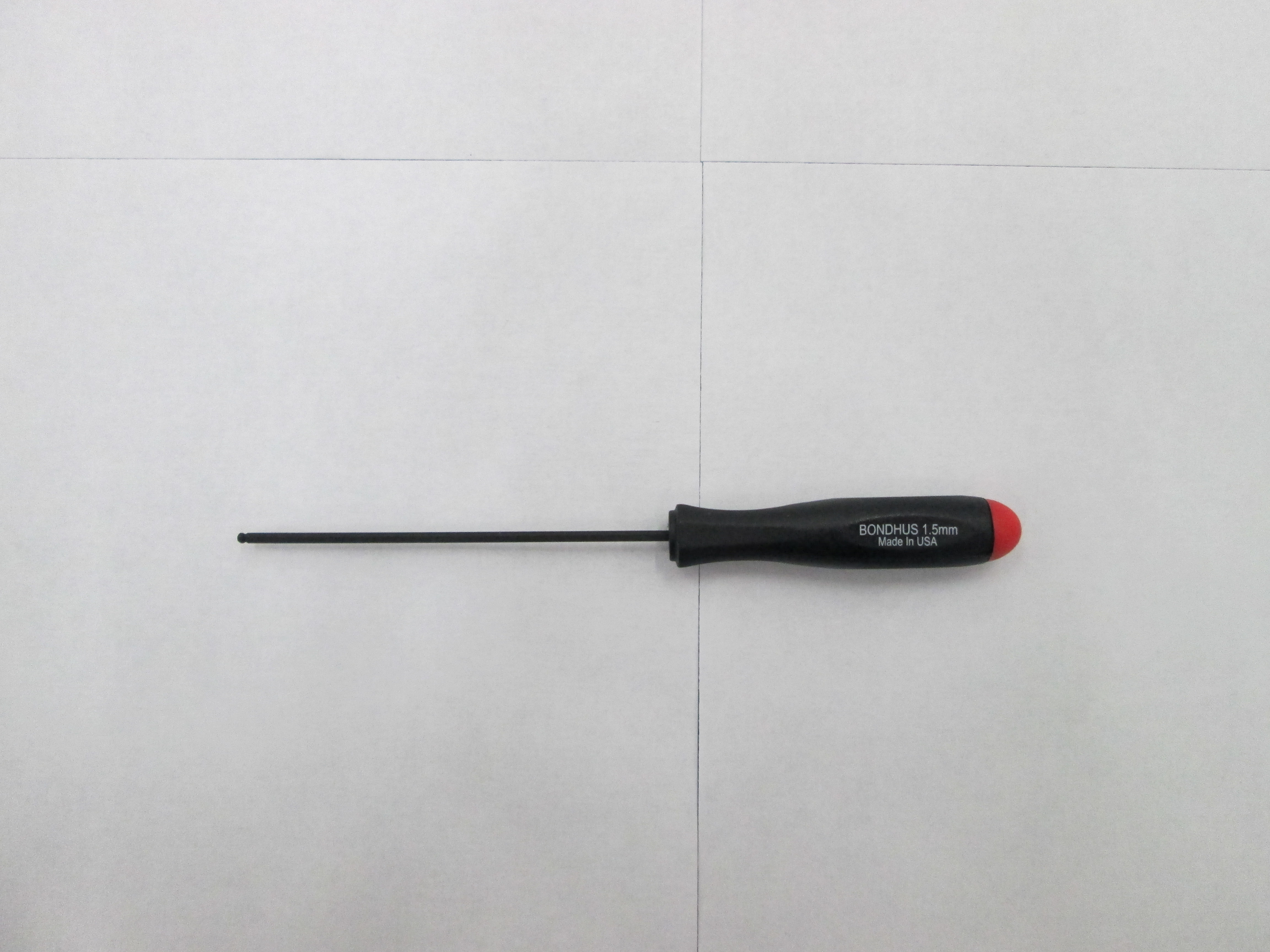
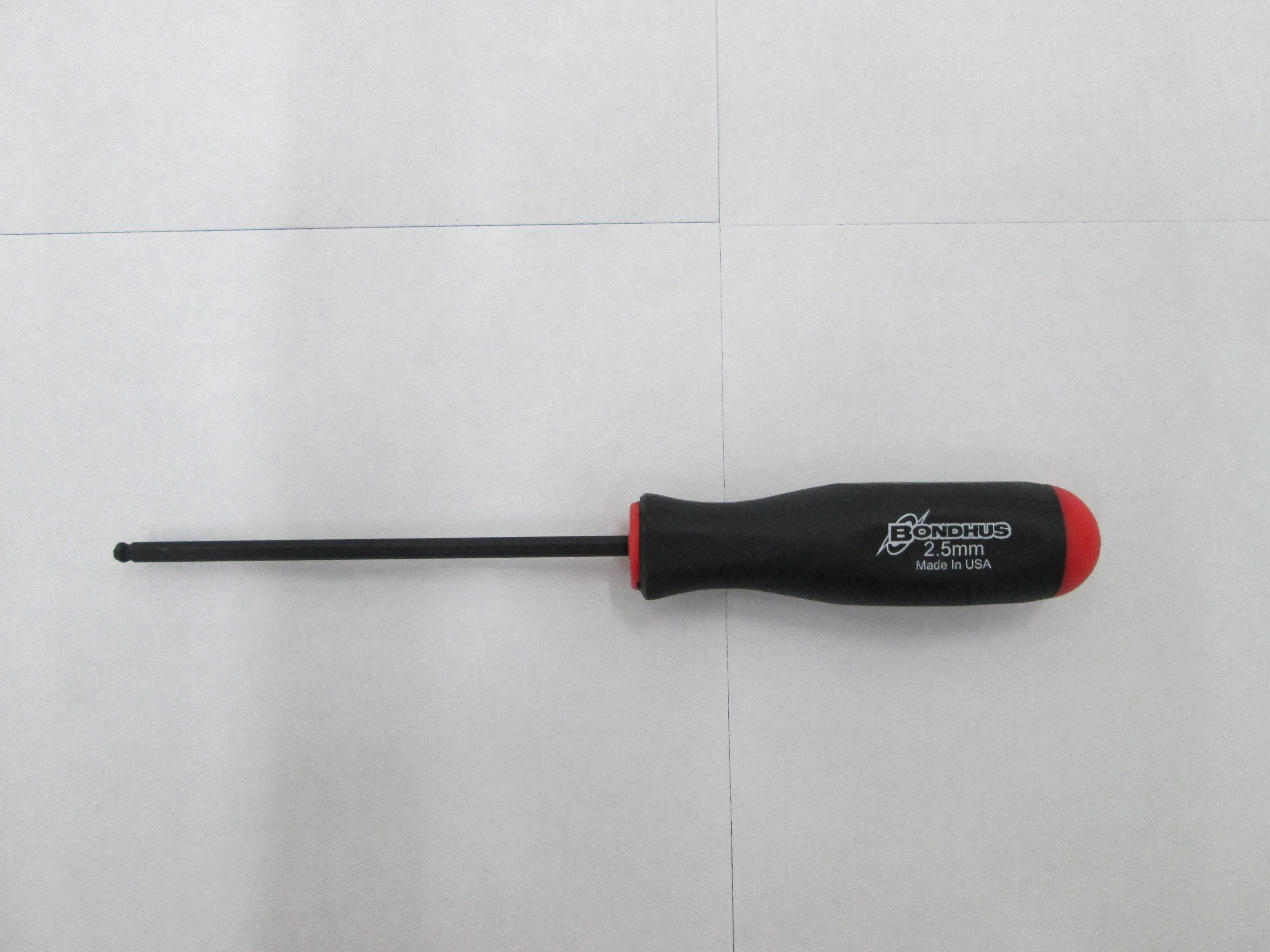
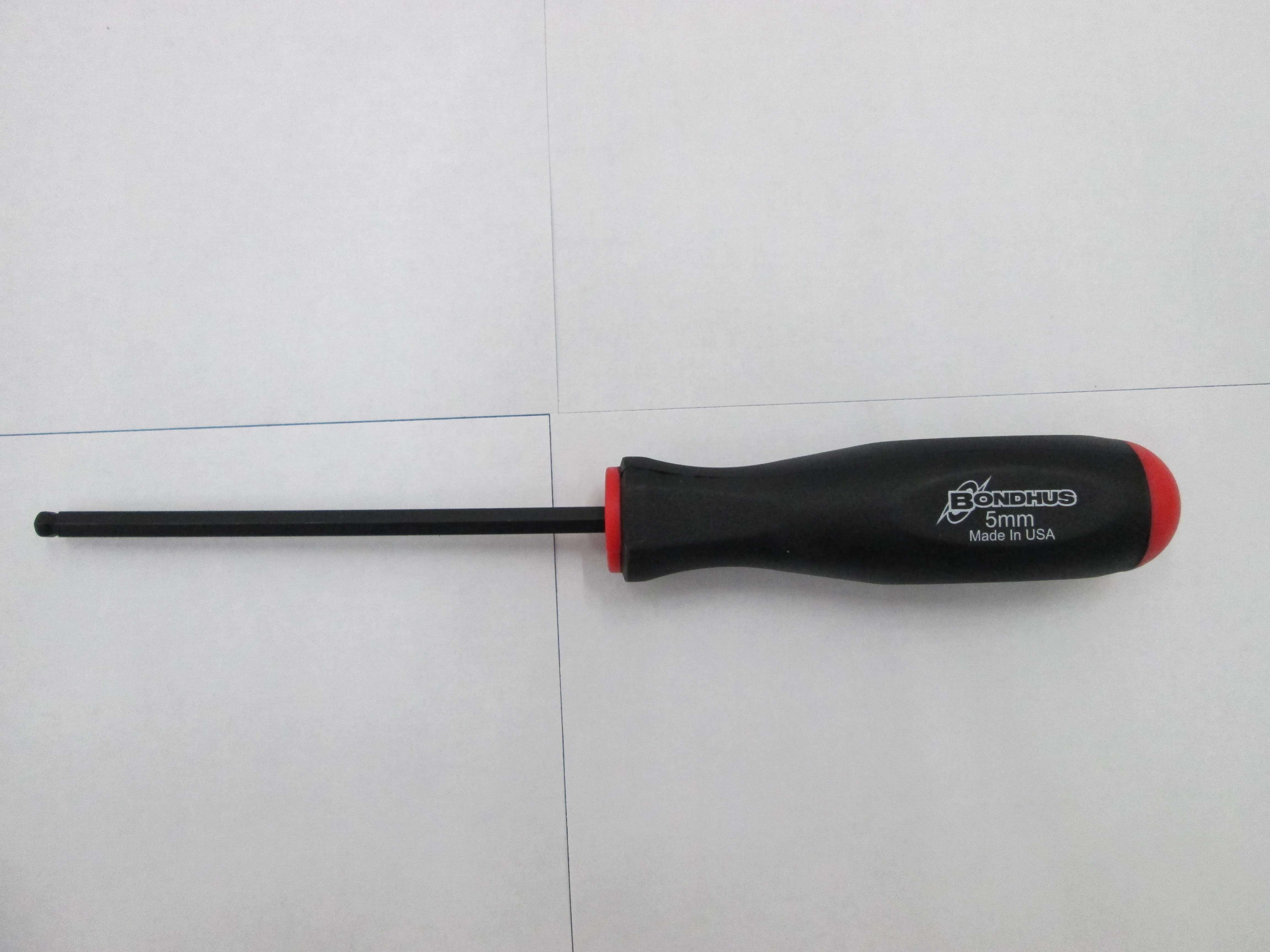
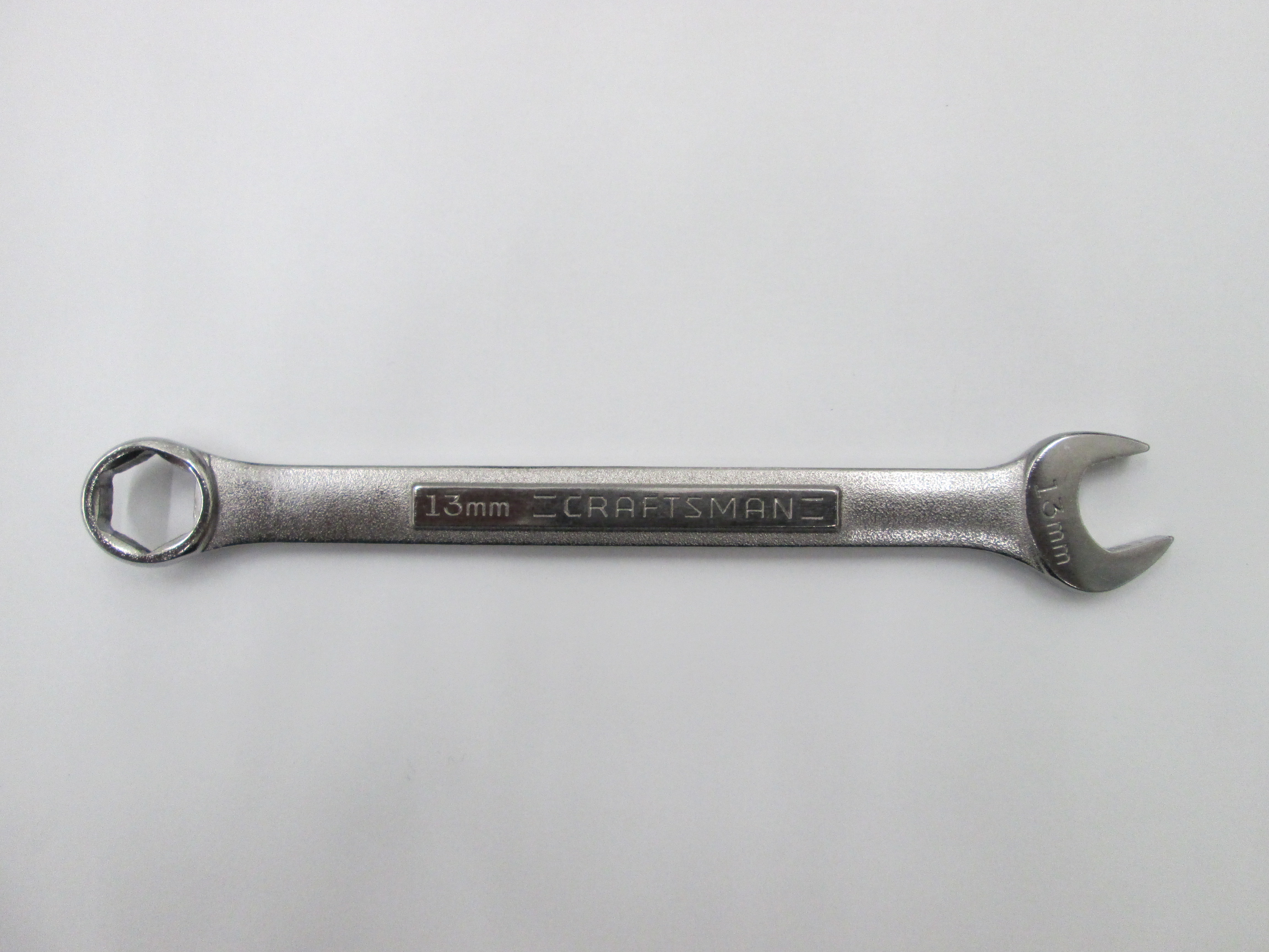
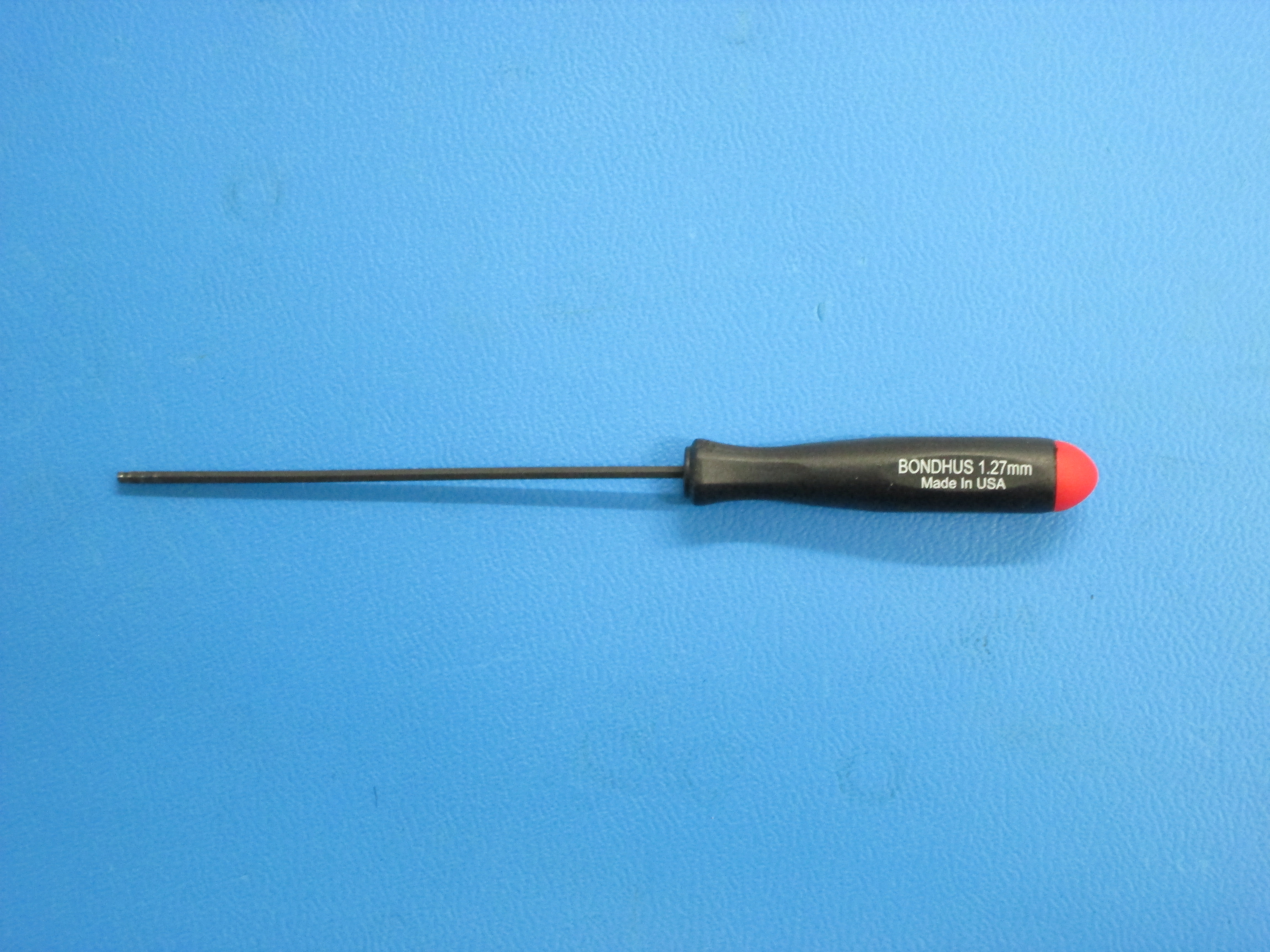
Tools:


Build 2 of these assemblies.
Slide all 4 T-nuts into one side of the extrusion.
Using the M5 x 10 SHCSs and M5 Washers, install two Y mount tables to the extrusion.
Location is not important at this point, just be sure the mounts are facing the same direction.

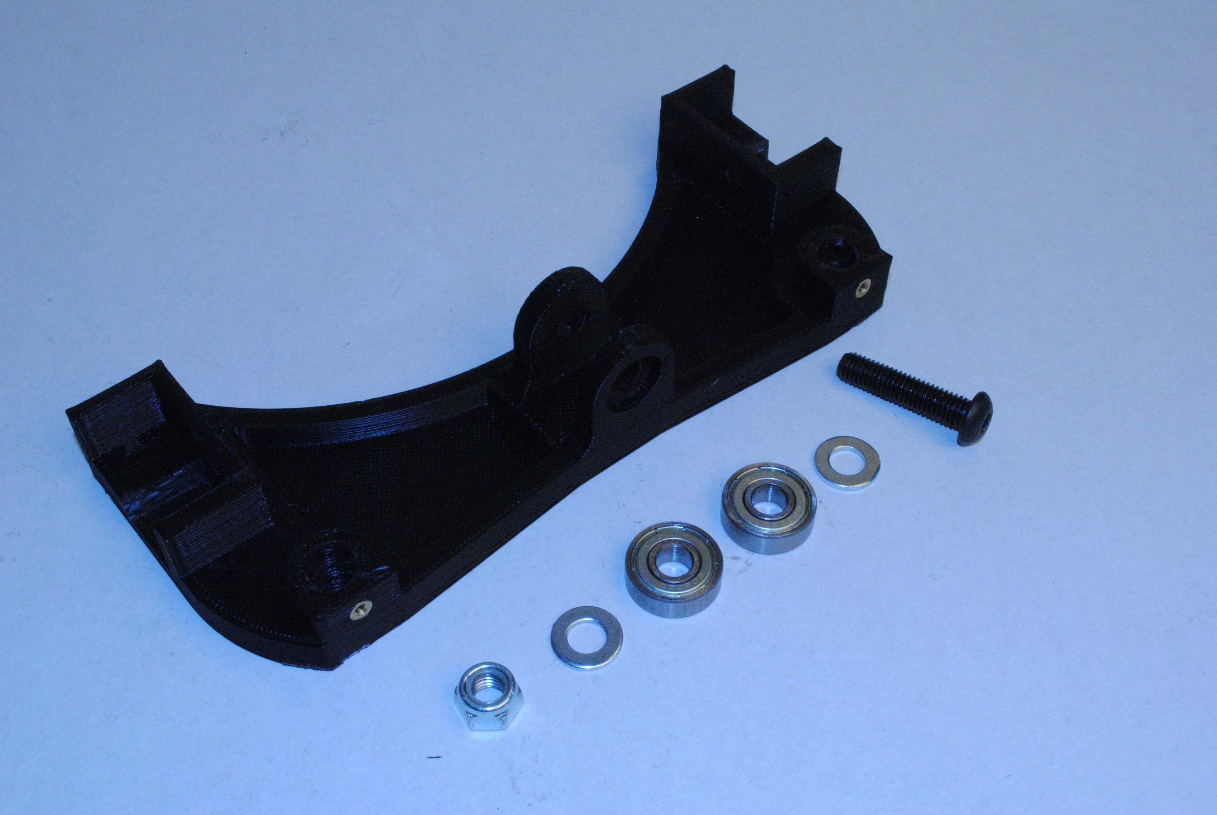
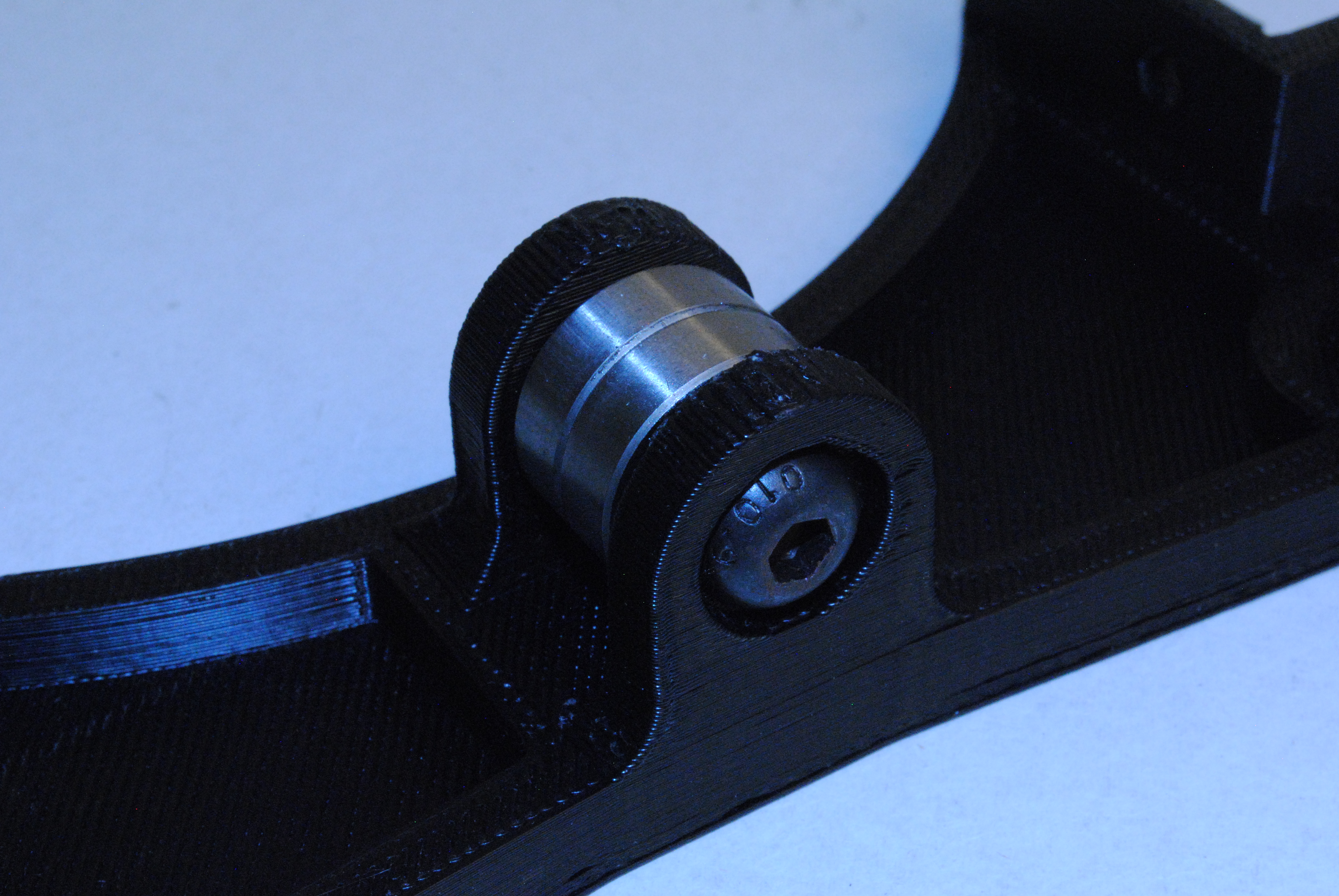
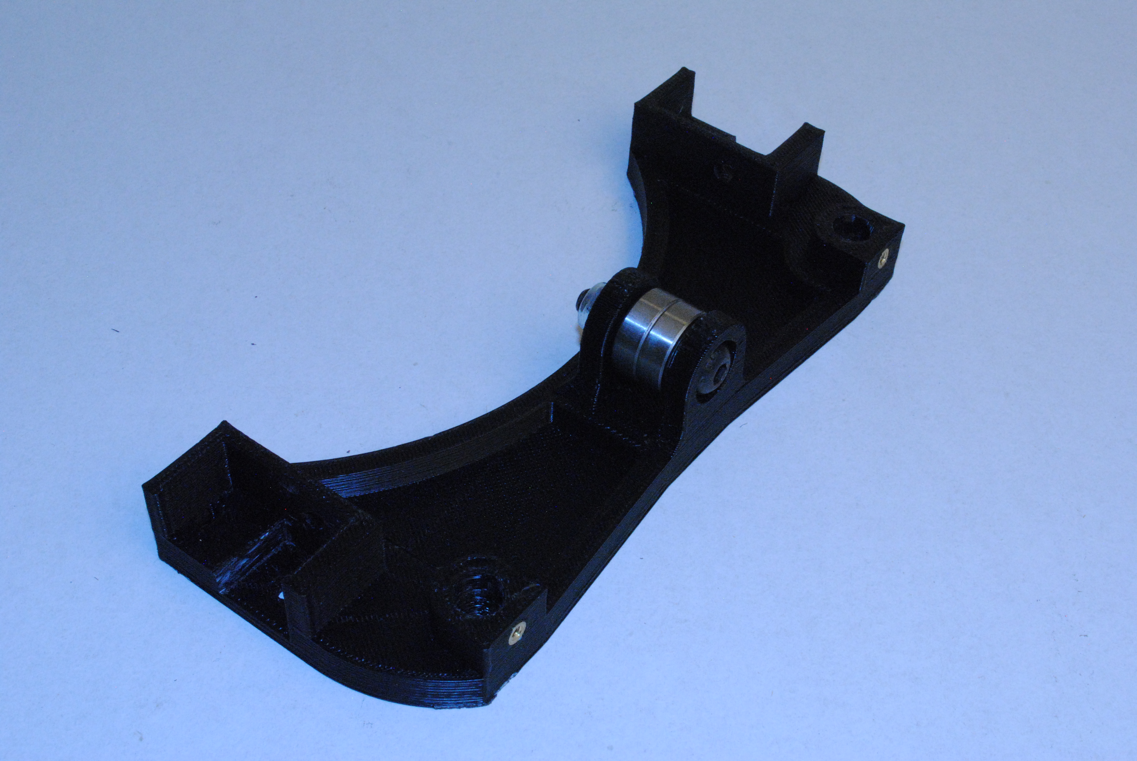
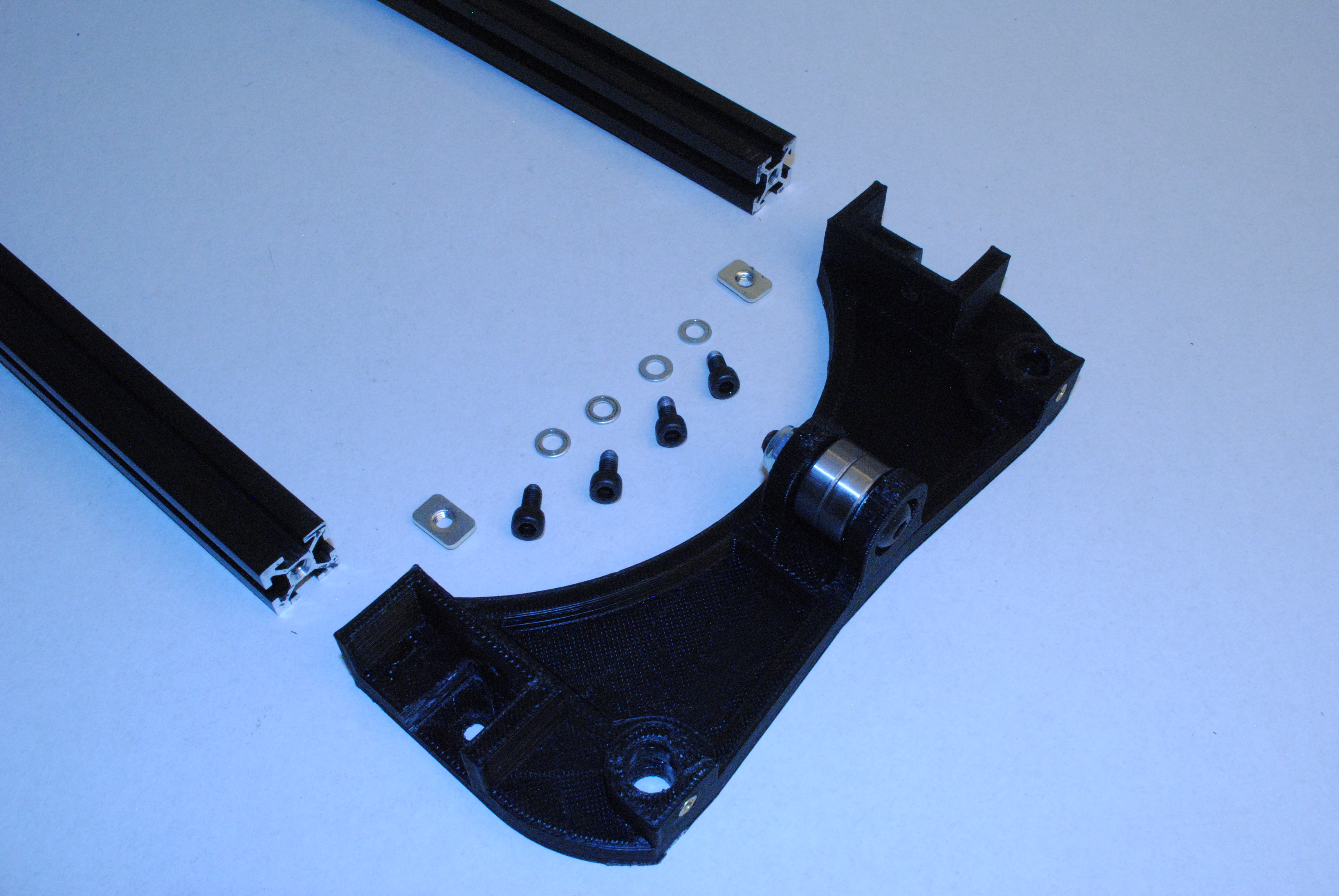
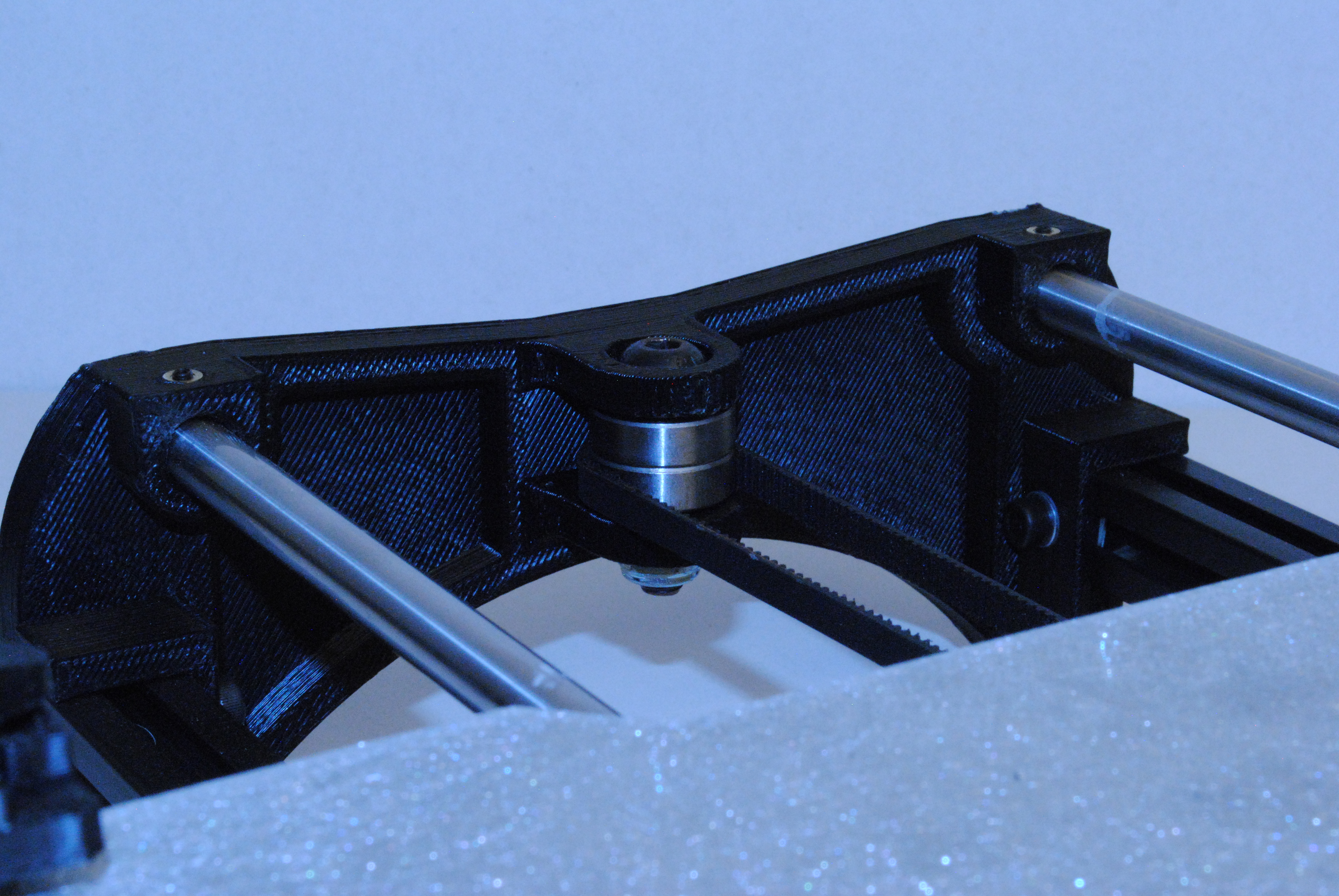
Install 2x 608 bearings onto the Y idler using a M8 x 35 BHCS, M8 washers and a M8 nyloc nut.
There is no washer under the head of the bolt or the nut.
Tighten the bolt all the way down.

Take two extrusions with Y mounts on them. With the mounts on the top and inserts facing outwards, slide one M5 T-nut into the end of each one.
Install the Y motor mount onto the extrusion and secure with 2x M5 x 10 SHCS with M5 Washers.
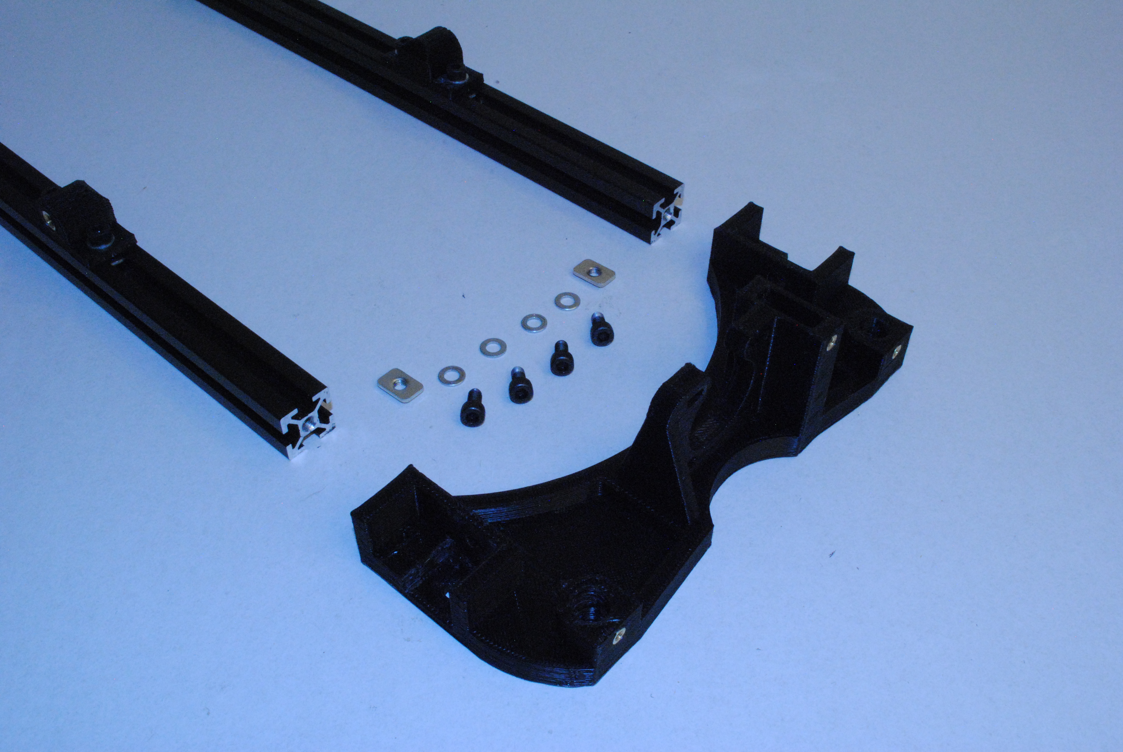

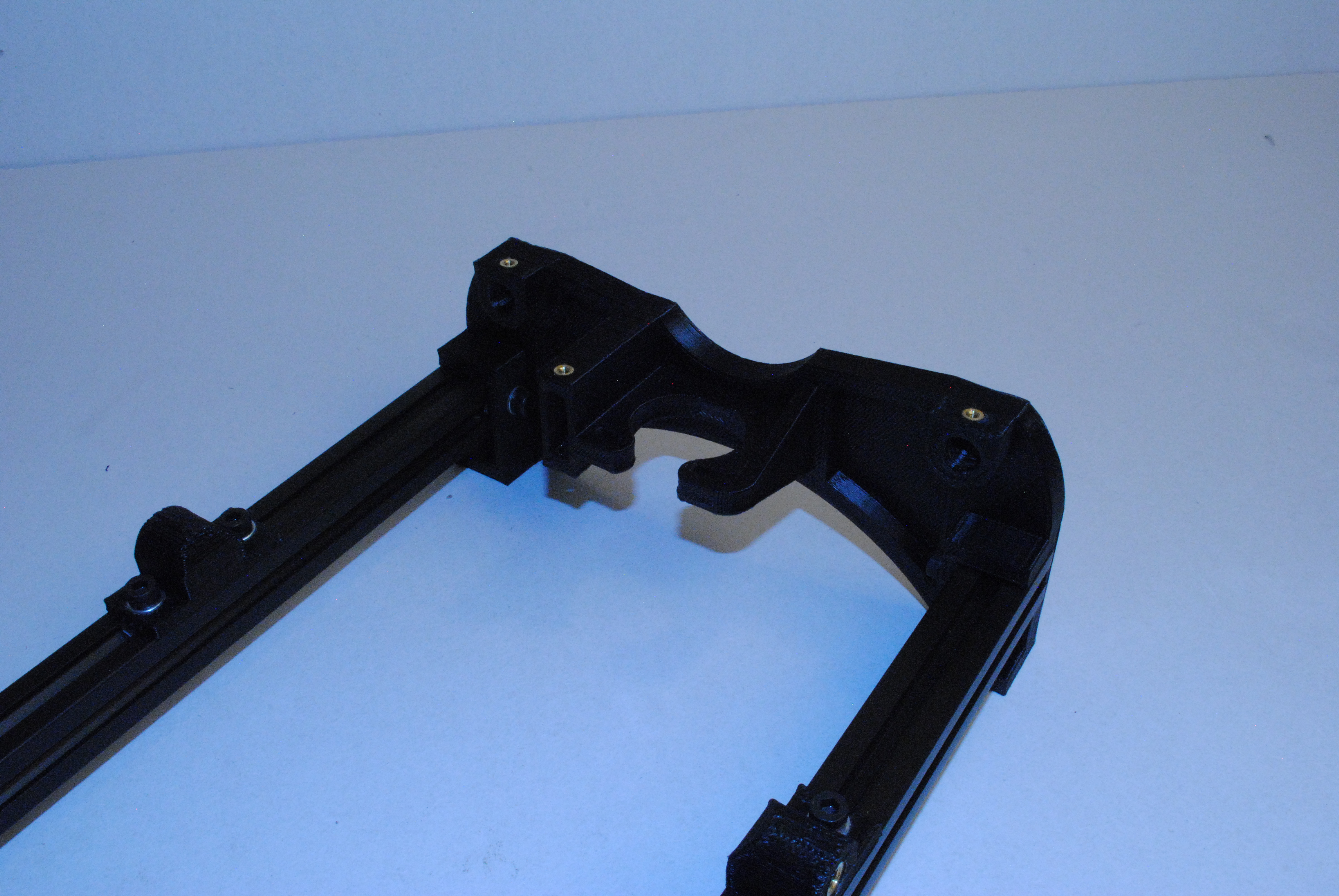
Take 2x M5 T-nuts and slide them into the inside slot on the extrusions.
Using 4x M5 x 10 SHCS and M5 Washers, mount the Y end Idler onto the sub-assembly.
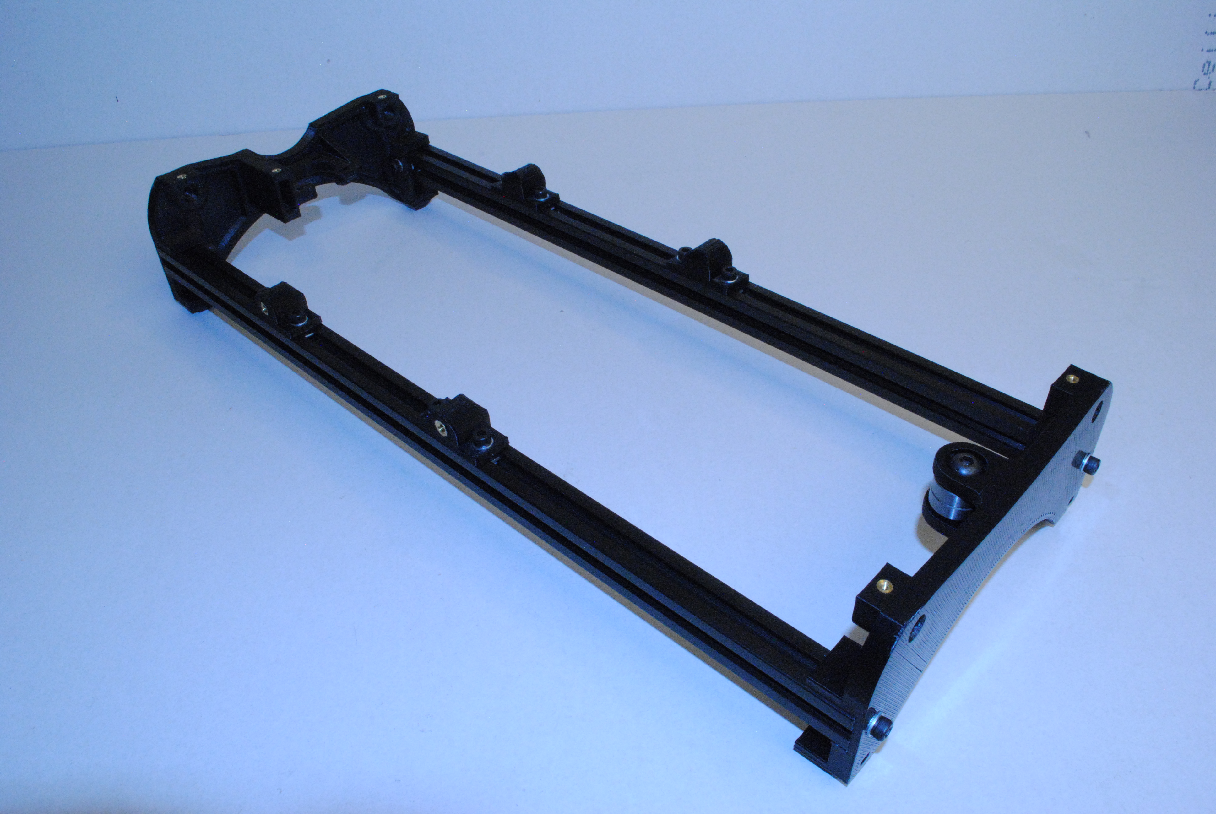

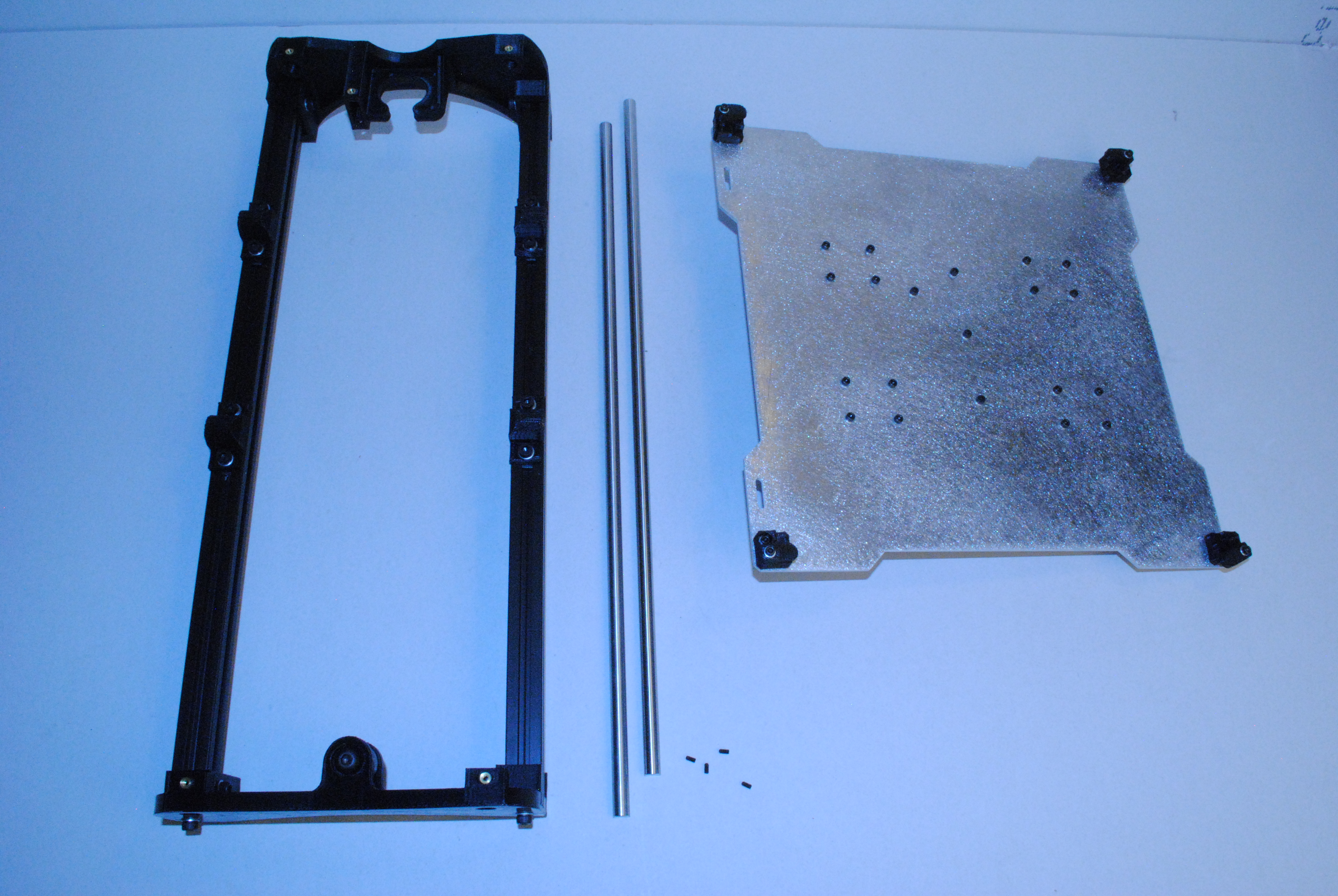
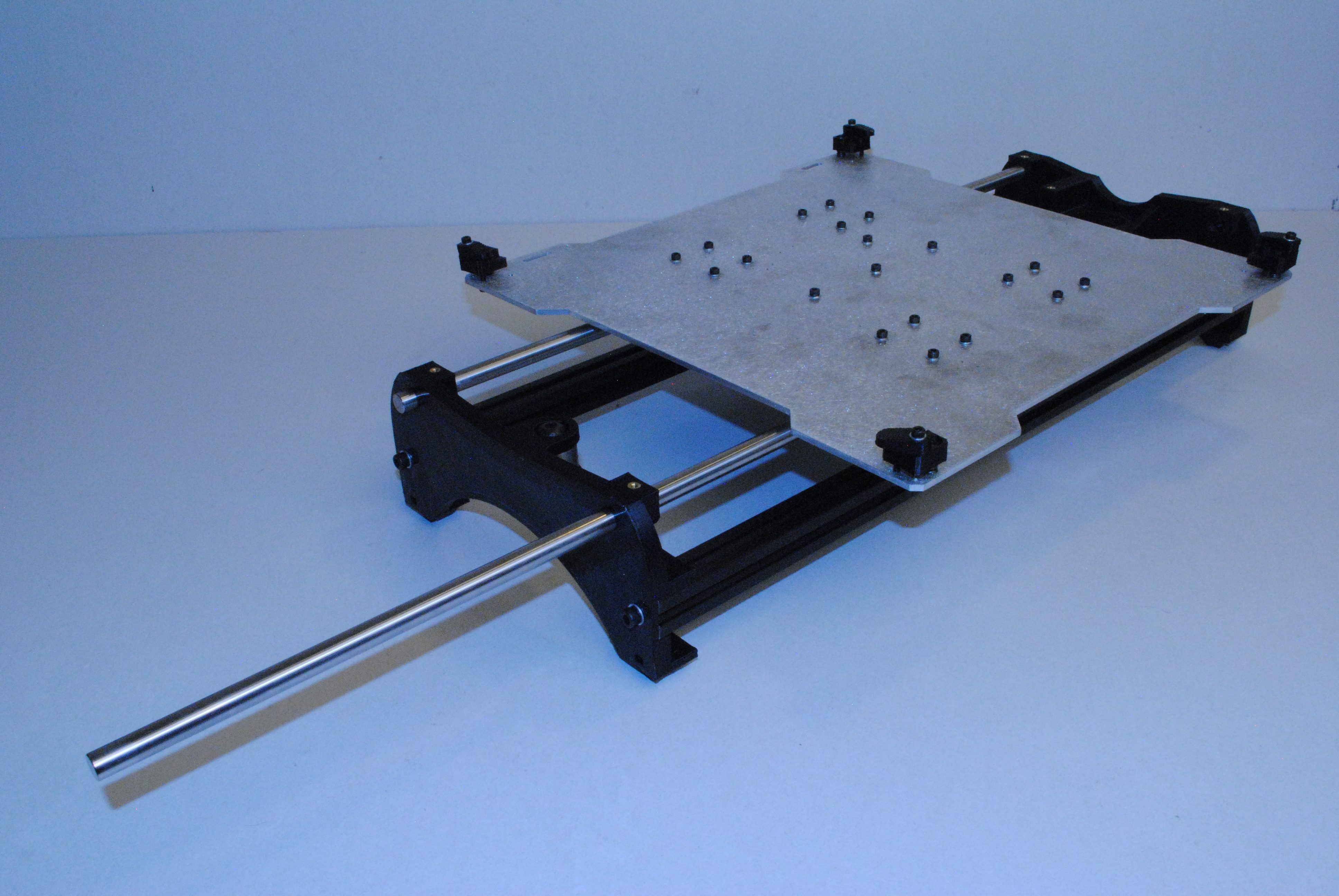
Notice orientation of the Y plate assembly to the Y axis assembly, the slots on the plate must be on the correct side.
Make sure the bearing holders on the Y plate assembly are loose.
Slide one 10mm smooth rod through the Y end Idler, through the Y plate assembly bushings then the Y end Motor.
The end of the rod should be about the same depth on both ends of the assembly.
Repeat with the other smooth rod.
Secure both rods with 4x M3 x 6 set screws, two in each end.
Tighten down the bearing holders on the Y plate assembly, making sure the assembly continues to slide smoothly from one end to the other.
Does the Y plate assembly have any side to side slop in it?
If it does, loosen one of the bushing holders and pull it to the side and re-tighten.
Be sure the Y plate still sides back and fourth smoothly.
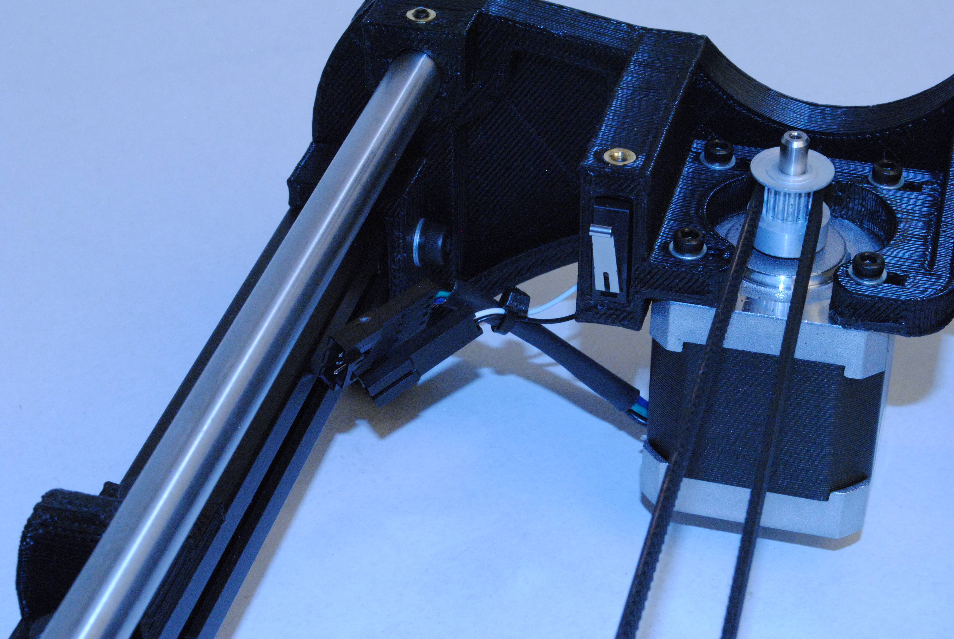
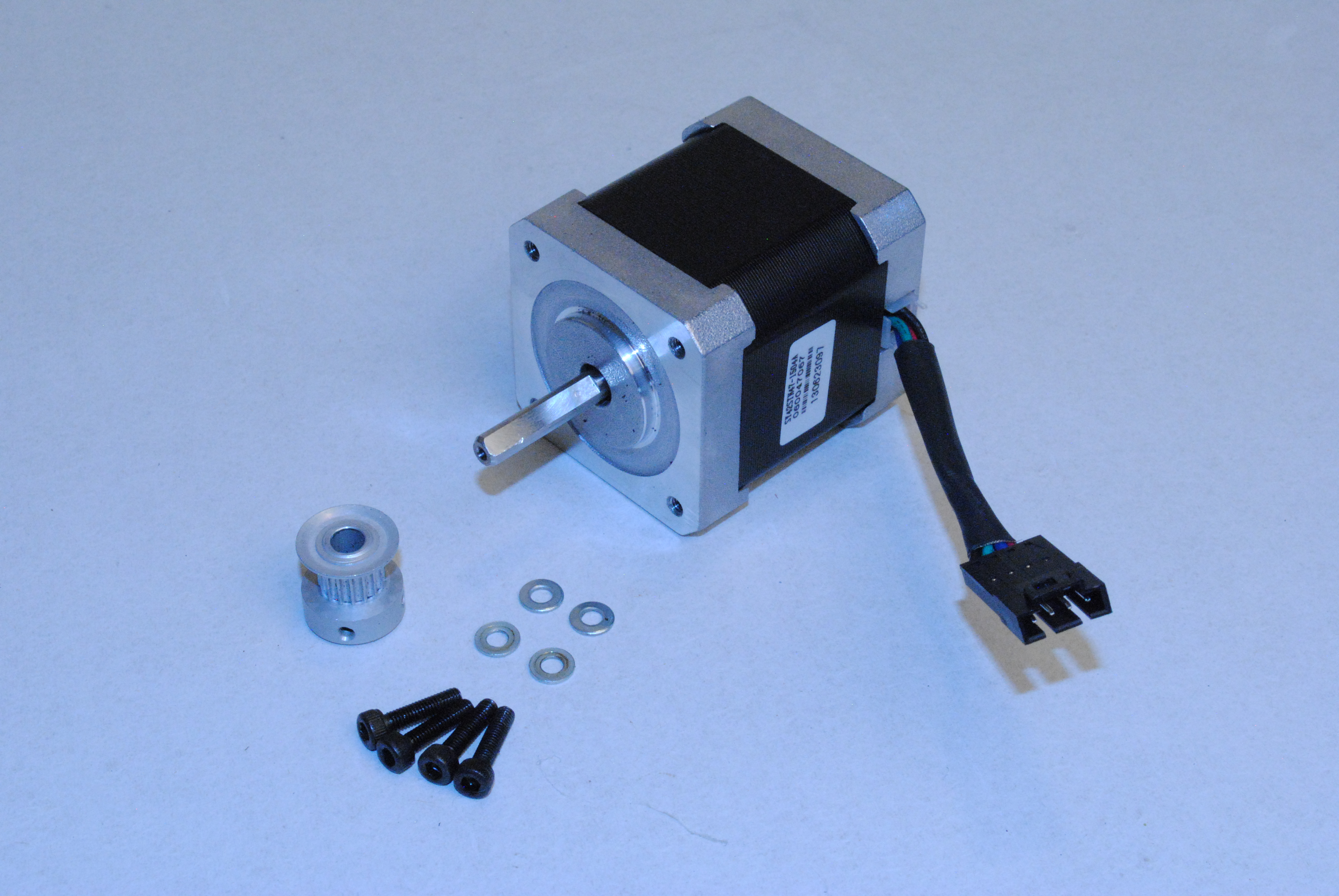
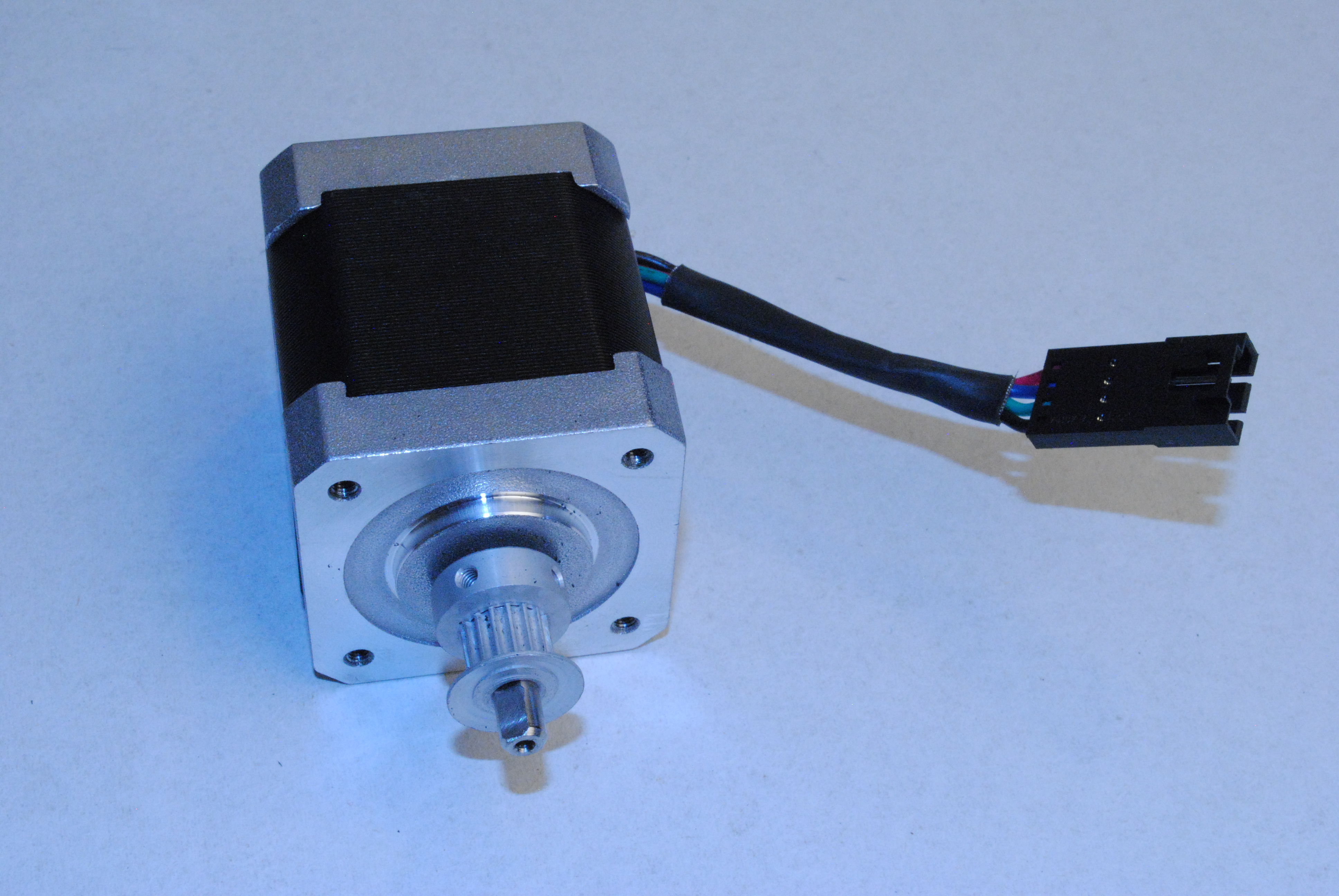
Install the Pulley onto the motor shaft. Be sure one of the set screws lines up with the flat on the motor shaft.
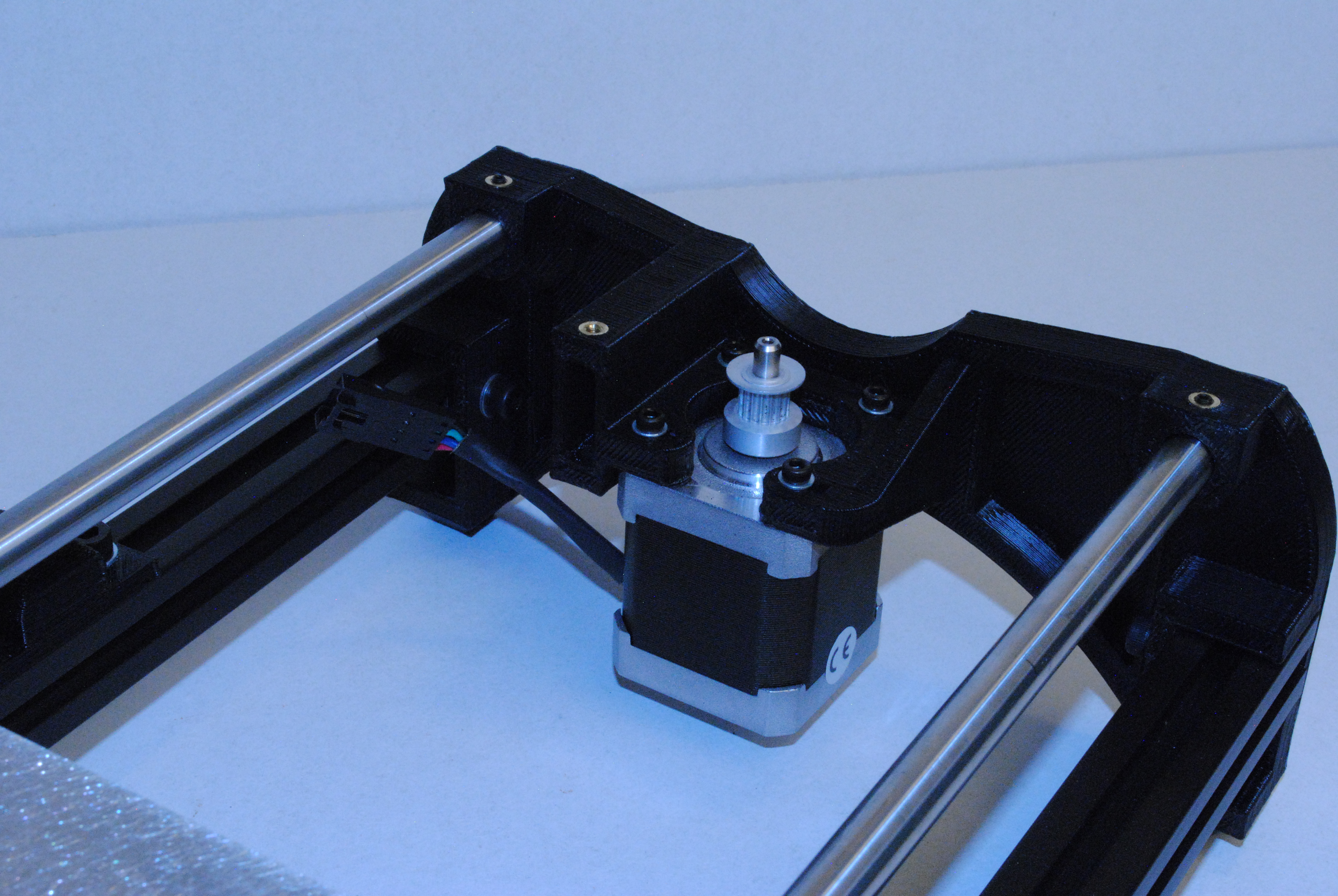
Using 4x M3 x 12 SHCS and M3 Washers, mount the motor onto the Y end motor. Be sure you have the wires going the correct direction.
Flip the assembly over.
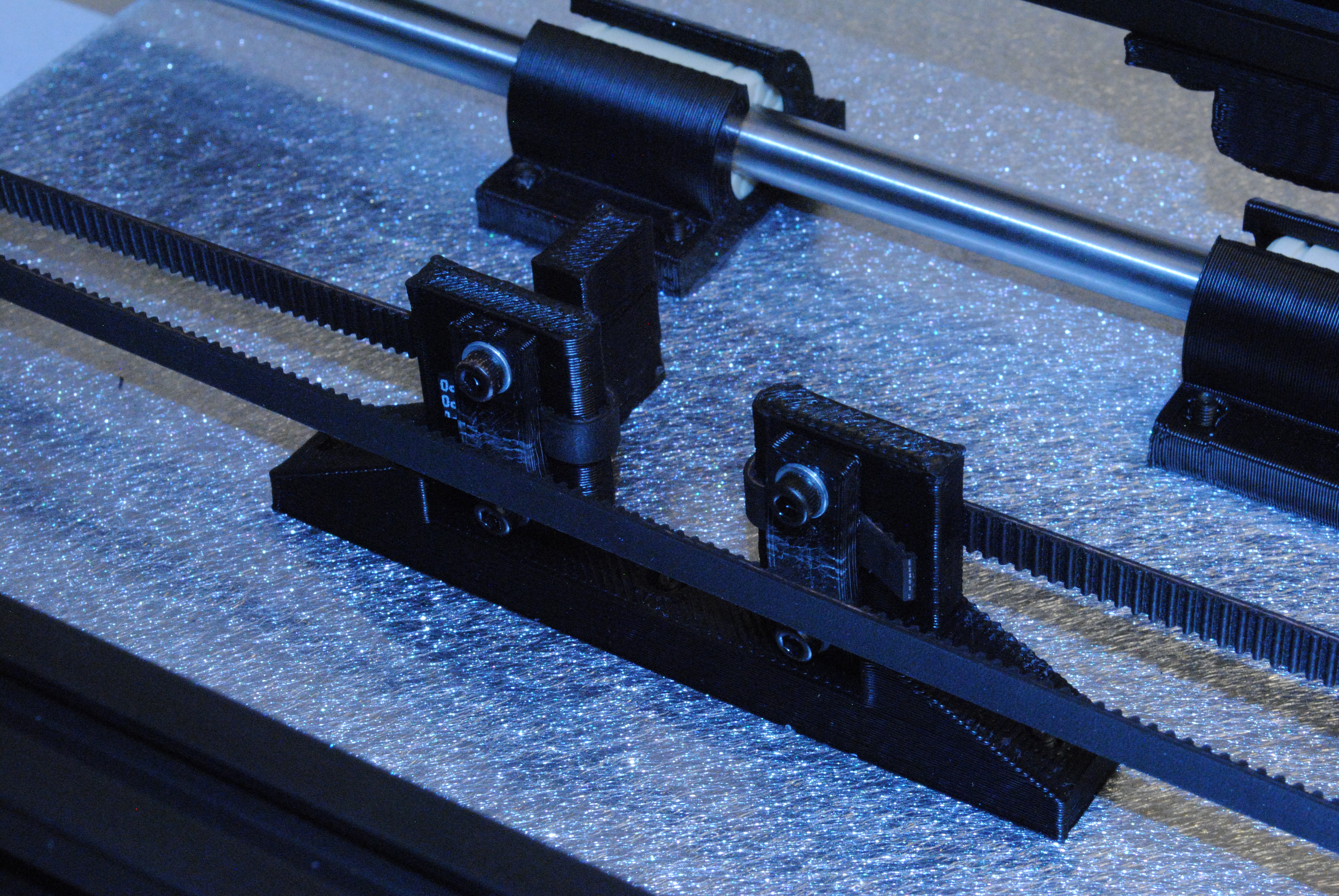
Install both belt clamps on the Y belt mount as shown using 2x M3 x 12 SHCS and M3 Washers on each. Keep these nice and loose at this point, you'll need to slide the belt under the clamp.
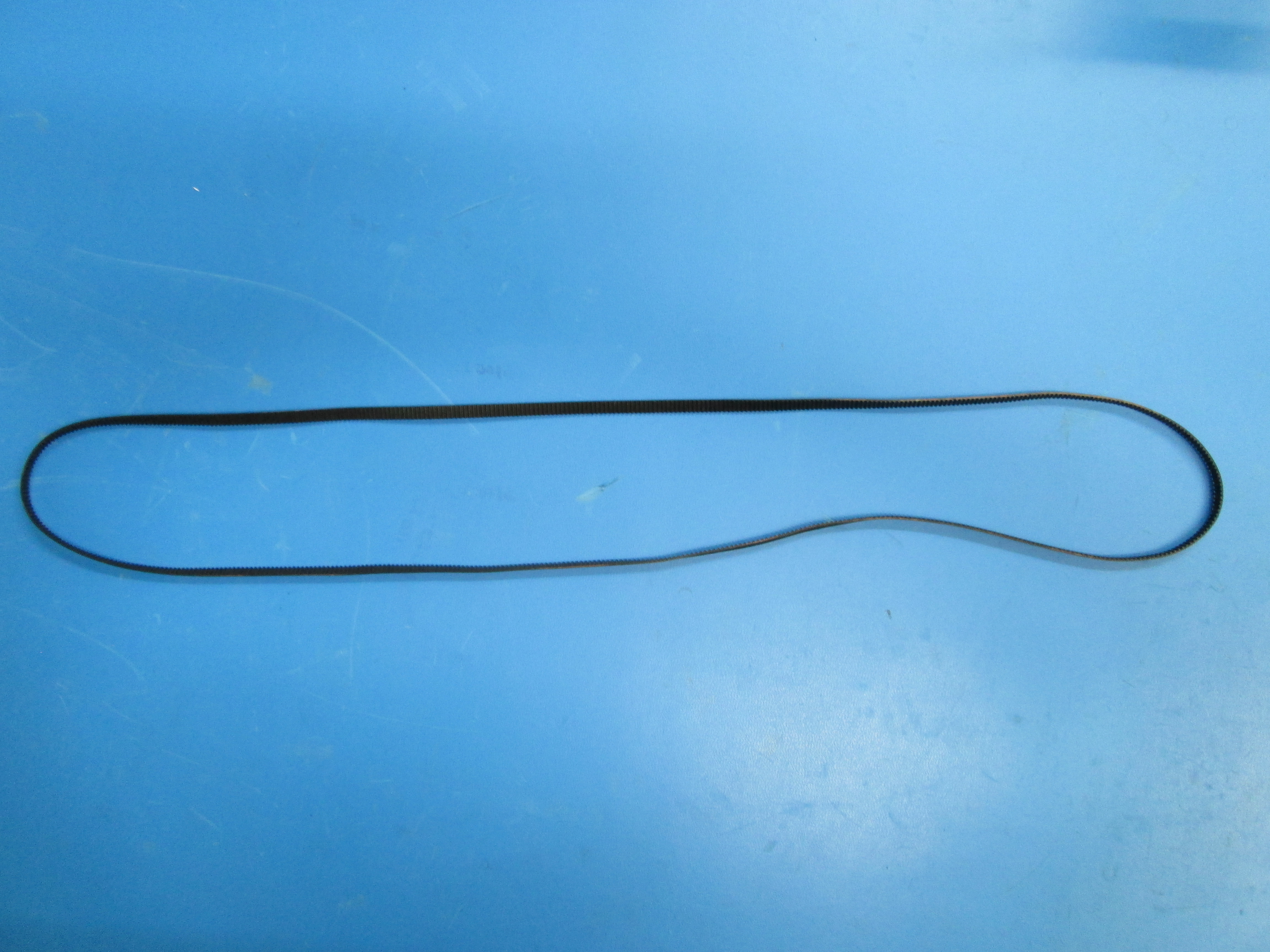
Cut the belt with a side cutter.
Clamp down the first end of the belt routing it as shown.
While pulling the belt tight, tighten down the second end of the belt.
Adjust the pulley on the Y motor up or down to get the belt the same height as where it's clamped on the Y belt mount.
Check if the belt is rubbing the Y end Idler by the bearings. If it is, adjust where the belt is in the clamp to raise it up a little.
Trim off the ends of the belt short enough they don't rub the belt when the plate assembly is moved back and forth.

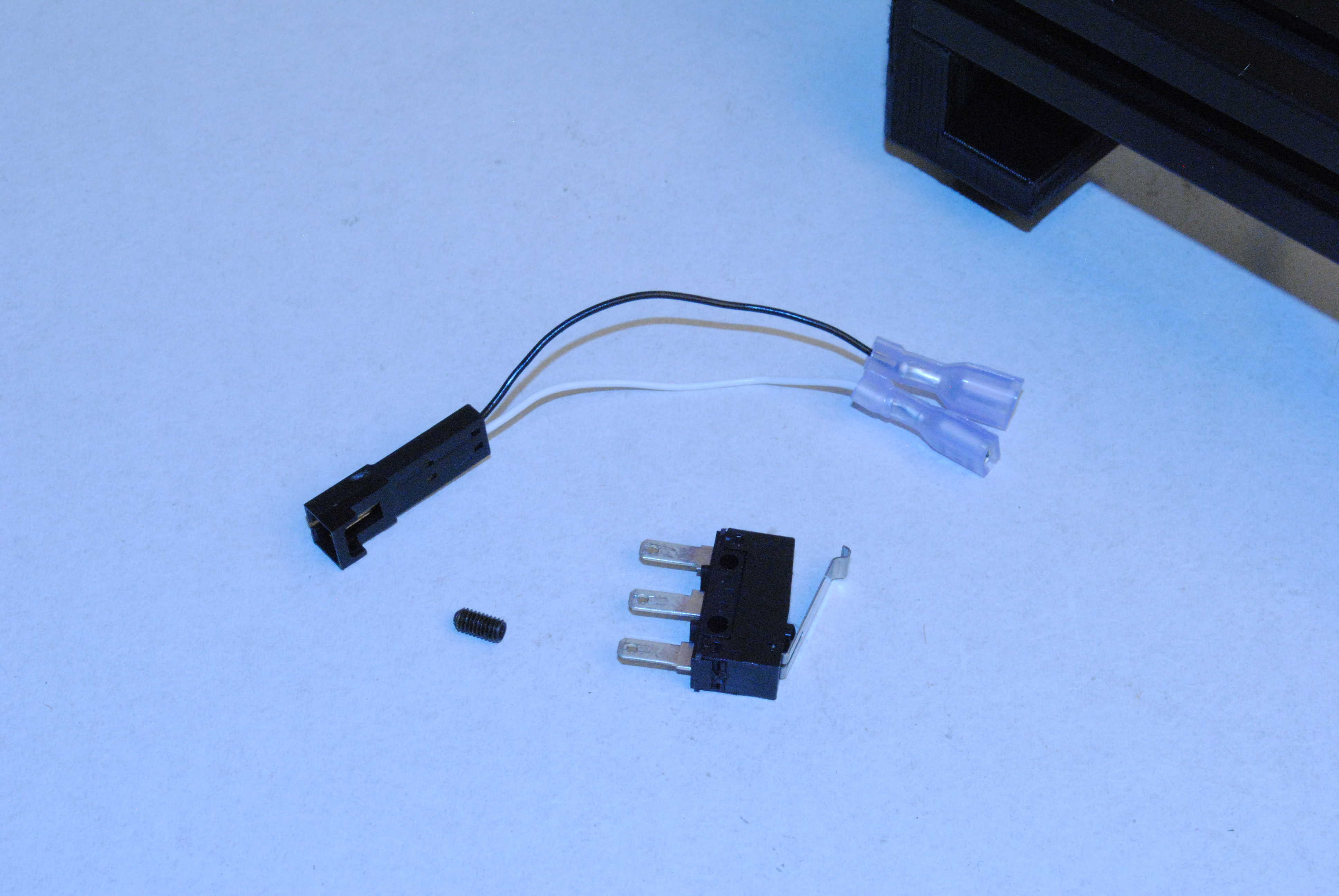
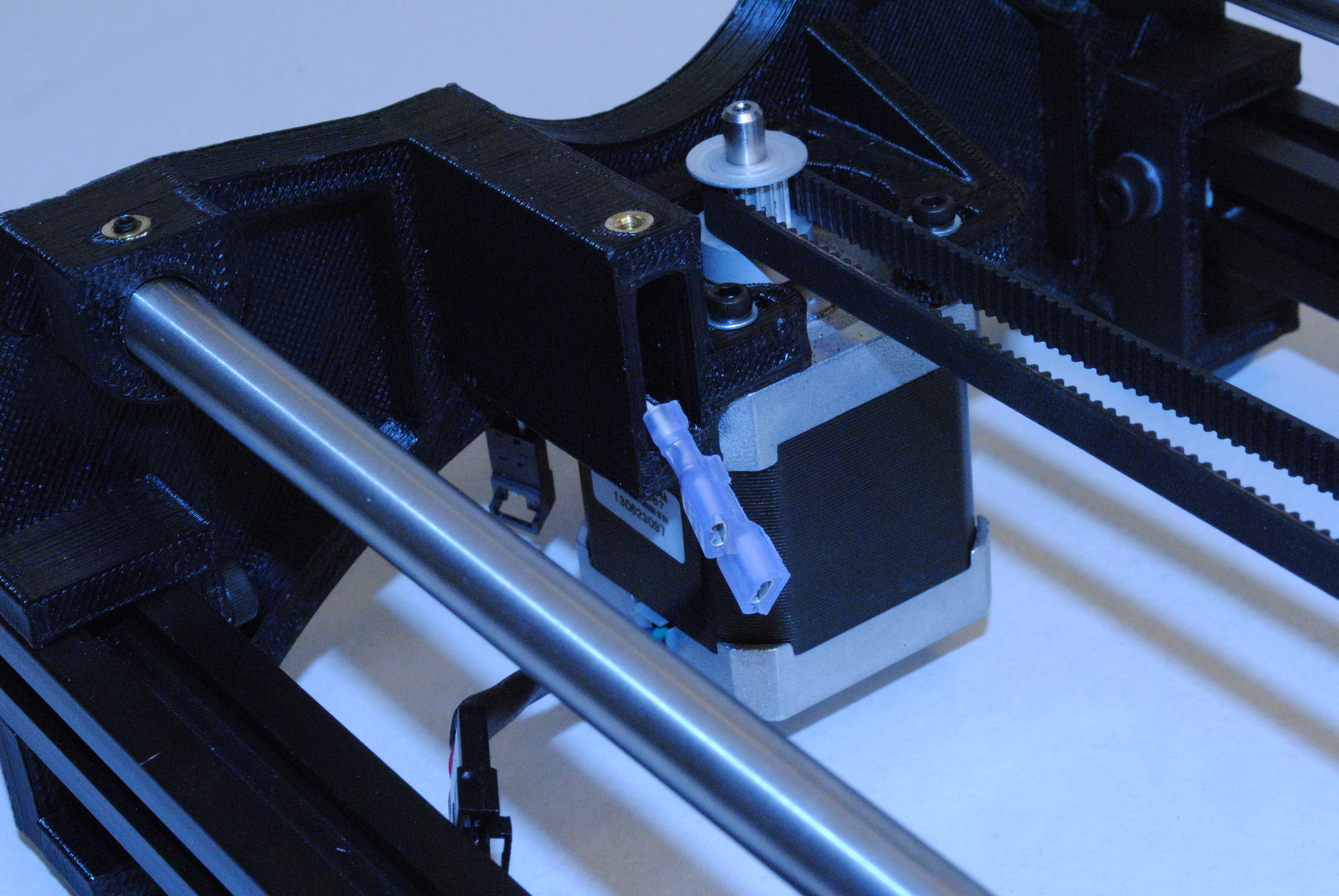
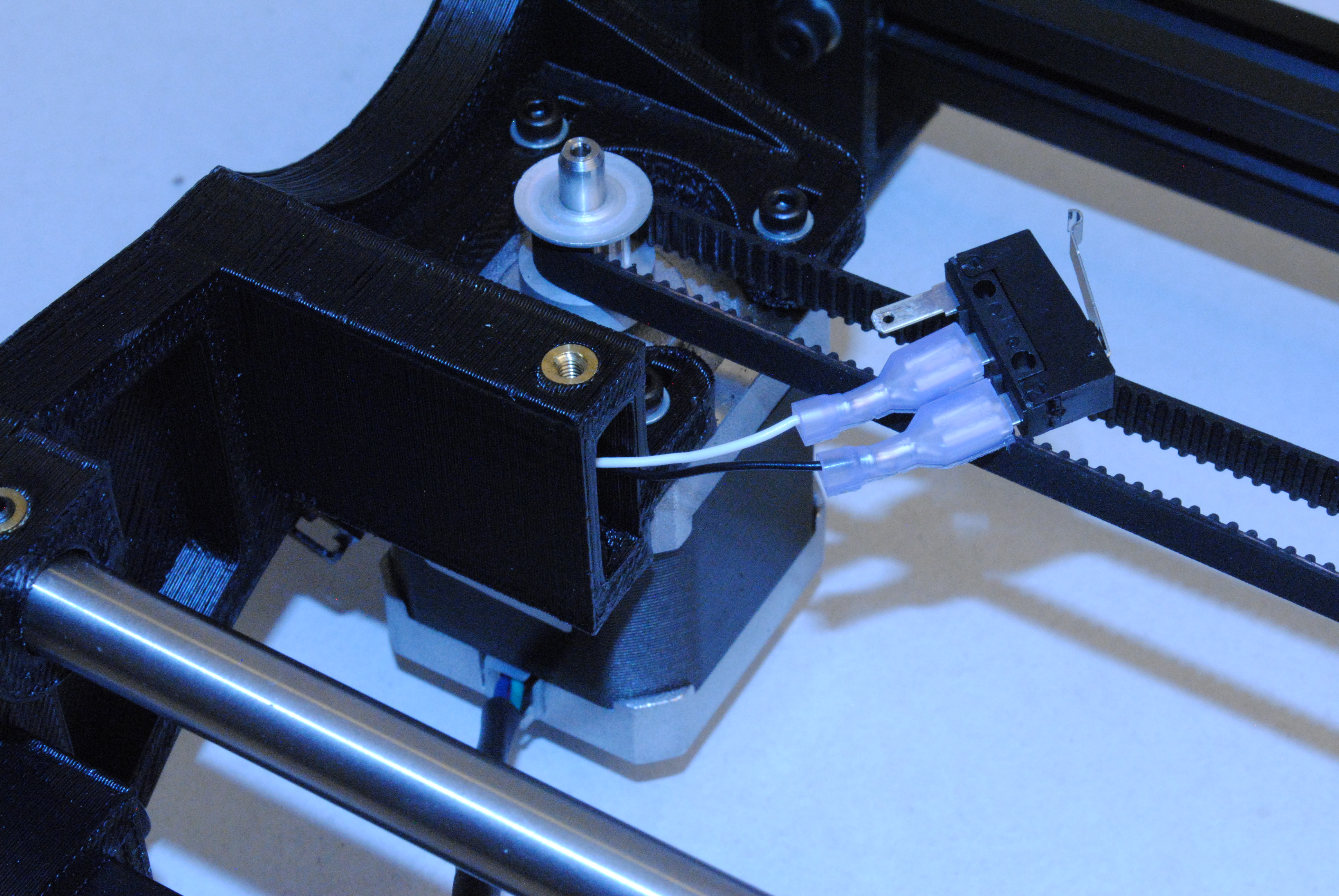
Slide the end of the Y switch extension with the quick connects on it up and into the Y end Motor.
Connect the white wire to the center terminal of the switch. (Normally Open)
Connect the black wire to the back terminal of the switch. (Common)
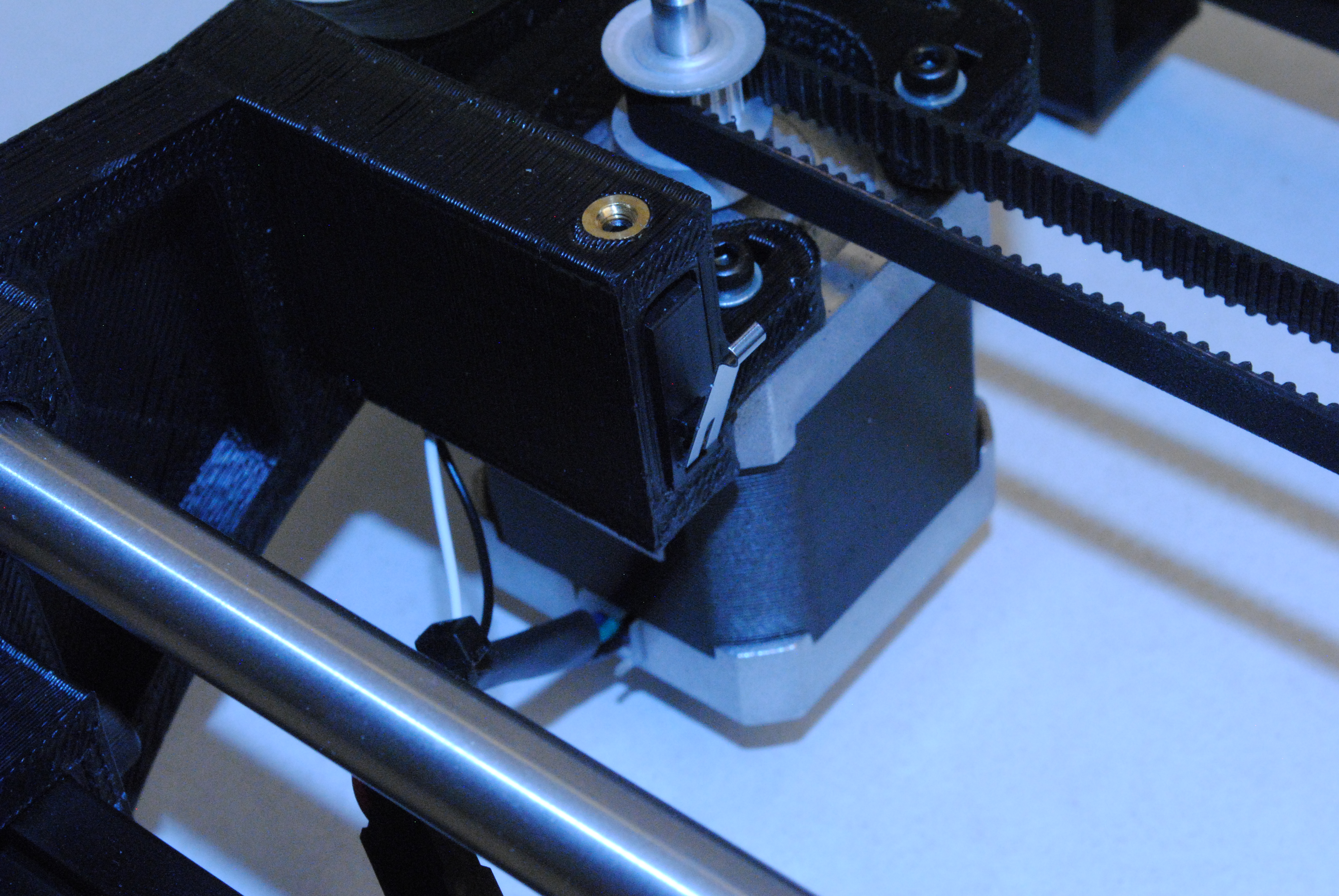
Slide the switch back into the Y end with switch arm extended upwards.
Leaving the switch slightly above the surface secure in place with a M3 x 6 set screw.
* Be very careful not to damage the switch with the set screw!
Zip tie the switch wire to the motor wire.