Open HardwareAssembly Instructions
Guides for installation and assembly of the LulzBot line of products made by FAME 3D LLC.
Guides for installation and assembly of the LulzBot line of products made by FAME 3D LLC.
Components
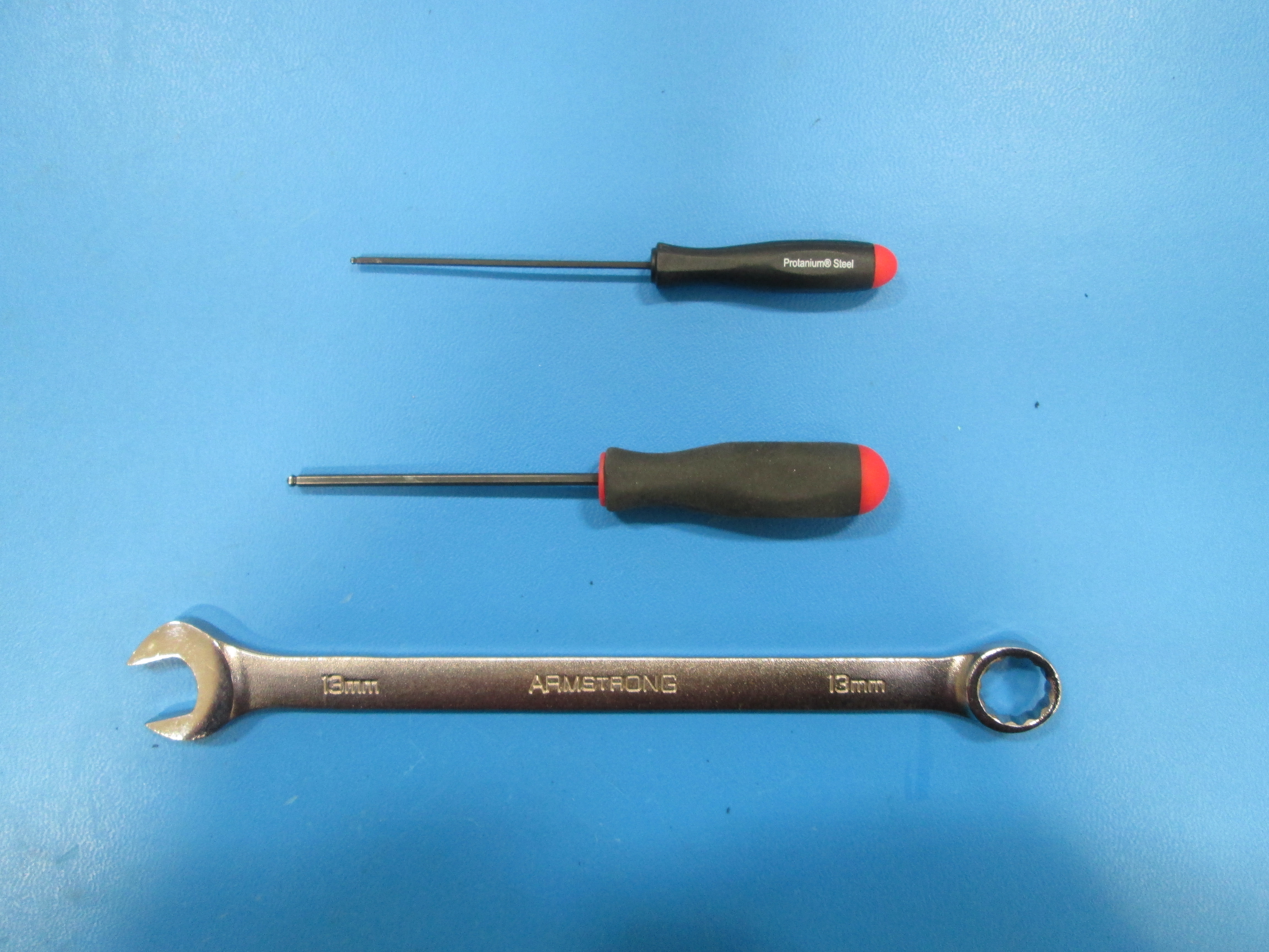
Tools
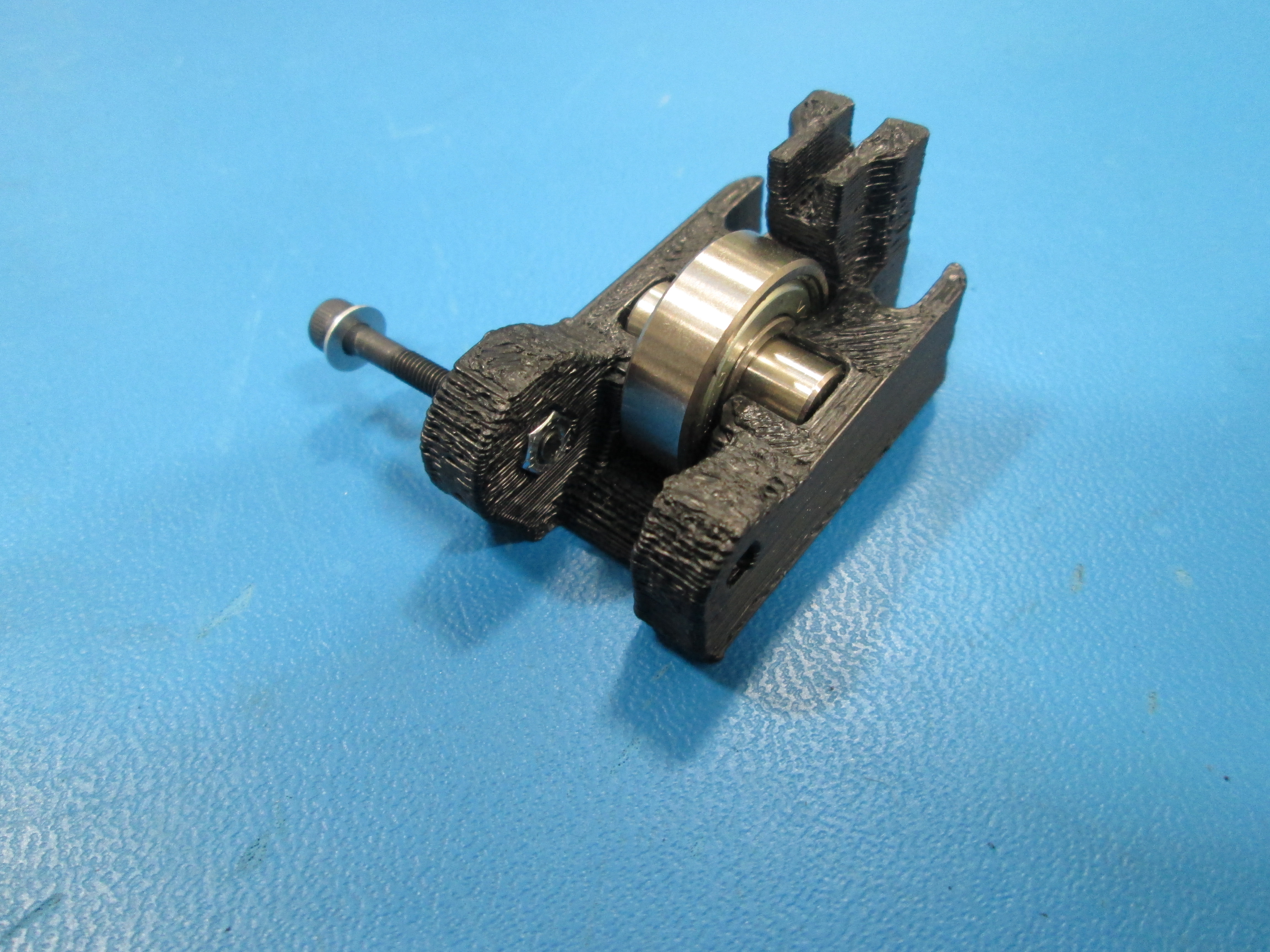
Install M3 x 25 SHCS, M3 Washer and M3 Nut into the Idler assembly. Only put the screw in till the tip is flush with the nut.
Tip: Set M3 Nut into hexagon cutout and hold with your finger to install the bolt.
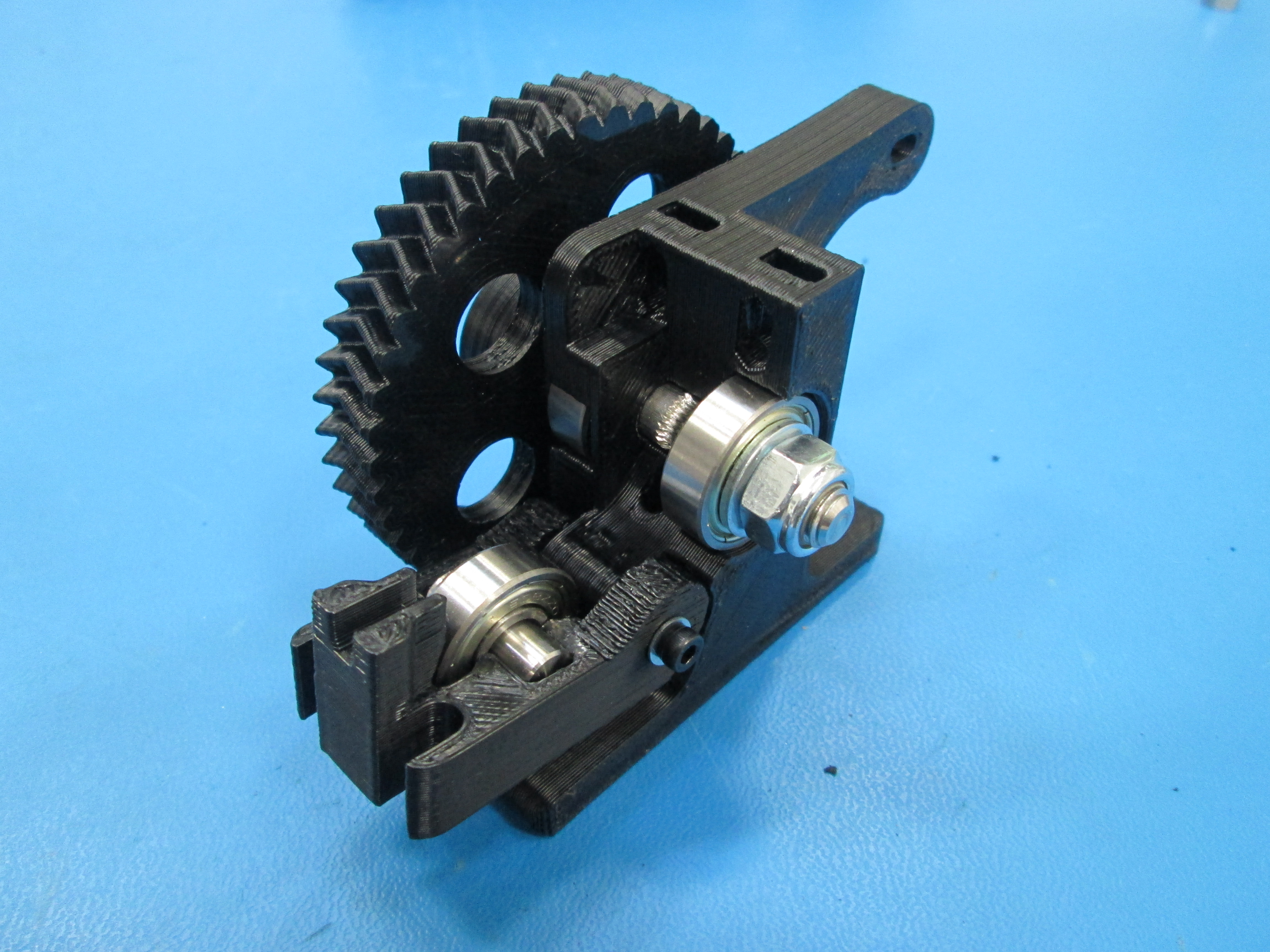
If needed, insert 8mm smooth rod into 608 bearing and press them into the idler block. This may require force. You can use a pair of pliers covered to prevent damaging the parts to snap in the 608 bearing and 8mm shaft.
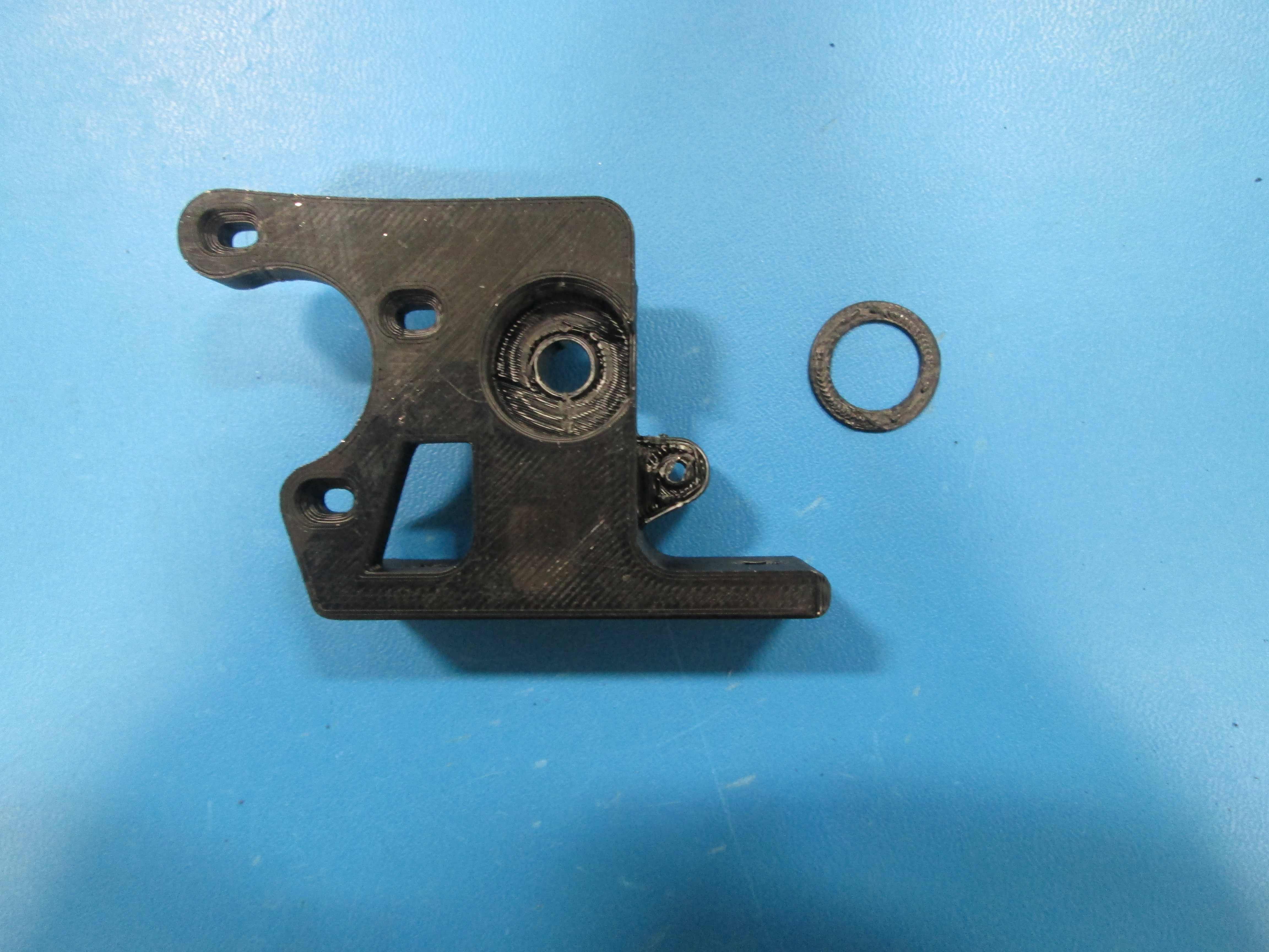
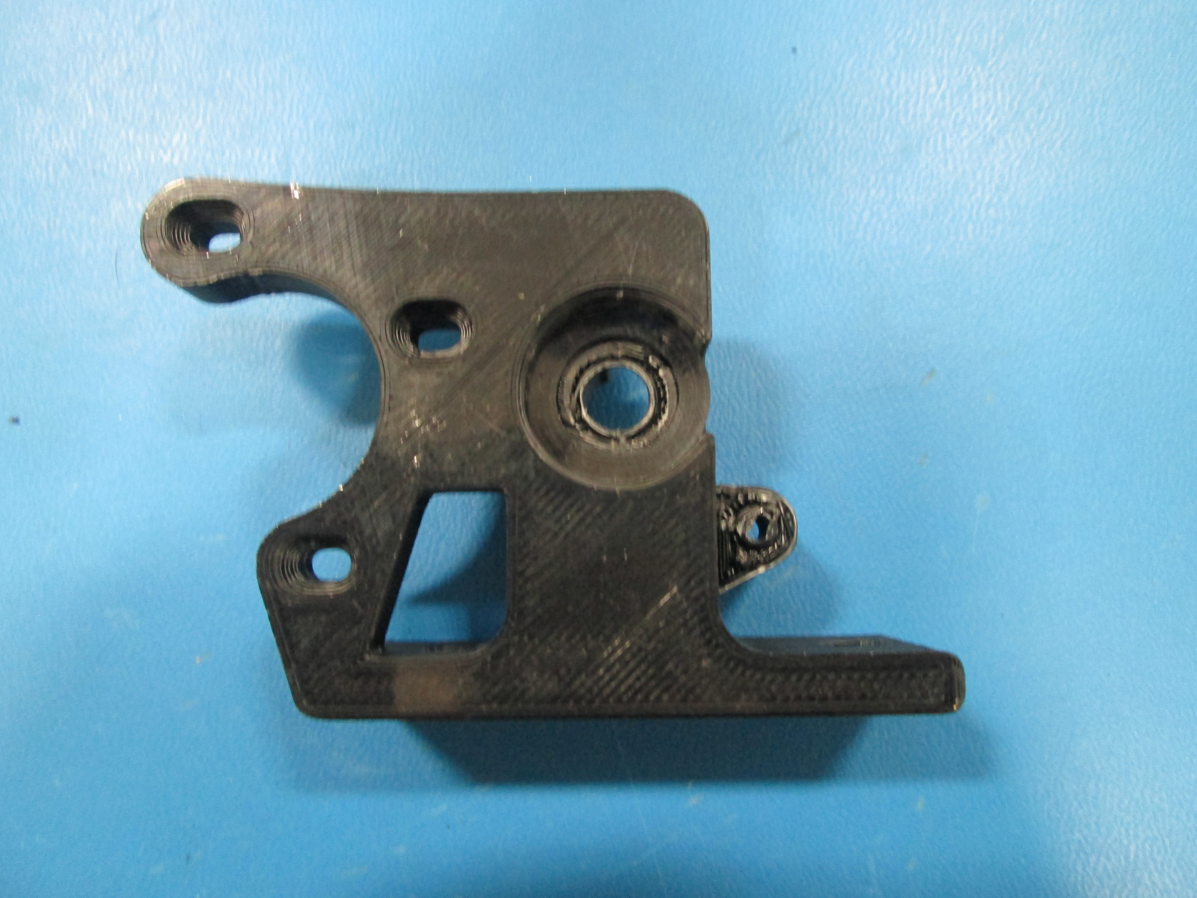
Place the printed extruder washer into the extruder body.
If needed, press hobbed bolt into large herringbone gear.
Install 1x M8 washer onto hobbed bolt then a 608 bearing.
Once installed, does the hobbing on the bolt line up with the small hole going thru the extruder body?
If you need to adjust it's location, you can add either a 0.50mm or 1.0mm shim washer to get the correct spacing.
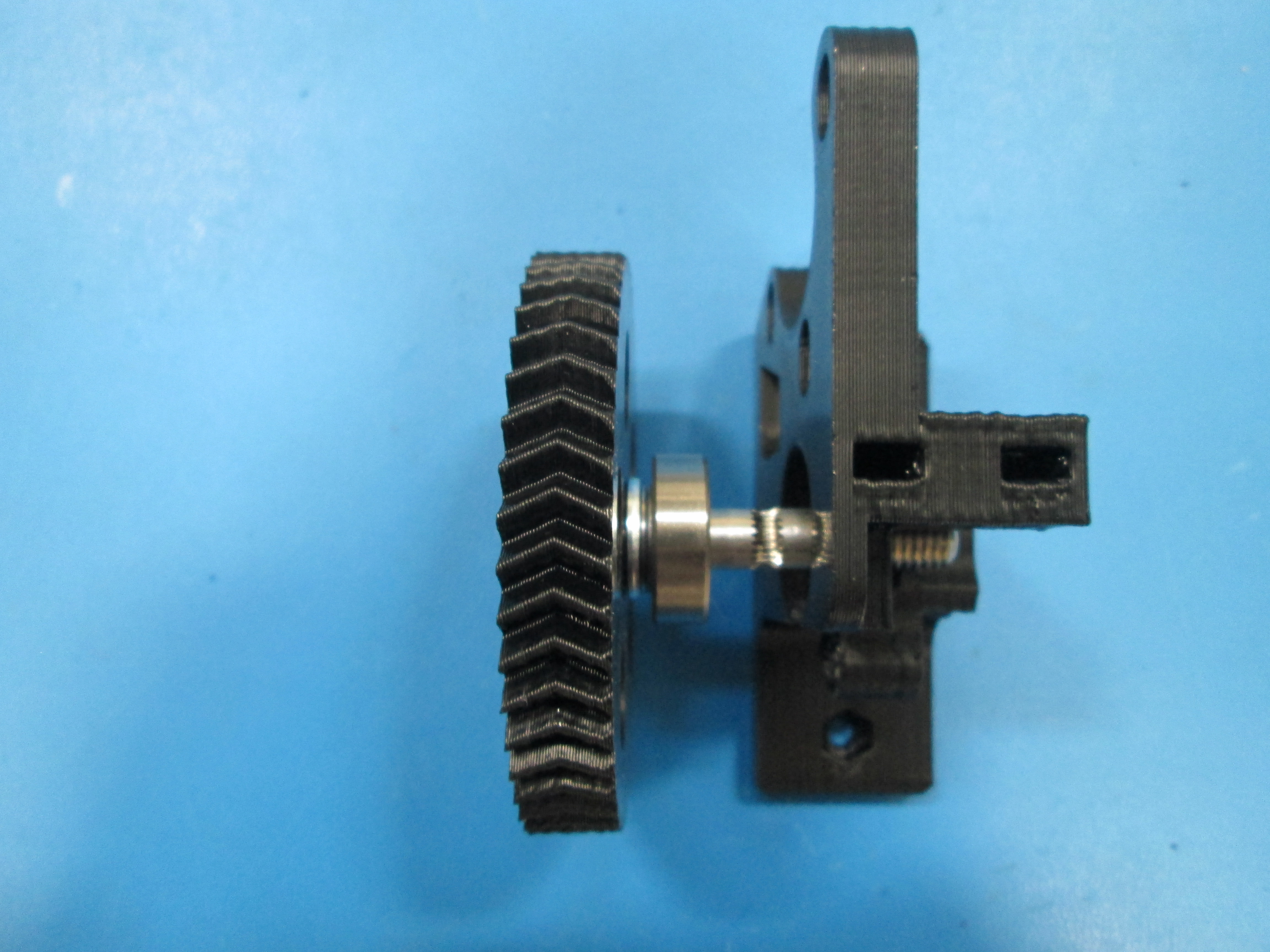

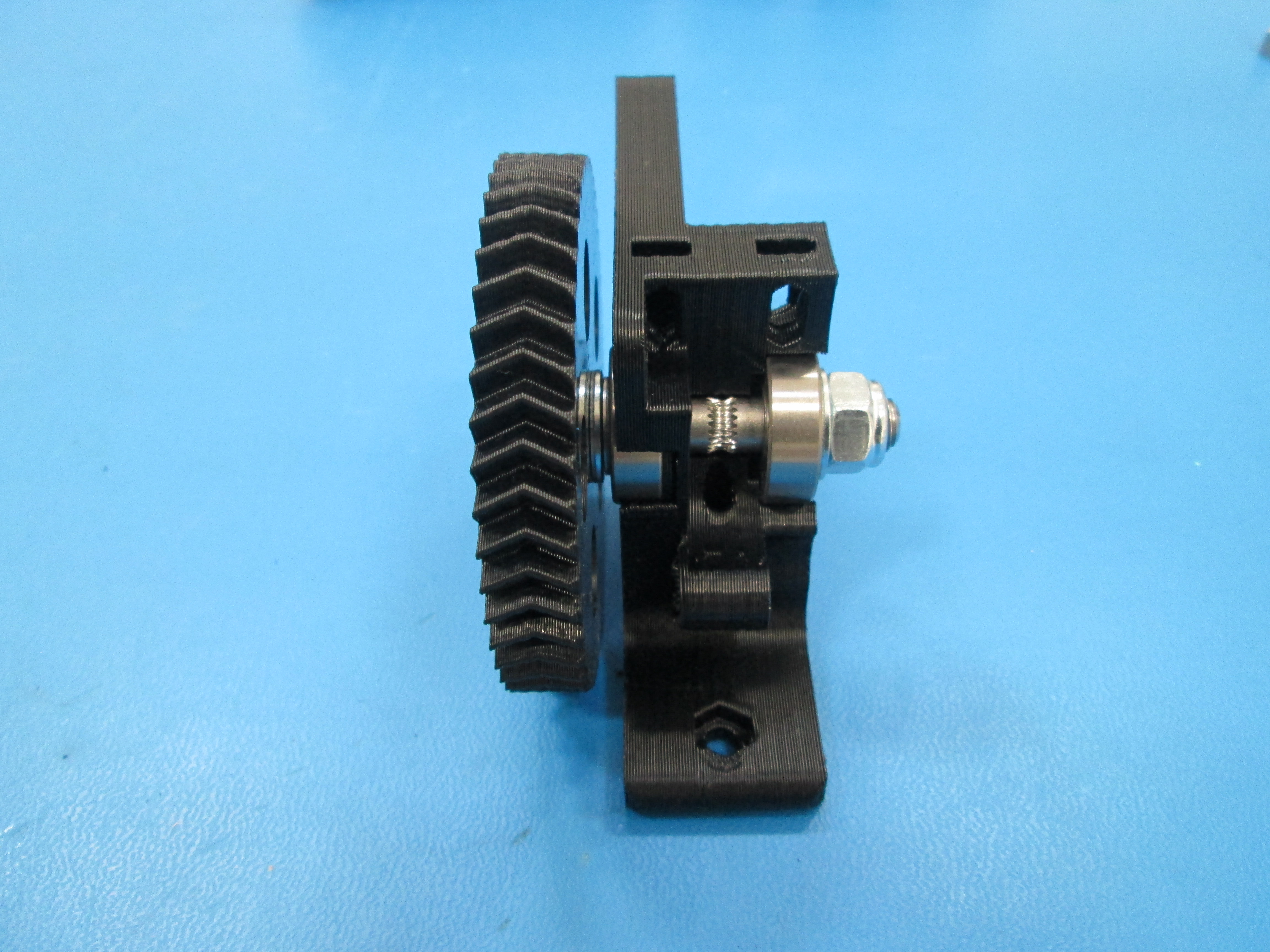
On the opposite side of the gear, add a 608 bearing, M8 Washer and a M8 nyloc nut.
Tighten the Locknut down until the bearing is seated and there is no space between the Nut, Washer and Bearing.
You may need to go back and add or subtract a 1mm shim washer or .5mm shim washer.
The large gear shouldn't be able to rock back and fourth, but should spin freely.
Install extruder idler onto the body.
Tighten the M3 x 25, SHCS bolt down to secure the Idler.
Tip: Place the leg with the nut on the body first and twist the Idler onto the body.
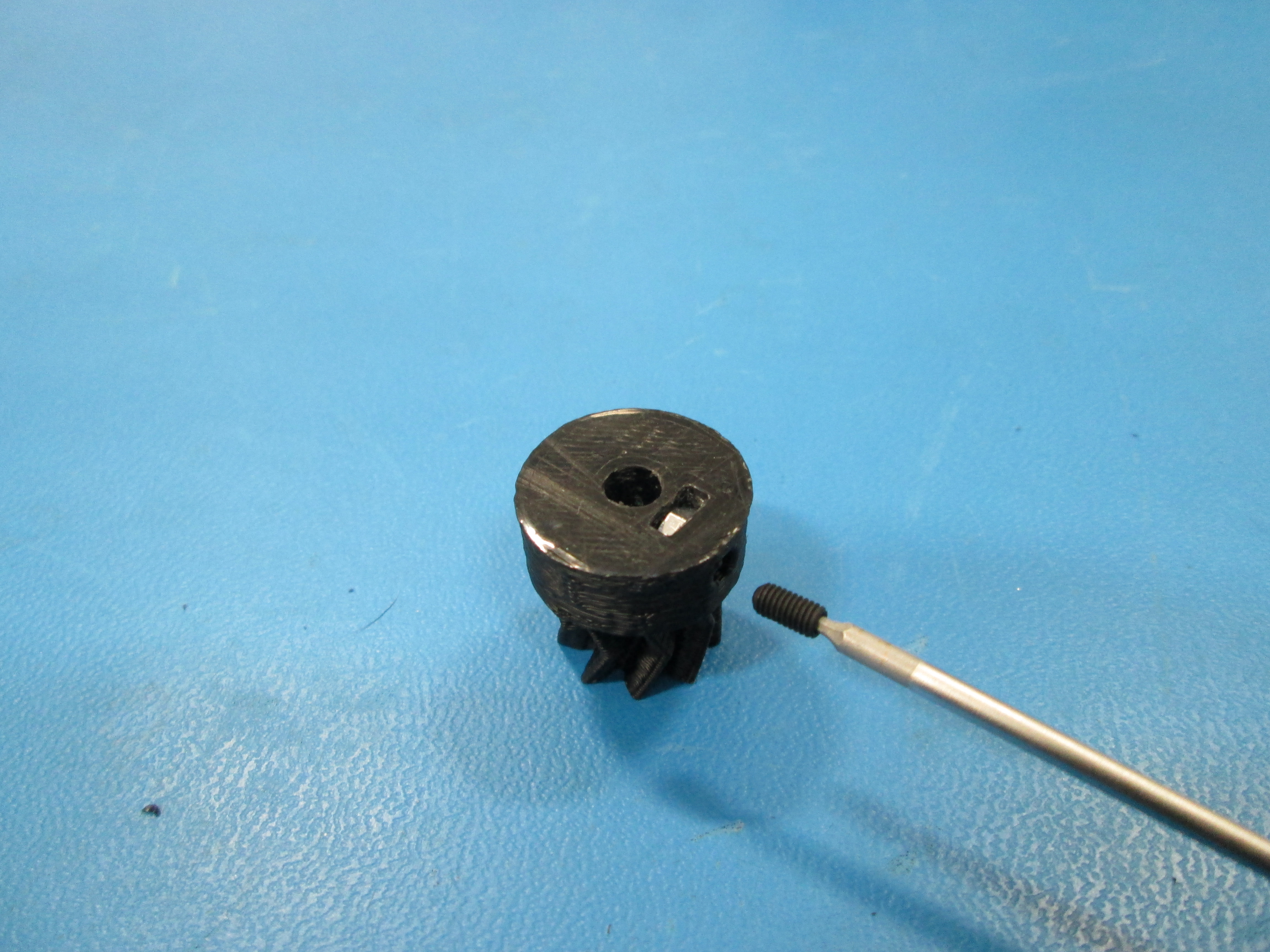
Install the M3 nut into the bottom of the small herringbone gear.
Then install the M3 x 6mm set screw through the side of the small gear and into the nut.
Be sure the M3 x 6mm set screw does not protrude into the hole through the small gear.

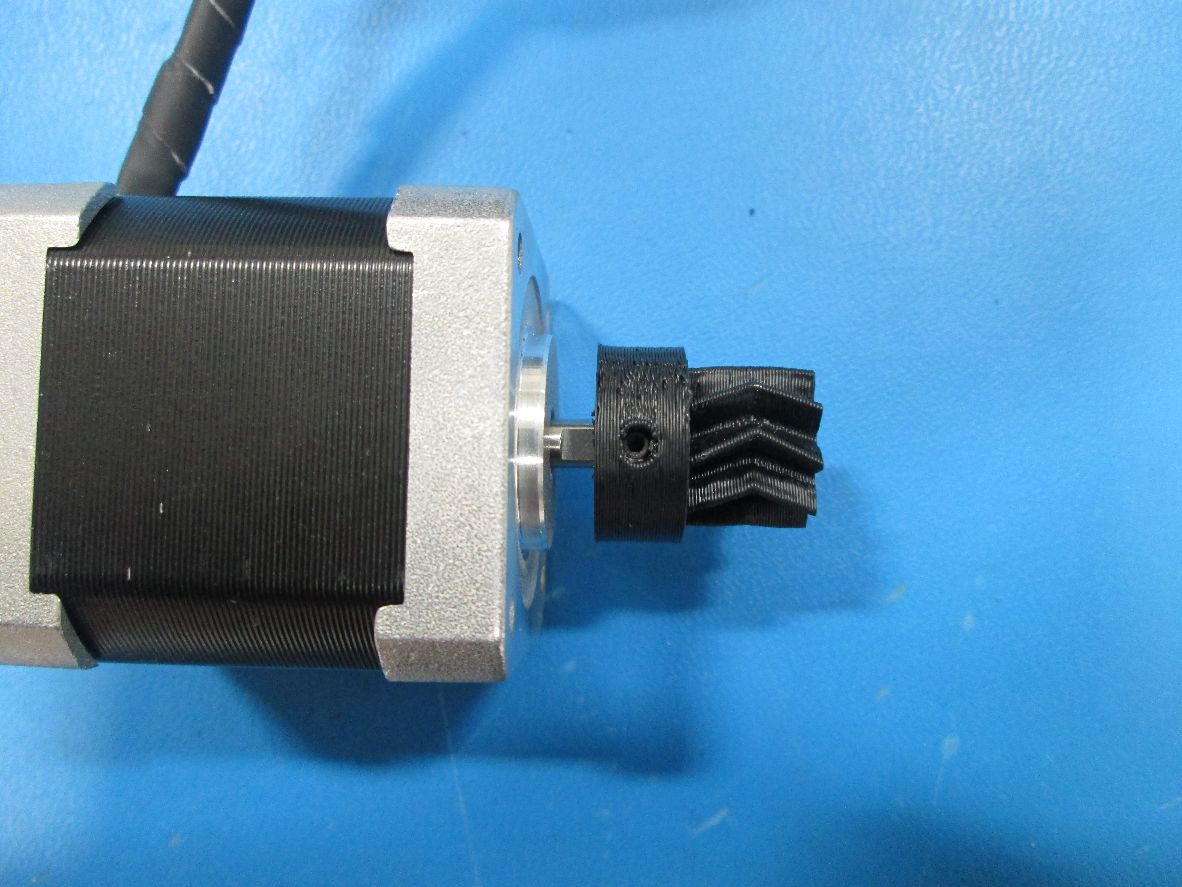
Locate the flat side of the motor shaft.
With the set screw aligned with the flat, slide the small gear onto the motor shaft.
The location will be adjusted later so positioning isn't important at this point.
Do not tighten the set screw yet.
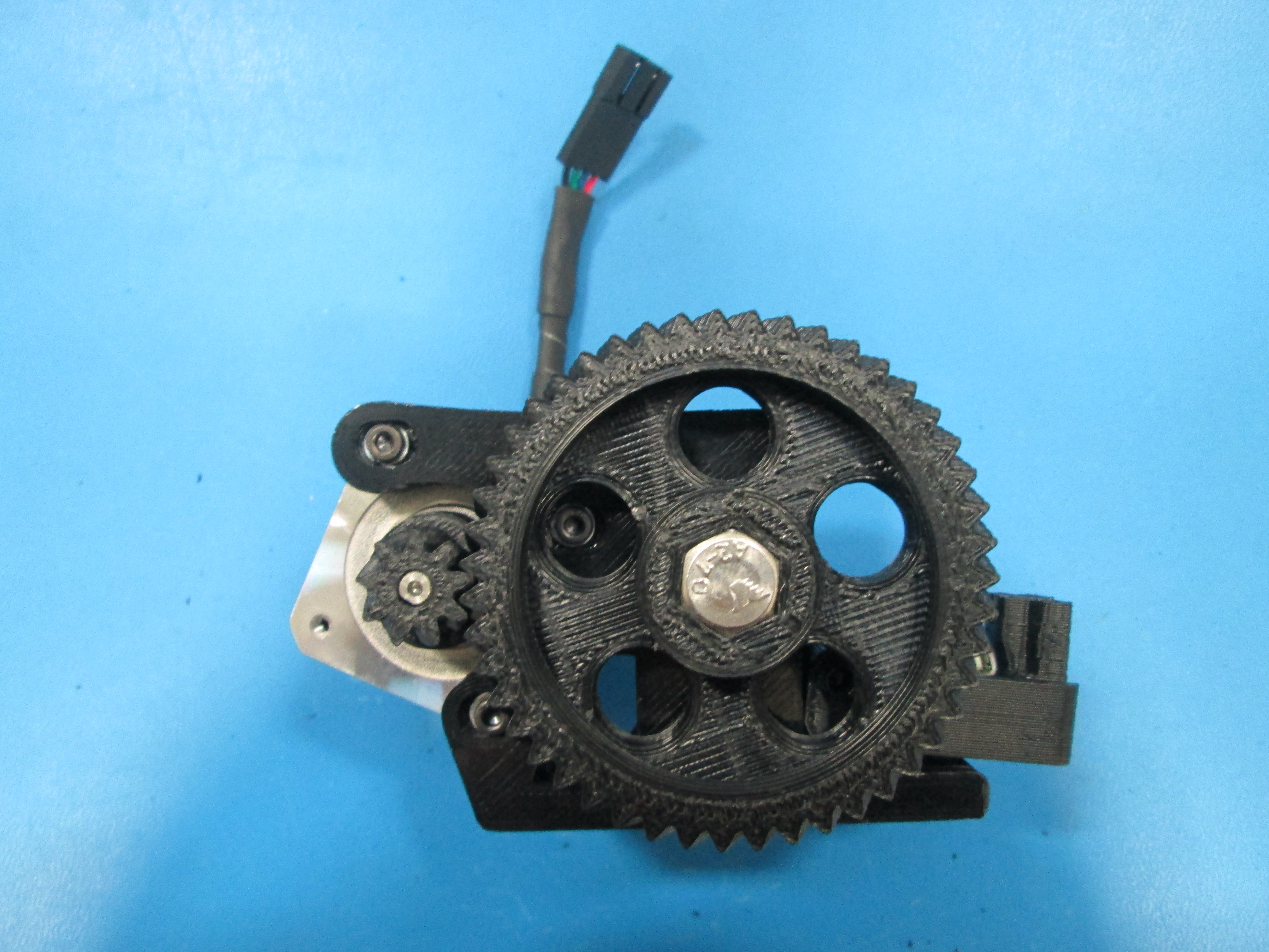
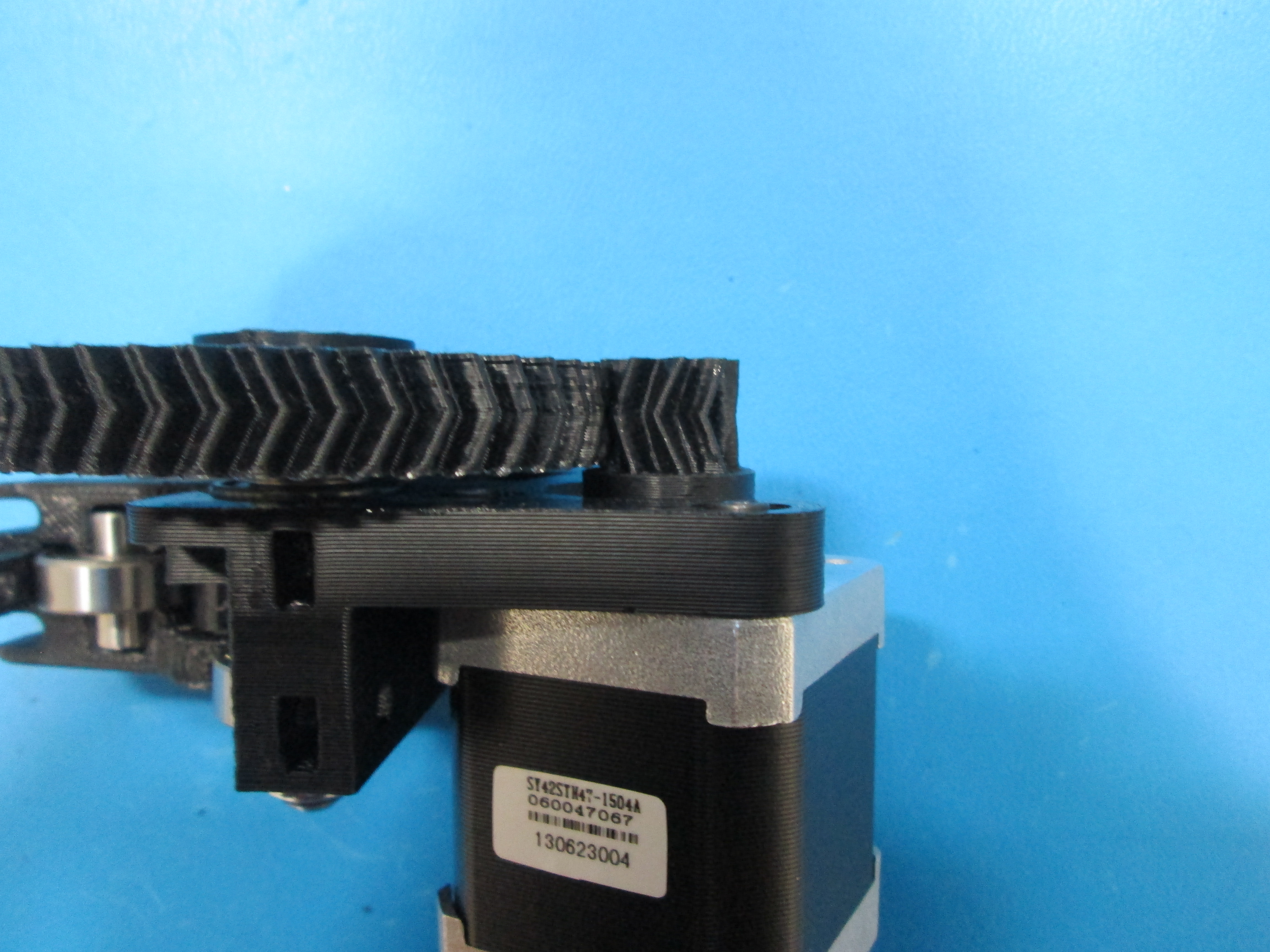
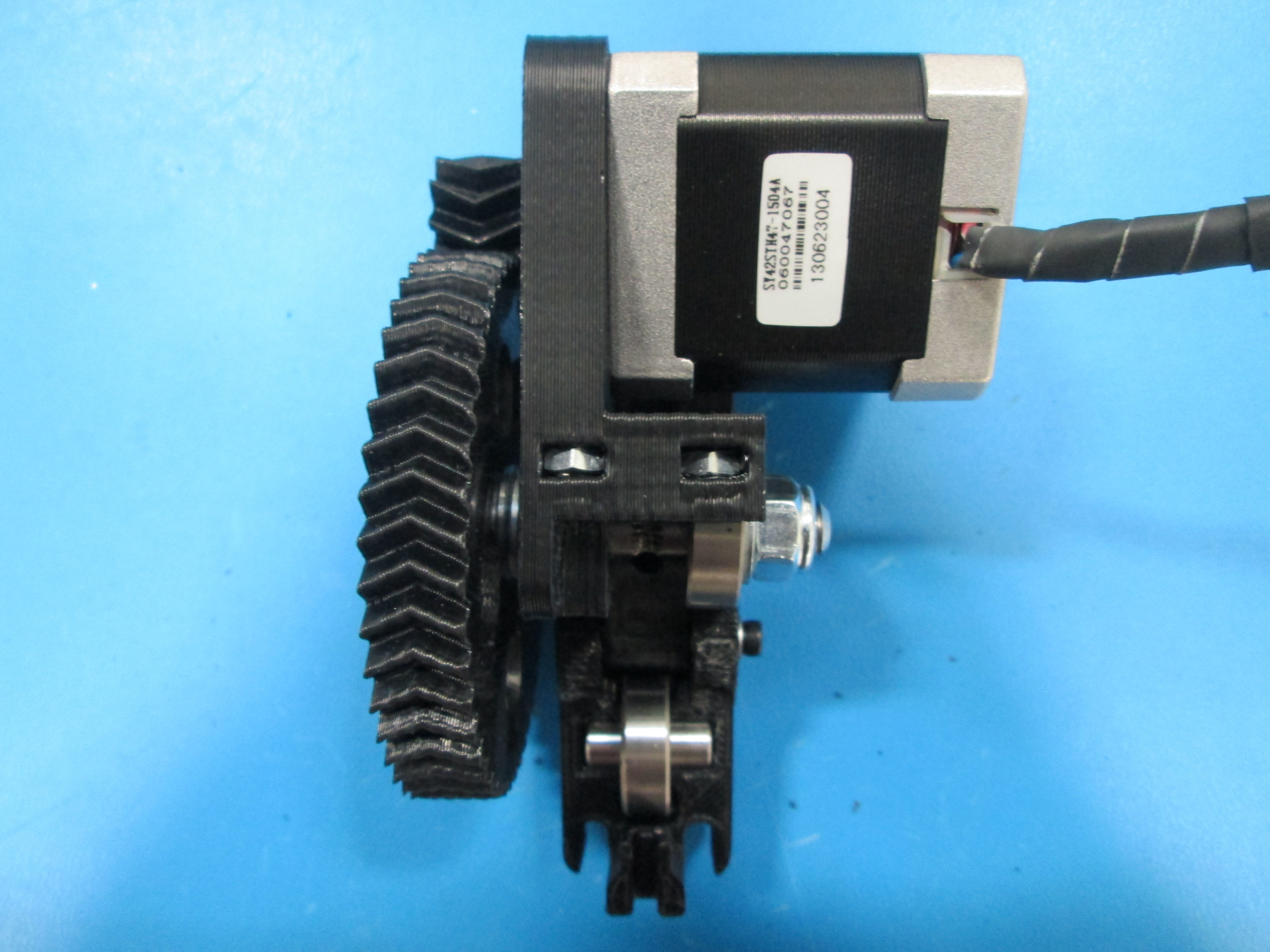
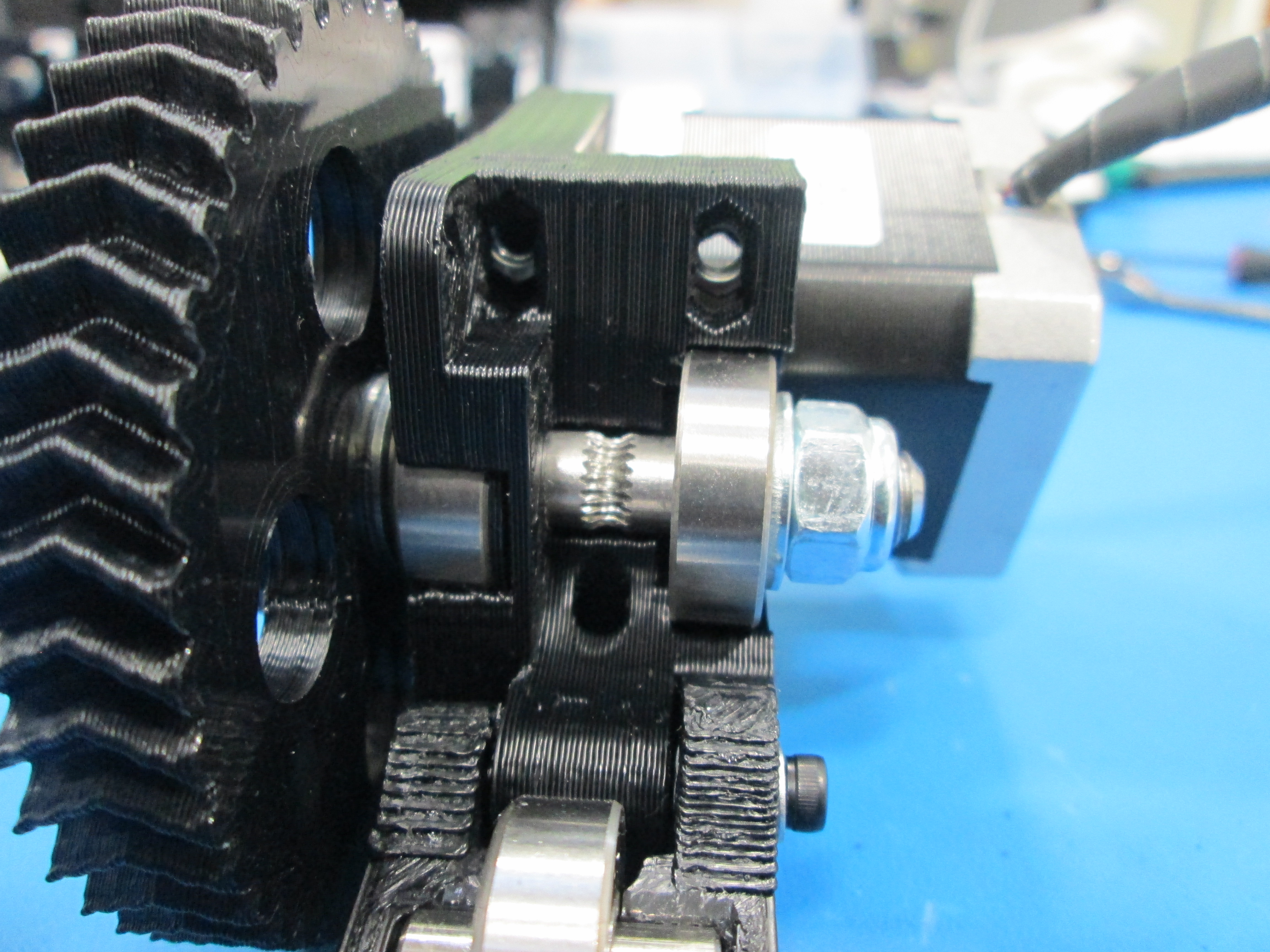
Holding the motor in the location where it will be mounted, align the herringbone gears by sliding the small gear in or out on the motor shaft so the V-grooves are centered on each other.
Install motor using 3x M3x12 SHCS and 3x M3 washers, taking note of the orientation of the motor wires.
Push the gears together while you tighten the bolts to make sure the contact is tight.
Tighten the set screw on the small herring bone gear.
There shouldn't be any backlash in the gears.
Install 2x M4 nuts into the top of the extruder body as shown.
Make sure you can see the nuts from the side so you can install bolts later.
Tip: Nuts only go in one way, the flats of the nut must be vertical.
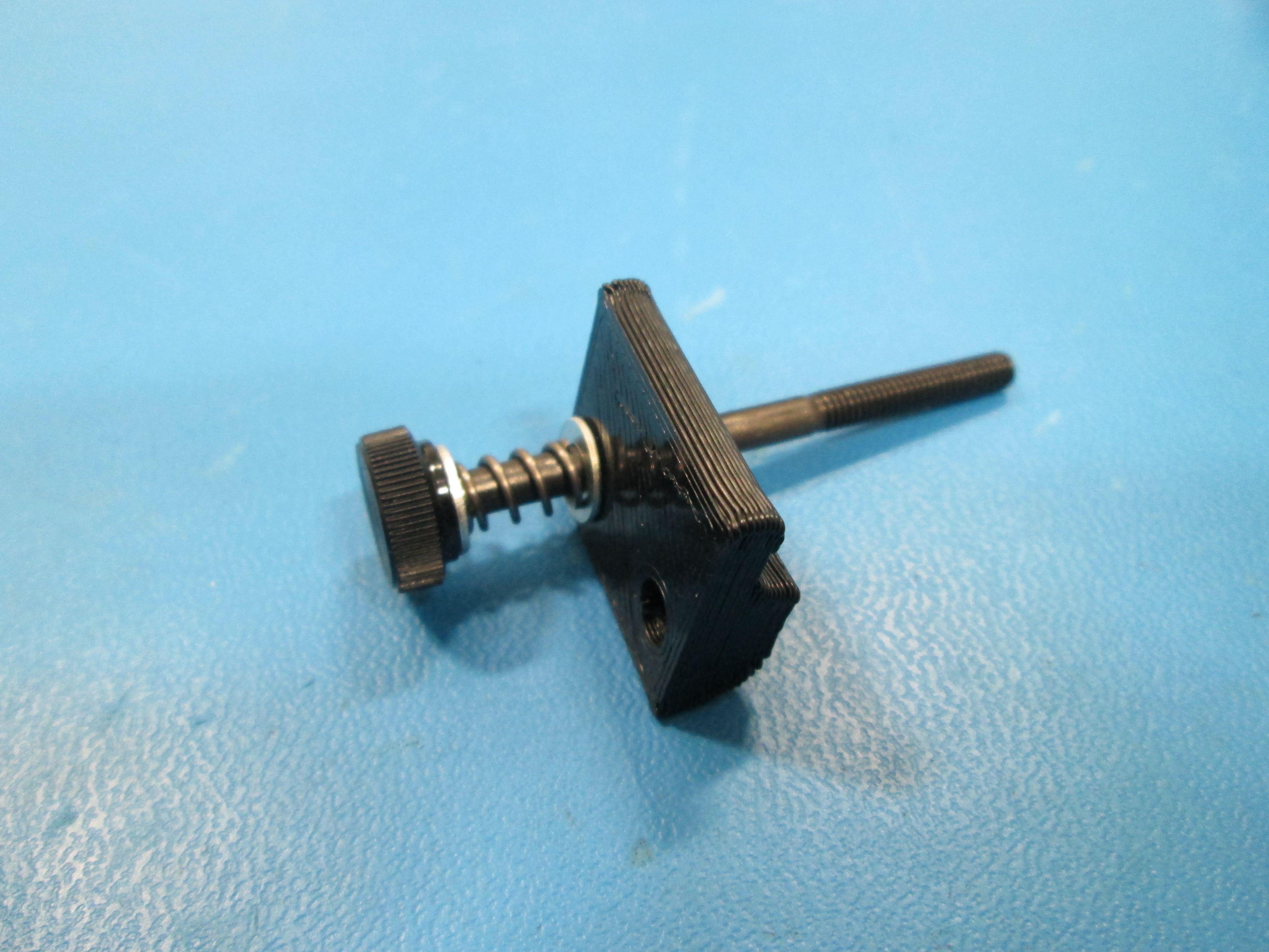
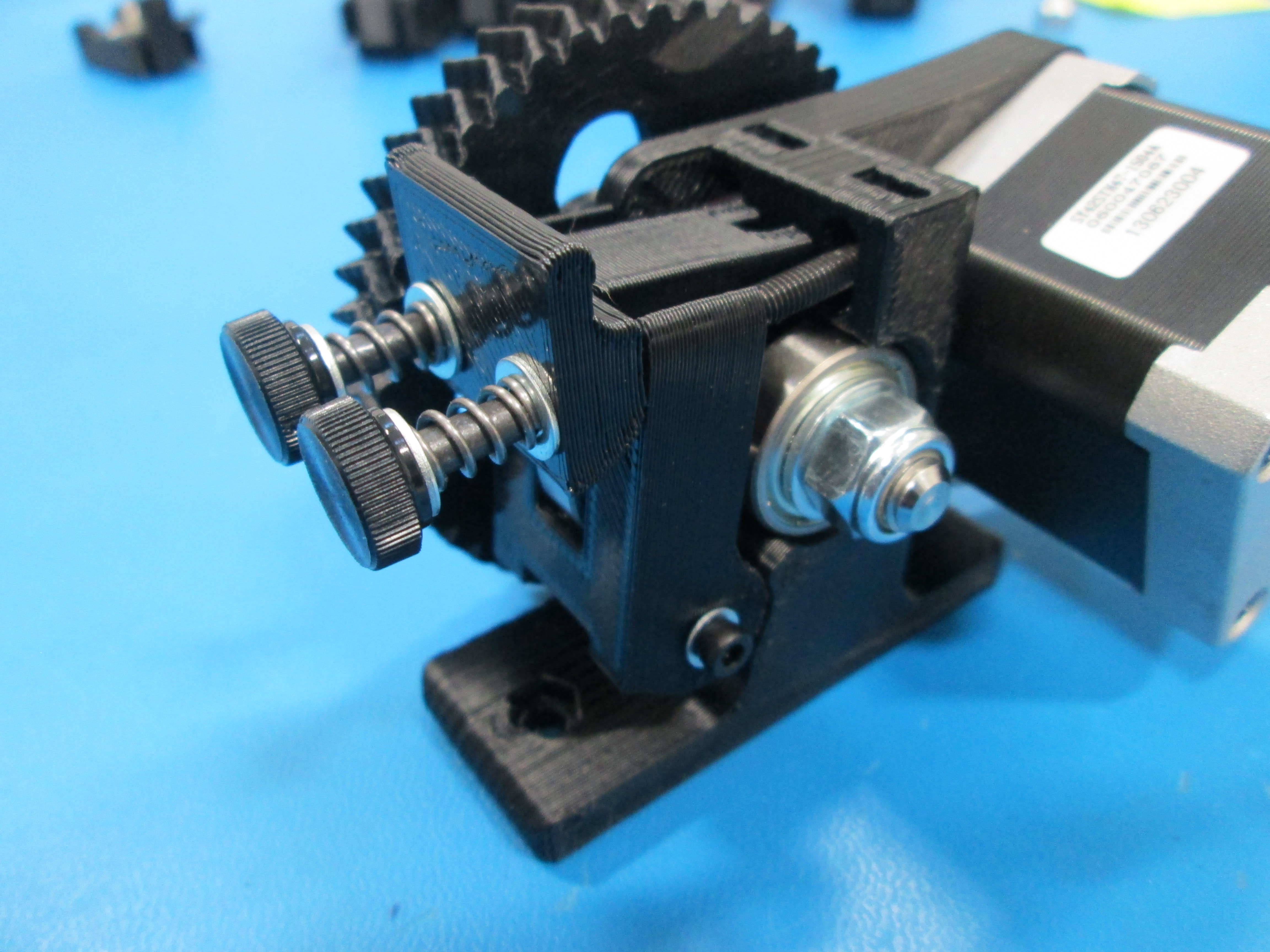
Install M4x55 thumb screw, M4 washer, extruder spring, M4 washer and Extruder latch into M4 nut installed in body.
Then put another M4 x 55 with thumb knob, M4 washer, extruder spring, M4 washer through the Extruder latch and into the body.
Make sure extruder latch is oriented correctly.
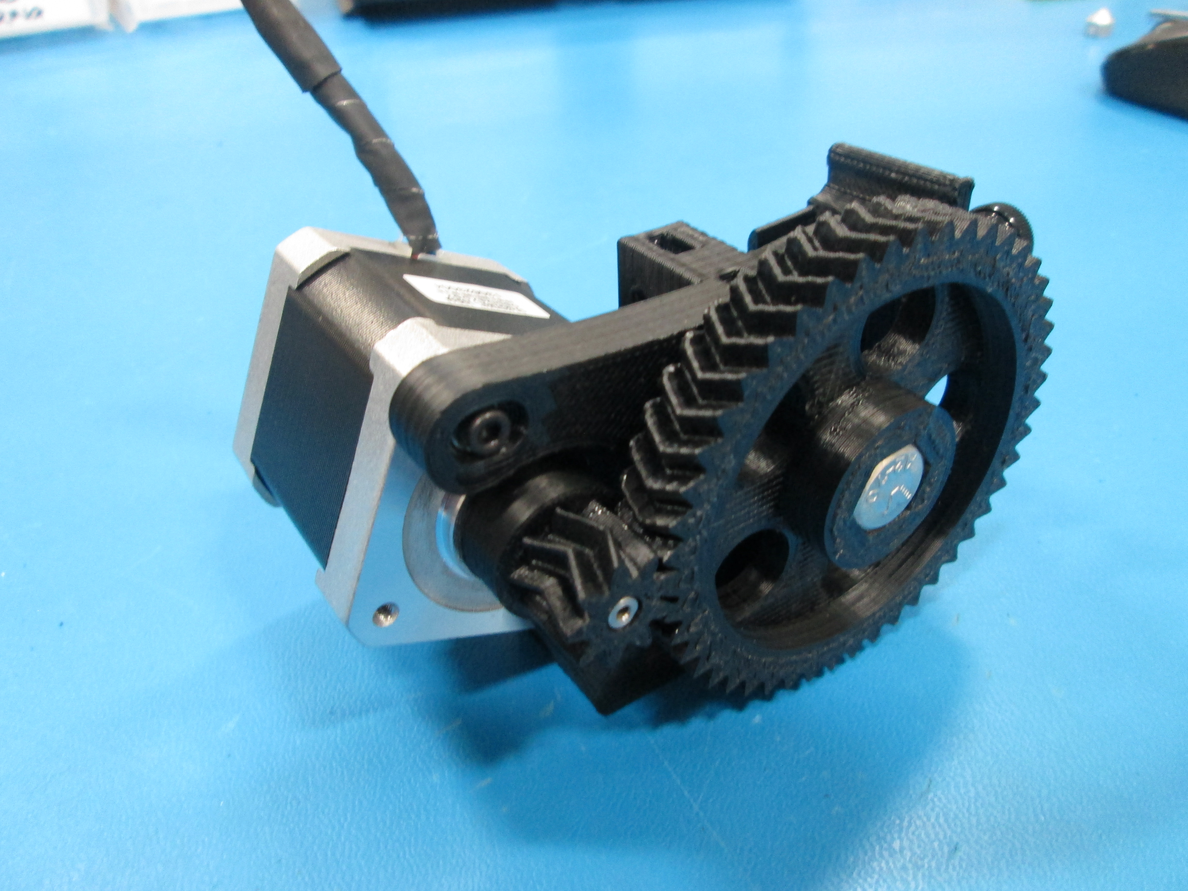
Review your assembly for workmanship.