Open HardwareAssembly Instructions
Guides for installation and assembly of the LulzBot line of products made by FAME 3D LLC.
Guides for installation and assembly of the LulzBot line of products made by FAME 3D LLC.
1x- [EL-HR0146] Bed Extension Harness
1x- [HD-BT0048] M5x10 SHCS
1x- [HD-BT0104] M3x8 BHCS SST
2x- [HD-BT0128] M3x6 FHCS Black-Oxide
2x- [HD-BT0140] M3x6 BHCS Black-Oxide
31x- [HD-BT0148] M3x10 BHCS
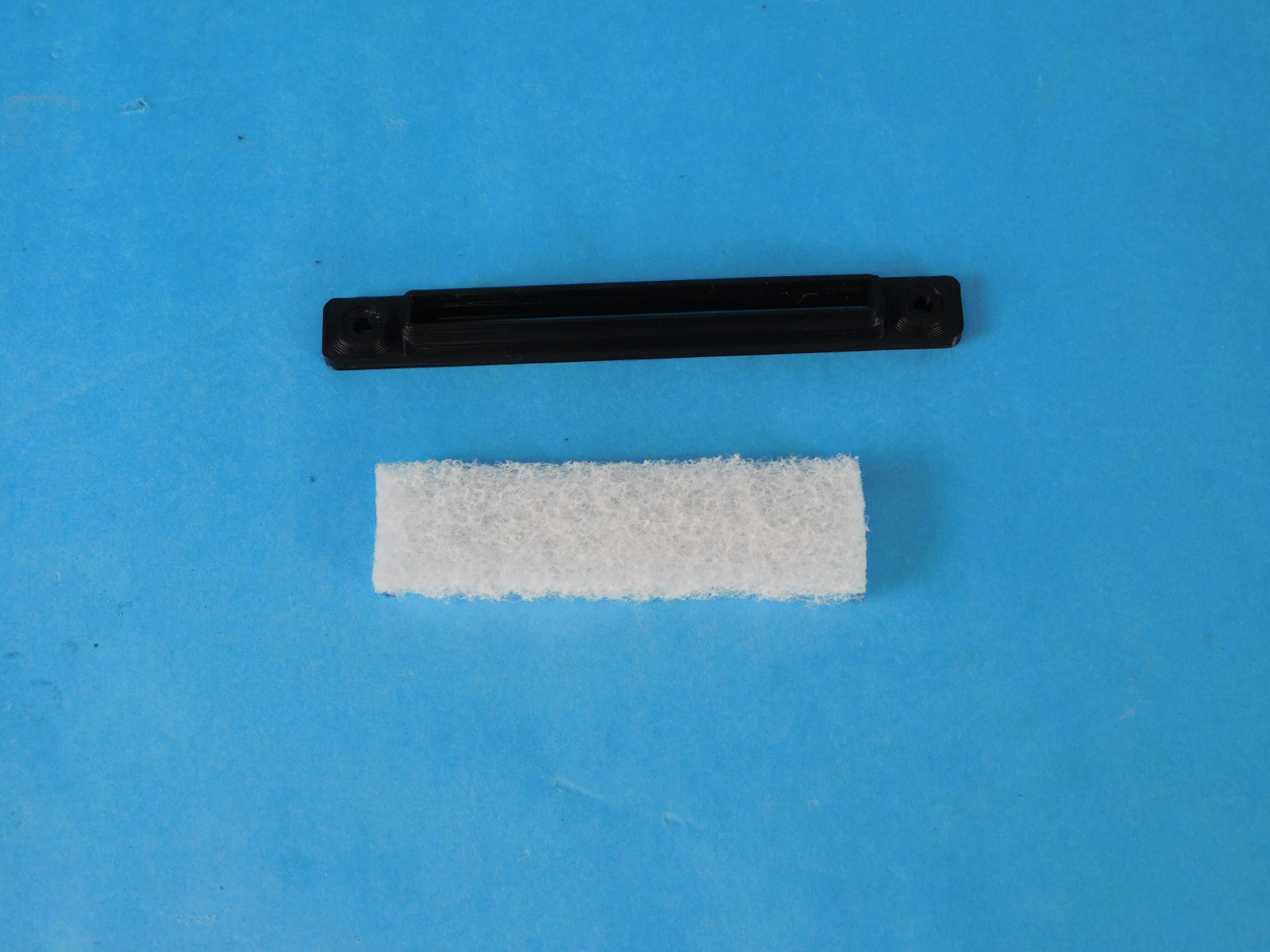
2x- [HD-MS0531] White Scotch Brite Cleansing Pad
1x- [HD-WA0035] External Serrated Lock Washer, M3 Screw Size
31x- [HD-WA0038] Black-Oxide M3 Washer
1x- [PP-GP0369] Y Belt Mount
2x- [PP-GP0381] Wiper Mount
1x- [PP-GP0391] Y Cable Cover
4x- [PP-GP0393] Y-Bearing Holder
4x- [PP-GP0477] Bed Corners
1x- [PP-GP0478] Flexible Heat Bed Standoff
1x- [PP-MP0216] Bed Plate, 6061
1x- [PP-MP0227] XY Calibration Cube
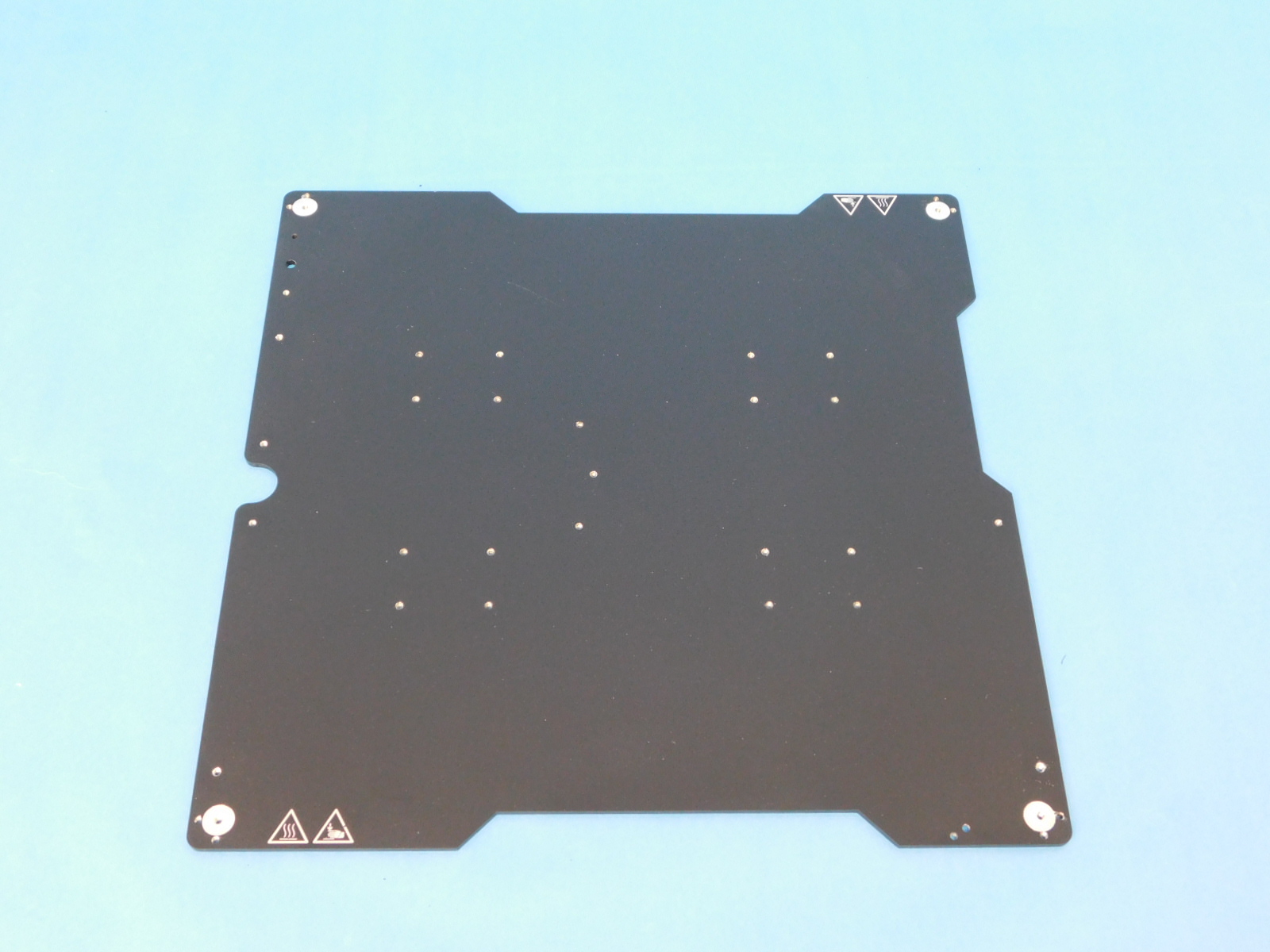
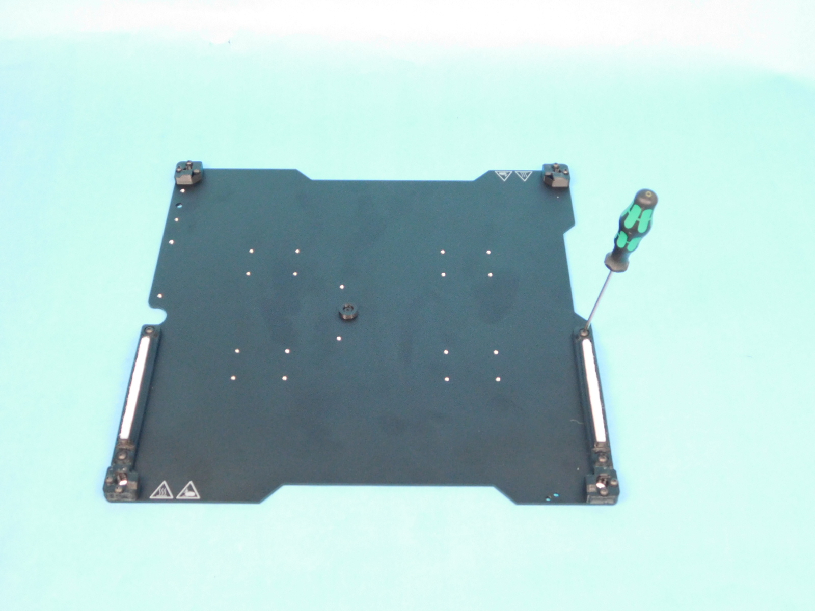
Start with the bed plate [PP-MP0216] etching facing up and the half circle cut out is on the left side.
Place the bed corners into position and loosely screw M3x10mm [HD-BT0148] with M3 washers [HD-WA0038] to hold the bed corners.
Add one Heat Bed Standoff [PP-GP0478] to the center hole on the bed plate using one M3x6 FHCS [HD-BT0128]
Tighten until finger tight
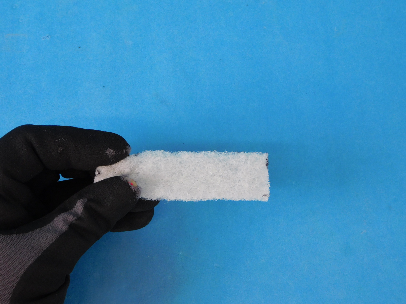
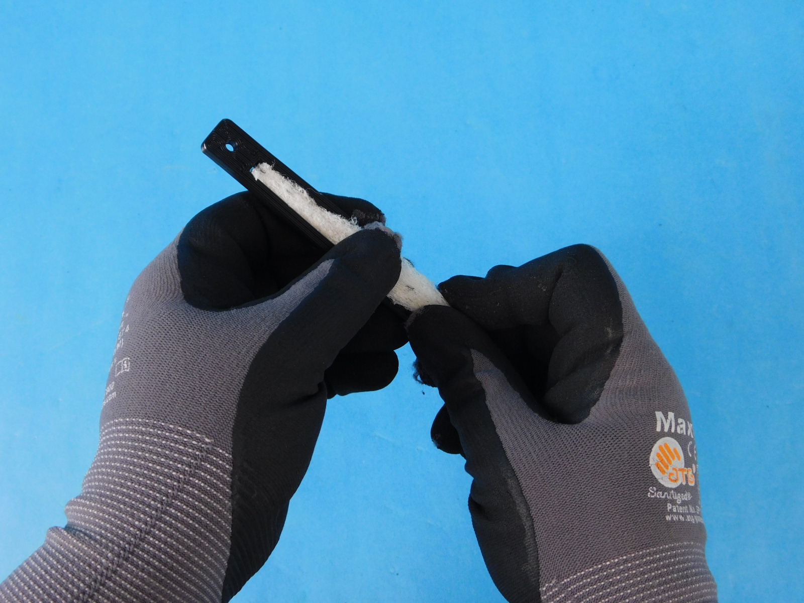
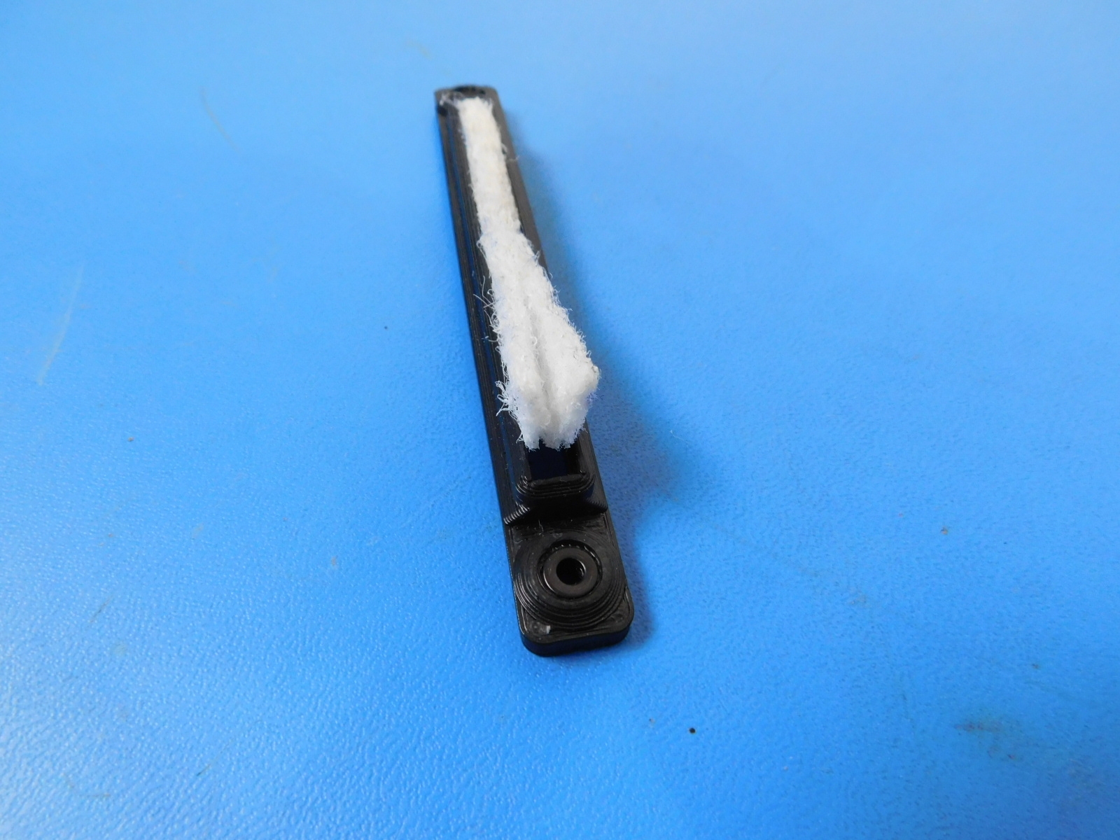
Take a white scotch brite pad [HD-MS0531] and a wiper mount [PP-GP0381]. Fold the white scotch brite pad in half and insert it in to the wiper mount with the 'valley side up'.
Loosely install two wiper mounts [PP-GP0381] to the bed plate using two per: M3x10 BHCS [HD-BT0148] with washers [HD-WA0038]
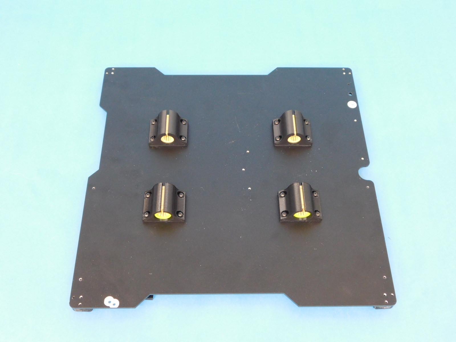
flip the bed plate to the right 180°.
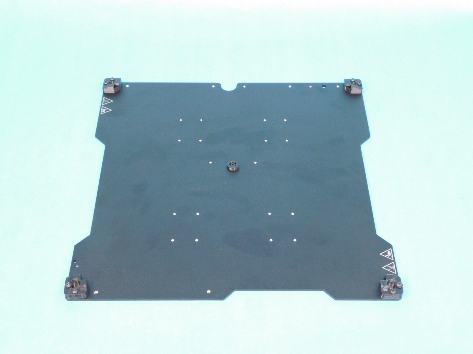
Place the 4x Y bearing holders [PP-GP0393] with the retaining rings facing to the outside of the plate.
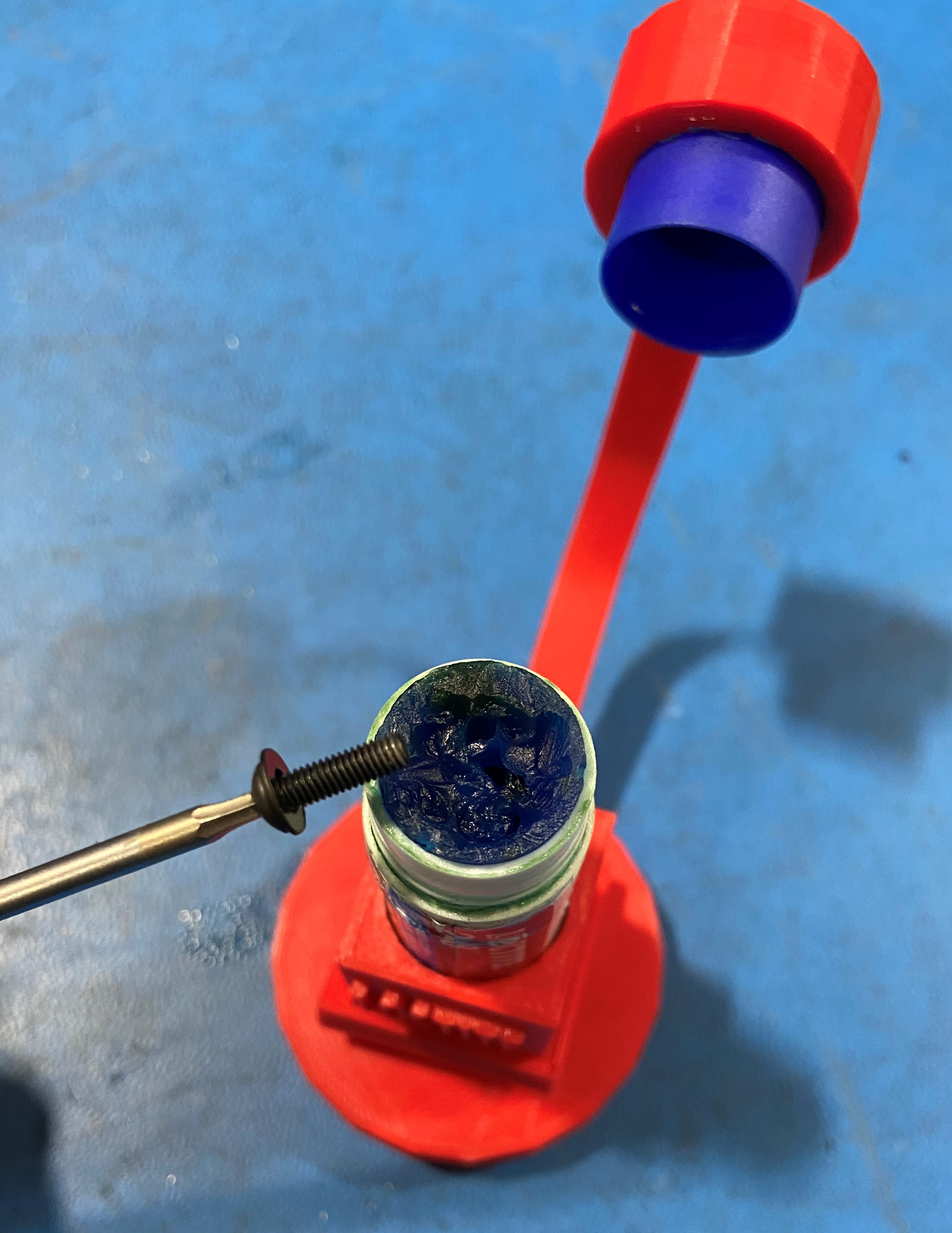
Using Loctite 248 on the M3x10 screws [HD-BT0148] that have M3 washers [HD-WA0038] loosely secure the Y bearing holders.
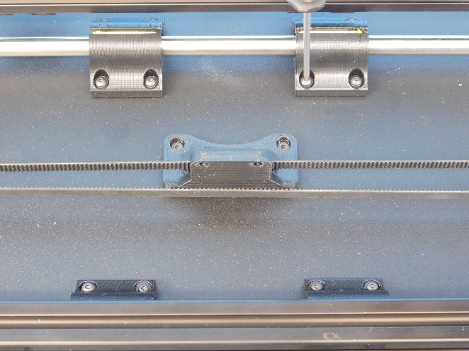
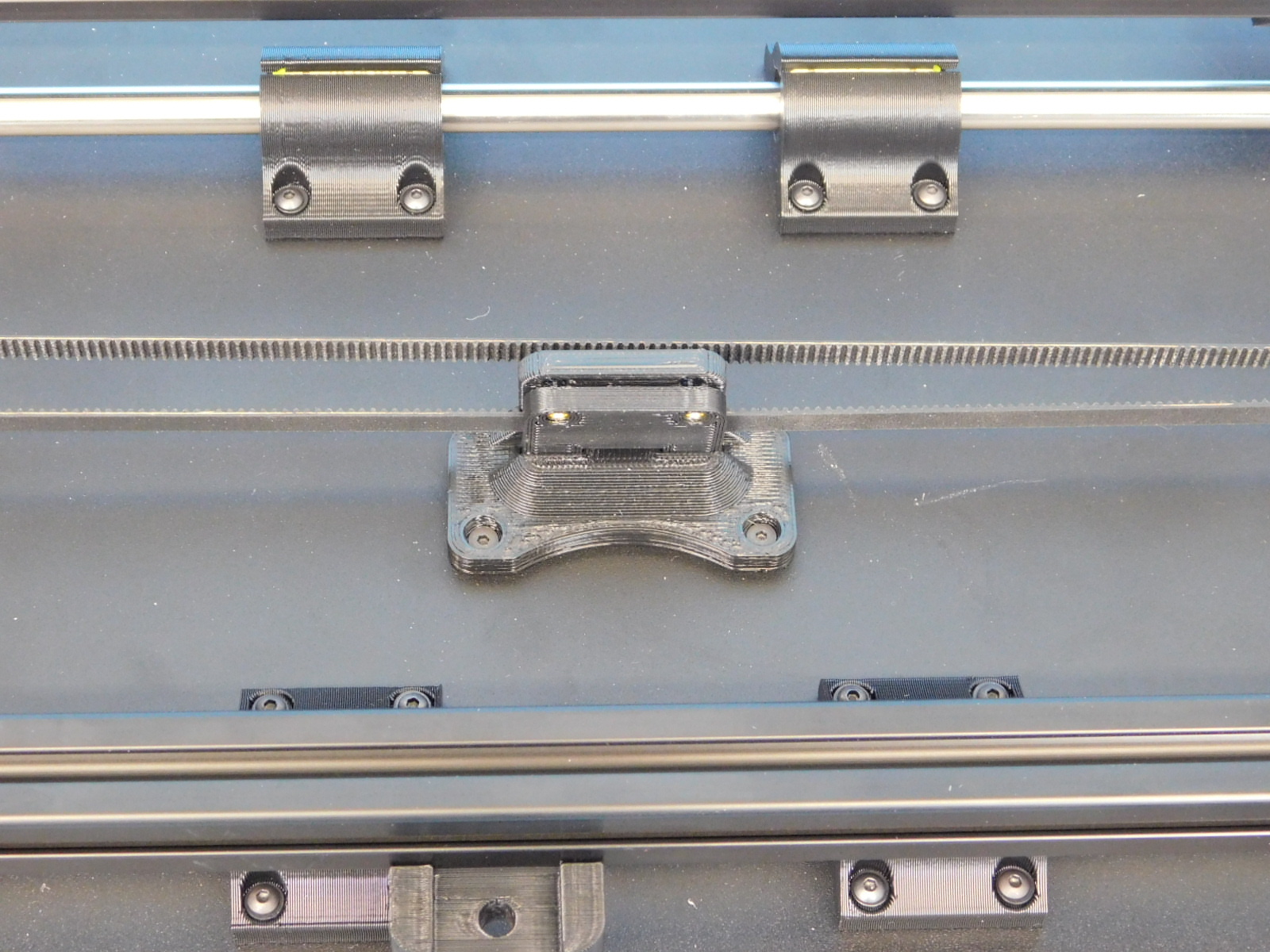
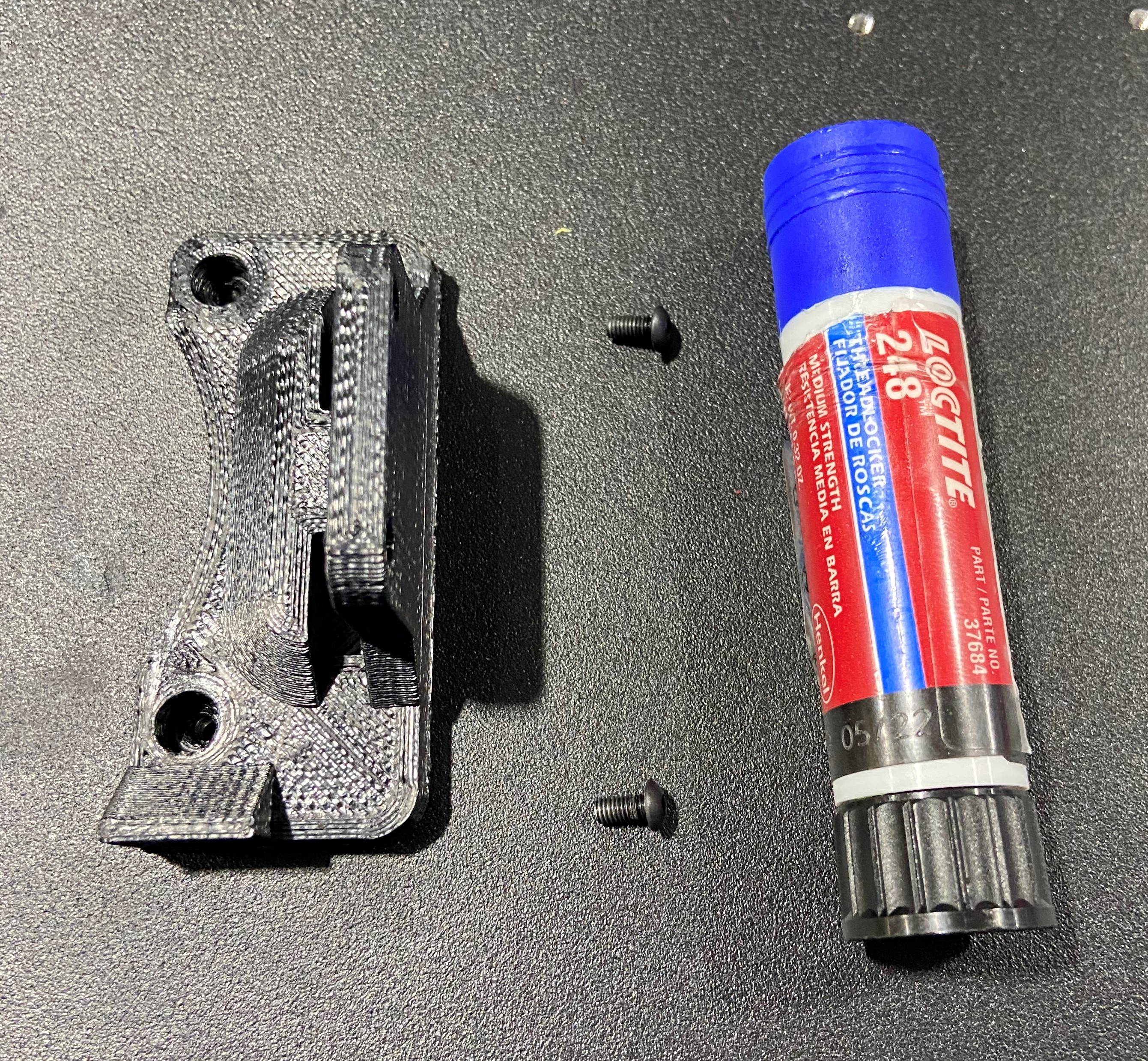
Using Loctite 248 on the fasteners, install one Y belt mount [PP-GP0369] to the bed plate using 2x- M3x6 BHCS [HD-BT0140]. torque to 5in*lbs
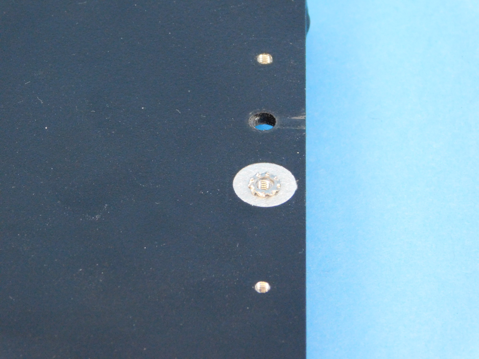
Next, in the upper right corner, place the External Serrated Lock Washer [HD-WA0035] over the masked threaded screw hole.
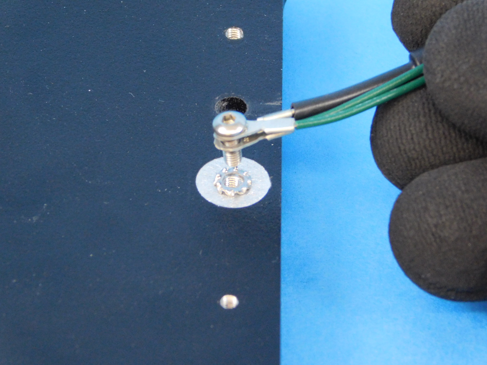
Obtain one Bed Extension Harness [EL-HR0146]
Put a M3 x 8 SST screw [HD-BT0104] through the three terminal rings, in no specific order, and secure the harness to the bed.
Torque to 5in*lbs
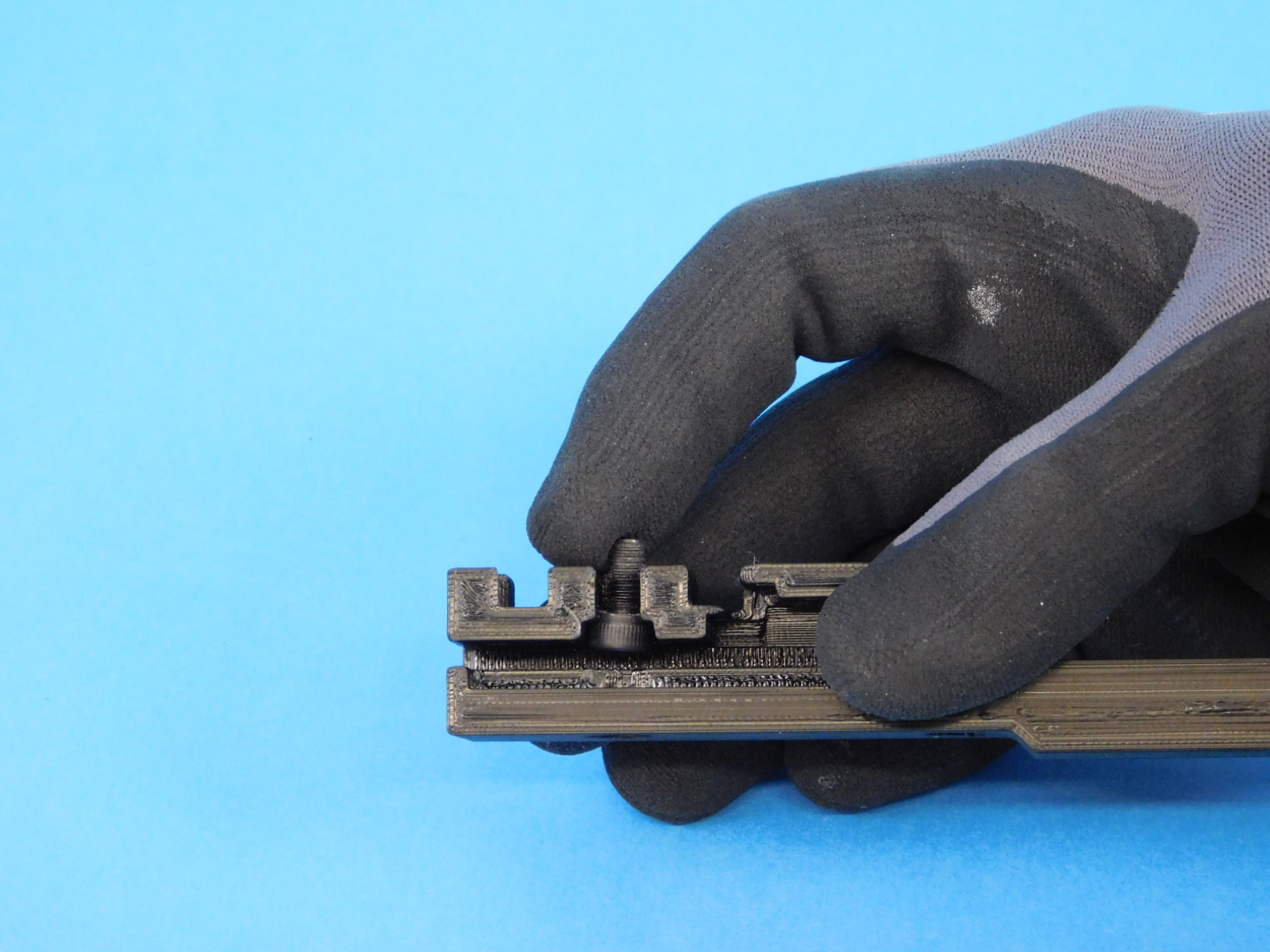
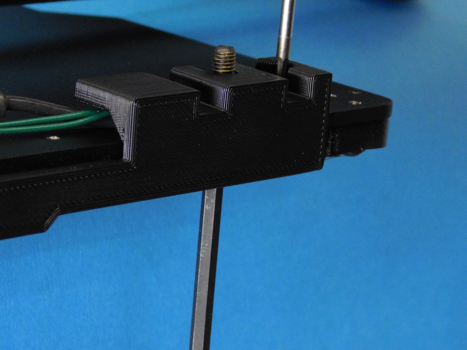
Hold the Y cable cover [PP-GP0391] in position with the M5x10 screw.
Slide the Y cable cover onto the bed plate while holding the M5x10mm [HD-BT0048]in place.
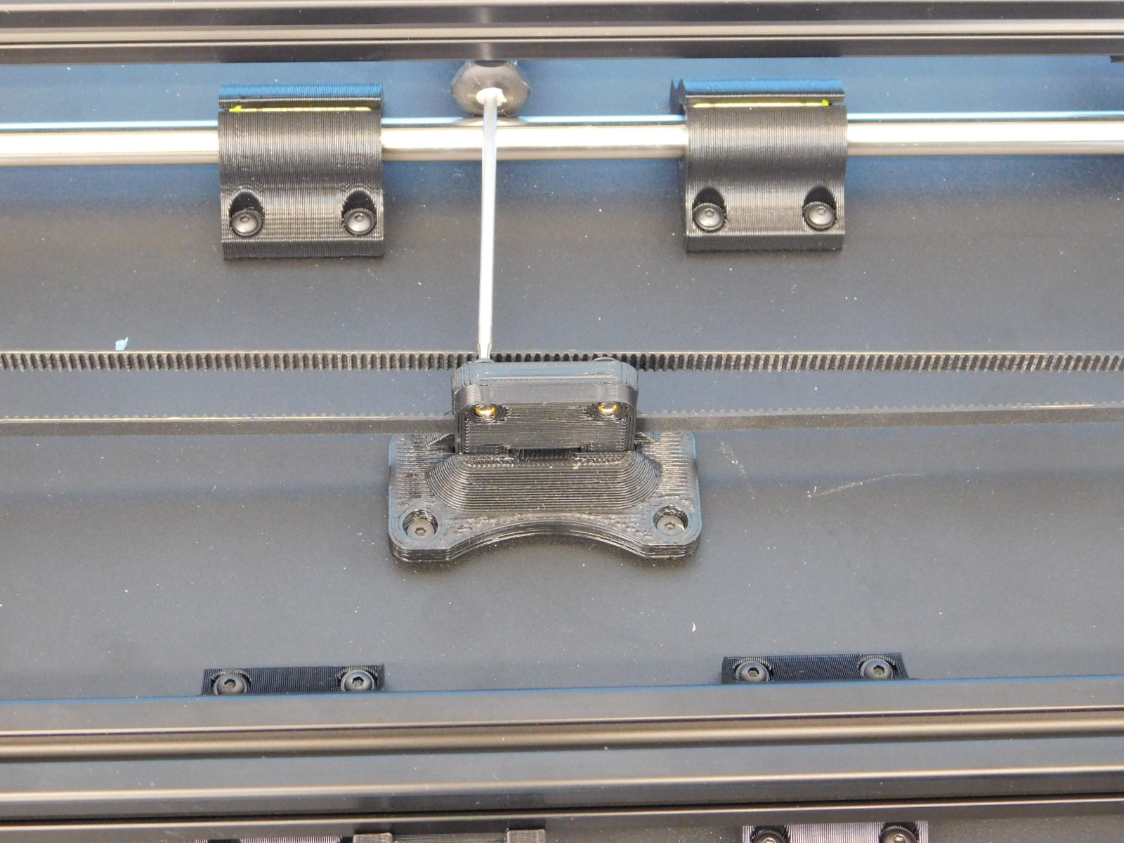
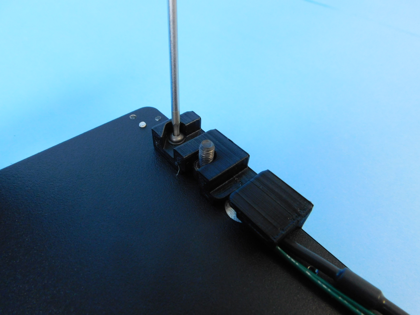
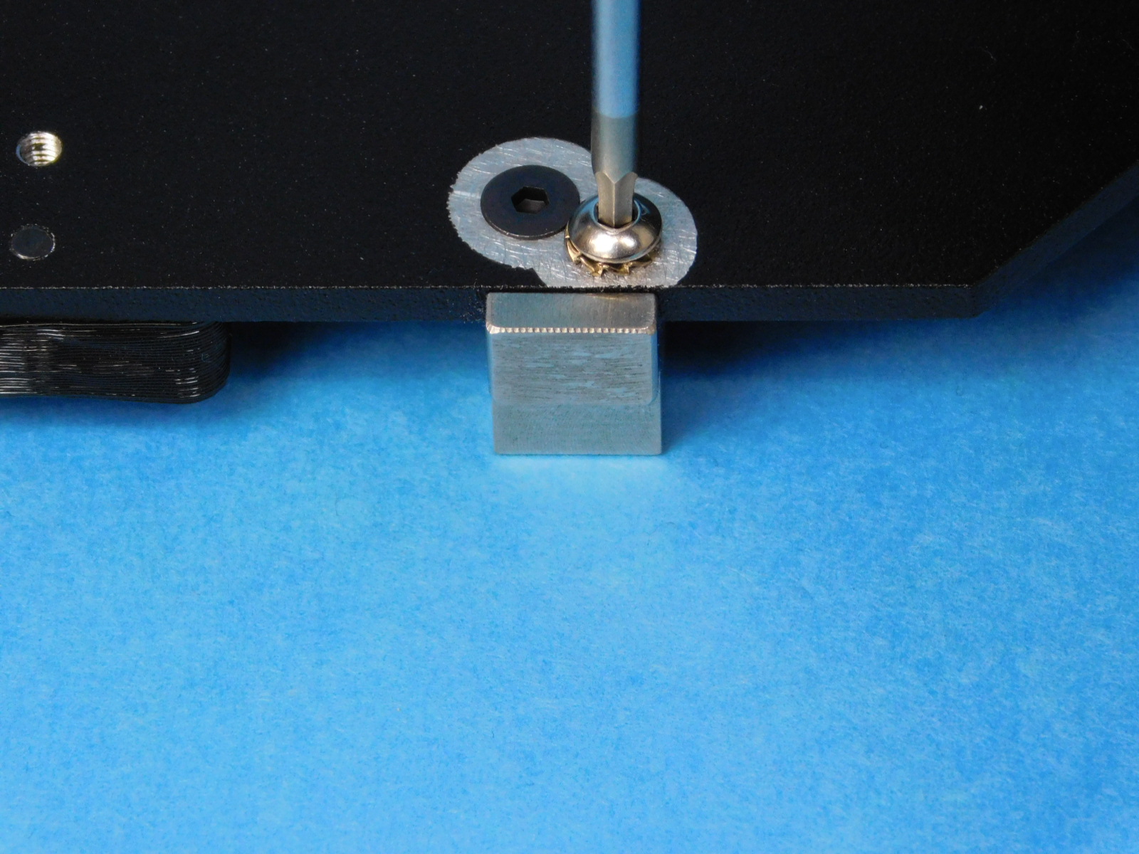
Place a 4mm hex driver through the hole in the bed plate/Y Cable cover from the other side, ensuring the driver has proper engagement with the fastener head. This ensures proper alignment of the fastener head to the hole in the bed plate; keep the driver straight vertically.
Secure with a M3x10 [HD-BT0148]
torque to 5in*lbs
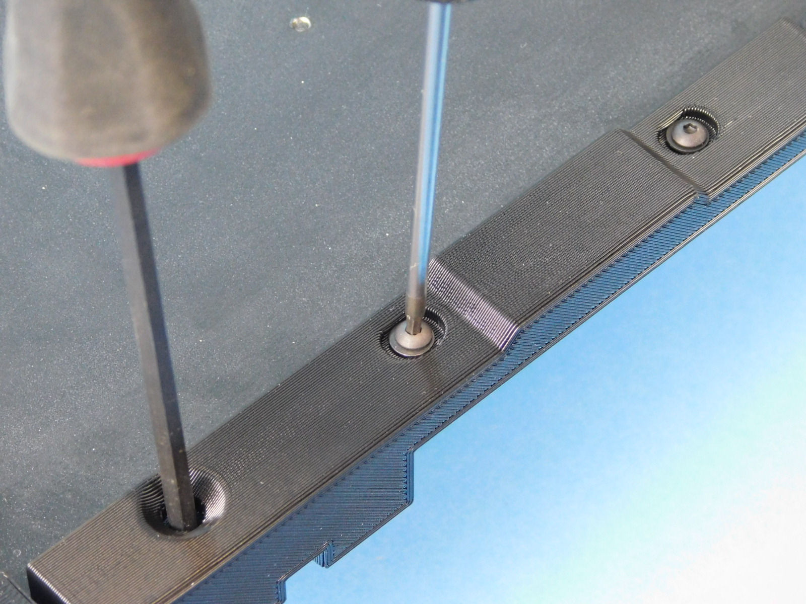
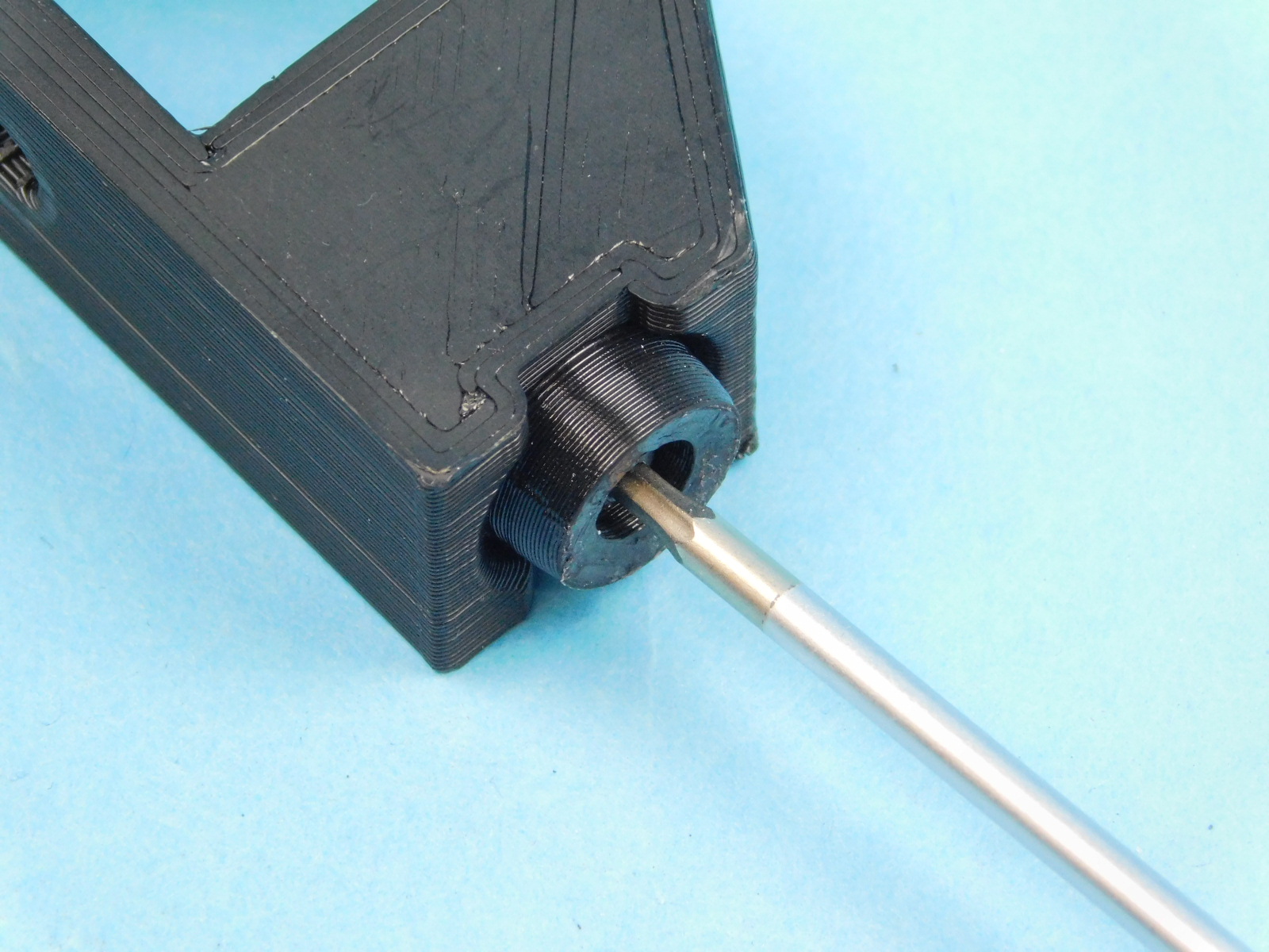
Flip the assembly over and insert the 4mm hex driver; again ensuring that the fastener head remains aligned with the hole in the bed plate.
Secure the Y Cable Cover on top using two more M3x10 BHCS [HD-BT0148]
Torque to 5in*lbs
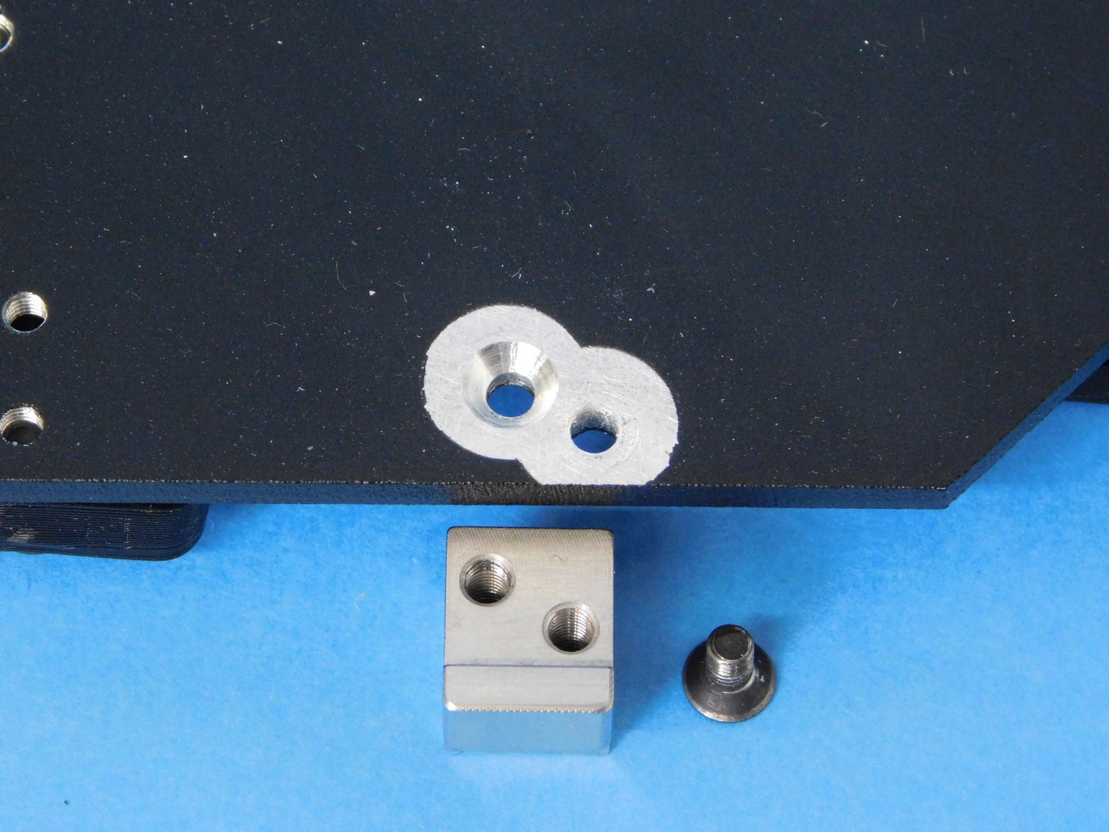
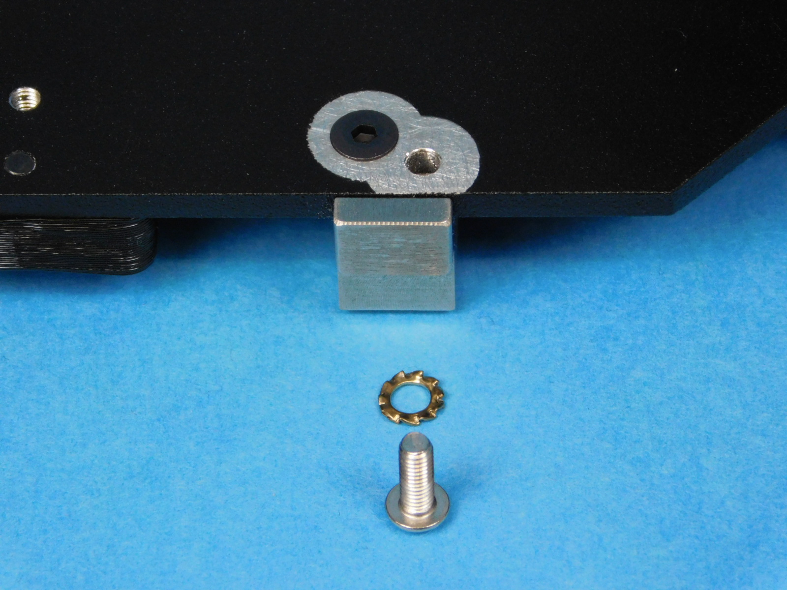
Next, fasten the XY Calibration Cube [PP-MP0227] with a M3x6 Flat head screw [HD-BT0128] and secure with a M3 x 8 SST screw [HD-BT0104] and External Tooth Lock Washer [HD-WA0035].
Torque both fasteners to 5in*lbs
Set aside for the next half of the Y-bed assembly.


1x- [AS-PR0122] Y end Idler End
1x- [AS-PR0123] Y end Motor Mount End
1x- [AS-PR0124] Y Idler Assembly
1x- [EL-MT0029] NEMA 17 Stepper Motor
17x- [HD-BT0073] M5x10 BHCS
10x- [HD-BT0148] M3x10 BHCS
2x- [HD-EX0062] T-Slot Extrusion 20x20x500mm
1x- [HD-MS0033] 16 Teeth, timing pulley
1x- [HD-MS0411] Premium Two Side Rubber Sealed Bearing
8x- [HD-NT0053] T-Slot Slide in T-nuts for Aluminum Frame, M5
2x- [HD-RD0018] 10mm Smooth Rod, Stainless Steel, 500mm
10x- [HD-WA0038] M3 Washer Black Oxide
17x- [HD-WA0040] M5 Washer Black Oxide
4x- [PP-GP0238] Flexy Bed Foot v0.1
2x- [PP-GP0364] Y corner right
2x- [PP-GP0365] Y corner left
4x- [PP-GP0368] Y bump stop
1x- [PP-GP0370] Y belt clamp
4x- [PP-GP0395] Bed mount table
Attach one flexy bed foot [PP-GP0238] to each Y-Corner [2x- PP-GP0365 & PP-GP0364] using one M3x10 BHCS [HD-BT0148] with washer [HD-WA0038]
Tighten the fastener until it begins to compress the flexy bed foot and the foot can no longer rotates easily.
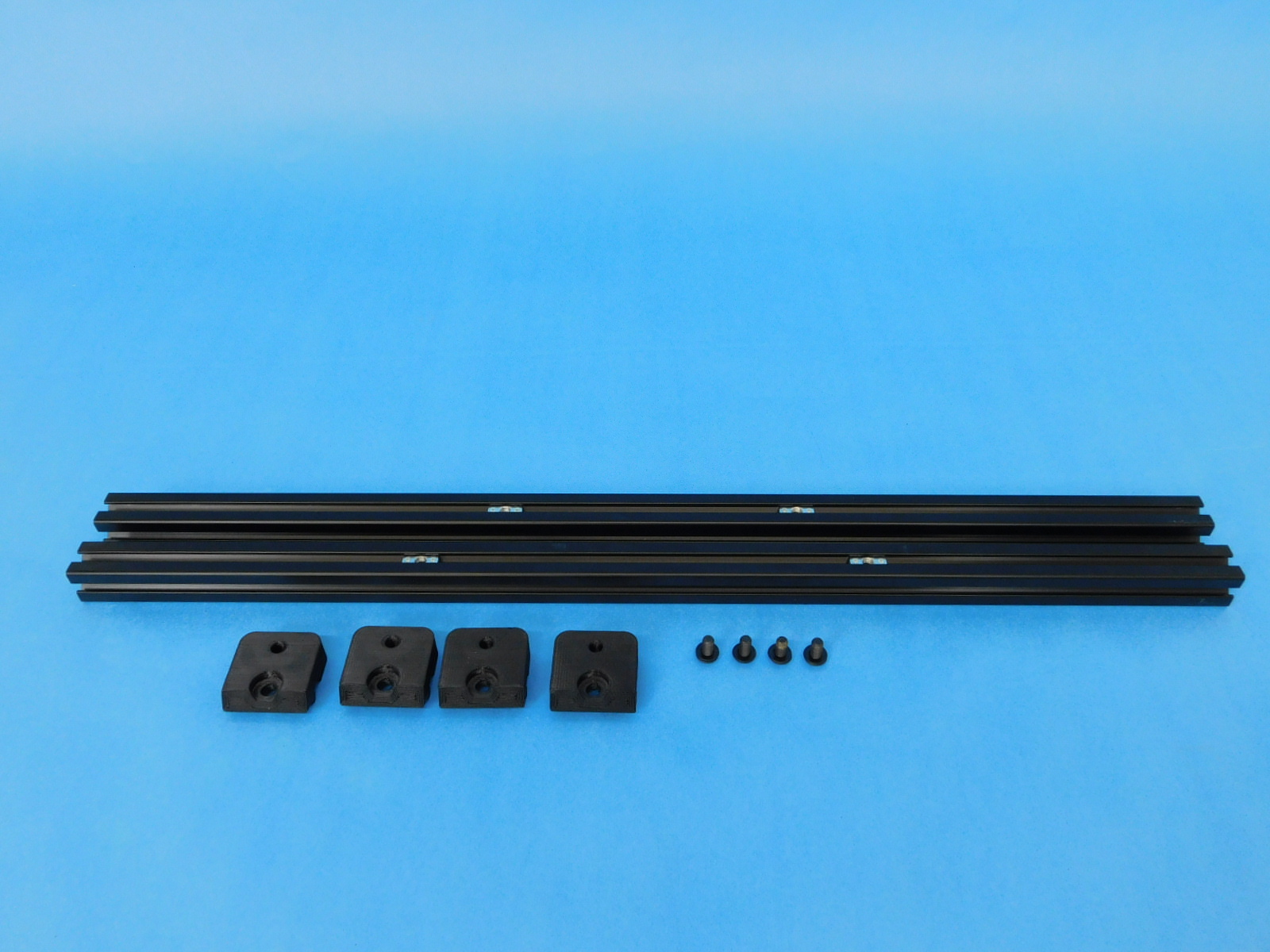
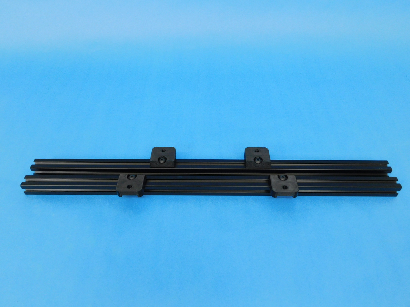
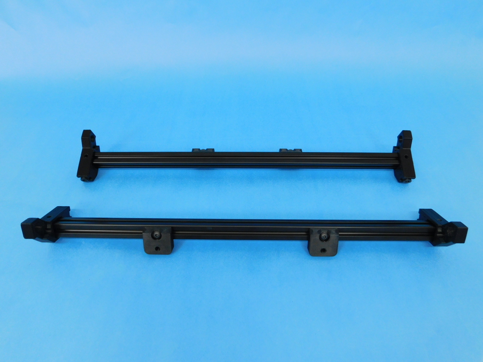
Place two extrusion [HD-EX0062] horizontally with two T-nuts [HD-NT0053] in each extrusion.
Place the Y bed mount table [PP-GP0395], as shown, with the first layer print surface angle facing each other.
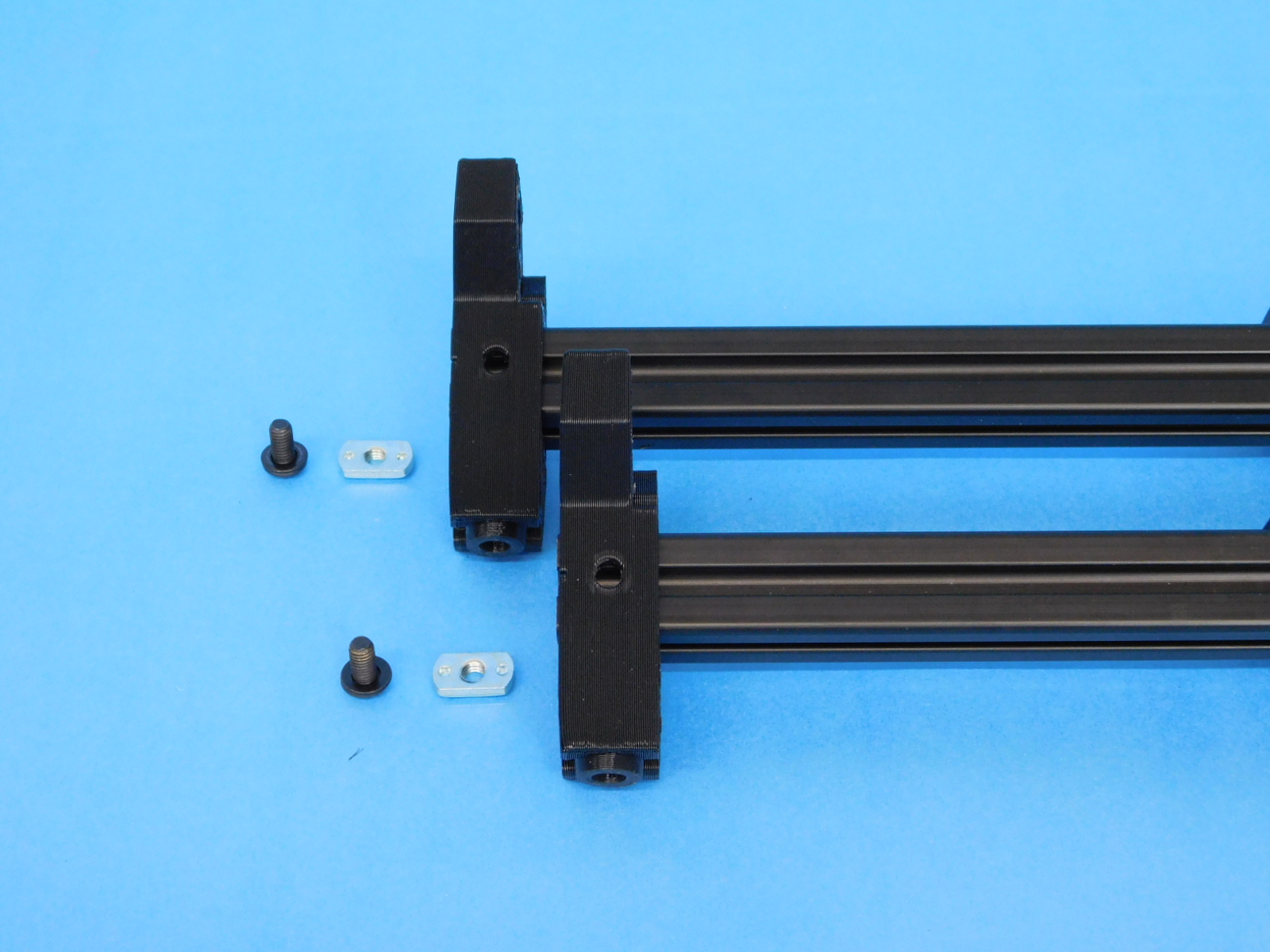
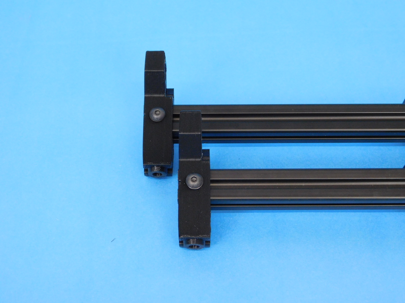
Secure the bed mount table with a [HD-WA0040] M5 washer and [HD-BT0073] M5x10 screw. These fasteners do not need torque applied yet; they will be adjusted during Final Assembly.
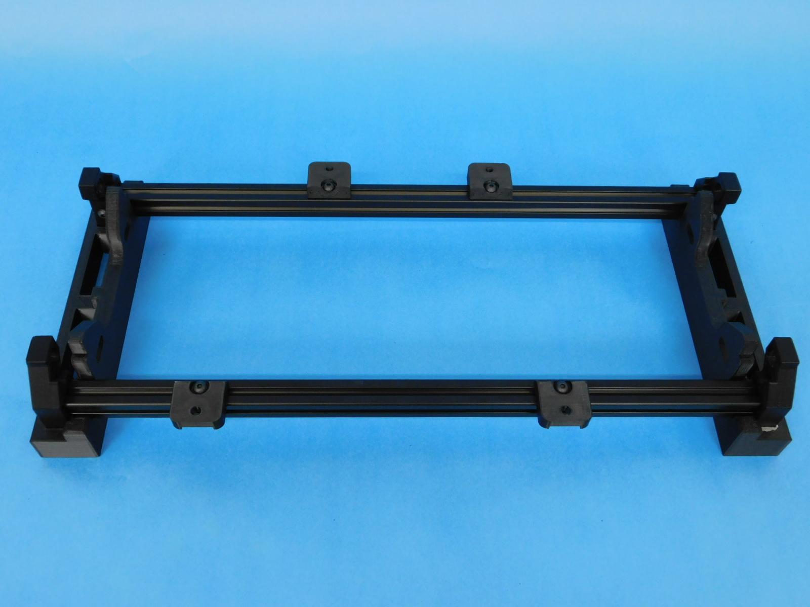
Insert one Y corner right [PP-IS0090] & one Y corner left [PP-IS0089] on each extrusion, as shown in the example photo.
Secure the Y-corners using T-nuts [HD-NT0053], M5 washer [HD-WA0040], and M5x10 screw [HD-BT0073]. Repeat for both sides and torque these fasteners to 5in*lbs

Wipe down the smooth rods to ensure they are free from any contaminants.
Using the Y-axis jig. Set the Y-corners into the jig with the corners curved inward. Using a 10mm Smooth Rod [HD-RD0018] and Y bump stop [PP-GP0368].
Halfway insert the rod while holding the bump stop on the inside of the Y-corner. Repeat for the otherside.
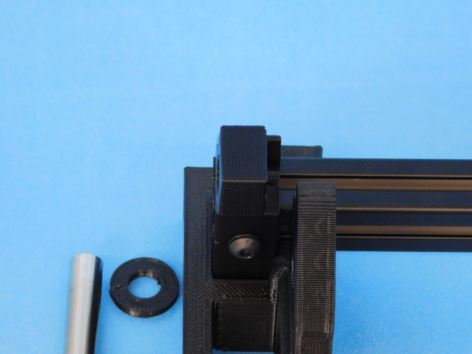
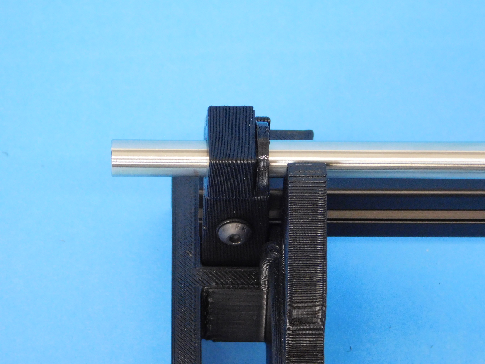
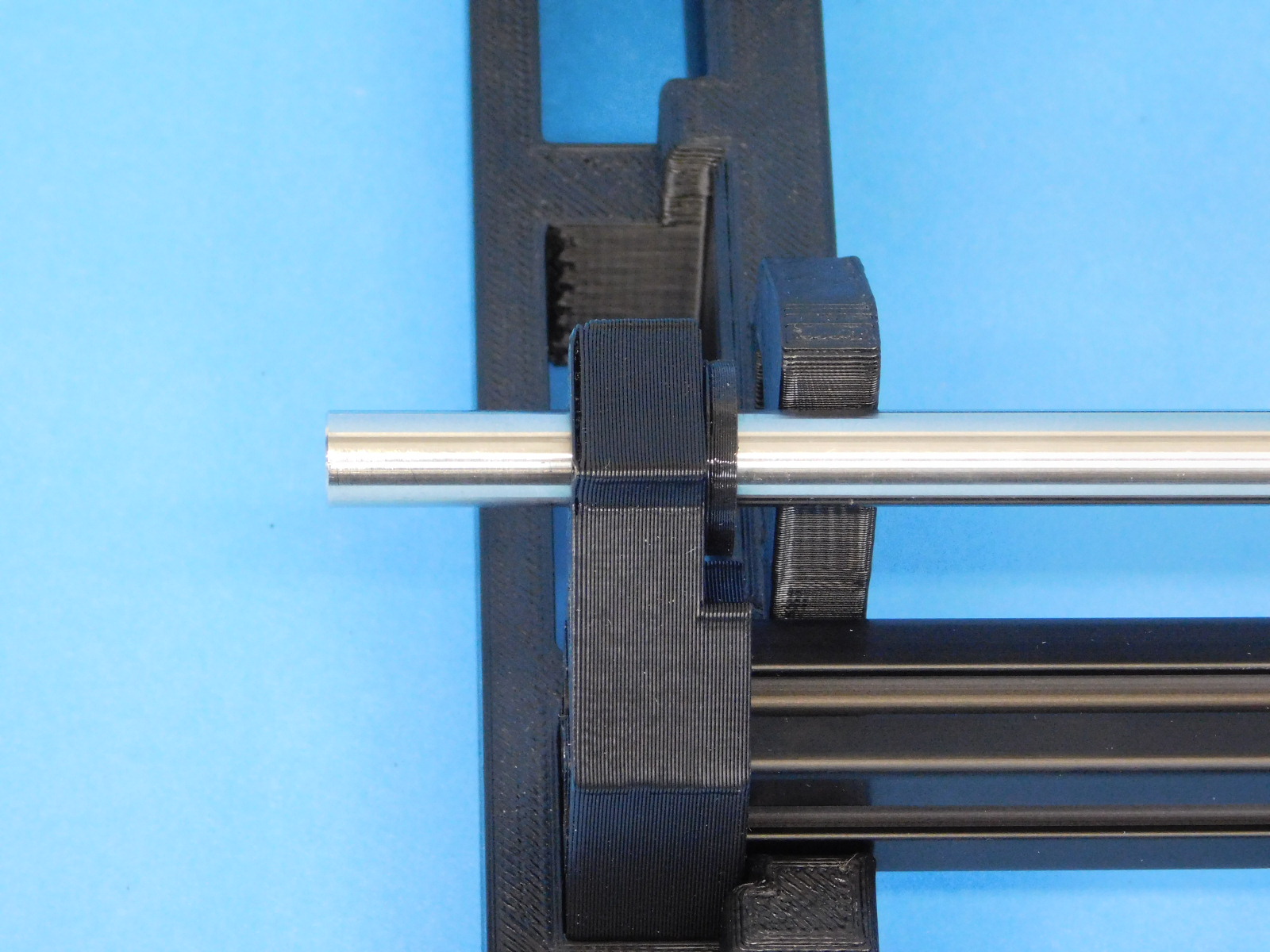
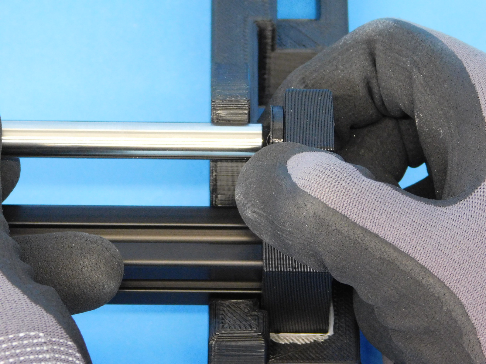
Take the Y-bed and assemble the smooth rods through the Y-bearing holders. Continue to push/pull the rod through till you get close to the Y-corner.
Grab another Y bump stop [PP-GP0368] and hold said part till you have fully inserted the smooth rod flush with the Y-corner. Repeat For the other side.
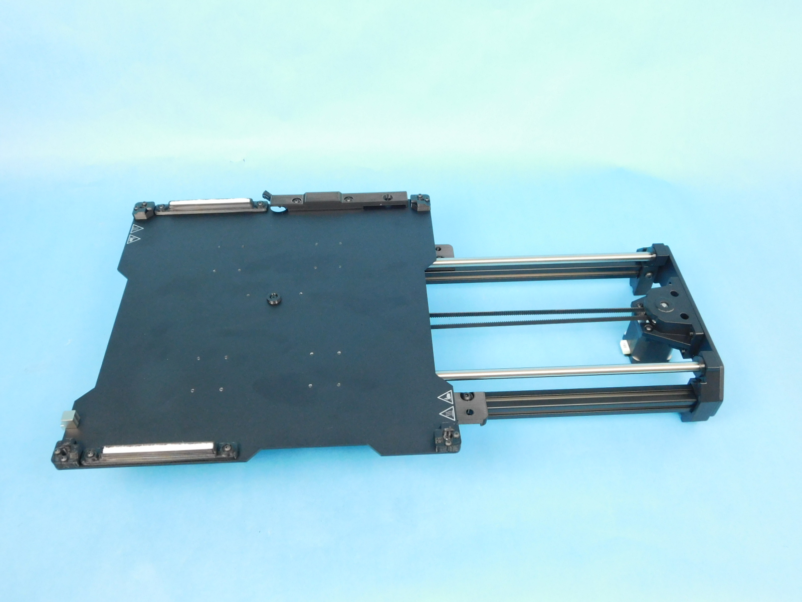
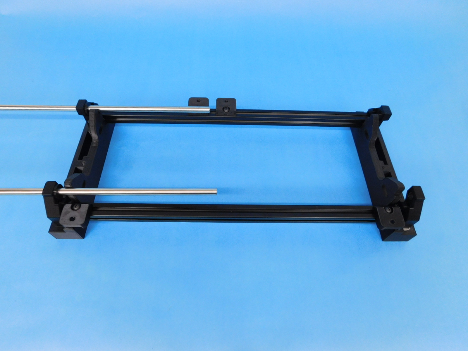
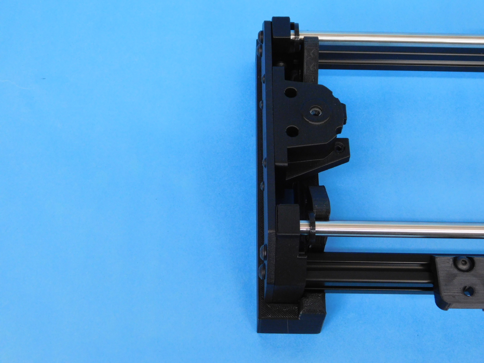
Assemble the side further from the wiper mounts with a Y-motor end using 4x [HD-WA0040] & 4x [HD-BT0073] M5x10. Torque fasteners to 5in*lbs
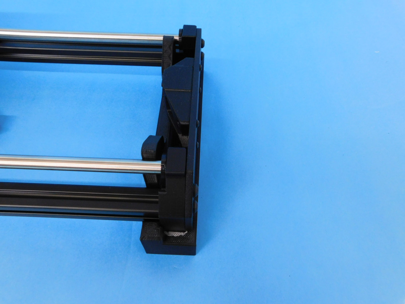
Assemble the side closest to the wiper mounts with a Y-idler end using 4x [HD-WA0040] & 4x [HD-BT0073] M5x10.
torque to 5in*lbs


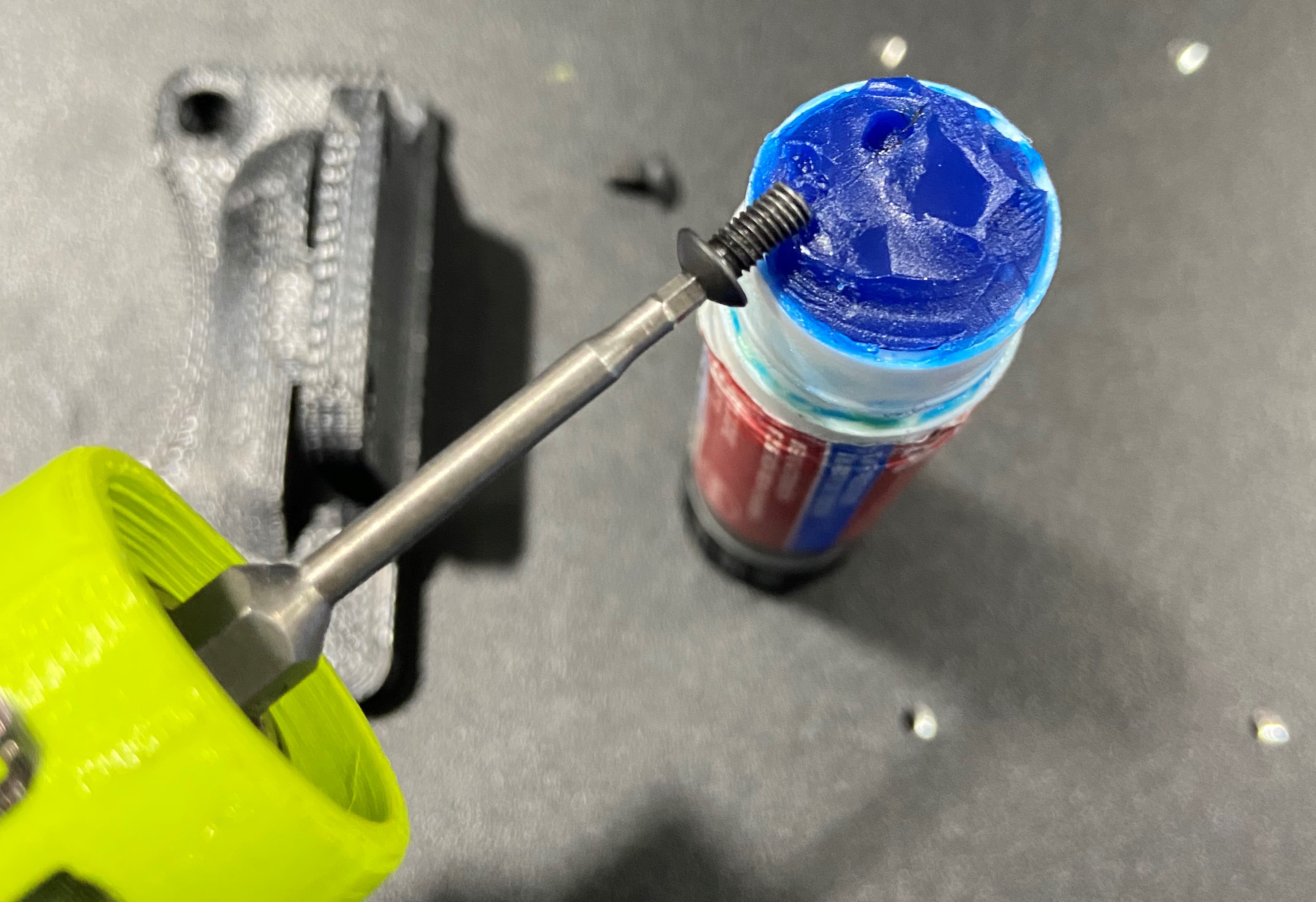
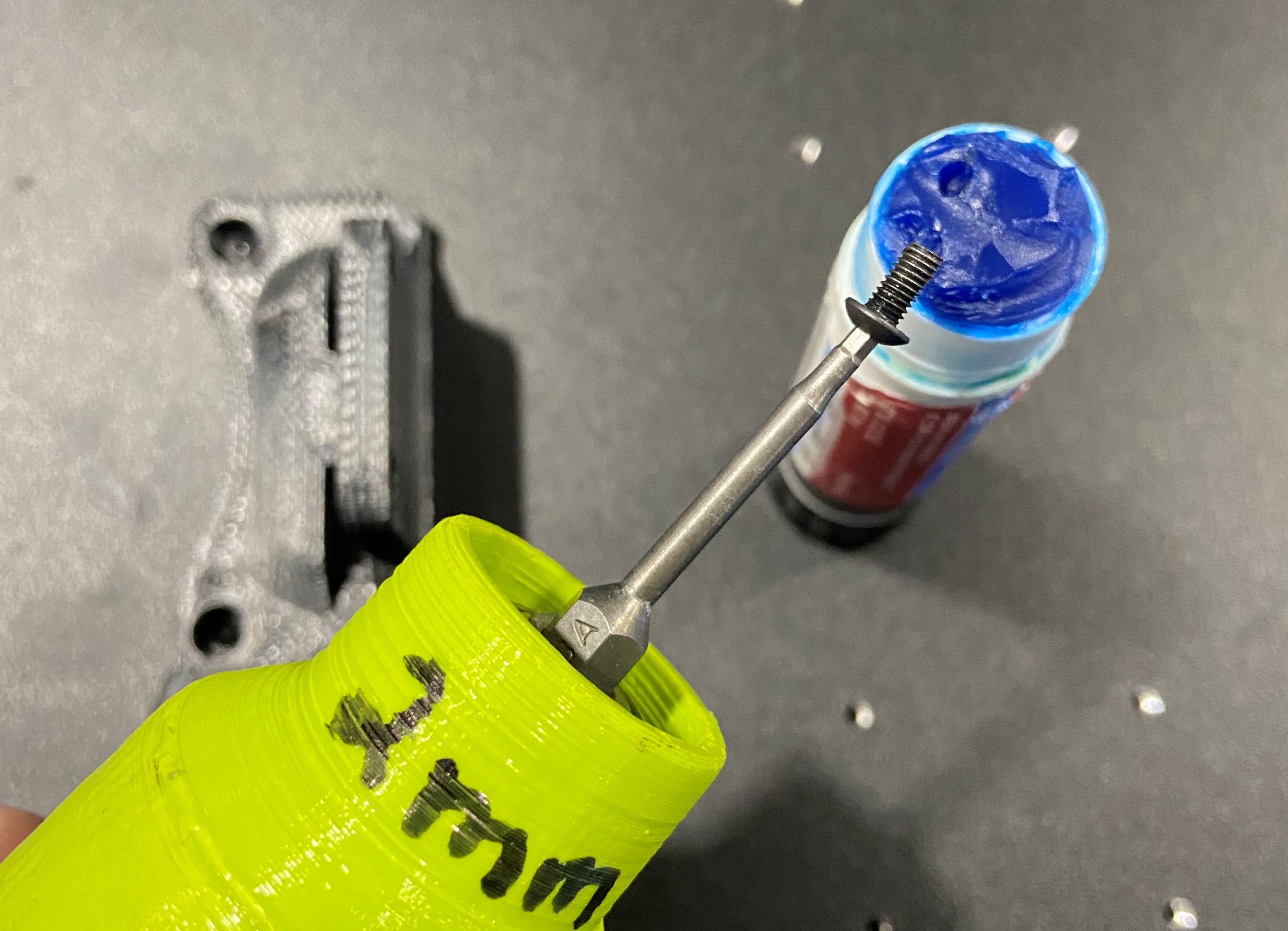
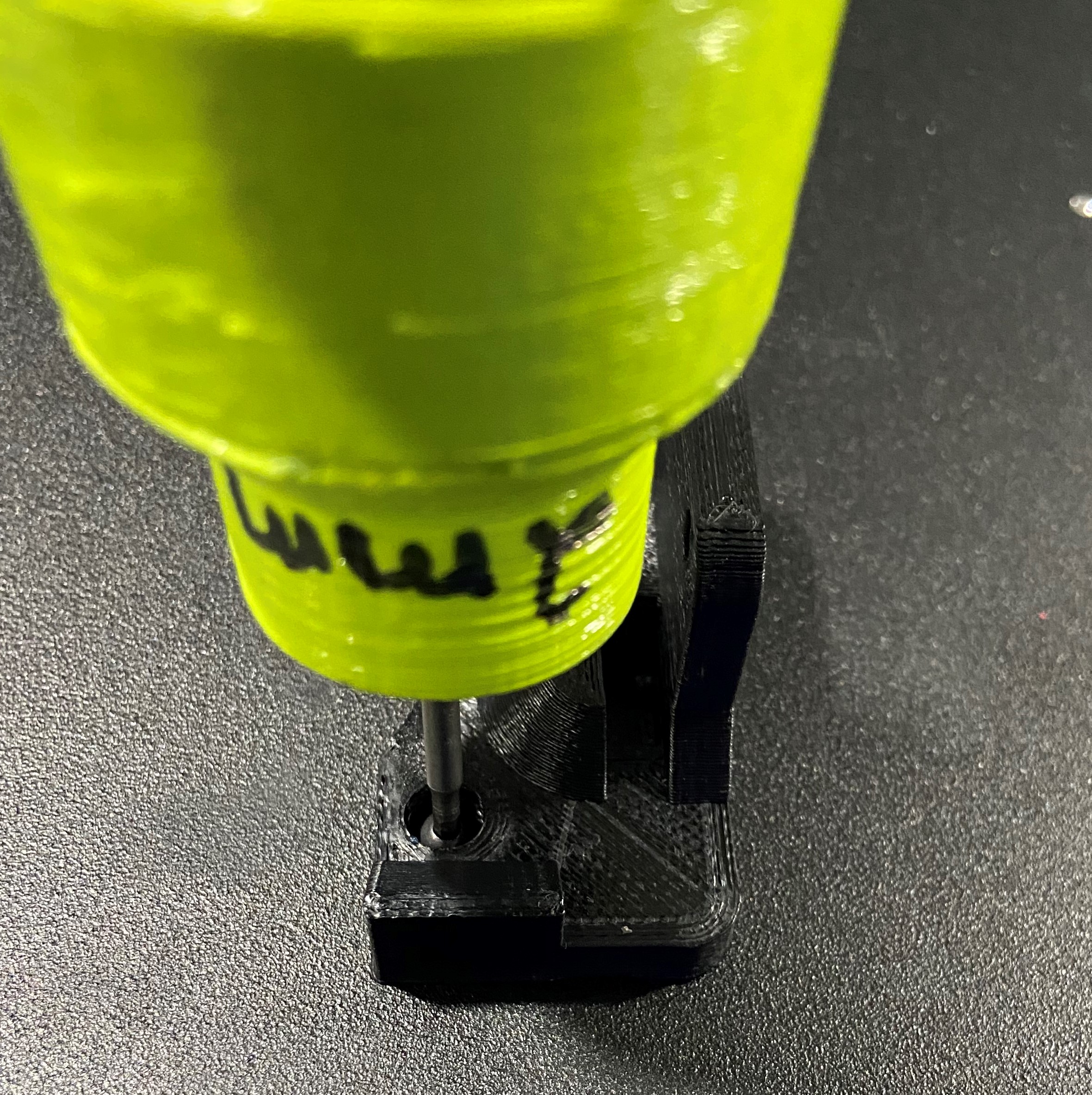
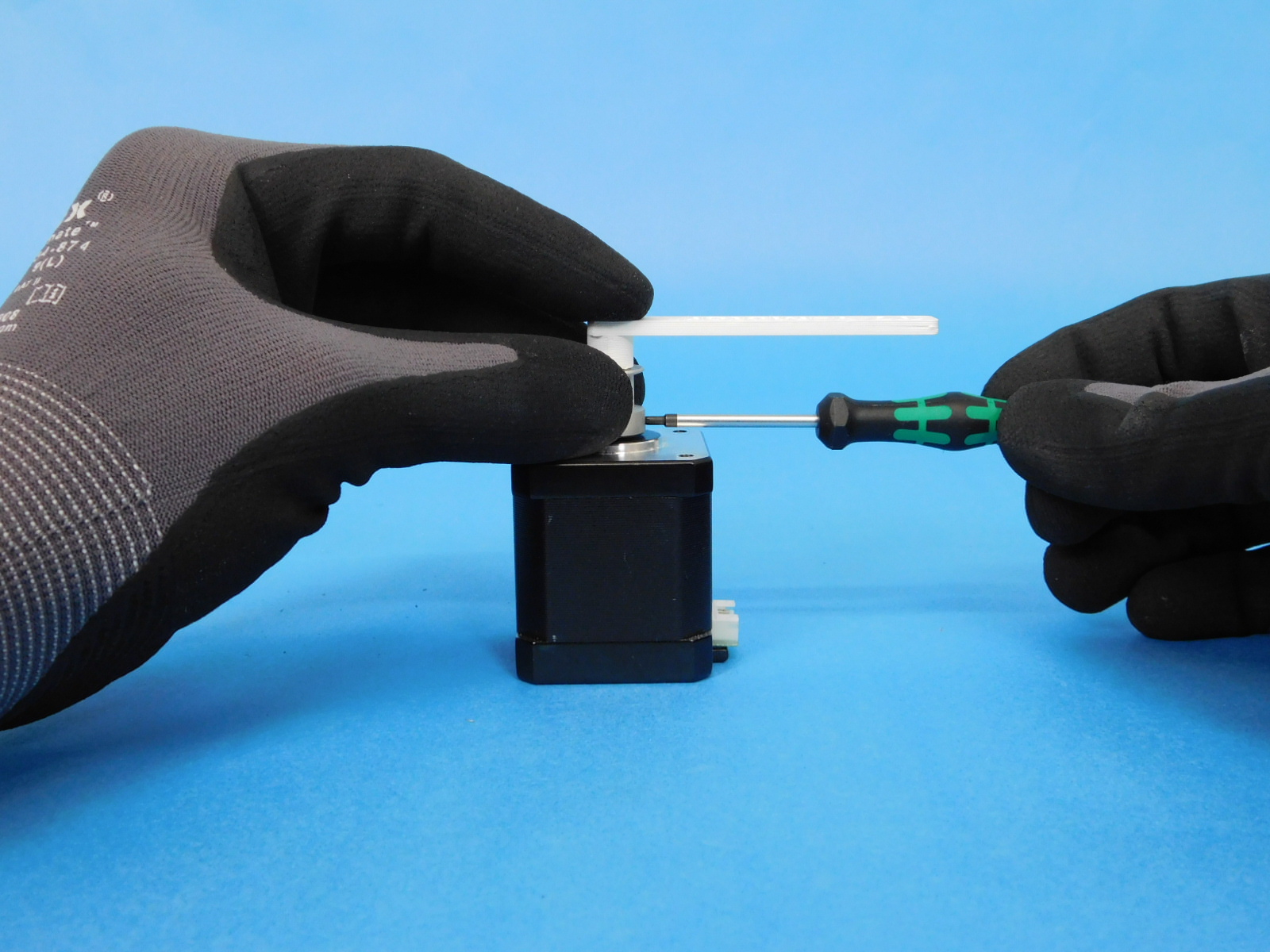
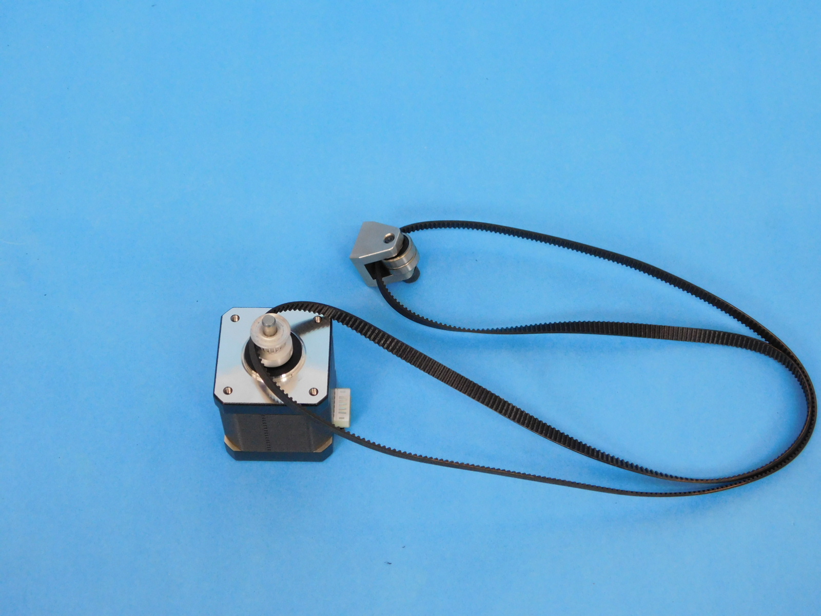
Set the pulley GT2, 16 Teeth, timing pulley, AL [HD-MS0033] onto the NEMA 17 Stepper Motor [EL-MT0029]. Measure with a Y-motor height jig to tighten the set screws to ensure the pulley is at the correct height. Ensure that the first set screw is tightened on the flat portion of the motor shaft.
torque both set screws to 3in*lbs
Straighten the Y-Idler Belt [AS-PR0124] into a loop with no twists, with the machined idler in your right hand, ensure the M5 screw protruding from the machined idler is facing downward. Loop the end in your left hand around the motor pulley.
See example photo.
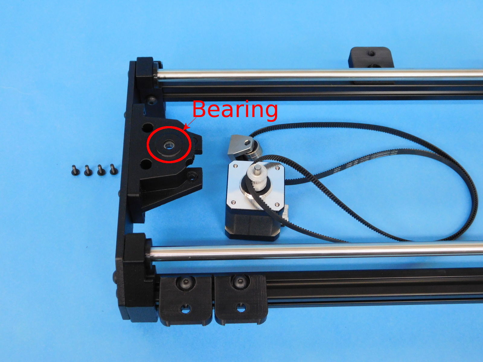
Place one 625-2RS Bearing [HD-MS0411] into the Y-Motor Mount
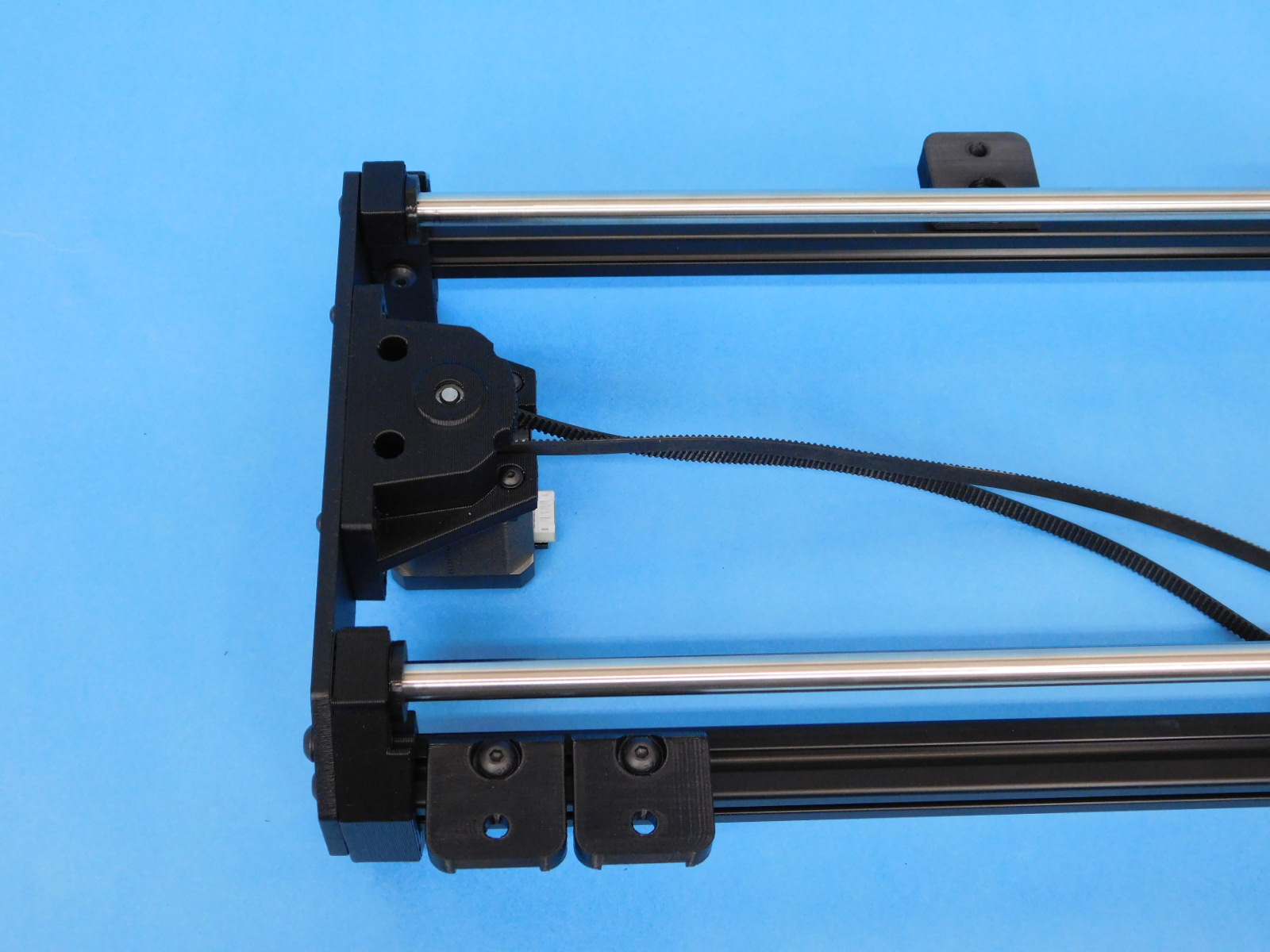
Place the motor shaft into the bearing then use four M3x10 [HD-BT0148] with washers [HD-WA0038] to secure the motor to the Y-motor mount. Torque fasteners to 5in*lbs
Slide the Y-idler assembly into the Y-idler mount slot and tighten with 1x M5 washers [HD-WA0040] & 1x M5x10 BHCS [HD-BT0073]. torque to 5in\lbs
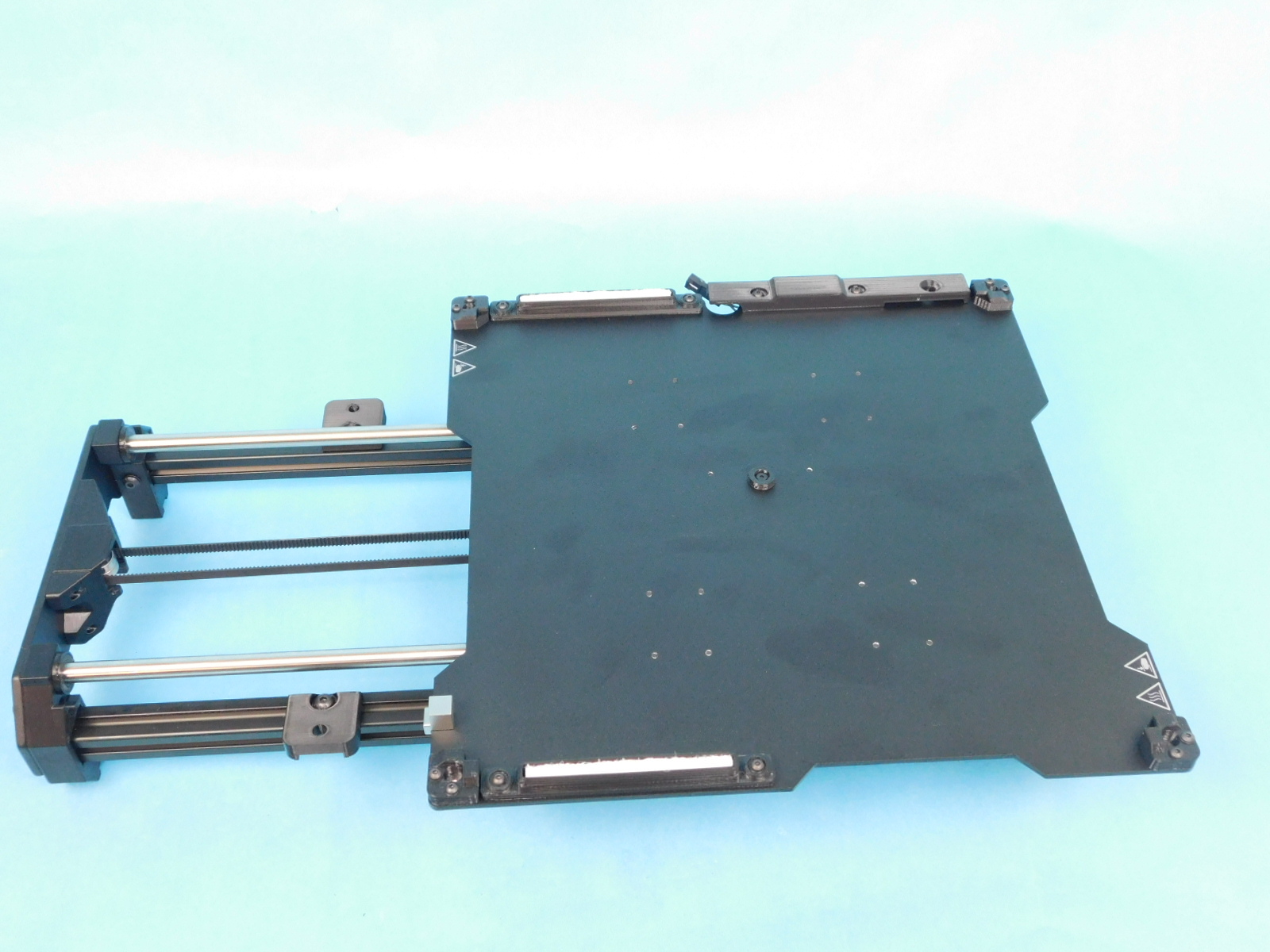
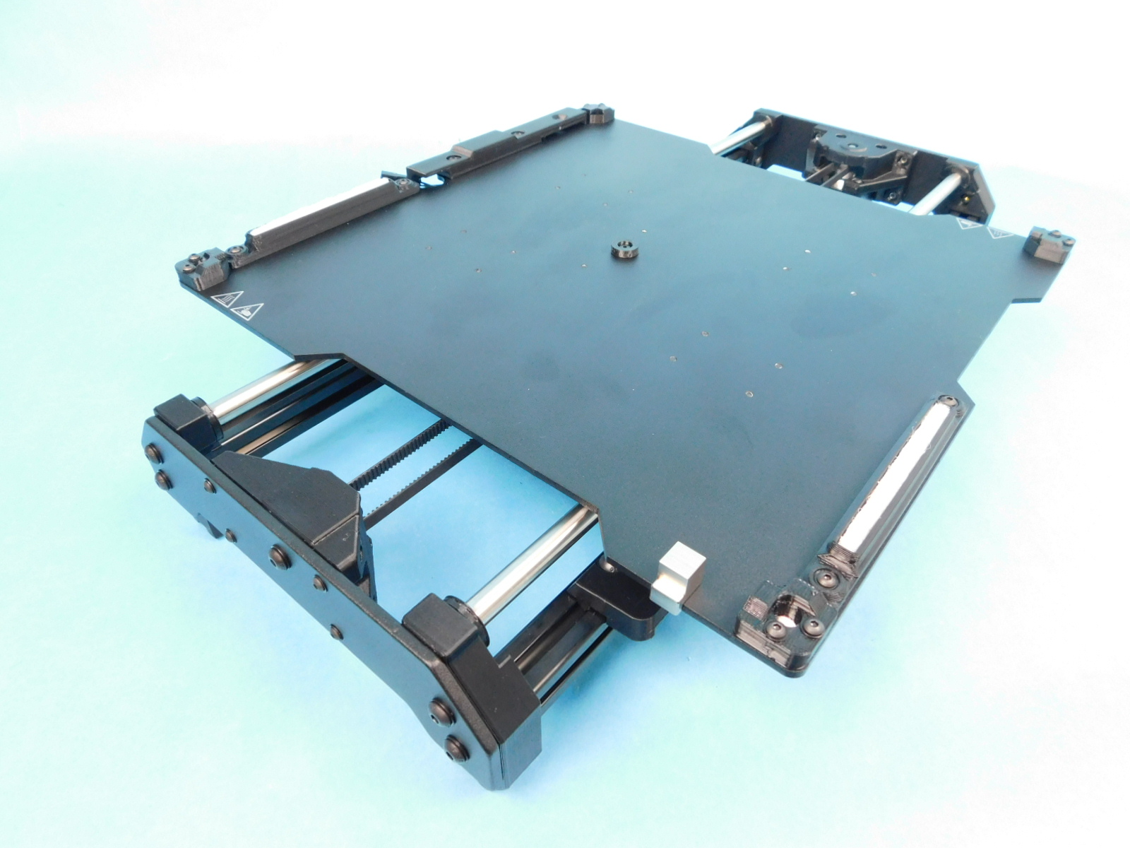
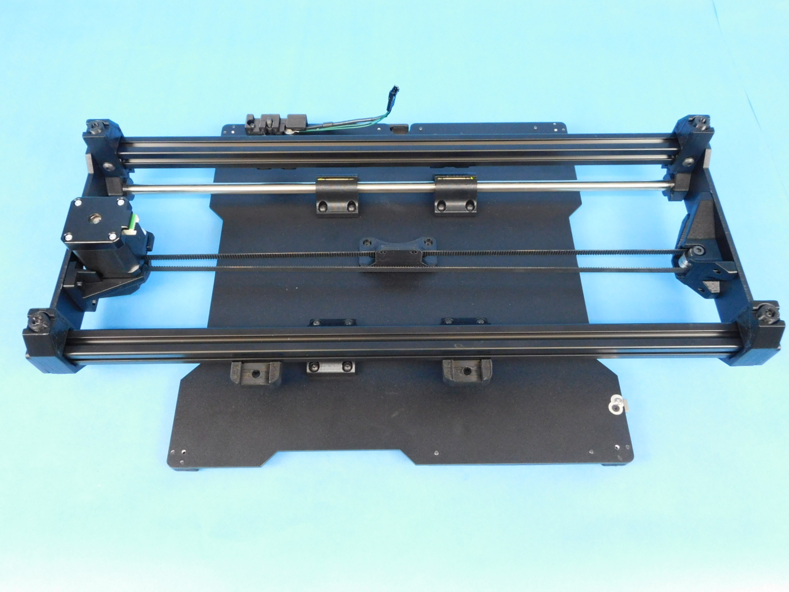
Flip the assembly to access Y-bearing holders.

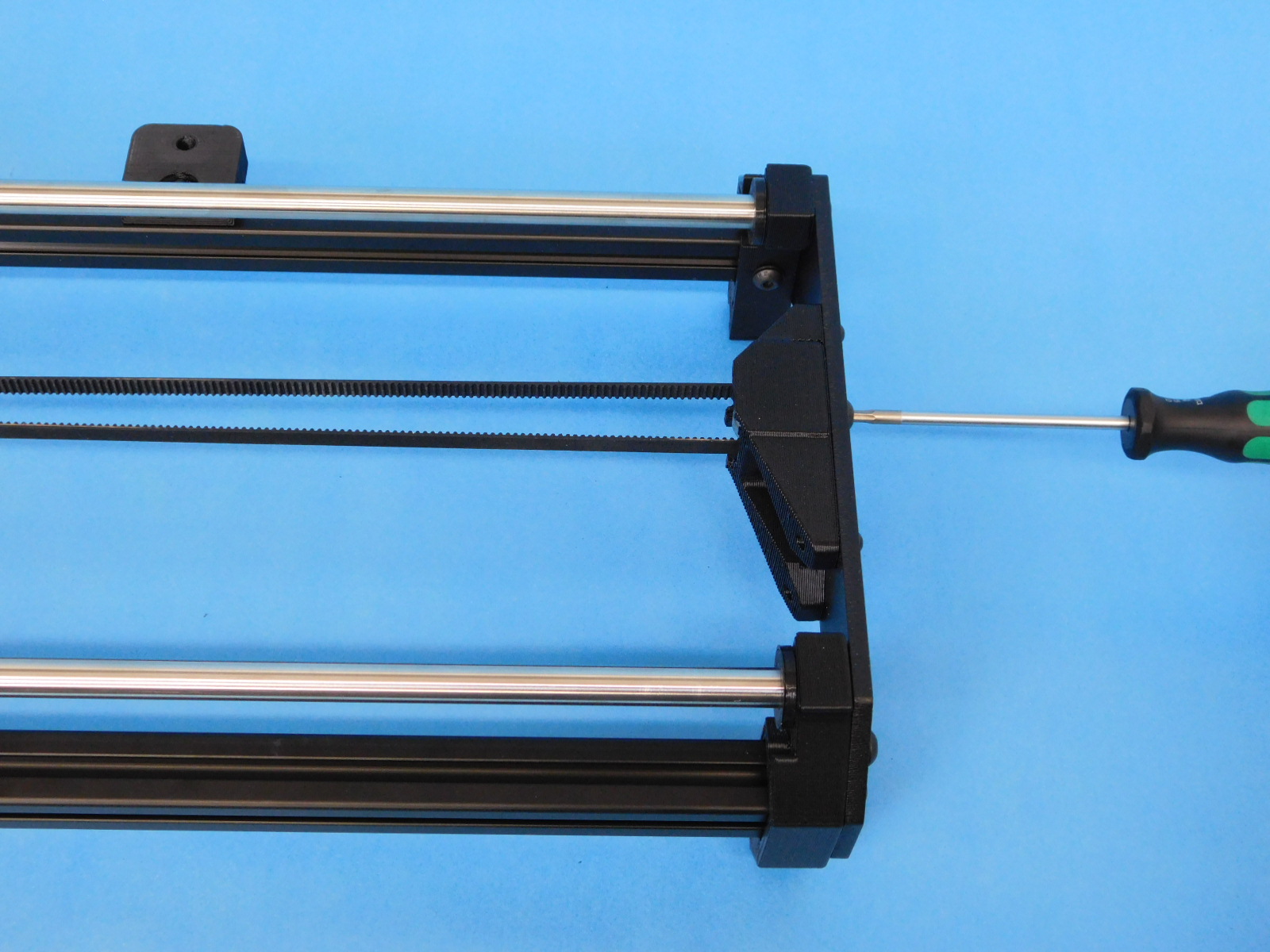
Flip the assembly over
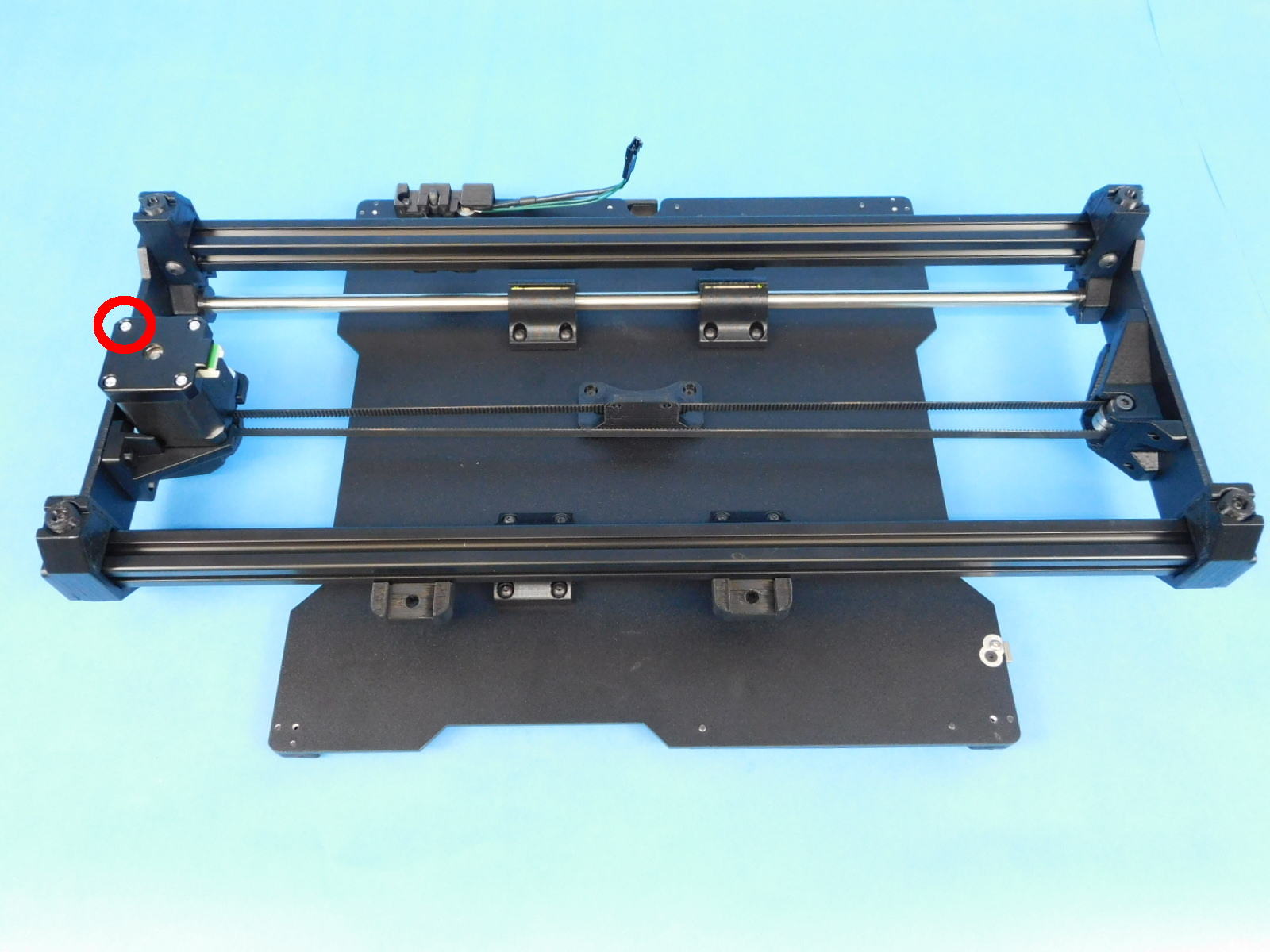
Obtain one Y-Motor Ground Extension [EL-HR0171]
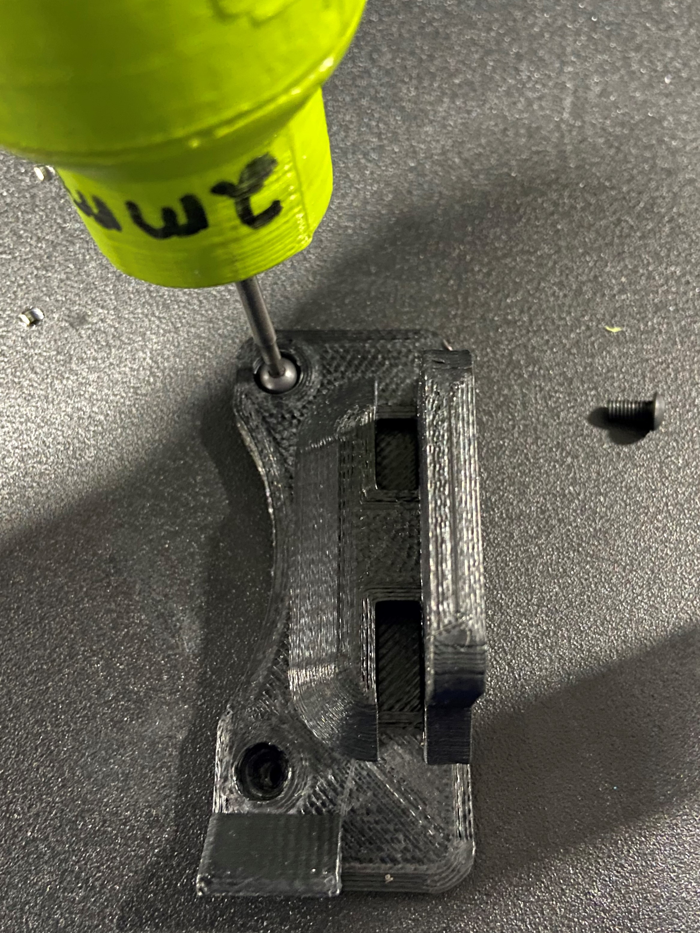
Using a P2 Phillips screwdriver, remove the highlighted fastener
Place fastener through the terminal ring of [EL-HR0171]
Place the fastener back in the hole from which it was removed and tighten securely.
Finish tightening the M3x10 screws securing the bearing holders to the bed plate, starting with all inner screws then ending with all outer screws.
Be sure the belt is centered and resting against outer side of the Y-belt mount. the Y-belt mount should be centered between the Y-motor & Idler ends. Place the Y-belt Clamp [PP-IS0088] into the grooves with the 45° angle facing out. Secure the belt clamp with M3 washers [HD-WA0038] and M3x10 BHCS [HD-BT0148].
Check the assembly to make sure the Y-axis travels smoothing with no resistance.
Assembly completed.