Open HardwareAssembly Instructions
Guides for installation and assembly of the LulzBot line of products made by FAME 3D LLC.
Guides for installation and assembly of the LulzBot line of products made by FAME 3D LLC.
The material palette for the [AS-PR0136] X-End Left Assembly:
4x- [HD-BT0116] M3x10 FHCS, Black-Oxide
14x-[HD-BT0148] M3x10 BHCS, Black-Oxide
16x- [HD-WA0038] M3 Washer, Black-Oxide
1x- [HD-BT0158] M5x12 BHCS, Black-Oxide
1x- [HD-BT0151] M5x20 SCHS, Black Oxide
1x- [HD-WA0040] M5 Washer, Black-Oxide
2x- [HD-NT0001] M3 Nyloc Nut
2x- [HD-BT0107] M2x10 SHCS
2x- [HD-WA0012] M2 Steel Flat Washer
4x- [HD-BT0012] M3x6 Set Screw
2x- [HD-BT0185] M3x16 SHCS, Black-Oxide
1x- [PP-GP0394] Belt Anchor
1x- [PP-GP0360] Z Lower Left
1x- [PP-GP0372] X Motor Chain Mount, Pro
1x- [PP-GP0156] Z Upper Top Plate
1x- [PP-GP0482] X Motor, Pro
1x- [PP-GP0358] Z Upper Left, Pro
1x- [PP-MP0225] YZ Idler, Pro
1x- [HD-Bl0023] POWERHOUSE Belt
4x- [HD-MS0411] 625-2RS Premium Two Side Rubber Sealed Bearing ABEC3
2x- [HD-RD0061] 10 mm Smooth Rod, Stainless Steel, 405mm
2x- [HD-MS0033] GT2, 16 Teeth, timing pulley, AL
1x- [EL-MT0029] NEMA 17 Stepper Motor, Moons' - NOT INCLUDING wire harness
1x- [EL-MT0056] Motor, Moons 4118S-08P-07RO
1x- [EL-SW0022] SWITCH BASIC SPDT

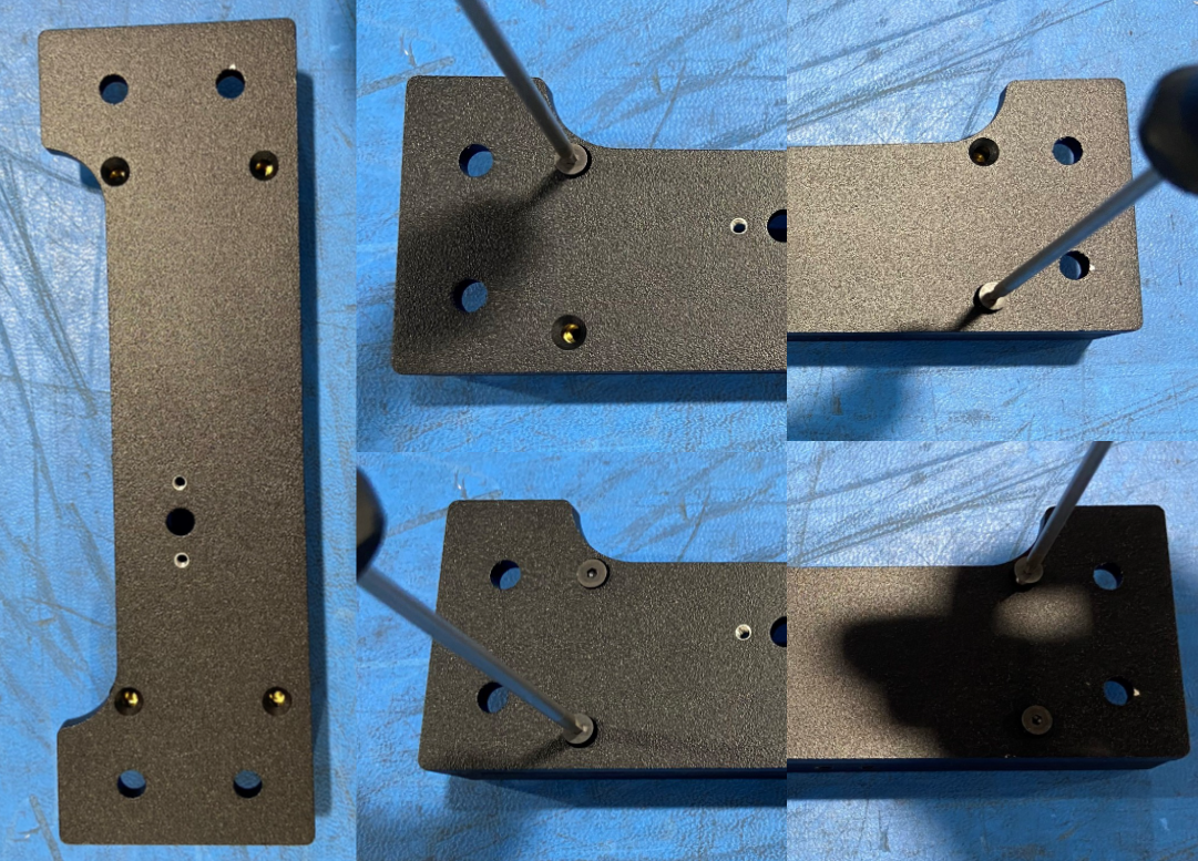
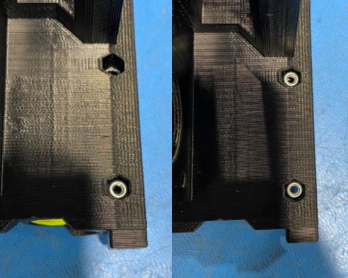
Place two M3 Nyloc Nuts [HD-NT0001] in the two hex holes on the X Motor [PP-GP0482] as shown. Then while holding one of the nyloc nuts in the hole fasten a M3x16 SHCS [HD-BT0185] with a M3 washer [HD-WA0038], repeat with second nyloc nut.
Don't Tighten all the way
Slide one GT2 timing pulley [HD-MS0033] on to the shaft of the moons motor [EL-MT0029] using the provided jig and fasten one of the set screws on the flat side of the shaft and fasten the other set screw to the side of the shaft.
Torque to 3 in*lbs.
Fasten the moons motor to the x-end motor using 3x M3X10 BHSC [HD-BT0148] with M3 washer [HD-WA0038].
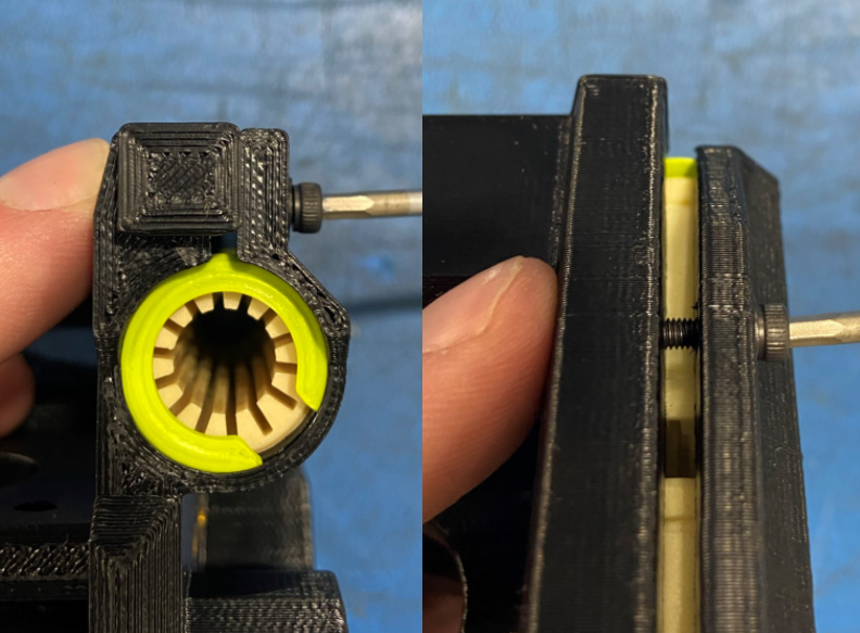
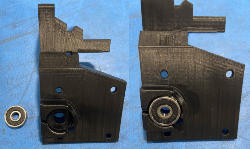
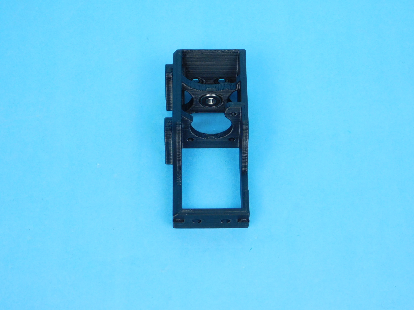
Insert a sealed rubber bearing [HD-MS0411] into X Motor Chain Mount [PP-GP0372] and fasten it to the X Motor using 4x M3X10 BHSC [HD-BT0148] with M3 washer [HD-WA0038].
Install the Timer Pulley [HD-MS0033] on to the motor shaft [EL-MT0056], being sure to tighten the set screws onto the flat part of the shaft. Torque down to 3 in*lbs.
Place POWERHOUSE Belt [HD-Bl0023] over the YZ Idler [PP-MP0225] with the teeth facing up, then using 1x M5x20 SCHS [HD-BT0151] secure 2x Sealed Rubber Bearing [HD-MS0411] between the two walls of YZ Idler.
Torque to 5 in*lbs
Insert a Sealed Rubber Bearing [HD-MS0411] into the designated spot on the Z-lower left [PP-GP0360].
Insert the belt with the YZ idler into the slot of top of the Z-lower left, making sure that the head of the fastener on the YZ idler is facing away from the motor.
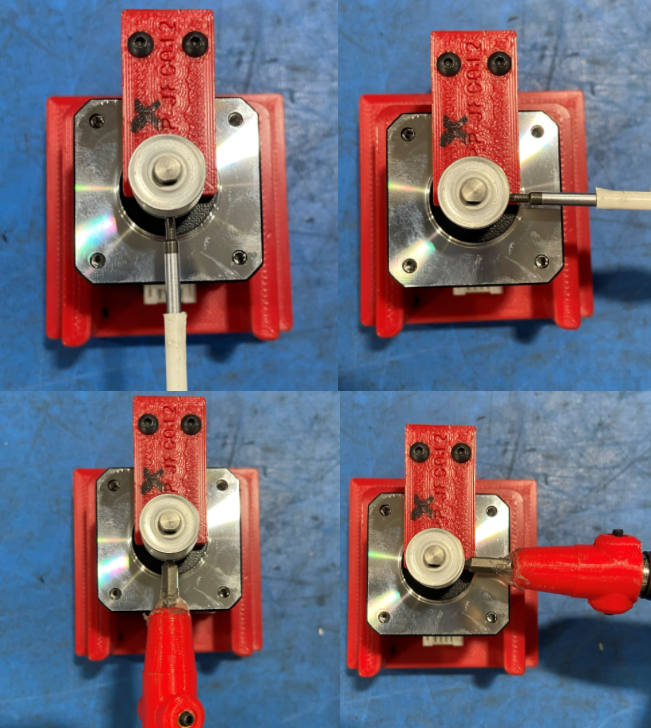
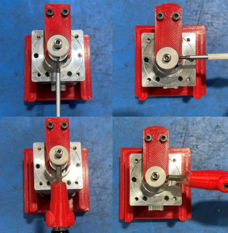
Insert the motor's shaft [EL-MT0056] into the sealed bearing making sure that you go through the belt loop. Check to ensure that the motor connector is facing away form the belt or towards the bottom of the assembly. Fasten the motor with 3x M3X10 FHCS [HD-BT0148] with M3 washers [HD-WA0038].
Note: Use the red and black ball joint drivers to fasten the motor to the Z lower left to ensure that the fasteners do not go in crooked.


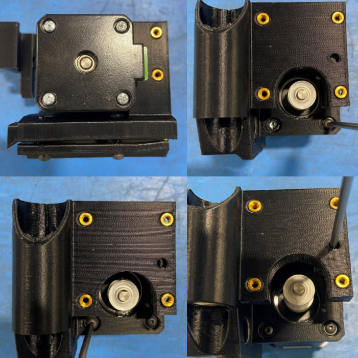
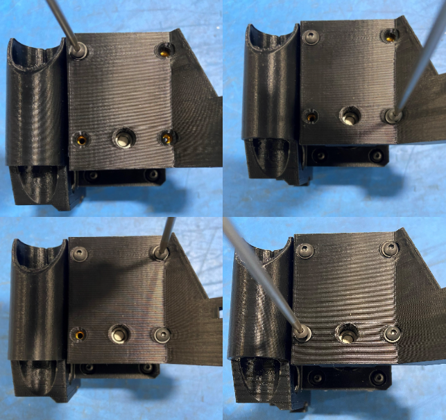
Using 4x M3x10 FHCS [HD-BT0116] fasten the Z Upper Left [PP-GP0358] to the Z Upper Top Plate [PP-GP0156]
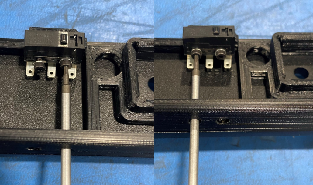
Bend the Basic Switch [EL-SW0022] to 90° using the jig as shown
Making sure once the tabs are bent, point up and to the right of the switch, that the button sensor is towards the back of the switch
Install the bent Basic Switch to the Z Upper Left assembly using 2x M2x10 SHCS [HD-BT0107] with M2 Washers [HD-WA0012]
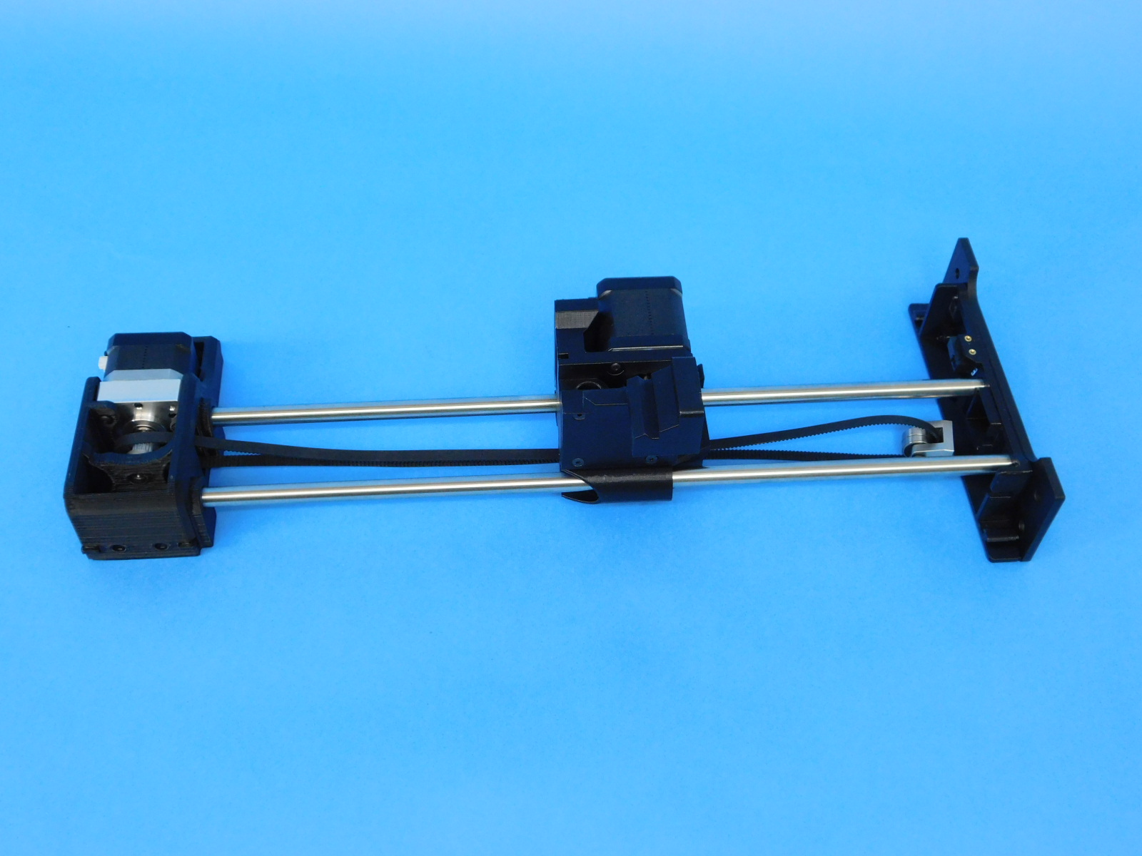
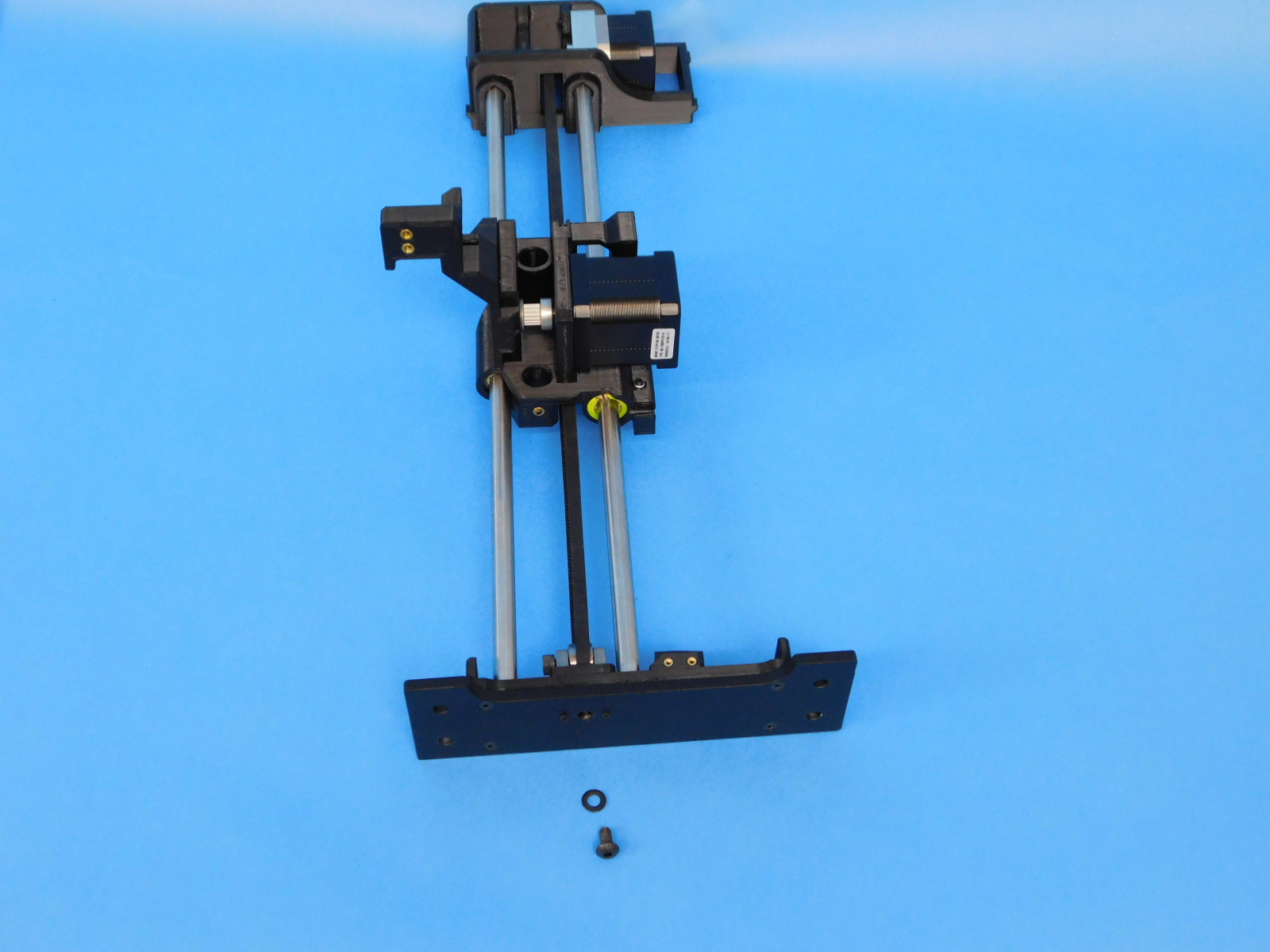
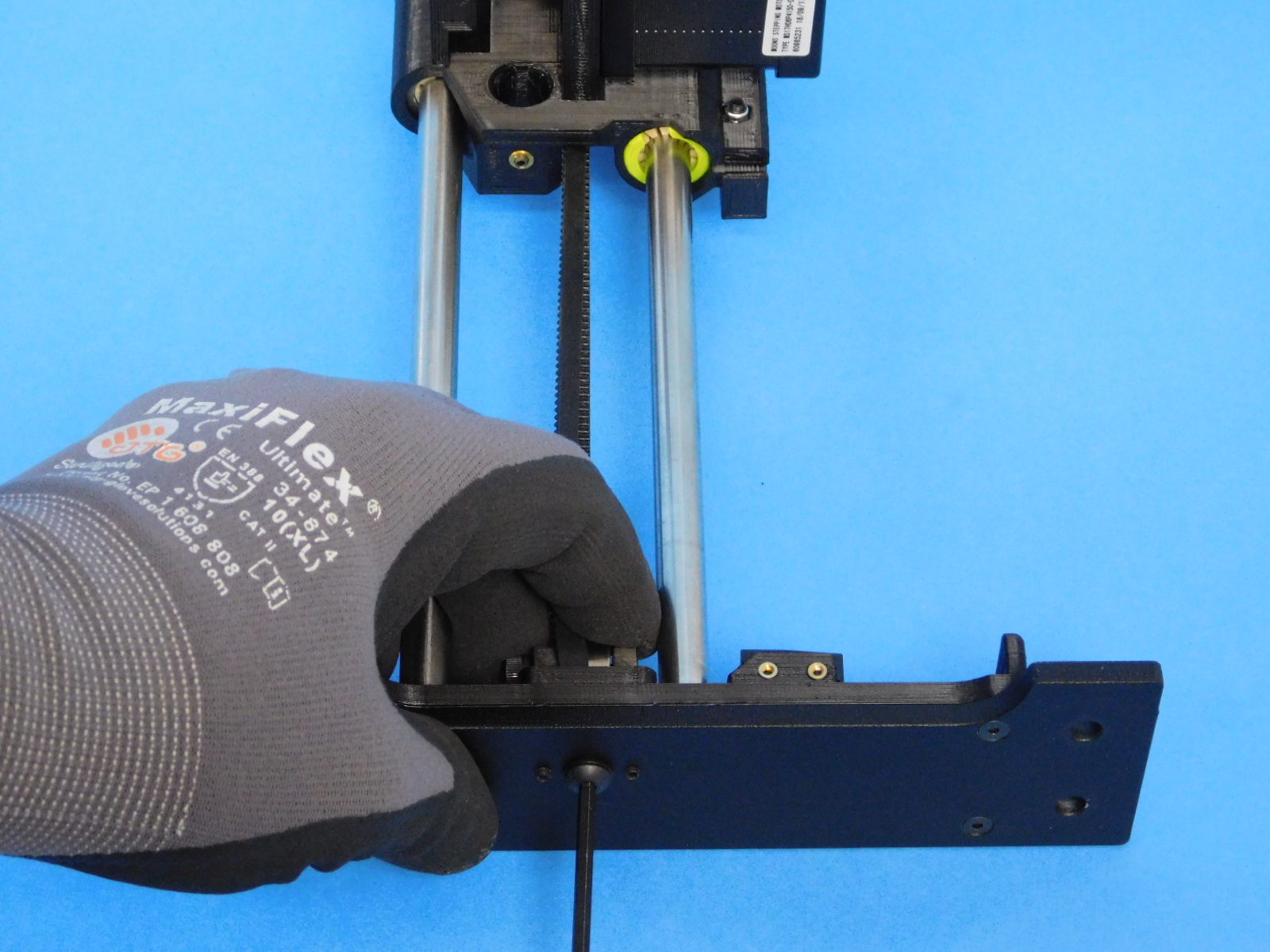
Slide 2x 10mm Smooth Rods [HD-RD0061] into the X-End Motor and insert each end into the designated spots on the Z-upper left and Z-lower left.
Place the YZ idler into its designated slot on the Z-upper and fasten it using 1x M5X10 BHSC [HD-BT0073] with a M5 washer [HD-WA0040].
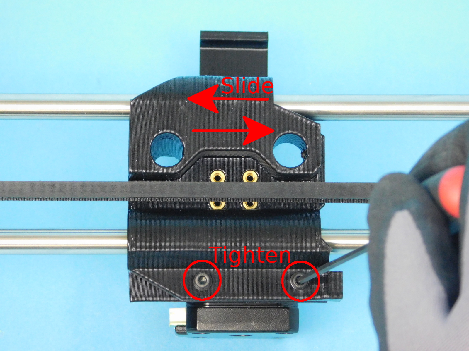
Tighten the Z-Axis compression hardware while moving the X-Motor End back and forth through the range of travel.
Tighten until bearing doesn't wobble on rod but still slides freely.
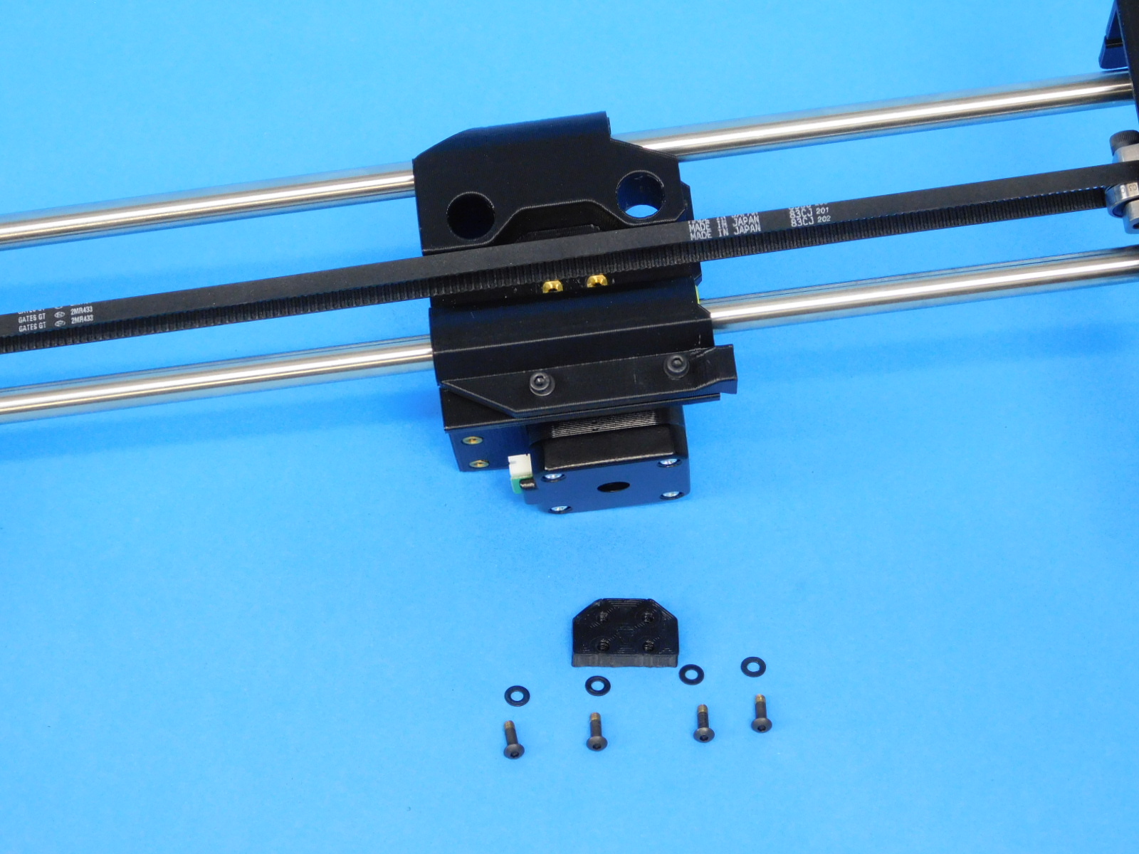
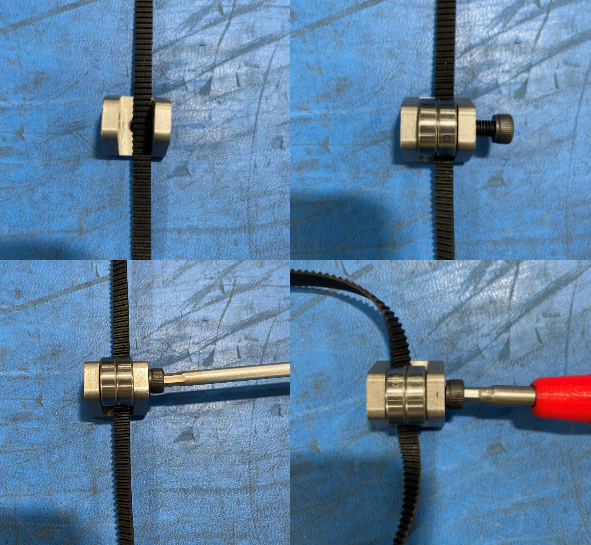
Place the belt anchor [PP-GP0394], groove side face towards the teeth on the belt, and fasten with 4x M3X10 BHCS [HD-BT0148] with M3 washers [HD-WA0038]. Torque the 4x fasteners to 5 in*lbs.