Open HardwareAssembly Instructions
Guides for installation and assembly of the LulzBot line of products made by FAME 3D LLC.
Guides for installation and assembly of the LulzBot line of products made by FAME 3D LLC.
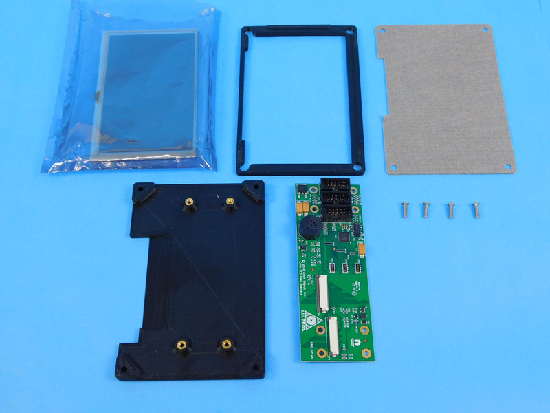
1x [EL-MS0552] Display, 5" with resistive touch panel
4x [HD-BT0234] M3x10mm BHCS, SST
1x [PC-BD0117] Color_LCD_ Board CLCD2 Rev B
1x [PP-FP0157] LCD Ground Spacer, conductive foam
1x [PP-GP0385] LCD center
1x [PP-GP0386] LCD Back
Be sure that you are properly grounded before starting this assembly.
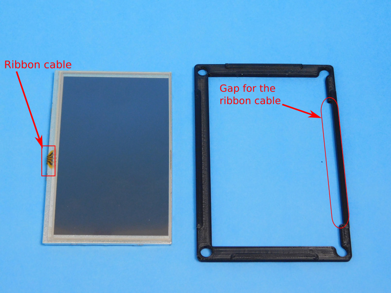
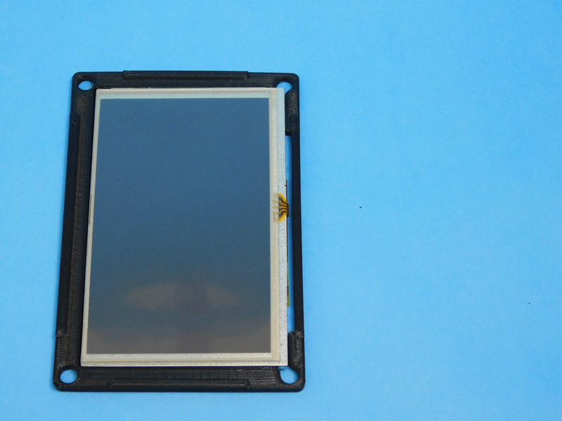
Carefully insert the LCD Touchscreen [EL-MS0552] into the LCD center [PP-GP0385]. Be careful that the ribbon cable is inserted on the side with the gap in the LCD center.
The LCD touch screen should be a little tight but do not force it in to the LCD center.
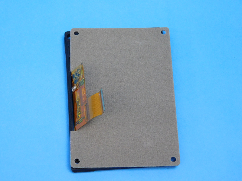
Fit the [PP-FP0157] LCD Ground Spacer, conductive foam onto the back of the LCD touch screen, careful to make sure that the ribbon cable fits into the gap of the foam. This will create the LCD stack.

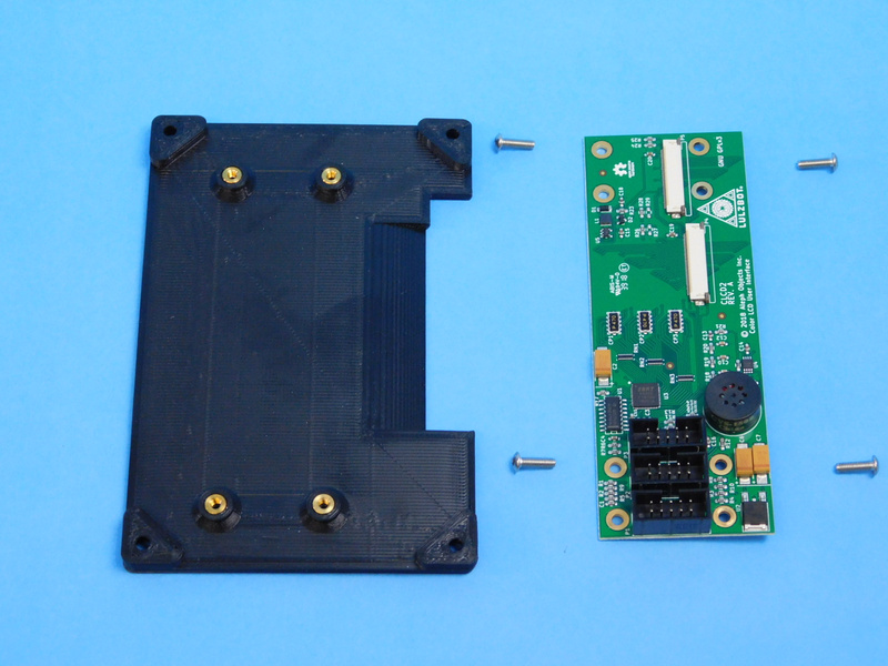
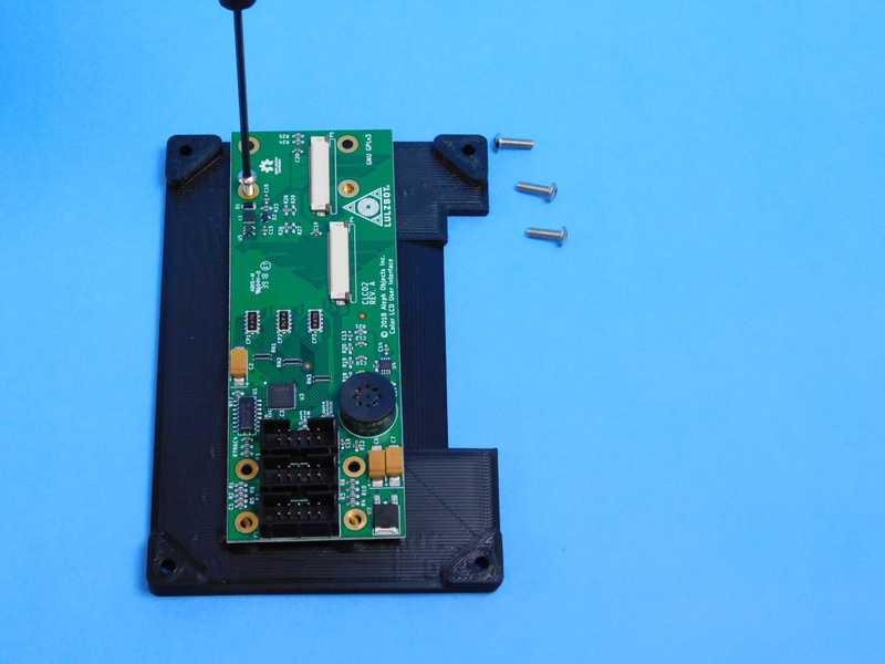
Using the 4x M3x10mm BHCS SST [HD-BT0234] to mount the Color_LCD_ Board CLCD2 Rev B [PC-BD0117] to the LCD back [PP-GP0386]. The screws should be sticking out past the bottom of the LCD back.
Note that the top of the LCD board should line up with the top of the LCD back. This will ensure that the LCD ribbon cable properly lines up with the LCD board connector.
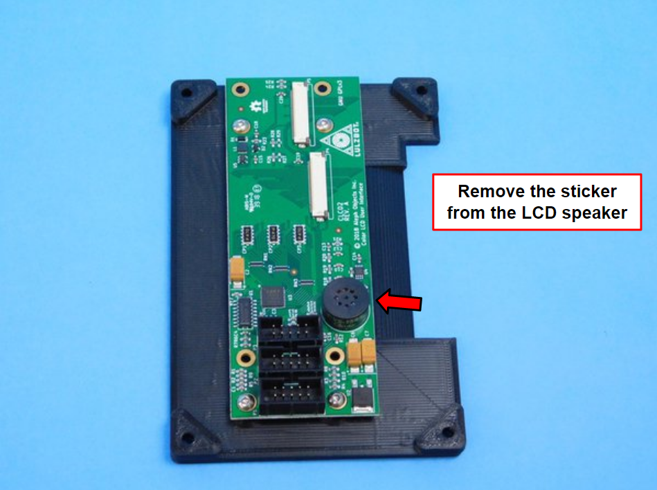
Make sure to remove the yellow sticker from the LCD speaker
Carefully place the LCD stack with the ground foam against the fasteners that are sticking out from the bottom of the LCD back.
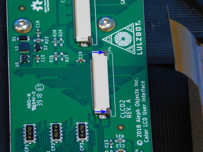
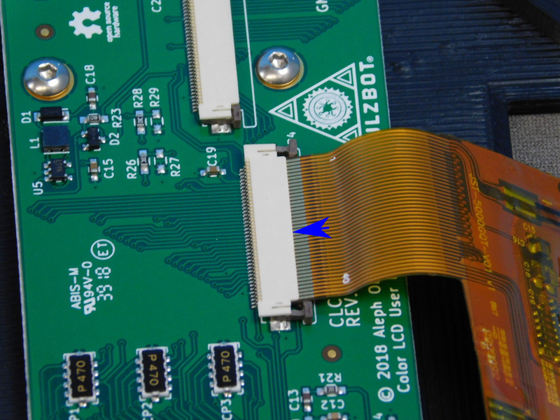
Using a fingernail, slide the gray tabs out from the connector so that the connector is now in a open state.
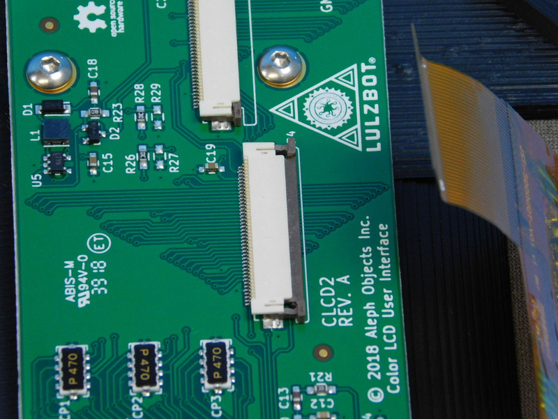
Slide the ribbon cable into the connector so that brass connections on the connector are fully concealed beneath the connector.
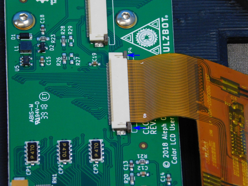
Push down on both gray tabs so that the connector is now in the closed state and the ribbon is fully secured.
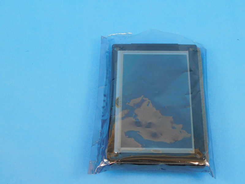
When finished, slide the LCD assembly into the ESD bag that the touch screen originally was received in.

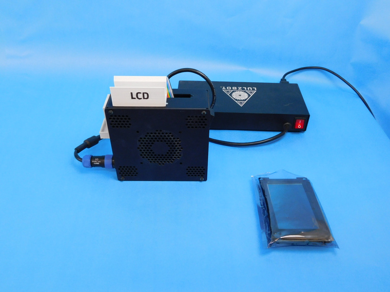
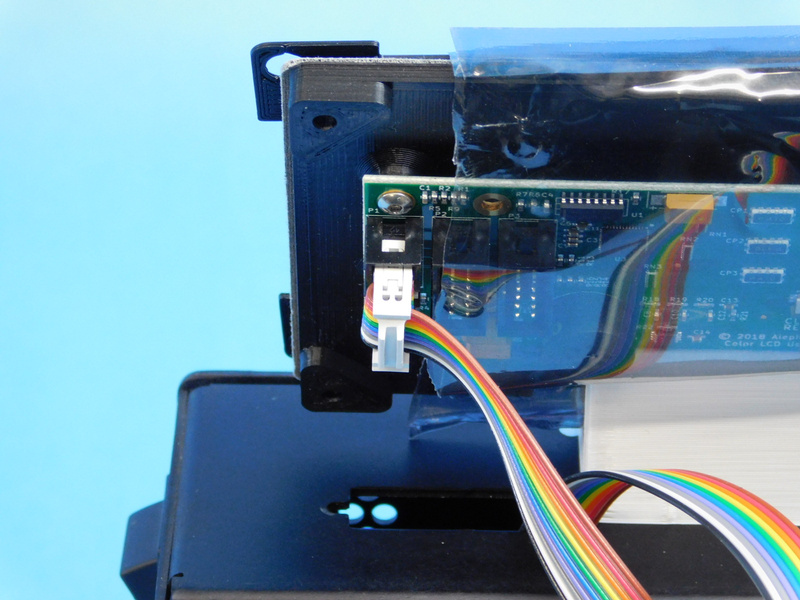
Plug the rainbow ribbon cable into the back of the LCD board into the bottom connection.
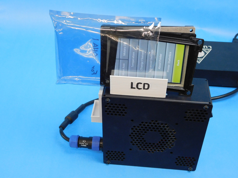
As you are turning on the device, hold your finger to the LCD display inorder to test the screen calibration. You should see it go gray for a second before going to the default screen with a message saying that it was unable to read a USB.
Make sure that the sound is functioning correctly by navigating to Menu -> About Printer. A short chime should play at this point indicating that the sound is working correctly.