Open HardwareAssembly Instructions
Guides for installation and assembly of the LulzBot line of products made by FAME 3D LLC.
Guides for installation and assembly of the LulzBot line of products made by FAME 3D LLC.
Gather Parts:
Gather Tools: 3mm Hex driver Squaring fixture
Instrictions
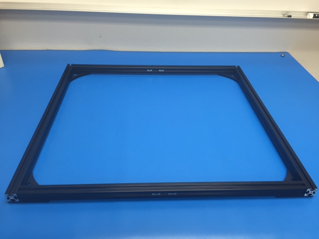
Front frame
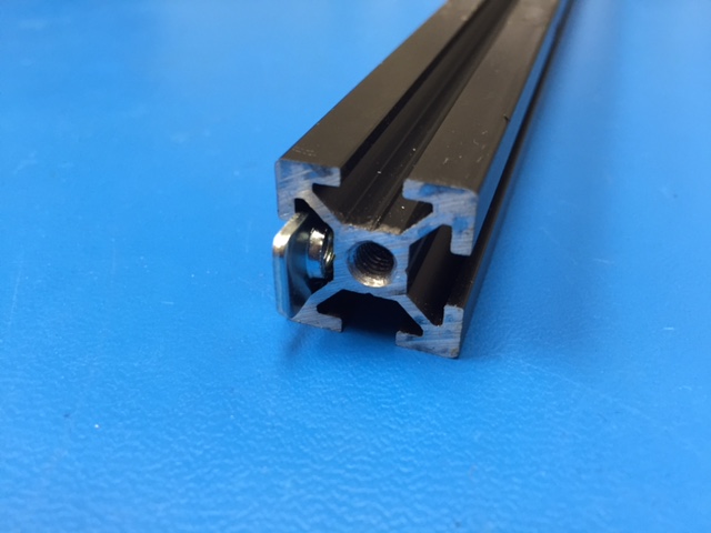
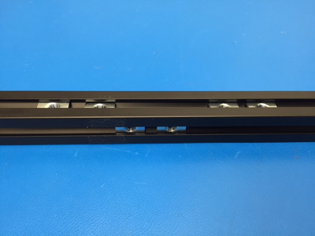
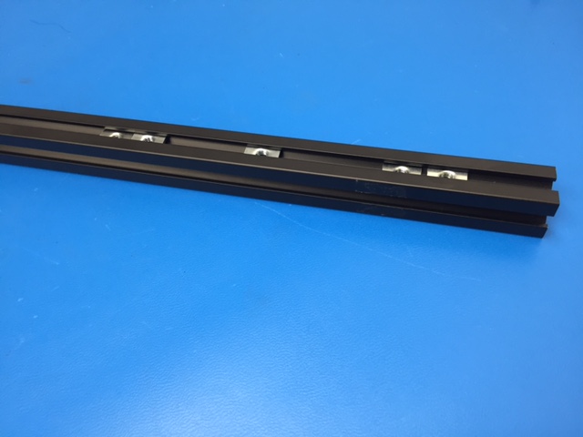
Install four (4) T-Nuts into one side of a 500mm aluminum strut (tapped on one end), position the T-Nuts so there are two (2) at each end of the strut; repeat for a second 500mm (tapped on one end) strut
Install four (4) T-Nuts into one side of a 510mm aluminum strut, position the T-Nuts so there are two (2) at each end of the strut; repeat for a second 510mm strut
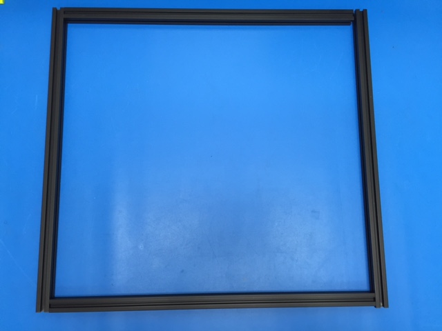
Place the four (4) struts with the T-Nut side up
Arrange each of the 500mm struts parallel to each other and with their threaded ends at the same end oriented toward yourself
Place each of the 510mm struts between the 500mm struts so the 510mm struts align with the side and end of the 500mm strut (T-Nut sides should still be up)
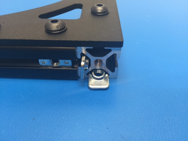
Insert two (2) T-Nuts into the inside slot of the bottom 510mm strut. Use two (2) M5X10 BHCS to install two y chassis mounts, these will be used later in the assembly.
Insert two (2) T-Nuts into the top side slot of the top 510mm strut, these will be used later in the assembly.
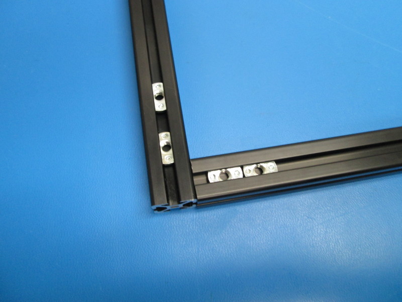
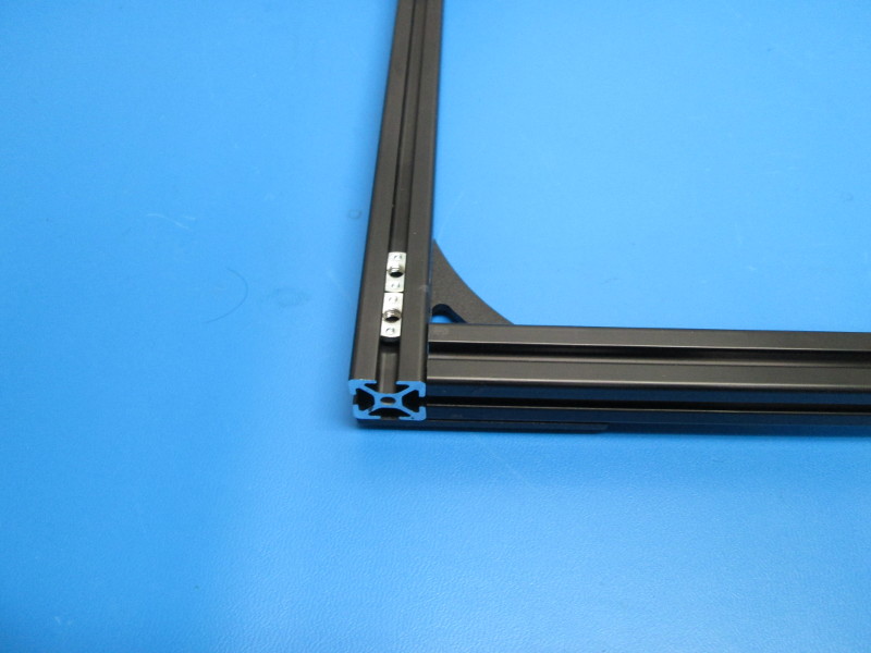
Place a corner gusset at each of the strut intersections; Loosely secure each gusset with (4) M5X10 BHCS and (4) M5 black washer.
Place one corner joint into a known square location, such as a squaring table; ensure the corners are square and the ends are flush; Secure each of the gusset screws are tightened to 40 in-lbs; repeat this for each corner.
Back Frame
Install four (4) T-Nuts into one side of a 500mm aluminum strut (tapped on one end), position the T-Nuts so there are two (2) at each end of the strut; repeat for a second 500mm strut (tapped on one end).
Install four (4) T-Nuts into one side of a 510mm aluminum strut, position the T-Nuts so there are two (2) at each end of the strut.install five (5) T-Nuts on the second 510mm strut.
Place the four (4) struts with the T-Nut side up
Arrange each of the 500mm struts parallel to each other and with their threaded ends at the same end oriented toward yourself
Place each of the 510mm struts between the 500mm struts so the 510mm struts align with the side and end of the 500mm strut (T-Nut sides should still be up)
Insert two (2) T-Nuts into the inside slot of the bottom 510mm strut. Use two (2) M5X10 BHCS to install two y chassis mounts, these will be used later in the assembly.
Insert two (2) T-Nuts into the top side slot of the top 510mm strut, these will be used later in the assembly
Place a corner gusset at each of the strut intersections; Loosely secure each gusset with (4) M5X10 BHCS and (4) M5 black washer.
Place one corner joint into a known square location, such as a squaring table; ensure the corners are square and the ends are flush; Secure each of the gusset screws are tightened to 40 in-lbs; repeat this for each corner.


Gather parts:
10x- M5x10 BHCS
10x- M5 black washer
4x- M5 T-Nut
Place the Front frame assembly gussets down with the frame top side (top side has the threads in the extrusion center holes) oriented toward you
Install the Z top drive onto to the frame side near your right; using one (1) M5X10 BHCS and one (1) M5 Black washer for each side. Tighten screws down to no more that 6 in-lbs.
Install the Z top drive onto the frame side near your left using one (1) M5X10 BHCS and one (1) M5 Black washer for each side. Tighten screws down to no more that 6 in-lbs.
Rotate the frame 180 degrees; Insert two (2) T-nuts to each the bottom slot and inside slot in the top side of each of the Left and Right extrusions
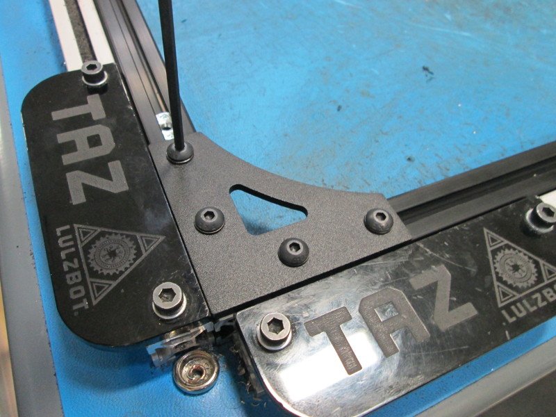
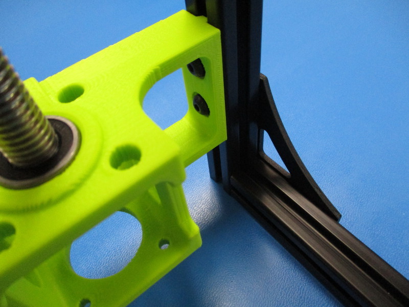
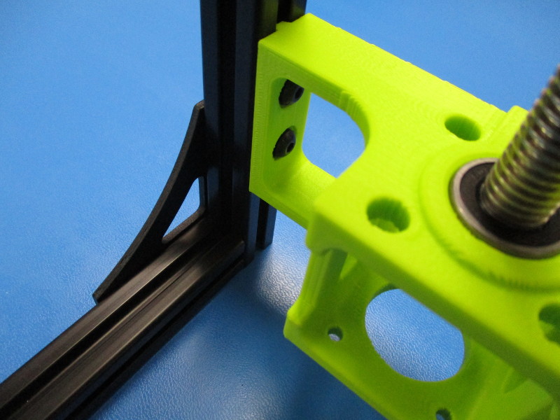
Install the X End Right assembly on the left side of the frame; use two (2) M5X10 BHCS and two (2) M5 Black washer to secure the Z motor mount in place.
Install the X End Left assembly on the right side of the frame; Use two (2) M5X10 BHCS and two (2) M5 Black washers to secure the Z motor mount in place.
Attach the Z lowers to the back frame; use two (2) M5x10 BHCS and two (2) M5 black oxide washers.


Gather parts:
8x- M5x10 BHCS
8x- M5 black washer
3x- M5 T-Nut
Rotate the work in progress 180 degrees; place the Front frame assembly on top of the Z tops and motor mounts. Make sure the threaded side of the frame is facing toward you.
Slide one (1) T-nut into each side of the front frame assembly top extrusions (bottom slot shown) ; Make sure the third T-nut is captured between the top drive and the Z motor mount.
Secure the frame to the Z top drive using three (3) M5X10 BHCS and three (3) M5 Black washers
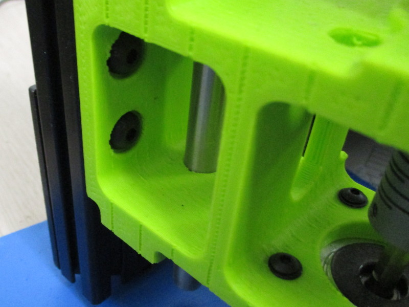
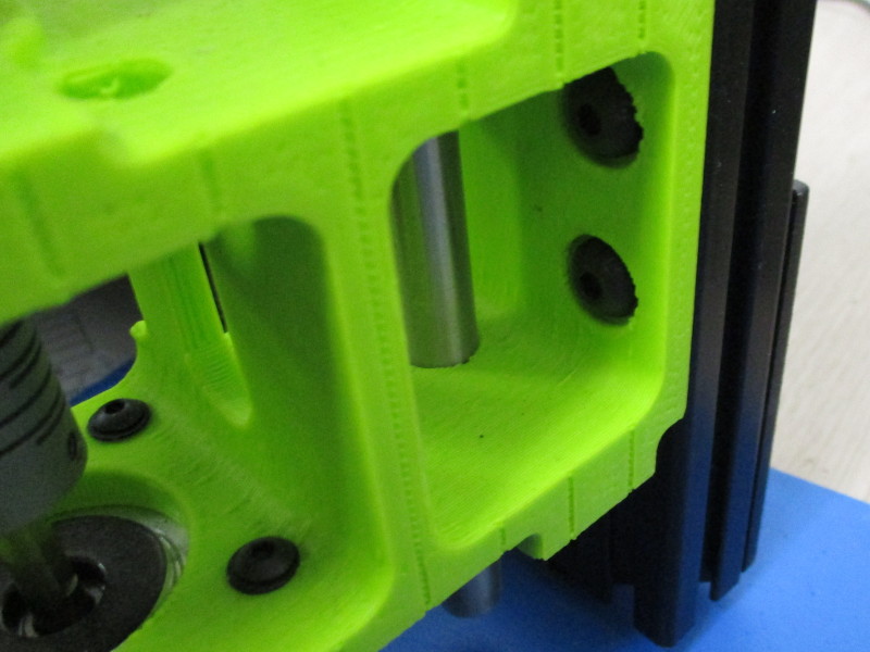
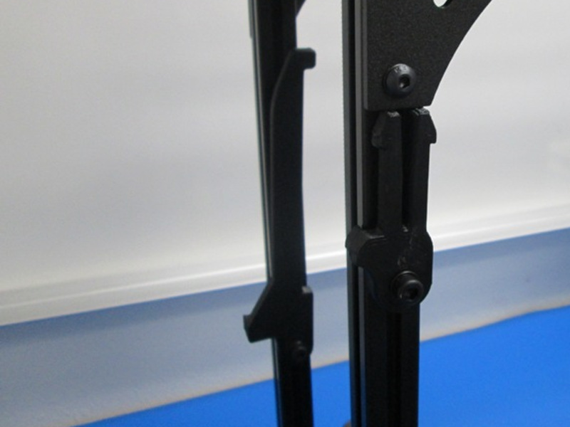
Carefully flip the frame assembly onto its front, and rotate 180 degrees and install one (1) T-nut in the top side of the X end Left extrusion; Align T-Nuts with the mount holes in the motor mount.
Use two (2) M5X10 BHCS and two (2) M5 Black washers per side with the T-nuts to secure the Z motor mount in place.
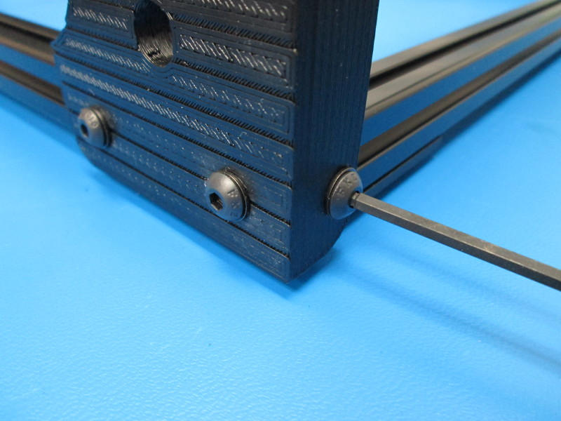
Carefully take the frame to a flat surface and use a square to ensure the frame is perpendicular to the flat surface.
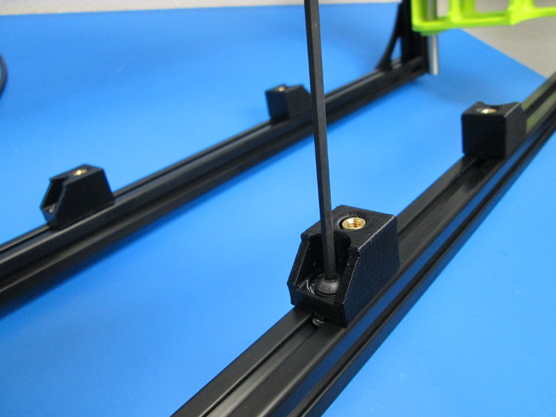
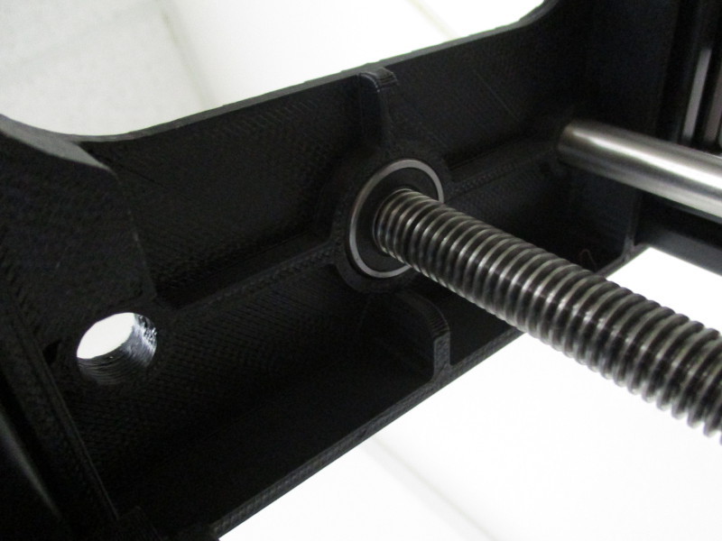
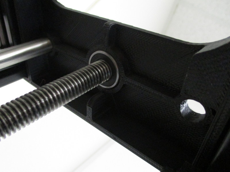
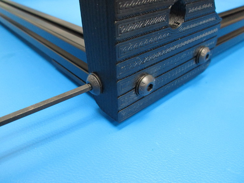
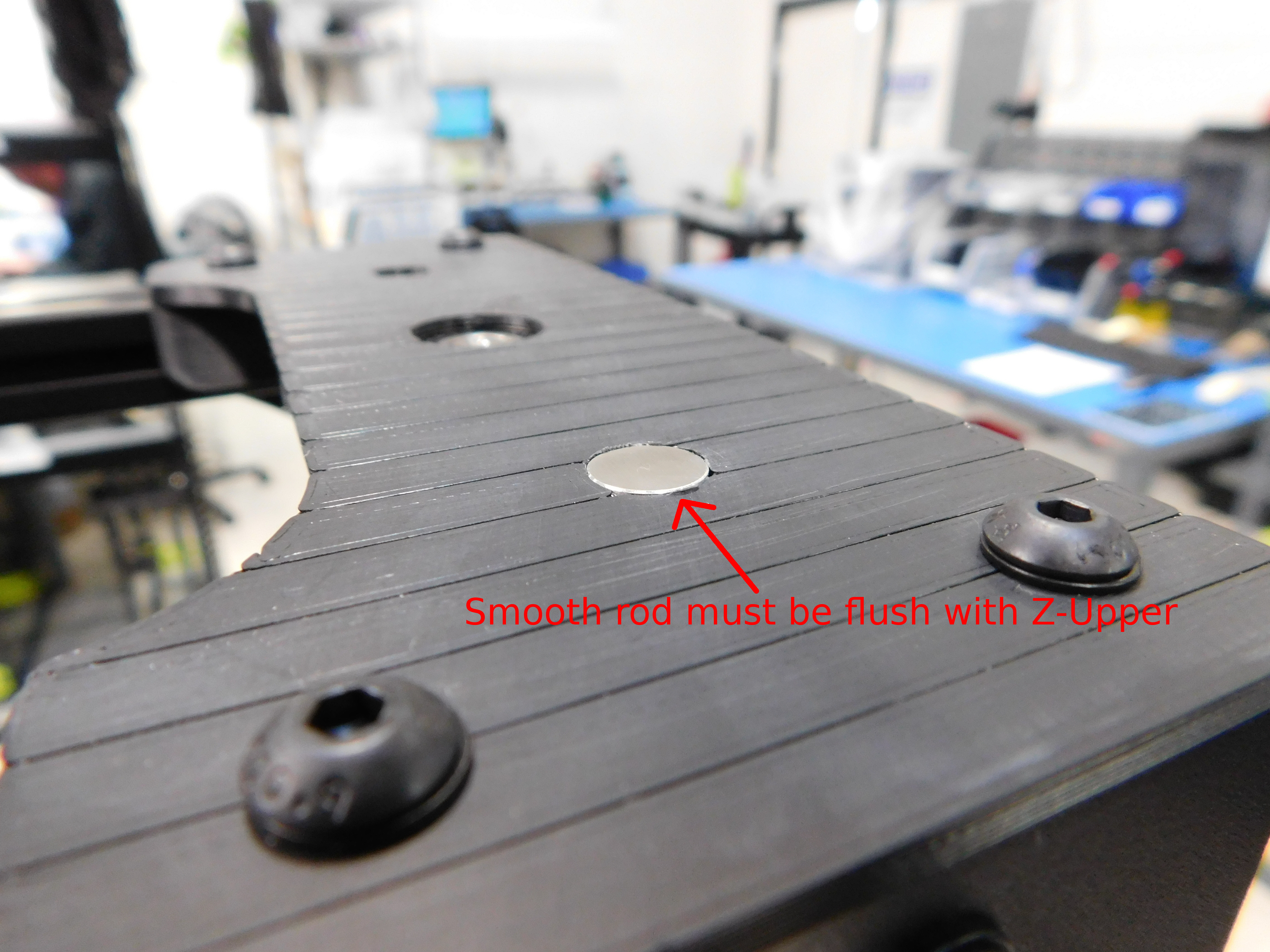
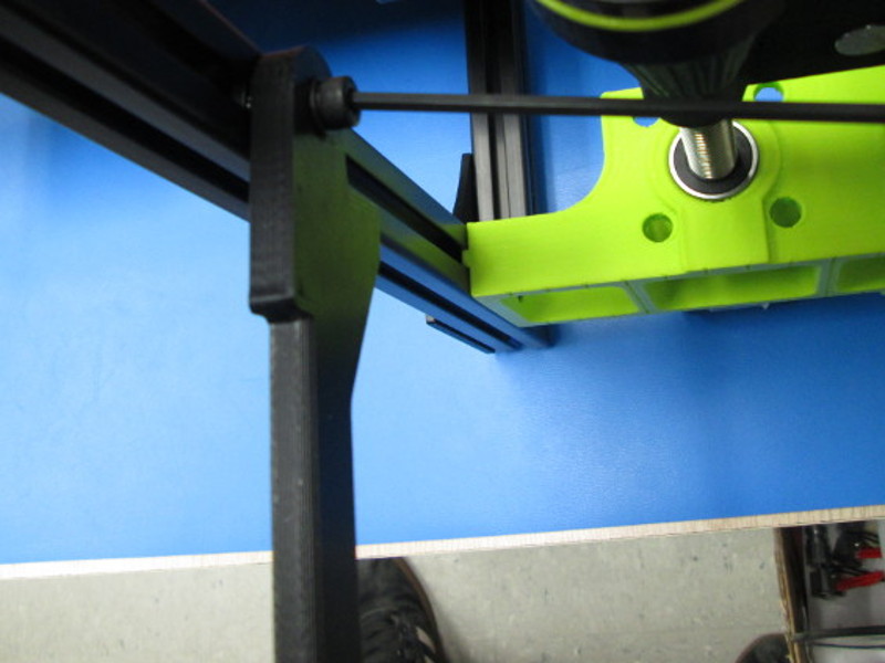
Ensure the top of both smooth rods are flush with the Z-Uppers.
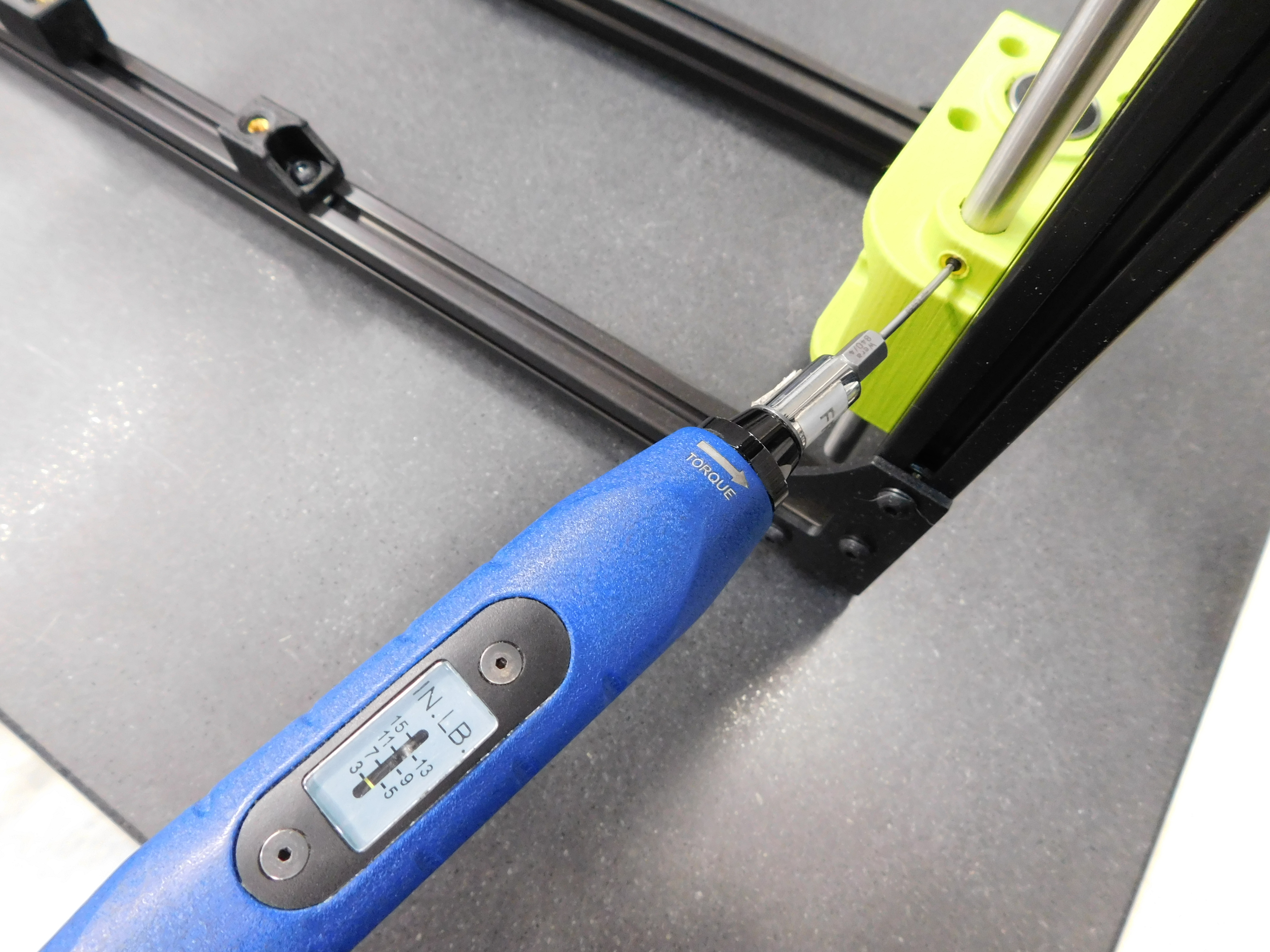
Torque both set screws on the Z-Lower motor mounts to 3 in*lbs.

Gather parts:
2x- M5x12 SHCS
2x- M5 black oxide washer
Instructions:
Install the spool arm as shown using one M5X12 SCHS and an M5 black washer . Tighten hand tight.
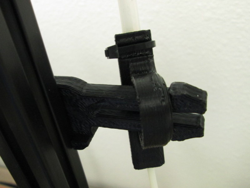
Install the feed tube spinner as shown.
Gather parts:
4x-Y chassis mounts
4x- M5 black oxide washer
4x- M5x10 BHCS
Install four (4) Y chassis mounts onto the front (2) and back (2) lower extrusions (top slot), tapered side oriented toward the outsides of the frame using four (4) M5x10 BHCS and four (4) M5 black washers (they attach to the captured T-Nuts free floating in the extrusion), leave screws loose until later in the assembly.
Slide the left Y chassis mounts out to the left side of the frame, right side mounts toward the right side of the frame