Open HardwareAssembly Instructions
Guides for installation and assembly of the LulzBot line of products made by FAME 3D LLC.
Guides for installation and assembly of the LulzBot line of products made by FAME 3D LLC.
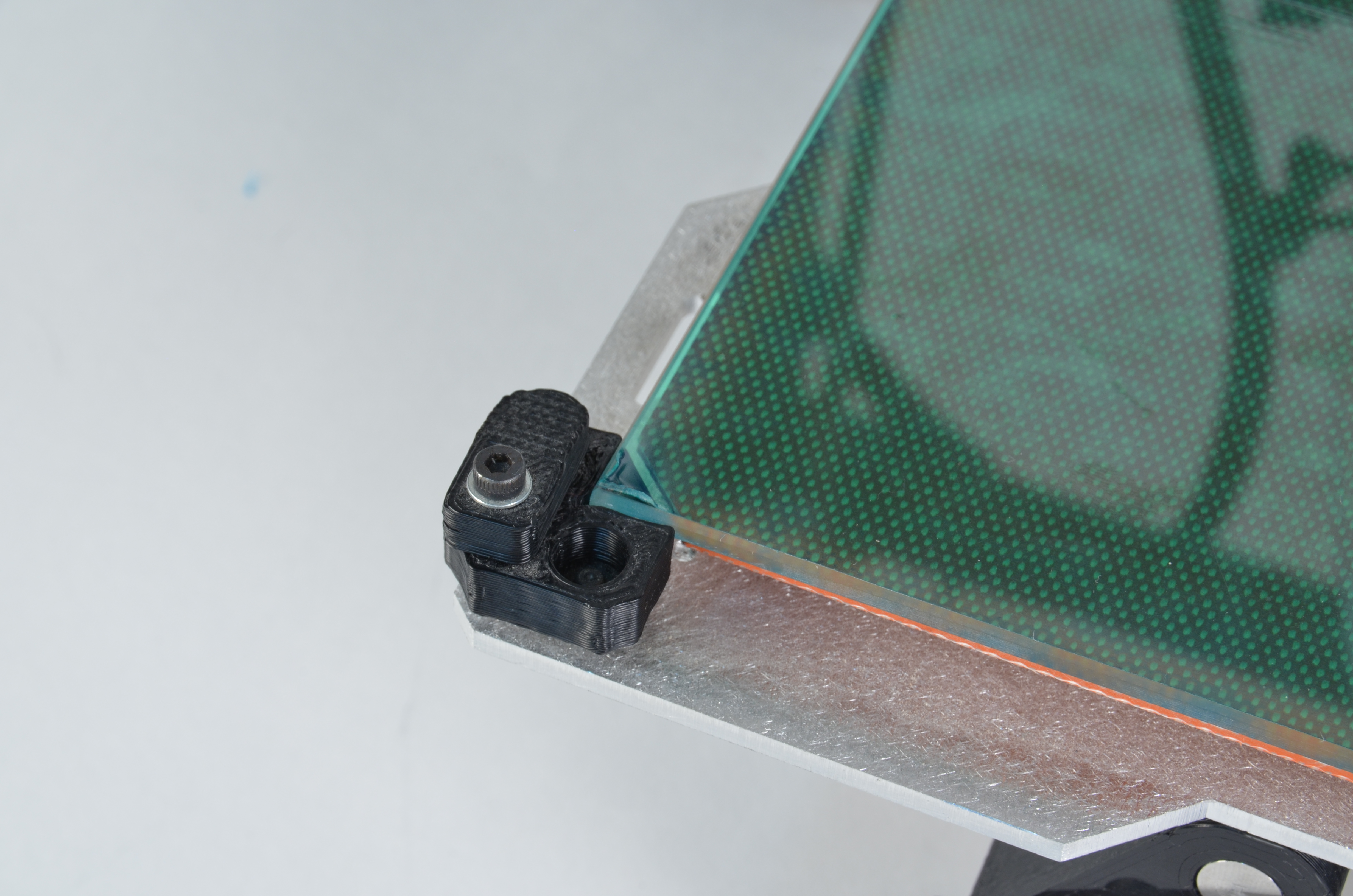
4 new heated bed corners Available at:
http://download.lulzbot.com/TAZ/3.0/production_parts/printed_parts/stl/bed_corner-2.5.stl
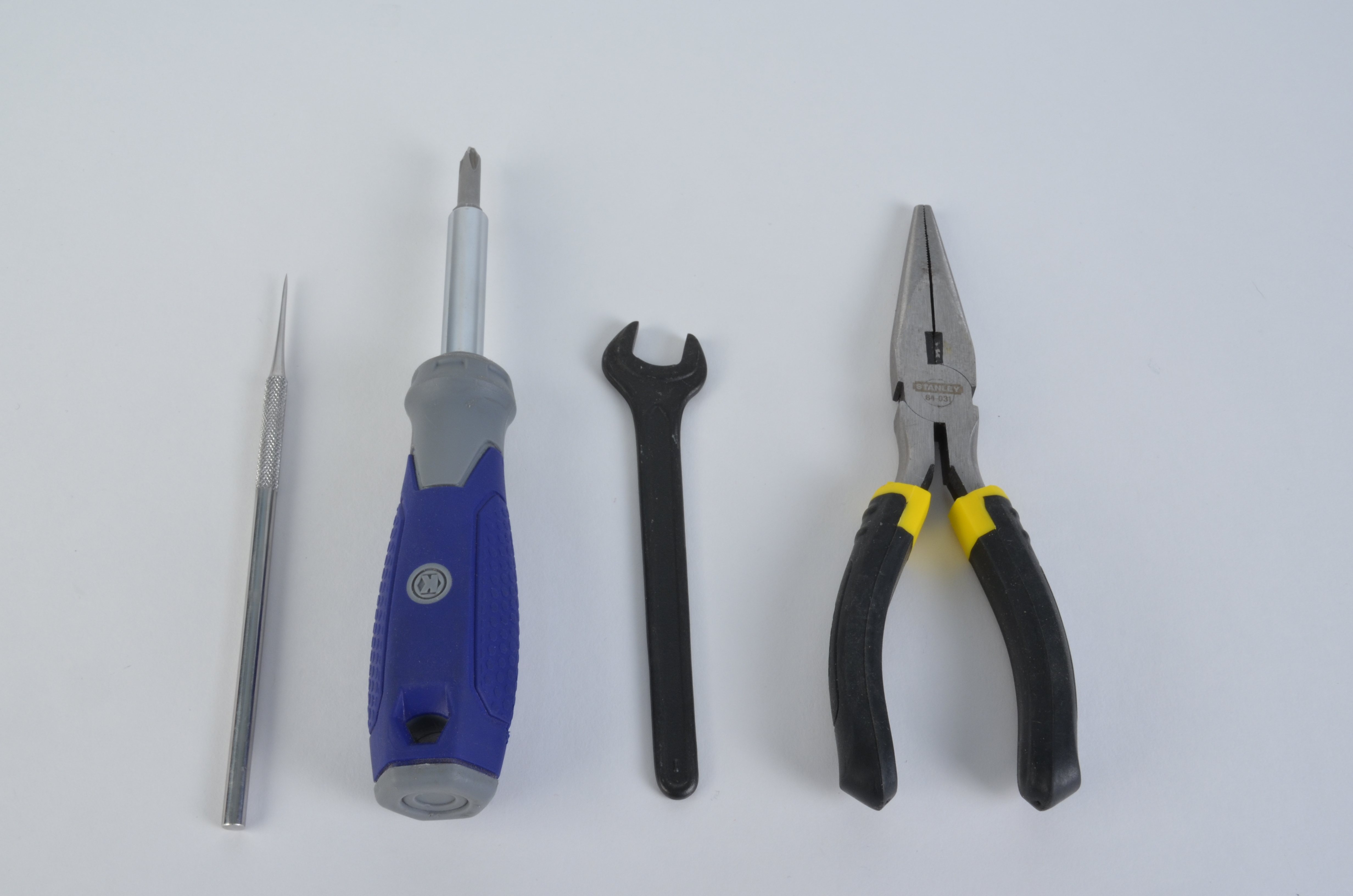
TAZ 1 users will need the following:


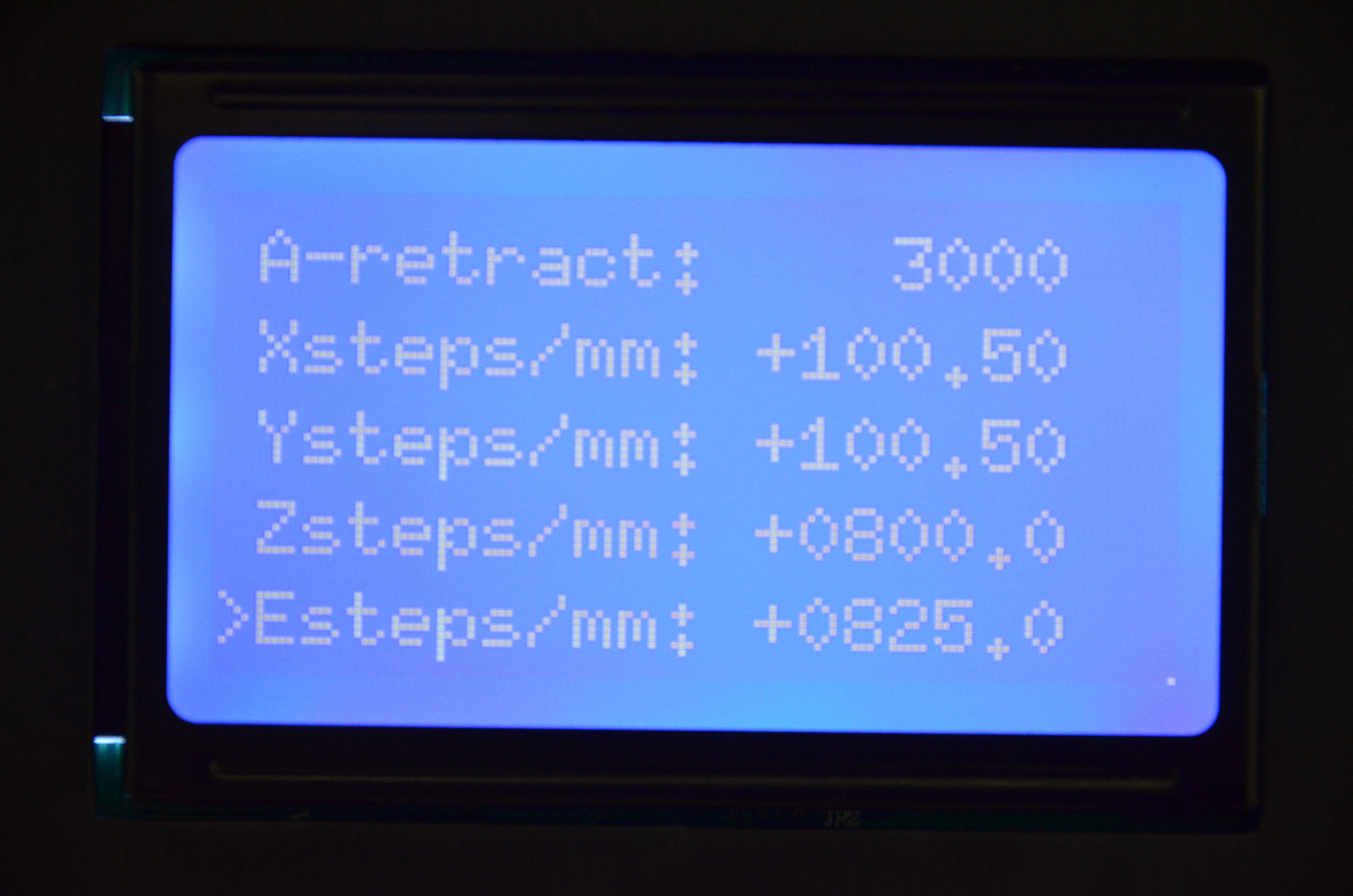
If you do not have the paper work or cannot determine your extruder steps per unit stop and contact Lulzbot Technical Support for help by sending an email to support@lulzbot.com


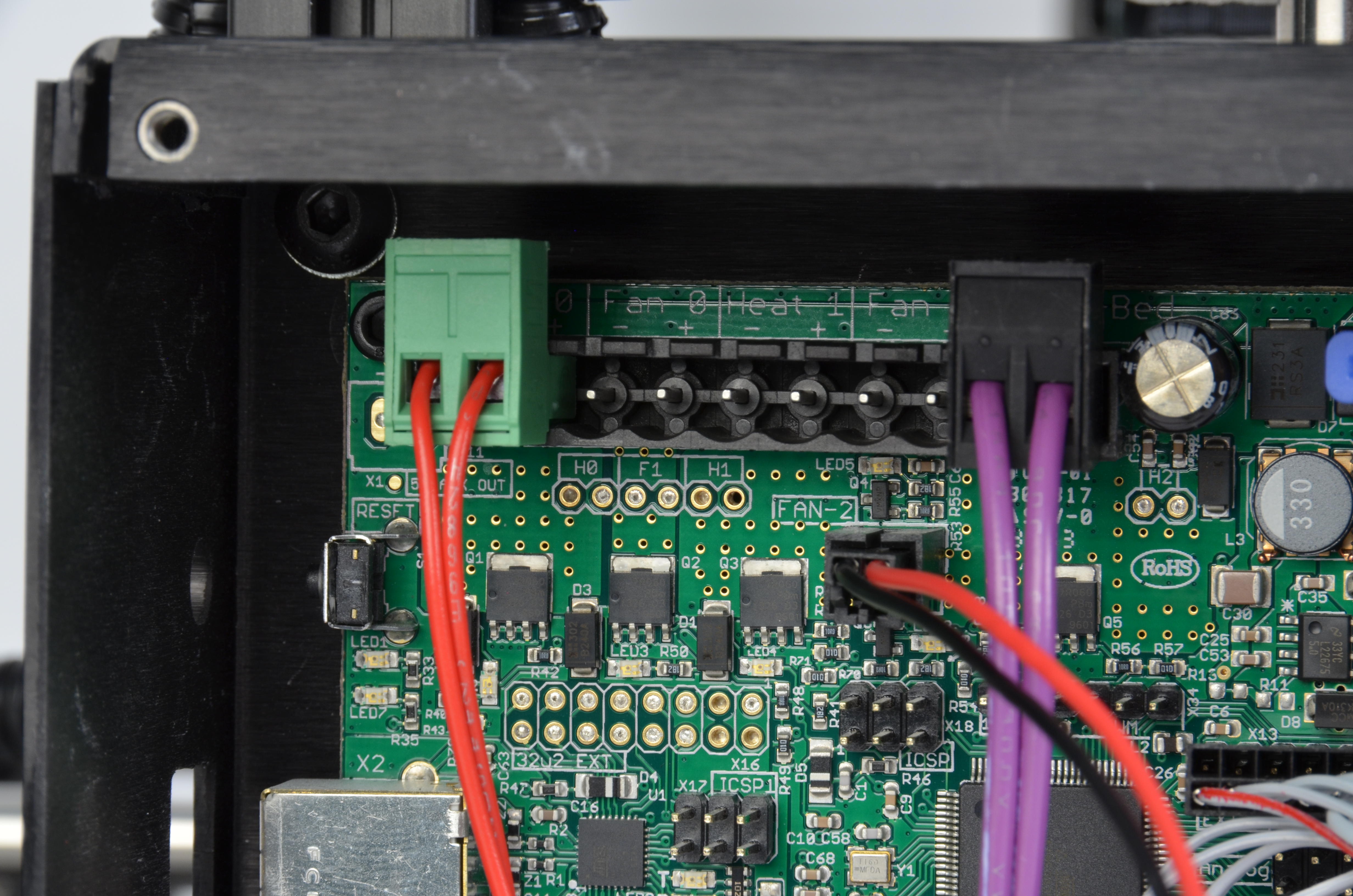
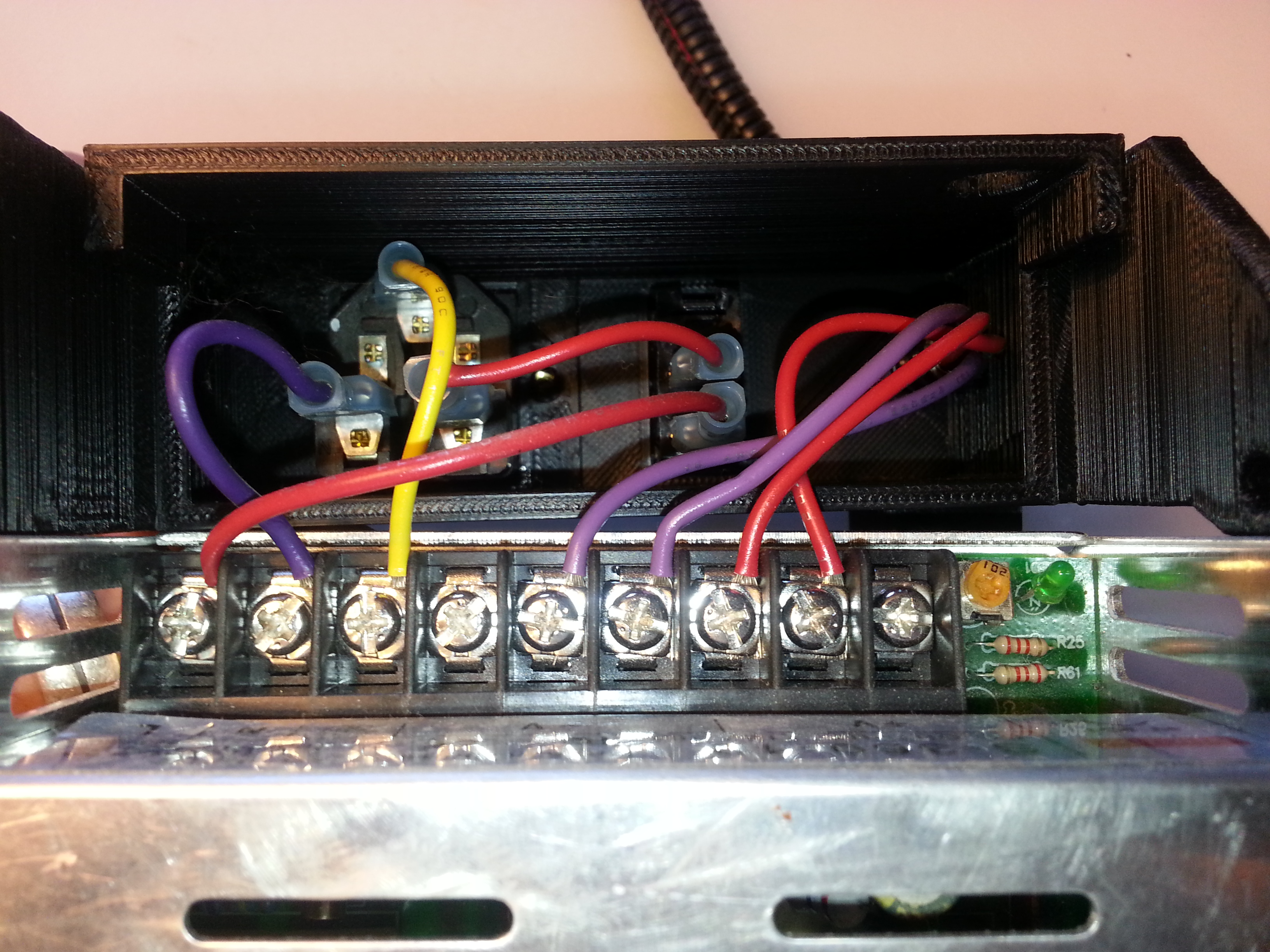
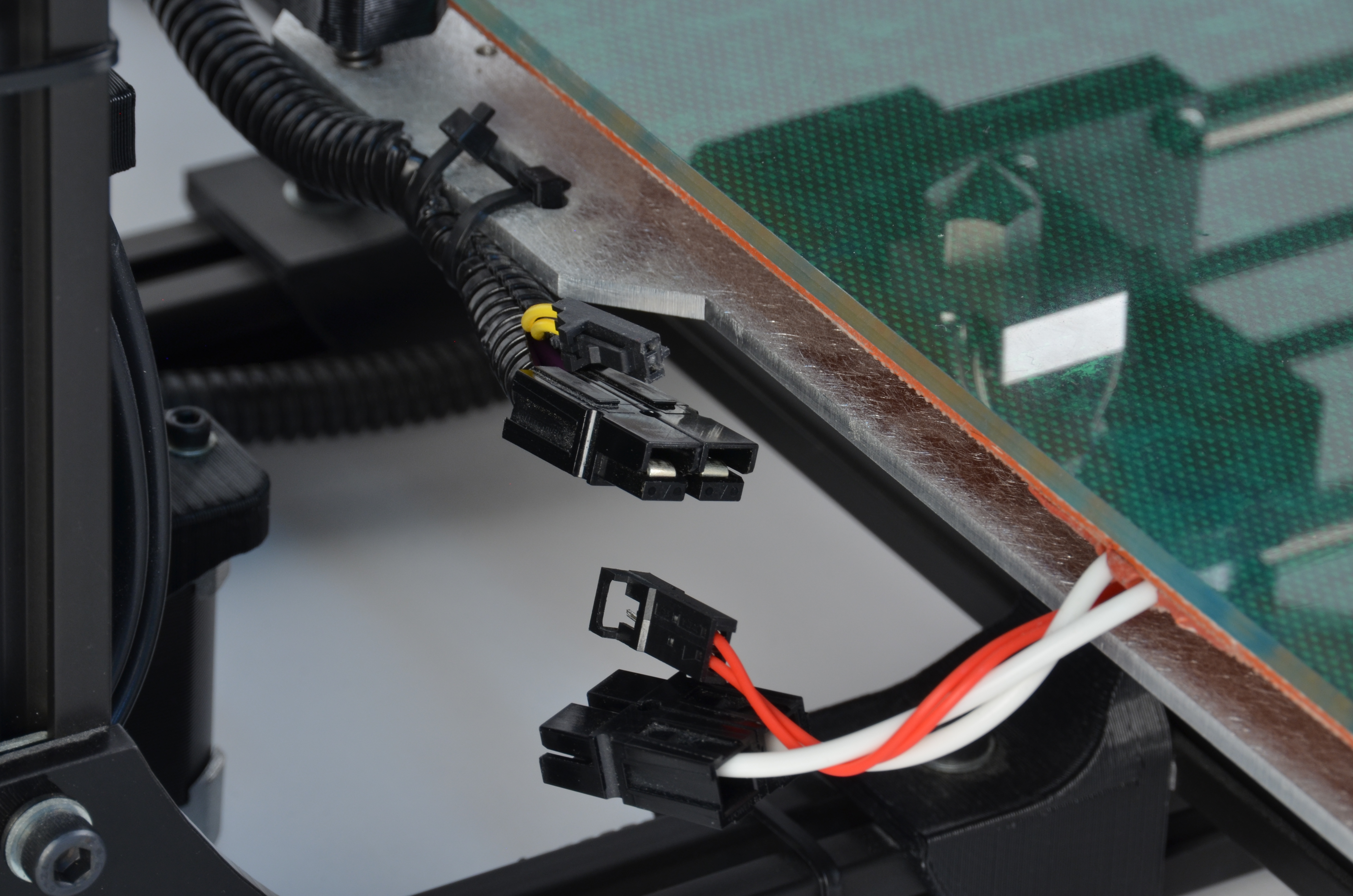
The fan connector will need to be plugged into the connection labeled Fan2. If the fan is already plugged in at this location and working continue to the next step. If the fan is plugged into the connection labeled X30 continue with the instructions below.
Using the Dental Pick from the TAZ toolkit, remove the pins from the fan connector by pushing down on each tab on the black connector while pulling on each wire. Once removed, lift the locking tab on the connector pin to allow it to lock back in place once reinserted.
The red wire should go in Pin 2 (right), the black wire should be in Pin 1, and may be marked with a triangle on the left side)
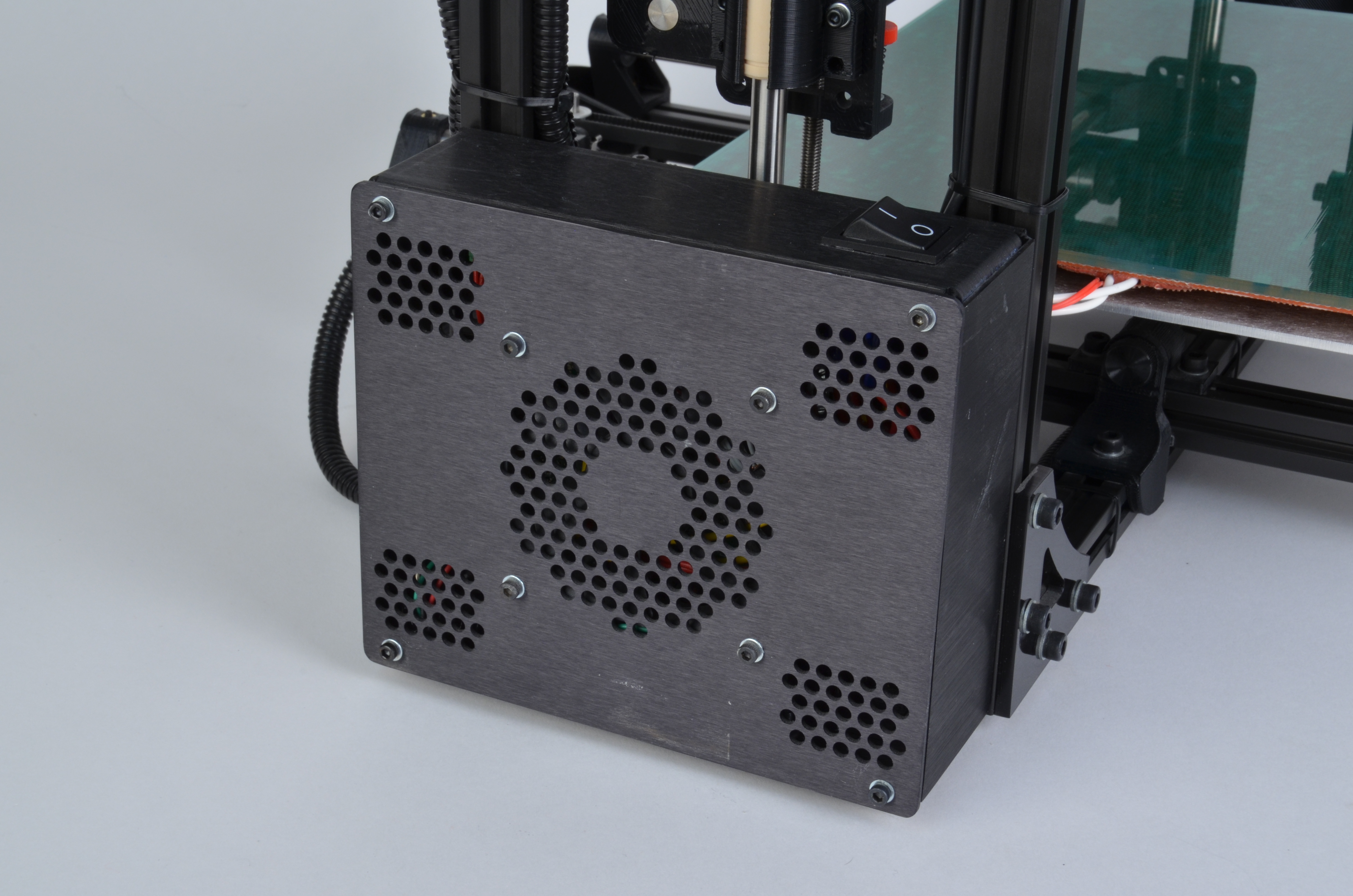
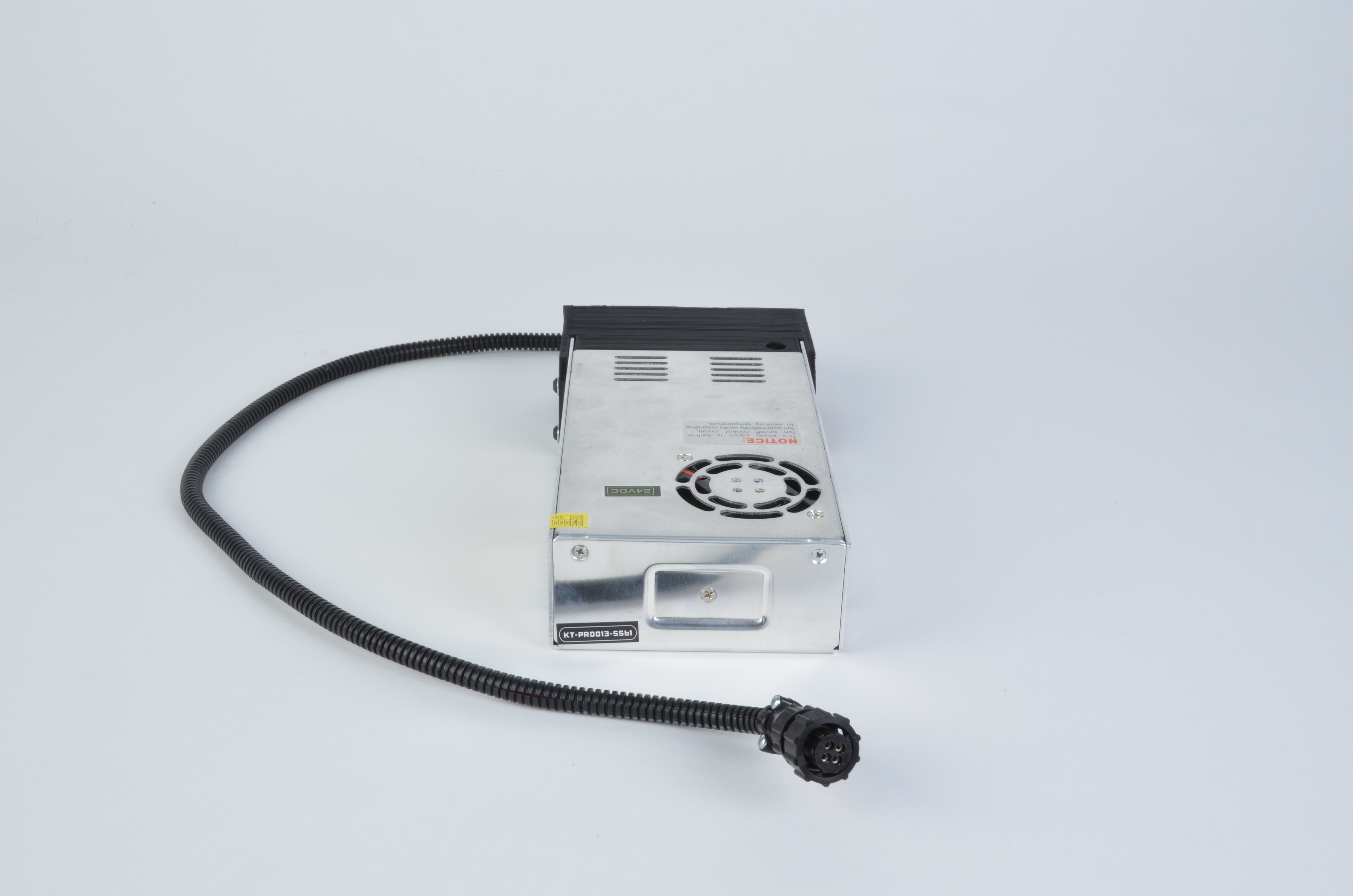
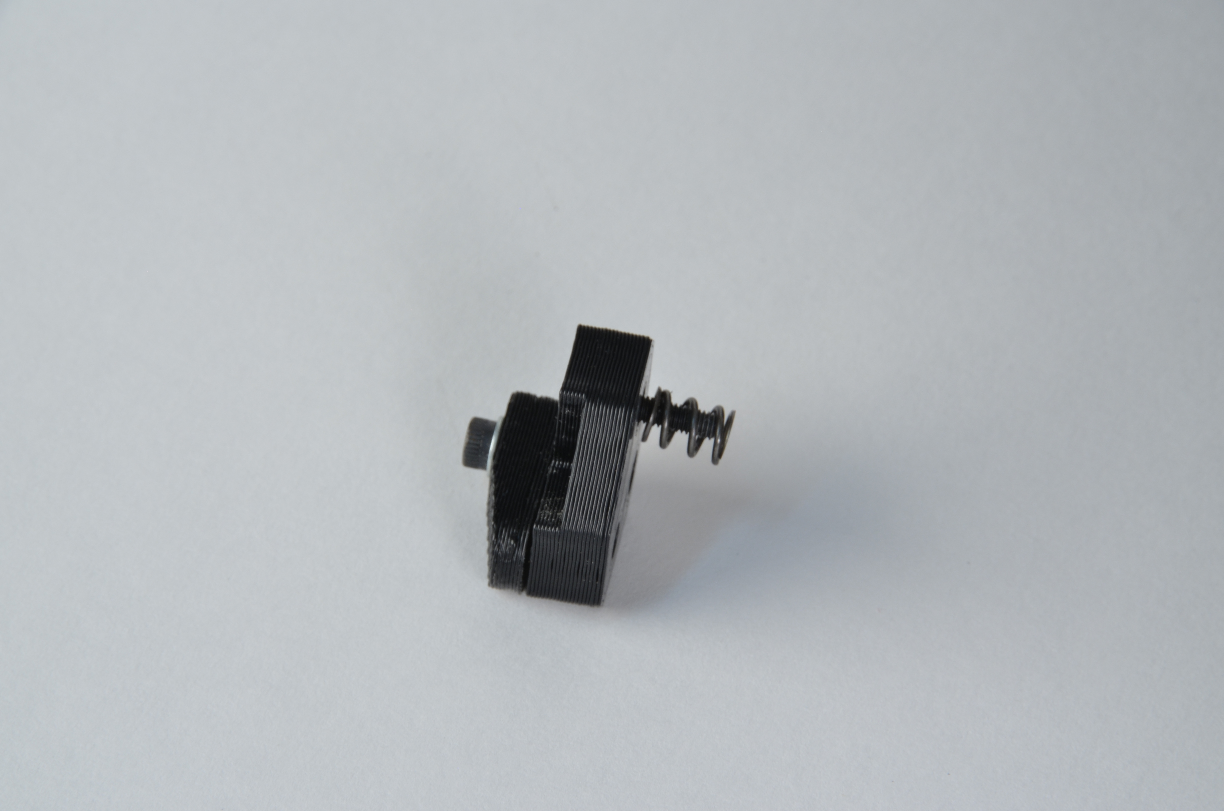
You will need to transfer the existing black printed power supply cover with integrated harness from the 12V power supply to the new 24V power supply.

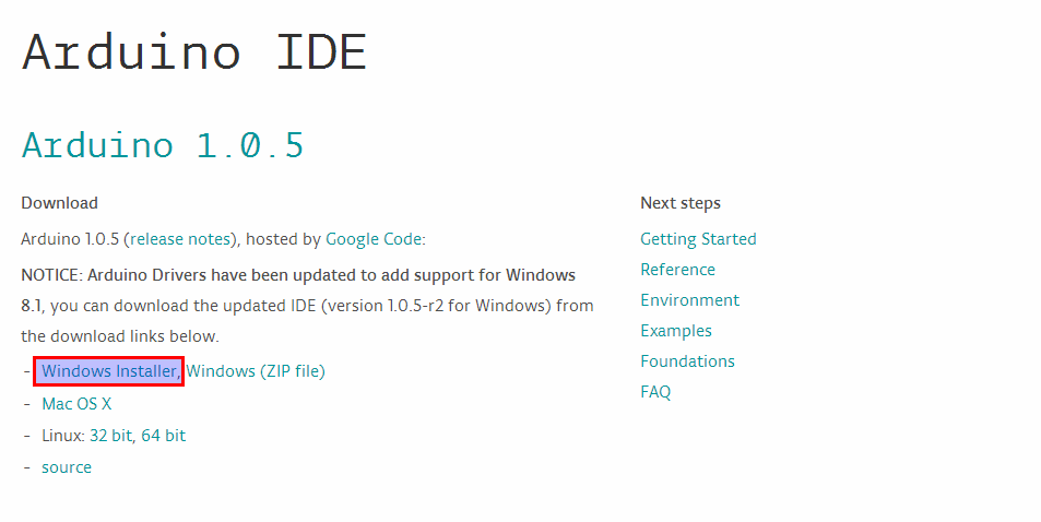
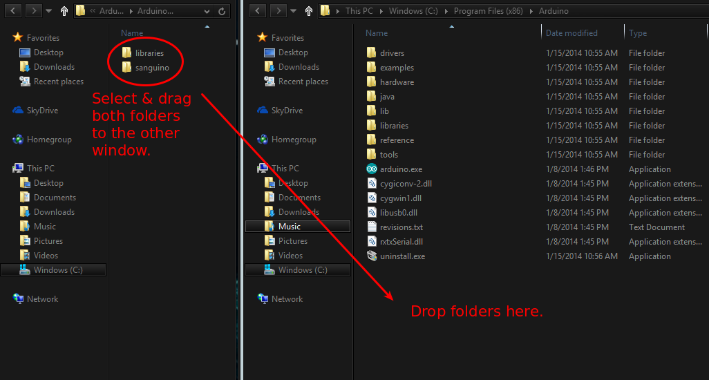
Download the Arduino IDE, version 1.0.5 or higher: Arduino.cc
Install the Arduino IDE

If you are unsure how to continue, contact LulzBot Technical Support by sending an email to: Support@LulzBot.com.
Continue if the sketch compiles with no errors and displays Done compiling. If the compiling fails, stop and contact Support@LulzBot.com for assistance.
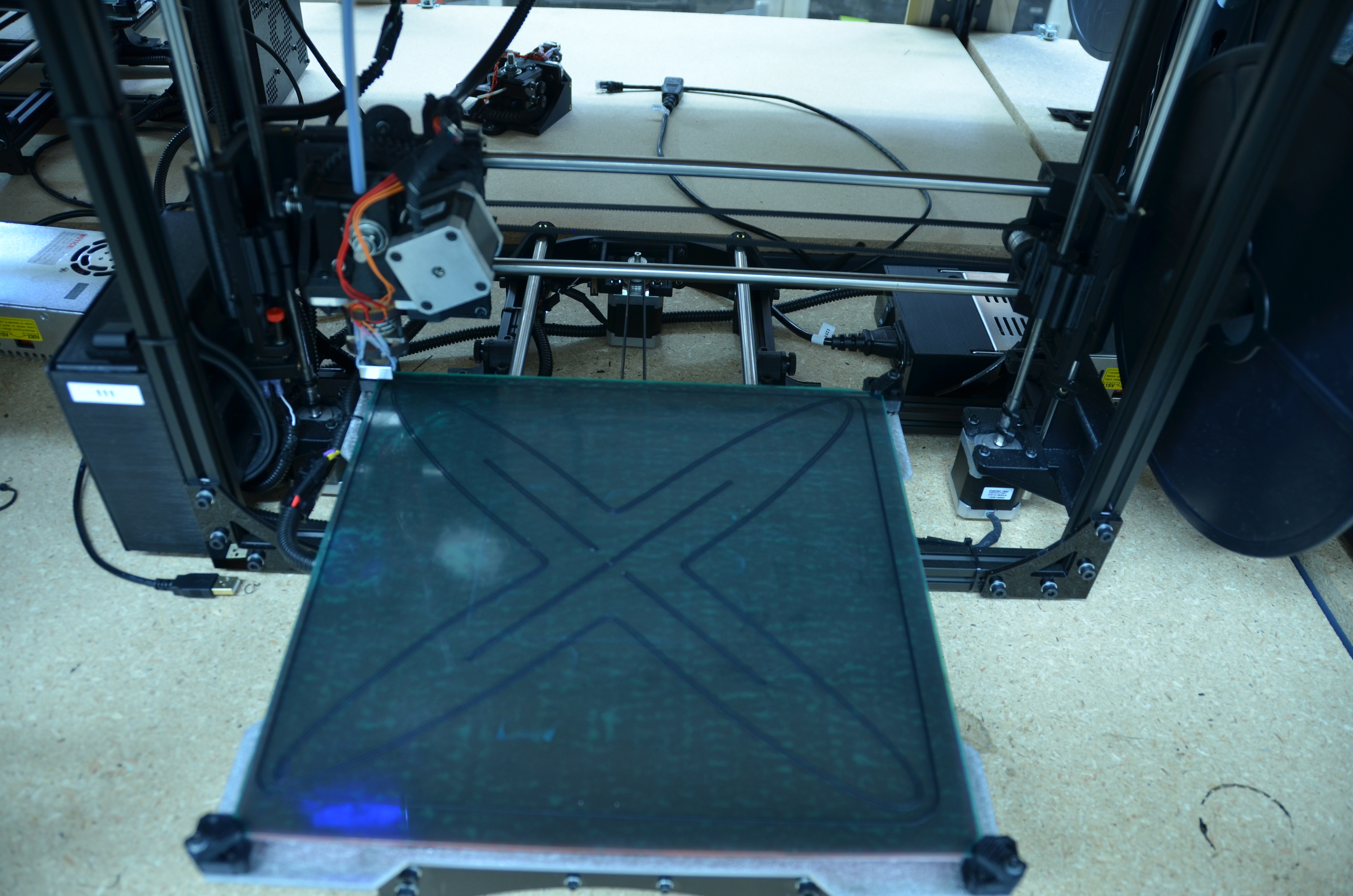
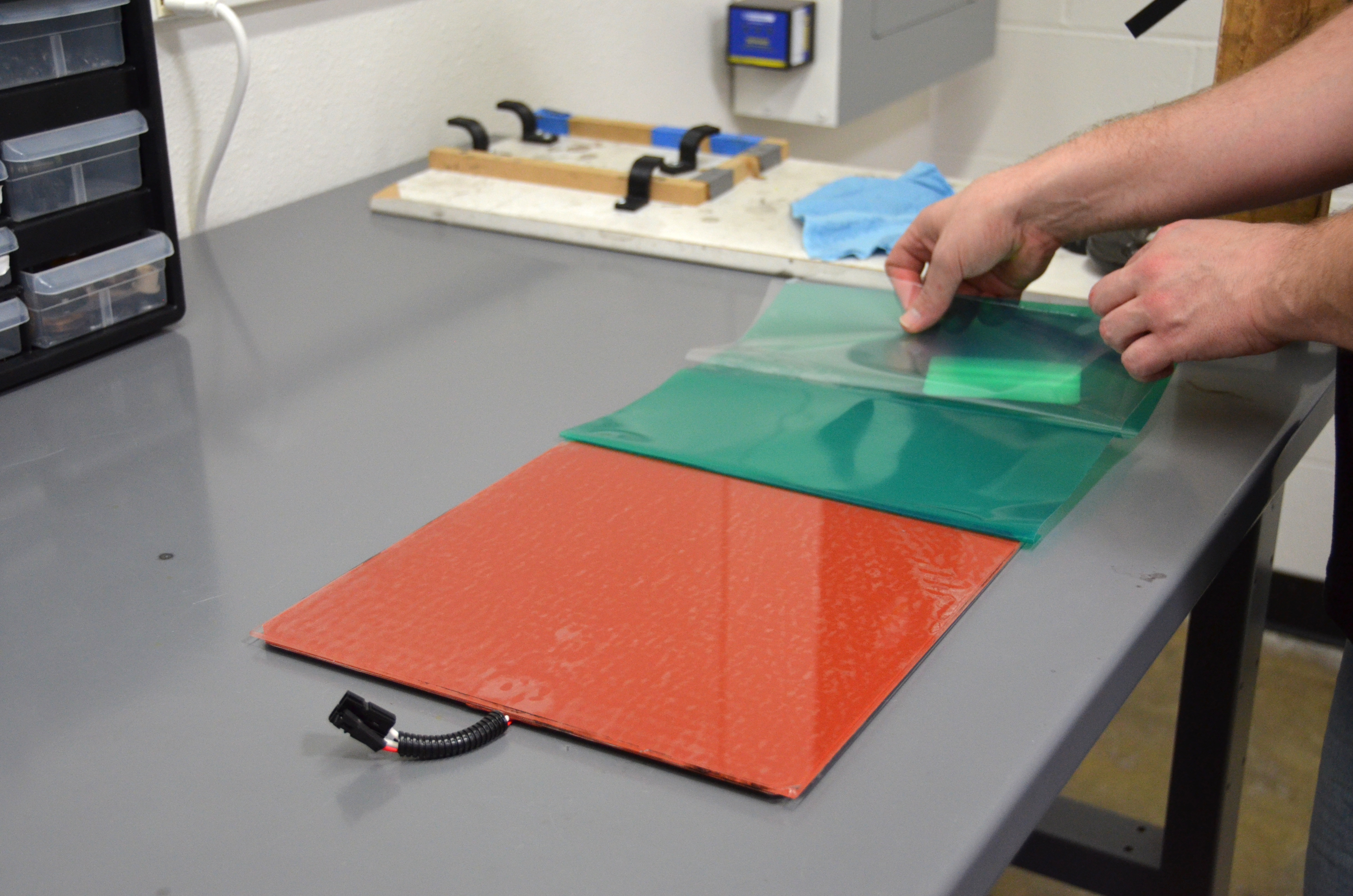
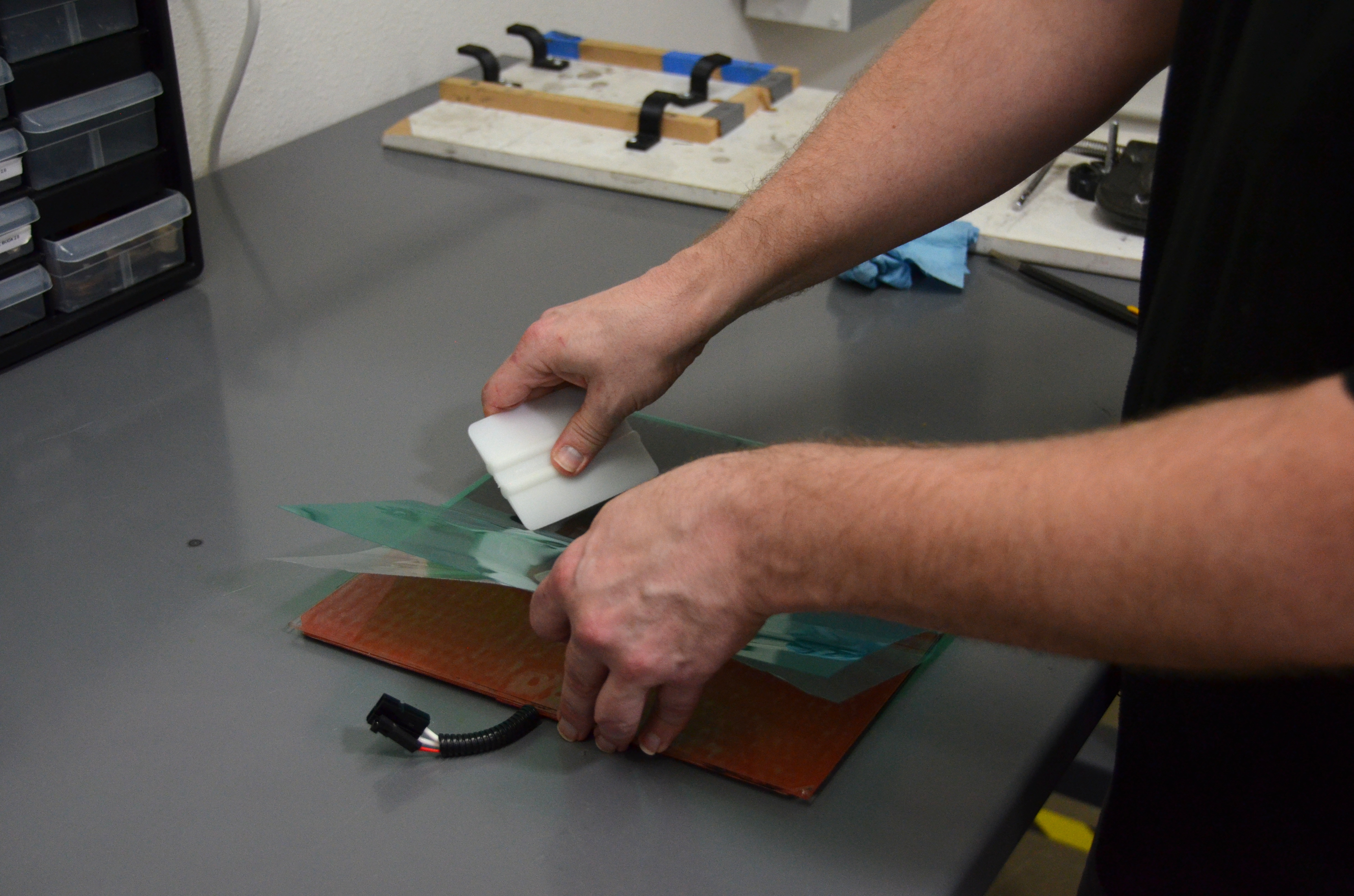
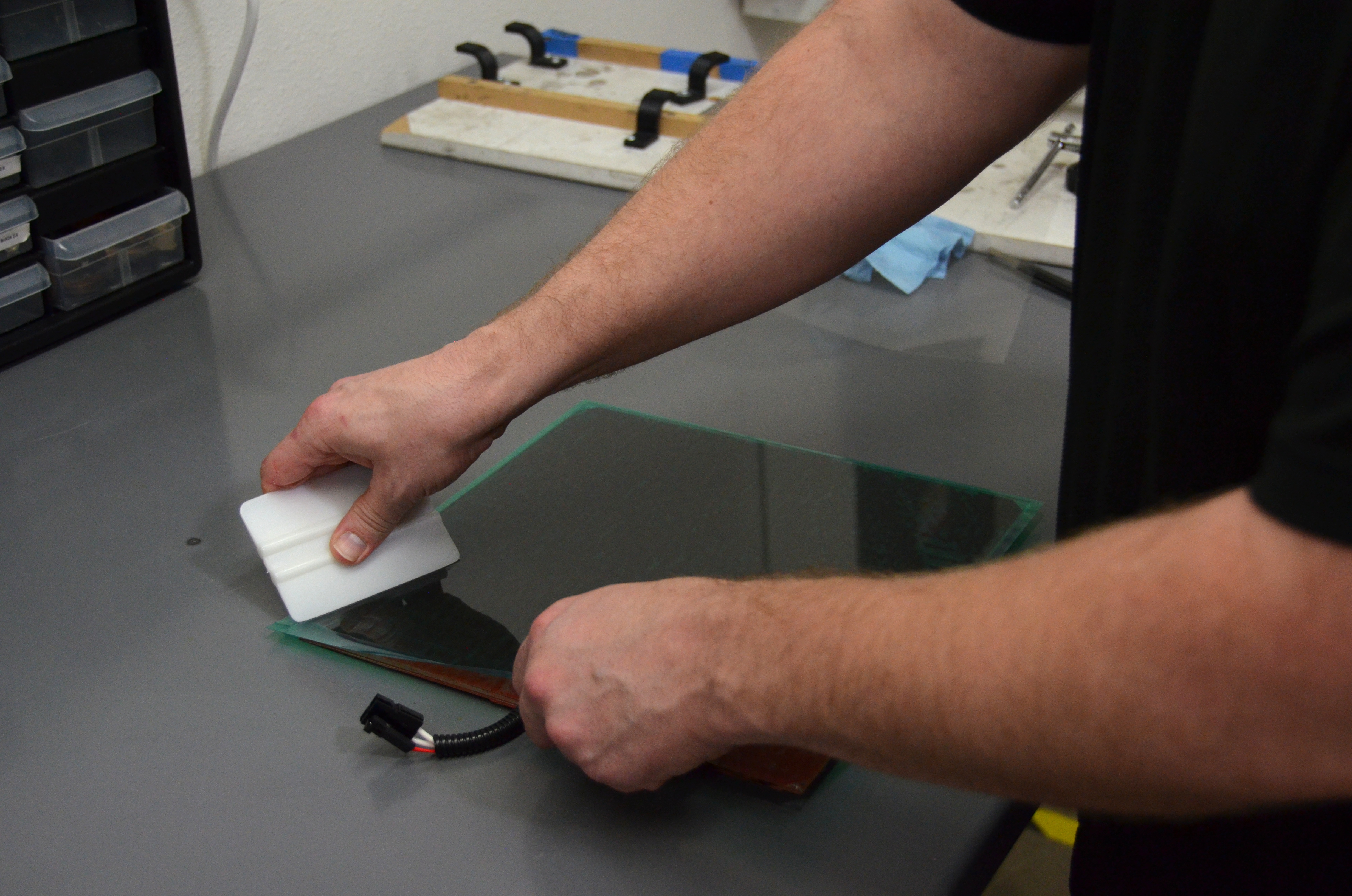
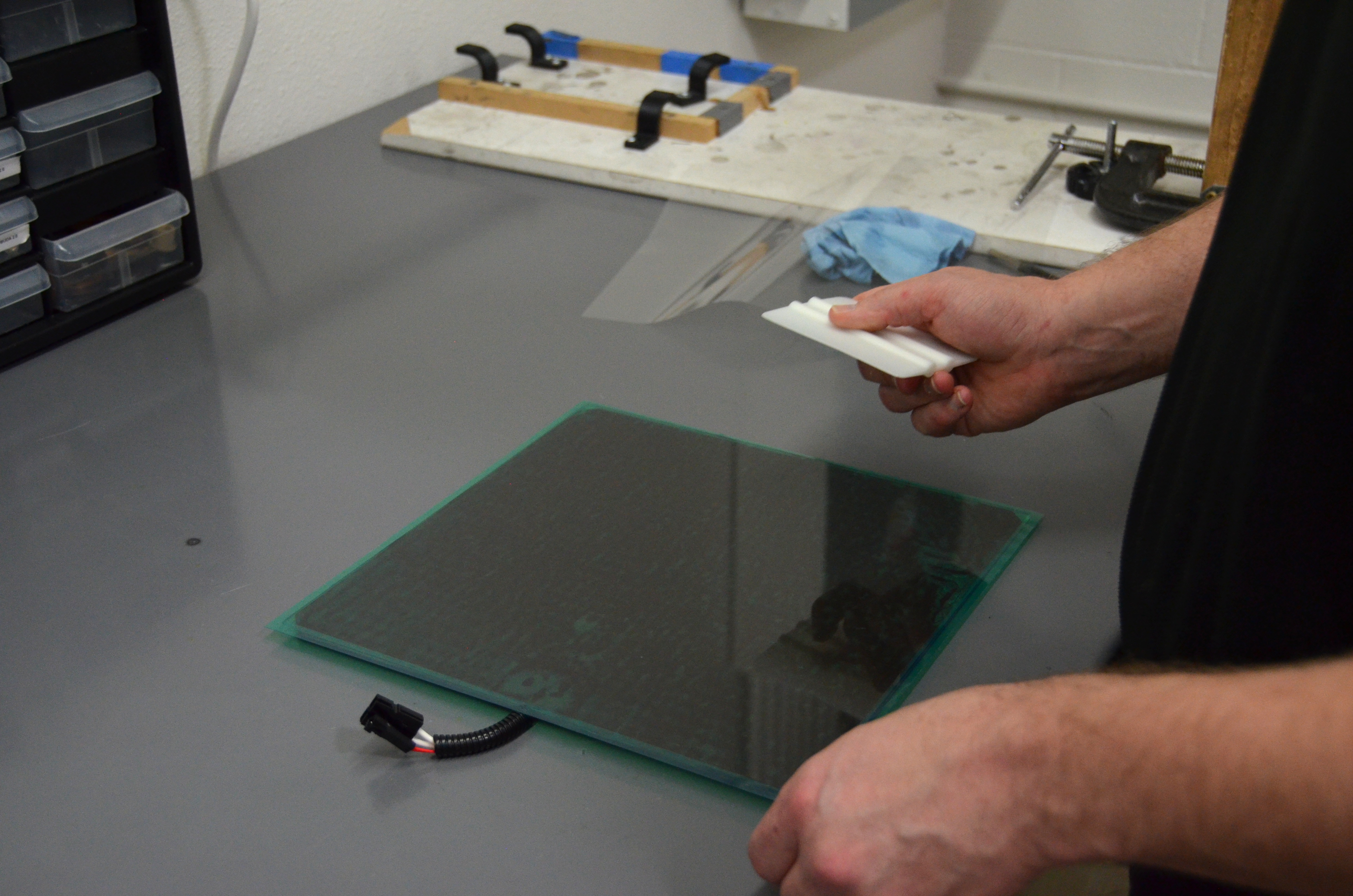
To assemble the 24V bed:
With the assembled 24V bed:

Follow the instructions found in the User Manual in Section 4.1 (page 48).
Once leveled, print your favorite object to test your new 24V TAZ 3D printer!