Open HardwareAssembly Instructions
Guides for installation and assembly of the LulzBot line of products made by FAME 3D LLC.
Guides for installation and assembly of the LulzBot line of products made by FAME 3D LLC.
Please note:
If you have purchased a LulzBot TAZ 5 v2c Tool Head Harness please skip steps 5 thru 7.
Also, the current version of the LulzBot TAZ Single Extruder Tool Head v2 and the harness you purchased, utilize a single 16 position connector housing for the extruder, rather than the multiple connectors described in step 13.
Once the harness and tool head are installed, simply align the key pins of the harness with the empty positions on the extruder's connector housing.
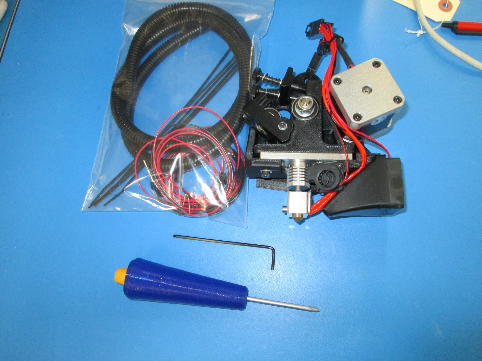
To complete this installation you will need the following 3 items from the Lulzbot Store:
LulzBot TAZ 5 v2c Tool Head Harness
LulzBot TAZ Single Extruder Tool Head v2
Internal Blower Harness Add-on
You will also need the following tools:
-2.5mm hex tool
-Phillips screw driver
-Scissors/any tool to cut zip ties
-Turn off your TAZ before changing anything for safety and to ensure you don't fry components on your printer.
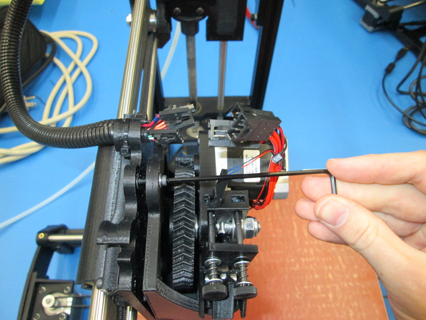
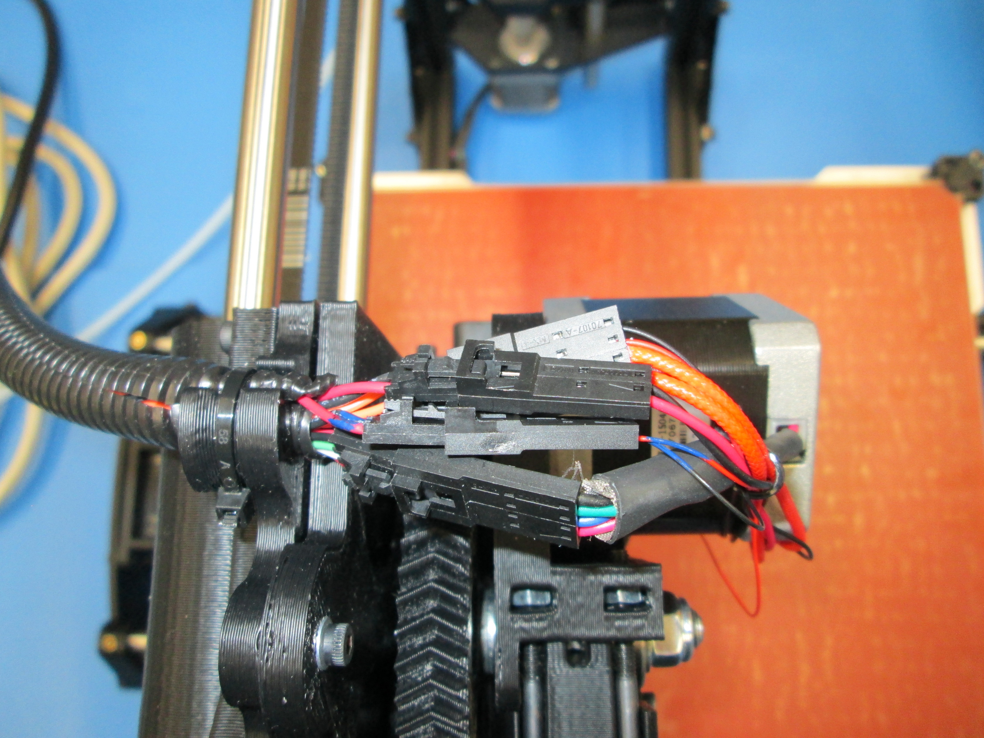
-Unplug the connectors from the current toolhead.
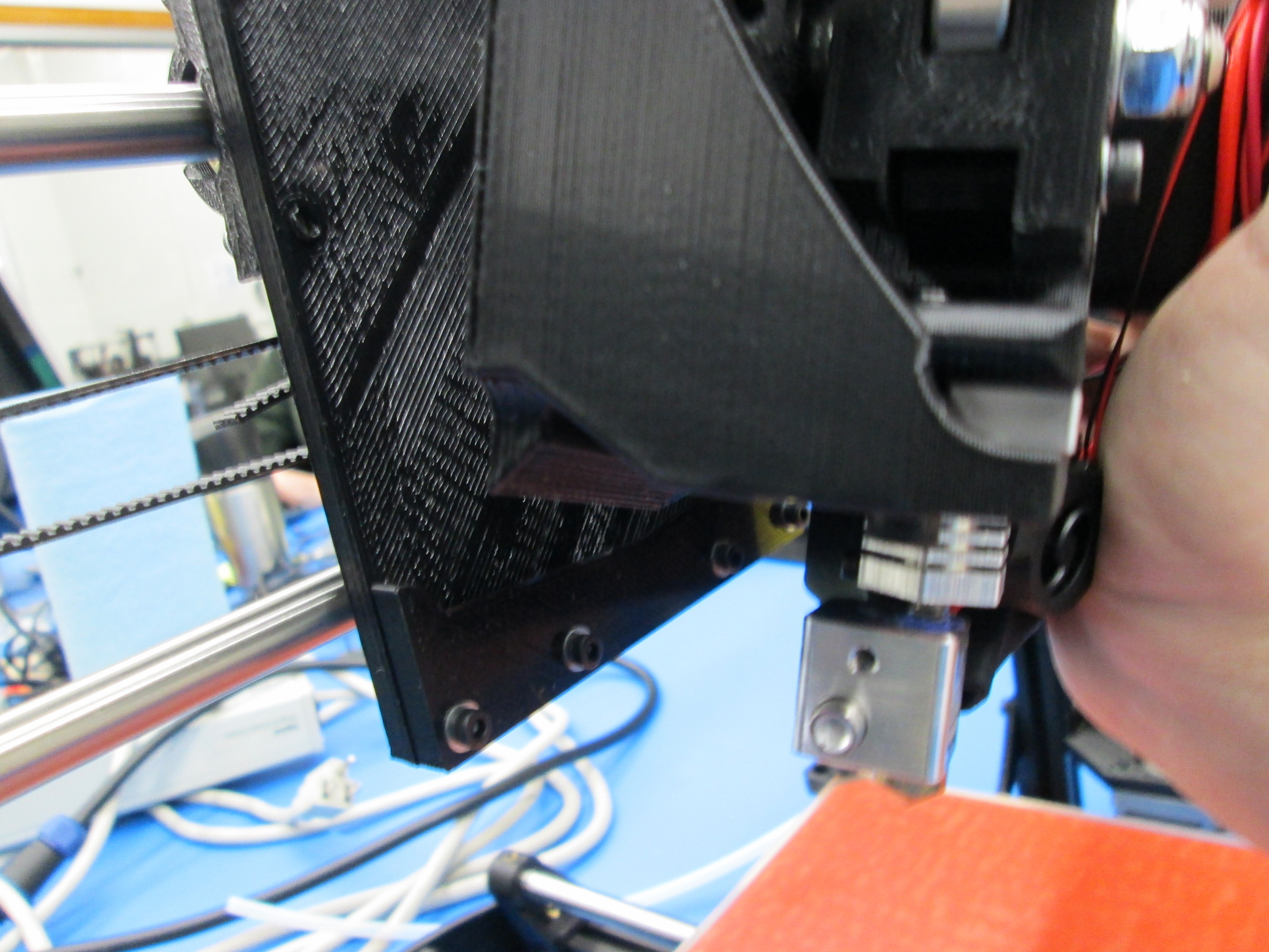
-Using the 2.5mm hex unscrew the the top screw on the tool head.
-Then lift the toolhead off in an upward motion.

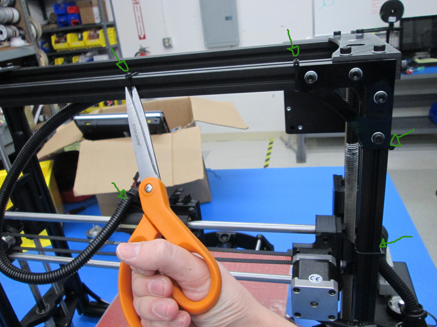
-Remove the zip ties that hold the upper harness on the TAZ frame.
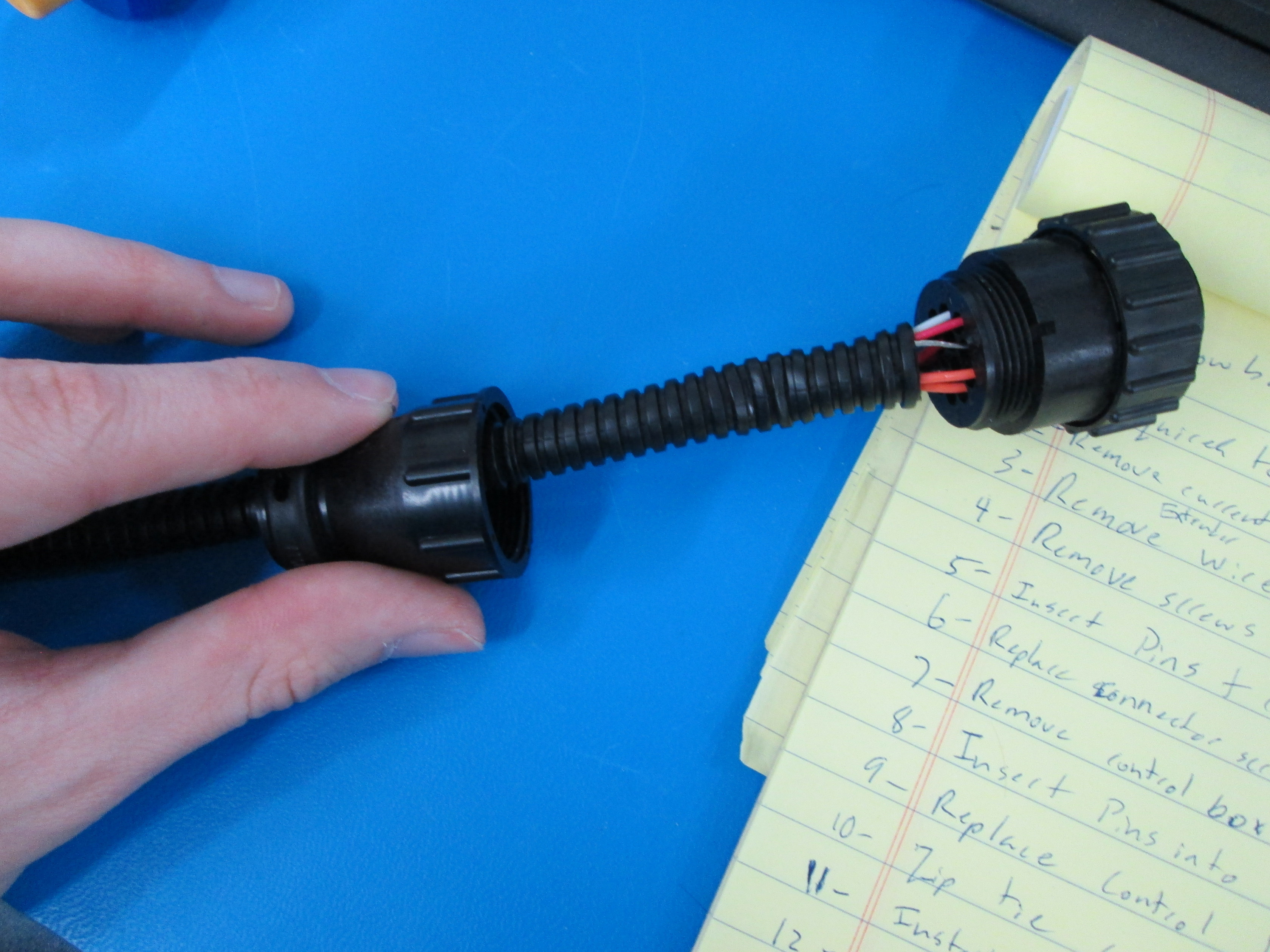
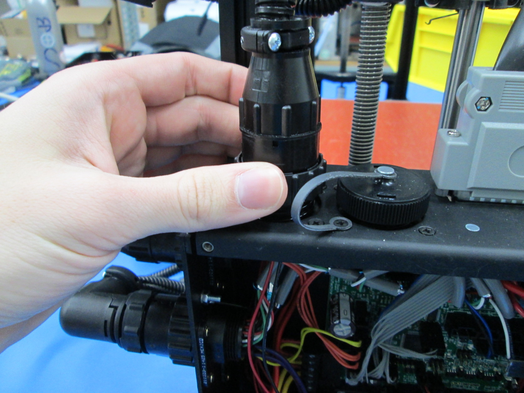
-Unscrew the harness connector from the control box.
-Set harness on table.

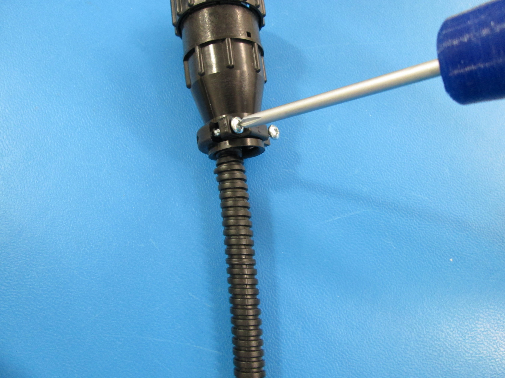
-Using Phillips head, unscrew the the two screws on the harness connector.
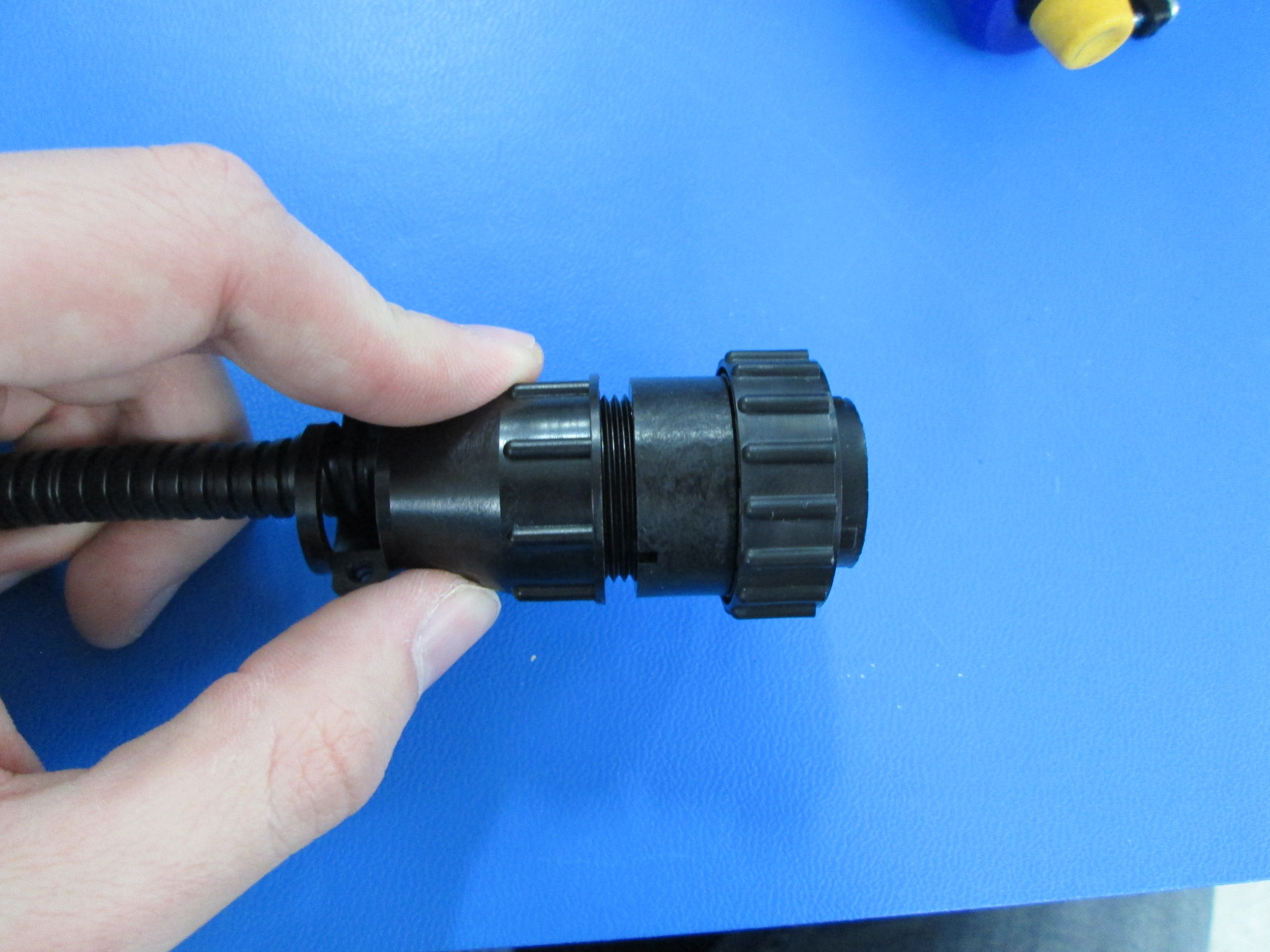
-Unscrew the bottom part of the connector.
-Remove panduit from wires.
-Insert wires with male pins(longer metal ends) though the bottom part of the unscrewed connector.

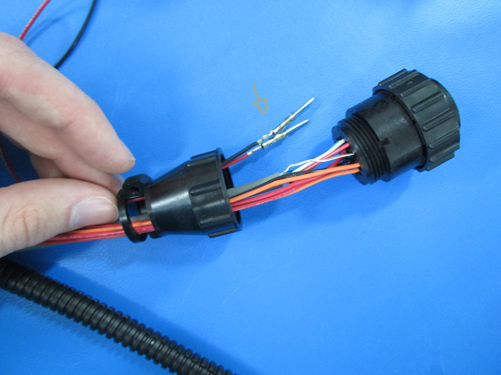
(You may need to spin the pins back in forth until it easily slides in. Needle nose pliers may make this easier for some)
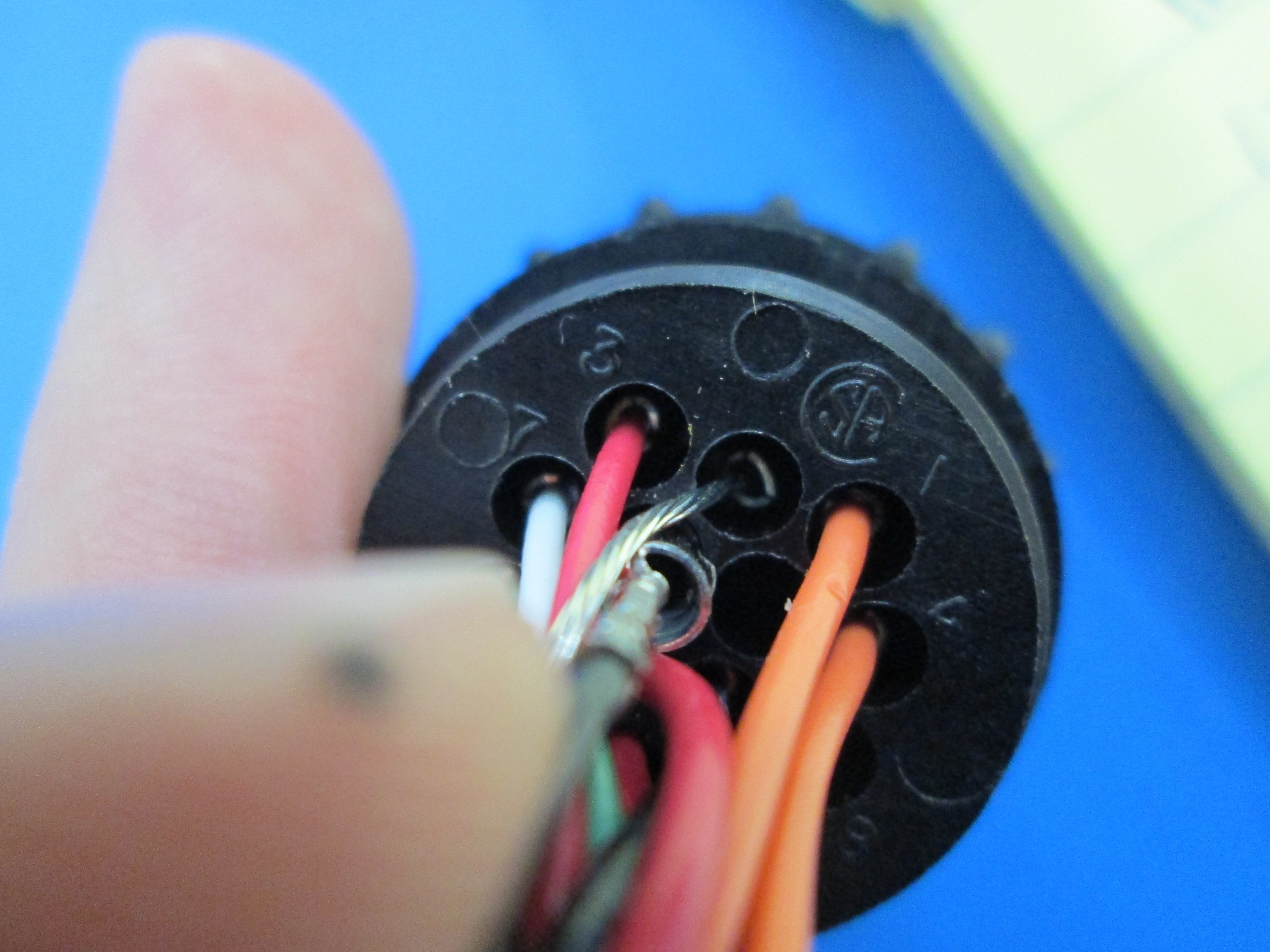
-Take the red male pin and insert it into pin 5 on the connector.
-Take the black male pin and insert it into pin 6 on the connector.
-The pin should make an audible click when they are fully secured to the connector.

-Insert the wires into the new panduit that came with your fangtooth kit.
-Pull panduit through bottom part of connector.
-Screw bottom part of connector back to top part of connector.
-Using the phillips head screw driver, replace the plastic piece and screw the connector back together.

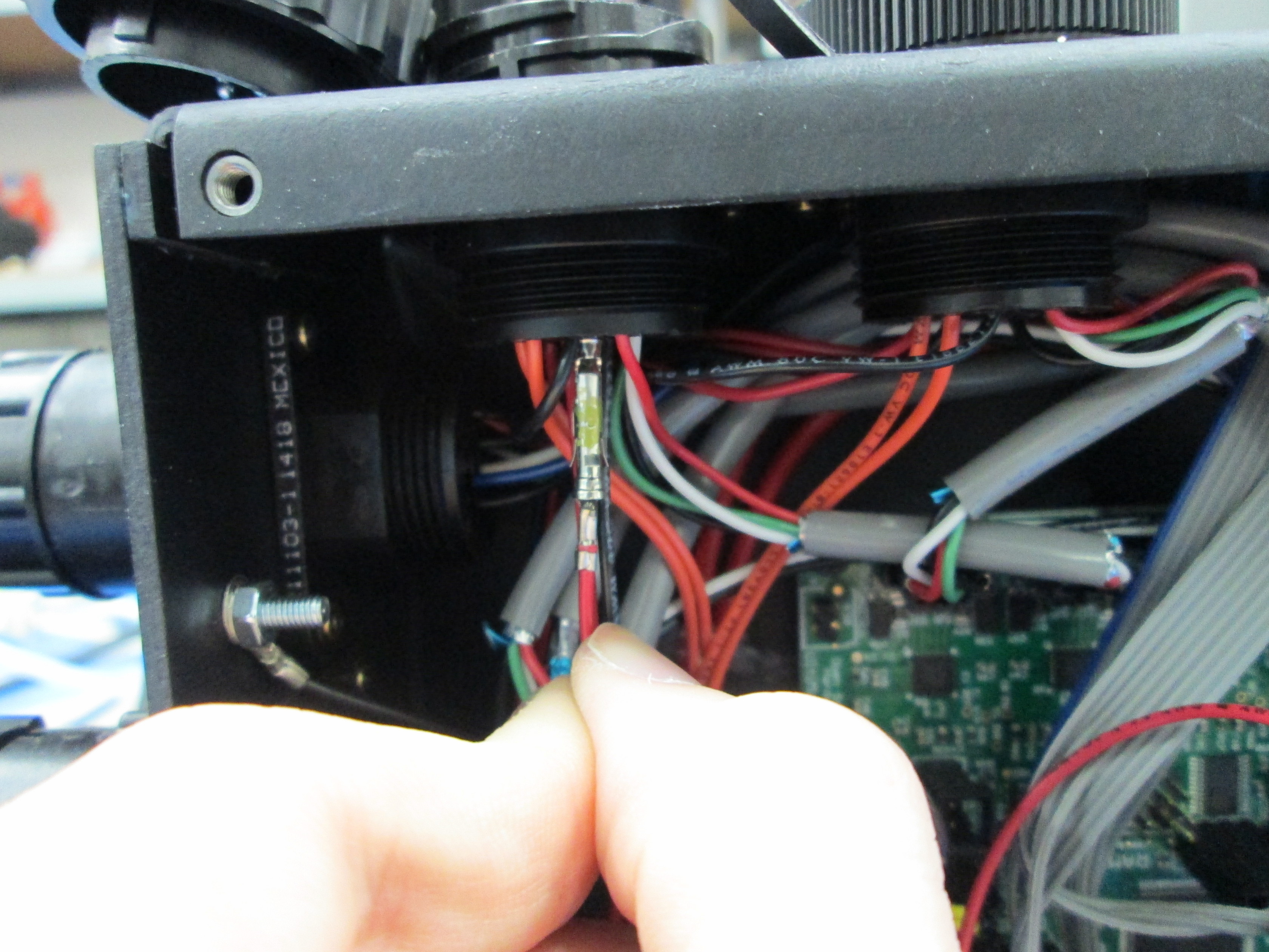
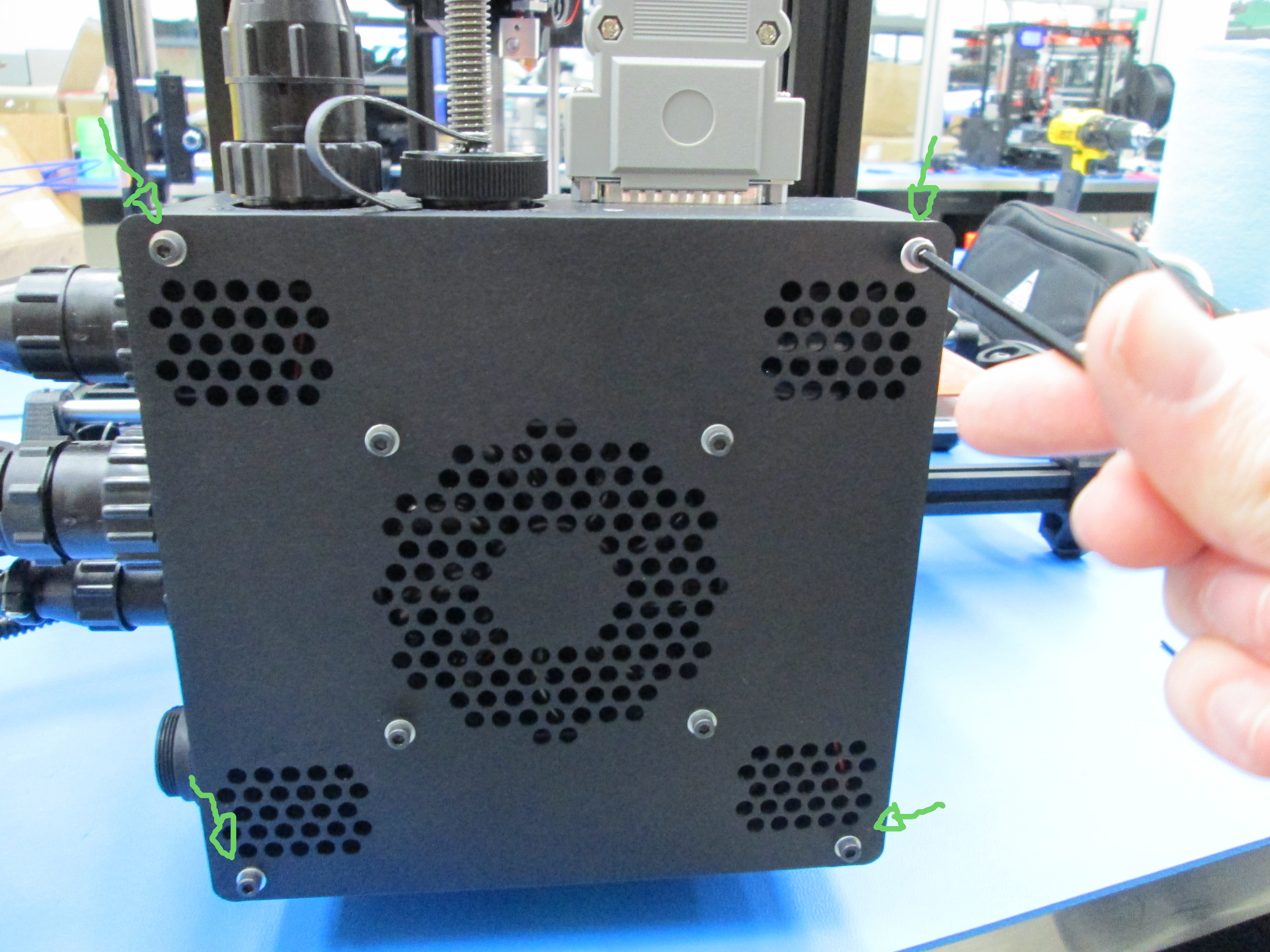
-Using the 2.5mm hex tool, remove the 4 screws on the cover of the control box(When the cover comes off be careful of the case fan wires still connected from the cover to the circuit board).

-Remove the shortest wires from your fangtooth kit.
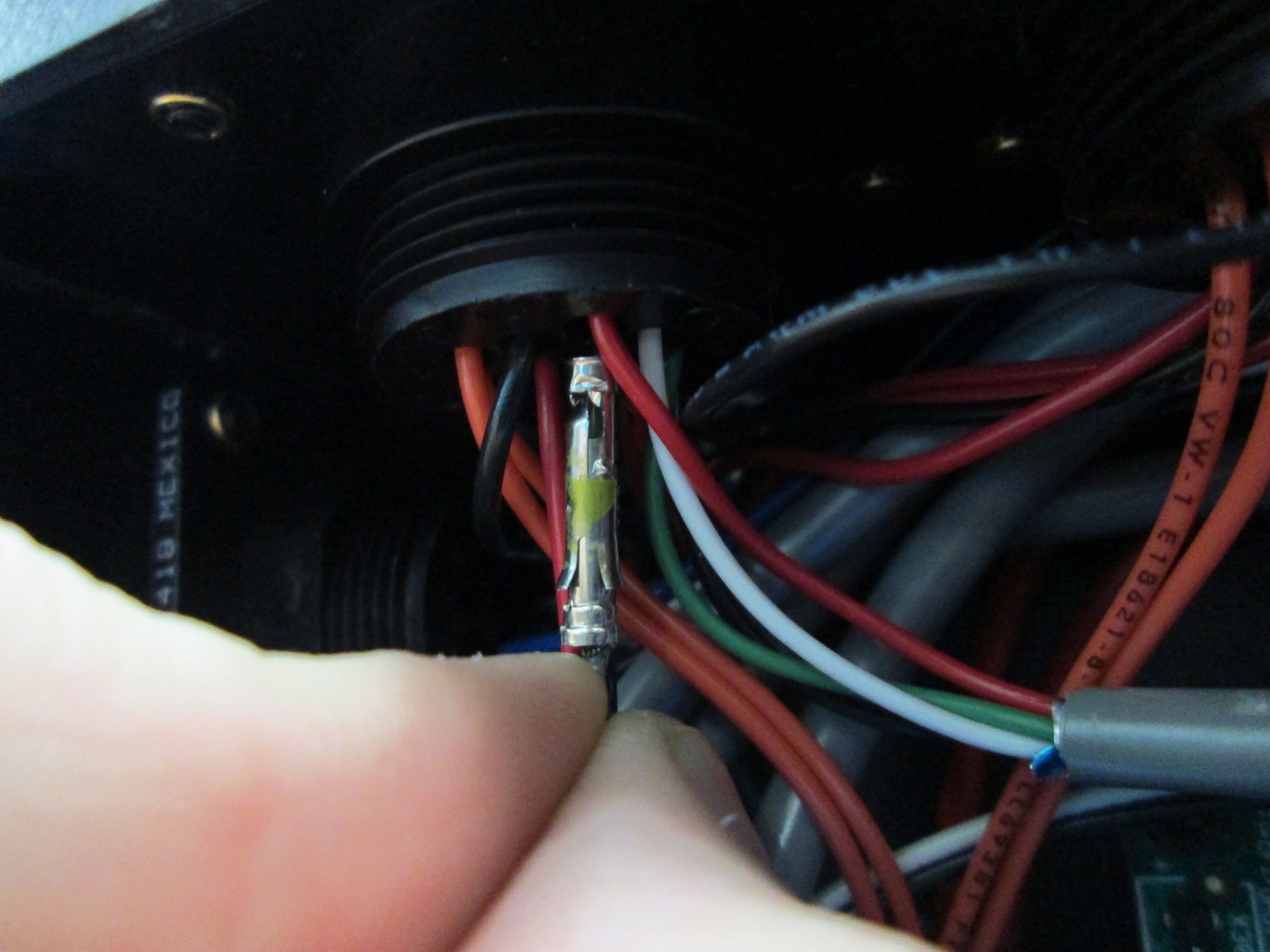
-When plugging the pin into the connector you may need to spin the pins before they slide in all the way.
-Take the red female pin and plug it into pin 5 of the upper harness connector(left open pin on this connector).
-Take the black female pin and plug it into pin 6 of the upper harness connector(right open pin on this connector).
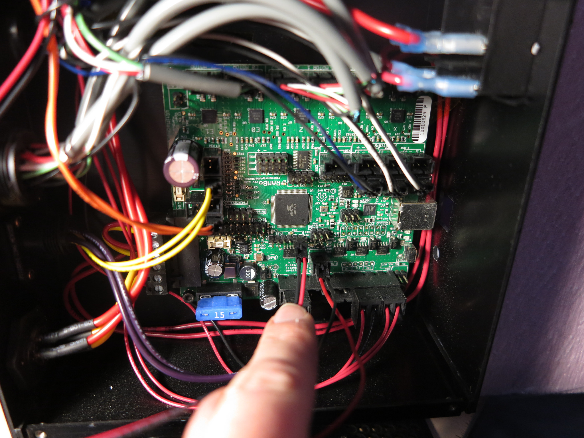
-Take the other side of the short wires and plug connector into the RAMBo as shown.
-The latch on the connector should be facing upwards.
-Using your 2.5mm hex tool replace the 4 screws that hold the control box cover in place.
-Screw your newly created harness back into the the control box.
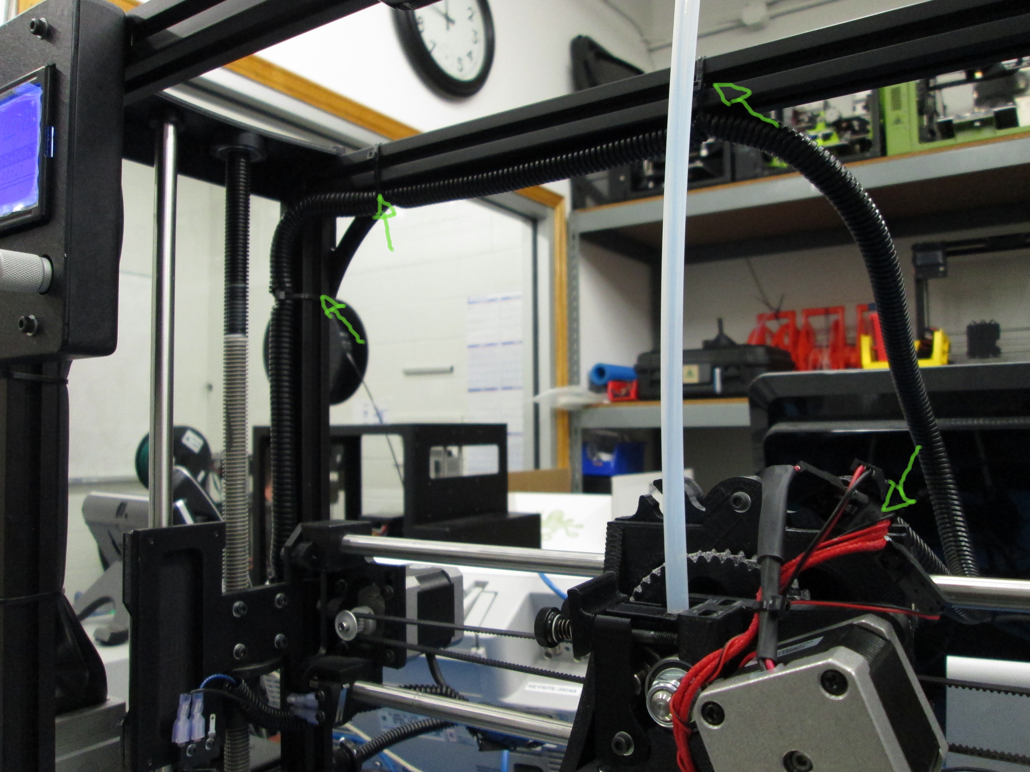
-Zip tie the harness back onto the the TAZ frame at the indicated points(ensure that wire harness is zip tied to the lower part of the top of the frame so that the wire wont interfere with full build volume prints).
-Clip the excess off the zip ties
-Place your new toolhead in the groves in the toolhead mount.
-Using your 2.5mm hex tool screw the toolhead to the mount.
-Plug in the connectors(color coated).
-Connectors with blue paint go together,
-Connectors with red, blue, green, black go together
-Connectors with red and black go together(without blue paint)
-Connector with red, red, red, black and connector with red, red, orange, orange go together.