Open HardwareAssembly Instructions
Guides for installation and assembly of the LulzBot line of products made by FAME 3D LLC.
Guides for installation and assembly of the LulzBot line of products made by FAME 3D LLC.
or

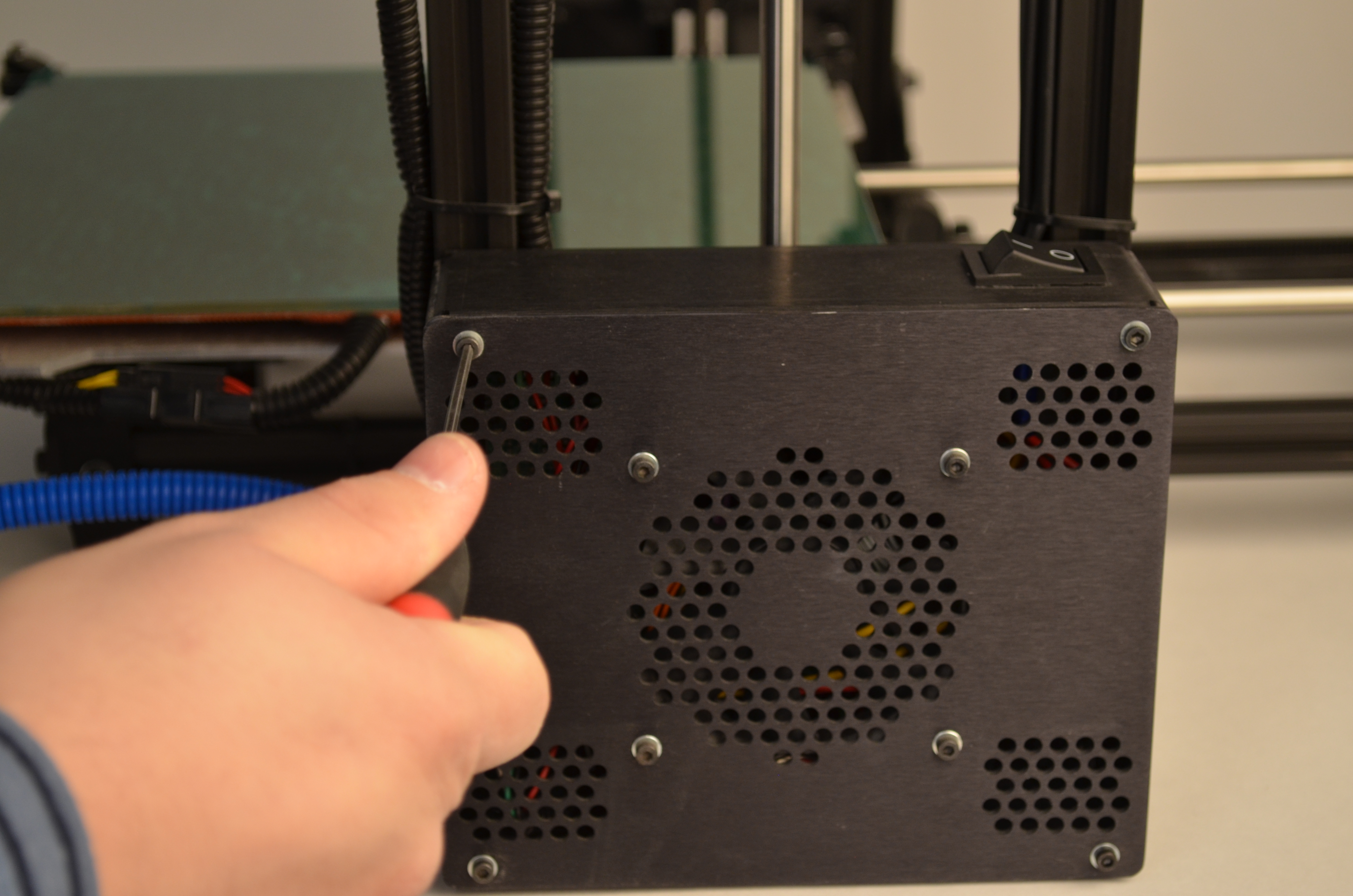
Remove the 4 screws from the outer corners of the electronics enclosure.
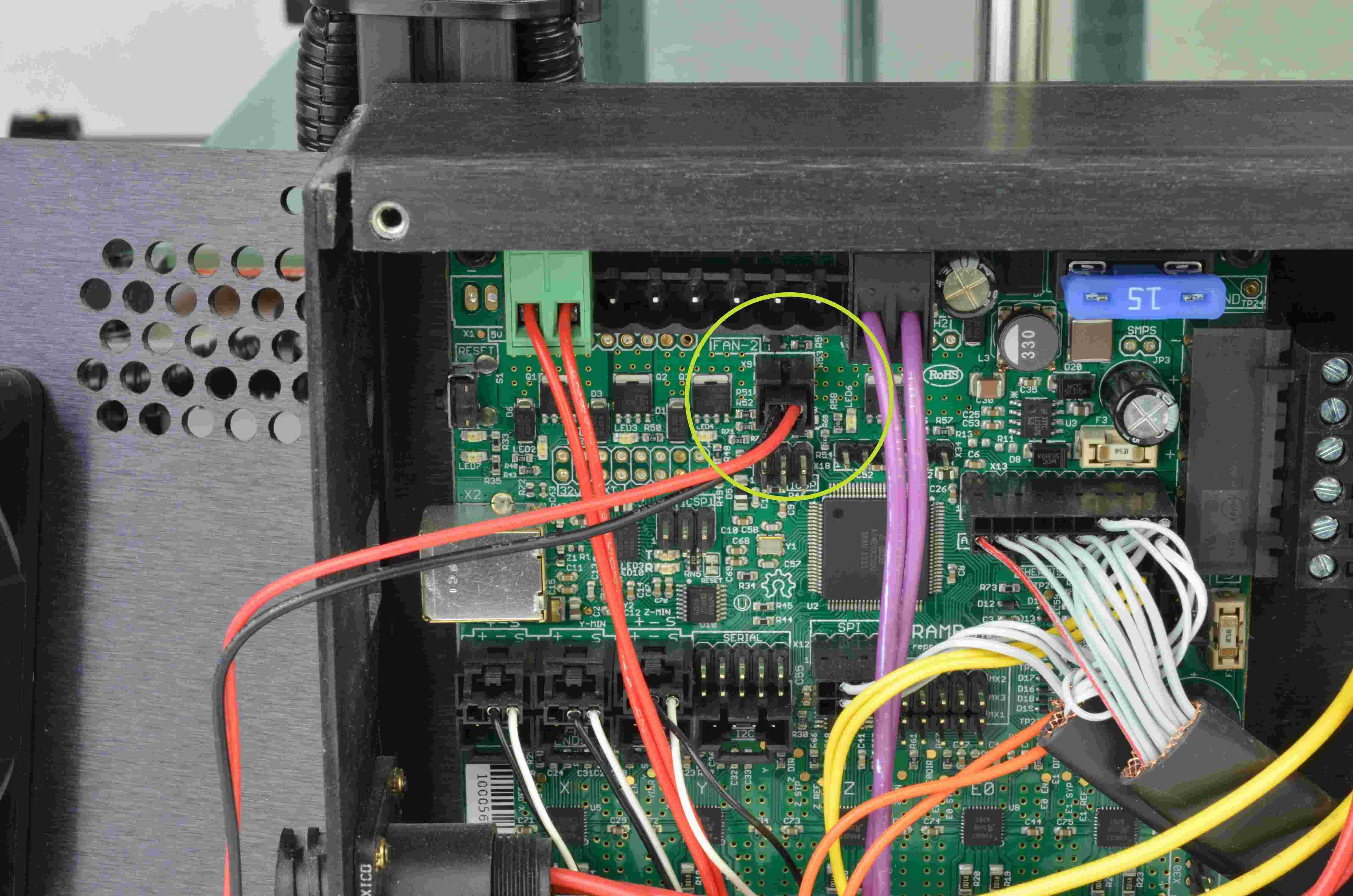
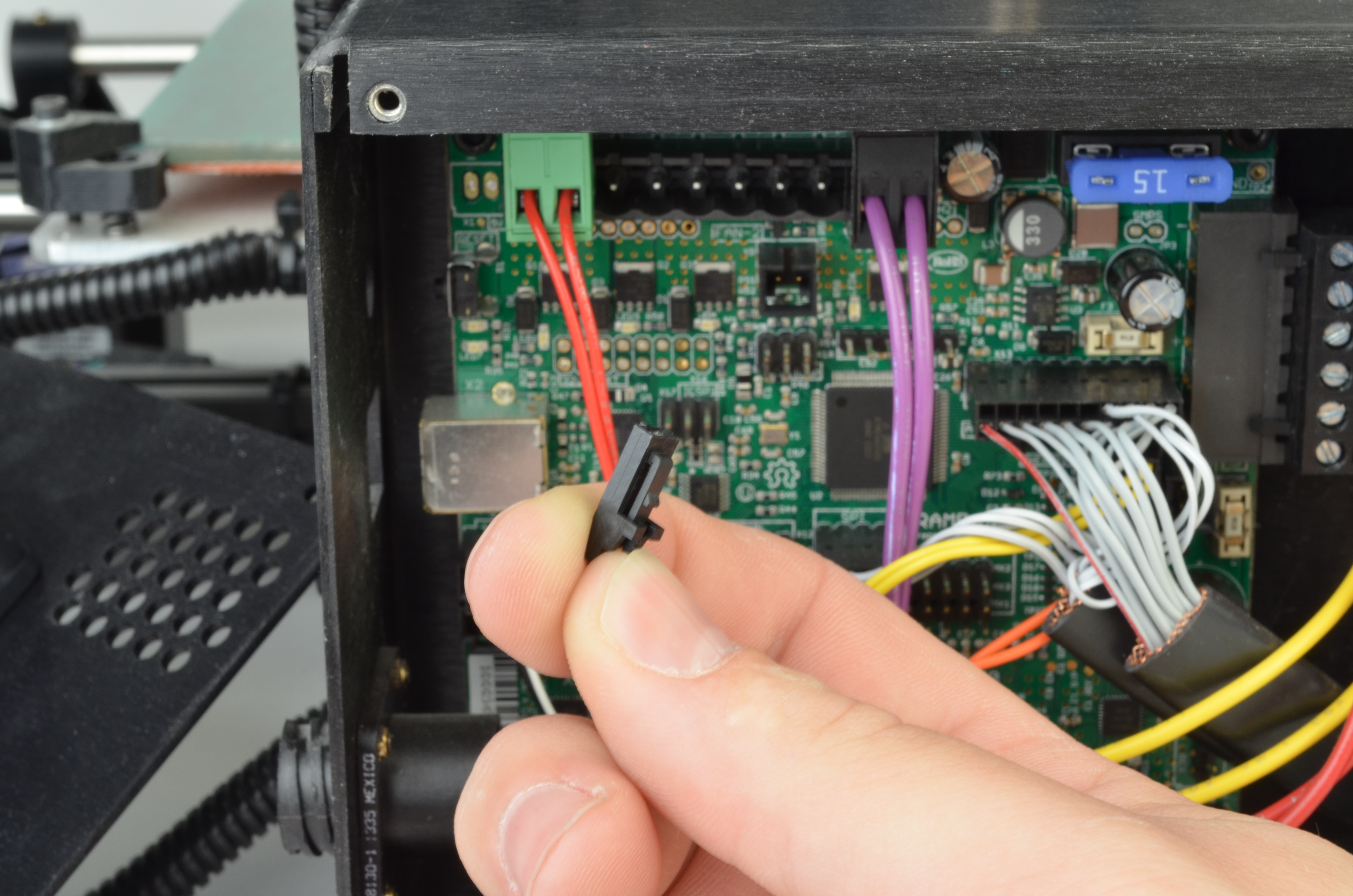
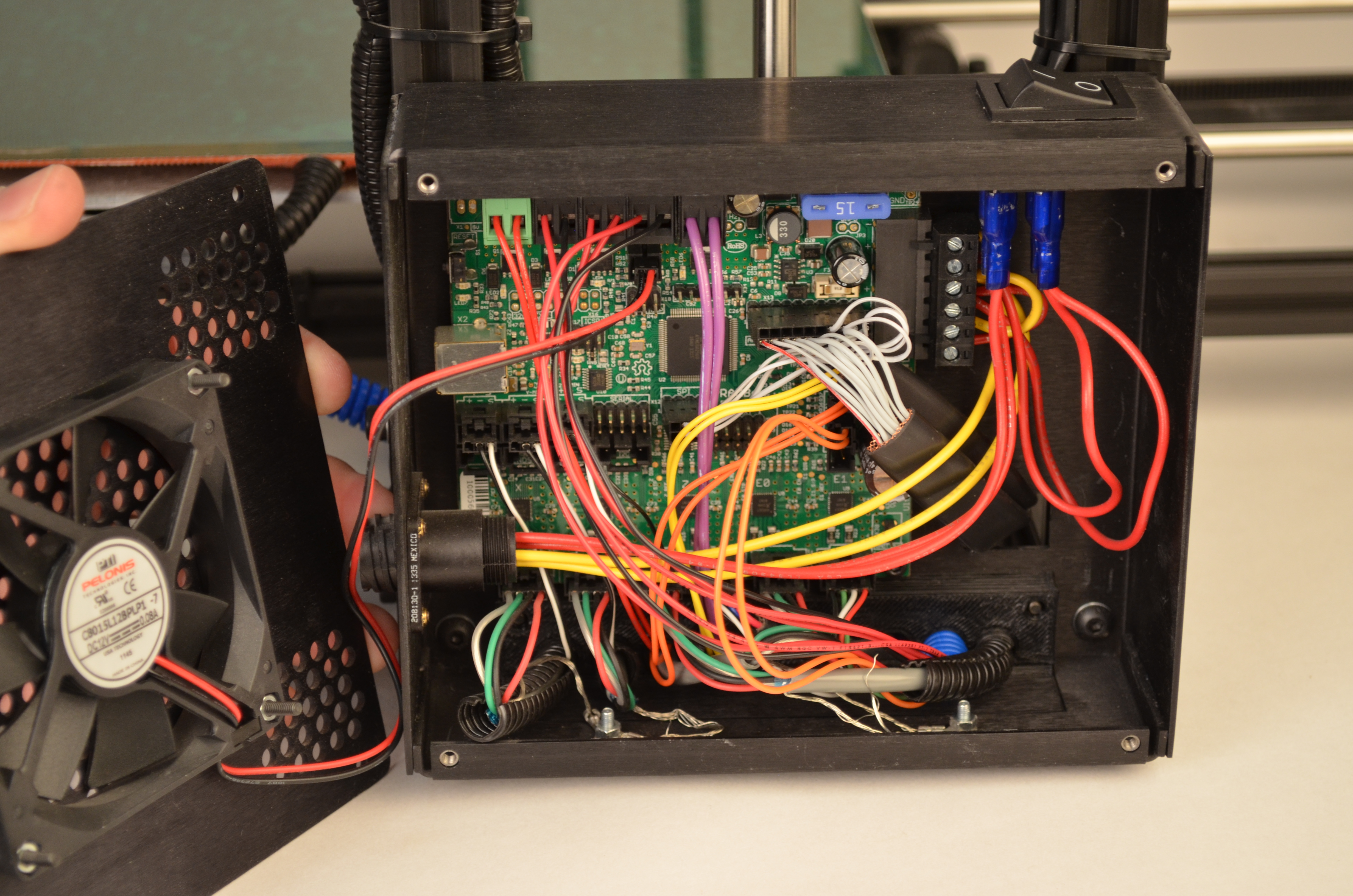
Rotate the electronics enclosure lid out of the way, disconnect the fan wiring and set aside the cover.
Move the TAZ 3D printer so the lower portion of the electronics enclosure is accessible.
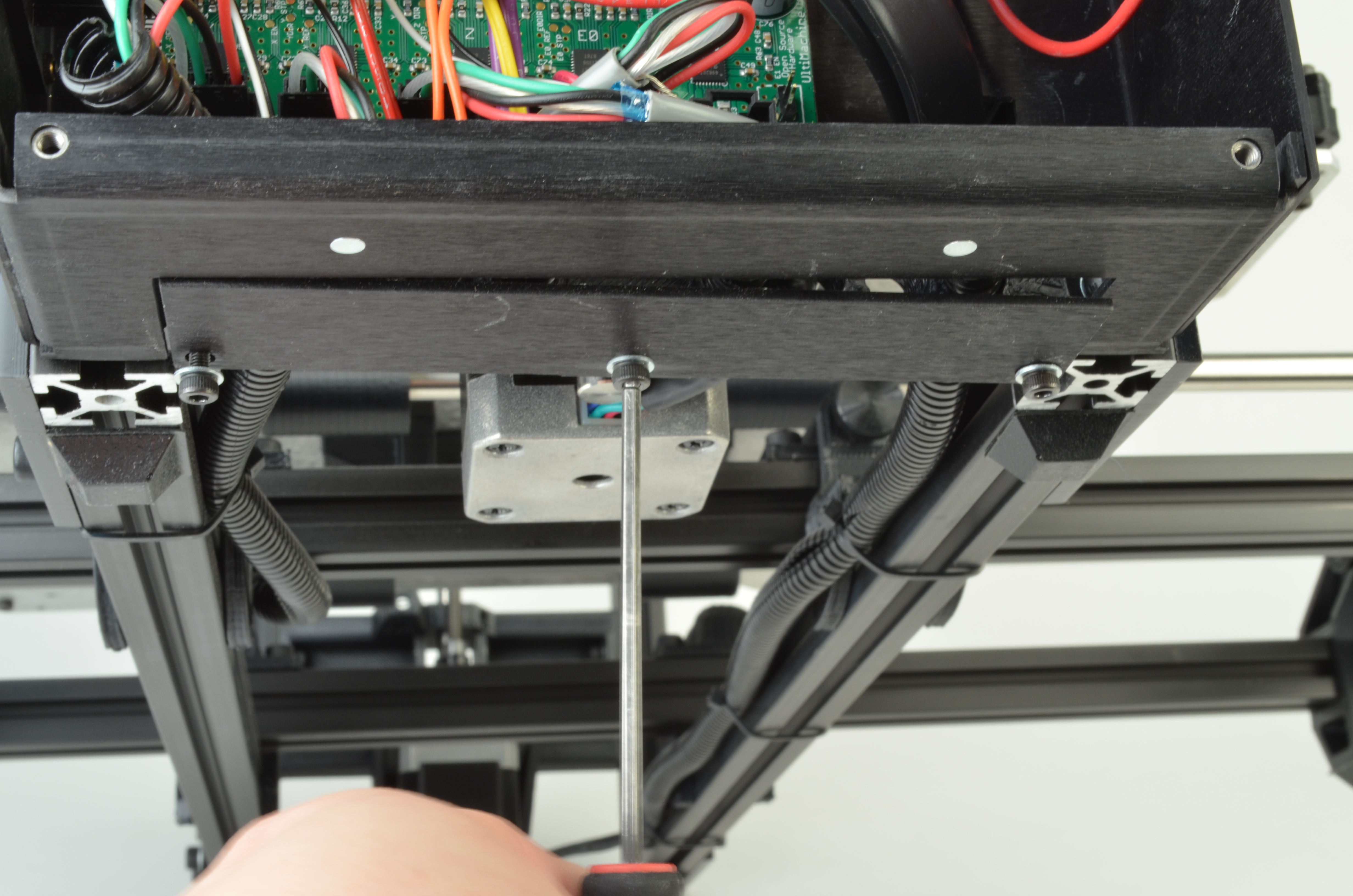
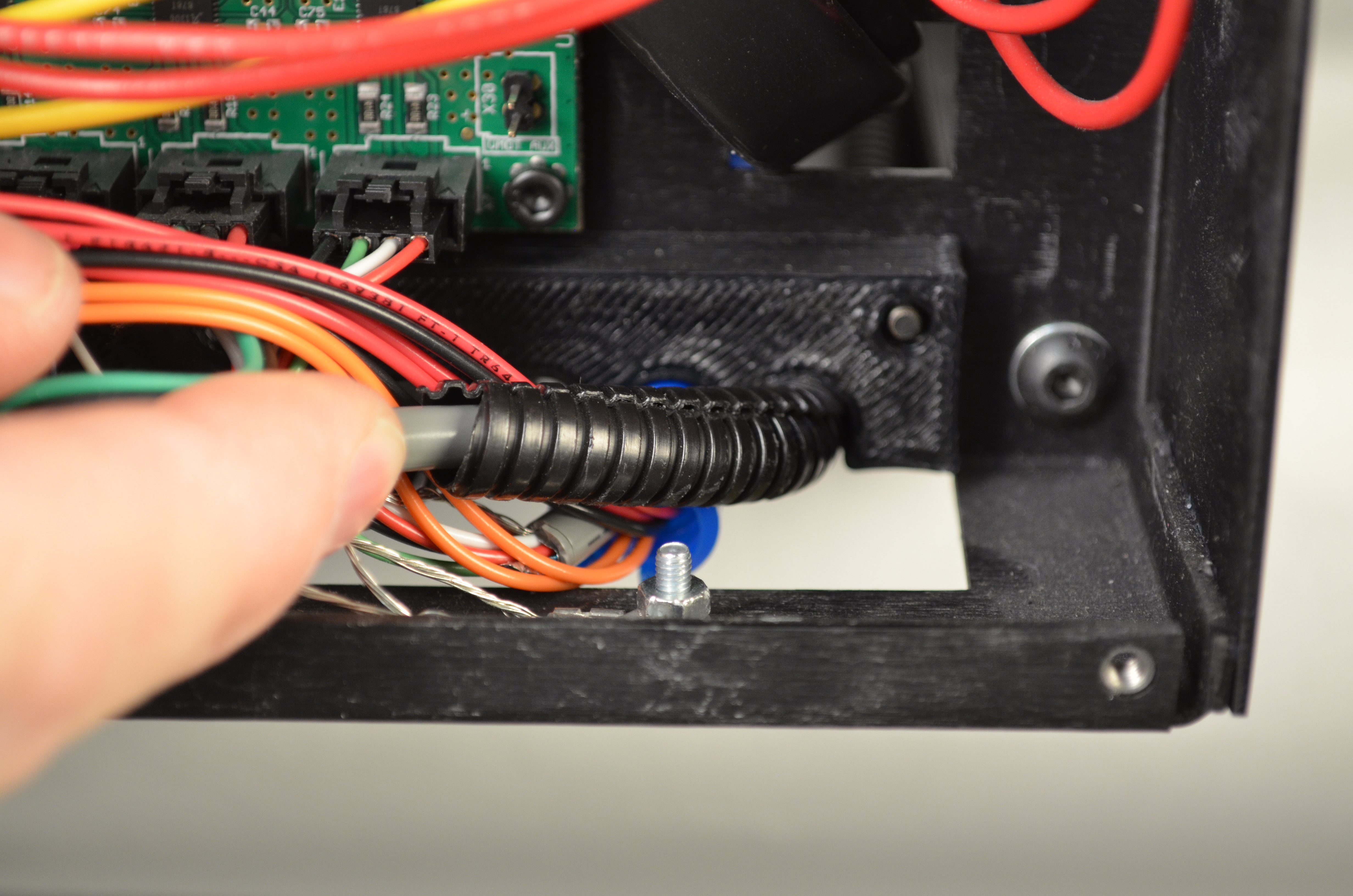
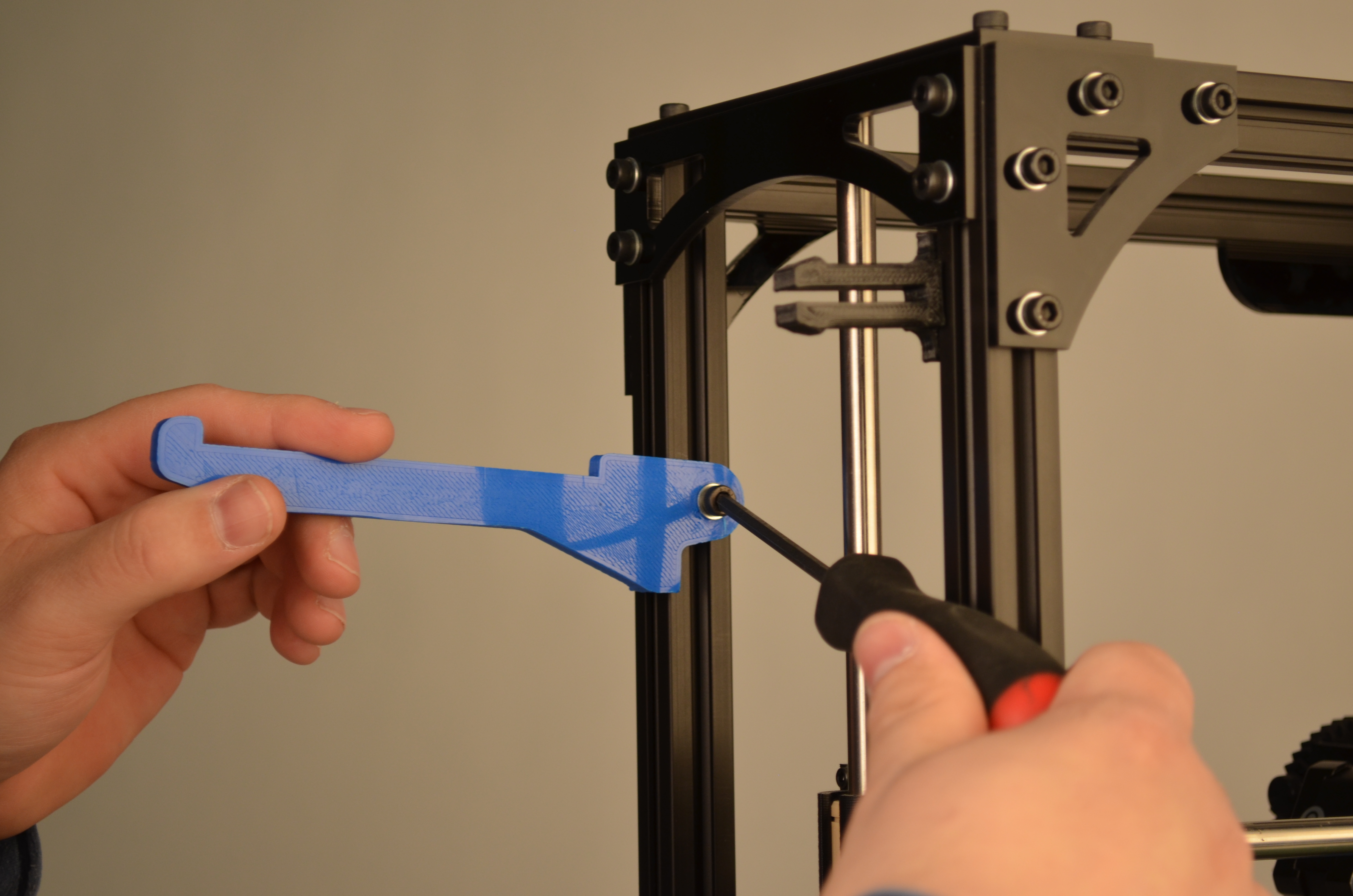
Remove the 3 M3 screws securing the strain relief plate to the electronics enclosure.

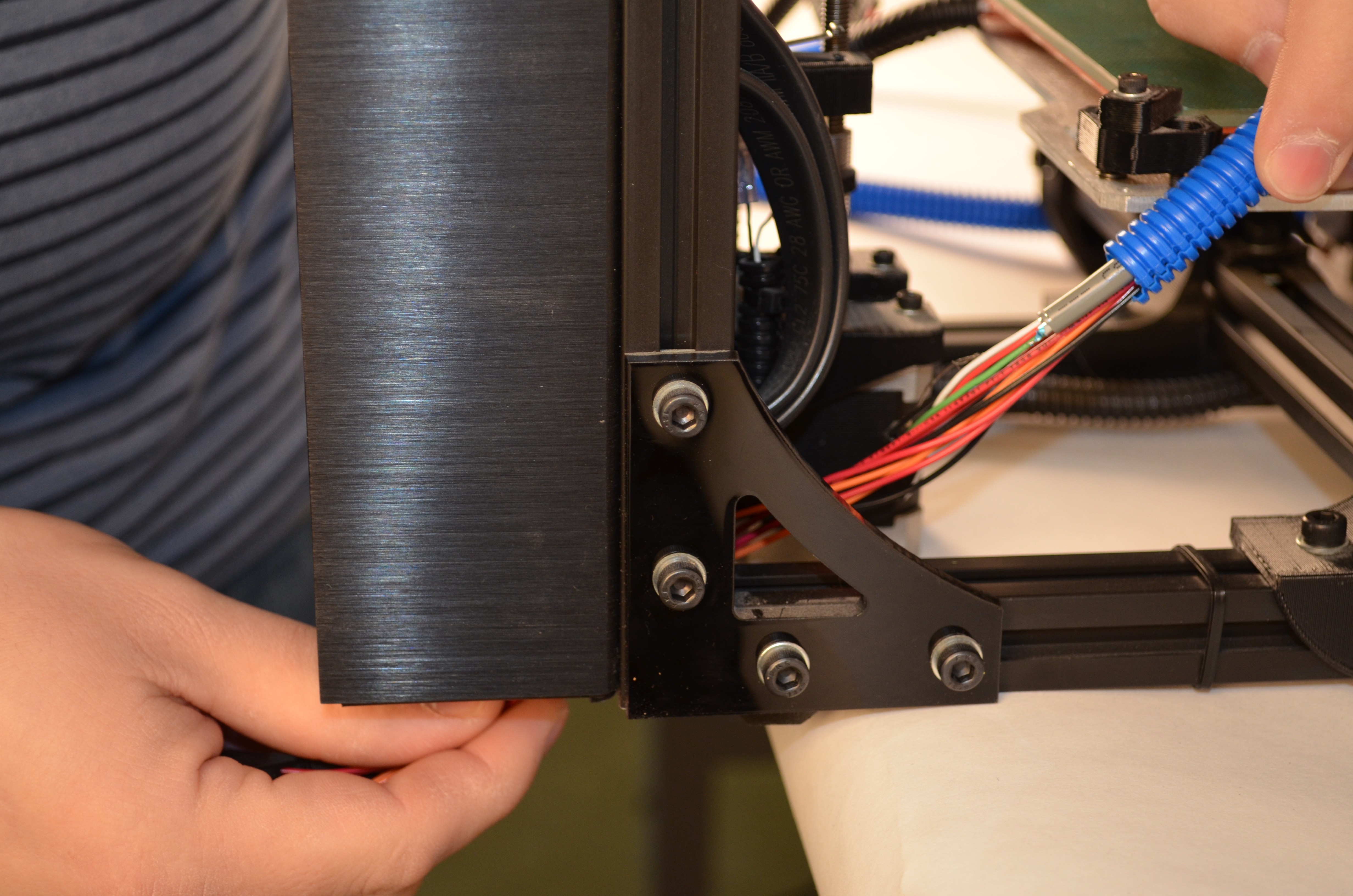
Insert the new additional wiring harness into the electronics enclosure, through the bottom of the case.
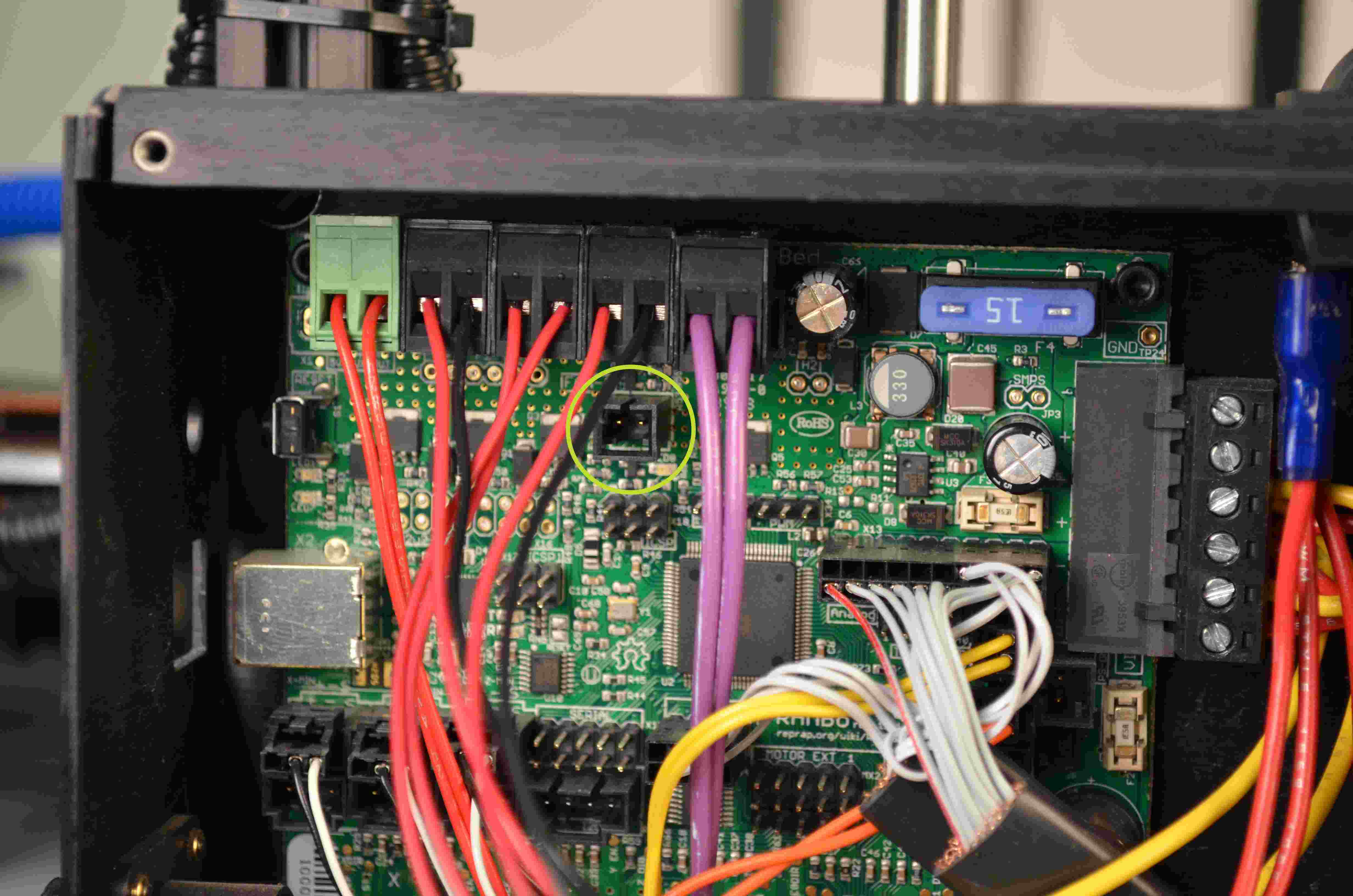
Plug in the red wired 2-pin connector into the RAMBo connector labeled Hot End 1 Heater.
If you have a second extruder fan, plug it in now, in the connection labeled Hot End 1 Fan.
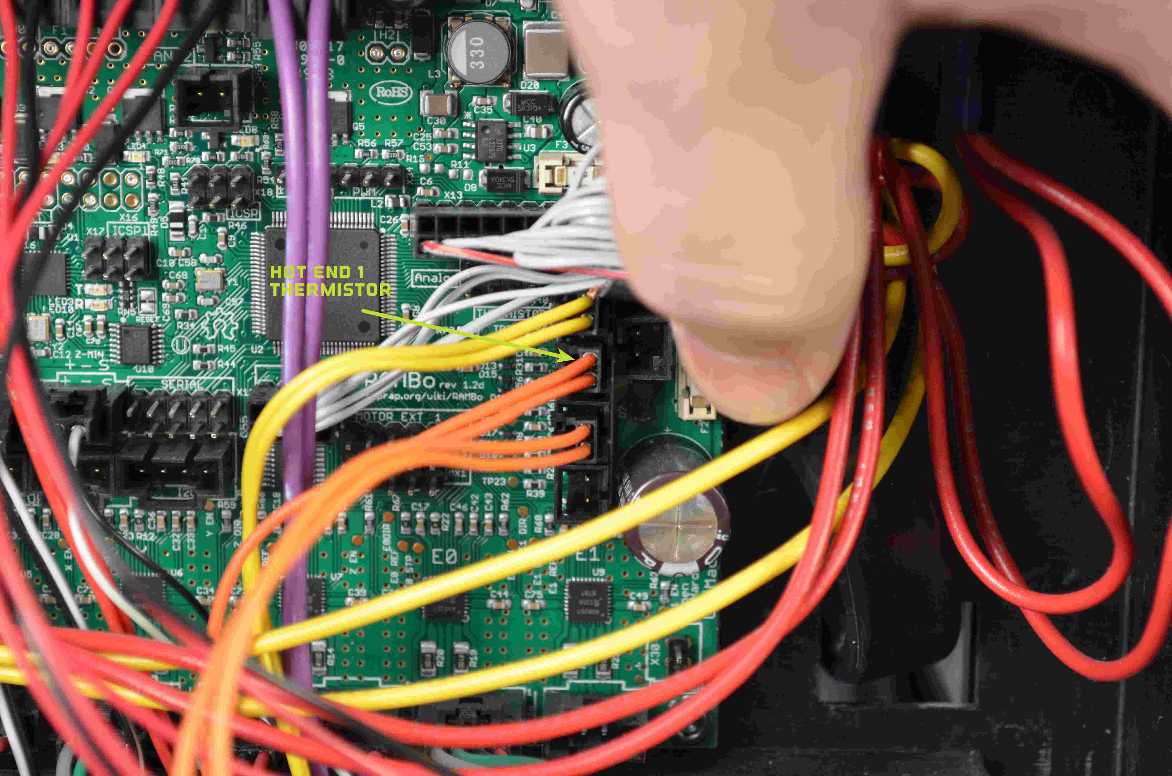
Plug in the orange wired 2-pin connector into the connection labeled Hot End 1 Thermistor.
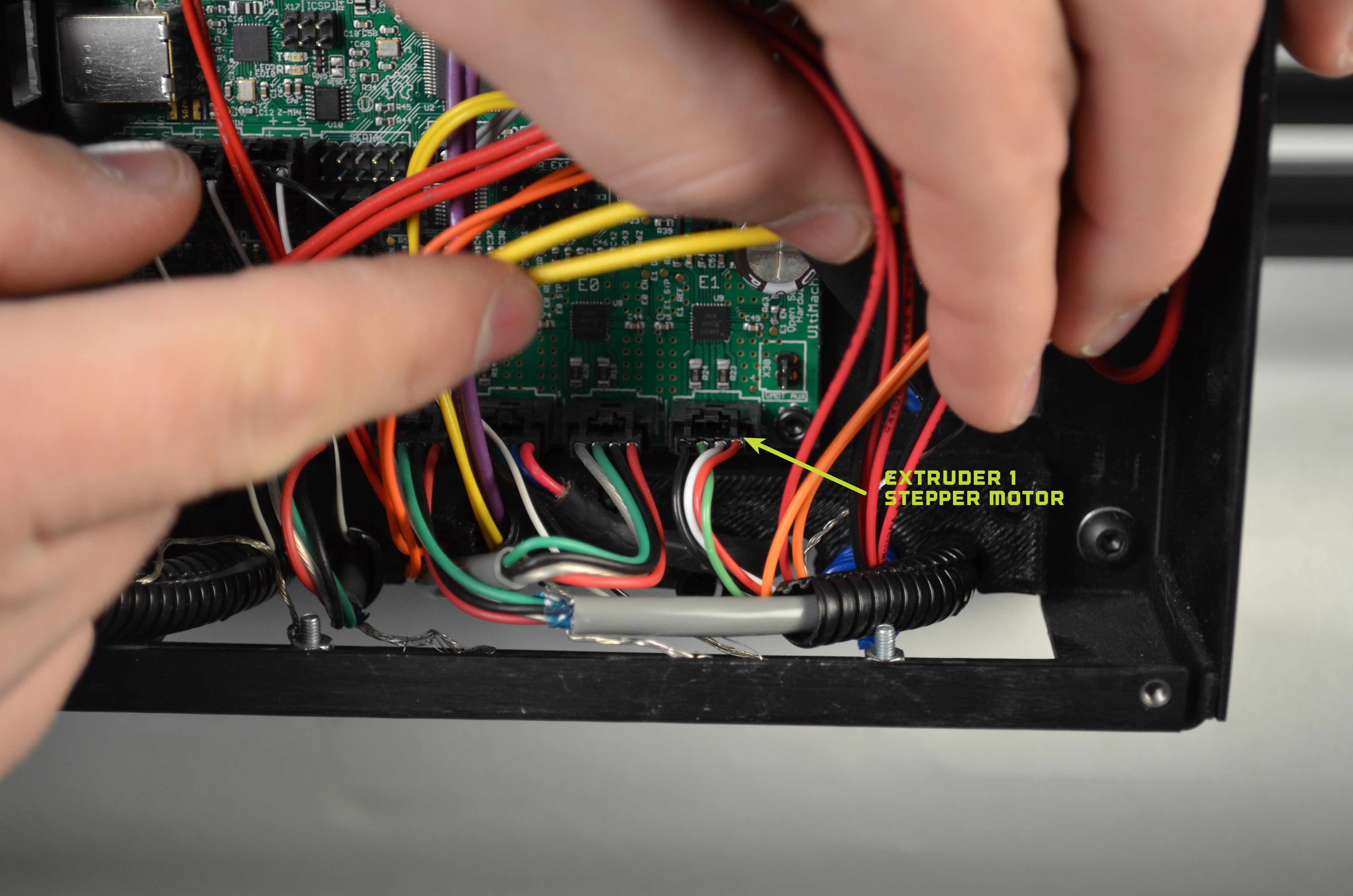
Plug in the multi-colored 4 Pin Connector into the connection labeled Extruder 1 Stepper Motor.

Align the wiring within the strain relief cutouts.
Slide the strain relief plate into place and secure with the 3 M3 screws.

Make sure that no wires will interfere with the electronics enclosure fan when putting the lid back in place. No wires should touch the fan blades.
Use the 4 M3 Screws to secure the cover.
Zip-tie the wire harness together if desired.
Use the original harness to group and cover the hot end wiring.
Use zip-ties to secure the wiring harnesses to the TAZ frame.
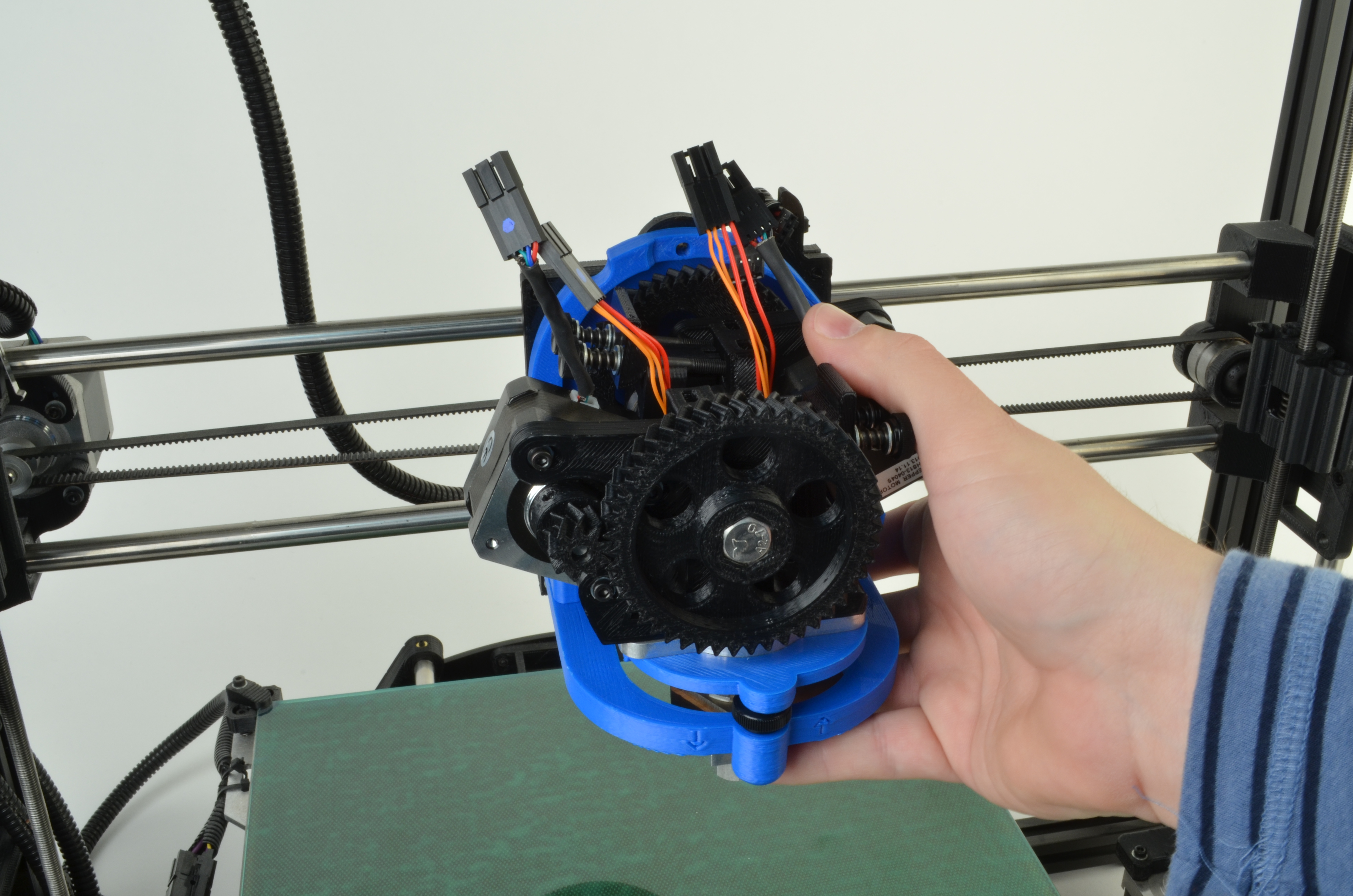
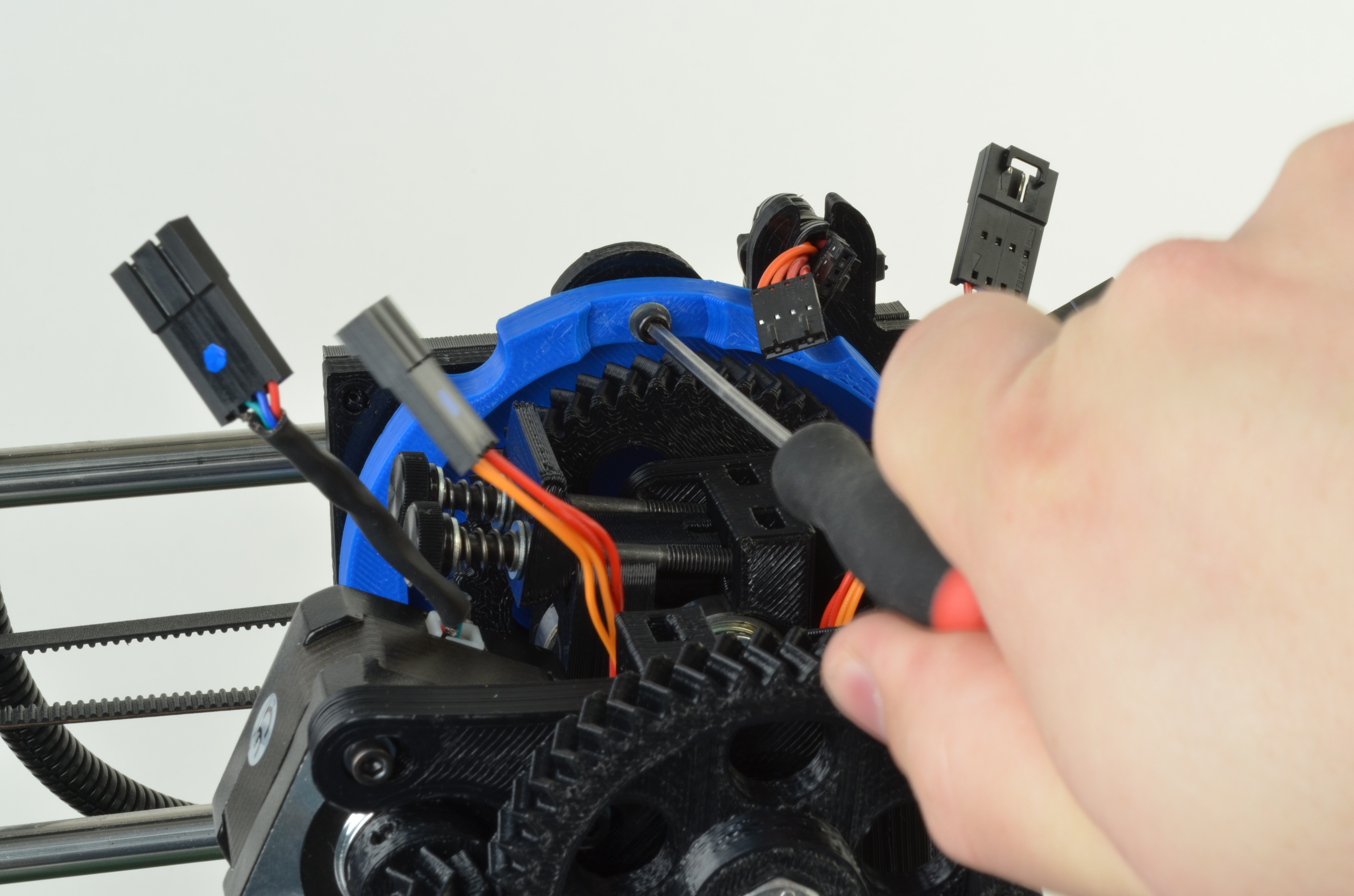
Connect the two extruders to the wiring harness:
Connect the rear extruder motor (extruder 0) 4 color wire connector to the 4 color wire connector within the black wiring harness
Connect the rear hot end (extruder 0) 2 color wire connector to the 2 color wire connector within the black wiring harness
Connect the front extruder motor (extruder 1) 4 color wire connector to the 4 color wire connector within the blue wiring harness
Connect the front hot end (extruder 1) 2 color wire connector to the 2 color wire connector within the blue wiring harness

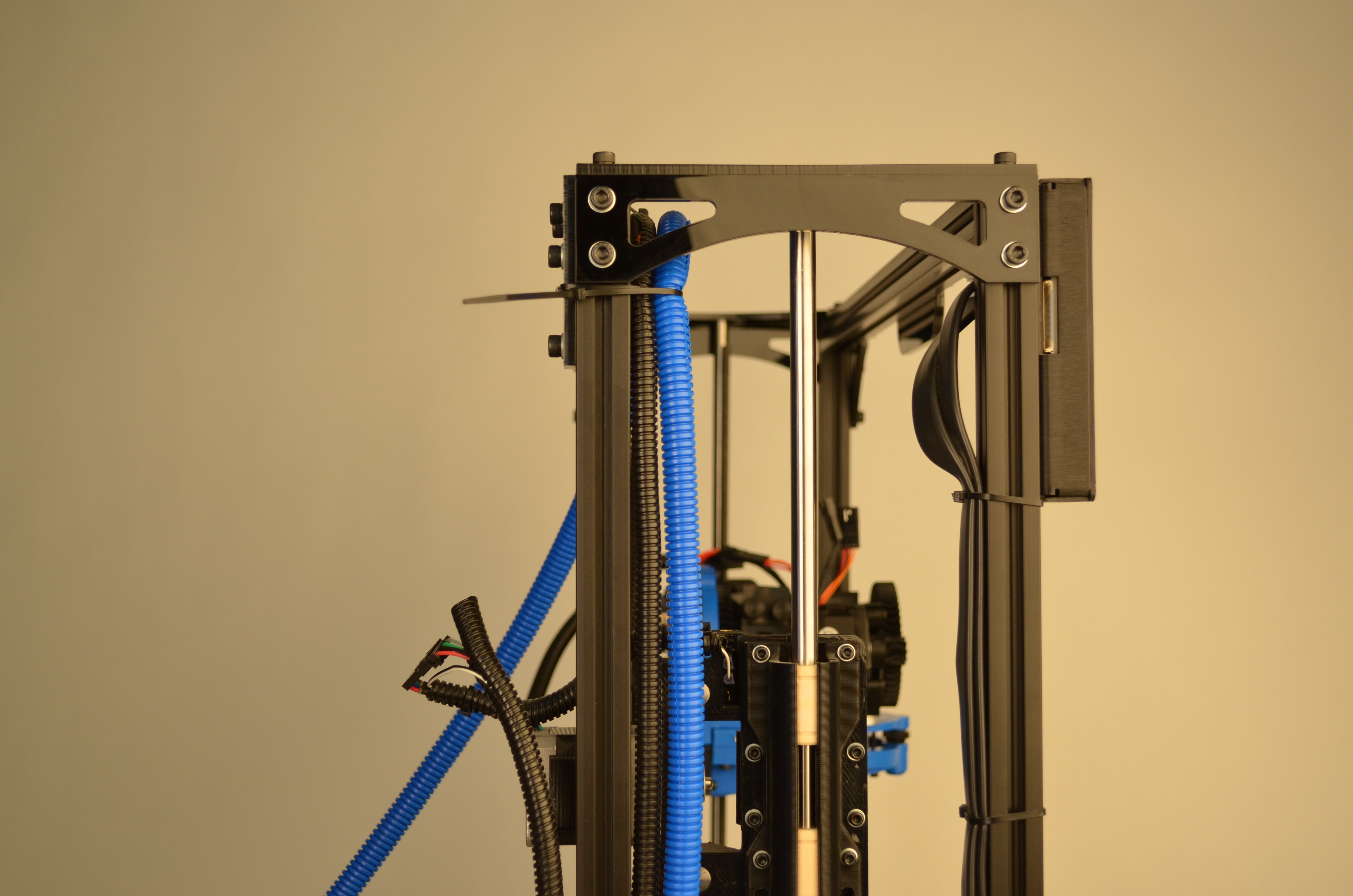
Loosen the M5 bolt holding the first spool arm.
Lower the exisiting spool arm by ~3 inches.
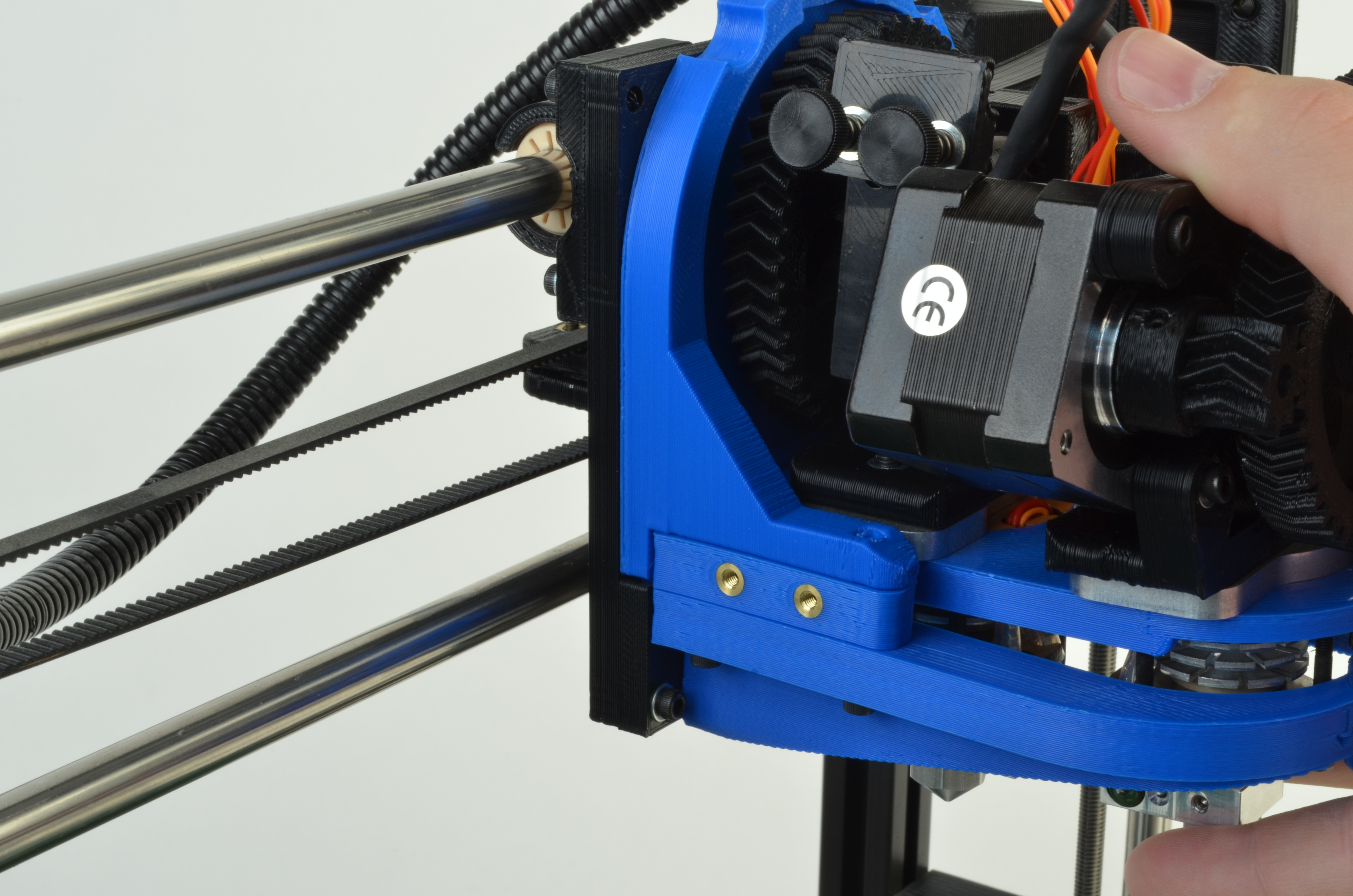
Attach 2nd spool arm using drop in fastener. Slide the provided M5 T-nut into the aluminum extrusion approximately 6” above the original spool arm position. Make sure that spools can spin freely on both arms without interfering with each other.
Attach 2nd feed tube on original feed tube holder.

On TAZ 1-3.1 printers, the Graphical LCD controller interferes with the dual extruder, limiting the maximum build area to about 200mm in the Z axis. To get back to the full build volume of the TAZ printer you will need to relocate the GLCD controller to the outside of the TAZ frame, just above the control box.
NOTE: this modification is not needed on TAZ 4 and newer TAZ printers.
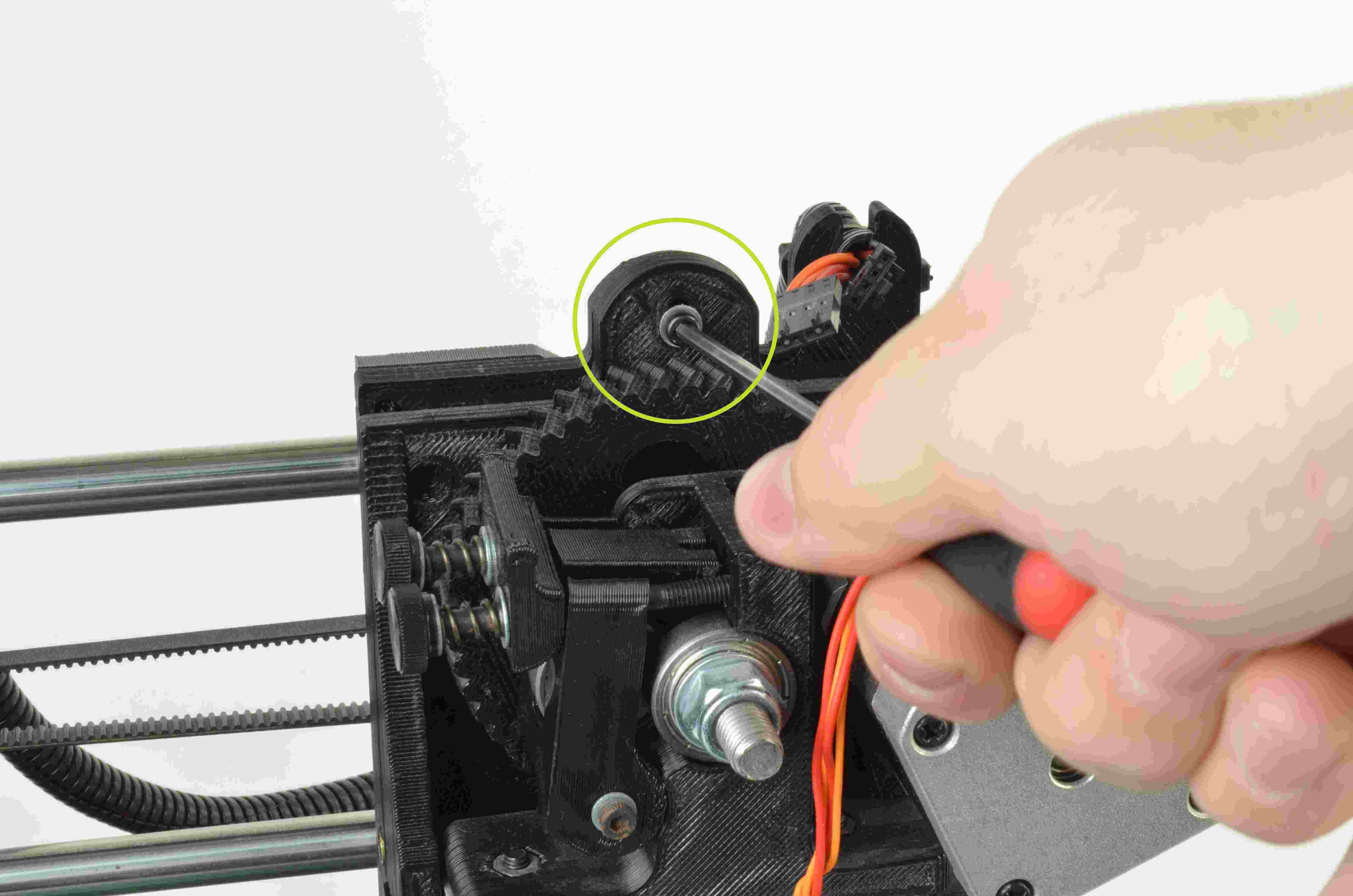
Using a 2.5mm driver remove 4 M3 screws on the front cover of the LCD screen.
Remove GLCD faceplate.
Using a 3mm driver remove 4 M5 screws holding GLCD to frame of printer. .
Unplug the two wiring harness from the back of the GLCD . Note the potisioning of each.
Shift GLCD over so that the 2 right bolts line up with the left extrusion on the printers frame.
Attach to the 2 T-Nuts captured in the piece of extrusion using 2 of the 4 M5 bolts you pulled out. This step is easier if you tilt the printer onto it's back side so the T-nuts don't slide around. Ideally, the GLCD controller will be slightly lower than the top extrusions.
Attach GLCD front plate with the 4 M3 screws removed earlier.
Plug GLCD back in (you'll need to clip the top zip tie to get them to reach or slide down the zip tie).
Use the firmware found here: Devel.LulzBot.com
Power on the TAZ 3D printer. Plug your TAZ 3D printer into your computer using the USB cable that was provided with your printer.
Locate your original steps per unit.
Update your local Arduino installation with the required libraries using this guide
Extract the files to a memorable location.We recommend a new folder on your Desktop, or a new folder in your Home folder.
Extract the Firmware archive. Once extracted, you should have the following folders:
Open the Arduino IDE.
Select File > Open .
Navigate to the folder containing the Marlin folder you previously extracted.
Open the file titled Marlin.ino
Once opened, you should see multiple tabs across the top of the Arduino IDE window.
In the Configuration.h tab, update the information found in:
DEFAULT_AXIS_STEPS_PER_UNIT
You will need to update the last 800 number with the Estep value found earlier.
On the next line:
define DEFAULT_E1_STEPS_PER_UNIT 800 // default steps per unit for second extruder
change the 800 value to 840.
Once changed save the modifications by pressing CTRL & S or by selecting in the menu File > Save.
Connect the TAZ to your computer with the supplied USB cable.
Once connected, in the Arduino IDE menu, select:
Upload the firmware to the TAZ 3D printer by selecting File > Upload Sketch or by pressing Ctrl & U.
The firmware will now compile, then will upload to the board. Once finished, the Arduino IDE will display a completion message.
If you encounter any errors, contact support by sending an email to Support@LulzBot.com