Open HardwareAssembly Instructions
Guides for installation and assembly of the LulzBot line of products made by FAME 3D LLC.
Guides for installation and assembly of the LulzBot line of products made by FAME 3D LLC.
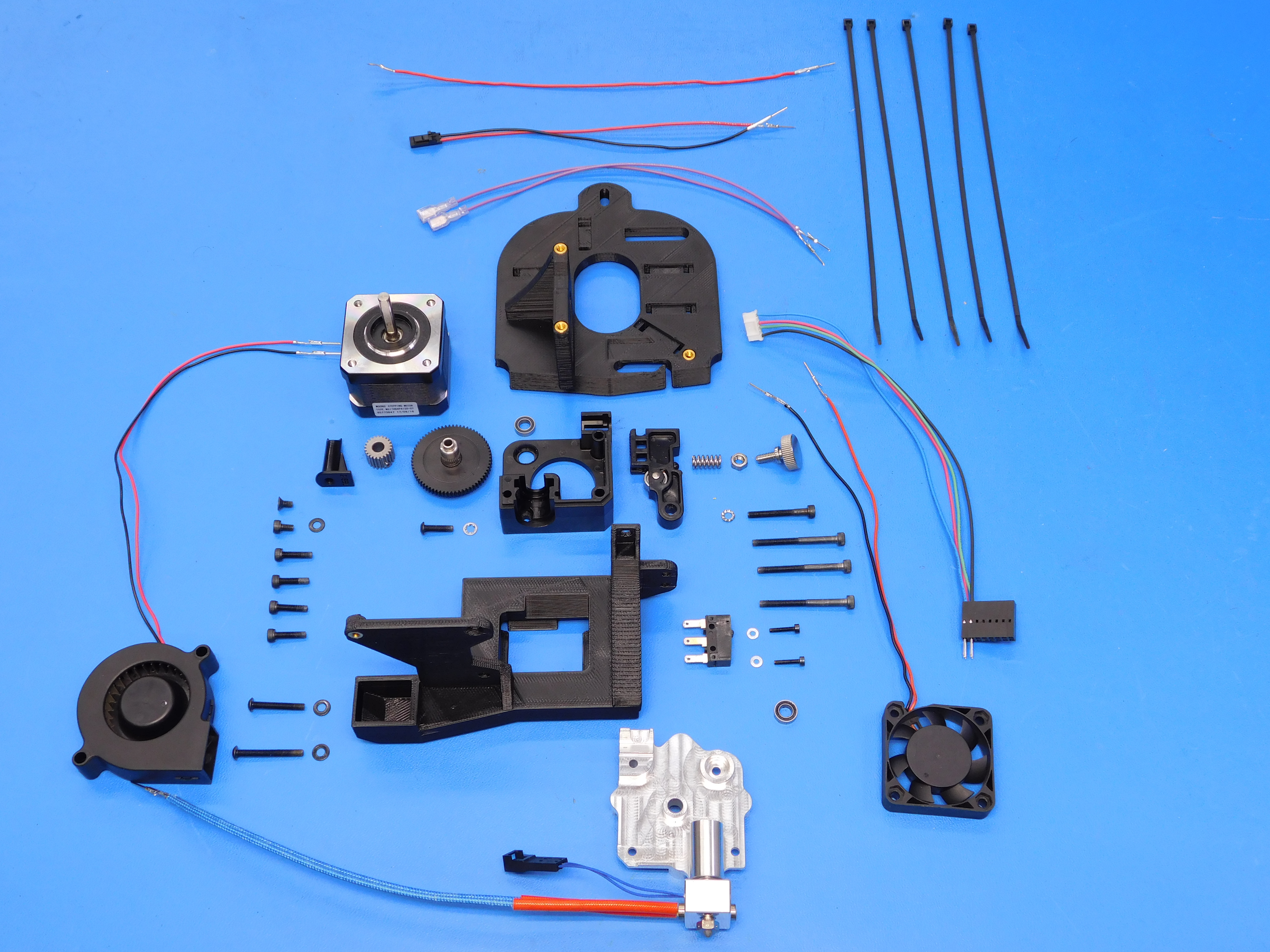
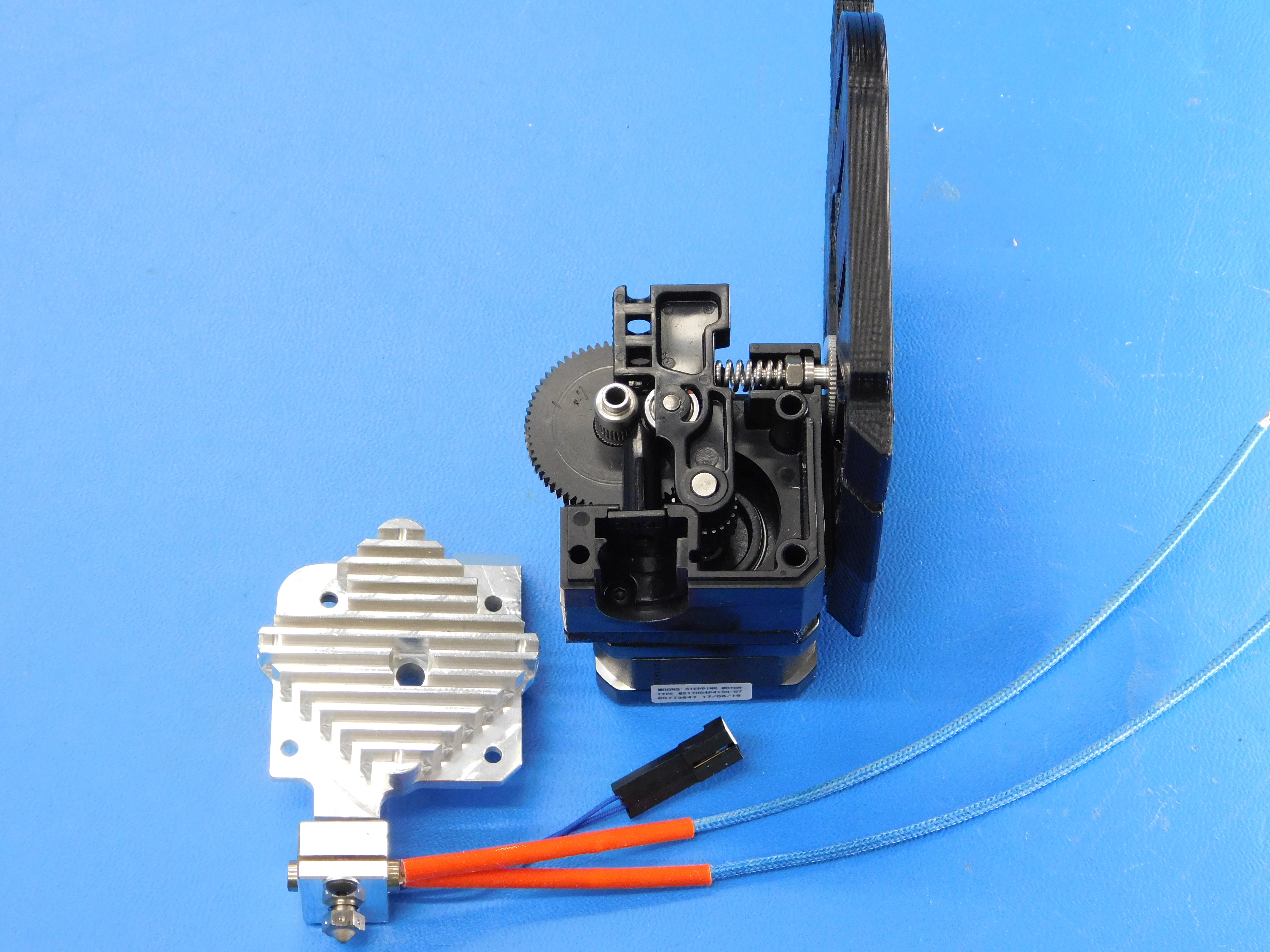
Gather the following parts:
1x- TAZ Aero Hotend Assembly (AS-HE0019)
1x- E3D Aero Idler Lever (PP-FP0135)
1x- E3D Mirrored Aero 2.85mm Filament Guide (PP-FP0136)
1x- E3D Aero Acetal Gear w/ Filament Drive Shaft (PP-FP0137)
1x- Aero Mirrored Body w/ Threaded Insert (PP-MP0204)
1x- E3D Aero Steel Pinion Gear w/ set screw (PP-MP0282)
1x- Blower Fan (AS-CB0044)
1x- Extruder Motor Harness (AS-CB0045)
1x- Heatsink Fan (AS-CB0046)
1x- Hotend Ground Wire (AS-CB0047)
1x- Thermistor Harness (AS-CB0048)
2x- X-Max Switch Harness (AS-CB0049)
1x- TAZ Aero Blower Shroud w/ Inserts (PP-IS0038)
1x- TAZ Aero Extruder Mount w/ Inserts (PP-IS0039)
1x- Half Height Moons’ Stepper Motor (EL-MT0040)
1x- End Stop Switch (EL-SW0022)
2x- M2x10 SHCS (HD-BT0107)
2x- M2 Washers (HD-WA0012)
1x- M4 Thumb Screw (HD-BT0197)
1x- Idler Spring (HD-MS0430)
1x- M4 Nut (HD-NT0011)
4x- M3x12 SHCS (HD-BT0039)
1x- M3x5 SHCS (HD-BT0044)
3x- M3x35 SHCS (HD-BT0043)
1x- M3x25 SHCS (HD-BT0041)
1x- M3x6 FHCS (HD-BT0128)
1x- M3x12 BHCS (HD-BT0146)
1x- M3x20 BHCS (HD-BT0171)
1x- M3x25 BHCS (HD-BT0202)
2x- MR95ZZ Bearings (HD-MS0446)
1x- Internal Tooth Lock Washer (HD-WA0027)
1x- External Tooth Lock Washer (HD-WA0035)
3x- M3 Black Washers (HD-WA0038)
5x- 8” Black Wire Ties (HD-MS0058)
1x- Tool Head Wiring Connector Alignment Label (DC-LB0104)
Tools Required:
2.5mm Hex Driver
2mm Hex Driver
1.5mm Hex Driver
3 IN-LBS Torque Driver w/ 2.5mm Hex Bit
5 IN-LBS Torque Driver w/ 1.5mm Hex Bit
Clippers
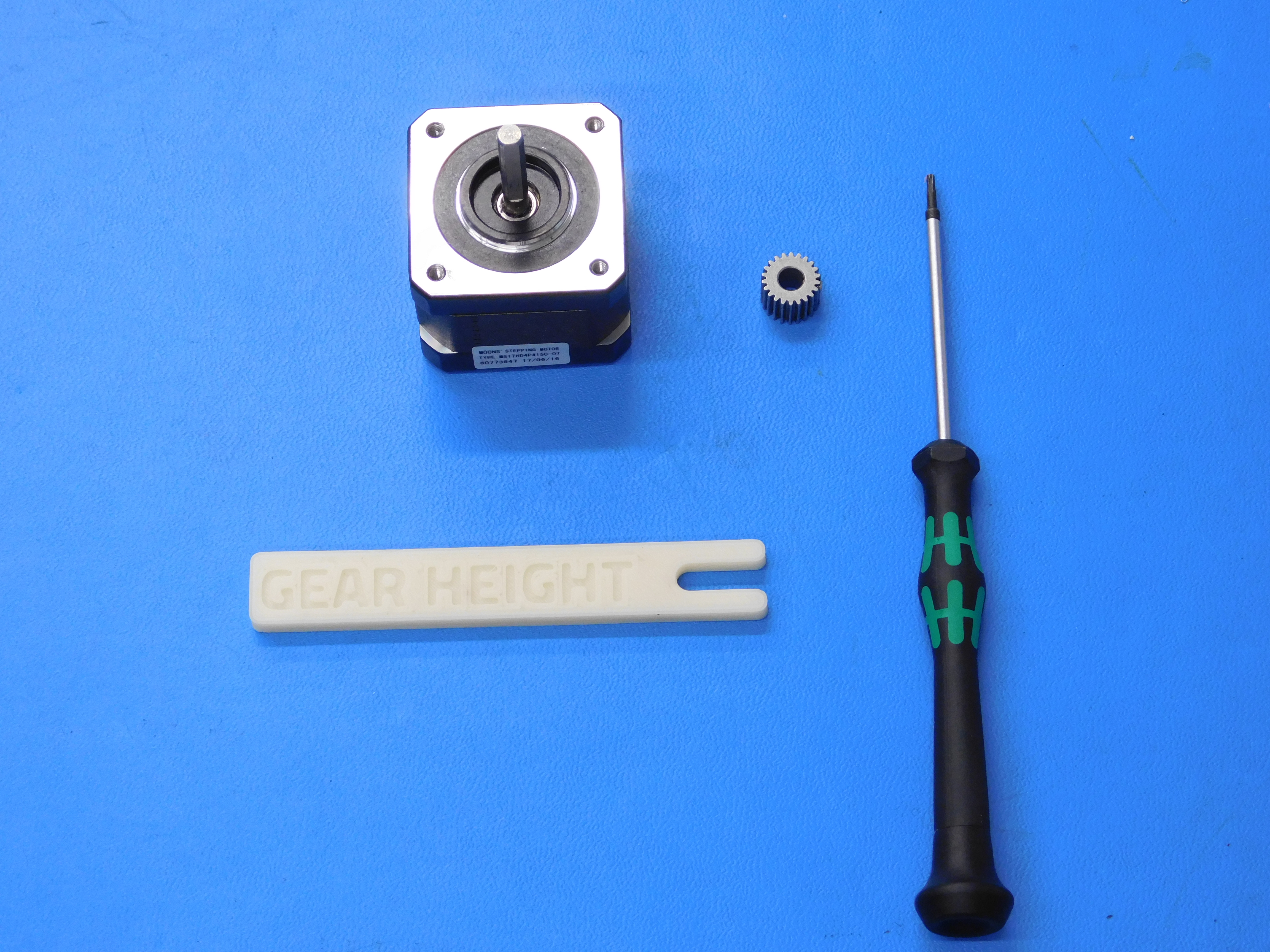
AeroStruder Gear Spacer
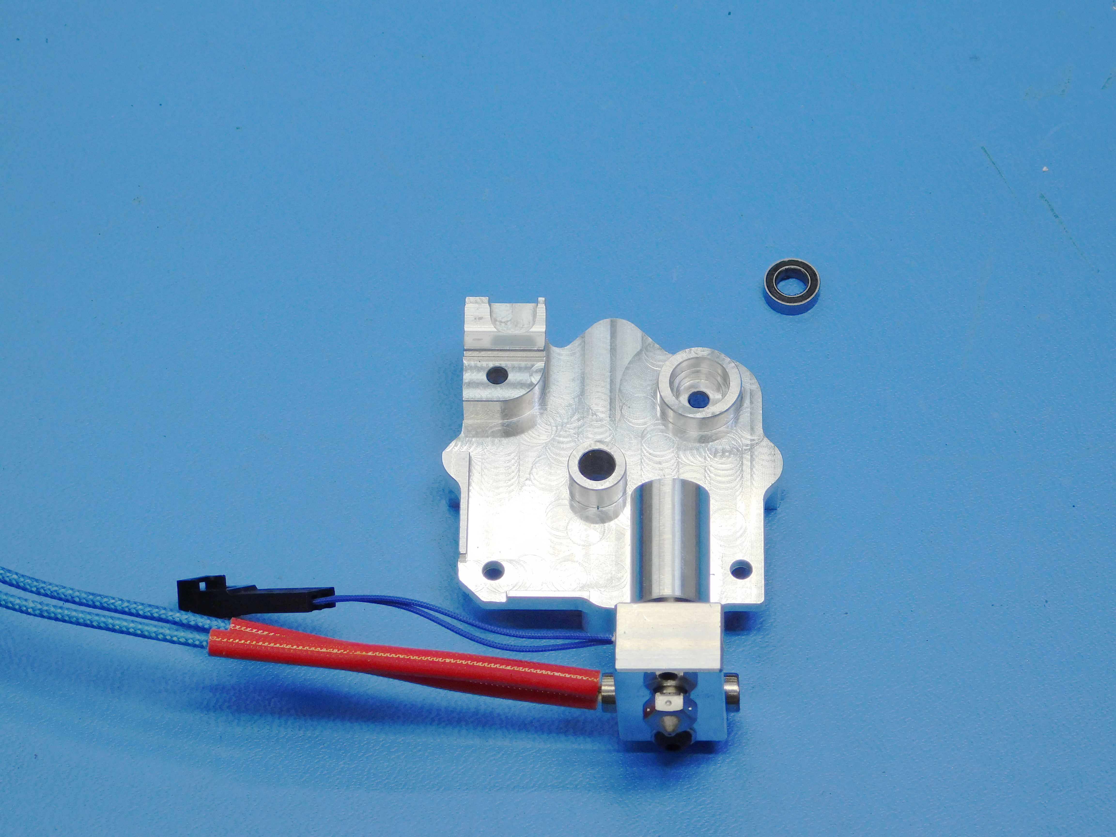
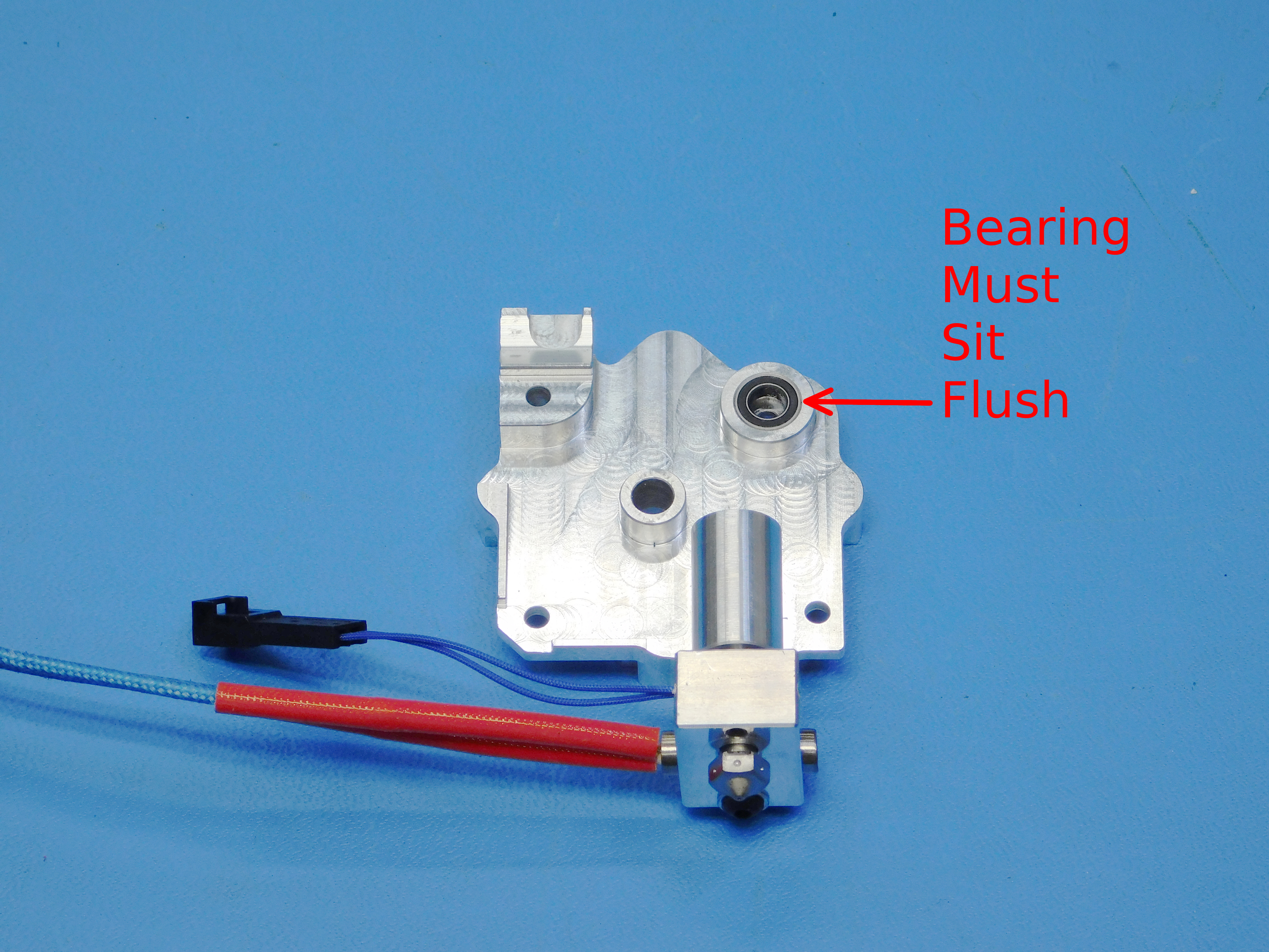
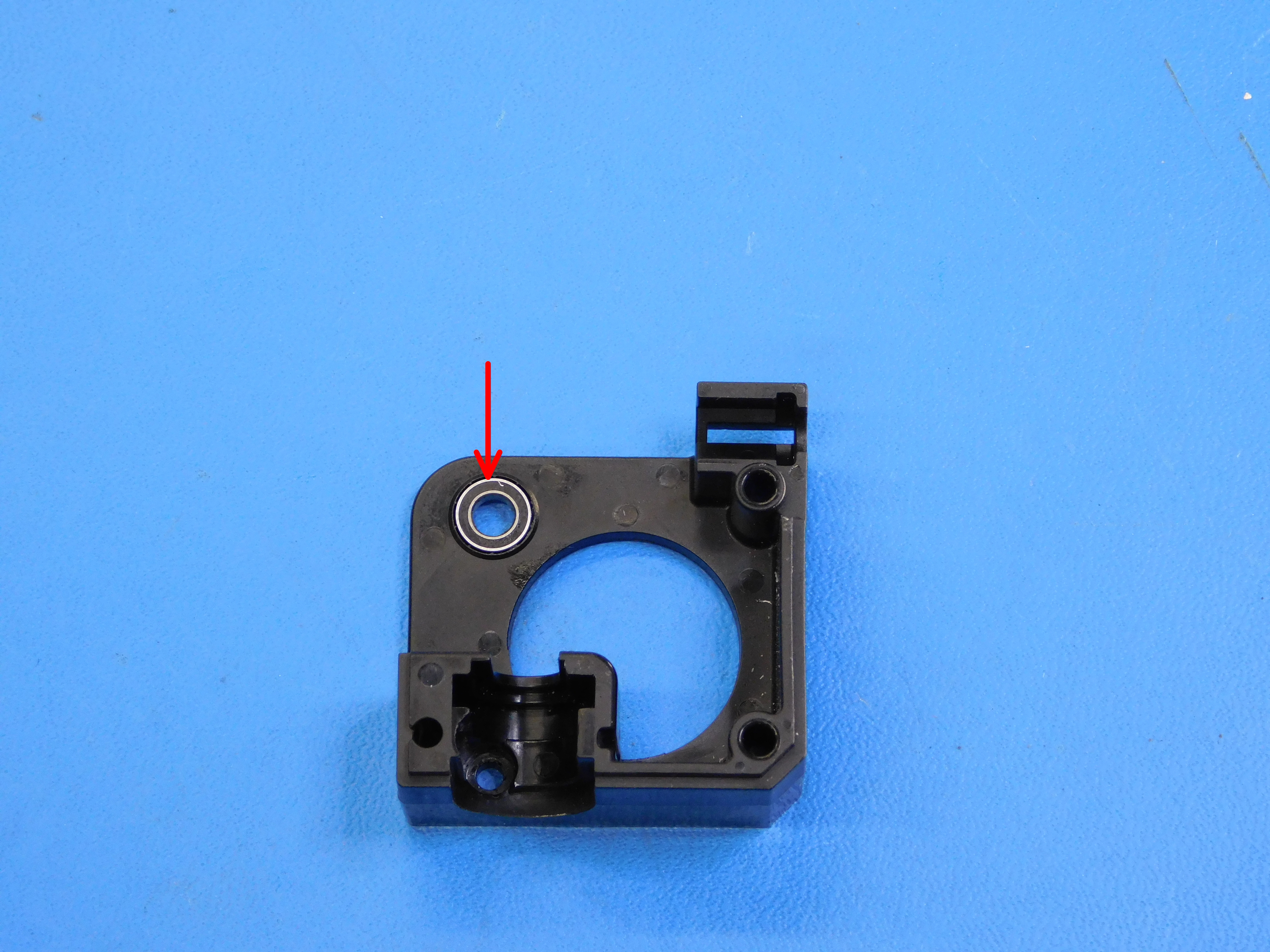
Install the bearing [HD-MS0446] into the heatsink [AS-HE0019] as shown.
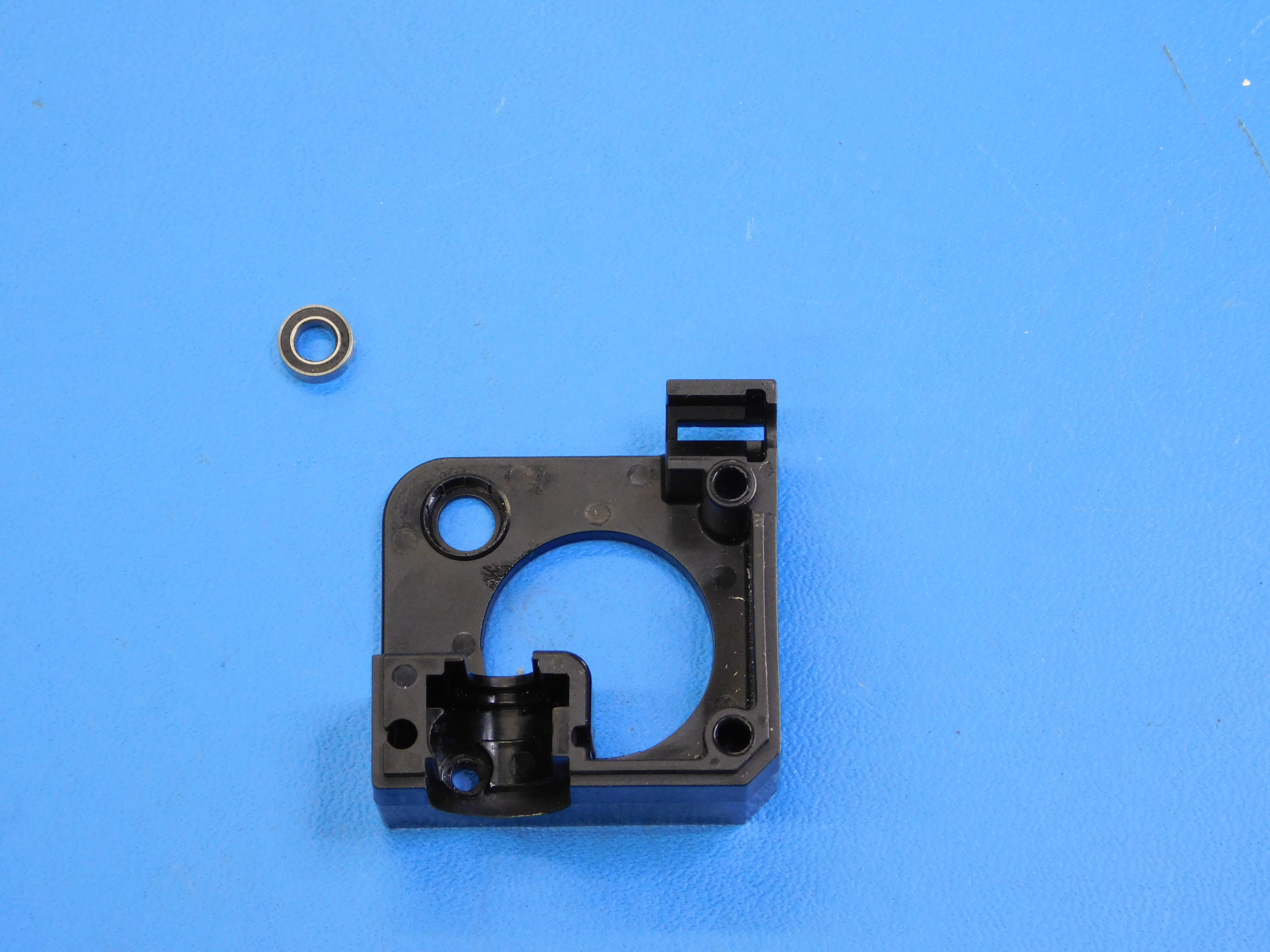
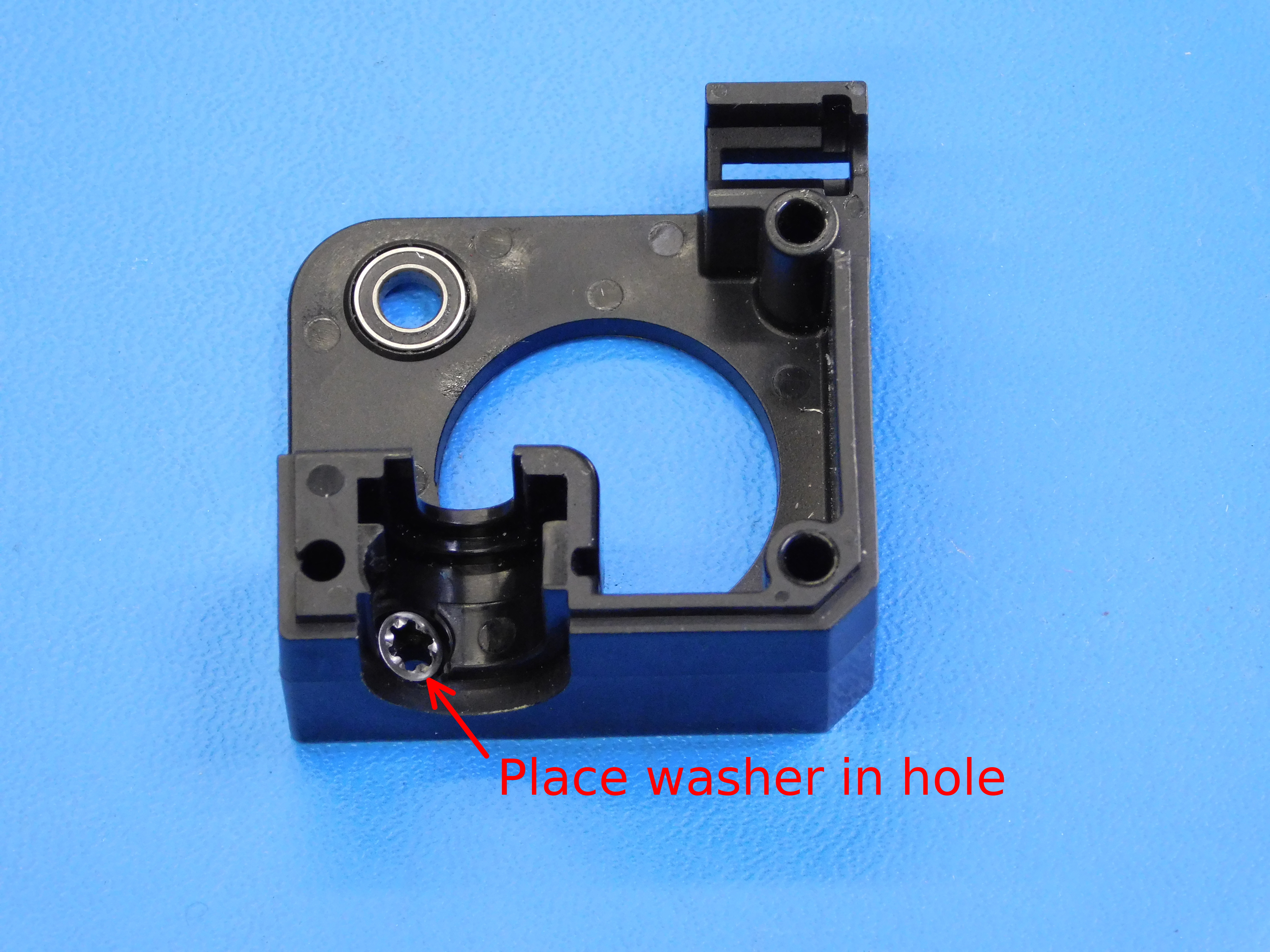
Insert the internal lock washer [HD-WA0027] into the injection molded extruder body [PP-MP0204] as shown.
Insert the remaining MR95ZZ Bearing [HD-MS0446] into the extruder body [PP-MP0204] as shown.

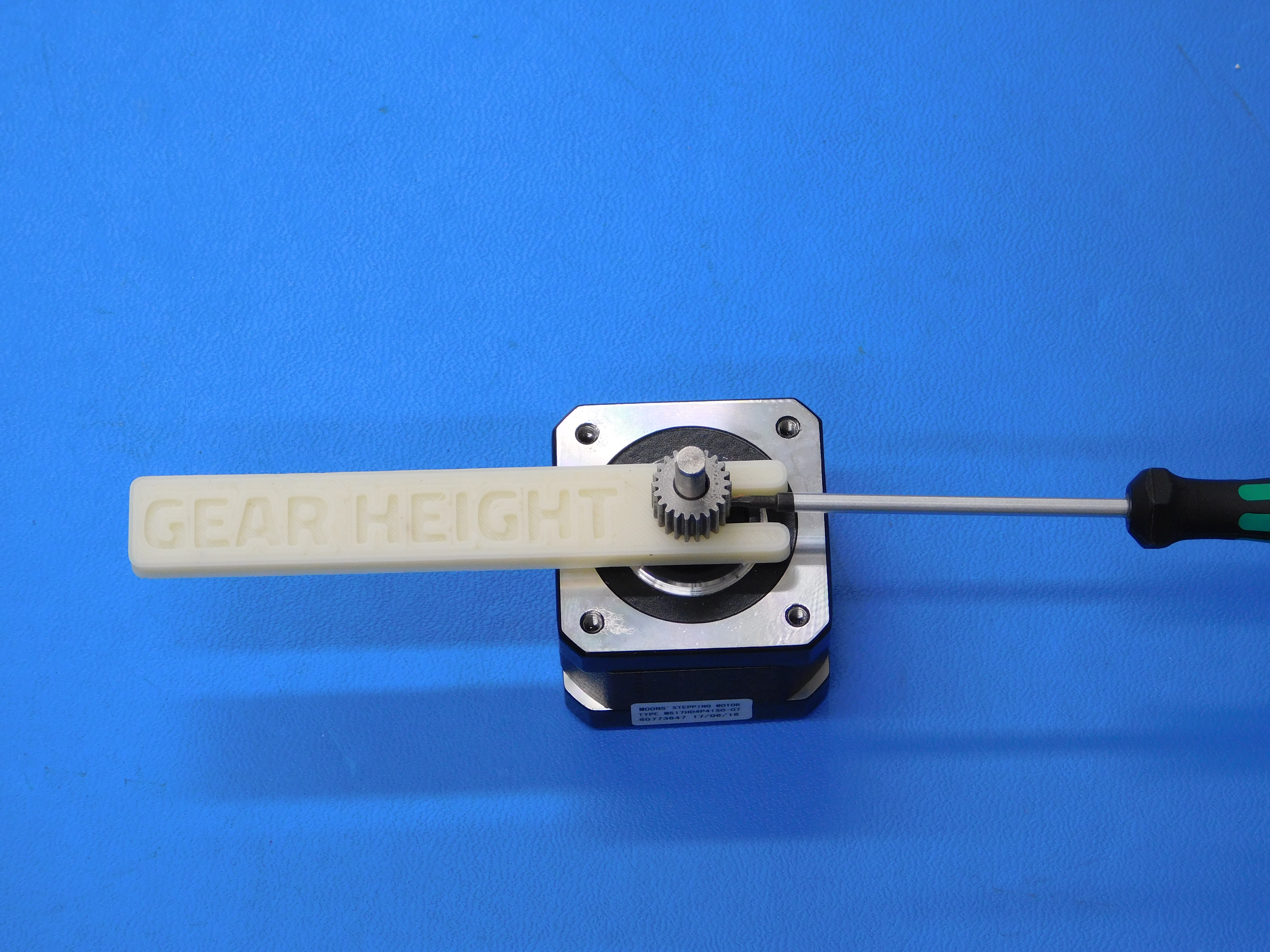
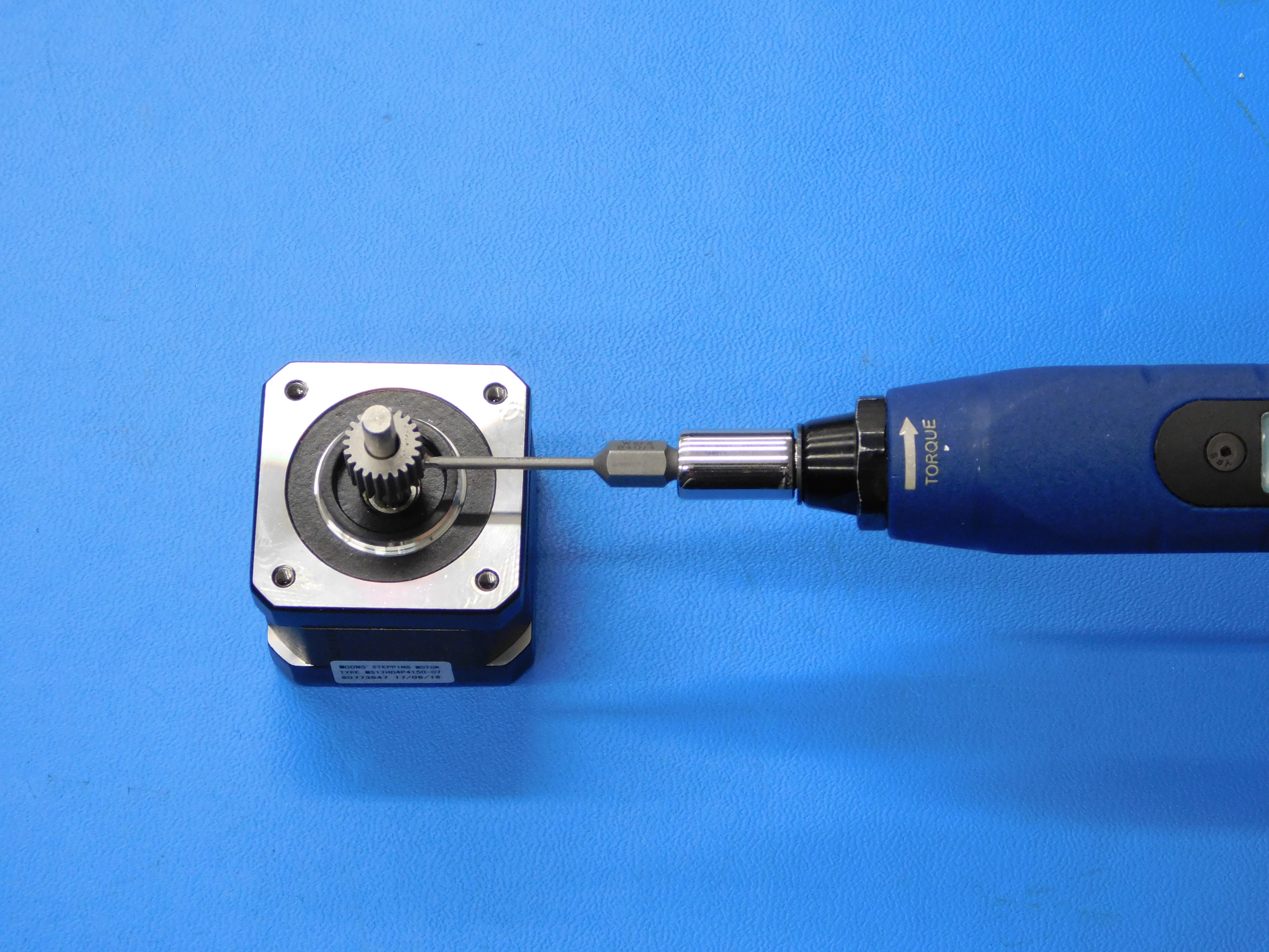
Install the small gear [PP-MP0282] onto the shaft of the motor [EL-MT0040] using the printed spacer to achieve the correct height.
Apply Blue Loctite and torque the set screw to 3 in*lbs.
A set screw should come pre-installed in the gear, if not, ensure an M3x3 set screw is used. Set screws of any greater length will interfere with the larger gear during operation.
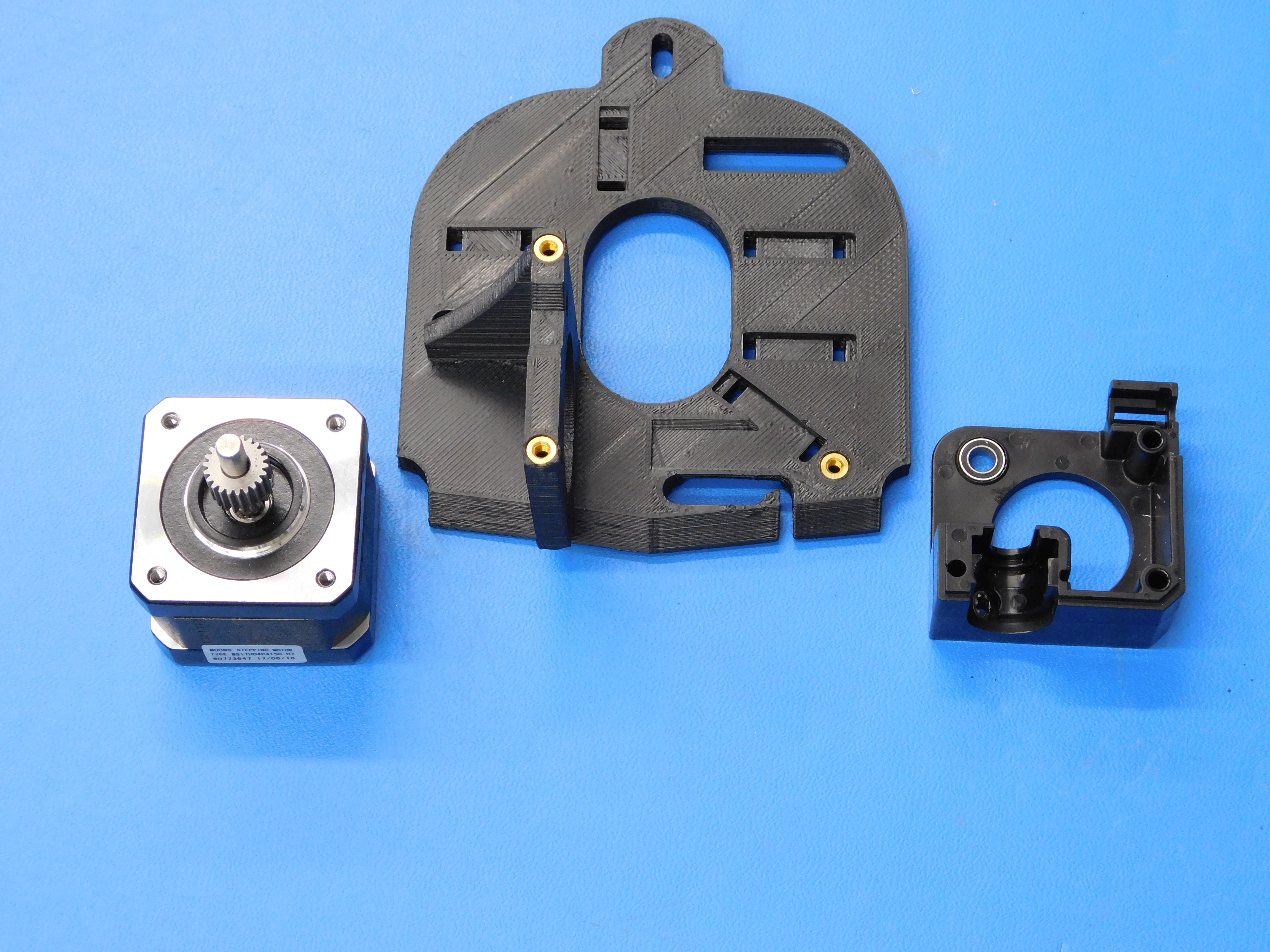
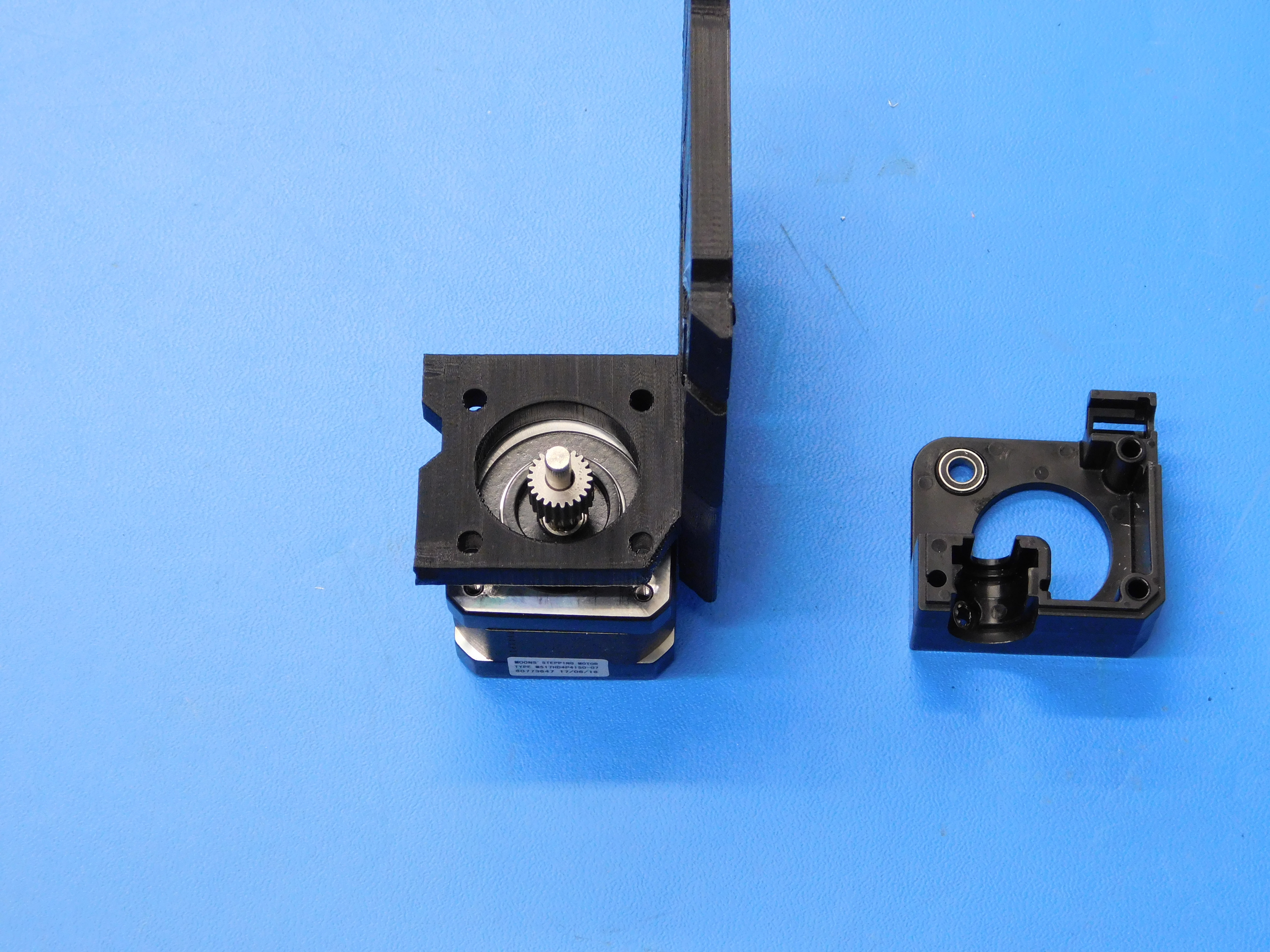
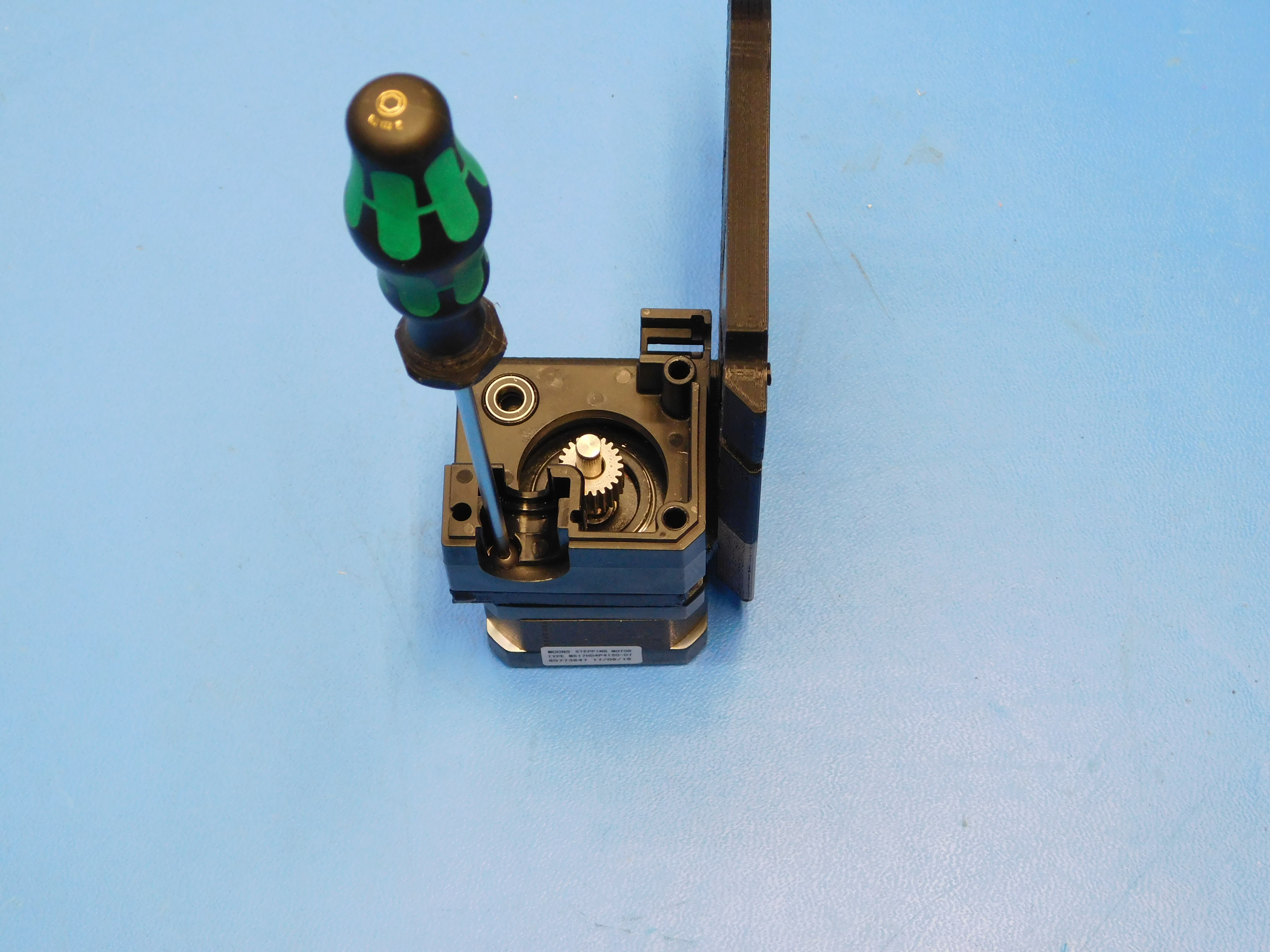
Install the motor and gear assembly and extruder body [PP-MP0204] as shown using one M3 x 12 BHCS [HD-BT0146]. Torque to 5in*lbs
Ensure the motor’s connector is facing the top of the Extruder Mount.
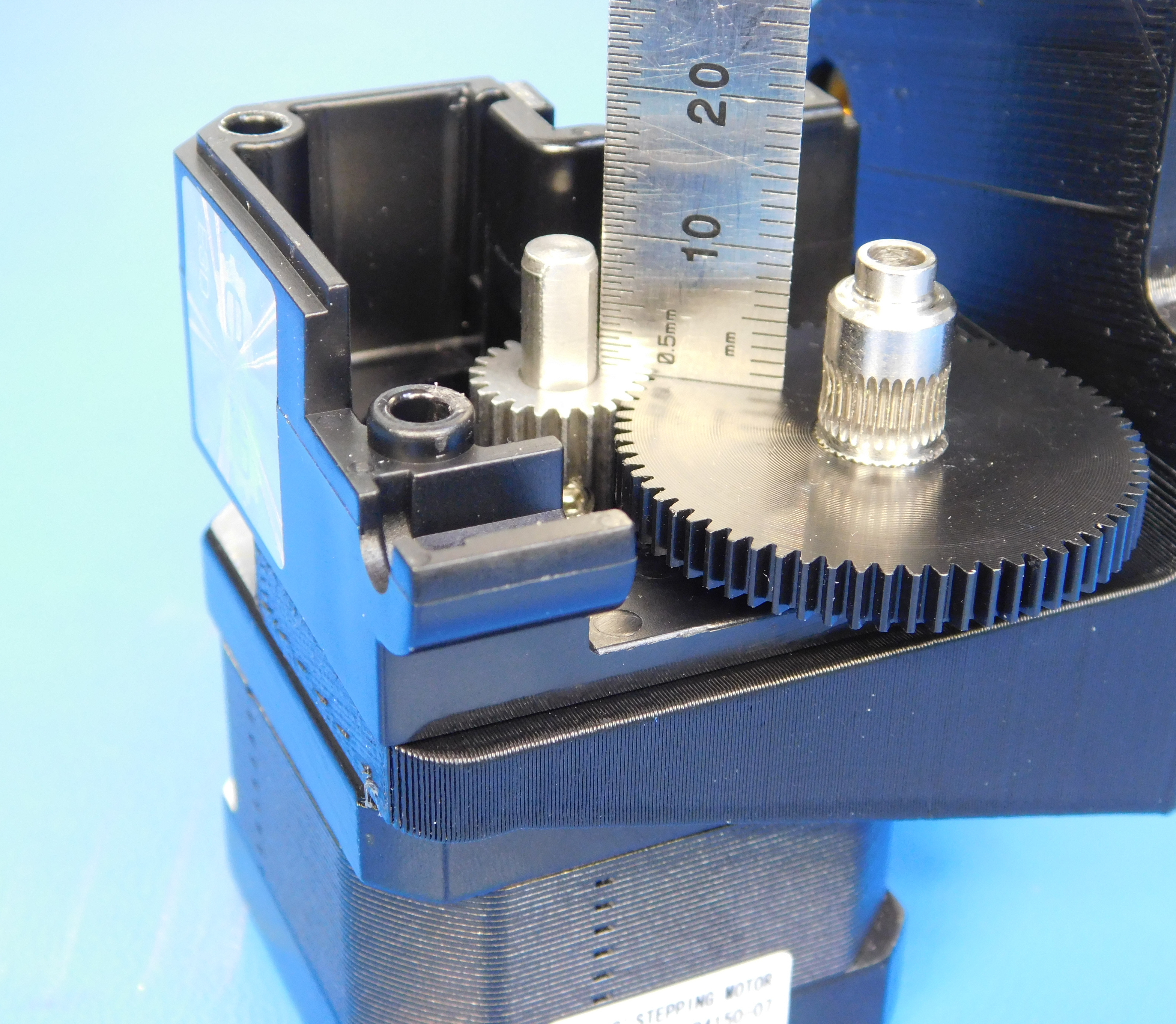
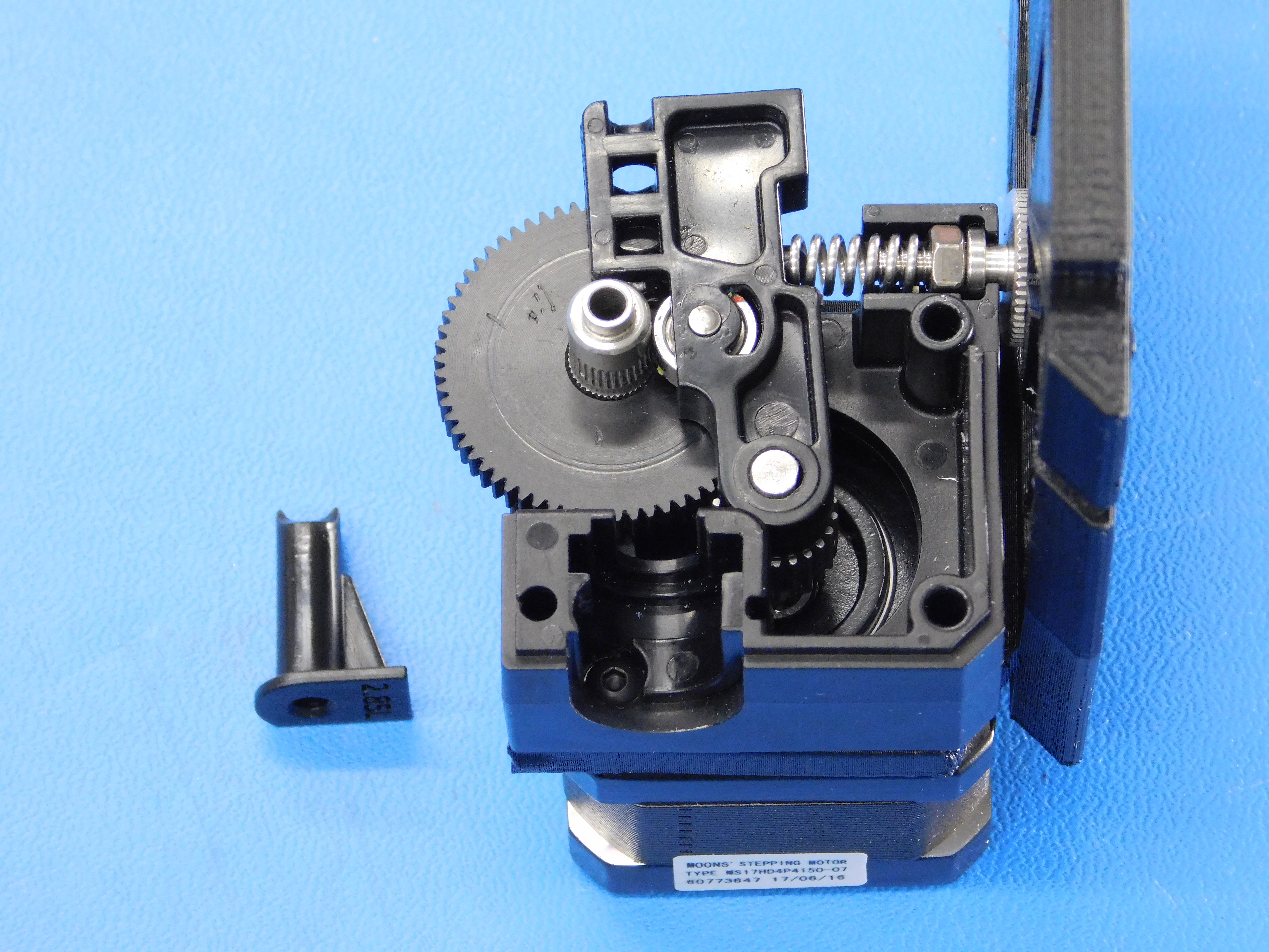
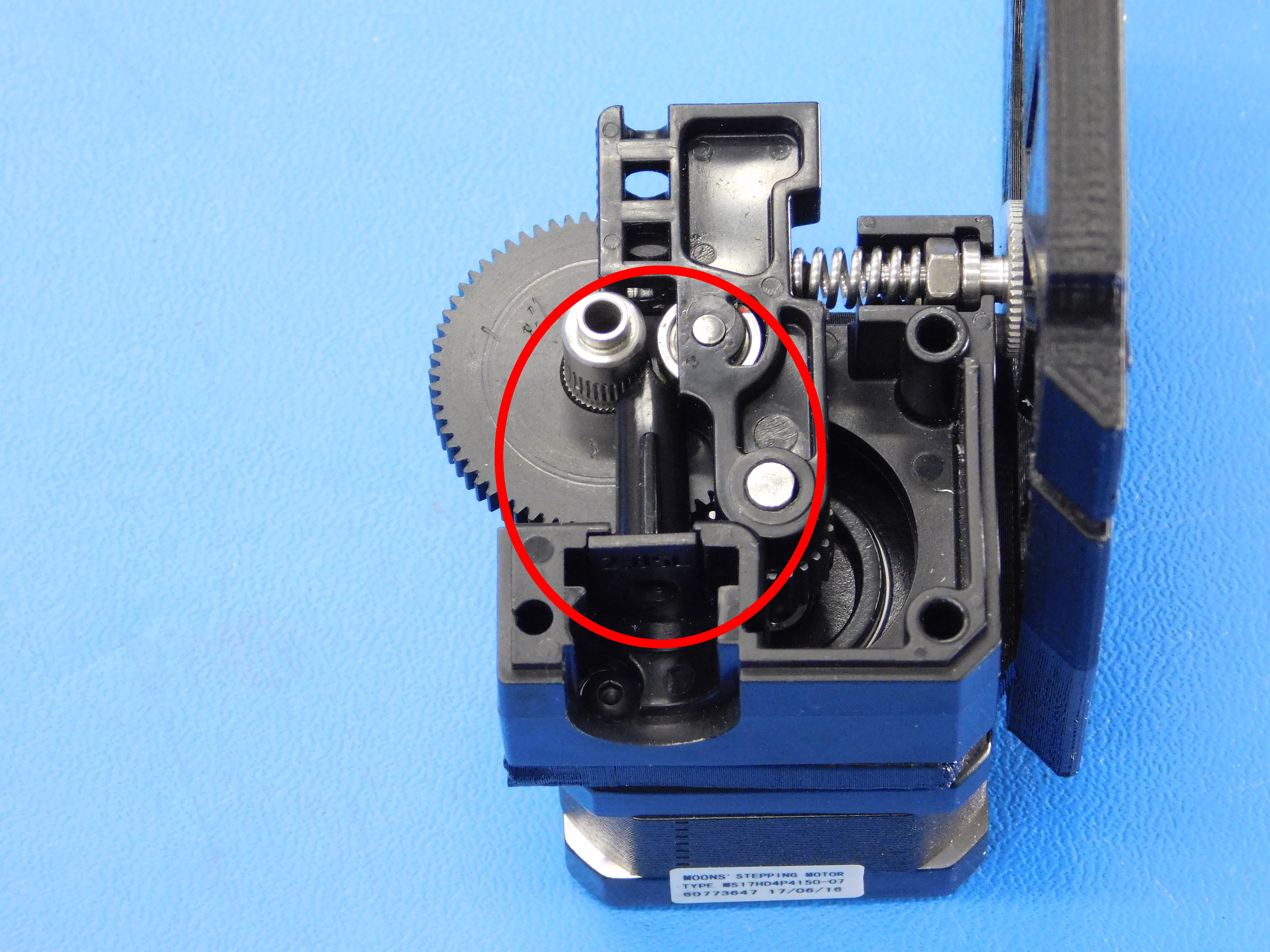
Install the large gear and hobb assembly [PP-FP0137] as shown.
Check to make sure the top surfaces of both gears mate flush as shown.


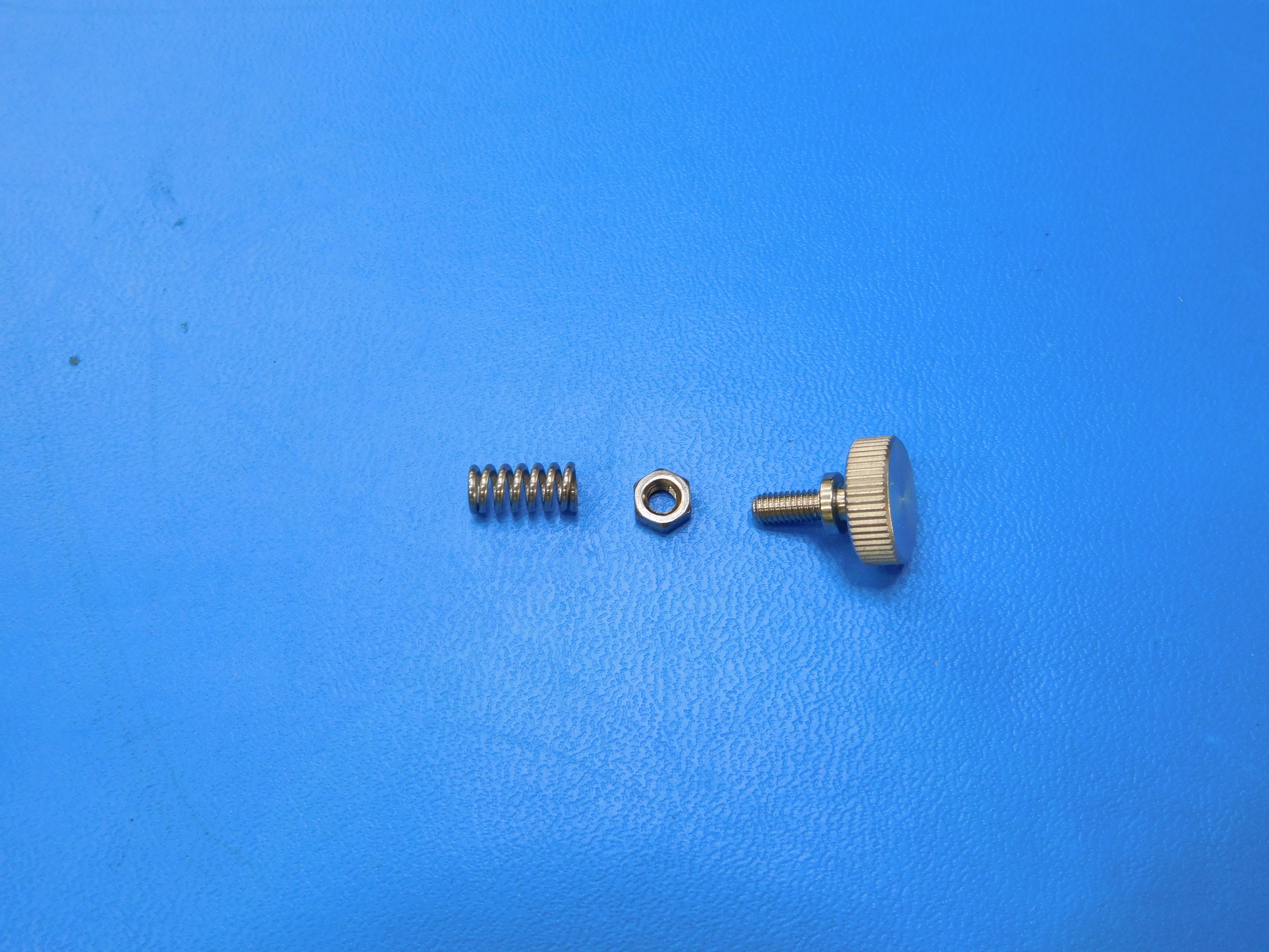
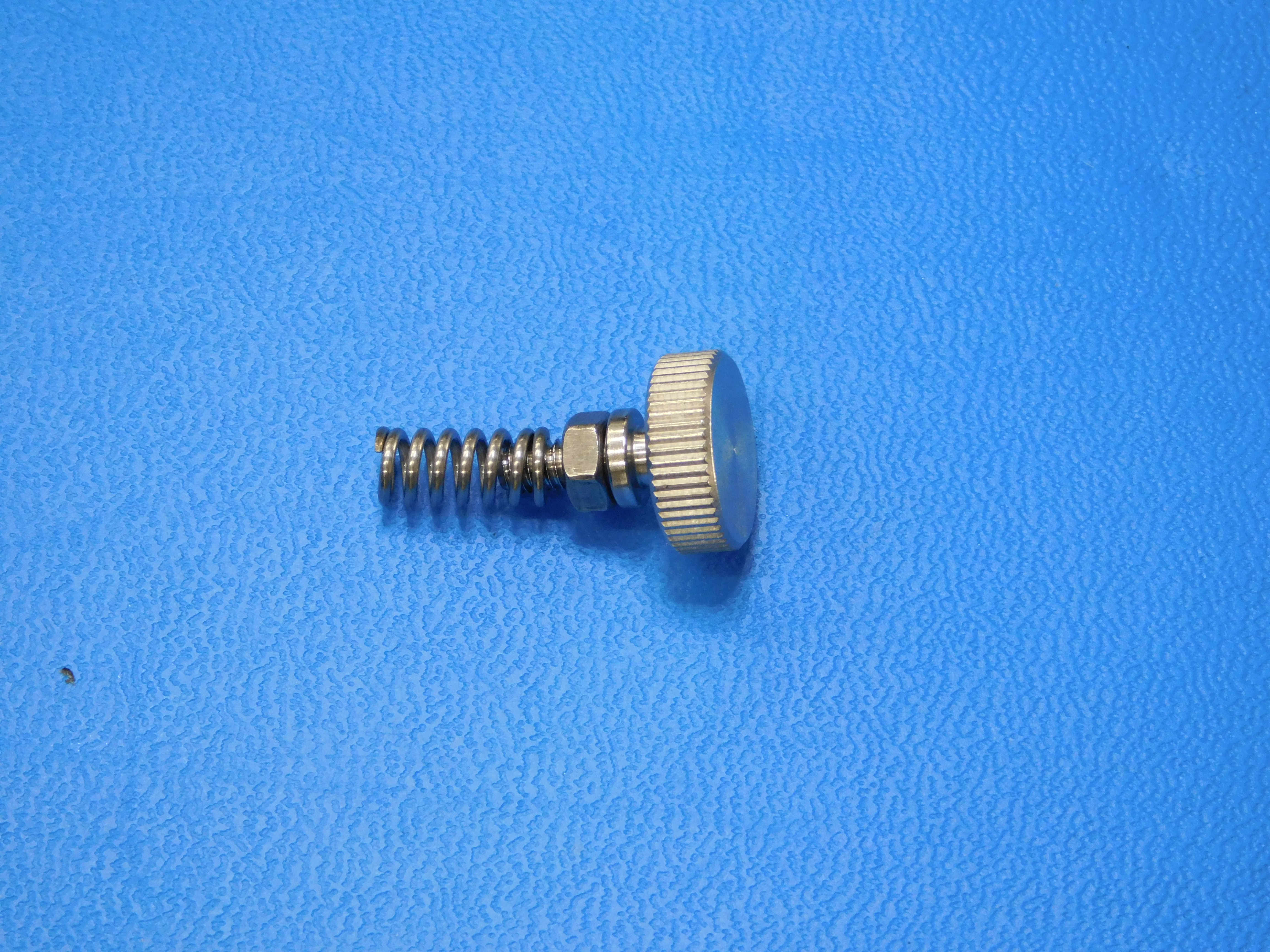
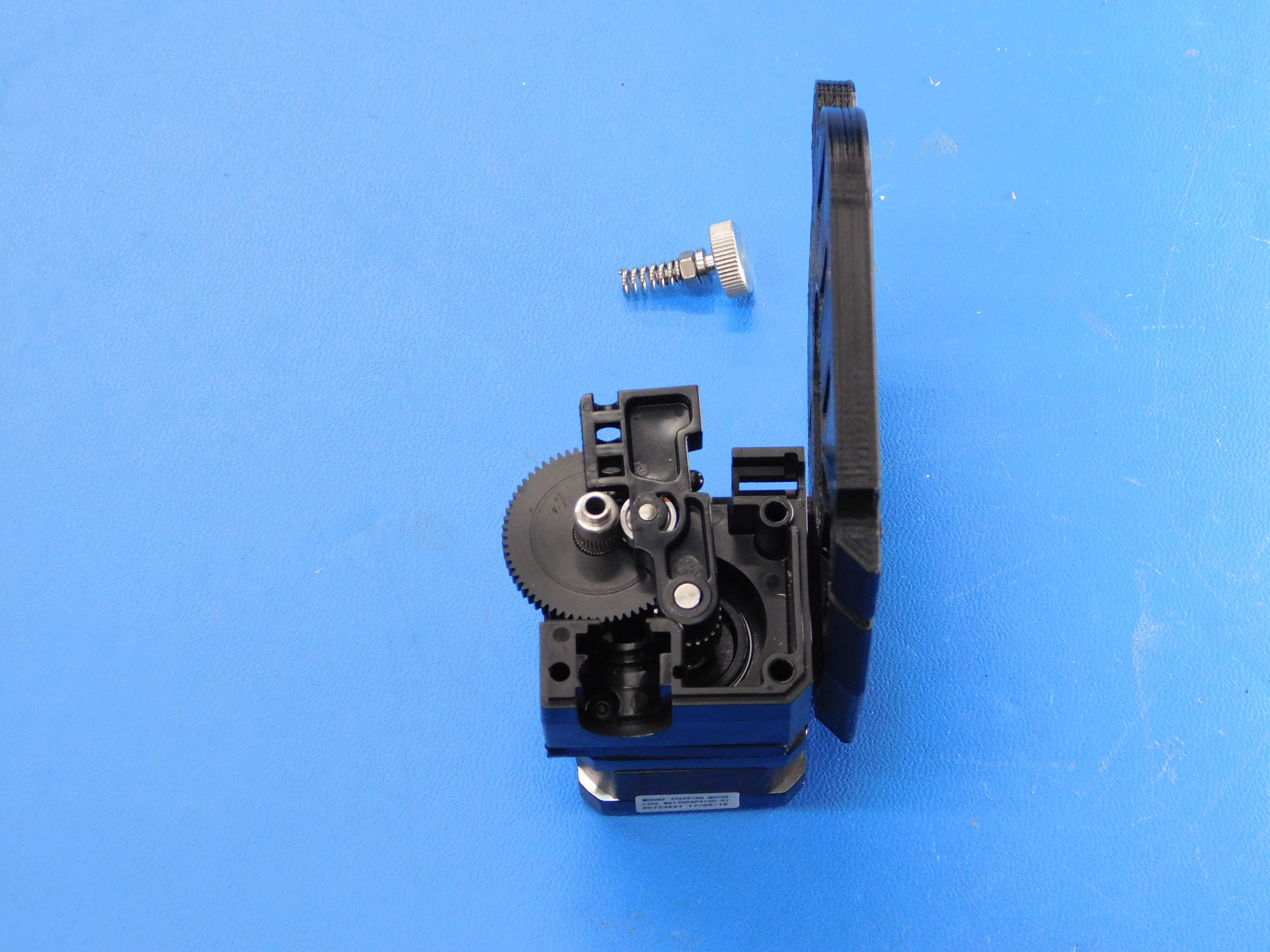
Assemble the idler bolt [HD-BT0197], idler nut [HD-NT0011], and spring [HD-MS0430] as shown.
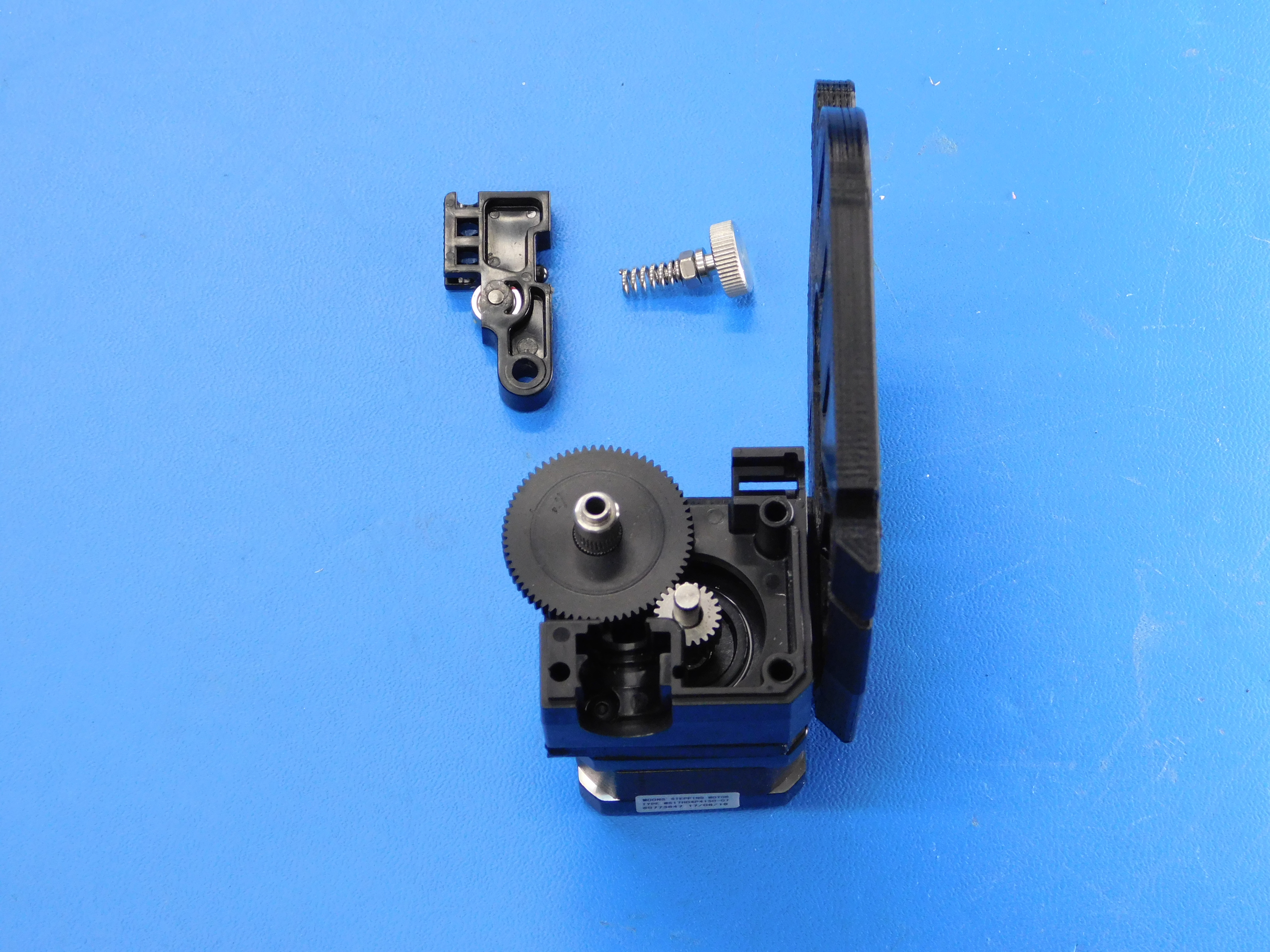
Install the idler [PP-FP0135] as shown.
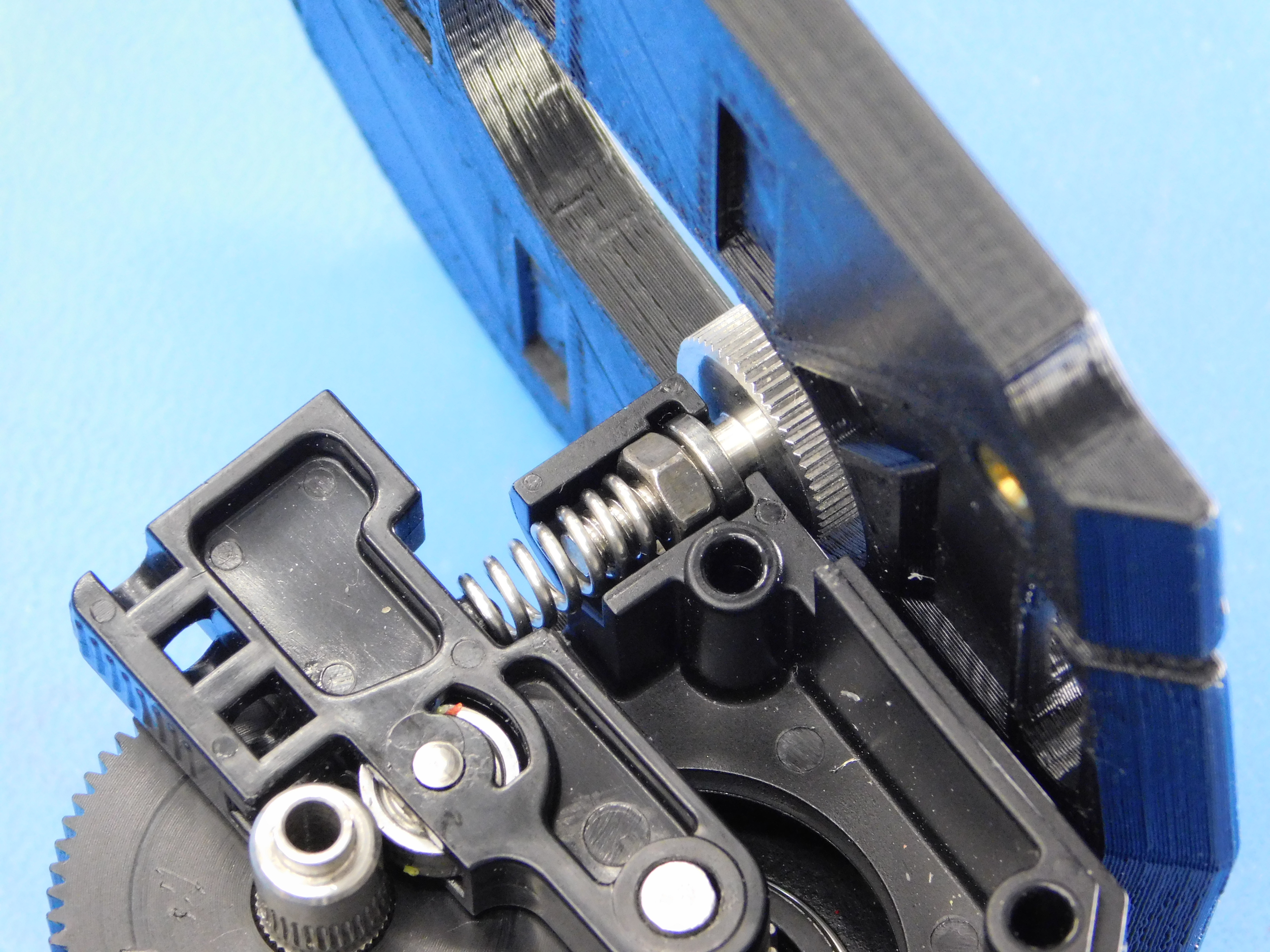
Install idler adjustment screw and spring assembly as shown.
Adjust the idler spring so the nut is in the middle.

Install the filament path insert [PP-FP0136] as shown.
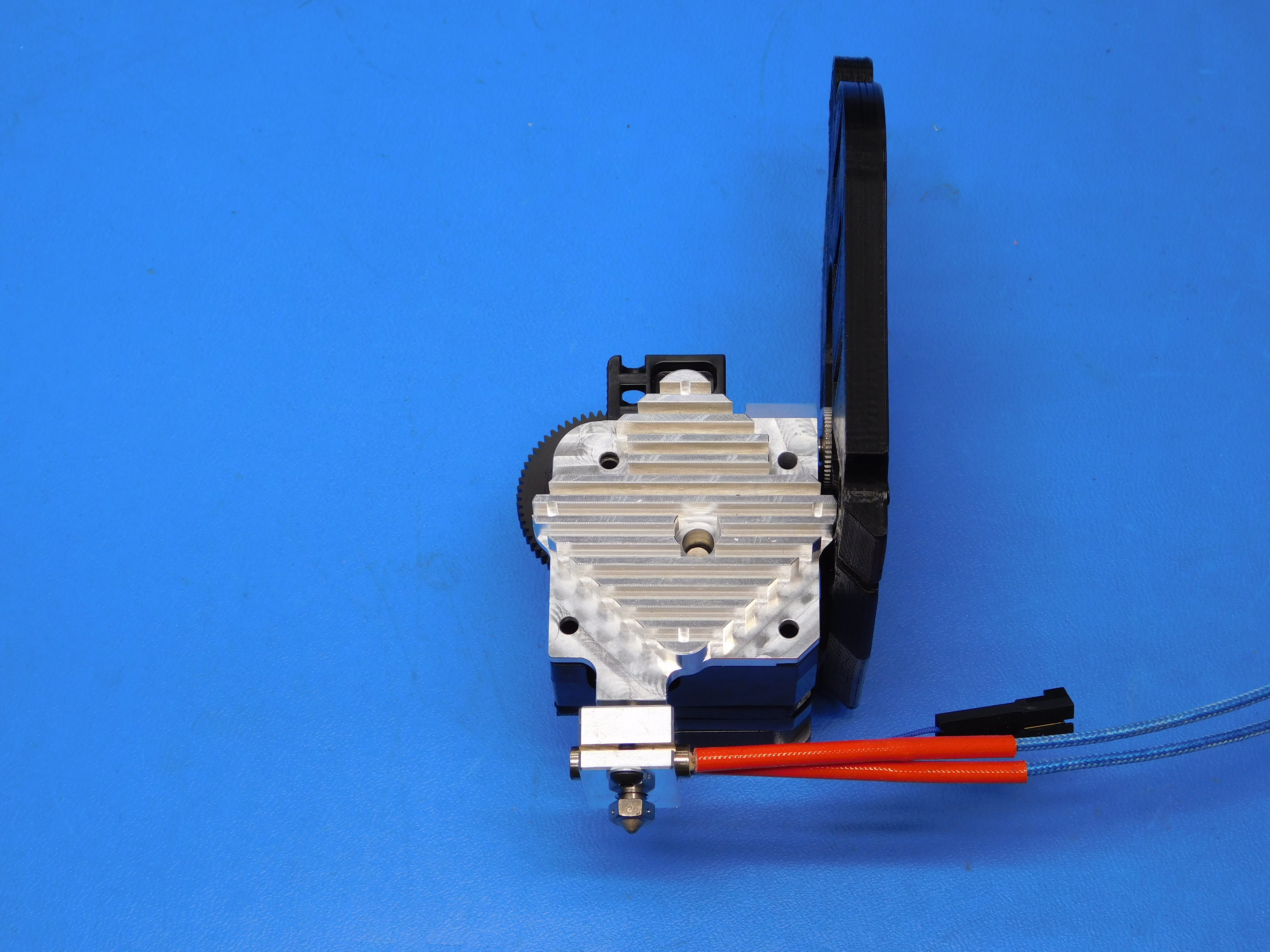
Place the Hotend Assembly (AS-HE0019) over the extruder assembly as shown.
Ensure the filament path insert stays in place and the hobbed shaft mates with the bearing in the heatsink smoothly.
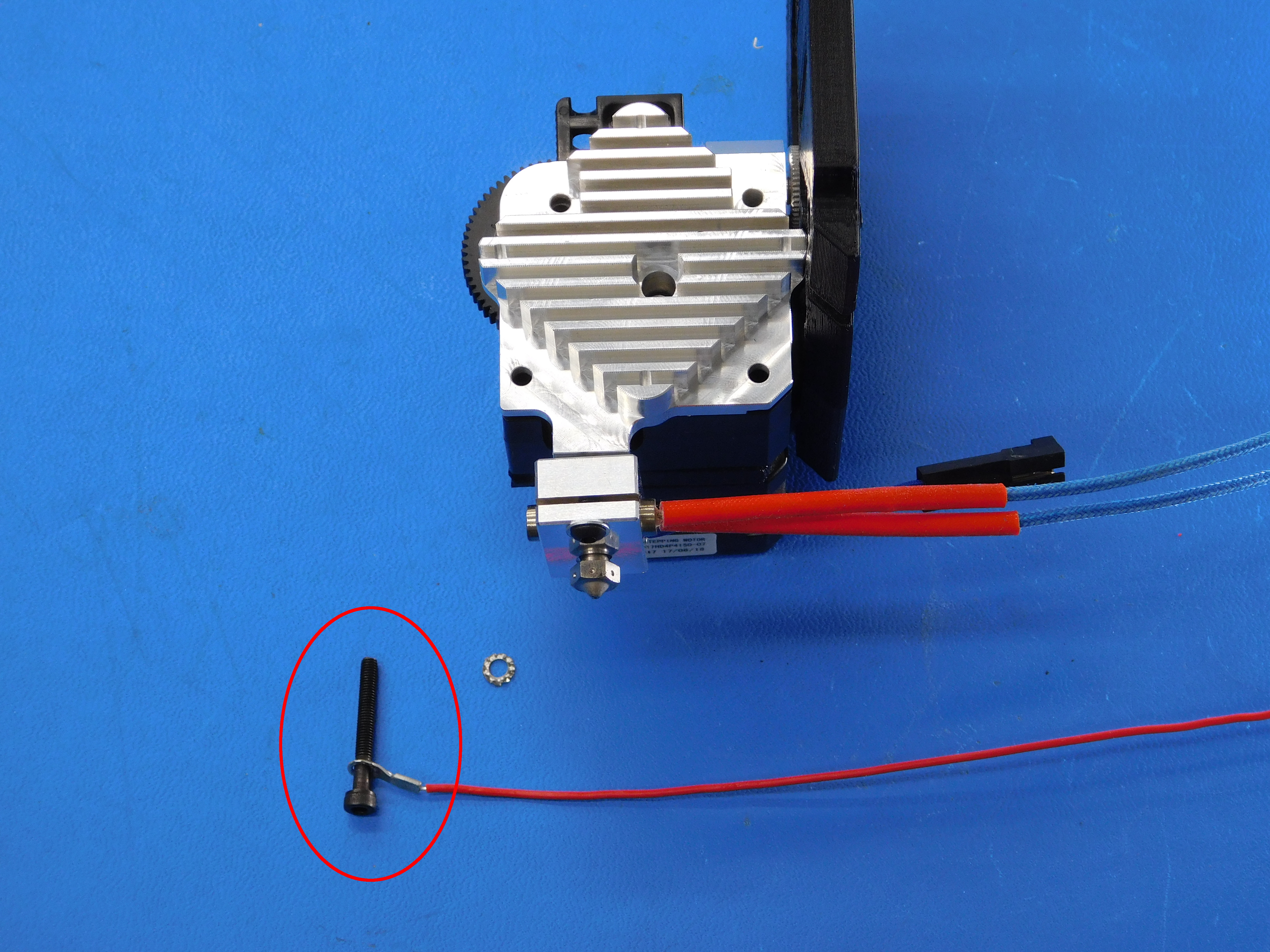
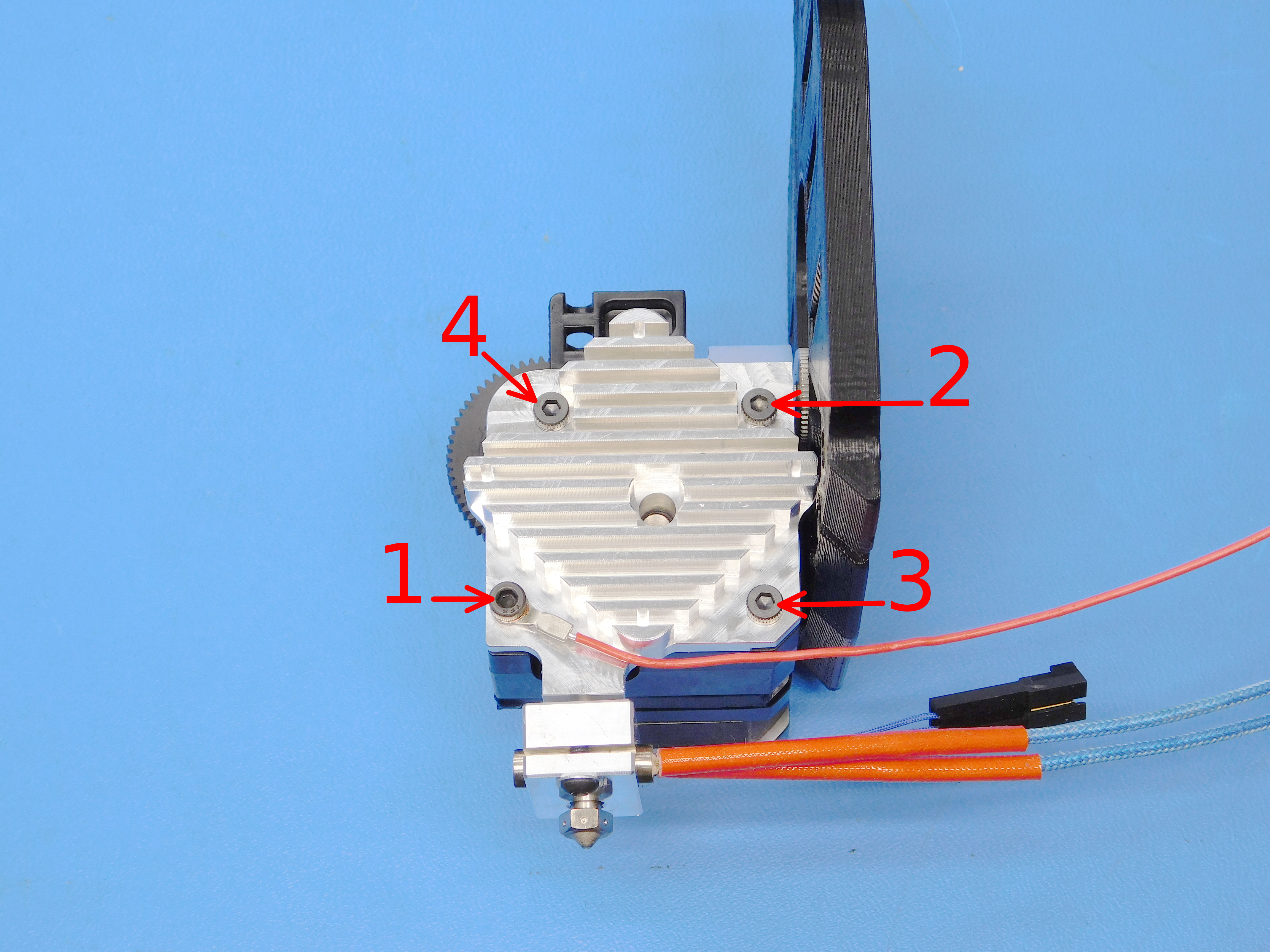
Locate the M3x25 SHCS (HD-BT0041) and insert it through the terminal ring on the Hotend Ground Wire (AS-CB0047).
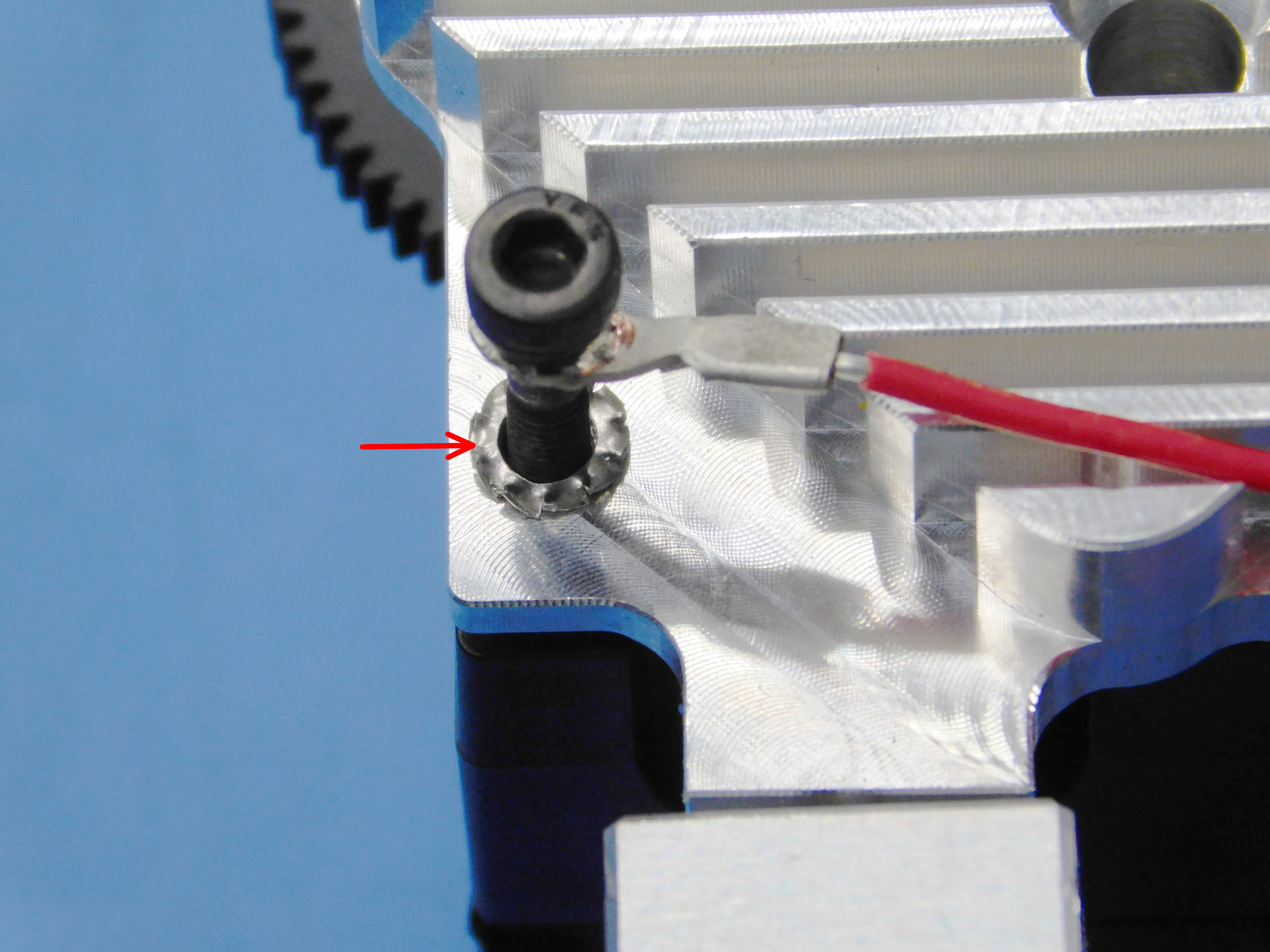
Install the External Tooth Lock Washer (HD-WA0035) between the terminal ring and the heatsink when installing the fastener to the lower left mounting hole of the Hotend Assembly.
Place three (3) M3x35 SHCS (HD-BT0043) in the remaining mounting holes.
Torque the four mounting screws in the following order to 3 IN-LBS:
1. Lower Left
2. Upper Right
3. Lower Right
4. Upper Left
See image at right.
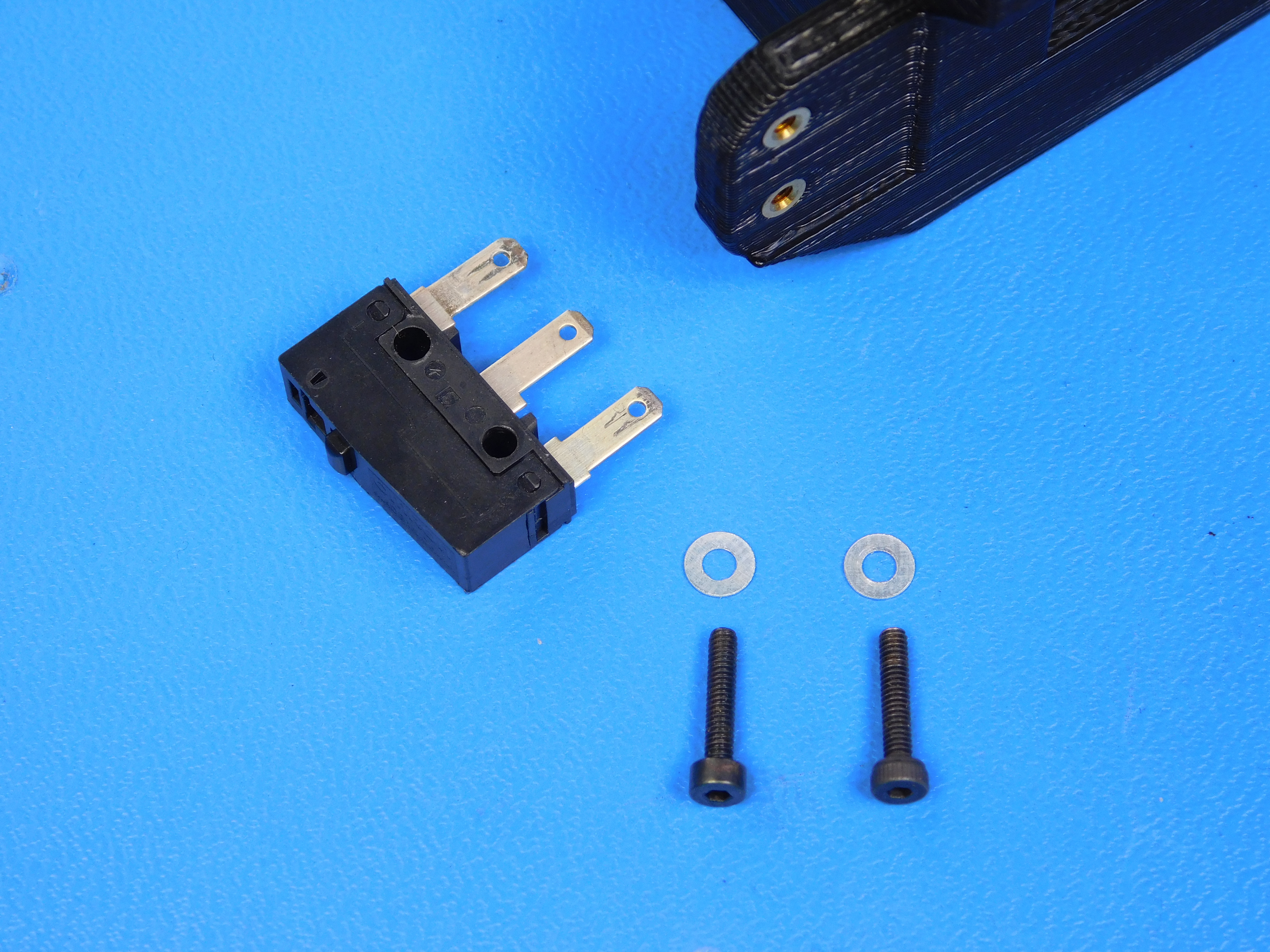
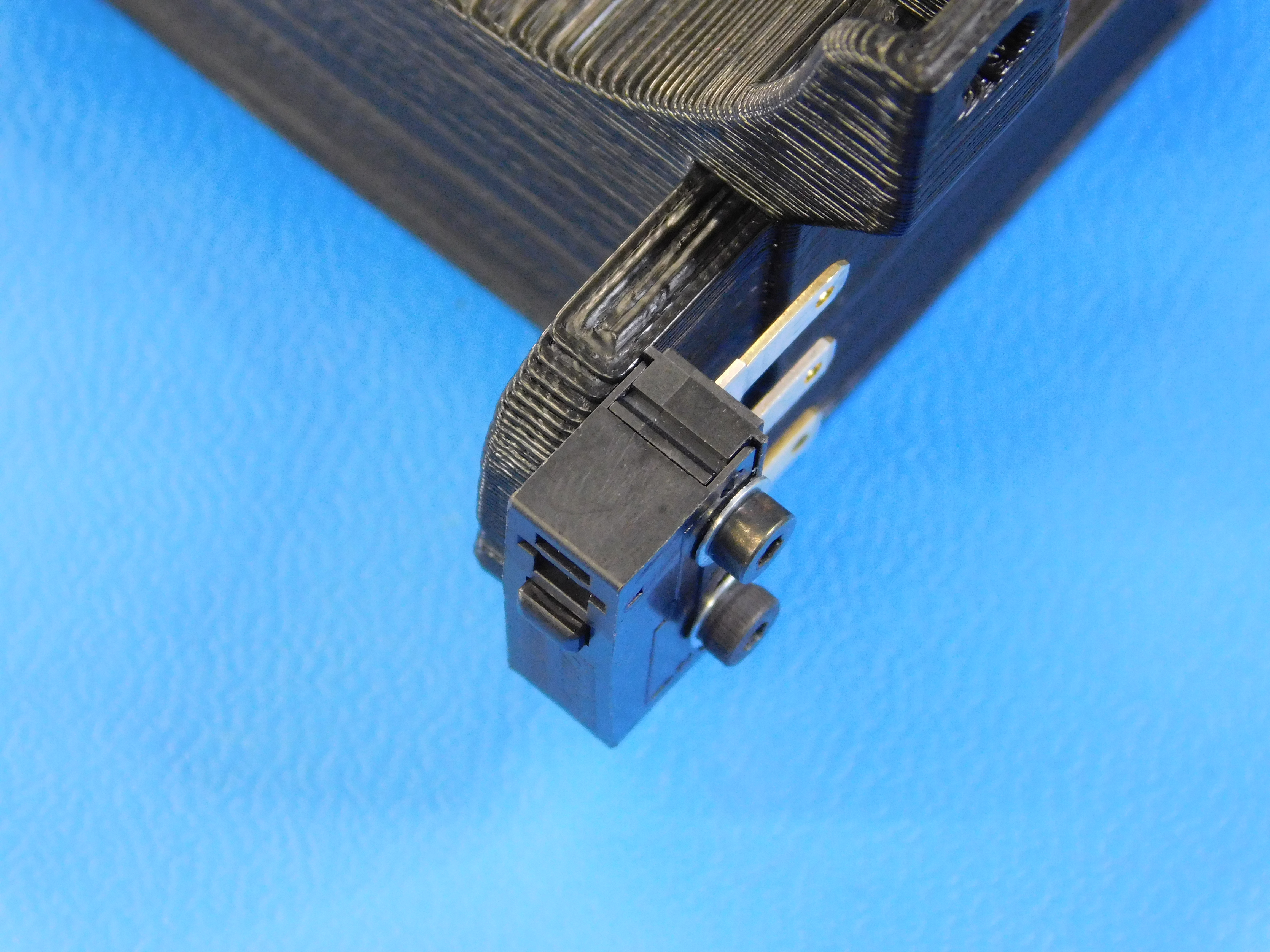
Fasten the endstop [EL-SW0022] to the fan duct as shown using two M2 x 10 SHCS [HD-BT0107] and two M2 washers [HD-WA0012].
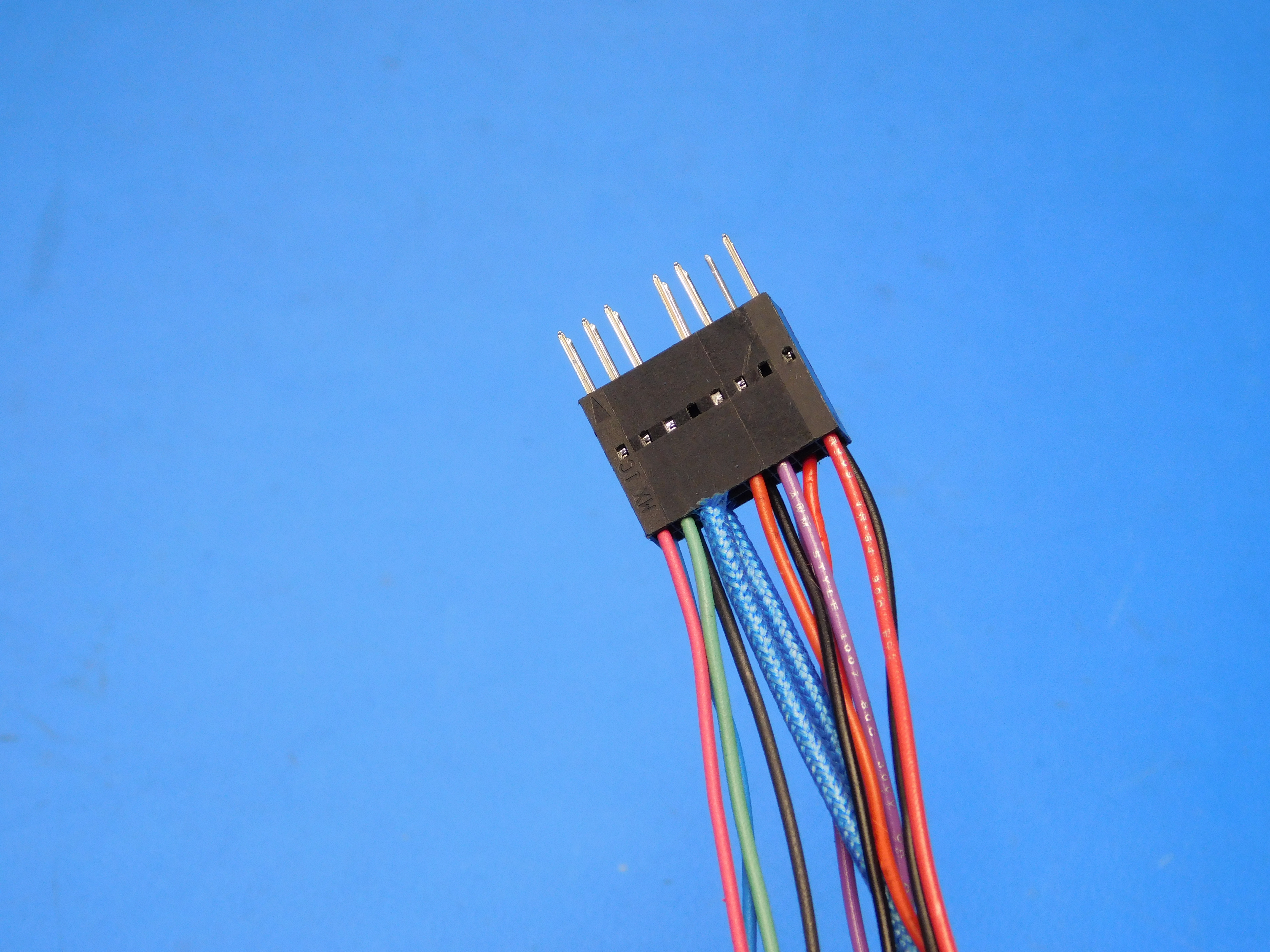
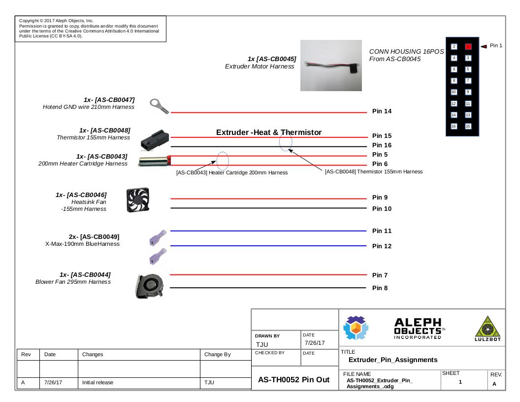
Refer to the Pin-Out Diagram for Pin Locations
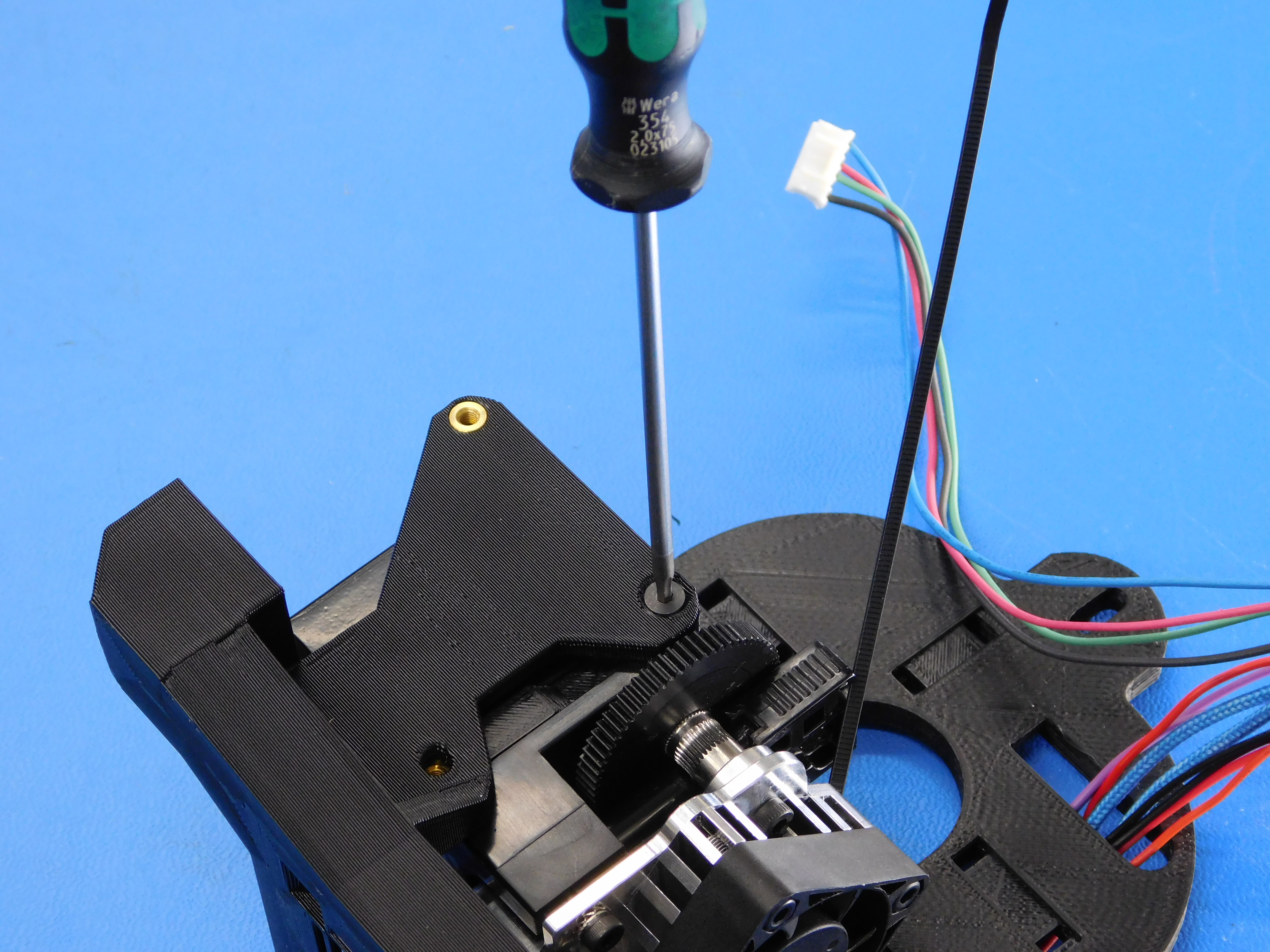
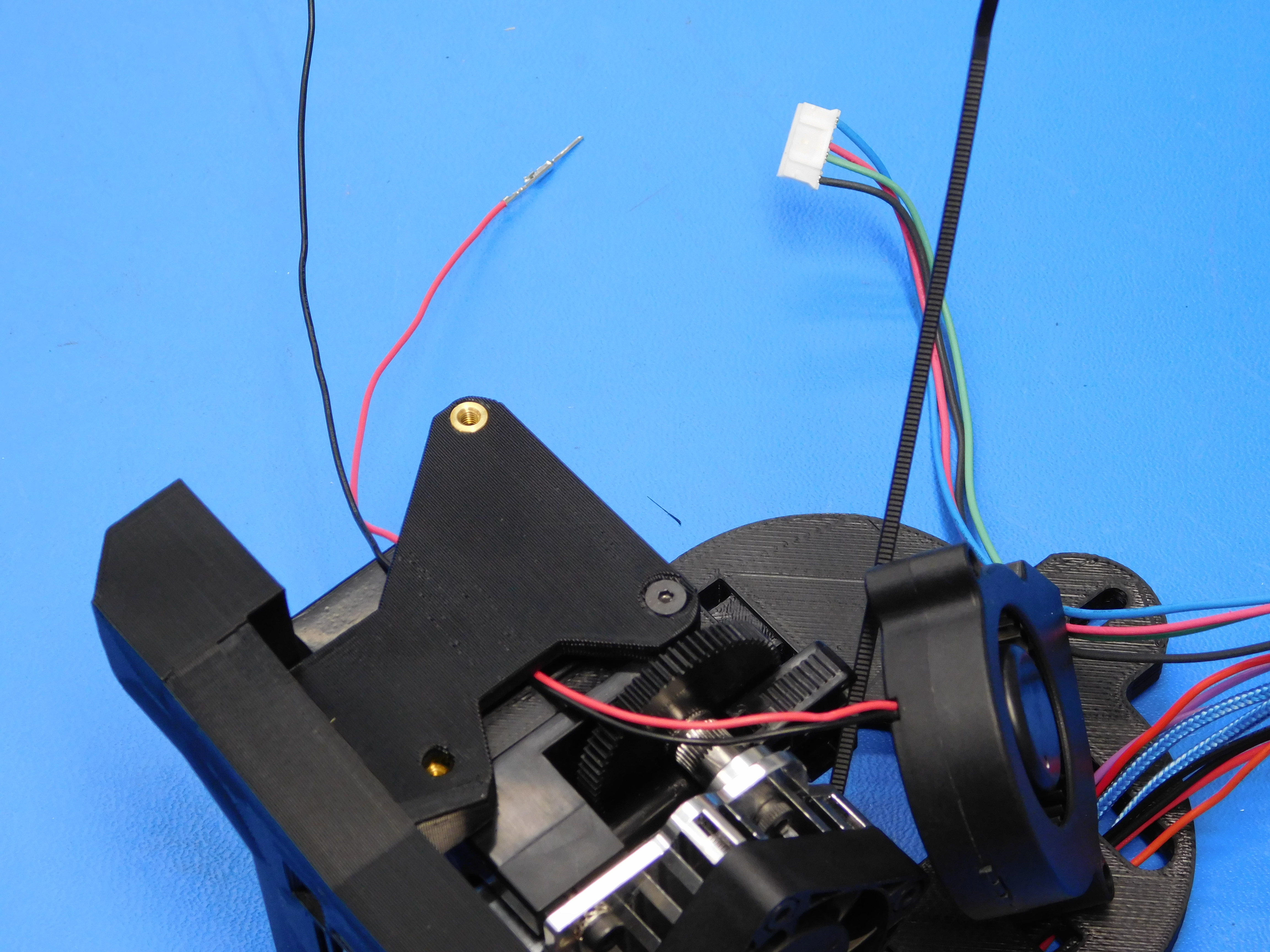
Route the Hotend Ground Wire as shown and insert the Pin to position 14 of the Extruder Motor Extension (AS-CB0045).
Route the Heater Cartridge leads as shown and insert the pins to positions 5 & 6.
Place Heatsink Fan [AS-CB0046] as shown and secure using 4x M3x12 SHCS (HD-BT0039), note the orientation of the fan wires.
Be sure the fan is in the correct orientation. The label should not be visible and the screws should sit flush in the fan housing.
Route the Heatsink Fan wires as pictured and insert the pins to positions 9 & 10 according to the diagram.
Place the purple endstop wires in place as pictured and insert the pins to positions 11 & 12 according to the diagram.
Connect Thermistor Harness, route as pictured, and insert the pins into positions 15 & 16 according to the diagram.
Install the Zip-Tie near the heatsink fan as shown.

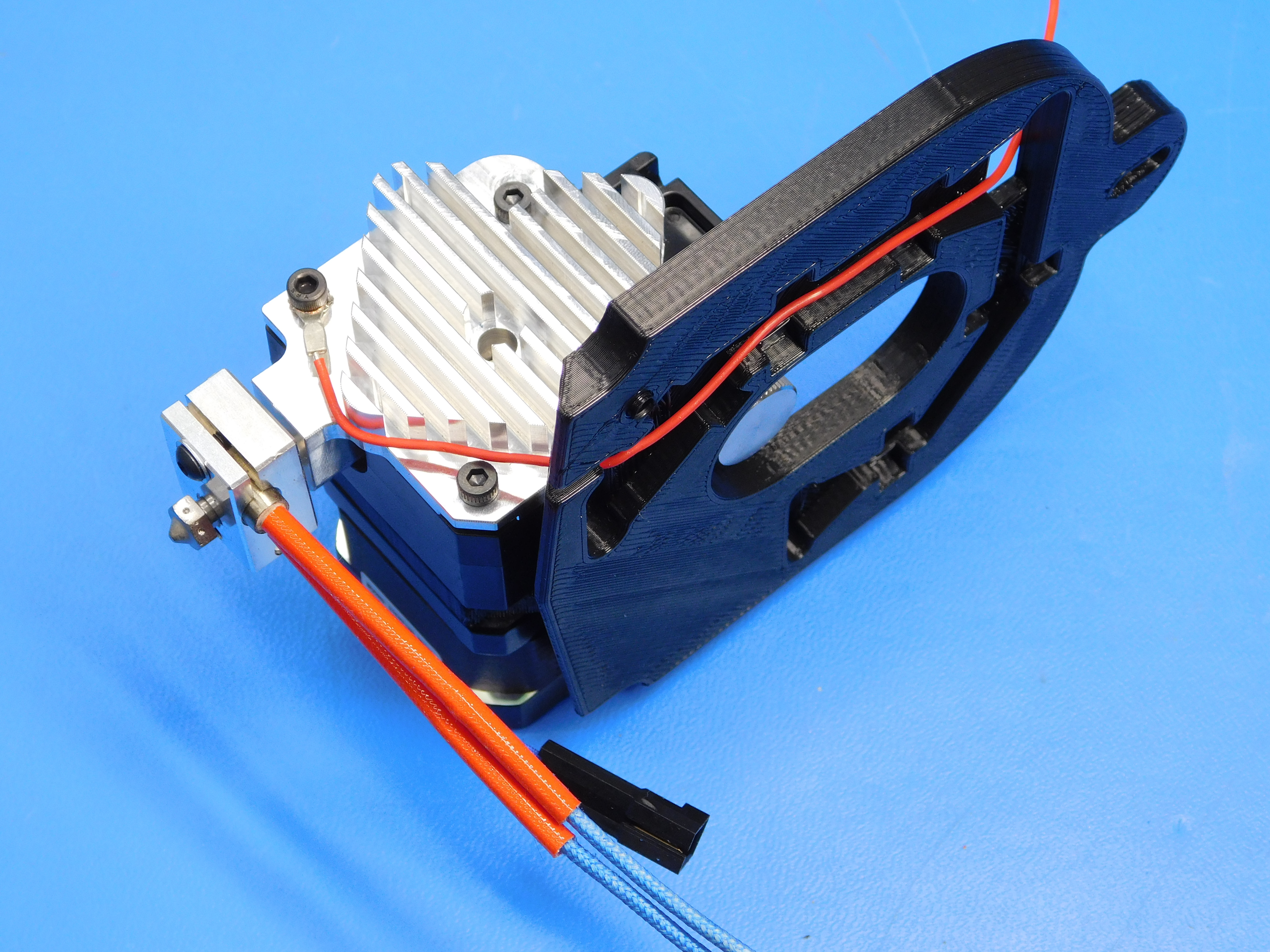
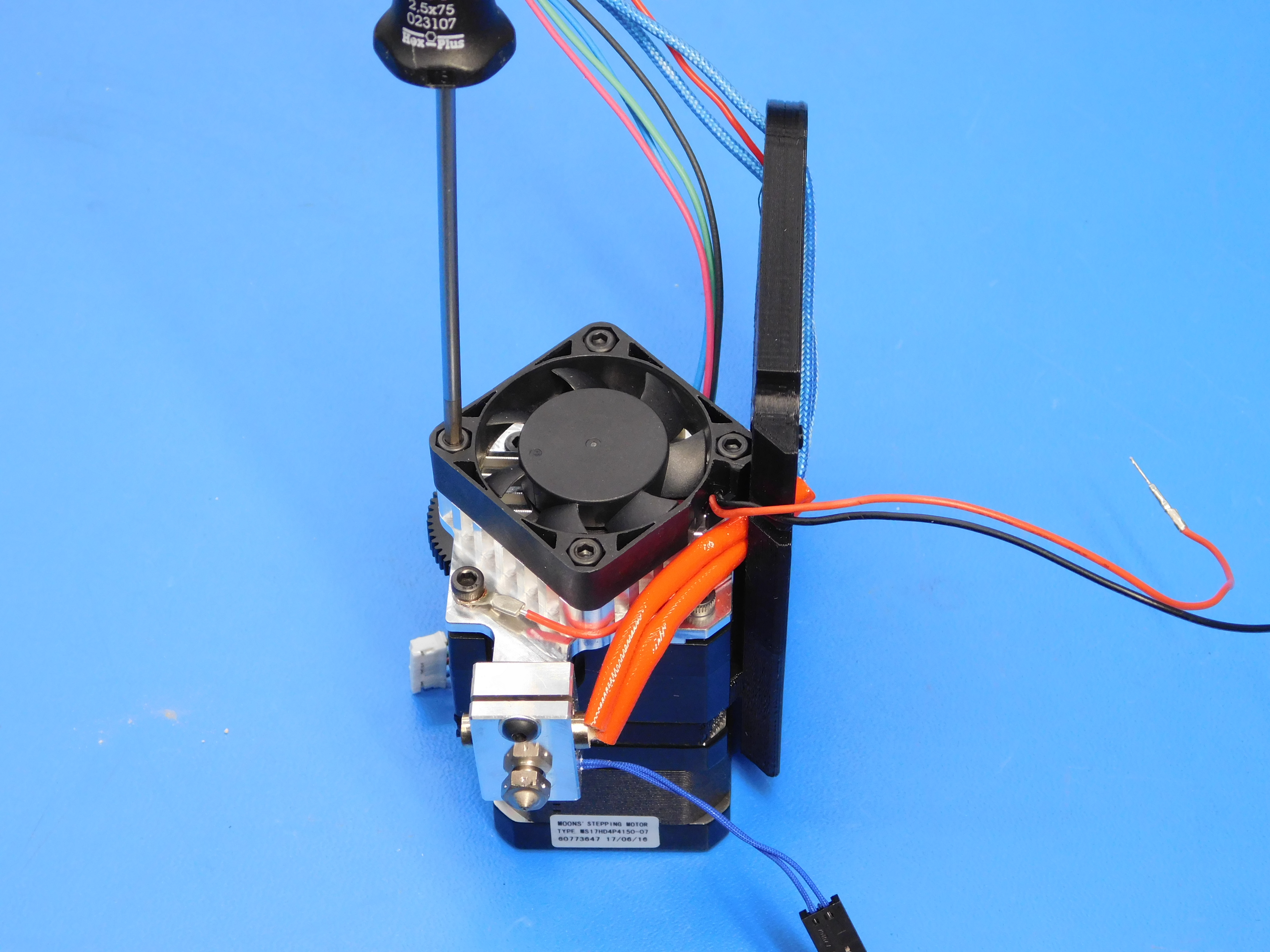


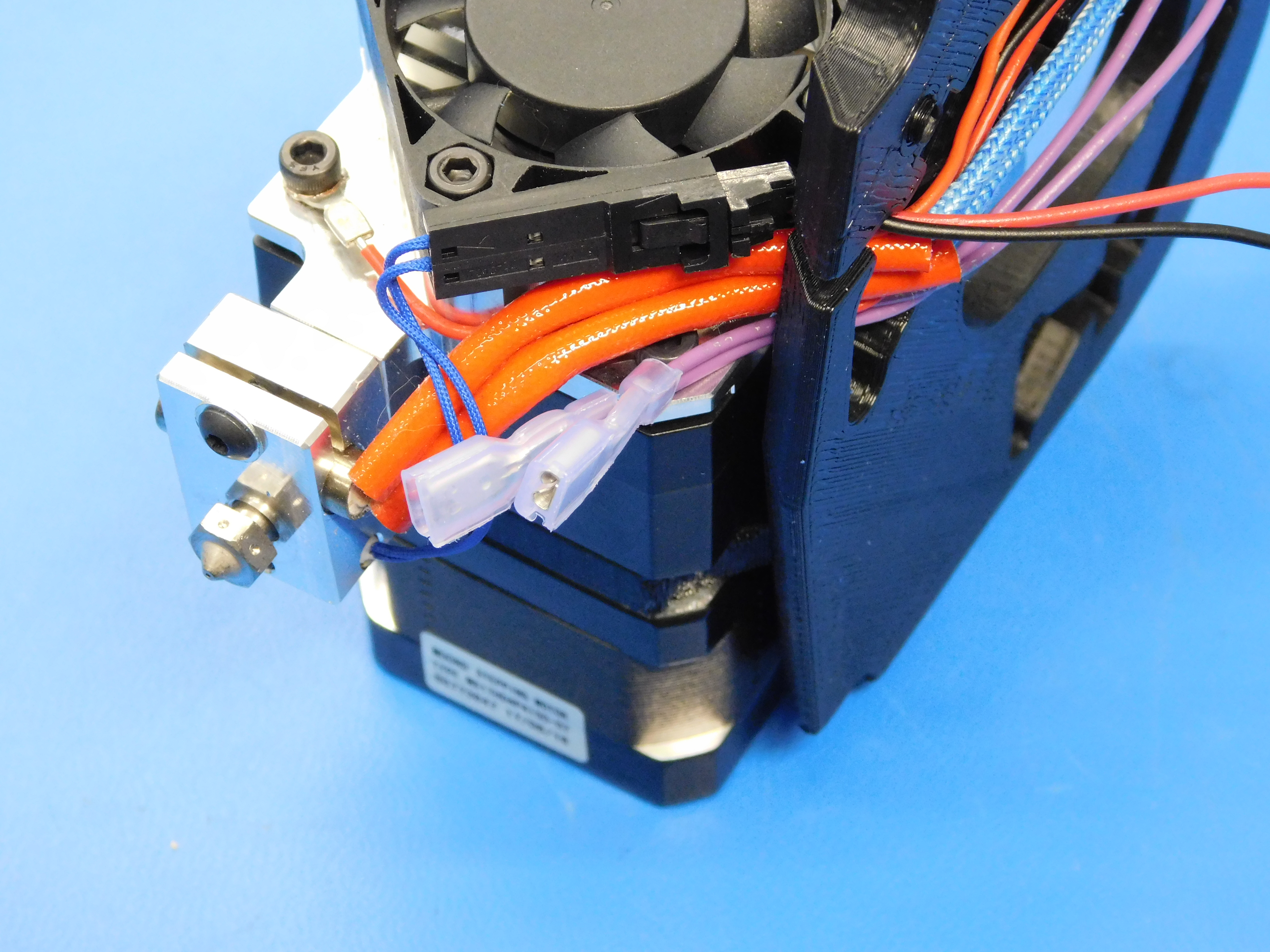
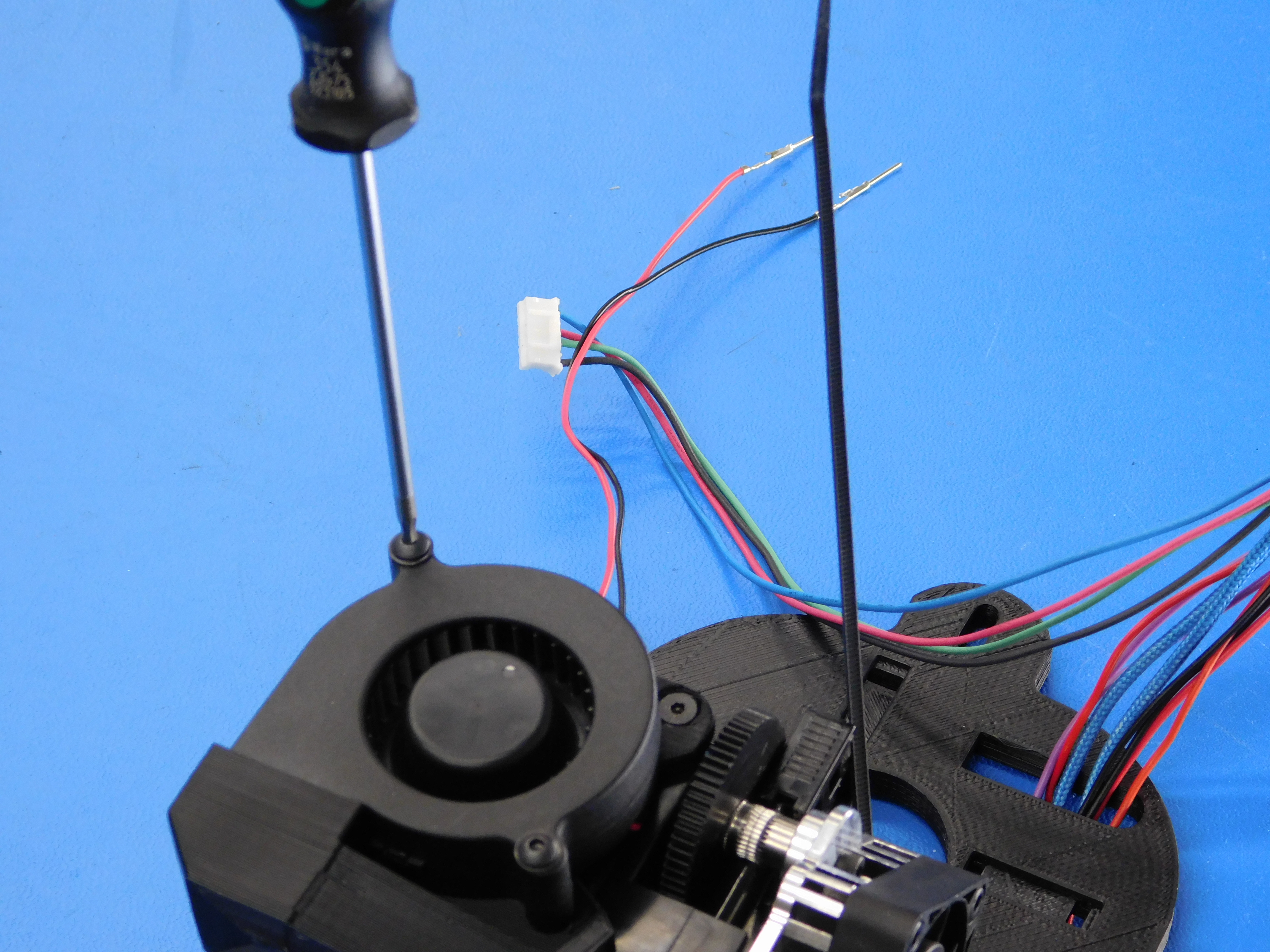
Install the Fan Duct (PP-IS0038) to the assembly as shown.
Secure using one M3x5 SHCS (HD-BT0044) with Washer (HD-WA0038) on the right and one M3x6 FHCS (HD-BT0128) on the left.
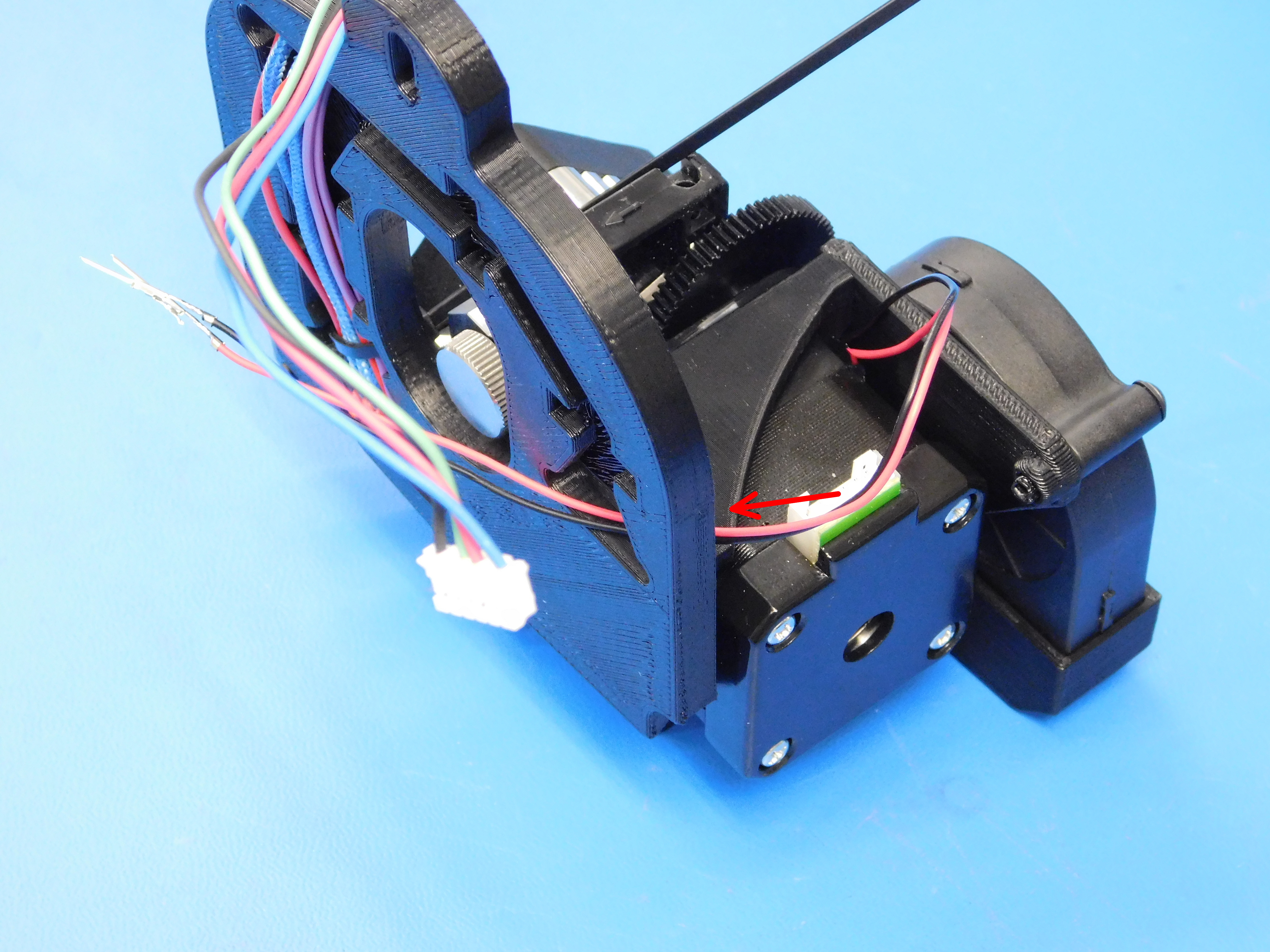
On the back, connect the purple connectors to the endstop switch as pictured. The middle terminal should be open.

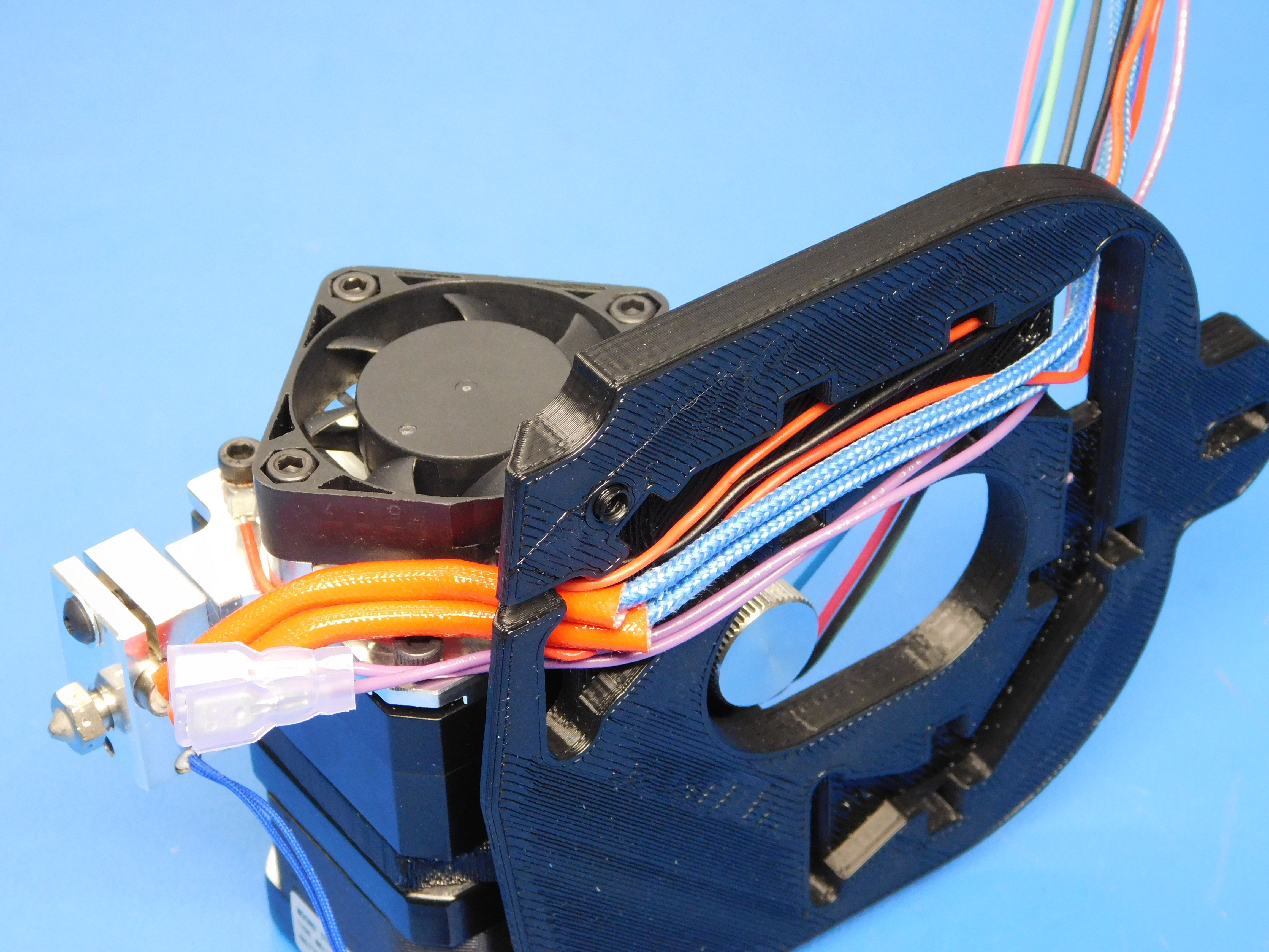
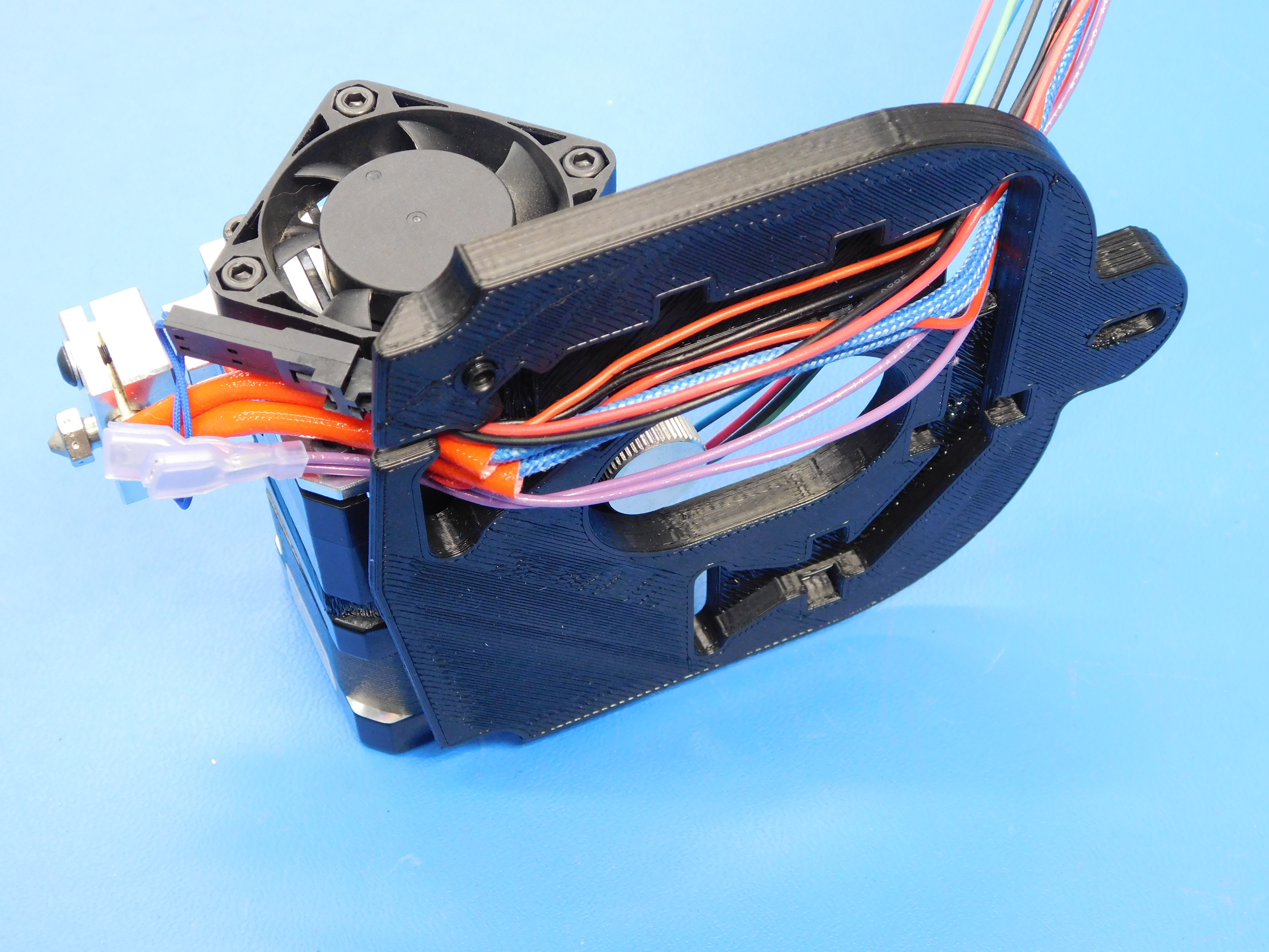
Pass the end of the blower fan harness through the pathway beneath the fan duct as shown.
Using one M3 x 20 BHCS [HD-BT0171], one M3 x 25 BHCS [HD-BT0202], and two M3 washers [HD-WA0038] install the blower fan [AS-CB0044] as shown. The shorter of the two fasteners goes on the top left of the blower fan.
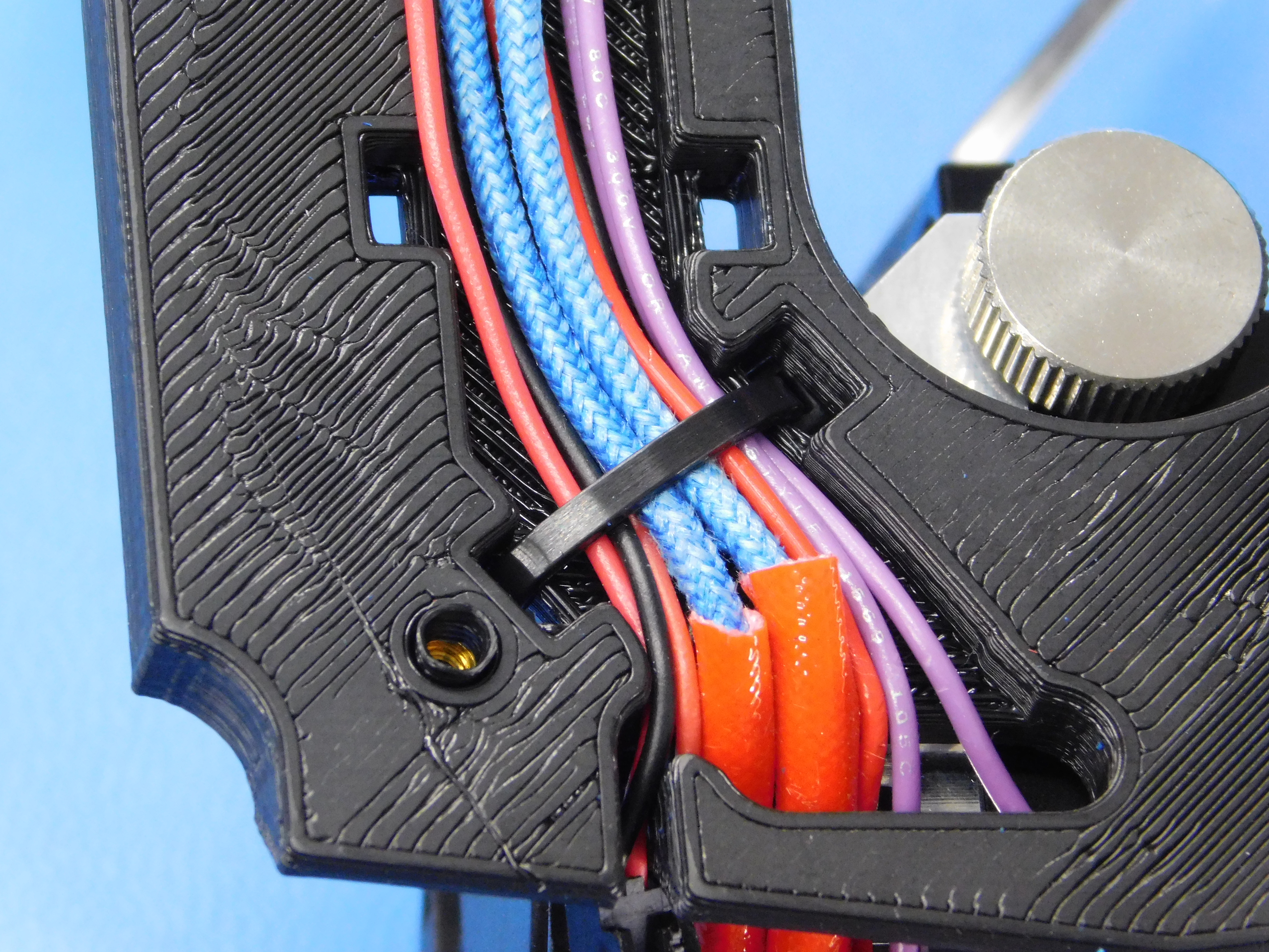
Continue routing the Blower Fan Harness as shown and insert the pins to positions 7 & 8 as shown.
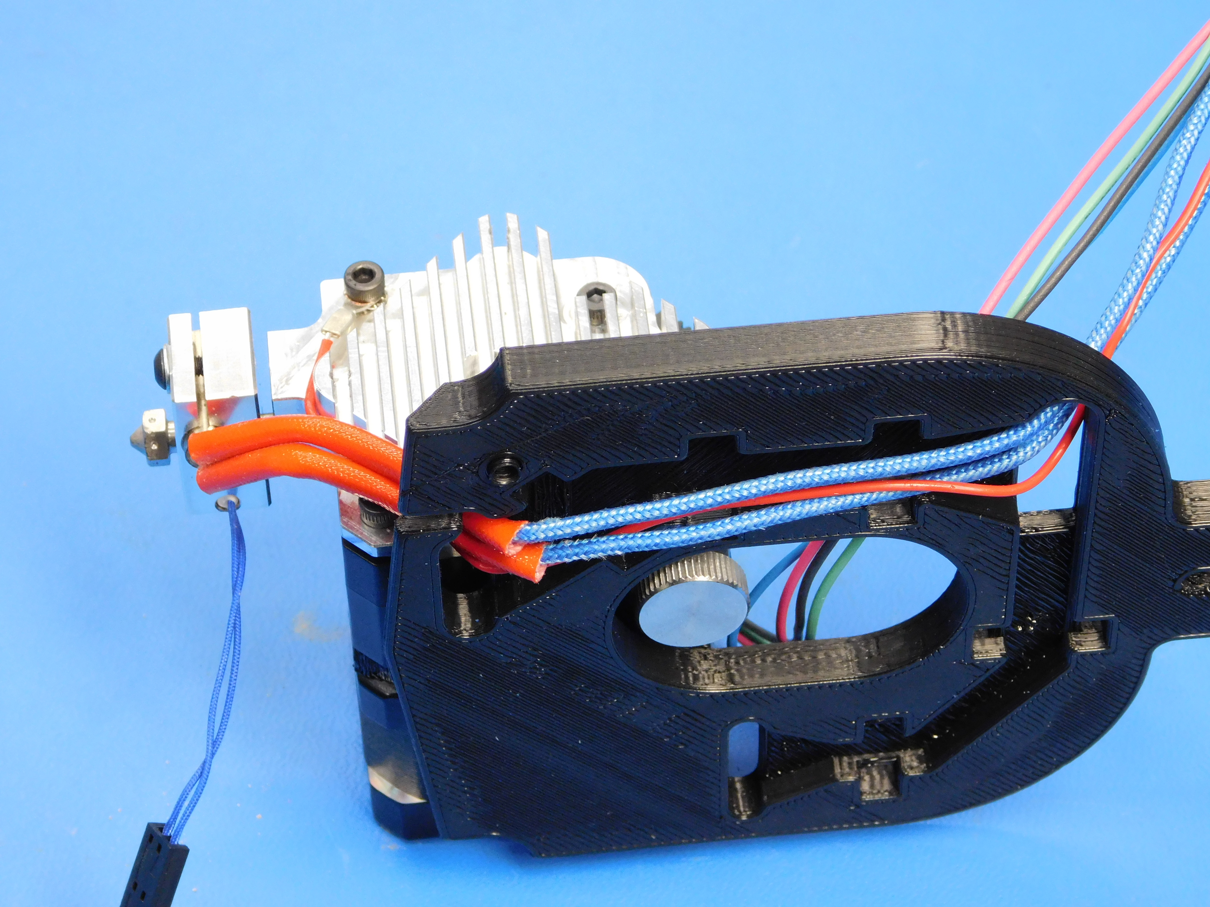
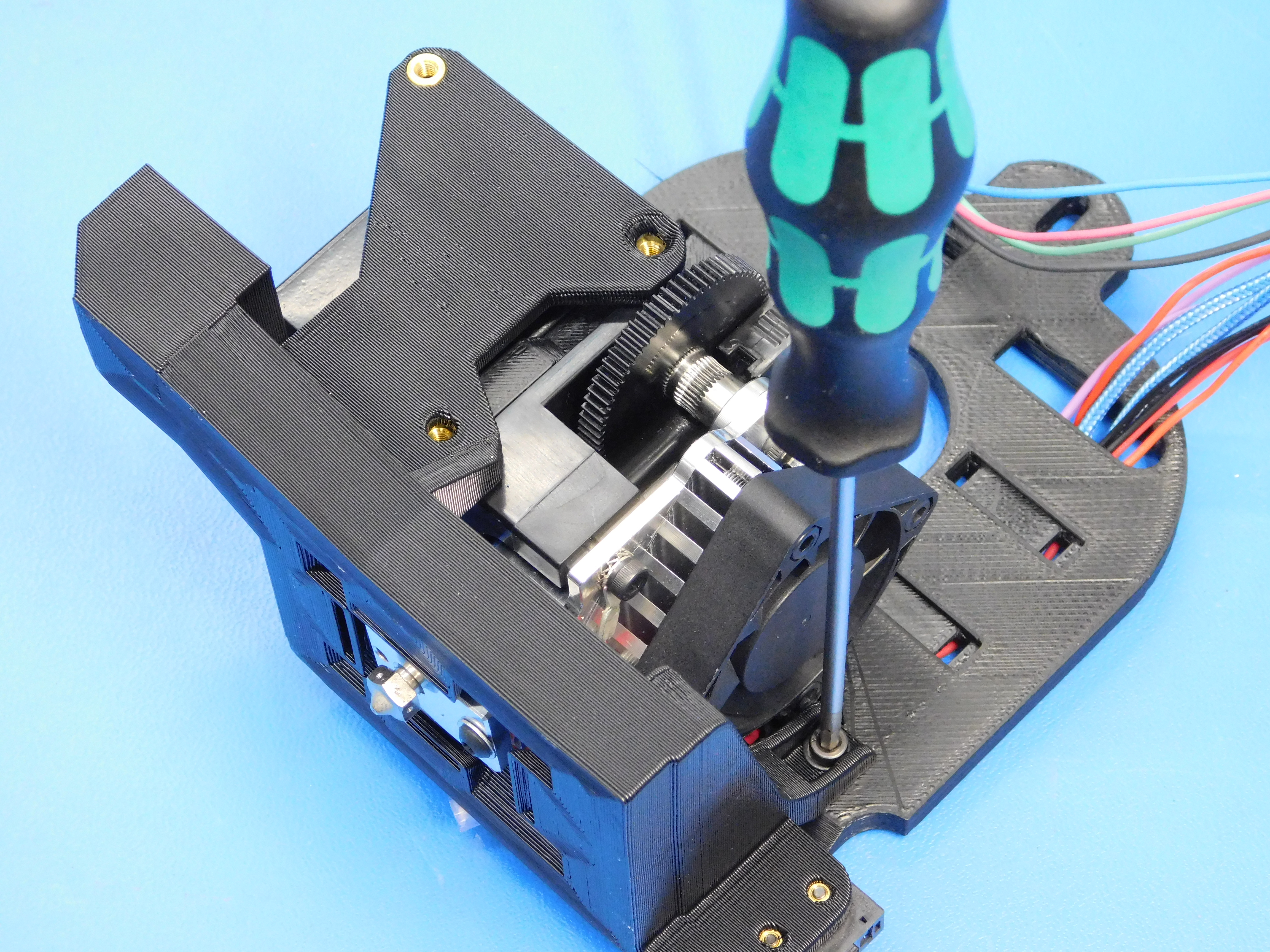
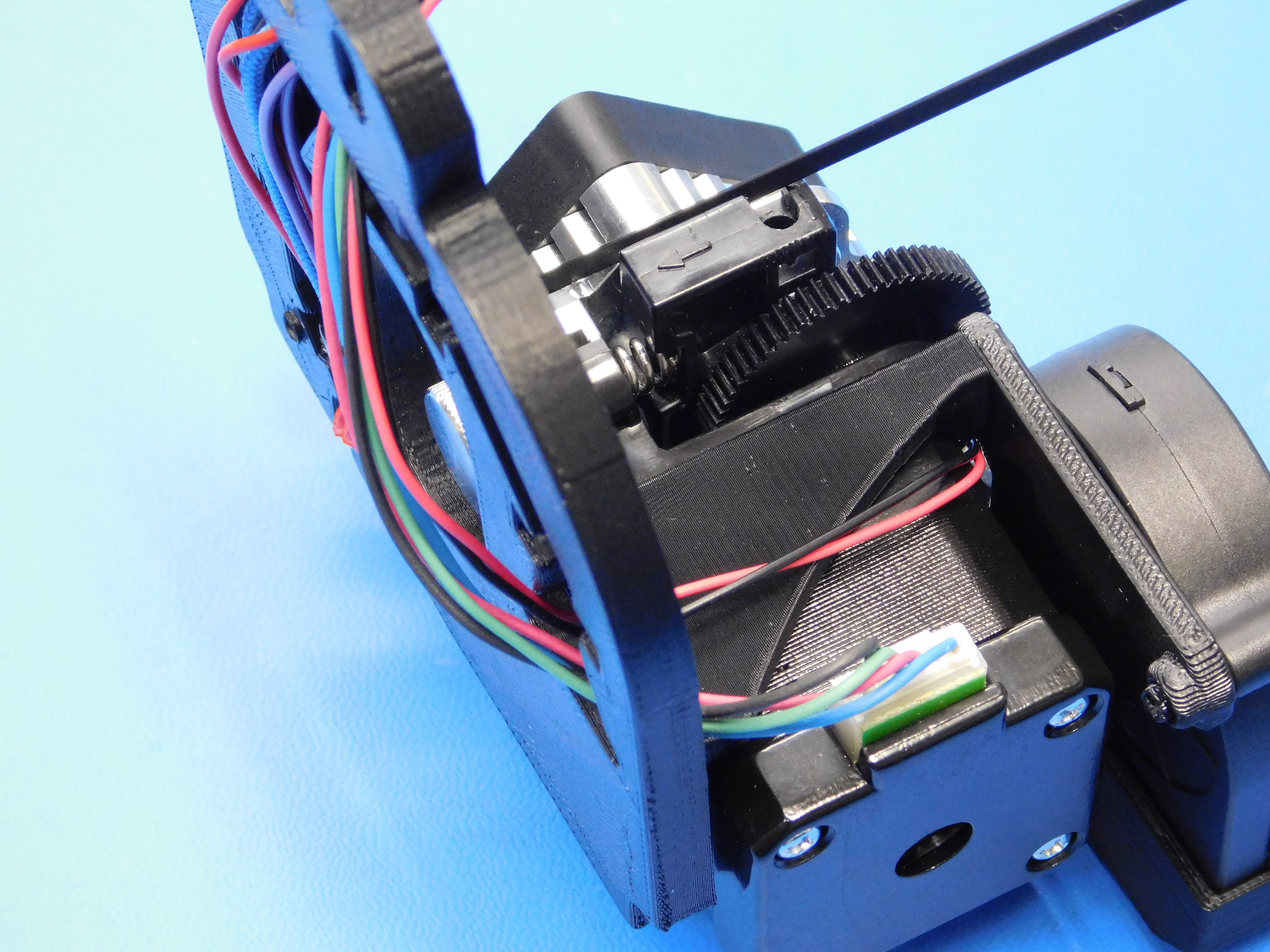
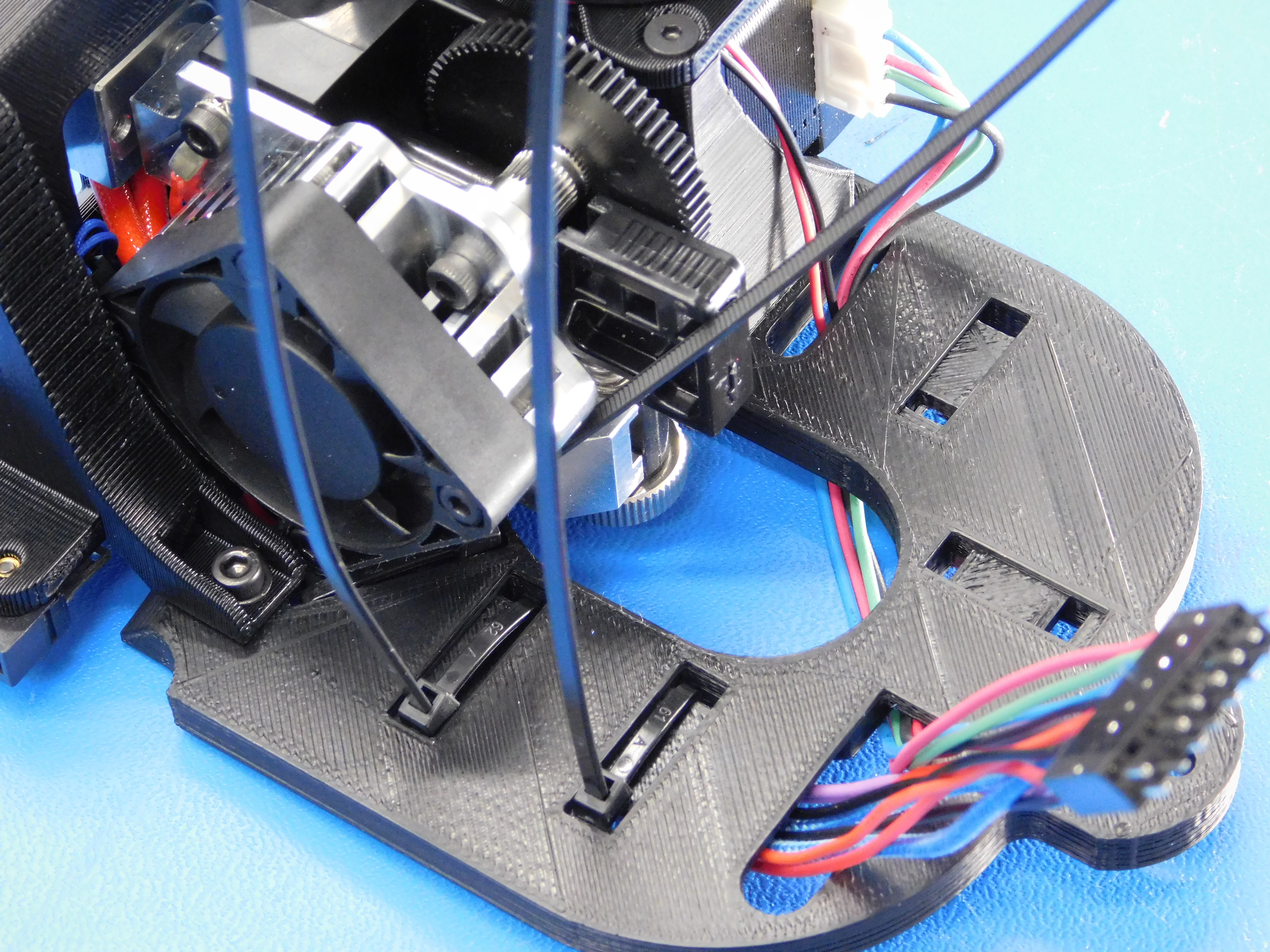
Route the Motor Harness through the extruder mount as shown and connect it to the motor.

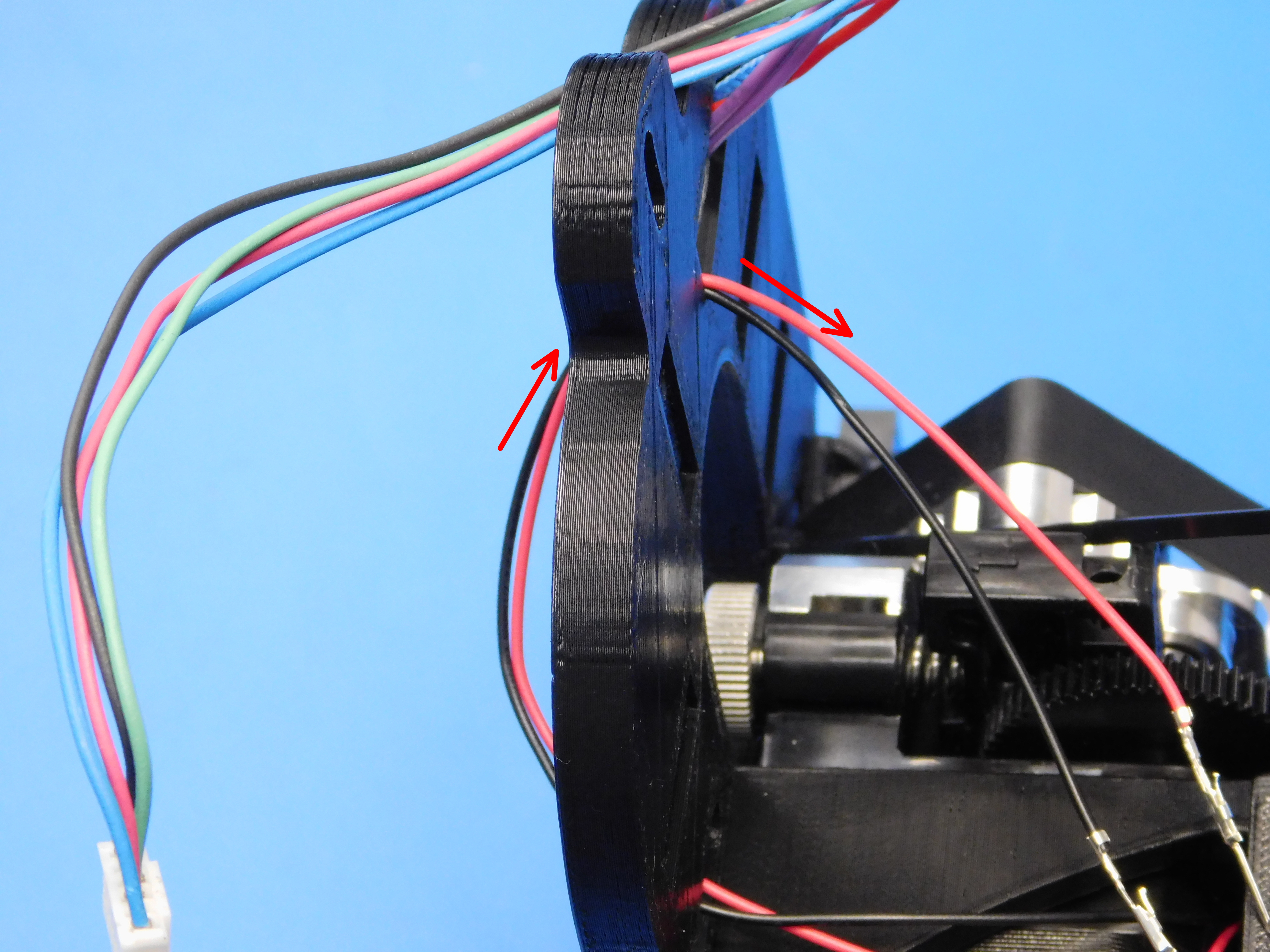
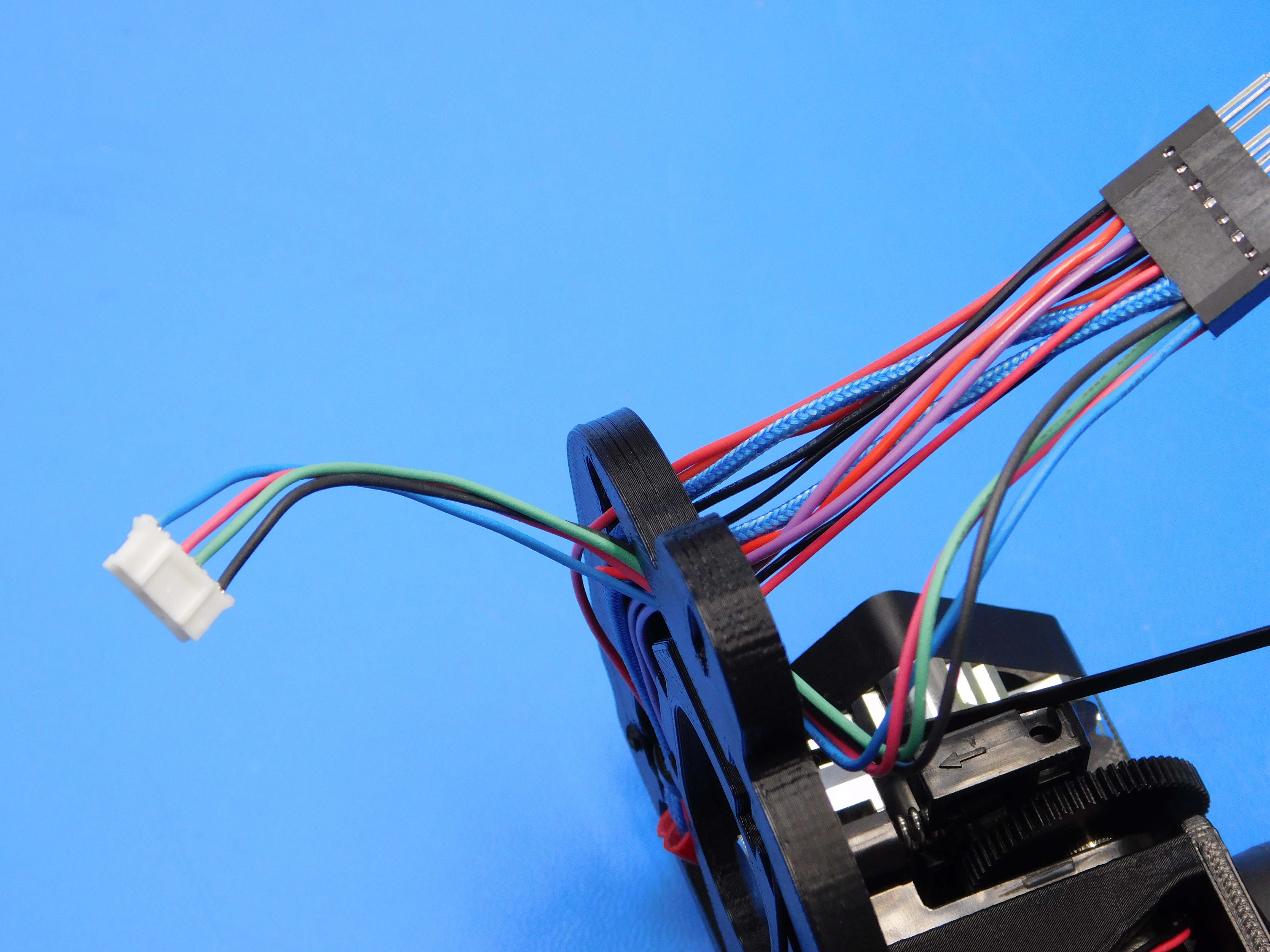
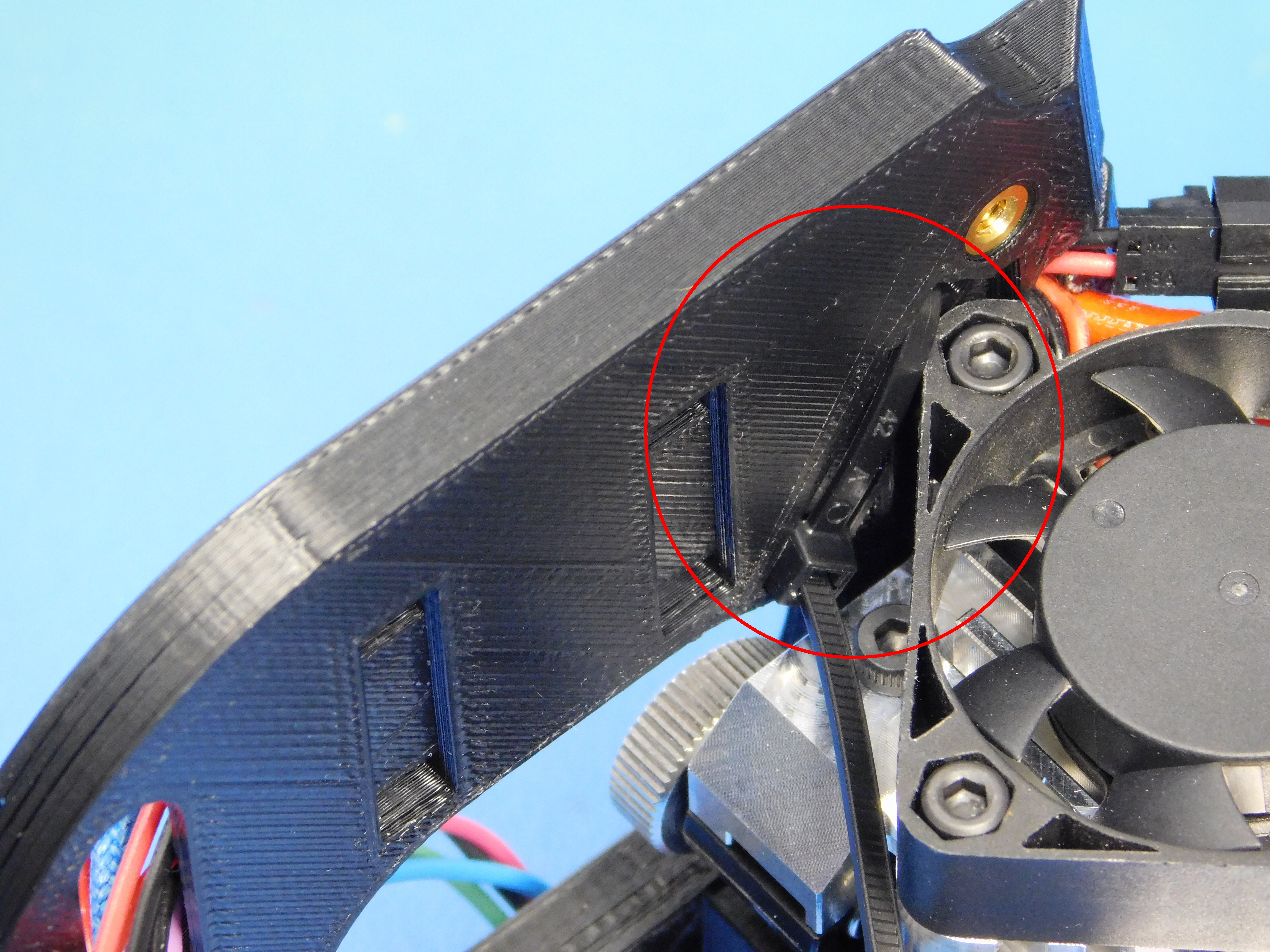
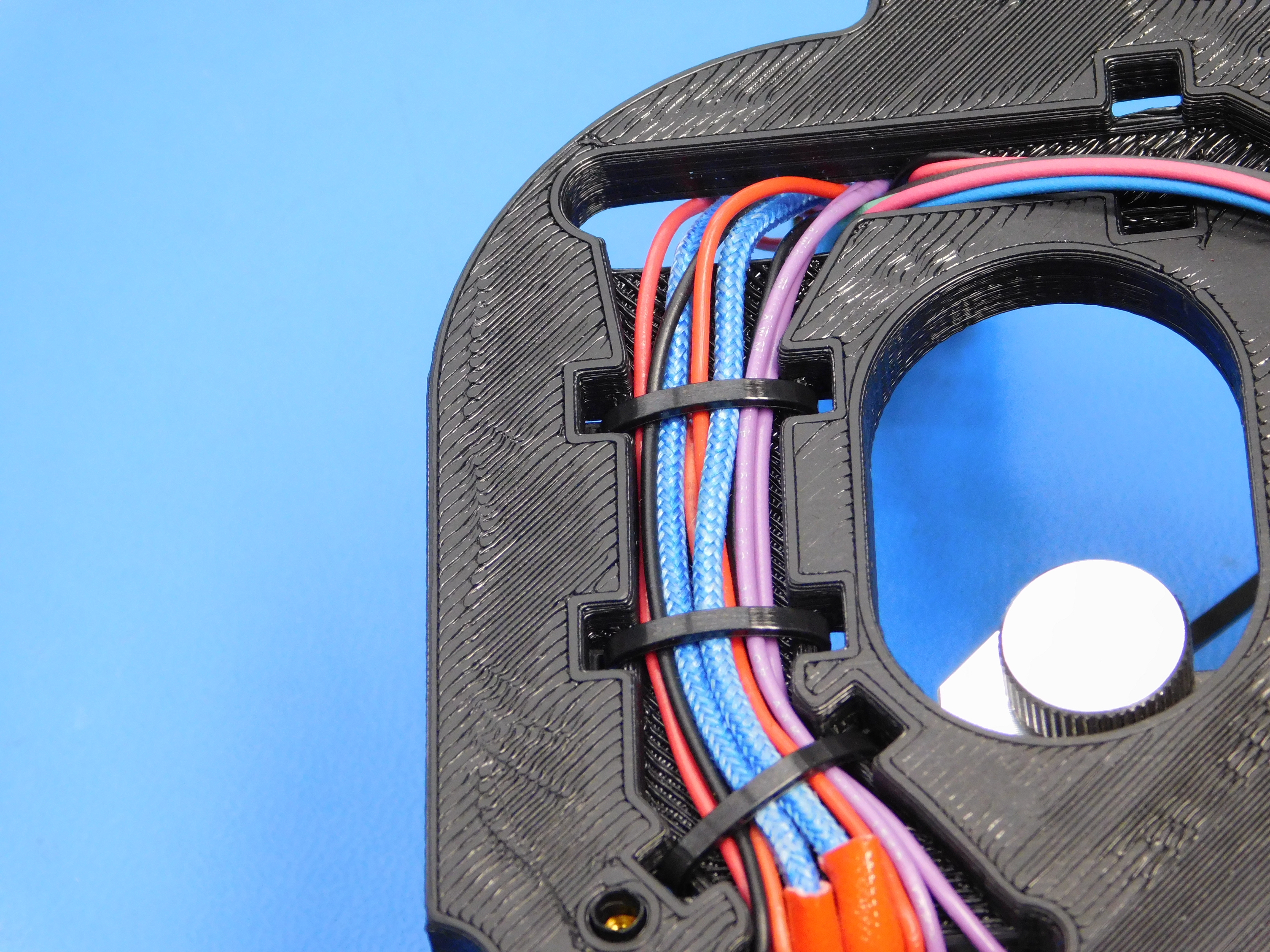
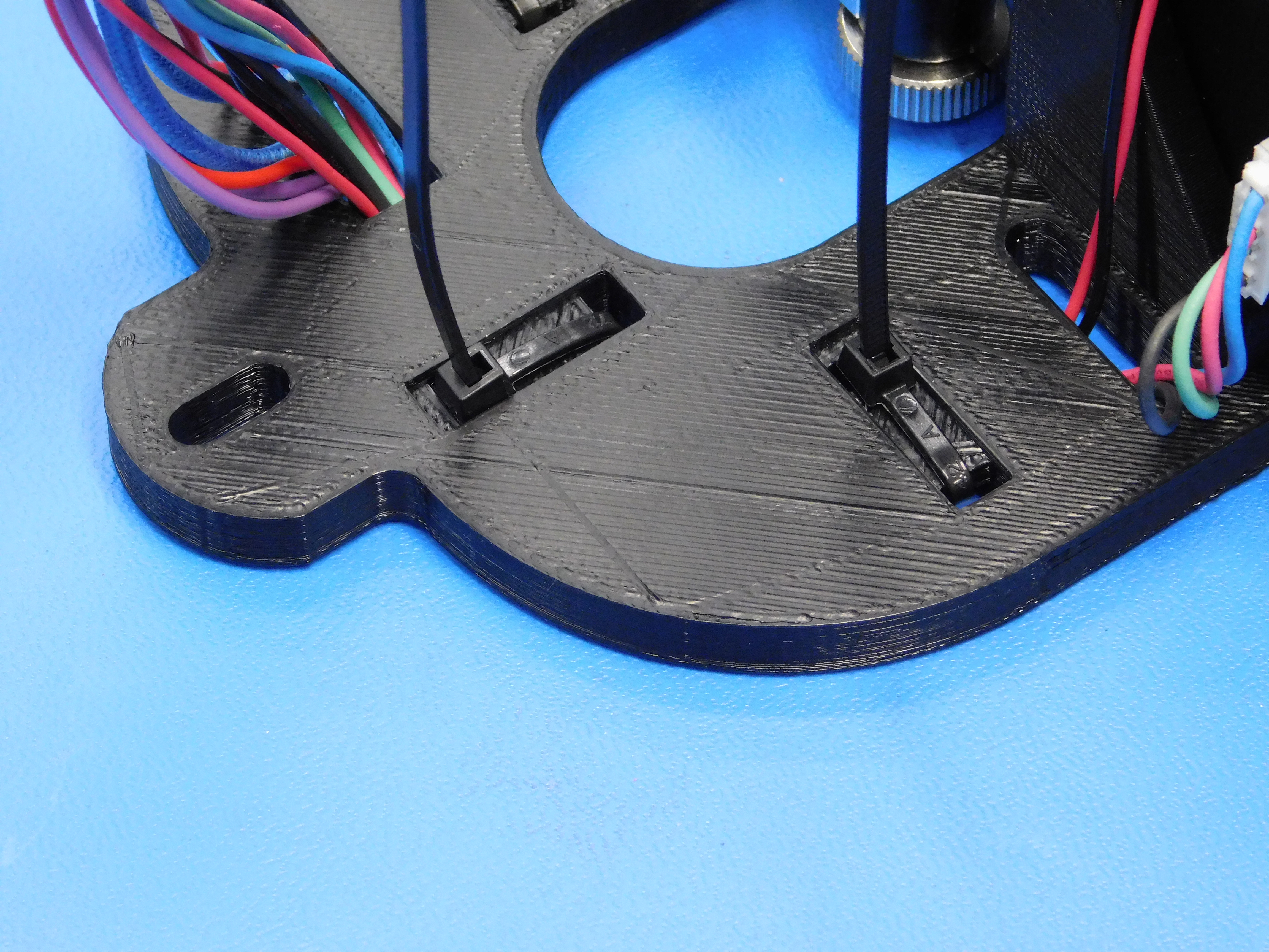
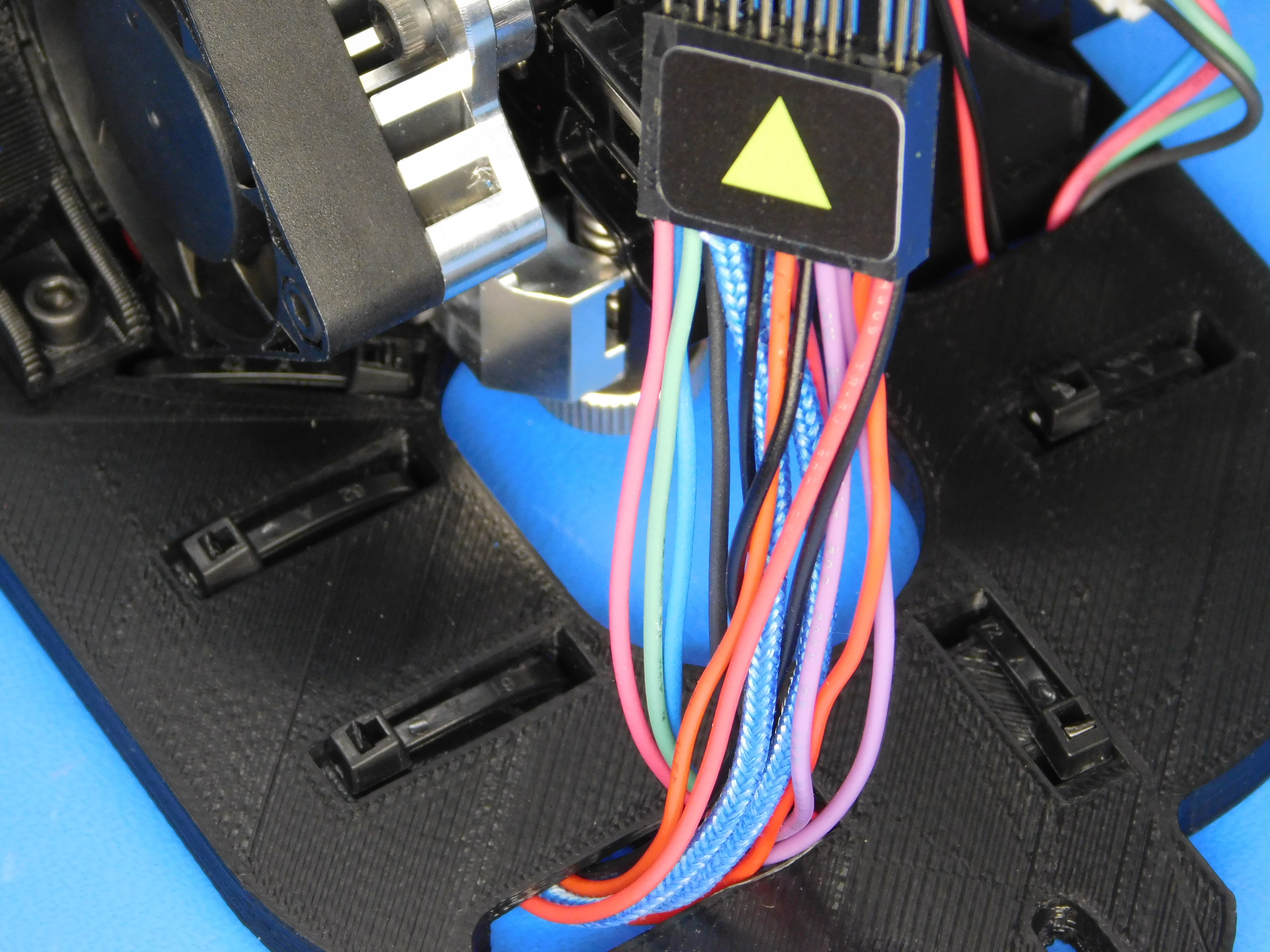
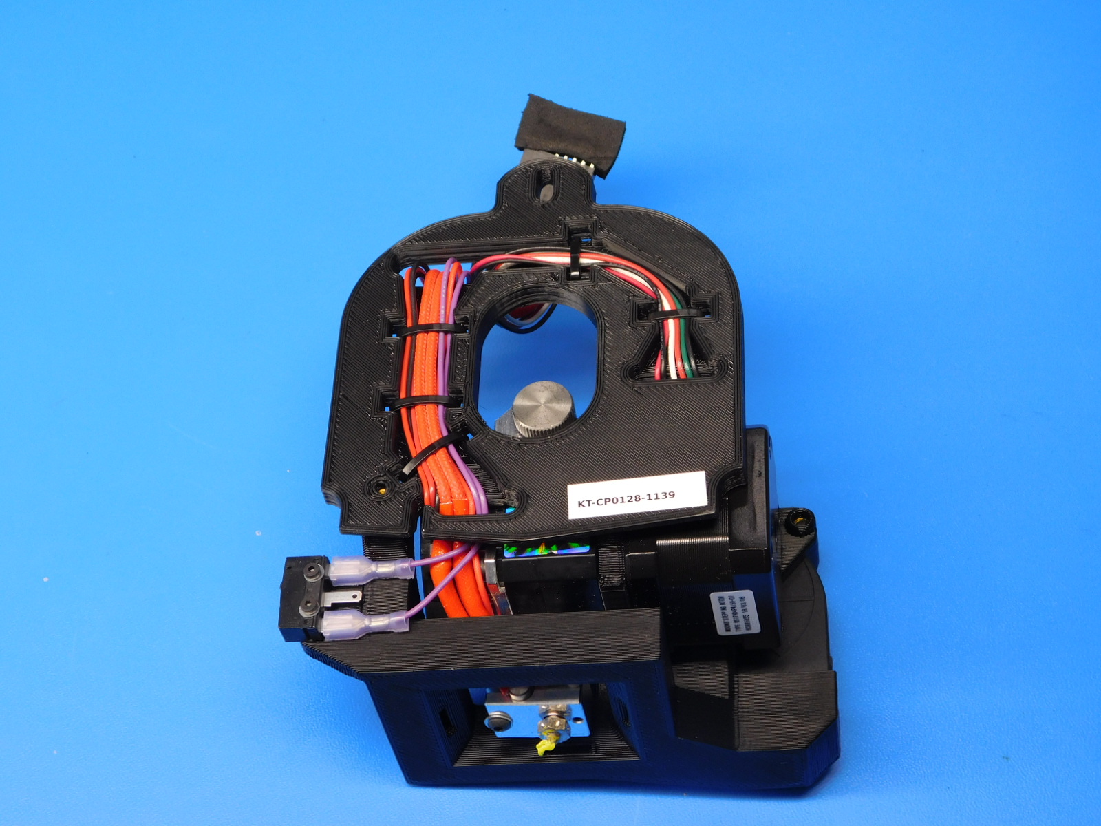
Install the remaining Zip-Ties to secure the harnesses as pictured.
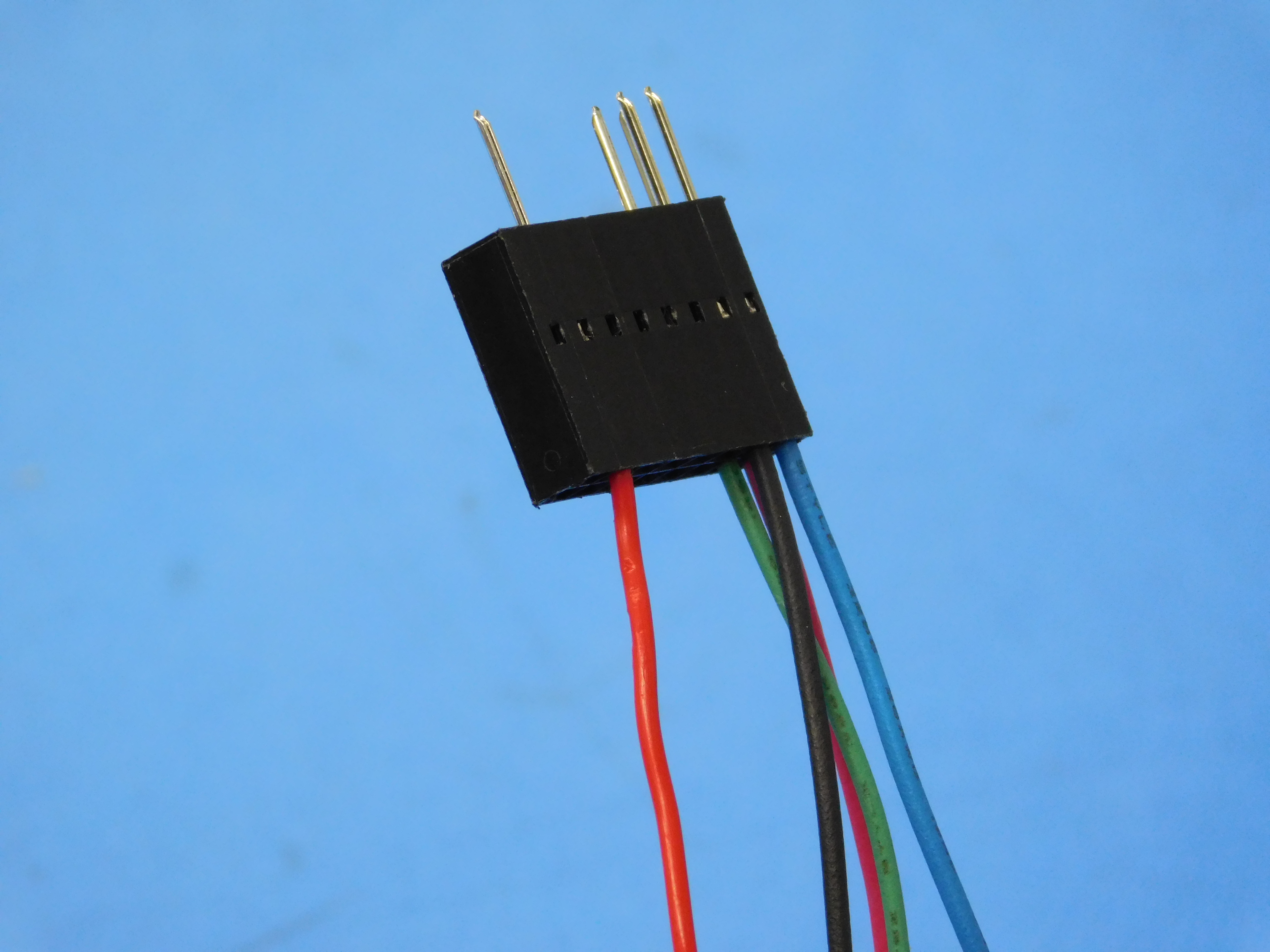
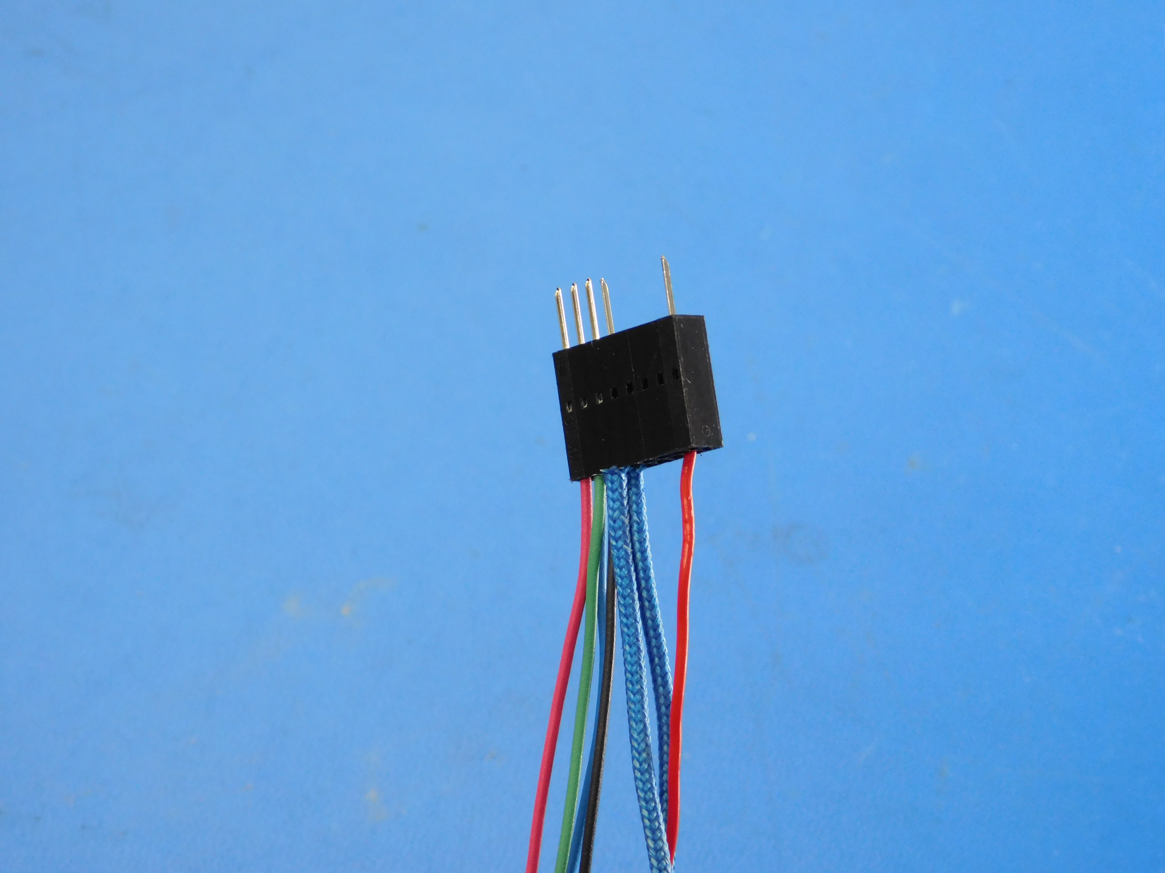
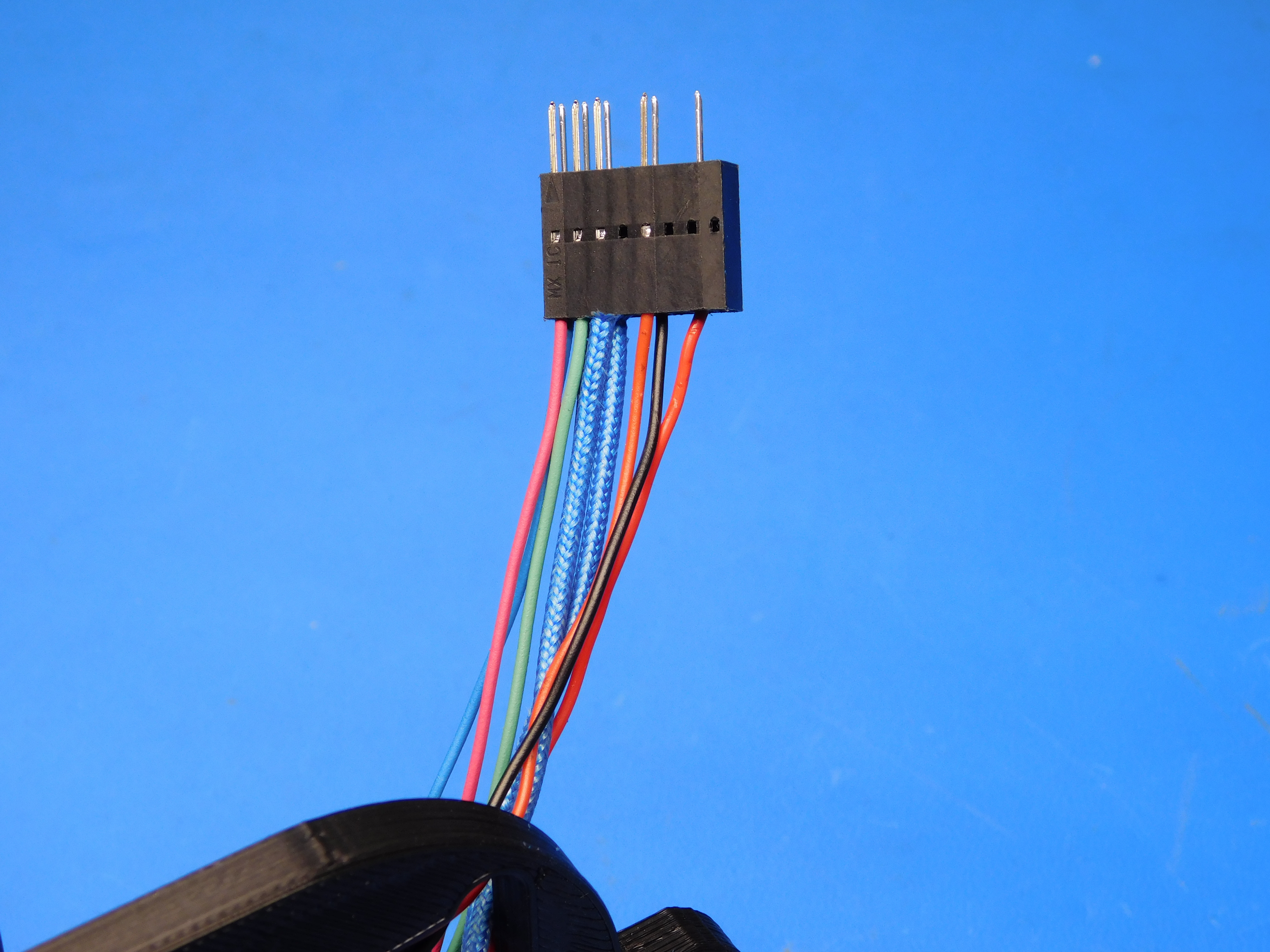
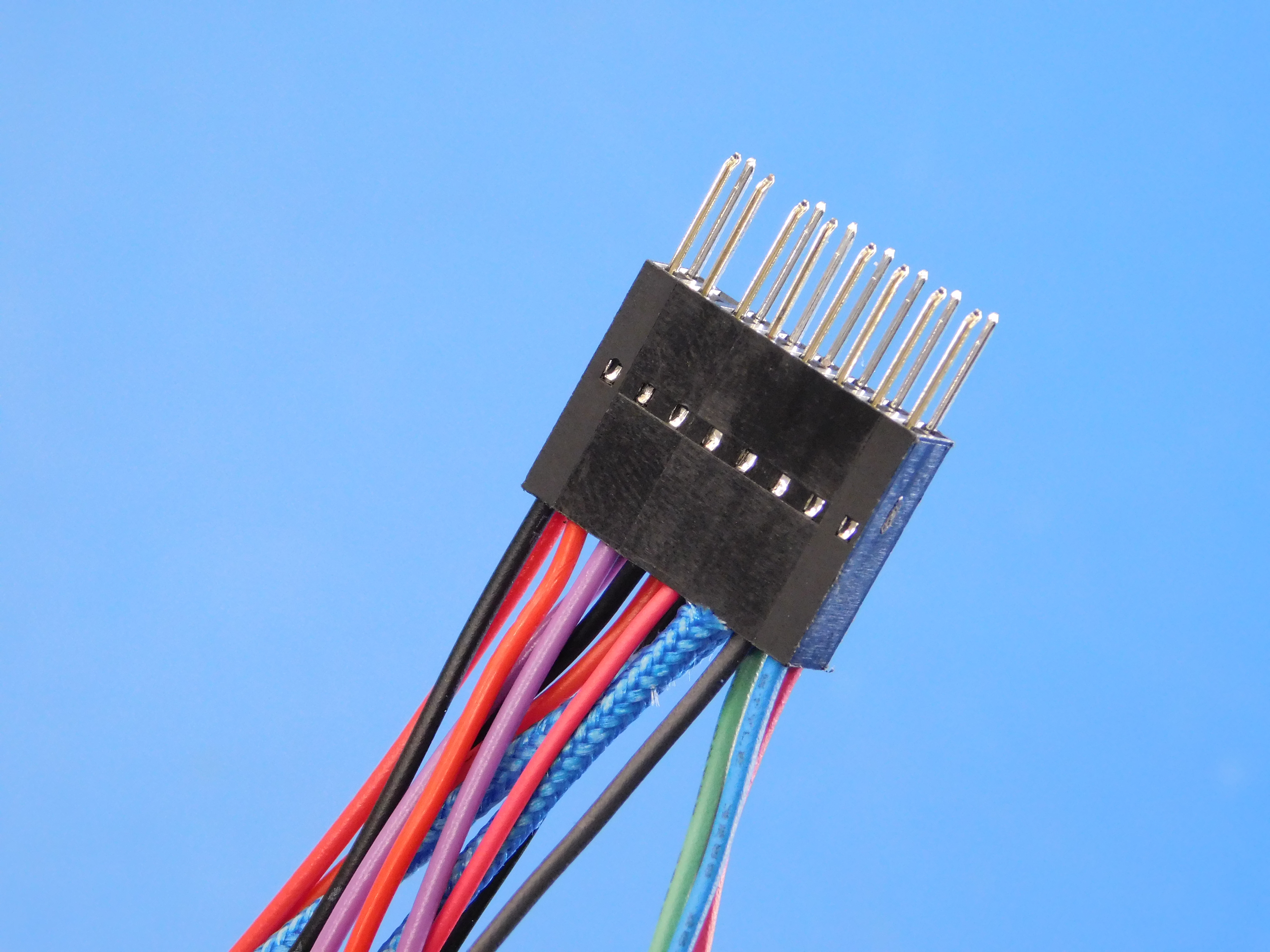
Ensure all terminals are securely in the connector according to the diagram. This diagram can also be found here: https://devel.lulzbot.com/TAZ/accessories/angelfish/Electronics/AS-TH0052_Extruder_Pin_Assignments.odg
A larger version of the image is here: https://ohai.lulzbot.com/media/uploads/AS-TH0052_Extruder_Pin_Assignments.jpg
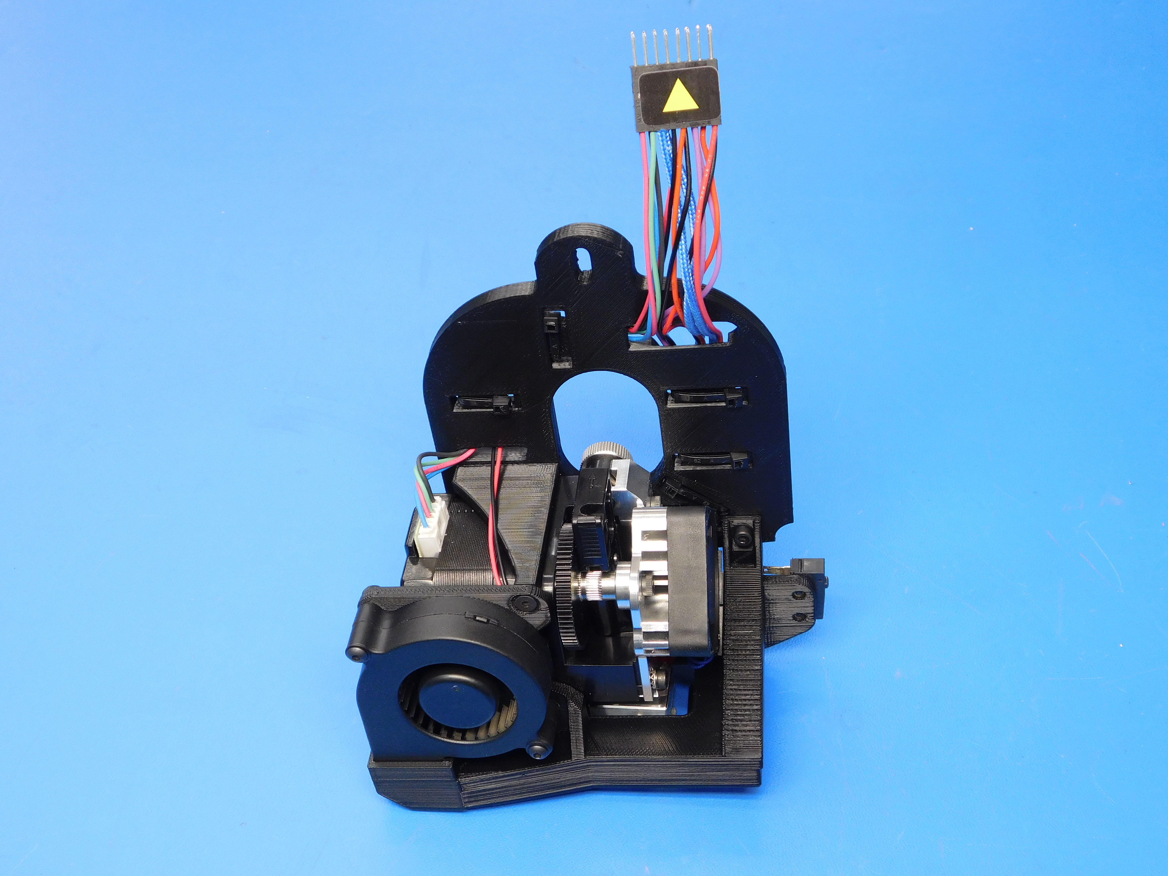
Affix one DC-LB0104 to the Pin 1 side of the connector as pictured.
You've successfully built a TAZ AeroStruder!

After assembly of the TAZ AeroStruder is complete, it is necessary to verify the electrical properties of the toolhead, namely the heater cartridge and thermistor.
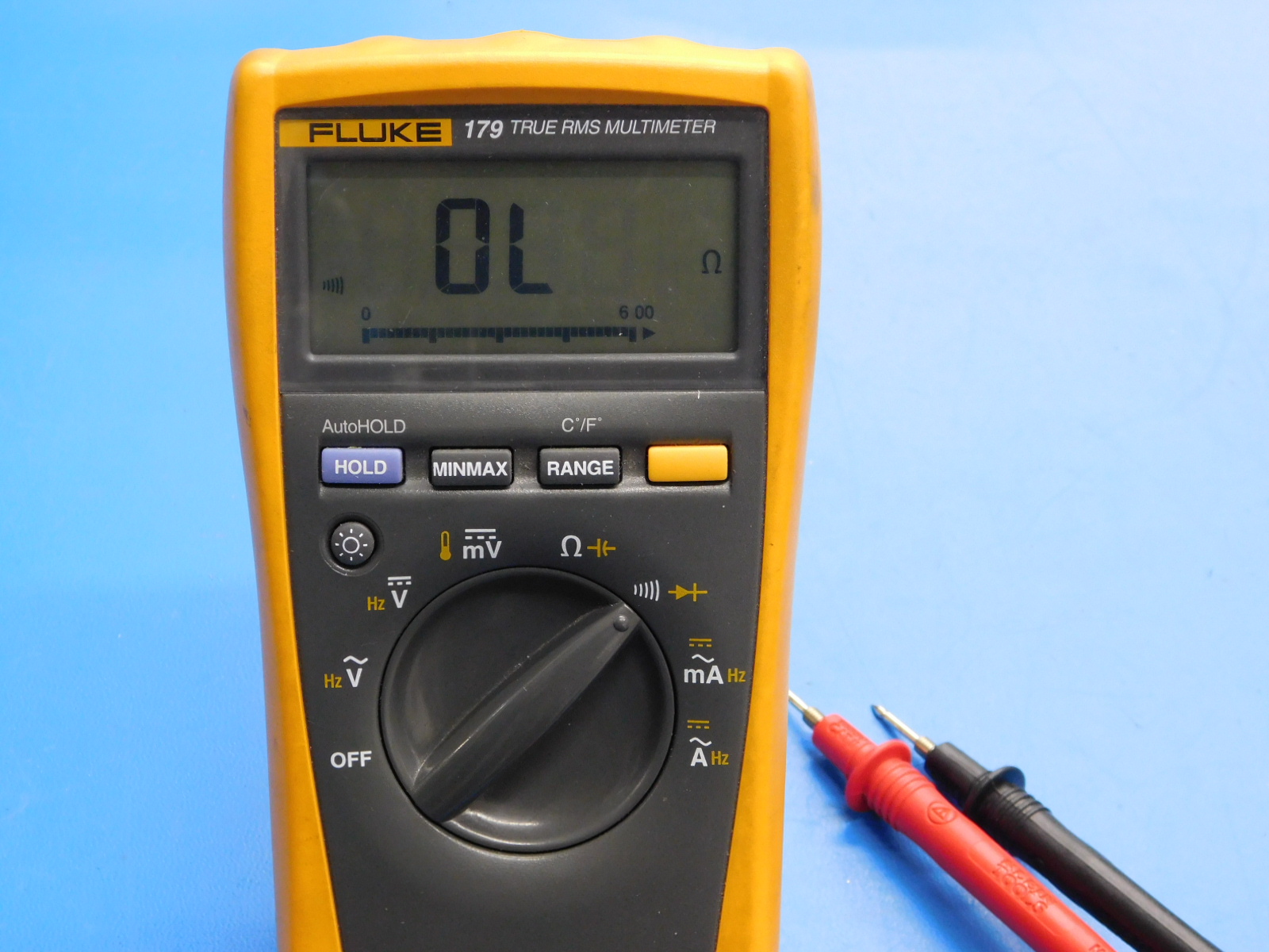
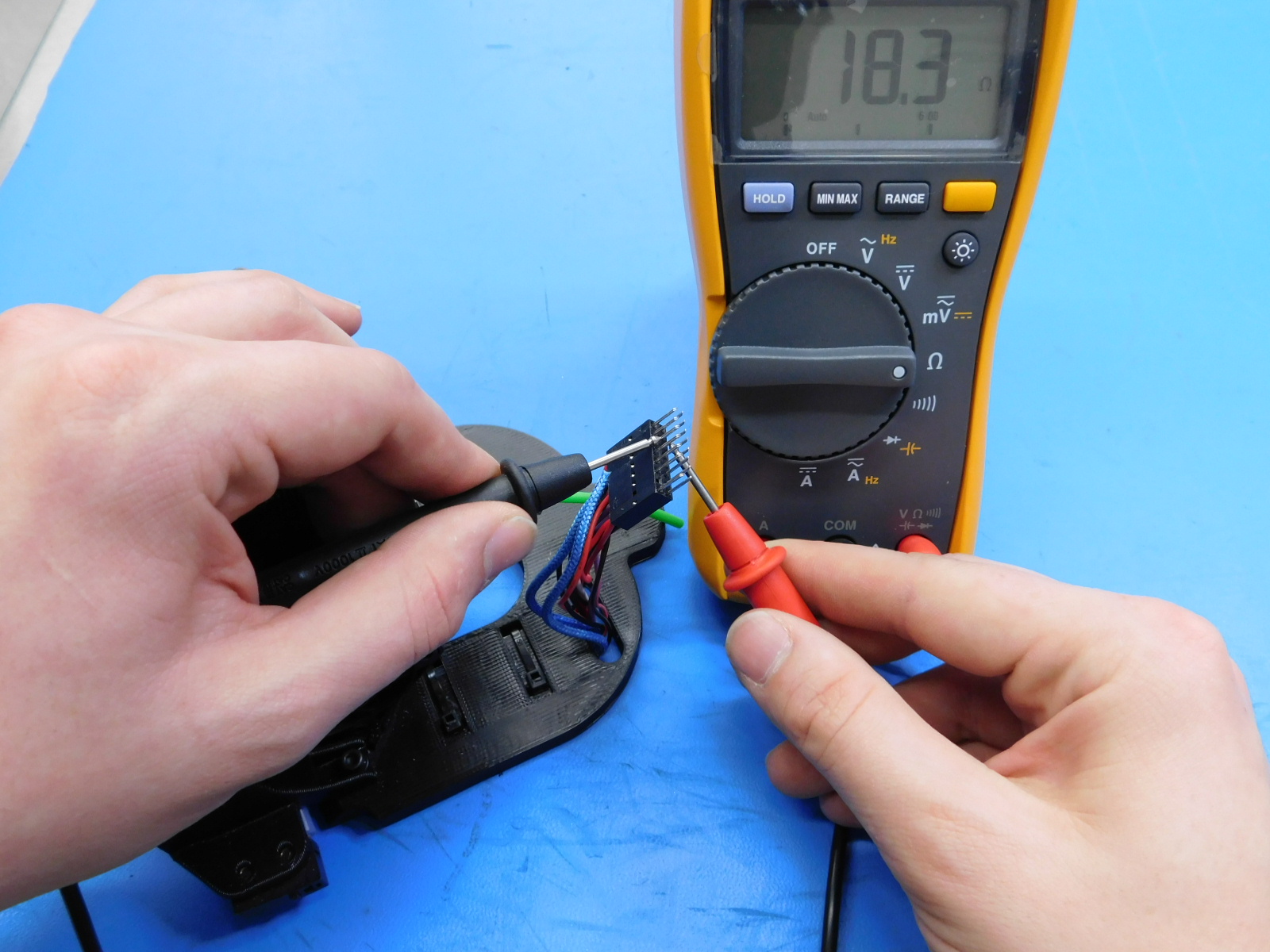
First we will test the resistance value of the heater cartridge;
To do so, first set your multimeter to Ohms which is signified by the capital Greek letter Omega.
Now touch the probes of your multimeter to pins 5 & 6 individually.
Note: Positive or negative probe positions are irrelevant to this test.
The display on the multimeter should now show a value around 19 Ohms.
Any value between 17.5 and 21.3 Ohms is acceptable, values outside of that range are cause for rejection of the heater cartridge and it should be replaced.
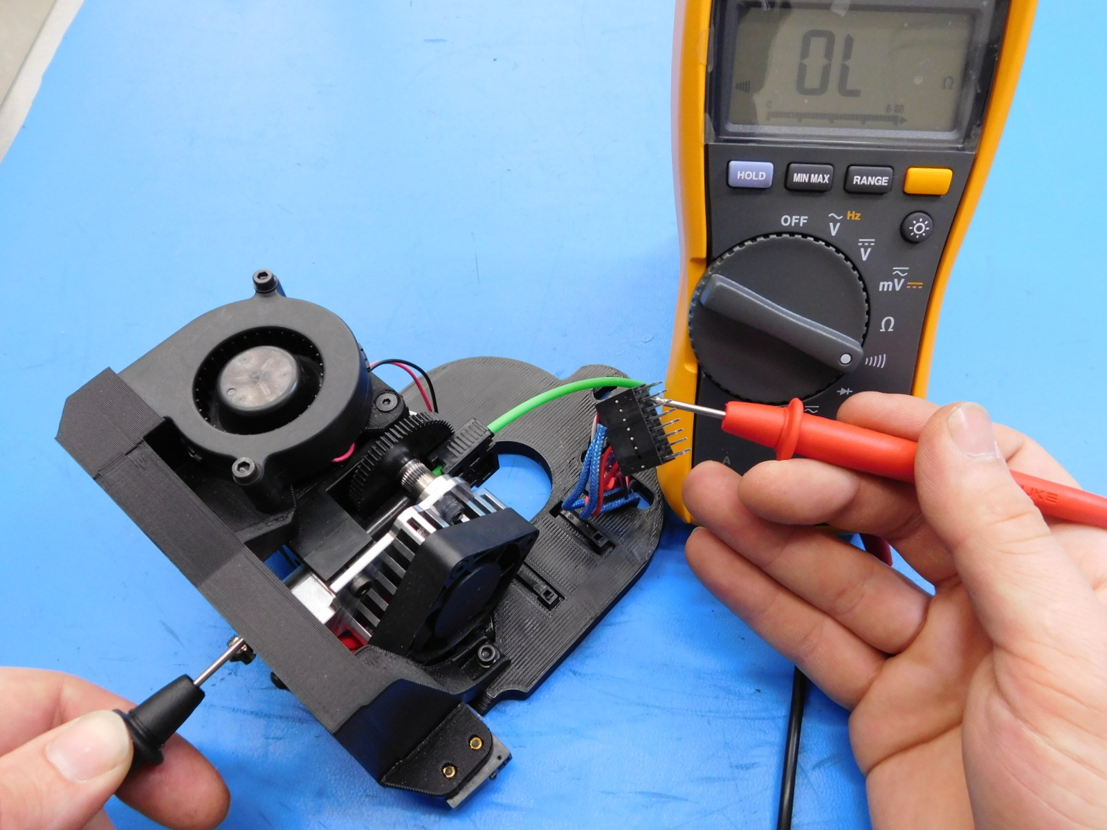
Next we will verify that the heater cartridge DOES NOT have continuity to the ground circuit.
To do so, the multimeter may remain in Ohms mode or be switched to an audible continuity test mode by moving the switch to the symbol representing sound waves.
Now touch one probe to the heater block, and the other to pins 5 & 6 individually.
Note: Positive or negative probe positions are irrelevant to this test.
Whether probing pin 5 or 6, the multimeter display should remain at 0 and no audible alarm should sound.
This indicates that there is no continuity between either lead of the heater cartridge and the toolheads ground circuit.
If the multimeter display reads anything but 0, or an audible alarm is heard during either half of this test, the heater cartridge must be rejected and replaced.
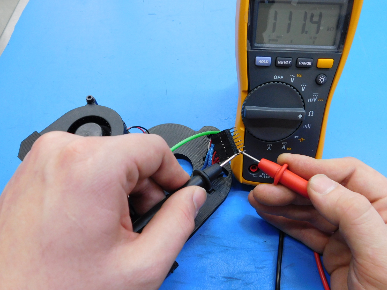
Next we will perform the same tests for the thermistor.
To do so, first set your multimeter to Ohms which is signified by the capital Greek letter Omega.
Now touch the probes of your multimeter to pins 15 & 16 individually.
Note: Positive or negative probe positions are irrelevant to this test.
The display on the multimeter should now show a value between 80 and 120 K Ohms.
Pay close attention to the units displayed on the multimeter's display; the letter 'K' should be displayed to the right of the value.
If a reading is given in Ohms or Mega Ohms (indicated by the letter 'M' to the right of the value displayed) or the kOhms reading is too low (values displayed as 1.xx or similar) or otherwise outside of the range stated above, the thermistor must be rejected and replaced.
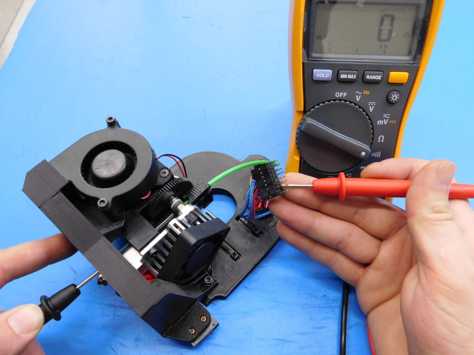
Next we will verify that the thermistor DOES NOT have continuity to the ground circuit.
To do so, the multimeter may remain in Ohms mode or be switched to an audible continuity test mode by moving the switch to the symbol representing sound waves.
Now touch one probe to the heater block, and the other to pins 15 & 16 individually.
Note: Positive or negative probe positions are irrelevant to this test.
Whether probing pin 15 or 16, the multimeter display should remain at 0 and no audible alarm should sound.
This indicates that there is no continuity between either lead of the thermistor and the toolhead's ground circuit.
If the multimeter display reads anything but 0, or an audible alarm is heard during either half of this test, the thermistor must be rejected and replaced.
To finalize this test, verify that the zero sense line (ground circuit) has continuity to the nozzle.
This test is best performed in the audible continuity mode.
Touch one probe to the nozzle or heater block, and the other to pin 14 on the toolhead's connector.
Note: Positive or negative probe positions are irrelevant to this test.
An audible alarm should sound indicating that continuity is present.
If so, the toolhead has passed electrical testing and may proceed to final extrusion testing.
Congratulations!


Put the toolhead onto the test stand and run the test gcode. Make sure:
1) The heatsink fan is on anytime the tool's controller is powered on
2) That the blower fan runs without being too noisy or jittery
3) That the Hotend heats up in a controlled way
4) The stepper motor moves without skipping
Visually verify the extrusion and make sure there is no debris.
Remove the remaining filament from the tool head. Once the tool head is cool, insert a cold piece of filament into the tool head and trim it to approximately 30mm of filament.